E-COMPACT TWIST kW HE Condensing Pellet Boiler
|
|
|
- Aron Gordon
- 5 years ago
- Views:
Transcription


1 E-COMPACT TWIST kW HE Condensing Pellet Boiler UIN-UK INSTALLATION, OPERATION AND MAINTENANCE MANUAL Please read these instructions carefully before installing and/or lighting the appliance for the first time. Keep this document near the appliance, in a place which can easily be reached.
2 TABLE OF CONTENTS 0. INTRODUCTION 1. GENERAL AND SAFETY INFORMATION 1.1 Symbols used in this manual 1.2 Safety instructions 2. TECHNICAL FEATURES OF THE E-COMPACT TWIST BOILERS 2.1 General description of the BCH Boilers 2.2 Description of boiler operation 2.3 Technical data 3. FUEL 3.1 Fuel considerations 3.2 Fuel consumption 4. BOILER INSTALLATION 4.1 General warnings 4.2 Unpacking 4.3 Location of the boiler 4.4 Combustion fumes discharge. 4.5 Fuel storage and feeding. 5. HYDRAULIC INSTALLATION 5.1 Hydraulic connections 5.2 Double temperature set point. 5.3 Hydraulic schemes 6. ELECTRICAL CONNECTIONS 6.1 Warnings 6.2 Boiler control board diagram 6.3 Wiring 6.4 Room thermostat 6.5 Boilers in cascade 6.6 Lambda probe kit 6.7 Ethernet device kit 7.4 Customization menu (Installer) 8. COMMISIONING 8.1. Water filling 8.2. Boiler parameters setting 8.3. First pellet load 8.4. Turning the boiler ON/OFF. Unlock Manual selection power 8.6. Boiler and Buffer temperature set point Winter-Summer Reset Service 9. BOILER OPERATION 9.1 Circulation pump control 9.2 Fans control 9.3 Augers 9.4 Fire/smoke dumper actuator 9.5 IGNITION mode 9.6 RUN and STANDBY mode 9.7 EXTINCTION and BLOCK mode 9.8 DHW Production 9.9 Automatic cleanings 10. CLEANING AND MAINTENANCE 10.1 Combustion chamber and heat exchanger tubes Burner. 11. ASH REMOVAL 12. LIST OF ERRORS. CAUSES AND ACTIONS TO BE TOKEN. 13. LIST OF CONTROL PARAMETERS 7. CONTROL PANEL 7.1 Display 7.2 Structure and management of the menu 7.3 Settings menu (User) 2

3 0. INTRODUCTION Dear customer, The product you have chosen is a biomass boiler with condensation technology, that is, one of the most efficient boilers - with least emissions - in the market. The pellet dew point is around 45 C, and the boiler s efficiency is above 100% then this event takes place. The return temperature of a heating circuit depends on the chosen system: This boiler can work at seasonal performances surpassing 103% efficiency, while high class biomass boilers work up to 95%, and mid class appliances barely reach 91% efficiency. Heating systems Radiators Low temperature radiators Floor heating Usual return temperatures 60 C 40 C - 50 C 30 C - 35 C Condensation technology During the combustion process, steam is released from the moisture contained in pellet. Condensing boilers exploit the latent heat of vaporization (change of state heat) condensing the steam from the flue gas and transferring this heat to the water circuit of the boiler. That is, they take advantage of a heat that would otherwise be lost along with the flue gases through the chimney. As a result, flue gas temperature is below 50 C under condensation conditions, and below 70 C under non-condensing. In the case of conventional boilers, flue gas temperature is usually between 120 C and 200 C. Condensation happens when flue gas reach a temperature below the so-called dew point. This return temperature must be between 30ºC and 40ºC for the flue gas to reach the dew point. To do this, condensing boilers have a stainless steel heat exchanger, with a larger heat exchange surface, for enabling it to transfer as much heat as possible from the boiler's combustion chamber into usable heat. For this reason, even when working in a non-condensing temperature range, the boiler performance will always be higher than a conventional, that is, a non-condensing boiler, because of its larger heat-transfer surface. This boiler complies with current regulations and has been tested in external laboratories accredited for certifying this type of product. Installation of the boiler, checking and maintenance should be carried out by authorised personnel. 3
4 1. GENERAL AND SAFETY INFORMATION 1.1. SYMBOLS USED IN THIS MANUAL WARNING Indications identified with this warning sign are essential for a proper running of the boiler. DANGER Indications identified with this danger sign warn of potential hazards identified for the integrity of people and things. SUGGESTED USE Indications identified with this sign show suggestions at installation and running SAFETY INSTRUCTIONS. Keep this manual near the appliance throughout its useful life. Before any operation, read the indications contained in this document. This manual holds important information regarding use and maintenance of the boiler. In case of any doubt, contact with your installer, dealer or Service Agent authorised by WES. Installation and maintenance must be carried out in accordance with the current local regulations and the instructions contained in this booklet, and should be performed by accredited and qualified personnel, as required by current regulations. Improper installation or faulty maintenance can cause harm to people, animals or property. In such cases, the manufacturer is absolved from any civil or criminal responsibility. This appliance is only intended for being used in heating systems and indirect production of domestic hot water. Any other use may cause harm to people, animals or property. The running of the boiler should be done in accordance with the local and national regulations as well as European standards. The appliance should be installed inside technical rooms. It is not designed to work outdoors. Boiler room must meet the regulations in force. During installation and running of the appliance, keep children at a safe distance from it. After a long period of shutdown, check the absence of blocking prior to the ignition. 4
5 This appliance should not be used as an incinerator. Use only the fuel specified in this booklet. The Commissioning of this appliance must be carried out by an Authorised Service Agent. This is an essential condition for the keeping the warranty of this appliance. In order to improve the product, specifications are subject to change without notice. This boiler is an electrical appliance. Before carrying out any work inside the boiler, make sure that it is isolated from the mains electricity supply. The combustion chamber must always remain closed when the appliance is running. Under no circumstances should be the door opened when there is a flame inside. Risk of burns and fire. WES refuses to accept any responsibility in the event that the appliance or any accessory has been improperly used or modified without authorisation. For all replacement of parts, only original WES spare parts must be used. 2. TECHNICAL FEATURES OF THE E-COMPACT TWIST BOILERS 2.1. GENERAL DESCRIPTION OF THE BCH BOILERS E-COMPACT TWIST 25/30/35/45/50/70/100 are condensing biomass boilers which use as fuel ENplus-A1 pellets only. This appliance consists of a boiler body and an underfed pellet burner. The burner can be fitted to the right of the boiler or left, upon request. The boiler body is constructed of sheet steel, stainless steel and corrosion resistant materials throughout the flue gas circuit as well as all parts that may be in contact with condensate. Combustion chamber is cylindrical and the flue pipes are arranged concentrically around this chamber. At the rear of the boiler there are placed hydraulic connections (flow, return, drain and water cleaning jets), as well as flue gas pipe and condensate drain. The condensate discharges through a drain at the bottom of the boiler, where a water trap is installed (see section 5.- Hydraulic Installation) The boiler includes an automatic cleaning system of the burner plate, which wipes ashes onto a manually removable ash drawer. It also includes an automatic water jet system for cleaning the heat exchanger flue gas pipes. Pellet is fed from an external hopper/silo through an auger. The boiler is commanded by a pre-programmed electronic board that allows a fully automated performance. The following safety and control devices are also supplied: - Combustion chamber temperature probe. When it reaches 890 C the boiler enters in blocking mode. - Mechanical safety thermostat. When it reaches 105 C the boiler disconnects auger feeding. - Water temperature probe. When it reaches 100 C, the boiler enters in blocking mode. - Water pressure probe. When preset low/high pressure is reached, the boiler enters in blocking mode. - Combustion chamber differential pressure sensor. When preset low/high depression is reached, the boiler enters in blocking mode. - Fire/smoke damper actuator. Spring-return actuator which tightly closes pellet feeding. 5
6 - Snap disc thermostat in pellet feed pipe. Close the damper actuator if the temperature of the feed tube pellet reaches 80 C. - Temperature sensor in the smoke box. Blocks if it reaches 100 C. - For safety, provided that the boiler temperature is greater than 72 C, the output of the boiler which controls the circulating pump is activated DESCRIPTION OF BOILER OPERATION. During normal operation, most of the surfaces of the appliance are hot. Take the appropriate precautions. Fuel (pellet) enters onto the burn plate from below through an auger driven by a gear motor. Pellet is fired by a hot air ignition resistance. The whole operation is fully automated. The flame is born in the burn plate, controlled by a combustion air fan (blower). This fan provides first combustion air (primary air) as well as afterburning air (secondary air), which is injected through a liner placed in the combustion chamber. Thus, a thorough combustion is achieved. Combustion gases ascend in the combustion chamber and descend through the coil-wound heat exchanger. Flue gases are finally evacuated at the lower rear of the boiler. For easing the evacuation of combustion gases, as well as ensuring a minimal depression in the combustion chamber, an exhaust fan is installed at the flue gas outlet box. Condensate is drained by gravity, at the bottom of the boiler. Ash removal, from the burn plate to the ash drawer, is performed automatically. The ash drawer must be emptied manually with a cadence that depends on the boiler working hours. The coil-wound heat exchanger is cleaned by water jets, controlled by a water solenoid valve placed at the rear of the boiler. This cleaning is performed automatically whenever the boiler enters in EXTINCTION or STANDBY mode and the combustion chamber temperature is low enough. The E-COMPACT boilers operate with a low temperature set point (heating) and a high temperature set point (DHW). When there is demand for DHW, the boiler temperature rises to meet the demand. Once satisfied, he returns to work in the heating set point. The operation of the boiler and equipment incorporated appears further explained in section 9.- Boiler operation. 6
7 2.3. TECHNICAL DATA Dimensions Type BCH-25 BCH-30 BCH-40 BCH-50 BCH-60 BCH-70 BCH-100 A mm B mm C mm D1 mm E1 mm F1 mm G1 mm H1 mm Water flow/return connection GAS/M 1-1/4 1-1/4 1-1/2 1-1/2 1-1/2 1-1/2 2 Cleaning connection GAS/M 1/2 1/2 1/2 1/2 1/2 1/2 1/2 Water drain GAS/M 1/2 1/2 1/2 1/2 1/2 1/2 3/4 connection Flue gas pipe diameter mm Ash drawer capacity lit Dry weight kg
8 Technical data Type BCH-25 BCH-30 BCH-40 BCH-50 BCH-60 BCH-70 BCH-100 Nominal heat output kw 24,9 30,0 40,0 50,0 60,0 65,7 100 Condensing heat output kw 25,8 31,2 41,8 52,4 63,5 69,9 106 Range of power output Efficiency PNOM / PMIN (70 C/50 C) Efficiency PNOM / PMIN (50 C/30 C) Min. required draft PNOM / PMIN kw 7,5/10/15/ 20/24,9 9/12/18/ 24/30 12/16/24/ 32/40 15/20/30/ 40/50 18/24/36/ 48/60 19/26/39/ 52/66 30/40/54/ 68/100 % 94,5 / 93,1 94,5 / 93,0 94,6 / 91,9 95,3 / 93,1 95,3 / 94,1 95,0 / 93,8 99,1 / 98,0 % 101,5 / 100,5 101,5 / 100,5 100,6 / 98,5 102,0 / 97,7 102,0 / 97,7 101,7 / 97,7 105,3 / 101,8 Pa 8 / 5 8 / 5 8 / 5 8 / 5 8 / 5 8 / 5 8 / 5 Flue gas temp. PNOM / PMIN (70 C/50 C) C 70 / / / / / / / 47 Flue gas temp. PNOM / PMIN (50 C/30 C) C 50 / / / / / / / 37 Exhaust gas mass flow PNOM/PMIN (70 C/50 C) g/s 13 / 6 18 / 6 24 / 7 27 / / / / 18 CO (10%O2) mg/m OGC (10%O2) mg/m < 1 < 1 < 1 3 Dust (10%O2) mg/m NOX (10%O2) mg/m Water capacity l Water side resistance 10K mbar Water side resistance 20K mbar Water operating temperature range C Min. water temperature boiler C Max. operating pressure bar Test pressure bar Electrical consumption (PNOM / PMIN / Standby) W 104 / 56 / / 56 / / 73 / / 73 / / 75 / / 75 / / 230 / 15 Class (EN 303-5:2012)

9 3. FUEL 3.1. FUEL CONSIDERATIONS This appliance has been designed for running exclusively on 6 mm diameter wood pellet, quality ENplus class A1 according to EN standards. Solid biofuels - Fuel specifications and classes - Part 2: Wood pellets for non-industrial use. ENplus-A1 pellet can be made of stem wood and/or chemically untreated residues from the wood processing industry. Its main properties are the following: Property Threshold values ENplus-A1 Diameter mm 6 or 8 Length mm 3,15 L 40 Moisture content % 10 Ash content % 0,7 Net Calorific Value MJ/kg 16,5 Q 19 kwh /kg 4,58 Q 5,28 The fuel supplier must provide certified documentary evidence of its pellet quality FUEL CONSUMPTION The burner is modulating, with five modulation steps for each output. The boiler chooses automatically the optimal step for each need. The following charts show outputs and subsequent fuel consumption for each boiler model at each modulation step: Modulation step BCH-25 Heat output kw 7, Pellet consumption (70 C/50 C) kg/h 1,7 2,3 3,4 4,5 5,6 Pellet consumption (50 C/30 C ) kg/h 1,6 2,1 3,2 4,2 5,3 BCH-30 Heat output kw Pellet consumption (70 C/50 C) kg/h 2,1 2,7 4,1 5,4 6,7 Pellet consumption (50 C/30 C ) kg/h 1,9 2,5 3,8 5,0 6,3 BCH-40 Heat output kw Pellet consumption (70 C/50 C) kg/h 2,7 3,6 5,4 7,1 8,8 Pellet consumption (50 C/30 C ) kg/h 2,5 3,4 5,0 6,7 8,3 BCH-50 Heat output kw Pellet consumption (70 C/50 C) kg/h 3,4 4,5 6,6 8,8 10,9 Pellet consumption (50 C/30 C ) kg/h 3,2 4,2 6,3 8,3 10,2 BCH-60 Heat output kw Pellet consumption (70 C/50 C) kg/h 4,0 5,3 7,9 10,5 13,1 Pellet consumption (50 C/30 C ) kg/h 3,8 5,1 7,5 9,9 12,3 BCH-70 Heat output kw Pellet consumption (70 C/50 C) kg/h 4,4 5,8 8,7 11,6 14,4 Pellet consumption (50 C/30 C ) kg/h 4,2 5,6 8,3 10,9 13,5 BCH-100 Heat output kw Pellet consumption (70 C/50 C) kg/h 6,2 8,2 11,1 14,0 20,6 Pellet consumption (50 C/30 C ) kg/h 5,7 7,6 10,3 12,9 19,0 Note: regarding fuel with Net CV = 4.8 kwh / kg 9
10 4. BOILER INSTALLATION 4.1. GENERAL WARNINGS This appliance is only intended for being used in heating systems and indirect production of domestic hot water. Any other use may cause harm to people, animals or property. The appliance should be installed inside technical rooms. It is not designed to work outdoors. Installation and maintenance must be carried out in accordance with the current local regulations and the instructions contained in this booklet, and should be performed by accredited and qualified personnel, as required by current regulations. During installation and running of the appliance, keep children at a safe distance from it. Boiler room must meet the regulations in force UNPACKING Take into account the actual size of the boiler to plan walkways and its connection in the boiler room. Observe local regulations on waste and recycling. Transportation of the boiler should always be done using hand trucks/pallet jacks. Pay attention to possible imbalances due to uncentered loads on the pallet. The BCH boiler will come packaged on a single 800 x 1200 pallet. The smoke box and the extraction fan is supplied disassembled to facilitate passage through doors. The minimum width for the boiler to be carried without disassembling is 750 mm. Type BCH-25 BCH-30 BCH-40 BCH-50 BCH-60 BCH-70 A [mm] B [mm] H [mm] Pallet [mm] C Minimum passage width [mm] x BCH x


11 To facilitate the operation of lowering the boiler from the pallet, some useful designed for this purpose can be supplied on request. Insert the useful in the holes in the base of the boiler. Actuate both lifting mechanisms gradually and alternately until the boiler stop supporting the pallet. Move the lifting mechanisms along the frame to lift the boiler levelled. Hold the boiler manually to avoid imbalances. Risk of falling boiler in case of unbalanced elevation. Remove the pallet. Move the boiler to its final location and pose the boiler on the floor. Remove the mechanisms from the boiler holes. Slide support for a level elevation The mechanisms for lowering the boiler from the pallet must not be used for large displacements. These displacements should be performed by hand trucks/pallet jacks 11
12 4.3. LOCATION OF THE BOILER The boiler room must comply with air venting requirements and regulations applicable in terms of fire protection, safety in use, etc. The boiler should be installed in a boiler room frost-protected. An adequate supply of combustion air and ventilation openings should be ensured by minimum net free area of 10 cm 2 for each kw of nominal heat output, never less than 200 cm 2. The boiler must have an adequate smoke discharge. All necessary safety distances to combustible materials must be respected. Locating the appliance in a room with an explosive/flammable atmosphere is prohibited The boiler must have around it clearance enough to let servicing be carried out easily. Be aware of complying minimum distances imposed by local regulations The minimum distances shown in the diagrams are: L1 mm Separation to the wall L2 mm Necessary to remove the burner L3 mts Required minimum width of the boiler room L4 mm Necessary for flue gas evacuation and drainage installation L5 mm Necessary to remove the ash pan and door opening. L6 mts Required minimum depth of boiler room 4.4. COMBUSTION FUME DISCHARGE. 12

13 This boiler shall not be connected to a venting system that serves a second appliance fired by other fuel. The smoke duct for the discharge of fumes must be installed by carried out complying local regulations by qualified personnel. The installation of horizontal sections must have a minimum slope of 3% for letting condensates to drain down to the smoke box of the boiler, where are discharged to the sewerage. Smoke duct is composed of a flue pipe and a chimney pipe. Never use a flue pipe smaller in diameter than the flue connection of the boiler it is being connected to. Type BCH-25 BCH-30 BCH-40 BCH-50 BCH-60 BCH-70 BCH-100 Flue gas connection diameter mm WES recommends stainless steel insulated chimneys resistant to the aggressive action of temperature and combustion products. The calculation of the chimney should be according to EN The data required for the calculation can be obtained from the technical data in section 2.3. A T element must be installed to overcome any solid or liquid obstruction. The recommended draft is 5-8 Pa. A flue draft regulator may be required if the draft installation is higher FUEL STORAGE AND FEEDING. The boiler is fed from a textile silo to the burner through an auger. WES supplies textile silos of different storage capacities and the correspondent feeding auger kits. Silo Reference Dimension [mm] Approx. capacity [Ton] BCSP x 200 x 250 3,0 BCSP x 250 x 250 4,9 BCSP x 300 x 250 6,9 The storage of solid biofuels must comply with current legislation on safety and fire. The filling of the silo is made through a Storz connector supplied with the silo, by a fuel supplier tanker truck. The silo Storz must be ground connected for avoiding electrostatic discharges. Read carefully the instructions supplied with the silo and follow the instructions described therein before filling it. 13

14 Auger connection to the burner is done through a flexible pipe, which must be coupled to the burner inlet, inside the burner enclosure, securing it with the supplied metal bracket. The diameter of the feed connection is 60 mm. Auger electrical supply must be wired on the correspondent connector at the boiler rear. 5. HYDRAULIC INSTALLATION 5.1. HYDRAULIC CONNECTIONS This is a condensing boiler. Condensate discharge to the sewage is done through a 40mm water trap with a height no lesser than 25 cm. The siphon must be filled manually in the first commissioning of the boiler. Rear of the boiler BCH-25 BCH-30 BCH-40 BCH-50 BCH-60 BCH-70 BCH-100 A Water Flow GAS/M 1-1/4 1-1/4 1-1/2 1-1/2 1-1/2 1-1/2 2 B C Water Return *V2V - Heat exchanger cleaning GAS/M 1-1/4 1-1/4 1-1/2 1-1/2 1-1/2 1-1/2 2 GAS/M 1/2 1/2 1/2 1/2 1/2 1/2 1/2 D Water drain GAS/M 1/2 1/2 1/2 1/2 1/2 1/2 3/4 E * Condensate GAS/M 1-1/2 1-1/2 1-1/2 1-1/2 1-1/2 1-1/2 1-1/2 drain trap * These products are supplied with the boiler The following products must be installed along with the boiler - Circulation pump. Its volume flow must be adjusted according to the boiler s nominal heat output and the temperature rise planned for the installation ΔT [ C] Q [l/h] ΔT [ C] Q [l/h] ΔT [ C] Q [l/h] ΔT [ C] Q [l/h] BCH BCH BCH BCH BCH BCH BCH Safety pressure relief valve, rated at 3 bars and taken to sewage (5 bar to BCH-100). 14
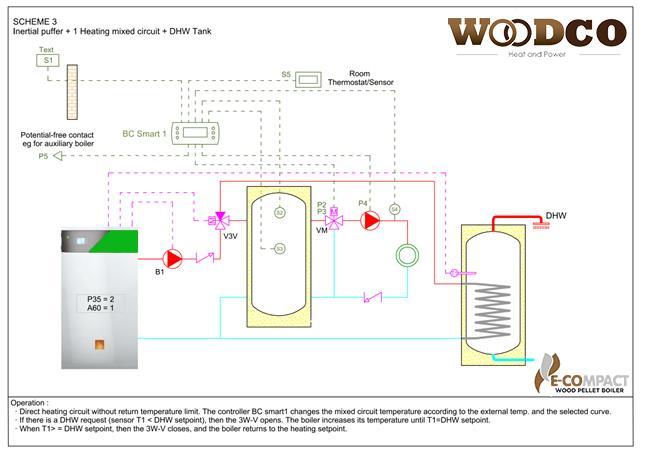
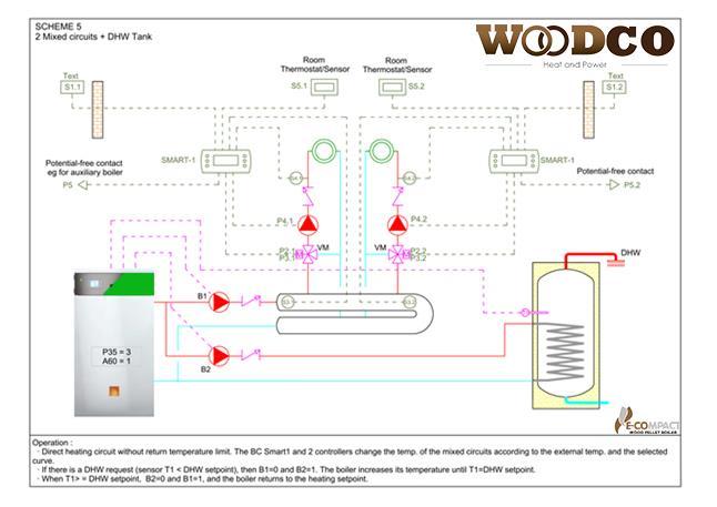
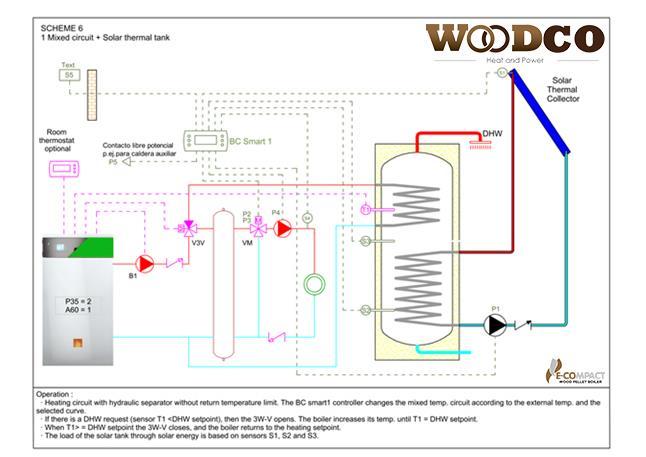
15 - Expansion vessel. The vessel volume will be calculated based on the volume of the entire heating system. - Automatic air vent. - Pressure gauges and thermometers. - Mesh Filters. - Check Valves. - Ball Valves. - Energy Meter. - Condensate water trap. The condensate drain pipe should have a steady incline, with a minimum angle of 3%. If due to the position of the boiler, the condensate cannot be discharged by gravity, a condensate pump should be used DOUBLE TEMPERATURE SETPOINT The boiler can work with two temperature set points. - Low temperature (heating) - High temperature (usually DHW). When there is no demand for high temperature, the boiler operates at low temperature set point. When there is demand for high temperature, the boiler automatically switches its set point value of 70 C (modifiable value Th21-Ih21), so it will increase the temperature of the boiler to this value or until demand (e.g. DHW) is satisfied. The sensor in charge of this control is the buffer probe temperature. This feature is only available with if the parameter P35=2 or 3 (see section 5.3.-Hydraulic schemes). To enable this function, set the parameter A60=1 (SYSTEM MENU ENABLES). This functionality allows the maximum efficiency because the boiler only will work temporarily at high temperature, working most of the time at low temperature. 15
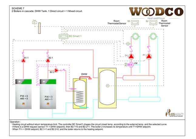
16 For further information on this feature, see section DHW Production HYDRAULIC SCHEMES The boiler is able to control the following outputs: Description Parameter P35 The boiler controls a pump (heating only, without DHW) 0 The boiler controls a pump and a 3-way valve. 2 The boiler controls two pumps. One for the low-temperature circuit and another one for high temperature (usually DHW). 3 The boiler controls a pump (buffer tank) 4 The control of these outputs is made by the following sensors: Boiler temperature probe DHW/Buffer temperature probe Room thermostat (See section Room thermostat) The choice of the hydraulic schemes is made by assigning the value of parameter P35 according to the desired scheme (SYSTEM MENU DEFAULT SETTINGS PARAMETER P35) To control more circuits (incl. Thermal Solar) or variation of the flow temperature by mixing, Woodco Energy Ireland have an external unit (BC Smart 1) able to perform such controls and functions. For further information see the manual of the controller BC SMART-1. 16
17 17
18 18
19 19
20 20
21 21
22 22
23 6. ELECTRICAL CONNECTIONS 6.1. WARNINGS It is mandatory to install an all pole disconnection switch with contact aperture of at least 3 mm. The boiler must be fully grounded. The electrical installation must be performed by qualified personnel. This boiler must be supplied with a 230V 50Hz electrical supply. Before carrying out any work inside the appliance, disconnect it from the mains BOILER CONTROL BOARD DIAGRAM. Access to the electrical wiring is done by removing the front cover of the boiler, and the metal wiring protection cover. 23
24 24
25 INPUTS OUTPUTS Nº FUNCTION TYPE Nº FUNCTION TYPE 1-2 Line 230V - 50 Hz 230 V 3-4 SF1 Burner auger TRIAC (max 3 A*) 7-8 TTS Safety thermostat ON/OFF 9-10 SF2 Ash drawer auger ON/OFF (max 3 A*) 13 IG Ignition element ON/OFF (max 3 A*) TH Combustion chamber temperature Thermocouple K 16 V3V 3-way valve ON/OFF (max 3 A*) DP Combustion chamber VA Fire/smoke damper differential pressure 12 V 19 (Out 1) actuator sensor ON/OFF (max 3 A*) Safety temperature TS NTC 100k LI Cleaning exchanger (flue gas box) 22 (Out 2) solenoid valve TD DHW/Buffer tank probe NTC 10k ON/OFF (max 3 A*) TC Boiler probe LP Burning plate cleaning NTC 10k 25 temperature (Out 3) linear actuator ON/OFF (max 3 A*) PA Water pressure sensor 5 V B1 Circulation pump ON/OFF (max 3 A*) TTO Room thermostat ON/OFF SFE Silo/hopper loading pellet (Out 4) motor ON/OFF (max 3 A*) 65 FAN3 Exhaust Fan TRIAC (max 1,8 A*) SP Pellet sensor 12 V 67 FAN2 Combustion Fan 2 TRIAC (max 1,8 A*) FAN1 Combustion Fan 1 TRIAC (max 1,8 A*) 25
, might be wired on the connectors placed at the rear of the boiler: Description Cables TYPE 1 Line 3 x 1,5 mm 2 230 V A Room")
 is supplied with the boiler.")
26 * All fed outputs are under fuse and the total current must not exceed 6.3 A WIRING. All sensors and electrical devices included in the boiler are supplied installed and wired. Only the following devices (depending on the system configuration), might be wired on the connectors placed at the rear of the boiler: Description Cables TYPE 1 Line 3 x 1,5 mm V A Room thermostat 2 x 1 mm 2 ON / OFF B DHW/Buffer temperature 2 x 1 mm 2 NTC 10 k 2 Silo/hopper auger 3 x 1,5 mm V 3 Pump 3 x 1,5 mm V 4 3-way valve/ Pump 2 3 x 1,5 mm V 5 Cleaning exchanger solenoid valve Supplied with the boiler 230 V 6 Exhaust fan Supplied with the boiler 230 V The buffer probe (NTC 10k) is supplied with the boiler. The length can be extended by a 2x1 mm2 cable. The electrical connections of the burner are situated on the side of the boiler burner on the drawer. Nº Symbol Designation Nº Symbol Designation 1 Ignitor element 6 Burning plate cleaning linear actuator 2 Combustion plate rotation motor 7 Pellet sensor 3 Combustion FAN Burner auger 9 Signal (control) fire/smoke dumper actuator Signal (control) combustion fan (FAN 1) 5 Fire/smoke damper actuator 10 Limit switches linear actuator 26


27 11 Combustion FAN 2 (Only BCH-100) 12 Ash drawer auger The connections in the rear of the boiler and in the burner are plug-in screwless type. The cable fixing is done by pressing the hole with a screwdriver until you feel that the spring is open. Then insert the cable and remove the screwdriver. Check correct cable fixing. Press the spring Insert the cable 6.4. ROOM THERMOSTAT. The boiler is supplied with default control heating set point temperature. However has the ability to connect a room thermostat. The signal from the room thermostat should be free of potential. Risk of breakage of the control board. The operation is set with parameter A07 (System Menu Enables Parameter A07) A07 Assign the behaviour of the room thermostat Room thermostat disabled. The boiler regulates with the set point temperature. Default parameter. The thermostat is used to switch the boiler from RUN mode to STANDBY mode. The thermostat is used to switch off the circulating pump. Note: For security reasons, if the boiler temperature exceeds 72 C, the boiler keeps the pump on. If the thermostat opens the circuit, the boiler enters mode EXTINCTION. If the thermostat closes the circuit and the boiler is in EXTINCTION mode you need to wait until the end of this phase and the boiler will automatically start the IGNITION cycle. The thermostat is used to switch the boiler from RUN mode to MODULATION mode. In MODULATION mode the boiler works constantly to its minimum power (P1) BOILERS IN CASCADE. The range of E-COMPACT boilers is prepared for multi-boiler systems in parallel (in a cascade). Commissioning of each boiler is via release ON/OFF (thermostat terminals at the rear of the boiler). The start-up sequence must be performed by any controller chosen from those available on the market, for an output on / off potential free. A Room Thermostat Wire 2 x 1 mm 2 WITHOUT VOLTAGE ON / OFF 27


 allows control and monitoring control of the boiler from the Internet, either in local or remote network.")
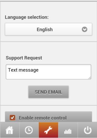
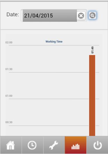
28 6.6. LAMBDA PROBE KIT. As an option, a lambda probe can be installed on any BCH boiler. Its electronic board continuously measures the quantity of oxygen in the flue gas, thus modifying motors and fans setpoint to achieve the finest combustion. The lambda probe kit includes the following products: - Lambda probe with connector - Extension cable with connector - Lambda Module Electronic card - Communication cable to boiler main circuit board - Electrical cable For further information see the manual supplied with the kit Lambda ETHERNET DEVICE KIT. As an option, the monitoring and remote control device EasyCheck can be installed on any boiler. This device (thanks to its web server embedded) allows control and monitoring control of the boiler from the Internet, either in local or remote network. The remote monitoring kit includes the following products: - DIN rail EasyCheck web control unit - Power cables - Communication cable to boiler main circuit board With this equipment you can connect remotely to turn on/off/unlock the boiler, display their status, make time schedules, attendance messaging and recording operating hours and boiler temperatures. 28

29 For further information, see lambda probe kit and remote monitoring kit manuals. 29

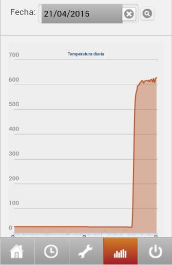
30 7. CONTROL PANEL 7.1. DISPLAY. Boiler temperature Date and time Chrono Combustion power System state Error code Setpoint temperature Lea area Selection keys SELECTION KEYS BROWSING KEYS System ignition if pressed for 3 seconds. Unlock. Alarms Reset if pressed for 3 seconds SETTINGS menu CUSTOMIZATION menu INFORMATION menu Back to Main frame Back to the upper level Up/down scroll Increase/decrease value Left/right scroll Exit from menu saving data Exit from menu without saving data LED Ignition resistance ON Auger ON Pump ON DESCRIPTION (To view, click on the display. In dark, those that are active) 3-way valve/pump 2 ON Fire/smoke damper actuator ON V2V Exchanger cleaning solenoid valve ON Burning plate cleaning linear actuator ON Silo/hopper loading pellet motor ON Lack of pellet Room thermostat contact opened DHW request Winter Mode Summer Mode Press for accessing to the information menu. Information Exhaust T. [ C]: 550 Boiler T. [ C]: 50 Buffer T. [ C]: 50 Safety T. [ C]: 42 WWa Water Press. [mbar]: 2500 Information Exhaust Press. [Pa]: 15 Oxygen [%]: 8 FreqAC [Hz]: 50 30
31 Values shown in the Main frame: CHECK UP System checking IGNITION Ignition (includes different phases). See section 9.5 Ignition mode STABILIZATION Flame stabilization RUN Run mode MODULATION Previous phase to Standby STANDBY Standby mode EXTINGUISHING Extinguishing mode OFF Boiler off BLOCK Boiler locked 7.2 STRUCTURE AND MANAGEMENT OF THE MENU There are two main submenus, SETTINGS menu and CUSTOMIZATION menu. They are accessed by pressing the icons and respectively. Settings Thermostats Summer-Winter Chrono Load Reset Service Customization Keyboard Setting Display System Menu 7.3. SETTINGS MENU (USER) USER MENU DESCRIPTION 1 THERMOSTATS Boiler thermostat For setting Boiler Thermostat set point Buffer thermostat For setting DHW/Buffer Thermostat set point 2 SUMMER-WINTER For choosing season Program: 3 CHRONO - Daily - Weekly Allows scheduling three ON/OFF time lapses for each program. - Weekend 4 LOAD Burner auger load 5 RESET SERVICE Reset counters for the next ash removal THERMOSTATS This menu allows setting boiler thermostat and DHW/buffer thermostat set points. Settings Thermostats Summer-Winter Chrono Load Reset Service Settings Boiler Th. 60 Buffer Th. 55 Settings Boiler Th Settings Buffer Th SUMMER-WINTER This menu allows choosing Summer / Winter operating mode. In Winter mode, there is priority for Domestic Hot Water (DHW). When the DHW set point is reached, the boiler returns to its previous state (RUN or STANDBY). In Summer mode, when the DHW set point is reached, the boiler will be in STANDBY mode. 31


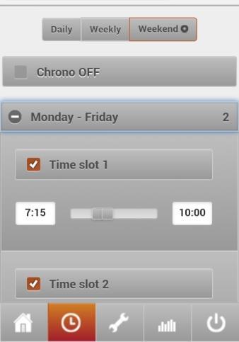
32 7.3.3 CHRONO This menu allows scheduling boiler running hours. Press Enable CHRONO for enabling/disabling chrono function. Enabled function Disabled function To select the desired CHRONO program, press on one of these options: - Enable daily mode : Individual schedule for each day of the week - Enable weekly : The same schedule from Monday to Sunday - Enable week-end : Two schedules: from Monday to Friday and from Saturday to Sunday Monday Tuesday Wednesday Thursday Friday Saturday Sunday From Monday to Sunday From Monday to Friday Saturday and Sunday In each option up to three ON/OFF time lapses can be set. Examples: Press on the left right arrows of the first line to scroll between the three programming options available: daily mode, weekly, week-end Press on the left right arrows of the second line to scroll days or group of days of the week, according to the Programming modality selected before LOAD This menu allows loading manually the burner plate from the auger To enable the auger select ON. To stop the auger, select OFF. Manual load is allowed only if the system is OFF 32


.")


33 7.4. CUSTOMIZATION MENU (INSTALLER) KEYBOARD SETTING. This menu allows setting time and date, as well as language DISPLAY/KEYBOARD MENU. This option allows setting the display brightness SYSTEM MENU. This menu allows entering into the Technical Menu. The access is protected by password (default password: 0000). The user must not modify the content of this menu. Only the installer or a Service Agent are allowed to modify the content of this menu. WES refuses to accept any responsibility in the event that unauthorized personnel enter in this menu. Auger Auger 2 Fan 1 Fan 2 Fan 3 Customization Customization Thermostats Extinguishing Th Timer Default settings Enables Customization Delta Pressure sensor Vacuum regulator Lambda Counters Customization Outputs tests Default parameters 33


34 System menu Description 1 Auger Allows setting Auger ON seconds from the total Auger Period 2 Auger 2 Allows setting Auger2 ON seconds from the total Auger2 Period 3 Fan 1 Allows setting Combustion Fan 1 working values 4 Fan 2 Allows setting Combustion Fan 2 working values 5 Fan 3 Allows setting Exhaust Fan working values 6 Thermostats Allows setting several thermostats working values 7 Extinguishing Th Allows setting Extinguishing thermostat working values 8 Timer Allows setting working time associated to the different system stages 9 Default Settings Allows setting default parameters 10 Enables Enables/Disables different functions 11 Delta Allows adjusting delta temperature and several thermostats hysteresis 12 Pressure sensor Allows setting Pressure sensor threshold 13 Vacuum Regulator Allows setting the parameters needed for adjusting the speed of the exhaust fan in the presence of a vacuum sensor 14 Lambda Allows setting the parameters for running the boiler under Lambda Regulator 15 Counters Allows setting the counters for the system diagnose 16 Outputs Test Allows a manual test of the different outputs from the touch screen 17 Default parameters Resets factory settings The explanation for each parameter and its default value can be found of section 13.- CONTROL PARAMETERS. These parameters are factory preset, and can be modified only under manufacturer surveillance. There are other parameters subject to be modified by the installer, depending on the type of installation. These are described in the section 8.- COMMISSIONING. MENÚ 15 COUNTERS. Allows setting the counters for the system diagnose. This menu shows the following counters: Submenu Total time Functioning time Run Mode time Ignitions Nº Failed Ign. Nº Errors Nº Cleaning Nº Cleaning 2 Nº Counters reset Description Boiler feeding total time Boiler running total time: time into which at least one fan is working Boiler actual heating time: time into which heating is effectively produced (Run/Modulation) Total number of ignition attempts Failed number of ignition attempts Total number of errors Total number of burning plate cleanings Total number of heat exchanger cleanings Reset all counters 34
35 Error list: shows a list with the most recent errors. The outputs test menu is detailed in the following chapter 8. COMMISSIONING 8. COMMISIONING. The Commissioning of this appliance must be carried out by an Authorised Service Agent. This is an essential condition for the keeping the warranty of this appliance. Check that all instructions given in the 5.-Hydraulic installation and 6.-Electrical connections chapters have been followed WATER FILLING. In locations with hard water (>25ºfH, >250 ppm mg/l, >17.54ºe), the heating water must be softened. It avoids the formation of limescales which can endanger the correct performance not only of the boiler, but also of the rest of components (pumps, valves ) Fill the circuit slowly with cold water, having the air vent opened, until a 1.5 bar pressure is reached BOILER PARAMETERS SETTING. System Menu Password 1 Er09 29/09/ :29 2 Er16 23/09/ :34 3 Er16 23/09/ :29 9 DEFAULT SETTINGS (Shaded FACTORY DEFAULTS) Parameter Value Description P35 P66 Plumbing configuration (Default settings) RS485 configuration (Default settings) 0 Heating 2 Heating (Pump) + DHW Tank (3W-valve) 3 Heating (Pump) + DHW Tank (Pump) 4 Inertial puffer 0 Disabled 1 Enabled. Only if lambda probe is installed. A07 Sets room thermostat (Enables) (See section 6.4) Room thermostat disabled. The boiler regulates with the flow temperature. Ambient thermostat is used to switch the boiler from RUN mode to STANDBY mode then the setpoint is reached. Ambient thermostat is used to switch off the circulation pump when the setpoint is reached. Ambient thermostat is used to switch off the boiler when the setpoint is reached. Ambient thermostat is used to switch the boiler from RUN mode to MODULATION mode then the setpoint is reached. A60 Set function double temperature setpoint (Enables) 0 Disabled 1 Enabled for plumbing configuration P35=2, P35=3 35

 FAN 2 (%) FAN 3 (%) AUGER 1 (burner, ON/OFF) AUGER 2 (ashes, ON/OFF) Igniter (ON/OFF) Pump (ON/OFF) 3")
36 6 THERMOSTATS Allows the setting of several thermostats The boiler is supplied with the most usual temperature parameters for the correct operation of the boiler. However, you can change various parameters such as the maximum and minimum temperatures of the boiler, the maximum and minimum temperatures of the DHW tank, activation temperature of the anti-ice temperature, etc. See full listing in section 13. LIST OF CONTROL PARAMETERS THERMOSTATS. 16 OUTPUTS TEST Allows a manual test of the different outputs when the boiler is OFF FAN 1 (%) FAN 2 (%) FAN 3 (%) AUGER 1 (burner, ON/OFF) AUGER 2 (ashes, ON/OFF) Igniter (ON/OFF) Pump (ON/OFF) 3 way-valve (ON/OFF) Output 1. Fire/smoke damper actuator (ON/OFF) Output 2. Exchanger cleaning solenoid valve (ON/OFF) Output 3. Burner plate cleaning actuator (ON/OFF) Output 4. Hopper/silo auger motor (ON/OFF) Output test lasts 60 seconds max. After that, the boiler returns to its previous mode FIRST PELLET LOAD. First, it is necessary that the auger external silo is filled with pellets so that it is ready to supply the boiler. To do this, perform the OUTPUTS TEST (SYSTEM MENU OUTPUTS TEST OUTPUT 4) as many times as necessary for the auger begins to supply pellets towards the boiler. After this step, it will be necessary to do the first pellet load, choosing Load option from the Settings menu. This option activates the feeding auger of the boiler. For stopping the pellet load, pres OFF or wait 60 seconds. Manual load is allowed only if the system is OFF. Repeat manual load until the burner plate has fuel enough. Keep the manual load until there is enough pellets in the combustion plate. Repeat operation if necessary. 36
37 37

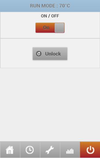
38 8.4. TURNING THE BOILER ON/OFF. UNLOCK. The boiler is electrically supplied via a two pole isolation switch with voltage indicating light Hold the PROGRESS. icon for 3 seconds until an acoustic signal is heard. The display will show IGNITION IN The boiler will command automatically the performance of all its components, following the current settings. For turning off the boiler (even in case of emergency stop), hold the signal is heard. The display will show EXTINGUISHING IN PROGRESS. icon for 3 seconds until an acoustic In running mode, if the boiler detects an error, it will enter in EXTINGUISHING mode, and once this process ends, it remains in BLOCK mode. To unlock, hold the icon for 3 seconds until an acoustic signal is heard. The display will show OFF MANUAL SELECTION POWER. Settings Power Thermostats Summer-Winter Chrono Load The boiler is supplied with automatic power modulation operation, but in the commissioning may be interesting to select the manually operating power. This is controlled with the parameter A05 (System Menu Enables). - A05 = 0: Manual selection of power. - A05 = 1: Caldera automatically modulates. After changing the parameter A05, in the Settings Menu will appear the option Power, where you can select the chosen power BOILER AND BUFFER TEMPERATURE SETPOINT. The heating water set point is set as described in That menu shows how to set both boiler and buffer thermostats set points WINTER-SUMMER This menu allows choosing WINTER/SUMMER operating mode. 38
 In Summer mode, when the DHW set point is reached, the boiler will go to STANDBY mode. 8.")
39 In Winter mode, there is priority for Domestic Hot Water (DHW). When the DHW set point is reached, the boiler returns to its previous state (RUN or STANDBY) In Summer mode, when the DHW set point is reached, the boiler will go to STANDBY mode RESET SERVICE Pressing RESET SERVICE, the ash drawer cleaning interval is reset. This time is defined in the parameter T70. Once this time is done, the display will show a message to remind the user the need for cleaning the ash drawer. By default, this parameter is set at 240 hours. The hours counter increases only when the boiler is in RUN mode and MODULATION mode. 9. BOILER OPERATION 9.1. CIRCULATION PUMP CONTROL The boiler controls the circulation pump of the following ways: First start: To increase the speed of heating water in the boiler, the pump starts when the water temperature of the boiler exceeds 35 C. Operation safety: Regardless of the setting parameter A07, when the boiler temperature exceeds 72 C, the boiler keeps the pump on FANS CONTROL The boiler incorporates a fan to provide combustion air (FAN 1) and an exhaust fan in charge of generating the necessary depression in the combustion chamber (FAN 3). Regulation FAN 1 is carried out by the programming introduced in the boiler, in which the mode of functioning of the fan is determined in the following phases: Ignition - Stabilization - Power 1 to 5 - Second Ignition - Standby - Extinguishing - Cleaning The FAN 3 operates automatically to keep the depression set points in the combustion chamber, in the following phases: Ignition - Stabilization - Power 1 to 5 This depression set point, is measured by a sensor located in the front of the boiler, behind the metal plate which protect the electrical circuits. Combustion chamber (tube) Room (without tube) When the boiler incorporates the accessory module LAMBDA, is the lambda probe which determines the rate of operation of the FAN 1 to obtain the desired percentage of oxygen in the flue gas. 39


40 9.3. AUGERS. The boiler incorporates an auger driven by a gear motor, to introduce the pellet into the burner. The auger regulation is managed by the program introduced in the boiler, which determining its time of actuation in the following phases: Ignition - Stabilization - Power 1to 5 - Second Ignition - Standby At the rear of the boiler, the electrical connection of the hopper auger (not supplied with the boiler) it is provided. The operation of the external auger is carried out via the pellet detection sensor. WES supplies different models of external augers adapted to the boiler. In the case of installing an auger not supplied by WES, the parameter T23 should be regulated to prevent error in the boiler due to lack of pellets ( System Menu Password Times T23). - T23: Delay in stopping the external auger once detected pellet (by default 2 sec.). If the external auger provides less of pellet than burner auger, T23 has to be increased. The maximum lack of pellet time until the boiler goes into alarm is 60 sec. (parameter T24) FIRE/SMOKE DUMPER ACTUATOR. The boiler incorporates a dumper actuator with return spring that works as smoke and flame security device. The boiler governs the opening or closing of the dumper actuator according to the state of the boiler IGNITION MODE In the IGNITION mode there are the following phases: Display Phase Description Time CHECK UP Open dumper actuator Open the pellet feed valve. 60 sec. Check Up Check the system 10 sec. Preheating Preheating of the ignition element. 90 sec. Pellet preload in combustion plate. Loading IGNITION (Variable depending on the model) T03 Fix Ignition First phase of the electric ignition. 600 sec. Variable Ignition Second phase of the electric ignition (5 attempts maximum) 300 sec. STABILIZATION Stabilization Flame stabilization phase 300 sec. RUN Run Normal operation. Power modulation. The Ignition element switch off once it enters in the VARIABLE IGNITION phase and the temperature in the combustion chamber is above 70 C. The STABILIZATION phase begins being under VARIABLE IGNITION and the temperature of the combustion chamber exceeds 85 C. 40 When it detects lack of pellet, the LED swicht off and sends a signal to the external auger for transporting pellet to the boiler. When the sensor detects the existence of pellet, the yellow LED lights and the external auger stops. Ignition-Stabilization-Power 1 to 5 - Second Ignition OPEN Standby - Extinguishing CLOSED Error - Block CLOSED Any alarm detected by the boiler, or in case of power failure, the dumper actuator automatically closes in tight manner the pellet supply duct, thereby preventing back of fire and flue gas.
41 RUN phase begins when the temperature of the combustion chamber exceeds 150 C, regardless of the stage where you are at that moment RUN and STANDBY MODE. In RUN mode, the boiler automatically modulates the working power to reach the temperature setpoint. The modulation range is 5 steps power (P1 to P5), and its operation is determined by the configurable parameter D08 (System Menu DELTAS D08), the default is 12. When the boiler temperature is lower than (temperature setpoint - D08), the boiler operates at full power (P5). From then it modulates its power, changing every 3 C (D08/4). Examples: Tª setpoint = 50 C Tª setpoint = 75 C D08 = 12 C D08 = 12 C Boiler Temp. Power Boiler Temp. Power < 38 C P5 < 63 C P5 38 C - 40 C P4 63 C - 65 C P4 41 C - 43 C P3 66 C - 68 C P3 44 C - 46 C P2 69 C - 71 C P2 47 C - 50 C P1 72 C - 75 C P1 D8 parameter values must be multiples of 4 (D08 = 4, 8, 12, 16,...). The higher the value, the boiler takes longer to reach the setpoint, but instead it will work more regular and lower consumption because it will work most of the time at different powers of its maximum power. 41
42 The lower the value, the faster boiler reaches the set temperature, but if the heating system has low inertia, the boiler can reach excessive temperatures. When the boiler reaches the setpoint temperature, the boiler goes to MODULATION mode. When the boiler exceeds 2 C (D10) the temperature setpoint, the boiler is switched to STANDBY mode. In STANDBY mode the pellet feed valve is closed, so in this mode the boiler does not consume any fuel and the temperature of the combustion chamber starts to drop. In STANDBY mode, if the boiler temperature drops below (setpoint-2 C (D10)) (i.e. there is request for heating or DHW), the boiler out of STANDBY mode and enters in NORMAL mode, modulating their power from the minimum power (P1). Run Modulation Standby Power modulation The boiler setpoint has been reached The boiler temperature is 2 C over the setpoint In STANDBY mode, if the temperature of the combustion chamber down below 100 C, the boiler will make the final cleaning and remain in STANDBY mode. If the heat demand returns, the boiler will start automatically the full cycle, including the PRELOADING phase. If the heat demand returns when the temperature of the combustion chamber is above 150 C, the start is performed omitting the ignition process, so it will enter directly in RUN mode, without performing the precharge phase EXTINGUISHING and BLOCK MODE. 42
43 EXTINGUISHING mode is activated when the boiler is turned off manually or by scheduling. In these cases, the boiler ends in OFF mode. EXTINGUISHING mode is also activated when the boiler detects an alarm. In these cases, the boiler ends in BLOCK mode and unlock necessary (see section 8.4). After starting the EXTINGUISHING mode, the boiler can be automatically out of this state in the following cases: - After a power failure between 1 and 60 minutes, if the boiler was ON. - Manually by pressing the ON/OFF button on the boiler. It starts the IGNITION cycle DHW PRODUCTION The E-COMPACT TWIST boilers are planned for production of DHW through a DWH Tank (see section 8. - Default Settings), parameters P35=2 or 3, and A60 = 1 (System Menu Enables). With these parameters, the behaviour of the boiler is as follows: - If there is no demand for DHW, the boiler works with the set point manually entered (e.g. 50 C). - If there is demand for DHW, the boiler automatically changes its set point to 70 C, to satisfy as quickly as possible the DHW set point manually entered (30-60 C) (See section Boiler and Buffer temperature set point) - Once satisfied the demand for DHW: WINTER MODE: the boiler returns to its previous state (RUN or STANDBY) SUMMER MODE: the boiler is switched to STANDBY AUTOMATIC CLEANINGS The boiler carries out various cleaning automatically: - PERIODIC CLEANING. Combustion plate cleaning by air. - CLEANING 1. Mechanical cleaning of combustion plate. - CLEANING 2. Final cleaning (mechanical for the combustion plate and by water in the exchanger tubes). PERIODIC CLEANING consists in putting to the maximum speed the combustion fan for a short period of time (parameters T07 and T08). CLEANING 1 consists in putting the cleaning nails into the plate to an intermediate position and simultaneously the plate begins to rotate. Thus the ashes are swept to the ash drawer. The frequency and duration of the cleaning is done differently depending on the model of the boiler (T27 and T28 parameters). CLEANING 2 is performed in these circumstances: - Boiler in EXTINGUISHING mode and temperature of the combustion chamber below 80 C (TH01). After the cleaning, the boiler is in OFF mode. - Boiler in STANDBY mode and temperature of the combustion chamber below 100 C (TH28). After the cleaning, the boiler remains in STANDBY mode. The final cleaning comprises a mechanical cleaning of the combustion plate, similar to the CLEANING 1 described above, but in this case the nails rotate to the end position, so that, they also clean the exit holes of the primary combustion air. 43
44 The positioning of the nails is controlled by the limit switches of the linear actuator located on the burner. During CLEANING 2, cleaning exchanger tubes solenoid opens and allows the water flow for a time T54 in seconds (configurable parameter System Menu Time T54). Water flows inside the tubes and it is evacuated to the drain. In the case of BCH-100 model, the activation of the solenoid valve is associated to the CLEANING CLEANING AND MAINTENANCE Read carefully the following instructions in order to avoid unnecessary risks. The internal cleaning of the boiler must be performed at least once a year by qualified personnel. The metallic parts must be mechanically cleaned with a NON METALLIC brush. Risk of burns. The servicing must be done with the boiler OFF and cold. Warning: even in these conditions ashes may still be hot. Risk of electric shock. The servicing must be done with the boiler OFF. According to the legislation, it is mandatory to keep a servicing logbook. E-COMPACT boilers are automatic boilers, but for safety, smooth performance and for extending its useful life, the following maintenance operations, as legislation specifies, are necessary: TASK Check the status of pellet storage Visual inspection of the boiler Ash cleaning and removal Review the security elements Cleaning the burner Checking and cleaning, if necessary, smoke circuit, boiler flue circuit, flue gas pipe and chimney Checking tightness seal between burner and boiler Review the status of thermal insulation Review automatic control system Review the expansion vessel Review of water treatment systems Review DHW preparation system Checking for pipes tightness PERIODICITY weekly weekly monthly monthly yearly yearly yearly yearly yearly yearly yearly yearly yearly 44
45 10.1. COMBUSTION CHAMBER AND HEAT EXCHANGER TUBES CLEANING. Access to the top of the boiler removing the upper housing and insulation. Remove the thermocouple and the boiler cover by releasing the four nuts. Before cleaning with water, aspires the ash accumulated on top of the boiler and inside the combustion chamber. Check the effectiveness of water cleaning system by performing an OUTPUT TEST (Output2) as described in section 8.2. In case some Injector were blocked or flow water is diverted, replace the threaded injector by a new one. Remove the cleaning system through the loose nut. Remember to shut off the water supply before removing the toroid. The flue tubes are cleaned individually introducing inside each tube a 25 mm diameter water hose connected to the water network. Let the water run for a few seconds inside each tube to flush any solid waste. Cleaning water with waste are discharged through the condensate drain trap BURNER CLEANING. Remove the supply hose pellet and the burner cover to access the screw of the ignition resistance. 45
46 - Remove the heater element to release the burner grate. - Remove the grate by the front door. - Aspire the ash. - Clean the burner grate. To remove the burner inside the boiler proceeds as follows: Remove the fixing screws and remove the burner by the lateral door. Please assemble in reverse order. 46


47 The heater element must be correctly positioned and fixed with the screw. Check the correct closure of the connecting piece to the burner of the secondary air nozzle. 11. ASH REMOVAL The ash volume depends on the number of boiler running hours, as well as the quality of the used pellet. Ash removal must be carried out complying local legislation in force. Pay attention during emptying the ashes, as they may still be hot. In this case you must wait for them to cool, since there is risk of fire. Protective equipment: gloves, goggles, mask. Ashes are a good thermal insulator. It is advisable not completely empty the drawer The boiler will show the message "CLEANING" in the display to indicate empty signal of the ash box. This message is displayed after a time T70 programmable according to the boiler output. After emptying the drawer, enter User Menu Reset Service. Thus the counter (see section 8.8) restarts. The boiler has enough space to store the ash produced for more than a month of normal operation, so that cleaning and removal of ashes are to be carried out once a month. The BCH-25 /... / 100 models have an automatic system that extracts the ashes from the burner bottom and place them in an ash box, which can be emptied without stopping the boiler. To remove the ash box from its support base, first enter the bottom lock sheet. THIS SHEET MUST BE OUT IF THE BOILER IS RUNNING During operation of the boiler, the base of the ash box should be filled with ashes to prevent the exhaust fan can absorb air through the auger. In the commissioning of the boiler, when 47
48 there are no ashes produced, it is necessary to fill the base of the case with the bag of vermiculite supplied with the boiler. 48
49 12. LIST OF ERRORS. CAUSES AND ACTIONS TO BE TOKEN. Code Er01 Er03 Er04 Er05 Causes an actions to be taken Error activation Safety thermostat The water temperature in the boiler has reached 100 C. The boiler enters into EXTINCTION mode. Let the boiler to cool and make a visual inspection. A manual reset is needed, by pressing until you hear a "click" the switch located under the cap next to the touch screen. This reset will occur when the boiler temperature has dropped below 90 C. Possible causes and actions to be taken: - No water flowing through the boiler circuit. Check manual valves and filters in the circuit. Check the connection and operation of the pump. Contact your installer. - Boiler temperature probe not connected, badly placed or defective. Check the placement and connection of the probe. Contact Service Agent. - Existence of air in the boiler circuit. Check the automatic air vent. - Heating circuit without pressure. Contact your installer. Extinguishing not foreseen for low temperature at the combustion chamber The boiler moves to EXTINCTION mode because of low temperature at the combustion chamber. Possible causes and actions to be taken: - Lack of pellets in the auger. Check for fuel. Make a manual auger load (LOAD command in user menu). Contact your installer. - Pellet feed auger motor stopped. Check the power supply. In case of motor failure, contact your installer or Service Agent. - Igniter failure. Check resistance (211 Ω / 230 V). In case of failure contact your installer or Service Agent - Reading Error at combustion chamber temperature probe. Verify that flame is placed in the combustion chamber. If so, combustion chamber temperature probe is not measuring correctly. Stop the boiler and contact your installer or Service Agent. - Combustion chamber temperature probe no connected, badly placed, or defective. Check the placement and connection of the probe. Stop de boiler and contact your installer or Service Agent Water over-temperature The water temperature in the boiler has reached 95 C. The boiler enters into EXTINCTION mode. Let the boiler to cool and make a visual inspection. Possible causes and actions to be taken: - No water flowing through the boiler circuit. Check manual valves and filters in the circuit. Check the connection and operation of the pump. Contact your installer. - Boiler temperature probe not connected, badly placed or defective. Check the placement and connection of the probe. Contact Service Agent. - Existence of air in the boiler circuit. Check the automatic air vent. - Heating circuit without pressure. Contact your installer. Combustion chamber over-temperature The combustion chamber has reached 890 C. The boiler enters into EXTINCTION mode. Possible causes and actions to be taken: - Faulty performance of auger / incorrect settings. Stop the boiler and contact your installer or Service Agent. Flue gas over-temperature in chimney SECURITY message appears on the display. The flue gas sensor exceeds 100 C. Er09 Er10 Er11 Possible causes and actions to be taken: - The exchanger tubes cleaning system by water is not being effective. Check the valves located upstream of the solenoid cleaning valve. Stop de boiler and contact your installer or Service Agent Low water pressure Water pressure is below 0.5 bar (500 mbar). Possible causes and actions to be taken: - Water leakage in the heating circuit. When the circuit is cold, re-pressure and purge the circuit. If the pressure drops again contact your installer. High water pressure Water pressure is over 3 bar (3000 mbar). Possible causes and actions to be taken: - Safety 3 bar pressure relief valve not installed or defective. Contact your installer. - Expansion vessel defective or improperly sized. Contact your installer. Real time clock error Possible causes and actions to be taken: - Battery failure of the control board. Contact your installer or Service Agent. 49
50 50
51 Er12 Er15 Er16 Er18 Er22 Er34 Er35 Ignition failed The boiler has not been able to ignite a flame after several programmed attempts. Possible causes and actions to be taken: - Igniter failure. Check resistance (211 Ω / 230 V). In case of failure contact your installer or Service Agent - Absence of pellets in the combustion plate. Make a manual load by selecting LOAD at User menu. Air obstruction at primary / afterburning air conducts. Clean conducts. Lack of voltage The boiler has stopped working because of power failure. Possible causes and actions to be taken: - Unlock the boiler and return to normal operation. RS485 lambda probe communication error The main control board does not communicate with the board of the lambda probe. Possible causes and actions to be taken: - Check both boards voltage (LEDs ON). Faulty fuses. Contact your installer or Service Agent. - Check RS485 communication cable. For replacement contact your installer or Service Agent. Extinguishing for lack of pellet The sensor pellet detects unavailability of pellet for feeding the boiler. Possible causes and actions to be taken5 - Fault in auger/vacuum feeding system. Contact your installer or Service Agent. - Sensor pellet faulty. Contact your installer or Service Agent. Lambda regulator error Lambda probe regulator has detected an error and blocks the boiler. Possible causes and actions to be taken: For disabling lambda regulator error warning modify the parameter P60 = 0 (System Menu Lambda Control P60). Contact your installer or Service Agent. Depression below the minimum threshold Combustion chamber depression has dropped below preset minimum threshold (15 Pa). Possible causes and actions to be taken: - Fault in smoke exhaust fan. Contact the Service Agent. - Pressure sensor defective. Contact the Service Agent. - Chamber inspection door opened. Close the door. - Pressure sensor or its tubule incorrectly installed. Connect the tubule / place the sensor in the proper position. Depression above the maximum threshold Combustion chamber depression has risen over preset maximum threshold (200 Pa). Possible causes and actions to be taken: - Pressure sensor defective. Contact the Service Agent. - Excessive draft in the chimney. Place a flue draft regulator. Contact the Service Agent. NOTE: Errors EL00 to EL08 correspond to boilers equipped with lambda probe. Refer to the manual provided with the lambda probe. Other error messages End Pellet Lack of pellet error The sensor pellet detects unavailability of pellet for feeding the boiler. Prob Service Possible causes and actions to be taken: - The boiler runs out of fuel. Ask for more fuel to your supplier - Fault in feeding pellet to the burner. Check the feeding system (auger or vacuum) Temperature probe error When CHECK-UP phase, if one or more probes show 0 C value, open or short circuit. It does not cause an error; it is only a display message. Possible causes and actions to be taken: - Check probes connection. In case of faulty probe, request replacement by contacting the Service Agent Servicing message The interval (240 hours in RUN mode) since last emptying of the ash box is fulfilled. Possible causes and actions to be taken: - Empty the ash box. Restart the counter doing the RESET SERVICE in the user menu. 51
52 13. LIST OF CONTROL PARAMETERS. Code Value Description Default value ENABLE 0 Manual management of the combustion system A Automatic management of the combustion system 0 External room thermostat input is disabled External room thermostat is used to switch boiler to STANDBY mode when the set point 1 is reached. External room thermostat is used to switch off the circulation pump when the set point A07 2 is reached. 0 3 External room thermostat is used to switch off the boiler when the set point is reached External room thermostat is used to switch the boiler to MODULATION mode when the 4 set point is reached. A10 1 From Extinguishing state it s possible to go directly to CHECK UP 1 A13 1 If boiler temperature is higher than (setpoint+2 C) after time T55, the boiler enters into STANDBY mode. A14 1 Enable Pressure Sensor Error management 1 A16 1 Enable Power Changing delay 1 A20 0 Water pressure Sensor Configuration Type A 0 A26 0 Exit from STANDBY if there aren t the conditions 0 A27 1 Extinguishing in STANDBY enable. TH28 and T13 parameters are used. 1 A29 1 Exit from STANDBY if a sanitary water demand occurs enabled. 1 A30 1 Vacuum Regulator on Exhaust Fan Speed Enabled. 1 A60 1 Double temperature set point function enabled for schemes with P35=2, 3. 1 DEFAULT SETTINGS P02 Maximum number of ignition attempts 5 P03 Number of power steps 5 P04 Number of combustion recipes 1 P05 Auger 1 period s/model P09 Pellet level sensor configuration 0 P14 Fan 1 min speed 20 P27 Fan 3 min speed 20 P35 Hydraulic configuration (see section 5.3) 2 P61 OUT1 configuration. Fire/smoke dumper actuator. 1 P62 OUT2 configuration. Cleaning 2 (final cleaning) 13 P63 OUT3 configuration. Cleaning 1 (burner) 4 P64 OUT4 configuration (external auger) 2 P66 0 RS485 communication with lambda module disabled 1 RS485 communication with lambda module enabled P78 1 Safety function with smoke probe enabled. 1 THERMOSTATS (Thermostat hysteresis are shown as IHxx in menu) TH01 Boiler off 80 (-2) TH02 Ignition resistance off 70 (+2) TH03 Pre-Extinguishing for low chamber combustion temperature 100 (-2) TH06 Move to STABILIZATION Mode 85 (+2)
53 TH07 Move to MODULATION Mode 850 (+20) TH08 Flue gas Safety 890 (+20) TH09 Bypass Ignition (move to RUN) 150 (+5) TH18 Anti-freeze 5 (-0) TH19 Circulation pump ON 35 (+2) TH20 DHW min temperature 40 (+2) TH21 DHW max temperature. Automatic set point for high temperature operation. 72 (-2) TH24 Boiler water temperature 60 TH25 Boiler safety thermostat 95 (+2) TH26 Boiler min range thermostat 25 TH27 Boiler max range thermostat 80 TH28 Extinguishing exhaust temperature in STANDBY 100 (-5) TH29 Buffer thermostat 45 (±2) TH30 Differential thermostat 3 (±1) TH35 Extinguishing exhaust temperature Power TH36 Extinguishing exhaust temperature Power TH37 Extinguishing exhaust temperature Power TH38 Extinguishing exhaust temperature Power TH39 Extinguishing exhaust temperature Power TH55 Min. value for buffer thermostat 30 TH56 Max. value for buffer thermostat 60 TH78 Flue gas safety temperature 100 (+2) DELTA TEMPERATURE D01 Delta temperature to exit from STABILIZATION phase (to add to TH06) 50 D08 Delta temperature for power modulation in proportional combustion management 8 D10 Delta temperature for moving from MODULATION to STANDBY 2 TIME T01 Check-up Cleaning time (air sweeping) 10 s. T02 Preheating phase 90 s. T03 Auger preload s/model T04 Fixed ignition 600 s. T05 Variable ignition 300 s. T06 Stabilization 300 s. T07 Periodic cleaning repetition (air sweeping) 60 m. T08 Periodic cleaning duration 15 s. T09 Safety thermostat delay 60 s T10 Safety pressure switch delay 60 s. T11 Exit from STANDBY delay 10 s. T13 Minimum Extinguishing time at Standby 60 s. T14 Pre-Extinguishing 900 s. T15 Safety Extinguishing 60 s. T16 Final cleaning time 60 s. T17 Power shifting delay 30 s. T18 Power shifting delay at IGNITION 30 s. T22 Entering time delay at STANDBY 10 s. T23 Pellet tank loading time after minimum level signal 2 s. T24 Pellet tank loading time for reaching the minimum level 60 s. 53
54 T25 Delay on closing from pellet sensor signal 0 s. T26 Delay on opening from pellet sensor signal 0 s. T27 Cleaning system delay on RUN mode 60 m. T28 Cleaning system time 20 s. T50 Fired/smoke dumper actuator open time 60 s. T54 Cleaning engine 2 ON at the end of Extinguishing 20 s. T55 Waiting time to go in Standby from Modulation 10 s. T68 Exit delay from Security function 10 s. T70 Cleaning Message Timer 240 h. WATER PRESSURE SENSOR THRESHOLD S01 Pressure sensor minimum threshold 500 mbar S08 Pressure sensor maximum threshold 3000 mbar COMBUSTION CHAMBER DEPRESSION SENSOR PR 00 IGNITION mode set point 60 Pa PR 01 STABILIZATION mode set point 30 Pa PR 02 Power 1 set point s/model PR 03 Power 2 set point s/model PR 04 Power 3 set point s/model PR 05 Power 4 set point s/model PR 06 Power 5 set point s/model PR 20 IGNITION mode depression delta 3 Pa PR 21 STABILIZATION mode depression delta 3 Pa PR 22 Power 1 depression delta 3 Pa PR 23 Power 2 depression delta 3 Pa PR 24 Power 3 depression delta 3 Pa PR 25 Power 4 depression delta 3 Pa PR 26 Power 5 depression delta 3 Pa PR 70 Min depression threshold alarm 5 Pa PR 90 Max depression threshold alarm 200 Pa T69 Depression sensor. Regulation time 5 s. T70 Depression sensor. First regulation waiting time 60 s. T80 Delay after Depression Alarm 60 s. PARAMETER LIST OF LAMBDA REGULATOR Parameter Description Value TH50 Lambda ON thermostat set 200 C (± 4) TH51 Lambda ON thermostat min. 200 C (± 4) TH52 Lambda ON thermostat max. 850 C (± 20) P66 Communication RS485 with Lambda module disabled 0 Communication RS485 with Lambda module enabled 1 T62 O2 monitoring interval 10 sec. T63 Maximum time regulator out of range 10 sec. T64 Delay for the first regulation 20 sec. P58 Outputs order management 13 P60 Lambda regulator error management 0 / 1 / 2 P67 FAN 1 regulation direction 0 54
55 P68 FAN 2 regulation direction 0 P69 Auger regulation direction 1 P70 Outputs regulation management 1 UC81 FAN 1 regulation step 1% US81 FAN 2 regulation step -- C81 Auger regulation step 0,1 sec. The parameters that define the behaviour of the auger and fans are: Burner Ashes Auger Auger FAN 1 FAN 2 FAN 3 Ignition C01 C21 UC01 US01 UA01 Stabilization C02 C22 UC02 US02 UA02 Power 1 C03 C23 UC03 US03 UA03 Power 2 C04 C24 UC04 US04 UA04 Power 3 C05 C25 UC05 US05 UA05 Power 4 C06 C26 UC06 US06 UA06 Power 5 C07 C27 UC07 US07 UA07 Second Ignition C08 C28 UC08 US08 UA08 Standby C09 C29 UC09 US09 UA09 Extinguishing -- C30 UC10 US10 UA10 Periodic Cleaning UC11 US11 UA11 Ignition. Min. speed vacuum regulator UA41 Ignition. Max. speed vacuum regulator UA42 Power Burner Auger Speed min. / max % O2 FAN 1 FAN 2 Value TOLERANCE P1 C43 / C63 UC43 / UC63 US43 / US63 oo3 o23 P2 C44 / C64 UC44 / UC64 US44 / US64 oo4 o24 P3 C45 / C65 UC45 / UC65 US45 / US65 oo5 o25 P4 C46 / C66 UC46 / UC66 US46 / US66 oo6 o26 P5 C47 / C67 UC47 / UC67 US47 / US67 oo7 o27 If the lambda probe kit is installed, please see the manual provided with lambda probe kit. 55
56 NOTES: 56

57 Head Office: WoodCo Energy SA, Rte de Courgenay 38, 2900 Porrentruy, Switzerland. t: WoodCo Energy Ireland Unit D Cahir Business Park, Cahir, Co. Tipperary, Ireland. t: w: e: info@woodco-energy.com 57
INSTALLATION AND OPERATING INSTRUCTIONS BIOCLASS HM
 INSTALLATION AND OPERATING INSTRUCTIONS BIOCLASS HM Thank you for choosing a DOMUSA TEKNIK heating boiler. Within the product range offered by DOMUSA TEKNIK you have chosen BioClass HM model. With a suitable
INSTALLATION AND OPERATING INSTRUCTIONS BIOCLASS HM OD (FOR EXTERNAL USE)
") INSTALLATION AND OPERATING INSTRUCTIONS BIOCLASS HM OD (FOR EXTERNAL USE) Thank you for choosing a DOMUSA TEKNIK heating boiler. Within the product range offered by DOMUSA TEKNIK you have chosen BioClass
INSTALLATION AND OPERATING INSTRUCTIONS BIOCLASS HM OD (FOR EXTERNAL USE) Thank you for choosing a DOMUSA TEKNIK heating boiler. Within the product range offered by DOMUSA TEKNIK you have chosen BioClass
EasyTech.One Temperature Controller for Pellet Burner
 EasyTech.One Temperature Controller for Pellet Burner Burner 1 INTRODUCTION... 3 2 ELECTRICAL CONNECTIONS... 3 3 CONTROL PANEL: USE AND FUNCTIONS... 5 3.1 LED... 5 3.2 BUTTONS... 5 3.3 ALARMS... 5 3.1
INSTRUCTIONS FOR USE OF COMBINED BOILER INTENDED FOR COMBUSTION OF BOTH PELLETS AND SOLID FUEL ABC COMBO
 INSTRUCTIONS FOR USE OF COMBINED BOILER INTENDED FOR COMBUSTION OF BOTH PELLETS AND SOLID FUEL ABC COMBO .Technical specifications Boiler power DESCRIPTION Water content in a boiler Required draft Supply
Electronic Pellet Burner Controller NPBC-V3M
 Electronic Pellet Burner Controller NPBC-V3M SOFTWARE VERSION 3.3a/3.2 page of 27 CHANGES IN THE USER MANUAL OR IN THE CONTROLLER'S SOFTWARE Version of the user manual Changes Page 2.2. The software version
EasyTech.Full Temperature Controller for Pellet Stove. Idro
 EasyTech.Full Temperature Controller for Pellet Stove EasyTech.One is a Pellet stoves control system available in Air and Hydro version. Is characterised by: Installing and use simplicity Simple and direct
Electronic Pellet Burner Controller NPBC-V3-1
 Electronic Pellet Burner Controller NPBC-V3- SOFTWARE VERSION 3.2/3. page of 3 CHANGES IN THE TECHNICAL AND USER GUIDE OR IN THE SOFTWARE VERSION Technical and User Guide's version Changes Page 2.8. The
CentroPelet ZV14 TECHNICAL INSTRUCTIONS HEATING TECHNIQUE. for regulation, use and maintenance of pellet stove
 HEATING TECHNIQUE Centrometal d.o.o. - Glavna 12, 40306 Macinec, Croatia, tel: +385 40 372 600, fax: +385 40 372 611 TECHNICAL INSTRUCTIONS for regulation, use and maintenance of pellet stove CentroPelet
USER MANUAL 9kW LILLY PELLET STOVE
 USER MANUAL 9kW LILLY PELLET STOVE Table of Contents.Overview of Stove Parts... 2.Technical Characteristics... 3 3.Important Information... 4 4.Pellet Specification...5 5.Technology... 6 6.Installation...
INSTRUCTION FOR THE USER THC V E OIL BLU
 INSTRUCTION FOR THE THC V E OIL BLU CONTENTS General safety information 4 Precautions 4 Control panel 5 Mode selection 8 User levels 10 Start-up 12 Temporary shutdown 15 Preparing for extended periods
WHE 2.24 / WHE 2.24 FF
 EN Wall-hung gas boilers WHE 2.24 WHE 2.24 FF User Guide 300011777-001-C . Contents 1 Introduction.............................................................................3 1.1 Symbols used...........................................................................................3
OPERATION MANUAL RK-2006LPP AUGER FITTED SOLID FUEL BOILER TEMPERATURE CONTROLLER. Version DC19
 OPERATION MANUAL RK-2006LPP AUGER FITTED SOLID FUEL BOILER TEMPERATURE CONTROLLER Version DC19 1. Application. Controller RK-2006LPP is designed for temperature control of solid fuel fired water boilers
INSTRUCTION MANUAL & SERVICE MANUAL ORLIGNO 400
 INSTRUCTION MANUAL & SERVICE MANUAL ORLIGNO 400 Content 1. Delivery......................................................................... 3 2. Installation and assembly.........................................................
DEVRON SERIES MULTI FUEL FIRED GASIFICATION HOT WATER BOILERS DEVRON-30, DEVRON-40 OPERATION, USE AND MAINTENANCE MANUAL
 DEVRON SERIES MULTI FUEL FIRED GASIFICATION HOT WATER BOILERS DEVRON-30, DEVRON-40 OPERATION, USE AND MAINTENANCE MANUAL Rev A: JUNE 2017 INDEX 1- INTRODUCTION... 3 2- WARNINGS... 3 3- DECLARATION OF CONFORMITY...
Divacondens D Plus Atmospheric condensation wall-mounted boilers, with instant domestic hot water production
 Divacondens D Plus Atmospheric condensation wall-mounted boilers, with instant domestic hot water production THE SIMPLEST SOLUTION FOR A CONDENSING BOILER DIVACONDENS D PLUS is the generator of condensation
VICTRIX 90 VICTRIX 115 Wall-hung condensing boilers for high power
 VICTRIX 90 VICTRIX 115 Wall-hung condensing boilers for high power VICTRIX 90 is the new wall-hung condensing boiler for room heating only, set-up for independent functioning and for that in cascade mode
PELLET BURNER PV 350
 PELLET BURNER PV 350 INSTRUCTION MANUAL v1.1 1 PRODUCT DESCRIPTION...3 2 SAFETY RULES...3 3 WARNINGS...4 4 INSTALLATION INSTRUCTIONS...5 4.1 BOILER REQUIREMENTS...5 4.2 PELLET CONTAINER...6 4.3 INSTALLATION
1 DOCUMENT REVISION CONTROL ELEMENTS... 9
 CONTENTS Contents 1 DOCUMENT REVISION... 8 2 SOFTWARE VERSION... 8 3 BASIC DESCRIPTION... 8 4 CONTROL ELEMENTS... 9 4.1 BASIC DISPLAYS...10 4.2 CONTROL KEYS...11 4.2.1 Rotary button (Press / Turn)...11
So old fashioned... As the combustion chamber is completely room sealed, it does not release any smells and does not dirty.
 ARREDO E BENESSERE So old fashioned... An intelligent choice When on a cold winters night the warm glowing flames of the KALDUS boiler are there to welcome you back home, you will be pleased that you decided
High Performance Electronic Modulation Automatic Cleaning Easy Installation 4 Power Levels: 9,15,25,42kW. Pellet Boilers. Future of Ecological Heating
 Pellet Boilers High Performance Electronic Modulation Automatic Cleaning Easy Installation 4 Power Levels: 9,15,25,42kW Future of Ecological Heating Why choose an Ekoheat boiler? Ekopower is an innovative
INSTRUCTIONS FOR ASSEMBLY, USE, AND MAINTENANCE PELLET STOVE LUCA S/LUKA S8
 WARNING: This user manual is an integral part of the product. It has to be kept and read carefully. EN INSTRUCTIONS FOR ASSEMBLY, USE, AND MAINTENANCE PELLET STOVE LUCA S/LUKA S8 1. Introduction Firstly,
TECHNICAL INSTRUCTIONS USE AND MAINTENANCE
 TECHNICAL INSTRUCTIONS USE AND MAINTENANCE Cm Pelet-set For boilers CentroPlus 25/35 and CentroPlus-B 25/35 (solid fuel and wood pellets fuel firing) TUPSCP-K-11-2016-ENG CONTENTS 1.Introduction 2. Status
USER GUIDE VOGUE COMBI GEN2 C26 C32 C40
 USER GUIDE VOGUE COMBI GEN2 C26 C32 C40 When replacing any part on this appliance, use only spare parts that you can be assured conform to the safety and performance specification that we require. Do not
BIX B-One 100 kw INSTALLATION GUIDE
 BIX B-One 100 kw INSTALLATION GUIDE Dear Customer, We thank you for choosing our product. The Bix B-One 100 Kw is a burner of advanced concept and technology, with a high reliability and construction quality.
USER MANUAL ACQUAHOME 32 B BLU
 USER MANUAL ACQUAHOME 32 B BLU Dear Customer, Thank you for preferring a T heating unit, a modern, high-quality product that is able to guarantee your maximum well-being for a long period of time, with
INSTRUCTION MANUAL OF THE SIEMENS CLIMATIX 2 CONTROL EQUIPMENT
 Instruction manual of the control equipment Program version: 2014-01-17 Benekov 04.00 C L I M A T I X 2-1 - CONTENTS 1. Introduction... 3 1.1. TERMINOLOGY AND ABBREVIATIONS... 3 1.2. NUMBER OF HEATING
Boiler Technical Specifications (2013)
") ACT Bioenergy Boiler Dimensions 0.5-0.85 Million Btu/h (150-250kW) Model CP500 CP600 CP750 CP850 Heat Output in MBtu/h (kw) 510 (150) 610 (180) 750 (220) 850 (250) Height ft (mm) 6 1 (1855) 6 1 (1855)
ACT Bioenergy Boiler Dimensions 0.5-0.85 Million Btu/h (150-250kW) Model CP500 CP600 CP750 CP850 Heat Output in MBtu/h (kw) 510 (150) 610 (180) 750 (220) 850 (250) Height ft (mm) 6 1 (1855) 6 1 (1855)
USERS MANUAL FOR GAS BOILERS
 USERS MANUAL FOR GAS BOILERS PLEASE READ THE MANUAL CAREFULLY: IT CONTAINS IMPORTANT INFORMATION REGARDING SAFETY, INSTALLATION, USE AND MAINTENANCE OF THE APPLIANCE MODELS: NOVADENS 24 NOVADENS 24C NOVADENS
SY250 IDRO 4/8 BUTTONS MANUAL
 SY250 IDRO 4/8 BUTTONS MANUAL Pag. 1 / 44 Summary 1 INTRODUCTION... 4 2 INSTALLATION... 4 2.1 CONNECTIONS... 4 2.2 DIGITAL INPUTS... 7 2.2.1 Safety High Voltage 1... 7 2.2.2 Safety High Voltage 2... 7
USER GUIDE. IMAX XTRA EL kW. For Installation Guide see reverse of book
 USER GUIDE IMAX XTRA EL 320-620kW For Installation Guide see reverse of book When replacing any part on this appliance, use only spare parts that you can be assured conform to the safety and performance
GRANOLA AUT O MATIC Instal ation Use Maintenance
 GRANOLA AUTOMATIC Installation Use Maintenance www.arcacaldaie.com ARCA s.r.l. declines all liability for any imprecisions due to transcription or printing errors. It likewise reserves the right to make
METAL INDUSTRY VRANJE
 METAL INDUSTRY VRANJE st:radnička n-1 PELLET STOVE LUCA S / LUCA S8 WARNING:This user manual is an integral part of the product.it has to be kept and read carefully. INSTRUCTIONS FOR ASSEMBLY, USE, AND
Biomass. Biomass solid fuel boiler range
 Biomass Biomass solid fuel boiler range Biomass Fuelling positive change For more than150 years, Baxi has been at the forefront of heating technology Baxi leads the way with new and pioneering heating
USE AND MAINTENANCE. Cm Pelet-set (60-90 kw) TECHNICAL INSTRUCTIONS
 TECHNICAL INSTRUCTIONS") CENTROMETAL d.o.o. Glavna 12 40306 Macinec Croatia tel: +385 40 372 600; fax : +385 40 372 611 TECHNICAL INSTRUCTIONS USE AND MAINTENANCE Cm Pelet-set (60-90 kw) For boilers: EKO-CK P 70-110 TUPS-90K-09-2015-E-N-eng
CENTROMETAL d.o.o. Glavna 12 40306 Macinec Croatia tel: +385 40 372 600; fax : +385 40 372 611 TECHNICAL INSTRUCTIONS USE AND MAINTENANCE Cm Pelet-set (60-90 kw) For boilers: EKO-CK P 70-110 TUPS-90K-09-2015-E-N-eng
TECHNICAL MANUAL BIOTEC 25 AND BIOTEC 40
 TECHNICAL MANUAL BIOTEC 25 AND BIOTEC 40 2 INDEX INDEX Safety information.......4 Technical data...5 Boiler features...6 Technical information........7 Fuel...... 8 Construction and function...... 9 Hydraulic
STILE BEAUTY AND TECHNOLOGY
 STILE BEAUTY AND TECHNOLOGY STILE, in line with your style Designer White Bordeaux Silver Grey MODEL Nominal input kw Nominal output kw Output to the water min. / max. kw HYDRONIC PELLET FIRE SPACE HEATING
Aqua Balance. AquaBalance TM CONTROL MODULE QUICK START GUIDE LEGEND
 Aqua Balance AquaBalance TM CONTROL MODULE QUICK START GUIDE 10 1 Domestic Hot Water temperature setpoint decreasing button 2 Domestic Hot Water temperature setpoint increasing button 3 Central Heating
i 24, i 30, i 35 combination boilers USER GUIDE For Installation Guide see reverse of book UIN A05 October 2017
 24 1 2 23 3 4 5 20 6 I 19 7 18 8 9 15 14 11 13 12 i 24, i 30, i 35 combination boilers USER GUIDE For Installation Guide see reverse of book i 24 OFF MAX E STATUS BURNER RESET MIN PRE MIN MAX HEAT PREHEAT
.it AQ USER OPERATING INSTRUCTIONS
 .it AQ 15 USER OPERATING INSTRUCTIONS Dear Customer, In congratulating you for purchasing one of our heat stoves, we would like to remind you that pellet heat stoves are the most innovative heating solution,
USE AND MAINTENANCE. Cm Pelet-set TECHNICAL INSTRUCTIONS. (14-35 kw) For boilers: EKO-CK P (EKO-CK 20-40) EKO-CKB P (EKO-CKB 20-40)
 For boilers: EKO-CK P (EKO-CK 20-40) EKO-CKB P (EKO-CKB 20-40)") TECHNICAL INSTRUCTIONS USE AND MAINTENANCE Cm Pelet-set (14-35 kw) For boilers: EKO-CK P 20-40 (EKO-CK 20-40) EKO-CKB P 20-40 (EKO-CKB 20-40) TUPS-K-02-2011-E-N-ENG CONTENTS 1. Introduction....... 2. Status
TECHNICAL INSTRUCTIONS USE AND MAINTENANCE Cm Pelet-set (14-35 kw) For boilers: EKO-CK P 20-40 (EKO-CK 20-40) EKO-CKB P 20-40 (EKO-CKB 20-40) TUPS-K-02-2011-E-N-ENG CONTENTS 1. Introduction....... 2. Status
Pellet boiler Electronic Modulation Automatic Cleaning Grinder system Easy Installation 4 power levels: 10, 16, 25, 43 kw
 Pellet boiler Electronic Modulation Automatic Cleaning Grinder system Easy Installation 4 power levels: 0, 6, 5, 4 kw CLASS IN EN 0/5 Innovation with meaning BioClass NG IN EN 0/5 CLASS DOMUSA has managed
ecomax 200 W Boiler regulator FOR SOLID FUEL BOILERS WITH A FAN OPERATION AND MAINTENANCE MANUAL ISSUE:
 Boiler regulator ecomax 200 W FOR SOLID FUEL BOILERS WITH A FAN OPERATION AND MAINTENANCE MANUAL ISSUE: 1.3 APPLICABLE TO SOFTWARE 10.034 10.035 10.036 2010-04-14 TABLE OF CONTENTS 1 Safety... 4 2 General
Operation Manual. An investment of a small amount of time to review this manual will ensure proper performance of your Coal-Trol Digital system.
 Page 1 Welcome To a new era in solid fuel heating. You have chosen to improve your household comfort and increase the efficiency of your heating dollars. The Coal-trol Digital system has been specifically
/2010 US/CA
 6 720 646 148-11/2010 US/CA (en) For the user User s Instructions Condensing gas boiler Logamax plus GB162-L.B. 80 kw/100 kw Please read thoroughly before operating This manual is available in the English
Logic+ Combi
 USER GUIDE Logic+ Combi 24 30 35 When replacing any part on this appliance, use only spare parts that you can be assured conform to the safety and performance specification that we require. Do not use
24-28 kw Conventional Combi Gas Boiler. Lawa / LawaPlus
 24-28 kw Conventional Combi Gas Boiler Lawa / LawaPlus Conventional Combi Gas Boilers Warmhaus wall-hung gas combi boilers Lawa and LawaPlus, with the advantage of its width as 288mm, are easily fit to
Boiler controller SPS 4000
 Operating instructions Boiler controller SPS 4000 Version 1.0 Translation of the original German operating instructions for the operator Read and follow the instructions and safety information! Technical
INSTRUCTION MANUAL REMOTE CONTROL DEVICE EASYREMOTE
 INSTRUCTION MANUAL REMOTE CONTROL DEVICE EASYREMOTE Technical features Guide to LCD symbols Guide to keys Technical features Supply by communication bus Number of temperature levels 2 (DAY / NIGHT) Temperature
ARITERM OY. Arimatic 500. User manual
 ARITERM OY Arimatic 500 User manual Table of contents 1. General information... 3 2. Transport, storage and package opening... 3 3. Warranty... 3 4. Installation and commissioning... 4 5. System description...
Corn Flame Energy Corn Stove Model 3000
 Corn Flame Energy Corn Stove Model 3000 Installation and Operation Guide Read thoroughly before starting installation Save this manual for future reference SAFETY NOTICE If this stove is not properly installed,
24/31-28/35-33/40 kw Premix System Condensing - ErP Combi Gas Boilers. Enerwa / EnerwaPlus.
 24/31-28/35-33/40 kw Premix System Condensing - ErP Combi Gas Boilers Enerwa / EnerwaPlus www.warmhaus.com Condensing-ErP Premix System Boilers 24/31-28/35-33/40 kw Warmhaus wall-hung gas combi boilers
ACCUMULATION OF EUROPEAN CLASS
 ACCUMULATION OF EUROPEAN CLASS Total comfort MODEL nominal output kw minimum output kw DUA PLUS B TN DUA PLUS B TFS natural draught room sealed forced draught 28 12.4 28 12.4 DUA PLUS B was born from the
INSTALLATION AND OPERATING INSTRUCTIONS AVANTTIA
 INSTALLATION AND OPERATING INSTRUCTIONS AVANTTIA CGM-04/392 ER-0170/1996 Thank you for choosing a DOMUSA TEKNIK heating boiler. From the range of DOMUSA TEKNIK products you have chosen the Avanttia model.
USERS GUIDE. LOGIC+ Combi 24, 30, 35
 USERS GUIDE LOGIC+ Combi 24, 30, 35 When replacing any part on this appliance, use only spare parts that you can be assured conform to the safety and performance specification that we require. Do not use
USERS GUIDE 24, 30. For installation guide see reverse of book
 USERS GUIDE 24, 30 For installation guide see reverse of book When replacing any part on this appliance, use only spare parts that you can be assured conform to the safety and performance specification
TermEfekt USER S MANUAL AIR HEATER. Model PGA 14
 Przedsiębiorstwo Produkcyjno-Wdrożeniowe ARAJ sp. z o.o. 55-080 Kąty Wrocławskie, ul. Mireckiego 30 POLAND USER S MANUAL AIR HEATER TermEfekt Model PGA 14 Kąty Wrocławskie, 2004 Product identification
Electronic Pellet Burner Controller NPBC-V3C-K NPBC-V4C-K
 Electronic Pellet Burner Controller FOR DRY PELLET STOVE NPBC-V3C-K NPBC-V4C-K SOFTWARE VERSION 46/2 CHANGES IN MANUAL FOR THE WORK AND THE SOFTWARE OF THE CONTROLLER User Manual version 3.2 Changes 3.3
wall-mounted boilers, water heaters and pool heaters floor standing boilers, water heaters and pool heaters
 MADE IN ITALY THE EXPERT of stainless steel condensing heating systems ECO FRIENDLY wall-mounted boilers, water heaters and pool heaters floor standing boilers, water heaters and pool heaters AISI 6Ti
Operation manual. Daikin Altherma low temperature monobloc EBLQ05CAV3 EBLQ07CAV3 EDLQ05CAV3 EDLQ07CAV3
 EBLQ05CAV3 EBLQ07CAV3 EDLQ05CAV3 EDLQ07CAV3 English Table of Contents Table of Contents 1 About this document 2 2 About the system 2 2.1 Components in a typical system layout... 2 3 Operation 3 3.1 Overview:
HIGH OUTPUT. Skin design RANGE
 Light drop design HIGH OUTPUT Skin design RANGE Trim design 1 Product Introduction Product Presence Worlwide 2 Product Presentation Bosch Model Commercial Name: GWHC 27 3 Product Presentation Product Design
BIOMASS BOILER ATTACK PELLET 30 AUTOMATIC PLUS
 BIOMASS BOILER ATTACK PELLET 30 AUTOMATIC PLUS W W W. A T T A C K. S K MODEL STRUC TURE OF THE AT TACK BOILERS THE NEW LINE OF ATTACK BOILERS FOR WOOD AND PELLETS 3000 000 6000 4 ATTACK FD PELLET yattack
INSTALLATION AND OPERATING INSTRUCTIONS. Ariterm 60+
 INSTALLATION AND OPERATING INSTRUCTIONS Ariterm 60+ CONTENTS General.... 2 Installation.... 4-5 Installation of temperature limit valve... 6 Measurements and connections... 7 Technical specifications and
ST 53.1 User s manual
 Tech - 1 - ST 53.1 User s manual Table of contents I. Safety... 3 II. Description... 4 III. Installation... 4 IV. Operating the Controller... 6 IV.a) Principle of Operation... 6 IV.b) Control... 6 V. Controller
INSTALLATION AND OPERATING INSTRUCTIONS KLIMA
 INSTALLATION AND OPERATING INSTRUCTIONS KLIMA - 1 - CONTENTS 1.- PRESENTATION... 2 2.- LIST OF COMPONENTS... 3 3.- CONTROL ELEMENTS... 4 4.- INSTALLATION INSTRUCTIONS... 5 4.1 LOCATION... 5 4.2 FLUE...
USERS GUIDE. Esprit eco 24, 30. For installation guide see reverse of book
 USERS GUIDE Esprit eco 24, 30 For installation guide see reverse of book When replacing any part on this appliance, use only spare parts that you can be assured conform to the safety and performance specification
Control Application. Supplement - ACVMax
 prestige Control Application Supplement - ACVMax L I S T E D WARNING This document is intended to be used by a factory trained and qualified heating contractor or service technician only. Read all instructions
Service Settings. EASY PFA Universal Biomass Heating System Controller. Technical Documentation
 Service Settings EASY PFA Universal Biomass Heating System Controller Technical Documentation Safety Precautions Caution! Schock Hazard! Risk of electrical schock which may cause serious injuries or death.
Operation manual. Daikin Altherma Low temperature split EHBH04CBV EHBH08CBV EHBH11CBV EHBH16CBV
 EHBH04CBV EHBH08CBV EHBH11CBV EHBH16CBV EHVH04S18CBV EHVH08S18CBV EHVH08S26CBV EHVH11S26CBV EHVH16S26CBV English Table of contents Table of contents 1 About this document 2 2 About the system 2 2.1 Components
Residential Gas Condensing Boiler Greenstar ZBR16/21/28/35/42-3A... ZWB28/35/42-3A...
 70 80 99-00-O Residential Gas Condensing Boiler ZBR//8/35/4-3A... ZWB8/35/4-3A... 70 80 993 (03/03) CA/US Operating Instructions Contents Contents Key to symbols and safety instructions............................
HMC300. Control unit. Operating Instructions. EMS plus (2014/10) O
 O") HMC300 Control unit EMS plus 6 720 808 471-00.1O Operating Instructions 6 720 813 192 (2014/10) Contents Contents Key to symbols and safety instructions................3 1.1 Key to symbols...........................
HMC300 Control unit EMS plus 6 720 808 471-00.1O Operating Instructions 6 720 813 192 (2014/10) Contents Contents Key to symbols and safety instructions................3 1.1 Key to symbols...........................
C37. ECL Comfort. User's Guide. Installer's Guide. ECL Comfort C37. User's Guide. Installer's Guide *VI7CE602* *087R8070* *087R8070* *VI7CE602*
 User's Guide VI.7C.E6.02 2005.09 C37 *VI7CE602* *087R8070* www.danfoss.com ECL Comfort User's Guide ECL Comfort Installer's Guide www.danfoss.com *087R8070* *VI7CE602* Mixing controller with ON / OFF controlled
prestige Control Application Supplement - ACVMax
 2015-10 Prestige ACVMax Control Sup 12-14-15_ACVMax_Control 12/15/15 7:36 AM Page 1 prestige Control Application Supplement - ACVMax L I S T E D WARNING This document is intended to be used by a factory
1 VICTRIX ZEUS Superior kw I features
 Wall-hung condensing VICTRIX ZEUS Superior kw I is the new range of wall-hung condensing boilers with 54 litre stainless steel storage tank available in two versions with nominal heat output of 26 kw and
Gasification boiler PYROLYT INSTRUCTION MANUAL. ver. 1.1
 Gasification boiler PYROLYT INSTRUCTION MANUAL ver. 1.1 THERMOSTAHL would like to thank and congratulate you on your purchasing this boiler device and ensure that you have made a good choice. PYROLYT boiler
Installation Guide. ECL Comfort 210, application A Table of Contents
 1.0 Table of Contents 1.0 Table of Contents... 1 1.1 Important safety and product information..................... 2 2.0 Installation... 4 2.1 Before you start.....................................................
Silencer Preheater unit Electric post-heating unit Water circulated post-heating unit CO 2 sensor %RH sensor Pressure difference switch LON converter
 VALLOX Product Code: 3158400 L 3158410 R SILENCER (OPTIONAL) INSTRUCTIONS FOR USE AND MAINTENANCE WATER CIRCULATED POST-HEATING UNIT (OPTIONAL) ELECTRIC POST-HEATING UNIT (OPTIONAL)) PREHEATER (OPTIONAL)
WOOD GASIFYING BOILER ATTACK DPX STANDARD / PROFI / LAMBDA INSTRUCTIONS FOR USE WWW. ATTACK.SK
 WOOD GASIFYING BOILER ATTACK DPX STANDARD / PROFI / LAMBDA INSTRUCTIONS FOR USE WWW. ATTACK.SK CONTENTS EN ATTACK DPX THE WOOD GASIFYING BOILER... 4 1 INTRODUCTION... 6 2 3 4 1.1 GENERAL DESCRIPTION...
TAHITI CONDENSING KR 55 - KR 85
 IST 03 C 351-01 TAHITI CONDENSING KR 55 - KR 85 GB INSTALLATION USE AND MAINTENANCE Dear Customer, Thank you for choosing and buying one of our boilers. Please read these instructions carefully. They will
USER S INFORMATION MANUAL
 USER S INFORMATION MANUAL HOT WATER HEATING BOILERS DOMESTIC WATER HEATERS 150,000-300,000 Btu/hr MODELS EB-EWU-02 IMPORTANT INSTALLER - AFFIX INSTALLATION MANUAL ADJACENT TO THE BOILER CONSUMER - RETAIN
Product range Code HE1 Connection and energy management compact unit without anti-condensation valve
 Connection and energy management compact unit 2850 series ACCREDITED CALEFFI 01259/14 GB ISO 9001 FM 21654 ISO 9001 No. 0003 Function The connection and energy management compact unit enables combining
wall-mounted boilers, water heaters and pool heaters from 15 kw to 140 kw
 MADE IN ITALY THE EXPERT of stainless steel condensing heating systems ECO FRIENDLY wallmounted boilers, water heaters and pool heaters from 15 kw to 140 kw floor standing boilers, water heaters and pool
User Manual RBS 24. for model CE series ENERGY. Wall mounted instantaneous combi boiler room sealed chamber
 User Manual for model RBS 24 series ENERGY Wall mounted instantaneous combi boiler room sealed chamber CE 0694 RBS 24 - SERIE ENERGY - RAD - ING - MAN.UT - 1407.1 - DIGITECH TR - MIAH6 - E04 Technical
USER GUIDE LOGIC HEAT H
 USER GUIDE LOGIC HEAT H 12 15 18 24 30 When replacing any part on this appliance, use only spare parts that you can be assured conform to the safety and performance specification that we require. Do not
HTD. High Temperature Non-Cycling Refrigerated Compressed Air Dryers. Operation & Maintenance Manual. MODELS HTD 21 thru HTD 100
 HTD High Temperature Non-Cycling Refrigerated Compressed Air Dryers Operation & Maintenance Manual MODELS HTD 21 thru HTD 100 - TABLE OF CONTENTS - 1.0 GENERAL 2 1.1 How to use this manual 1.2 Symbols
Operation manual. Daikin Altherma ground source heat pump EGSQH10S18AA9W. Operation manual Daikin Altherma ground source heat pump.
 English Table of contents Table of contents About this document About the system. Components in a typical system layout... 3 Operation 3 3. Overview: Operation... 3 3. The user interface at a glance...
P20. ECL Comfort. User's Guide. Installer's Guide. ECL Comfort P20. User's Guide. Installer's Guide *VI7BD502* *087R8014* *087R8014* *VI7BD502*
 User's Guide VI.7B.D5.02 2005.10 P20 *VI7BD502* *087R8014* www.danfoss.com ECL Comfort User's Guide ECL Comfort Installer's Guide www.danfoss.com *087R8014* *VI7BD502* Boiler controller P20 VI.7B.D5.02
AGUAdens TM 100% residential condensing D.H.W. wall-mounted water heaters ( litres) AISI 316 D.H.W. WORKING PRESSURE TITANIUM CONDENSING
 AISI 316 D.H.W. WORKING PRESSURE TITANIUM CONDENSING") MADE IN ITALY residential condensing D.H.W. up to 10 bar WORKING PRESSURE AISI 316 Ti TITANIUM D.H.W. 100% CONDENSING AGUAdens TM wall-mounted water heaters (16-22 -37 litres) AGUAdensTM INSTANTANEOUS
MADE IN ITALY residential condensing D.H.W. up to 10 bar WORKING PRESSURE AISI 316 Ti TITANIUM D.H.W. 100% CONDENSING AGUAdens TM wall-mounted water heaters (16-22 -37 litres) AGUAdensTM INSTANTANEOUS
Combi C30 & C35. User Guide FAN POWERED HIGH EFFICIENCY MODULATING DOMESTIC CONDENSING GAS COMBINATION BOILER
 Combi C30 & C35 User Guide FAN POWERED HIGH EFFICIENCY MODULATING DOMESTIC CONDENSING GAS COMBINATION BOILER When replacing any part on this appliance, use only spare parts that you can be assured confirm
User Manual for model
 User Manual for model RKA 24 /20 Wall mounted storage combi boiler premix condensing boiler CE 0694 Technical specification RADIANT BRUCIATORI S.p.A. Montelabbate RKA 24.20 - RAD - ING - MAN.UT - 1309.1
USE AND MAINTENANCE. Cm Pelet-set TECHNICAL MANUAL. CENTROMETAL d.o.o. Glavna Macinec Croatia tel: ; fax :
 CENTROMETAL d.o.o. Glavna 12 40306 Macinec Croatia tel: +385 40 372 600; fax : +385 40 372 611 TECHNICAL MANUAL USE AND MAINTENANCE Cm Pelet-set TUPS-3-2008-eng-E-N CONTENT 1. Introduction.. 2. Delivery
AFUE 95% Heating Input 50,000 to 200,000 Btuh
 PRODUCT SPECIFICATIONS WATER HEATERS / BOILERS GWM-IE Gas-Fired, Modulating, Condensing, Wall Hung Hot Water Boiler Bulletin No. 210650 March 2018 Supersedes December 2015 AFUE 95% Heating Input 50,000
A.D. METALNA INDUSTRIJA VRANJE Radnička br: 1 PELLET BOILER GRANDE
 A.D. METALNA INDUSTRIJA VRANJE Radnička br: 1 PELLET BOILER GRANDE INSTRUCTIONS FOR USE, MAINTENANCE AND INSTALLATION ENG_V.1.0_Jun2016 DEAR CUSTOMERS!!! Thank you for purchasing the GRANDE Boiler. Please
ENERGY TOP. Condensing boiler solutions
 ENERGY TOP Condensing boiler solutions 1 ENERGY TOP > ENERGY TOP RANGE A wide array of flexible solutions both for centralised residential application and big commercial plants The increasing need for
1 DOCUMENT REVISION SOFTWARE VERSION BASIC DESCRIPTION BASIC OVERVIEW OF HYDRAULIC DIAGRAMS HYDRAULIC DIAGRAMS...
 User Manual Contents 1 DOCUMENT REVISION... 4 2 SOFTWARE VERSION... 4 3 BASIC DESCRIPTION... 4 4 BASIC OVERVIEW OF HYDRAULIC DIAGRAMS... 5 4.1 BOILER NOT CONTROLLED BY THE CONTROLLER:... 5 4.2 BOILER CONTROLLED
- Data Brochure Boiler Control 274
 - Data Brochure Boiler Control 274 274_D 03/17 The Boiler Control 274 operates up to four on/off boilers to provide outdoor reset operation, domestic hot water and setpoint operation with priority. When
Hamworthy. Dorchester DR-SA & DR-SE Fully Automatic and Permanent Pilot Direct Gas-Fired Storage Water Heaters. Exceeds Minimum Requirements
 Exceeds Minimum Requirements Hamworthy Dorchester DR-SA & DR-SE Fully Automatic and Permanent Pilot Direct Gas-Fired Storage Water Heaters 18.9 kw to 20.1 kw, Natural Gas or LPG Continuous outputs 369
USER GUIDE VOGUE MAX SYSTEM
 USER GUIDE VOGUE MAX SYSTEM 15 18 26 32 When replacing any part on this appliance, use only spare parts that you can be assured conform to the safety and performance specification that we require. Do not
Climapro 2. User manual. wireless room thermostat without receiver. To be left with the user.
 Climapro 2 User manual To be left with the user wireless room thermostat without receiver www.glow-worm.co.uk table of contents READ CAREFULLY BEFORE USING 1 Introducing your Climapro 2... 3 1.1 Description...
User Manual. PO Box 11 Ashton Under Lyne OL6 7TR +44. (0) Fax +44. (0)
 Fax +44. (0)") User Manual PO Box 11 Ashton Under Lyne OL6 7TR +44. (0) 161 621 5960 Fax +44. (0) 161 621 5966 info@atlantic2000.co.uk www.atlanticboilers.com 1 CONTENTS CONTROL STRATEGY GENERAL RULES.. P3 Variable temperature...
User Manual PO Box 11 Ashton Under Lyne OL6 7TR +44. (0) 161 621 5960 Fax +44. (0) 161 621 5966 info@atlantic2000.co.uk www.atlanticboilers.com 1 CONTENTS CONTROL STRATEGY GENERAL RULES.. P3 Variable temperature...
Trinity Tft High Efficiency Gas Condensing Boiler & Water Heater
 Part I - General Part II - Product Part III - Installation Project Name: Location: Engineer: Contractor: I. GENERAL Rep: A. Supply and install modulating and condensing boiler(s) as specified herein. Date: