INTRODUCTION / TABLE OF CONTENTS
|
|
|
- Noreen York
- 5 years ago
- Views:
Transcription

1 1


2 2
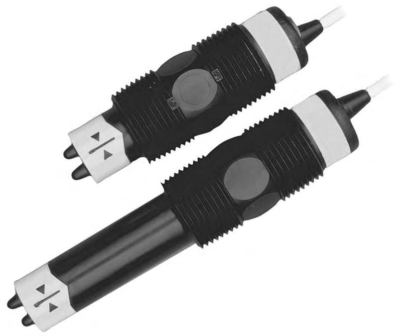
3 INTRODUCTION / TABLE OF CONTENTS Step One Offered in liquid and gas sensor types, the general purpose flow switch provides reliable low or no flow detection of relatively clean, non coating media with one 1A relay output. Liquid examples in clued water and acetic acid. Available in Polypropylene PPS or PVDF, the short flow sensor is used in pipe or ducting from ½ to 1 1/2, and the long flow sensor is used in 2 and up. The flow switch set point may be adjusted from 0.,04 to 3 fps in liquids or 1 to 90 fps in gases as a low flow alarm. The flow sensor is best applied in applications with relatively constant temperatures. New Features Rugged Polypropylene PPS or PVDF sensor for corrosive liquids and gasses. Adjustable set point with LED for flow or no flow status indication. 60VA relay selectable NO or NC via power supply wiring polarity Solid State sensor is not damaged by over ranging flow velocities. Table of Contents Specifications:... 4 Make a Fail Safe System:... 4 Dimensions:... 5 Configurations:... 5 Safety Precautions:... 6 Introduction:... 7 Technology:... 7 Initializing Sequence for FST 200 Series:... 7 Set Points:... 7 Installation:... 8 Wiring:... 9 Supply Voltage:... 9 Signal Output:... 9 Wiring to an Omega Engineering Controller:... 9 Wiring the Relay Output: Wiring as a P Channel or N Channel Output: Calibration: Set Point: Maintenance: Cleaning Procedure: Testing the Sensor (FST 200 Series Only): Testing the Sensor (FST 300 Series Only):

 @ 25 C., derated @ 1.667 psi (.")
 Cable length: 10 (3m) Process mount: 3/4\" NPT (3/4 G/Rp) Mount.")
4 SPECIFICATIONS Step Two Set point range: FST 200:.04 to 3 fps (.012 to.91 mps) FST 300: 1 to.90 fps (.3 to 27 mps) Factory set point: FST 200:.2 fps (.06 mps) FST 300: 10 fps (3 mps) Repeatability: ±.5% of set fixed temp. Response time: 1 10 seconds Set point adjust.: Potentiometer LED indication: Flow Status Viscosity range: centipoise (FST 200 series only) Supply Voltage: VDC Consumption: 70 ma maximum Contact type: (1) SPST relay Contact rating: 60 VA, 1A max Contact output: Selectable NO/NC Process temp.: F:32 to 140 C: 0 to 60 Electronics temp. F: 40 to 140 C: 40 to 60 Pressure: 150 psi (10 25 C., psi (.113 bar) per C. Above 25 C. Sensor rating: NEMA 4X (IP65) Sensor Material: FST 211/ 221/ 321/ 323: PP PPS FST 212/ 222/ 322/ 324: PVDF Cable jacket mat.: FST 211/ 221/ 321/ 323: PP FST 212/ 222/ 322/ 324: PFA Cable type: 4 conductor, #22 AWG (shielded) Cable length: 10 (3m) Process mount: 3/4" NPT (3/4 G/Rp) Mount. Gasket: FKM (G version only) Classification: General purpose CE compliance: EN EMC EN safety Make a Fail Safe System: Design a fail safe system that accommodates the possibility of switch and/or power failure. OMEGA ENGINEERING recommends the use of redundant backup systems and alarms in addition to the primary system. Adding a redundant alarm switch to the system is a cost effective means to prevent costly run dry issues. 4
 FST 211 SPST Short (3 ) PP PPS Polypropylene ¾ NPT x ¾ NPT FST 212 SPST Short (3 ) PVDF PFA ¾ NPT x ¾ NPT FST 221 SPST Long (4.")
 PVDF PFA ¾ NPT x ¾ NPT Configurations (Gas Flow Switches): Part Material Material Thread Length Number (body) (cable) (inside x outside) FST 321 SPST Short (3 ) PP PPS Polypropylene ¾ NPT x ¾ NPT")
5 DIMENSIONS Step Three Long Sensor (FST 221/ 222/ 323/ 324) Short Sensor (FST 211/ 212/ 321/ 322) Configurations (Liquid Flow Switches): Part Material Material Thread Length Number (body) (cable) (inside x outside) FST 211 SPST Short (3 ) PP PPS Polypropylene ¾ NPT x ¾ NPT FST 212 SPST Short (3 ) PVDF PFA ¾ NPT x ¾ NPT FST 221 SPST Long (4.5 ) PP PPS Polypropylene ¾ NPT x ¾ NPT FST 222 SPST Long (4.5 ) PVDF PFA ¾ NPT x ¾ NPT Configurations (Gas Flow Switches): Part Material Material Thread Length Number (body) (cable) (inside x outside) FST 321 SPST Short (3 ) PP PPS Polypropylene ¾ NPT x ¾ NPT FST 322 SPST Short (3 ) PVDF PFA ¾ NPT x ¾ NPT FST 323 SPST Long (4.5 ) PP PPS Polypropylene ¾ NPT x ¾ NPT FST 324 SPST Long (4.5 ) PVDF PFA ¾ NPT x ¾ NPT Note: The above products ship with a standard 10 cable length. Adding 25 to the end of the part number indicates that the product has a 25 cable length (ex. FST 211 SPST 25). Adding 50 to the end of the part number indicates that the product has a 50 cable length (ex. FST 321 SPST 50). 5


6 SAFETY PRECAUTIONS Step Four About this Manual: PLEASE READ THE ENTIRE MANUAL PRIOR TO INSTALLING OR USING THIS PRODUCT. This manual includes information on all models of Omega Engineering Thermal Dispersion Flow Switches: FST 200 and FST 300 series. Please refer to the part number located on the switch label to verify the exact model which you have purchased. User s Responsibility for safety: Omega Engineering manufactures a wide range of flow switches and technologies, while each of these sensors is designed to operate in a wide variety of applications; it is the user s responsibility to select a sensor model that is appropriate for the application, install it properly, perform tests of the installed system, and maintain all components. The failure to do so could result in property damage or serious injury. Proper Installation and Handling: Because this is an eclectically operated device, only properly trained staff should install and/or repair this product. Use a proper sealant with all installations. Note: Always install the 3/4 FKM gasket with all versions of Flow switches with metric threads. The G threaded version will not seal unless the gasket is properly installed. Never over tighten the sensor within the fitting, beyond a maximum of 80 inch pounds torque. Always check for leaks prior to system start up. Material Compatibility: The FST 200 and FST 300 series sensors are available in two different wetted materials. Models FST 211/ 221/ 321/ 323 are made of Polypropylene (PP) with PPS tips. Models FST 212/ 222/ 322/ 324 are made of Polyvinylidene Fluoride (PVDF). Make sure that the model you have selected is compatible with the application liquid. To determine the chemical compatibility between the sensor and its application liquids, refer to an industry reference such as the Compass Corrosion. Wiring and Electrical: The supply voltage used to power the sensor should never exceed a maximum of 36 volts DC. Electrical wiring of the sensor should be performed in accordance with all applicable national, state, and local codes. Flammable, Explosive and Hazardous Applications: DO NOT USE THE FST 200 or FST 300 SERIES GENERAL PURPOSE FLOW SWITCHES IN HAZAROUS LOCATIONS. The rating for the relay is 60 VA, 1Amp max. Warning Omega Engineering s Thermal Dispersion flow switches are not recommendable for use with electrically charged application liquids. For most reliable operation, the liquid being measured may need to be electrically grounded. The sensing tip of the sensor must always be submersed in the liquid and never exposed to air. The liquid temperature must remain constant and not change throughout the process. 6


7 INTRODUCTION Step Five Technology: The Thermal Dispersion flow switches measure liquid or gas temperature to determine changes in flow velocity. As fluid flows across the sensing tips, the temperature is reduced proportionately as a function of the flow rate. When a temperature or velocity shift reaches the user defined set point, the switch changes state indicating the appropriate flow condition (flow of no flow). OMEGA ENGINEERING s sophisticated electronics convert the temperature shift into a signal which indicates whether a flow or no flow condition occurs. Depending on how the sensor is wired, this signal may be wired for normally open or normally closed circuits. OMEGA ENGINEERING s Thermal Dispersion flow switches have no moving parts to clog or foul, making them suitable for a verity of applications, including non coating and non scaling liquids. The FST 200 series directly measure mass flow and can operate over board range of liquids from 0.4 to 1.2 specific gravity and 1 to 300 cp. Initializing Sequence for FST 200 series: When the flow switch is powered up while submersed, the FST 200 series will immediately indicate flow before switching to its correct state. A time delay may be used to eliminate the initialization sequence. Omega Engineering s thermal dispersion relay controllers feature a 0 to 60 second time delay for your convenience. Set Points: The FST 200 series liquid flow switch set point is factory calibrated to 0.2 fps and the FST 300 gas flow switch are set to 10 fps. To convert feet/sec to GPM, please refer to the chart below. FST 200 Series Flow Rate vs. Velocity (gpm vs. fps) FST 300 Series Flow Rate vs. Velocity (scfm vs. fps) 7

8 Installation Step Six The FST 200 series flow switch must always be in contact with the liquid being measured. The FST 300 series flow switch must never be submersed in liquid. Both flow switches feature a 3/4 NPT threads which will allow it to be used with various types of fittings. Be sure to check the insertion depth of the flow switch in the fitting after it is installed. See the diagram to the right for the recommended insertion depth. The two tip of the sensor are to be perpendicular to the flow (as seen to the right). Never mount the tips with one in from t of the other. When using any type of fitting, the orientation as well as the insertion depth of the flow switch in the pipe is critical. See the diagram to the right for the recommended orientation. Warning The flow switch tips have a thin plastic wall which may be damaged if dropped or installed improperly. The FST 200 series flow switch is designed for use in liquid. For best results, avoid installing the FST 200 series where bubbles are present or where the tips of the switch may be out of the liquid. The FST 300 series flow switch is designed for us in gas applications. For best results, avoid installing the FST 300 series where it may be submersed in liquid. Always install the FKM gasket with all versions of the model FST 212/ 222/ 322/ 324. The G threaded version will not seal unless the gasket is properly installed. The two temperature probes (tips) must always be perpendicular to the flow (see the flow at the same time). 8


9 WIRING Step Seven Supply Voltage: The supply voltage to the Thermal Dispersion flow switch should never exceed a minimum output of 14 VDC or maximum output of 36 VDC. Required Cable Length: Determine the length of the cable required between the Thermal Dispersion flow switch and its point of termination. Allow enough slack to ensure the easy installation, removal and/or maintenance of the sensor. The cable length may be extended up to a maximum of 1000 ft, using a wellinsulated 14 to 20 gauge shielded four conductor cable. Wire Stripping: Using a 10 gauge wire stripper, carefully remove the outer layer of insulation from the last 1 1/4 of the sensor s cable. Unwrap and discard the exposed foil shield from around the signal wires, leaving the drain wire attached if desired. With a 20 gauge wire stripper, remove the last 1/4 of the colored insulation from the signal wires. Signal Output (Relay Switching): Allows the sensor to switch a small load on or off directly, using an internal relay rated below 60 VA. The NO/NC status is set by the polarity of the voltage feeding the red and black wires. The green wire is the common for the relay and the white wire is the NO or NC, depending on the polarity of red and black. Normally Open Wiring: Wiring to an Omega Engineering Controller: LVCN 131/ 141 Series Controller FLCN 100 Series Controller 9

 VDC power or White to ( ) VDC power (see illustration to the right).")
10 WIRING Step Seven Wiring the Relay Output: The Flow switch relay output can be wired as a dry contact to a VDC or VAC power source. The flow switch does require VDC power to operate the sensor and switch the relay. All installations below identify a dry switch state as the normal position of the relay. Switching a Normally Open DC Load (Open during Flow, Closed during No Flow): The Red wire connects to Positive (+) of the power supply and the Black wire connects to Negative ( ). The LOAD can be attached to either the Green or White wires. Complete the circuit by connecting the Green to (+) VDC power or White to ( ) VDC power (see illustration to the right). Switching a Normally Closed DC Load (Closed during Flow, Open during No Flow): The Black wire connects to positive (+) of the power supply and the Red wire connects to Negative ( ). The Load can be attached to either the Green or White wires. Complete the circuit by connecting the Green to (+) VDC power or White to ( ) VDC power (see illustration to the right). Switching a Normally Open AC Load (Open during Flow, Closed during No Flow): The Red wire connects to Positive (+) of the DC power supply and the Black wire connects to Negative ( ). The LOAD can be attached to the Green wire and the Hot of the VAC power. Connect the white to the Neutral of the VAC power (see illustration to the right). Low voltage VAC is less than 36 VAC. Switching a Normally Closed AC Load (Closed during Flow, Open during No Flow): The Black wire connects to Positive (+) of the DC power supply and the Red wire connects to Negative ( ). The LOAD can be attached to the Green wire and the Hot of the VAC power. Connect the White to the Neutral of the VAC power (see illustration to the right). Low voltage VAC is less than 36 VAC. For all Sensor Wiring diagrams above: Sensor Power: Red and Black Wires (36 VDC Max.) Relay Rating: Green and White Wires (60VA, 1A Max.) 10
11 WIRING Step Seven Wiring as a P Channel or N Channel output: The Flow switch can be substituted for either a P Channel (PNP, Sourcing) output or N Channel (NPN, sinking) output. Normally Open DC Load as a P Channel Output (Open during Flow, Closed during No Flow): To wire as a NO P Channel output follow the directions below. The Red Wire connects to Positive (+) of the power supply and the Black wire connects to Negative ( ). The Green wire is jumping to the Red wire while the White wire is connected to the LOAD. Jumper the LOAD back to the Negative ( ) to complete the circuit. Normally Closed DC Load as a P Channel Output (Closed during Flow, Open during No Flow): To wire as a NC P Channel output, follow the directions below. The Black wire connects to Positive (+) of the power supply and the Red wire connects to Negative ( ). The Green wire is jumping to the Black wire while the White wire is connected to the LOAD. Jumper the LOAD back to the Negative ( ) to complete the circuit. Normally Open DC Load as a N Channel Output (Open during Flow, Closed during No Flow): To wire as a NO N Channel output, follow the directions below. The Red wire connects to Positive (+) of the power supply and the Black wire connects to Negative ( ). The white wire is jumping to the Black wire while the Green wire is connected to the LOAD. Jumper the LOAD back to the Positive (+) to complete the circuit. Normally Closed DC Load as a N Channel Output (Closed during Flow, Open during No Flow): To wire as a NC N Channel output, follow the directions below. The Black wire connects to Positive (+) of the directions below. The Black Wire connects to Negative ( ). The white wire is jumping to the Red wire while the White wire is connected to the LOAD. Jumper the LOAD back to Positive (+) to complete the circuit. For all Sensor Wiring diagrams above: Sensor Power: Red and Black Wires (36 VDC Max.) Relay Rating: Green and White Wires (60VA, 1A Max.) 11


12 CALIBRATION Step Eight Set Point: If the preset factory calibration is not adequate for your application, follow the calibration steps listed below. Note: The switch s internal LED will be on when the switch detects no flow and will off when the switch detects flow, regardless of the polarity of the Red and Black wires. Reversing the Red and Black wires will reverse the polarity of the relay switch, but not the internal LED. 1. Install the fitting and flow switch as described in the Installation section of this manual. Turn the flow switch and controller power on and adjust the flow rate to the application setting. If the medium to be sensed is likely to be subject to any temperature variation, the flow switch should be set as the highest normal temperature likely to be encountered. 2. Locate the potentiometer knob at the top of the flow switch. The red LED is visible through the potentiometer. The adjustment is a single turn 270 potentiometer. The initial response time of the flow switch after adjustment is 1 to 10 seconds. Adjust the potentiometer in slow increments and wait for the response. a. LED is ON If the LED is on, slowly adjust the potentiometer counter clockwise, with a small flat head screwdriver until the LED turn off. b. LED is OFF If the LED is off, slowly adjust the potentiometer clockwise. with a small flat head screwdriver until the light turns on. 3. Adjust the potentiometer back and forth where the LED is switching, eventually settling for where the LED is OFF (this is the low flow state for the switch). a. If the flow is increased, the LED will remain OFF indicating a flow condition b. If the flow is decrease, the LED will turn ON indicating a no flow condition. 4. Verify that the new calibration is correct by lowering the system flow rate below the set point and check to see that the red LED turns on. Then increase the flow rate above the set point and verify that the red LED turns off accordingly. FST 200 Series Flow Switch (Liquid Only) Potentiometer Location FST 300 Flow Switch (Gas Only) 12
13 MAINTENANCE Step Nine General: The Flow switch requires no periodic maintenance except to clean off any deposits or scaling from the sensor tip as necessary. It is the responsibility of the user to determine the appropriate maintenance schedule, based on the specific characteristics of the application liquids. Cleaning Procedure: 1. Power: Make sure that all power to the sensor, controller and/or power supply is completely disconnected. 2. Sensor Removal: Make sure that the flow is off and the pressure is down prior to removing the Flow switch. Carefully, remove the sensor from the installation. Replace the sensor with a 3/4 NPT plug to insure that the liquid does not leak out during this procedure. Do not re install the Flow switch if the threads are damaged. 3. Cleaning the sensor: Use a soft bristle brush and mild detergent, carefully wash the Thermal Dispersion flow switch. Do not use harsh abrasives such as steel wool or sandpaper, which might damage the surface sensor. Do not use incompatible solvents which may damage the surface sensor. Do not use incompatible solvents which may damage the sensor s PP/Ryton or PVDF plastic body. 4. Sensor Installation: Follow the appropriate steps of installation as outlined in the installation section of this manual. Testing the Sensor (FST 200 Series Only): 1. Immersing the switch: Place the switch in a cup of water. Make sure the tips are submersed in the water. 2. Power: Turn on power to the switch with Red to (+) and Black to ( ). You can reverse the polarity if desired. 3. No Flow/Flow Test: With the switch setting still in the cup, wait until the Red LED turns ON (no flow condition). a. Swirl the switch in the cup and wait until the Red LED turn OFF (flow condition). b. Stop swirling the sensor and let it rest in the cup waiting for the Red LED to turn ON again (no flow condition). c. Repeat the above two steps. 4. Relay Test: Connect a multimeter (set to read Ohms) to the White and Green Wires. Perform the above No Flow/Flow test with the multimeter connect to observe the actuation of the relay. a. With Red to (+) and Black to ( ), the multimeter will read a small resistance during no flow (closed relay) and OL during a flow condition (open relay). b. Reverse Polarity [Red to ( ) and Black to (+)] to see the multimeter read OL during a no flow state (open relay) and a small resistance during a flow condition (closed relay). The No Flow/Flow test determines if the switch is capable of sensing the changes between no flow and flow. The Relay test determines the ability of the relay to switch between a no flow and flow condition. This is the basic test to determine functionality of the sensor. 13
14 MAINTENANCE Step Nine Testing the Sensor (FST 300 Series Only): 1. Creating a No Flow Test Point: The purpose of this step is to create a no flow state for the sensor to be tested against. Since this is a low flow switch, even a buildings HVAC system can create a flow that the sensor can read. a. Place the switch on a table and place an empty cup over the sensing tips. b. The cup will act like a shield to protect the sensor from air flow. 2. Power: Turn on power to the switch with Red to (+) and Black to ( ). You can reverse the polarity if desired. 3. No Flow/Flow Test: With the switch setting still under the cup, wait until the Red LED turns ON (no flow condition). a. Remove the cup and move the sensor in air and observe when the Red LED turn OFF (flow condition). b. Place the sensor on the table and place the cup over the sensor and let it rest waiting for the Red LED to turn ON again (no flow condition). c. Repeat the above two steps. 4. Relay Test: Connect a multimeter (set to read Ohms) to the White and Green Wires. Perform the above No Flow/Flow test with the multimeter connect to observe the actuation of the relay. a. With Red to (+) and Black to ( ), the multimeter will read a small resistance during no flow (closed relay) and OL during a flow condition (open relay). b. Reverse Polarity [Red to ( ) and Black to (+)] to see the multimeter read OL during a no flow state (open relay) and a small resistance during a flow condition (closed relay). The No Flow/Flow test determines if the switch is capable of sensing the changes between no flow and flow. The Relay test determines the ability of the relay to switch between a no flow and flow condition. This is the basic test to determine functionality of the sensor. 14

15 15


16 16
Thermo-Flo Flow Switches FT10 and GT10 Series Owner s Manual
 Warranty, Service & Repair To register your product with the manufacturer, go to the Flowline website for on-line registration. The website address is as follows: www.flowline.com On-line Warranty Registration
Thermo Flo With Compact Junction Box AT17, AT18, AG17 & AG18 Series Manual
 Thermo Flo With Compact Junction Box AT17, AT18, AG17 & AG18 Series Manual Flowline Inc. 10500 Humbolt Street Los Alamitos, CA 90720 Tel: (562) 598 3015 Fax: (562) 431 8507 www.flowline.com Rev A MN301480
Introduction to Flow Switch
 Introduction to TM Solutions Flow Detection, Switching & Control Flow switches detect a change in state from flow or no-flow within pipe or ducting. Correspondingly, the sensor inverts a contact to signal
Switch-Pro. AU13 & AZ13 Series Owner s Manual. w/ Compact Relay Controller
 Switch-Pro w/ Compact Relay Controller AU13 & AZ13 Series Owner s Manual Flowline, Inc.. 10500 Humbolt Street, Los Alamitos, CA 90720. p 562.598.3015. f 562.431.8507. w flowline.com MN301450 Rev A Introduction
INTRODUCTION / TABLE OF CONTENTS
 1 2 INTRODUCTION / TABLE OF CONTENTS Step One The LVCN 20 and LVCN 100 Series are general purpose level controllers offered in two configurations for pump and valve control. The LVCN 100 Series features
INTRODUCTION / TABLE OF CONTENTS
 1 2 INTRODUCTI / TABLE OF CTENTS Step One The LVCN 51 Series Continuous Relay Controller is a general purpose level controller which provides single tank level indication with dual relays and a repeater
AV17 Series Switch-Tek Manual Direct and Remote Drum Mount Float Alarm 17 SEPT 08 Rev A
 AV17 Series Switch-Tek Manual Direct and Remote Drum Mount Float Alarm 17 SEPT 08 Flowline, Inc. 10500 Humbolt Street Los Alamitos, CA 90720 Tel: (562) 598-3015 Fax: (562) 431-8507 www.flowline.com 17
Introduction to Level Switch Solutions
 Introduction to Solutions TM Level Detection, Switching & Control Level switches detect a change in state from dry or wet at specific points within the tank and correspondingly invert contacts to signal
Page. 1-2 Sepra-Lite Integral Optic Level Switches. 3-5 Electro Optic Level Systems: Probe and Controller
 Order from: C A Briggs Company 622 Mary Street; Suite 101; Warminster, PA 18974 Phone: 267-673-8117-800-352-6265; Fax: 267-673-8118 Sales@cabriggs.com - www.cabriggs.com Page 1-2 Sepra-Lite Integral Optic
! WARNING. Before using product, read and understand instructions.
 Installation & Maintenance Instructions MM-616 Series FS-5 General Purpose Liquid Flow Switch specified models only) Series FS-5 OPERATION This control is an independently mounted water flow sensing device
INSTRUCTION MANUAL MM-615E. Series FS1 High Sensitivity Liquid Flow Switch
 INSTRUCTION MANUAL MM-615E 246717 Series FS1 High Sensitivity Liquid Flow Switch SPECIFICATIONS Maximum Liquid Pressure: 100 psi 7 kg/cm 2 ) Liquid Temperature Range TL): 32-225 F 0-107 C) Ambient Temperature
INSTALLATION INSTRUCTIONS FOR MOUNTING KIT
 RV Products Division INSTALLATION INSTRUCTIONS FOR 8330-5501 MOUNTING KIT 8330-752 CONTROL BOX KIT (12 VDC COOL ONLY) 9330B755 CONTROL BOX KIT (12 VDC HEAT/COOL) 8530-750 CONTROL BOX KIT (24 VAC COOL ONLY)
The sealless FLUX F 424
 The sealless FLUX F The liquids to be pumped are abrasive, but they do not leave any deposits. Dry running of the pump must not cause any problems. You are looking for a lightweight, general purpose pump
INSTALLATION, OPERATING & MAINTENANCE INSTRUCTIONS FOR 350 SERIES CIRCULATION HEATERS
 INDEECO Circulation Heaters are designed to provide years of trouble free operation if properly installed and maintained. Please read and follow these instructions for installing and maintaining the heater.
INSTALLATION INSTRUCTIONS FOR 8330*5511 MOUNTING KIT
 RV Products Division INSTALLATION INSTRUCTIONS FOR 8330*5511 MOUNTING KIT 8330-752 CONTROL BOX KIT (12 VDC COOL ONLY) 9330A755 CONTROL BOX KIT (12 VDC HEAT/COOL) 8530-750 CONTROL BOX KIT (24 VAC COOL ONLY)
INSTALLATION INSTRUCTIONS FOR 9330F4552 FREE DELIVERY PLENUM KITS
 RV Products Division INSTALLATION INSTRUCTIONS FOR 9330F4552 FREE DELIVERY PLENUM KITS 8330-752 CONTROL BOX KIT (12 VDC COOL ONLY) 9330C755 CONTROL BOX KIT (12 VDC HEAT READY) 8530-750 CONTROL BOX KIT
INSTALLATION INSTRUCTIONS FOR 7330*5511 OR 7330*5512 MOUNTING KIT 7330B751 CONTROL BOX KIT (12 VDC COOL ONLY)
") INSTALLATION INSTRUCTIONS FOR 7330*5511 OR 7330*5512 MOUNTING KIT 7330B751 CONTROL BOX KIT (12 VDC COOL ONLY) 7530B750 CONTROL BOX KIT (24 VAC COOL ONLY) 8330A751 ZONE CONTROL KIT (12 VDC COOL ONLY) 8530B751
INSTALLATION INSTRUCTIONS FOR 7330*5511 OR 7330*5512 MOUNTING KIT 7330B751 CONTROL BOX KIT (12 VDC COOL ONLY) 7530B750 CONTROL BOX KIT (24 VAC COOL ONLY) 8330A751 ZONE CONTROL KIT (12 VDC COOL ONLY) 8530B751
Sidel Combi-Combi Therm & CO2 Counter Installation Guide
 Sidel Combi-Combi Therm & CO2 Counter Installation Guide Introduction Thank you for purchasing the Sidel Combi-Combi Therm & CO 2 Counter. The Combi-Combi Therm & CO 2 Counter control panel should be installed
Intrinsically Safe Pressure Transmitters for installation in hazardous locations Models IS-20-S, IS-21-S, IS-20-F, IS-21-F WIKA Datasheet IS-20
 Electronic Pressure Measurement Intrinsically Safe Pressure Transmitters for installation in hazardous locations Models IS-20-S, IS-21-S, IS-20-F, IS-21-F WIKA Datasheet IS-20 Applications Chemical, Petrochemical
OilSET-1000 (12 VDC)
") Labkotec Oy Myllyhaantie 6 FI-33960 PIRKKALA FINLAND Tel: +358 29 006 260 Fax: +358 29 006 1260 Internet: www.labkotec.fi 20.03.2009 1/11 OilSET-1000 (12 VDC) Oil Separator Alarm Device Copyright 2009
Labkotec Oy Myllyhaantie 6 FI-33960 PIRKKALA FINLAND Tel: +358 29 006 260 Fax: +358 29 006 1260 Internet: www.labkotec.fi 20.03.2009 1/11 OilSET-1000 (12 VDC) Oil Separator Alarm Device Copyright 2009
PodView Level Indicator LI40 Series Manual
 PodView Level Indicator LI40 Series Manual Flowline Inc. 10500 Humbolt Street Los Alamitos, CA 90720 Tel: (562) 598 3015 Fax: (562) 431 8507 www.flowline.com Rev A MN204260 1 of 16 INTRODUCTION / TABLE
Model Gas Alarm Panel APPLICABILITY & EFFECTIVITY. This manual provides instructions for the following Sierra Monitor products:
 Model 2102 Gas Alarm Panel APPLICABILITY & EFFECTIVITY This manual provides instructions for the following Sierra Monitor products: Model Description 2102-00 Alarm Panel 2 Channel 2102-01 Alarm Panel 2
SP-1000X. Panic Device Power Controller Installation Guide. Rev
 TM SP-1000X Panic Device Power Controller Installation Guide Rev. 120213 Overview: SP-1000X will operate up to two (2) 24VDC panic hardware devices simultaneously. It is designed to handle the high current
SET-2000 Oil/Sludge. Alarm Device for Oil Separators. Installation and Operating Instructions
 SET-000 Oil/Sludge Alarm Device for Oil Separators Copyright 007 Labkotec Oy We reserve the right for changes without notice TABLE OF CONTENTS GENERAL... INSTALLATION... 4. SET-000 Oil/Sludge Control Unit...
NT1-P CONDENSATE NEUTRALIZATION TANK WITH PUMP INSTALLATION, OPERATION, AND MAINTENANCE INSTRUCTIONS
 NT1-P CONDENSATE NEUTRALIZATION TANK WITH PUMP INSTALLATION, OPERATION, AND MAINTENANCE INSTRUCTIONS NOTE - Check with your local water authority for regulations regarding discharge of treated condensate
! WARNING. Before using product, read and understand instructions.
 McDonnell & Miller Installation & Maintenance Instructions MM-607(B) Series FS7-4 Industrial Liquid Flow Switch (specified models only) Series FS7-4 OPERATION This control is an independently mounted water
OPTISENS TUR 2000 Technical Datasheet
 OPTISENS TUR 2000 Technical Datasheet Sensor for turbidity measurement in water and wastewater Rugged design for harsh applications Integrated transmitter with direct 4...20 ma output Near infrared light
SET-2000 Oil/Sludge 12 VDC
 Labkotec Oy Myllyhaantie 6 FI-33960 PIRKKALA FINLAND Tel: + 358 29 006 260 Fax: + 358 29 006 1260 12.2.2015 Internet: www.labkotec.fi 1/14 SET-2000 Oil/Sludge 12 VDC Alarm Device for Oil Separators with
! WARNING. Before using product, read and understand instructions.
 Installation & Maintenance Instructions MM-60C) Series FS4-3 General Purpose Liquid Flow Switch specified models only) Now with Stainless Steel Paddles OPERATION This control is an independently mounted
MAINTENANCE & TROUBLESHOOTING GUIDE LEAK ALARM CHANNEL DRY OIL WATER AUX ALARM HIGH LOW CRITICAL WATER TANK LEVEL ALARM MODEL LDE-740 ADVANCE PAPER
 PNEUMERCATOR Liquid Level Control Systems Electronic Systems Excluding LC2000 And TMS Series MAINTENANCE & TROUBLESHOOTING GUIDE 400 300 500 FUEL LEVEL LEAK MONITOR 1 200 600 OIL/GAS NORMAL WATER PNEUMERCATOR
INSTALLATION INSTRUCTIONS FOR MOUNTING KIT 7330B751 CONTROL BOX KIT (12 VDC COOL ONLY) CONTROL BOX KIT (12 VDC HEAT/COOL)
 CONTROL BOX KIT (12 VDC HEAT/COOL)") INSTALLATION INSTRUCTIONS FOR 8330-5511 MOUNTING KIT 7330B751 CONTROL BOX KIT (12 VDC COOL ONLY) 9330-755 CONTROL BOX KIT (12 VDC HEAT/COOL) 7530B750 CONTROL BOX KIT (24 VAC COOL ONLY) 9530-755 CONTROL
INSTALLATION INSTRUCTIONS FOR 8330-5511 MOUNTING KIT 7330B751 CONTROL BOX KIT (12 VDC COOL ONLY) 9330-755 CONTROL BOX KIT (12 VDC HEAT/COOL) 7530B750 CONTROL BOX KIT (24 VAC COOL ONLY) 9530-755 CONTROL
SET-2000 Hi Level/Oil
 Labkotec Oy Labkotie 1 FI-36240 KANGASALA FINLAND Tel: + 358 29 006 260 Fax: + 358 29 006 1260 13.03.2008 Internet: www.labkotec.fi Alarm Device for Oil Separators Copyright 2008 Labkotec Oy We reserve
SERVICE MANUAL. Bradford White ElectriFLEX HD (Heavy Duty) Commercial Electric Water Heater CEHD SERIES Immersion Thermostat Models
 Commercial Electric Water Heater CEHD SERIES Immersion Thermostat Models") Bradford White ElectriFLEX HD (Heavy Duty) Commercial Electric Water Heater CEHD SERIES Immersion Thermostat Models SERVICE MANUAL Troubleshooting Guide and Instructions for Service (To be performed ONLY
Bradford White ElectriFLEX HD (Heavy Duty) Commercial Electric Water Heater CEHD SERIES Immersion Thermostat Models SERVICE MANUAL Troubleshooting Guide and Instructions for Service (To be performed ONLY
DataPoint Continuous Relay Controller LC52 Series Manual
 DataPoint Continuous Relay Controller LC52 Series Manual Flowline Inc. 10500 Humbolt Street Los Alamitos, CA 90720 Tel: (562) 598 3015 Fax: (562) 431 8507 www.flowline.com Rev A2 LC900007 1 of 18 INTRODUCTION
RK-05 Combustible Gas Transmitter Operator s Manual
 65-2405RK-05 Combustible Gas Transmitter Operator s Manual Part Number: 71-0180RK Revision: 0 Released: 2/16/11 RKI Instruments, Inc. www.rkiinstruments.com WARNING Read and understand this instruction
Continuous Relay Controller LC52 Series Owner s Manual
 Warranty, Service & Repair To register your product with the manufacturer, fill out the enclosed warranty card and return it immediately to: Flowline Inc. 10500 Humbolt Street Los Alamitos, CA 90720. If
Power Supply Display Module PSDM. Installation and Operation Manual
 Power Supply Display Module PSDM Installation and Operation Manual Read this manual before using this product. Failure to follow the instructions and safety precautions in this manual can result in serious
OilSET Installation and Operating Instructions. Oil Separator Alarm Device
 Labkotec Oy Myllyhaantie 6 FI-33960 PIRKKALA FINLAND Tel: +358 29 006 260 Fax: +358 29 006 1260 18.11.2010 Internet: www.labkotec.fi 1/10 OilSET-1000 Oil Separator Alarm Device Copyright 2010 Labkotec
Tankless On Demand Electric Water Heater
 ECO FRIENDLY 98% EFFICIENT ENERGY & WATER SAVING Model MTX Tankless On Demand Electric Water Heater Available Up To 54 KW in Single or Three Phase Voltages Marine Approvals American Bureau of Shipping
TABLE OF CONTENTS Flow Detect 1000 Specifications 3 Description 4 Principle of Operation 4 Detection Through Walls 4 Sensing Beam Shape 4 Installation
 DETECT 1000 DOPPLER DETECTION INSTALLATION AND OPERATING INSTRUCTIONS READ THOROUGHLY BEFORE INSTALLING EQUIPMENT TABLE OF CONTENTS Flow Detect 1000 Specifications 3 Description 4 Principle of Operation
P6500W Air Dryer User s Guide
 P6500W Air Dryer User s Guide 1. Welcome & Congratulations Congratulations on your purchase of a new PUREGAS P6500W Air Dryer! We here at PUREGAS are very proud of our products and we are committed to
TABLE 1 Electrical Specifications
 CHRONOMITE HIGH CAPACITY INSTANT-TEMP WATER HEATERS INSTALLATION AND OPERATION INSTRUCTIONS (208-240V Models) (Before installation, compare electrical requirements needed for the model of heater selected)
Series. Access Power Controllers. Installation Guide
 Series Access Power Controllers Installation Guide Models Include: Maxim11 - Power Supply 1: 12VDC @ 3.5 amp or 24VDC @ 2.7 amp. - Power Supply 2: 12VDC @ 3.5 amp or 24VDC @ 2.7 amp. - Sixteen (16) fuse
OilSET Installation and Operating Instructions. Oil Separator Alarm Device with SET/DM3AL sensor
 Labkotec UK Ltd Adminicle House 1 Lumb Lane Audenshaw Manchester M34 5WH GREAT BRITAIN Tel: 0844 3350 477 Fax: 0161 4281 179 E-mail: info@labkotec.co.uk 10.8.2012 Internet: www.labkotec.co.uk 1/13 OilSET-1000
RK Hydrogen Sulfide Transmitter Operator s Manual
 65-2331RK Hydrogen Sulfide Transmitter Operator s Manual Part Number: 71-0176RK Revision: B Released: 11/26/14 RKI Instruments, Inc. www.rkiinstruments.com WARNING Read and understand this instruction
1040 Gas Monitor INSTALLATION AND OPERATING INSTRUCTIONS AMC-1040 WITH INTEGRAL ELECTROCHEMICAL SENSOR
 1040 Gas Monitor INSTALLATION AND OPERATING INSTRUCTIONS AMC-1040 WITH INTEGRAL ELECTROCHEMICAL SENSOR IMPORTANT: Please read these installation and operating instructions completely and carefully before
Duct and Rough Service Carbon Monoxide Sensor
 Product Identification and Overview Duct and Rough Service Carbon Monoxide Sensor BAPI s Carbon Monoxide Sensor offers enhanced electrochemical sensing with outstanding accuracy at low concentrations.
INSTALLATION, OPERATION INSTRUCTIONS FOR FLOW SWITCHES 62-9FS & FS
 THERMAL INSTRUMENT Co. 217 Sterner Mill Road, Trevose, PA 19053 Telephone No. (215) 355-8400 Fax No. (215) 355-1789 Email: office@thermalinstrument.com INSTALLATION, OPERATION INSTRUCTIONS FOR FLOW SWITCHES
Models Series Series
 Models 3180-Series 3181-Series INDUSTRIAL DIAPHRAGM PUMPS Commercial Duty, 3 GPM/1 LPM FEATURES Sealless Easy Installation Run Dry Ability Flow to 3 GPM/1 LPM Self-Priming Low Amp Draw Thermal Overload
Models Series Series
 Models 31800-Series 31801-Series INDUSTRIAL DIAPHRAGM PUMPS 4 GPM/15 LPM FEATURES Self-Priming Easy Installation Can run dry without damage Low Amp Draw Flow to 4 GPM/15 LPM Compact Size Thermal Overload
Wiring Instructions. High-Capacity Steam Humidifiers
 Wiring Instructions for High-Capacity Steam Humidifiers Including Instructions for Compensating Humidistat and Safety Control Shutoff CONTRACTOR: Read these instructions before installing or servicing
TABLE 1 Electrical Specifications. Phase
 CHRONOMITE HIGH CAPACITY INSTANT-TEMP WATER HEATERS INSTALLATION AND OPERATION INSTRUCTIONS (208-240V 3 Φ Models) (Before installation, compare electrical requirements needed for the model of heater selected)
Schneider Electric Erie T155 Series
 Schneider Electric Erie T Series Non-Digital, On/Off Thermostat General Instructions Application The T series thermostat provides on/off control for low voltage and line voltage valves, relays and fan
FLT93 Installation, Operation and Troubleshooting Guide
 FLT93 Installation, Operation and Troubleshooting Guide Pre-Installation A. To get the best results from the instrument, the instrument should be mounted 20 pipe diameters downstream from any valve, pipe
MODEL: O ELECTROCHEMICAL O2 DETECTOR (Used with ST1400 O2 Sensor) Part Number: MAN Rev. 0
 Part Number: MAN Rev. 0") MODEL: O2-25-24 ASSEMBLY CONSISTS OF: XP-O2 housing (supersedes PE-EX-O2) ST1400-500-24 sensor (supersedes PE1400-500-24) JB2 junction box CB2 connector board ELECTROCHEMICAL O2 DETECTOR (Used with ST1400
MODEL: O2-25-24 ASSEMBLY CONSISTS OF: XP-O2 housing (supersedes PE-EX-O2) ST1400-500-24 sensor (supersedes PE1400-500-24) JB2 junction box CB2 connector board ELECTROCHEMICAL O2 DETECTOR (Used with ST1400
Static Pressure Alarm For Hazardous Location Fume Hoods
 Static Pressure Alarm For Hazardous Location Fume Hoods Models: XPA1-0715 Class 1, Division 1, Group C, D 120V/15A/60Hz Pressure range 0.07 to 0.15 in-wg XPA1-1550 Class 1, Division 1, Group C, D 120V/15A/60Hz
PolyGard Single Point Controller SPC-X3-20XX for refrigerant gases and vapours
 PolyGard Single Point Controller SPC-X3-20XX for refrigerant gases and vapours DESCRIPTION Gas measuring, monitoring and warning controller based on state-of-the-art micro-technology with integrated sensor
Sitron s CF Line of Flow Switch Monitors
 Sitron s CF Line of Flow Switch Monitors Models: CF 12AC CF 12DC CF 420 F 420 RCF 420 Introduction Sitron s versatile and intelligent line of Thermal Dispersion Flow Switch Monitors are compact switches,
F PC and AO OUTPUT BOARDS INSTRUCTION MANUAL. Blue-White. Industries, Ltd.
 F-2000 PC and AO OUTPUT BOARDS INSTRUCTION MANUAL Blue-White R Industries, Ltd. 500 Business Drive Huntington Beach, CA 92649 USA Phone: 714-89-8529 FAX: 714-894-9492 E mail: sales@blue-white.com or techsupport@blue-white.com
Instruction Manual. Princo Model L3522. Point Level Controllers with LEVEL SENTRY. Rev 2, June 2013
 Instrumentation designed with the user in mind Instruction Manual Princo Model L3522 Point Level Controllers with LEVEL SENTRY Rev 2, June 2013 PRINCO INSTRUMENTS INC., 1020 INDUSTRIAL BLVD., SOUTHAMPTON,
Model 3300 Technical Support and Installation Manual
 Model 3300 Technical Support and Installation Manual Manual # T15011 Document Revision: A1 1. OVERVIEW 1 2. BASIC OPERATION 1 2.1 General 1 2.2 Field-of-View 2 2.3 Range 2 2.4 Environment 2 2.5 Configuration
RK Combustible Gas Transmitter Operator s Manual
 65-2400RK Combustible Gas Transmitter Operator s Manual Part Number: 71-0060RK Revision: C Released: 1/31/13 www.rkiinstruments.com WARNING Read and understand this instruction manual before operating
AMERITROL, INC. INSTALLATION OPERATION MANUAL AND WIRING DIAGRAM LX SERIES LIQUID LEVEL SWITCH WITH ADDITIONAL TEMPERATURE TRANSMITTER
 AMERITROL, INC. INSTALLATION OPERATION MANUAL AND WIRING DIAGRAM LX SERIES LIQUID LEVEL SWITCH WITH ADDITIONAL TEMPERATURE TRANSMITTER Manual Number: LXTT-SPDT-2114-1-A 1185L Park Center Dr. Vista CA 92081
Quick Start Manual July pointek CLS100
 Quick Start Manual July 2009 pointek CLS100 Safety Guidelines: Warning notices must be observed to ensure personal safety as well as that of others, and to protect the product and the connected equipment.
RK Transmitter Technical Notice
 65-2450RK Transmitter Technical Notice Although this Operator s Manual was written for the 65-2400RK combustible gas LEL transmitter, the operational instructions are the same for the 65-2450RK hydrogen
ADC150 Automatic Draft Control
 Installation & Operating Manual ADC150 Automatic Draft Control USA CAN Product Information... Chapters 1 + 2 Mechanical Installation... Chapter 3 Electrical Installation... Chapter 4 Start Up and Configuration...
PolyGard 2-channel Gas Controller MGC-03
 PolyGard 2-channel Gas Controller MGC-03 DESCRIPTION Gas measuring and monitoring controller based on state-ofthe-art micro-technology with integrated buzzer for continuous monitoring of the ambient air
INSTALLATION INSTRUCTIONS FOR 8330*633* COOL ONLY A/C 8330*635* HEAT READY A/C 8530*63** HEAT PUMP CHILLGRILLE FLUSH MOUNT CEILING ASSEMBLY
 RV Products Division INSTALLATION INSTRUCTIONS FOR 8330*633* COOL ONLY A/C 8330*635* HEAT READY A/C 8530*63** HEAT PUMP CHILLGRILLE FLUSH MOUNT CEILING ASSEMBLY DESIGNED AND MANUFACTURED BY THE MAKERS
Installation & Operating Guide
 5-036 HOT WATER TANK Installation & Operating Guide Read all instructions thoroughly. Keep this guide for future reference. Proof of purchase is required for Warranty. Staple receipt or proof of purchase
Operating Instructions. For. Alarm Control Module. Model SSR 500
 SSR 500 LEVEL CONTROL RELAY MODULE Operating Instructions For Alarm Control Module Model SSR 500 SSR Operation Instructions Rev. 1 Jan 01 Page 1/7 1. Note Please read and take note of these operating instructions
Tankless Electric Water Heater Available 3-27 kw in Single Phase Voltages
 Point-of-Use Tankless Tankless Electric Water Heater Available 3-27 kw in Single Phase Voltages Features Heavy Duty Construction Reliability Constructed with high grade materials to ensure long operating
STATION MODEL: KPCG21-24x48 PUMP MODEL: KEEN KPCG21 VOLTAGE: 230 PHASE: 1 TANK DIMENSIONS: 24 DIAMETER X 48 DEEP
 STATION MODEL: KPCG21-24x48 PUMP MODEL: KEEN KPCG21 VOLTAGE: 230 PHASE: 1 TANK DIMENSIONS: 24 DIAMETER X 48 DEEP PUMP Grinder Pumps KPCG-21 1HP Dual Seal, High Performance Progressive Cavity Grinder Pump,
AQUAS POOL PACKAGE INSTALLATION INSTRUCTIONS FOR MODELS: AP AQUAS Pool Package
 100285340_2000542910_Rev A AQUAS POOL PACKAGE INSTALLATION INSTRUCTIONS FOR MODELS: AP 400-850 AQUAS Pool Package The AQUAS pool package system is a high efficiency commercial condensing boiler, pre-piped
Installing the Cisco ONS FAP-4 Fuse Alarm Panel
 Installing the Cisco ONS 15454-FAP-4 Fuse Alarm Panel Product Number: 15454-FAP-4= This document explains how to install, test, operate, and maintain the Cisco ONS 15454-FAP-4 fuse alarm panel. This document
Technical Specification VFD
 Technical Specification - 3-6 VFD Pilot valve enclosures suitable for use in hazardous certified environments. These enclosures are designed and tested to contain both flame and the ignition of dust and
CP CP
 CP-8161-333 CP-8161-433 Electronic Programmable Controller Six Stage, Dual Setpoint General Instructions APPLICATION Electronic six stage programmable controller with proportional output for heating, cooling
Series 47 and 247 Mechanical Water Feeders. Series 47-2 and Combination Mechanical Water Feeder/Low Water Cut-Off ! WARNING
 Series 47 and 247 Mechanical Water Feeders McDonnell & Miller Installation & Maintenance Instructions MM-316(C) Series 47-2 and 247-2 Combination Mechanical Water Feeder/Low Water Cut-Off Series 47 Water
Centro-Matic Automated Lubrication Systems System Controls
 Selecting the right controls for your automated lubrication system is one of the last steps in the design process. Several different models may be chosen to control power-operated pumps, depending on the
PolyGard Single Point Controller SPC-X3-11XX for Toxic Gases and Oxygen
 PolyGard Single Point Controller SPC-X3-XX for Toxic Gases and Oxygen DESCRIPTION Gas measuring, monitoring and warning controller based on state-of-the-art micro-technology with integrated sensor and
Tox-COMB/ANA Combustible Gas Transmitter Operator s Manual
 Tox-COMB/ANA Combustible Gas Transmitter Operator s Manual Part Number: 71-0132TA Revision: A Released: 4/23/10 www.toxalert.com Product Warranty Toxalert International, Inc. warrants gas alarm equipment
VIBRATION TRANSMITTER MODEL 140T INSTALLATION The mounting orientation can be in any position. This position should be in an area for the best vibrati
 VIBRATION TRANSMITTER MODEL 140T A lowcost, yet highly accurate and rugged vibration transmitter, the Model 140T is ideal for use with all machines, even those which previously may have been considered
MODEL LP3 INSTALLATION AND SERVICE INSTRUCTIONS FOR STREAMLINE LP3 STROBE LIGHTS
 Specifications subject to change without notice. USA 150303 Page 1 of 10 MODEL LP3 INSTALLATION AND SERVICE INSTRUCTIONS FOR STREAMLINE LP3 STROBE LIGHTS Specifications subject to change without notice.
HOT WATER BOTTLE BATH PART NUMBER
 If you need any assistance or if you have questions about this item, call our Tech Help Line at (254) 848-4300. Do not use this product without filling it with water or immediate damage can result. All
LC2200 Level Controller Installation and Maintenance Instructions
 4025250/9 IM-P402-77 AB Issue 9 LC2200 Level Controller Installation and Maintenance Instructions LC2200 ALARM TEST >50% >100%
RK CO 2 Transmitter Operator s Manual
 65-2397RK CO 2 Transmitter Operator s Manual Part Number: 71-0185RK Revision: B Released: 7/18/14 RKI Instruments, Inc. www.rkiinstruments.com WARNING Read and understand this instruction manual before
FCHM Hydromatic Pump Control Module
 FCHM Hydromatic Pump Control Module Use To maintain and control water pressure, within a pumped system, for the supply to industrial processes and heating systems. Ensures constant flow and pressure to
Ultrasonic Point Level Switches
 see more at SORInc.com Request Quote Ultrasonic Point Level Switches Ultrasonic point level switches are a cost-effective solution for your applications. Installation requires mounting the sensor (threaded
Sensor Interface Module Installation/Operation Instructions
 TraceTek TTSIM-1 Sensor Interface Module Installation/Operation Instructions Approvals and Certifications TYPE NM General Signaling Equipment 76LJ Only AC versions are UL listed and VDE Certified. For
INSTALLATION INSTRUCTIONS FOR 8330*63**, 8530*63** CHILLGRILLE FLUSH MOUNT CEILING ASSEMBLY
 RV Products Division INSTALLATION INSTRUCTIONS FOR 8330*63**, 8530*63** CHILLGRILLE FLUSH MOUNT CEILING ASSEMBLY DESIGNED AND MANUFACTURED BY THE MAKERS OF COLEMAN -MACH AIR CONDITIONERS TABLE OF CONTENTS
C1N Series - Light Industrial Heaters Tankless Water Heating Solutions
 18-25 kw (61,4000-85,300 BTUs) Low flow activation options at 0.25 and 0.50 GPM (1.0 and 1.9 LPM) Certified Lead-Free Design Variable Temp Heat Exchanger Pressure Drop Advantage NEMA 4 enclosure standard
TRUERH Series HE-67xx Humidity Element with Temperature Sensor
 Installation Instructions HE-67xx Issue Date 0501 TRUERH Series HE-67xx Humidity Element with Temperature Sensor Installation IMPORTANT: The HE-67xx Series Humidity Element with Temperature Sensor is designed
MODEL A-316 CARBON MONOXIDE (CO) MONITOR AND ALARM FOR COMPRESSED AIR TESTING
 MONITOR AND ALARM FOR COMPRESSED AIR TESTING") MODEL A-316 CARBON MONOXIDE (CO) MONITOR AND ALARM FOR COMPRESSED AIR TESTING FOR OPERATION FROM 115 AC POWER Andersen Medical Gas 12 Place Lafitte Madisonville, LA 70447 http://www.themedicalgas.com 1-866-288-3783
MODEL A-316 CARBON MONOXIDE (CO) MONITOR AND ALARM FOR COMPRESSED AIR TESTING FOR OPERATION FROM 115 AC POWER Andersen Medical Gas 12 Place Lafitte Madisonville, LA 70447 http://www.themedicalgas.com 1-866-288-3783
vibration switch
 user manual 440-450 vibration switch INSTALLATION - OPERATION - MAINTENANCE Z0592822_A ISSUED 06/2017 READ AND UNDERSTAND THIS MANUAL PRIOR TO OPERATING OR SERVICING THIS PRODUCT. contents Section 1 -
CNA-Series - Large Industrial Heaters Tankless Water Heating Solutions
 36-144 kw (122,800-491,300 BTUs) Certified Lead-Free Design New & Improved Pressure Drop Advantage Variable Temp Heat Exchanger NEMA 4 enclosure standard Independent Safeties ETL and cetl certified to
INSTRUCTION MANUAL MM-601REVI. Series FS4-3 General Purpose Liquid Flow Switch
 INSTRUCTION MANUAL MM-601REVI 246796 Series FS4-3 General Purpose Liquid Flow Switch SPECIFICATIONS Maximum Liquid Pressure: 160 psi (11.3 kg/cm 2 ) Liquid Temperature Range (TL): 32-300 F (0-149 C) Ambient
Public Safety DAS Annunciator Panel
 Public Safety DAS Annunciator Panel 120 VAC Models: 1221-A, 1221-B, 1221-C Revision D 91117 48 VDC Models: 1221-A-48, 1221-B-48, 1221-C-48 24 VDC Models: 1221A-24, 1221-B-24, 1221-C-24 CAUTION: (Read This
10 to 30 VDC Diffuse 40 mm ±10 mm NPN and PNP, switch-selectable
 R Label Detection Sensor E3S-CD68/63 Detect Labels Regardless of Label Color or Luster, Bottle Color or Clarity H High-performance circuitry detects wide variety of labels on clear and colored bottles
Macurco HD-11 Hydrogen Gas Detector
 Macurco HD-11 Hydrogen Gas Detector User Instructions Important: Keep these User Instructions for reference TABLE OF CONTENTS GENERAL SAFETY INFORMATION 3 Intended Use 3 List of Warnings and Cautions 3
Modus Model DA General Eastern Low Differential Pressure Alarm Controller
 GE Sensing & Inspection Technologies Modus Model DA General Eastern Low Differential Alarm Controller The Modus Model DA is a controller designed for the monitoring of low differential pressures. It combines
Wallace & Tiernan Liquid Feed System LVN-2000 Liquid V-Notch
 Wallace & Tiernan Liquid Feed System LVN-2000 Liquid V-Notch Overview continues to be the leader in the chemical feed and disinfection of potable water, wastewater and industrial process applications.