NOZZLE MIX COMBINATION BURNER NMC200 SERIES
|
|
|
- Claribel Hood
- 5 years ago
- Views:
Transcription

1 NOZZLE MIX COMBINATION BURNER NMC200 SERIES INSTRUCTIONS WARNING These instructions are intended for use only by experienced, qualified combustion start-up personnel. Adjustment of this equipment and its components, by unqualified personnel, can result in fire, explosion, severe personal injury, or even death. Subject Page A. General Information B. Receiving and Inspection C. Capacities.. 3 D. Dimensions E. Typical Piping Schematics 9 F. Installation 10 G. Operation. 12 H. Maintenance 12 These instructions are intended to serve as guidelines covering the installation, operation, and maintenance of Hauck equipment. While every attempt has been made to ensure completeness, unforeseen or unspecified applications, details, and variations may preclude covering every possible contingency. WARNING: TO PREVENT THE POSSIBILITY OF SERIOUS BODILY INJURY, DO NOT USE OR OPERATE ANY EQUIPMENT OR COMPONENT WITH ANY PARTS REMOVED OR ANY PARTS NOT APPROVED BY THE MANUFACTURER. Should further information be required or desired or should particular problems arise which are not covered sufficiently for the purchaser s purpose, contact Hauck Mfg. Co. HAUCK MANUFACTURING CO., P.O. Box 90 Lebanon, PA /08 Fax:
2 Page 2 WARNING This equipment is potentially dangerous with the possibility of serious personal injury and property damage. Hauck Manufacturing Company recommends the use of flame supervisory equipment and fuel safety shutoff valves. Furthermore, Hauck urges rigid adherence to National Fire Protection Association (NFPA) standards and insurance underwriter s requirements. Operation and regular preventative maintenance of this equipment should be performed only by properly trained and qualified personnel. Annual review and upgrading of safety equipment is recommended. A. GENERAL INFORMATION The NMC Series Nozzle Mix Burner is designed for applications requiring a general purpose, long-life, low maintenance burner. The NMC performs equally well when firing "on ratio", with excess fuel, or with excess air. The NMC will burn any clean industrial gas, No. 2 oil, or a combination of gas and oil. These units will not operate on No.6 or a mixture of heavy oil and distillate oil. NMC burners can be controlled manually or automatically. Automatic control normally employs a Hauck Ratio Regulator for each control zone to maintain air-fuel ratio. An alternate system uses control valves in each of the fuel air lines, linking the valves to a single motor controller. B. RECEIVING AND INSPECTION Upon receipt, check each item on the bill of lading and/or invoice to determine that all equipment has been received. A careful examination of all parts should be made to ascertain if there has been any damage in shipment. IMPORTANT If the installation is delayed and the equipment is stored outside, provide adequate protection as dictated by climate and period of exposure. Special care should be given to all motors and bearings, if applicable, to protect them from rain or excessive moisture.
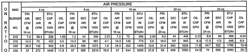
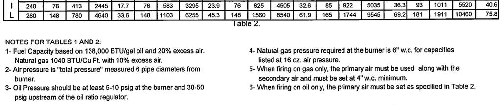
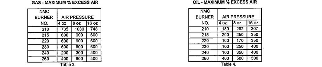
3 C. CAPACITIES Page 3


4 D. DIMENSIONS Page 4 Y2466 (NOT TO SCALE) Figure 1. Dimensions NMC 210 NMC 240

5 Page 5 Y2466 METRIC (NOT TO SCALE) Figure 2. Metric Dimensions NMC 210 NMC 240
6 Page 6 Y2467 (NOT TO SCALE) Figure 3. Dimensions NMC 260
7 Page 7 Y2467 METRIC (NOT TO SCALE) Figure 4. Metric Dimensions NMC 260
8 Page 8 F. INSTALLATION 1. Furnish an opening in the furnace wall slightly larger than the outside dimensions of the refractory tile. Since NMC burners can fire in any position, they can be installed through the roof, walls or bottom of the furnace. IMPORTANT Do not disassemble the tile from the burner mounting assembly to install them separately. The burner and tile are factory assembled with a sealant between them. Disassembly will destroy the effectiveness of this sealant. 2. Inspect the mounting assembly. Ensure that all bolts connecting the burner to the mounting plate and those connecting the mounting plate to the refractory tile are securely fastened. 3. "Butter" the outside surfaces of the tile with fire clay. 4. Insert the tile into the furnace wall. For best results, install a high temperature gasket between the furnace wall and mounting plate. 5. For soft wall installations at temperature less than 1600 F, the tile should be encased in a stainless steel shell. For higher temperatures, provisions should be made to support the tile independent of the soft wall. 6. Tile extensions between the end of the burner tile and the inside surface of the wall should be provided at the nominal O.D. dimensions of the burner tile. 7. Bolt the mounting plate to the furnace wall. 8. Ensure that a complete seal exists between the mounting assembly, the tile and the furnace wall. IMPORTANT The burner mounting plate is designed to support the weight of the burner only. Ensure that all piping is adequately supported by an external means other than the mounting assembly. 9. Install the secondary air line at the appropriate burner connection. If required due to the placement of the air piping, the air inlet can be rotated from a 12 o clock position to one of either 4 (burners 210 through 240) or 8 (burners 260) additional positions. If a flame scanner is used, when rotating the burner, be sure to always place the scanner such that dirt can not fall back into the scanner viewing port. In addition, a scanner purge air connector (1/8" copper pipe) should always be used to prevent soot build-up during firing.
9 Page 9 IMPORTANT NMC Burners only If the pilot and secondary air are to be in line, a 45 No. 1 spark ignited gas pilot must be used to avoid interference. Also, NMC Burners only If the pilot and secondary air are to be in line, special consideration should be given to the method of installing the secondary line piping. It will be necessary to remove or disconnect the secondary air piping from the burner to facilitate removal and reinstallation of the pilot. To rotate the secondary air inlet, accomplish the following: A. Remove all the screws which hold the burner assembly to the mounting plate. B. Rotate the entire burner assembly to the allowable position which best suites the required piping connection. C. Replace and securely tighten all the screws which connect the burner assembly to the mounting plate. D. Loosen and remove all of the hex screws on the burner backplate. The number of screws will depend on the burner size. E. Rotate the burner backplate with its attached nozzle assembly, until the word "pilot" on the backplate is realigned with the pilot opening in the mounting bracket unless the pilot is in line with or 180 from the secondary air line. In that case the word "pilot" should be 90 from the actual pilot location. F. Ensure that the gasket between the backplate and the burner body is properly seated. G. Replace and tighten all of the hex screws on the burner backplate. 10. Install the primary air and gas lines at the appropriate connections on the atomizer body. If required due to the placement of the primary air and/or gas piping, the atomizer body can be rotated to achieve the alignment required for a proper connection. To accomplish this, simply complete the following: A. Loosen the setscrew holding the atomizing body in position. B. Rotate the body until the air and gas inlets are properly aligned with the piping. C. Ensure that the atomizer body is firmly seated against the secondary air body and that the position of the "O" ring is correct. D. Tighten the setscrew. 11. NMC burner No. 260 ONLY. All other burner sizes proceed to step 12. Connect the oil valve in line with the oil inlet. The position of the valve and the length of the connection piping will depend on the application. 12. Install the oil line at the oil inlet of the control valve. If necessary, rotate the oil valve to properly align the valve inlet with the oil piping.
10 Page Insert the pilot and flame detection system (if used) into the appropriate ports on the mounting plate. The use of a Hauck blast type gas pilot (either spark or manually ignited) is recommended. Ensure that the pilot is placed in the port specifically designated for it. The ports on all burners are normally equipped with a slip-fit cap and a setscrew. If the furnace back pressure exceeds 1" wc, threaded ports are mandatory on all burners. For proper installation, consult the instructions which accompany the pilot and detection system chosen. G. OPERATION Once installed, the burner is ready for operation. The NMC burner is designed to operate with the air, oil and gas pressure best suited to the application. Capacity and excess air tables are given in Sections C of these instructions. It is recommended that the burner be ignited under low fire conditions. When the burner is operating, the pilot can be shutoff since the burner is designed to maintain ignition of the fuel-air mixture. The NMC mounting plate is provided with a port for monitoring the pilot and main flame, using a UV scanner or other suitable device. If the pilot and secondary air are to be in line, a 45 No. 1 spark ignited gas pilot must be used with NMC model to avoid interference. (Alternately, if a 9 o clock secondary air position is required and it is desired to use the standard No. 1 pilot, the mounting plate may be rotated so as to position the pilot at either the 12 o clock or 3 o clock position). Burners intended for preheated air operation are identified by the letter "H" immediately preceeding the Model Number figures. Preheated air up to 800 F maximum may be utilized. Atomizing air is maintained at ambient conditions during preheated air operation. H. MAINTENANCE The NMC Series burner has no moving parts requiring any lubrication. However, periodic cleaning may be required to remove dirt and soot build-up inside the burner air passages caused by a dirty air supply or soot blow back from the furnace during periods of shut down. To maintain peak performance, oil valves and atomizers should also be periodically cleaned of varnish and any soot deposits. To remove the oil valve/atomizer assembly, accomplish the following: A. Disconnect the oil line at the control valve inlet (if required). B. Remove all of the screws on the atomizer backplate. C. Extract the entire oil assembly. D. Clean off all of the particles and residue using kerosene and a soft-wire brush. E. Reinsert the assembly into the atomizer body. F. Ensure that the backplate gasket is in good condition and properly seated in place. G. Replace all of the screws on the atomizer backplate. H. Reconnect the oil line at the control valve (if required). I. Burners equipped with self-cleaning "S" valves should have the valve handles turned through the "clean" zone to remove any dirt in the metering mechanism. The valve should then be reset to its previous setting. Periodically check the refractory tile for coke build-up or other damage.
NMG NOZZLE MIX GAS BURNERS
 INSTRUCTIONS NMG NOZZLE MIX GAS BURNERS WARNING These instructions are intended for use only by experienced, qualified combustion start-up personnel. Adjustment of this equipment and its components, by
LHE OIL LINE HEATER ELECTRIC TYPE
 INSTRUCTIONS LHE OIL LINE HEATER ELECTRIC TYPE WARNING These instructions are intended for use only by experienced, qualified combustion start-up personnel. Adjustment of this equipment and its components
PBG PACKAGED GAS BURNER
 INSTRUCTIONS PBG PACKAGED GAS BURNER WARNING These instructions are intended for use only by experienced, qualified combustion start-up personnel. Adjustment of this equipment and its components by unqualified
NMC Nozzle Mix Gas/Oil Combination Burners
 NMC Nozzle Mix Gas/Oil Combination Burners NMC-1 Edition 10-08 Burns most gaseous fuels and No. 2 oil Sealed-in capability Stable flame over entire operating range Preheated air to 800ºF (425ºC) Gas pilot
HAUCK STARJET BURNER SJ075 SJ980
 INSTRUCTIONS HAUCK STARJET BURNER SJ075 SJ980 WARNING These instructions are intended for use only by experienced, qualified combustion start-up personnel. Adjustment of this equipment by unqualified personnel
1500 SERIES SMALL CAPACITY ULTRA 2 LOW NO X TM BURNER
 CAPABILITIES Similar design for hot or cold air Good turndown with flame characteristics and direction maintained Multiple gaseous fuel capabilities including commercial and many by-product fuels FEATURES
OPERATING AND MAINTENANCE MANUAL
 OPERATING AND MAINTENANCE MANUAL NVPOM-0104 TABLE OF CONTENTS Section Page 1 SPECIFICATIONS...1 1.1 Nova Plus Specifications...1-1 1.2 Warranty...1-2 2 GENERAL BURNER DESCRIPTION...2 2.1 Burner...2-1 2.2
North American Flame Detector Adapters 8832 through 8839 and Series R
 Combustion North American Flame Detector s 8832 through 8839 and Series R s simplify installation of flame detectors on North American burners. They also facilitate access to detectors for servicing. Most
OPERATING INSTRUCTIONS MANUAL (Please retain for future reference) FVO-200 INDIRECT FIRED SPACE HEATERS
 FVO-200 INDIRECT FIRED SPACE HEATERS") OPERATING INSTRUCTIONS MANUAL (Please retain for future reference) For FVO-200 INDIRECT FIRED SPACE HEATERS CERTIFIED FOR USE IN CANADA AND U.S.A. As per CSA B140.8 Portable Oil Fired Heaters / CSA B140.02003
OPERATING INSTRUCTIONS MANUAL (Please retain for future reference) For FVO-200 INDIRECT FIRED SPACE HEATERS CERTIFIED FOR USE IN CANADA AND U.S.A. As per CSA B140.8 Portable Oil Fired Heaters / CSA B140.02003
TECHNICAL INSTRUCTIONS
 TECHNICAL INSTRUCTIONS Benchmark 3.0LN 24-Month Maintenance Kit# 58015-04 This kit applies to units with an Ignitor and a separate gas injector. For units with an Ignitor-Injector (P/N 58023), see Kit
USER S, MAINTENANCE and SERVICE INFORMATION MANUAL
 CONTENTS SAFETY INFORMATION................ 2 FOR YOUR SAFETY....................... 2 SYSTEM OPERATION.................. 2 THERMOSTATS.......................... 2 INTERMITTENT IGNITION DEVICE...........
FLAME DETECTOR ADAPTERS 8832 through 8839 and Series R Bulletin 8832
 FLAME DETECTOR ADAPTERS 8832 through 8839 and Series R Bulletin 8832 February 2013 8835-R with C7061A U. V. Scanner s simplify installation of fl ame detectors on Fives North American burners. They also
MEGASTAR TM BURNER MS-25 MS-150
 INSTRUCTIONS MEGASTAR TM BURNER MS-25 MS-150 WARNING These instructions are intended for use only by experienced, qualified combustion startup personnel. Adjustment of this equipment by unqualified personnel
TECHNICAL INSTRUCTIONS
 TECHNICAL INSTRUCTIONS 24-Month Maintenance Kit P/N 58025-04 For BMK3.0LN Boilers Description of Document: This TID provides the procedures to perform recommended 24-Month maintenance on the following
OPERATING INSTRUCTIONS MANUAL (Please retain for future reference) FVO-200 INDIRECT FIRED SPACE HEATERS
 FVO-200 INDIRECT FIRED SPACE HEATERS") OPERATING INSTRUCTIONS MANUAL (Please retain for future reference) For FVO-200 INDIRECT FIRED SPACE HEATERS CERTIFIED FOR USE IN CANADA AND U.S.A. As per CSA B140.8 Portable Oil Fired Heaters / CSA B140.02003
OPERATING INSTRUCTIONS MANUAL (Please retain for future reference) For FVO-200 INDIRECT FIRED SPACE HEATERS CERTIFIED FOR USE IN CANADA AND U.S.A. As per CSA B140.8 Portable Oil Fired Heaters / CSA B140.02003
TECHNICAL INSTRUCTIONS
 TECHNICAL INSTRUCTIONS 24-Month Maintenance Kit P/N 58015-02 For BMK2.0 (Nozzle Mix) Description of Document: This TID provides the procedures to perform recommended 24-Month maintenance on the following
USER S, MAINTENANCE and SERVICE INFORMATION MANUAL
 CONTENTS SAFETY INFORMATION................ 2 FOR YOUR SAFETY...................... 2 SYSTEM OPERATION.................. 2 THERMOSTATS.......................... 2 INTERMITTENT IGNITION DEVICE..........
ECLIPSE INFORMATION GUIDE
 ECLIPSE INFORMATION GUIDE JUNIOR INDUSTRIAL BURNERS Models 0 & 6 JIB Info 80 0/9 Easy to install and operate. Rugged construction for long life in industrial environments. Protection against overheating
Installation, Operation and Maintenance LOK-FLANGE Multitube Heat Exchangers
 Bulletin 1200/4 (Revised 5/12) Installation, Operation and Maintenance LOK-FLANGE Multitube Heat Exchangers INNOVATORS IN HEAT TRANSFER I. INSTALLATION OF HEAT EXCHANGERS A. HEAT EXCHANGER SETTINGS 1)
TECHNICAL INSTRUCTIONS
 TECHNICAL INSTRUCTIONS 24-Month Maintenance Kit P/N 58025-06 For BMK2.0LN Boilers Description of Document: This TID provides the procedures to perform recommended 24-Month maintenance on the following
TECHNICAL INSTRUCTIONS
 TECHNICAL INSTRUCTIONS 12-Month Maintenance Procedures These instructions apply to the following BMK boiler models (Standard & Dual Fuel): Benchmark 1.5LN Benchmark 2.0LN Benchmark 3.0LN Benchmark 750
Packaged Gas/Electric Units. Owner s Guide to Operating and Maintaining Your Gas/Electric Unit
 Packaged Gas/Electric Units Owner s Guide to Operating and Maintaining Your Gas/Electric Unit ELECTRICAL SHOCK HAZARD. FIRE OR EXPLOSION HAZARD Disconnect power at fuse box or service panel before performing
Installation Instructions Part No , Part No Part No
 Torsion-Flex Motor mount for PSC motors and Rigid-Mount for ECM motors Replacement Kit Cancels: New Installation Instructions Part No. 327752-401, Part No. 327753-401 Part No. 327754-401 IIK-310A-45-11
Safety. Operating instructions Ionization pilot burners ZAI, ZMI, ZKIH DANGER. Contents WARNING CAUTION Edition 12.11
 050560 Edition. D F NL I E DK S N P GR TR CZ PL RUS H www.docuthek.com Operating instructions Ionization pilot burners,, Translation from the German 0 Elster GmbH Contents Checking the usage.....................
SuperKlean Washdown Products
 February 2012 DURAMIX 8000 INSTALLATION AND MAINTENANCE INSTRUCTIONS **DO NOT THROW AWAY AFTER INSTALLATION** **SAVE AND DISPLAY PROMINENTLY WHERE THIS EQUIPMENT IS USED** WARNING HIGH PRESSURE AND HOT
FLAT FLAME AND EXCESS AIR BURNERS
 FLAT FLAME AND EXCESS AIR BURNERS SIDEWINDER - SW SERIES FEATURES Bulletin E303 rev04 31/01/00 Mixer body: cast iron G2 Plate: cast iron G2 Gas tube: AISI304 Pre-heated air: up to 40 Suitable for different
ECLIPSE INFORMATION GUIDE
 ECLIPSE INFORMATION GUIDE EXTENSO-JET SMALL BORE BURNERS Info 230 8/91 CONTENTS PAGE CONTENTS PAGE Safe Burner Operation... 2 1.0 Applications... 2 2.0 Burner Operating Parameters & Requirements 2.1 Capacities
OPERATING INSTRUCTIONS MANUAL (Please retain for future reference) FVO-400 INDIRECT FIRED SPACE HEATERS
 FVO-400 INDIRECT FIRED SPACE HEATERS") OPERATING INSTRUCTIONS MANUAL (Please retain for future reference) For FVO-400 INDIRECT FIRED SPACE HEATERS CERTIFIED FOR USE IN CANADA AND U.S.A. As per CSA B140.8 Portable Oil Fired Heaters / CSA B140.02003
OPERATING INSTRUCTIONS MANUAL (Please retain for future reference) For FVO-400 INDIRECT FIRED SPACE HEATERS CERTIFIED FOR USE IN CANADA AND U.S.A. As per CSA B140.8 Portable Oil Fired Heaters / CSA B140.02003
Installation & Service Instructions for Jackson & Church Flexaire Packaged Furnaces SDF-125 thru SDF-400 Gas Firing
 Installation & Service Instructions for Jackson & Church Flexaire Packaged Furnaces SDF-125 thru SDF-400 Gas Firing Important: To protect the unit and avoid damage to the heat exchanger, the blower speed
Installation Instructions Part No
 Heat Exchanger Cell Kit Cancels: New Installation Instructions Part No. 326600-751 IIK-310A-45-6 6-02 NOTE: Read the entire instruction manual before starting the installation. SAFETY CONSIDERATIONS Installing
LHE OIL LINE HEATER ELECTRIC TYPE
 CAPACITIES Oil Temperature Rise ( F) Model KW 40 50 60 70 80 90 100 110 120 130 Number Rating Oil Capacity (gph) LHE 10C 10 174 139 116 100 87 77 70 63 58 54 LHE 15C 15 262 209 174 149 131 116 105 95 87
INSTALLATION AND OPERATION MANUAL FOR 2 STAGE RIELLO BURNER ADDENDUM TO ( Mo 437 manual )
") INSTALLATION AND OPERATION MANUAL FOR 2 STAGE RIELLO BURNER ADDENDUM TO ( Mo 437 manual ) FOR USE WITH MODEL: OH6FX072DV4 PLEASE READ THESE INSTRUCTIONS PRIOR TO INSTALLATION, INITIAL FIRING, AND BEFORE
INSTALLATION AND OPERATION MANUAL FOR 2 STAGE RIELLO BURNER ADDENDUM TO ( Mo 437 manual ) FOR USE WITH MODEL: OH6FX072DV4 PLEASE READ THESE INSTRUCTIONS PRIOR TO INSTALLATION, INITIAL FIRING, AND BEFORE
SERVICE AND INSTALLATION MANUAL MODELS HDO(H) OIL FOR YOUR SAFETY
 OIL FOR YOUR SAFETY") Bousquet Technologies Inc. 2121, Nobel, Ste Julie, Quebec, Canada, J3E1Z9 SERVICE AND INSTALLATION MANUAL MODELS HDO(H) OIL Oil-Fired air heater for industrial and commercial use. FOR YOUR SAFETY Do not
Bousquet Technologies Inc. 2121, Nobel, Ste Julie, Quebec, Canada, J3E1Z9 SERVICE AND INSTALLATION MANUAL MODELS HDO(H) OIL Oil-Fired air heater for industrial and commercial use. FOR YOUR SAFETY Do not
FLAME115 INFRARED HEATER SERVICE MANUAL INDEX FIRE 115 WARNING
 FLAME115 INFRARED HEATER SERVICE MANUAL INDEX 1. CONTROLS AND COMPONENTS 2. FLAME CONTROL CYCLES 3. MAINTENANCE SCHEDULE 4. TROUBLESHOOTING GUIDE 5. REPAIR PROCEDURES 1. FAN MOTOR ASSEMBLY 2. FUEL FILTER
Heat Exchanger Block Replacement Instructions
 Series 1-4 Gas-fired water boiler Heat Exchanger Block Replacement Instructions Ultra-80 S1-4 Heat Exchanger Block Replacement Kit, Part No. 383-500-773 Ultra-105 S1-4 Heat Exchanger Block Replacement
Marsal Deck Ovens: MB42, MB60, MB236, MB866, SD236, SD248, SD260, SD448, SD660, SD1048, SD1060, SD866, SD10866, WF42, WF60
 OVEN SERVICE MANUAL Marsal Deck Ovens: MB42, MB60, MB236, MB866, SD236, SD248, SD260, SD448, SD660, SD1048, SD1060, SD866, SD10866, WF42, WF60 RETAIN THIS MANUAL FOR FUTURE REFERENCE 2016 Marsal Pizza
SuperKlean Washdown Products
 DURAREEL DR8 & DR8S INSTALLATION AND MAINTENANCE INSTRUCTIONS **DO NOT THROW AWAY AFTER INSTALLATION** **SAVE AND DISPLAY PROMINENTLY WHERE THIS EQUIPMENT IS USED** GENERAL WARNINGS High pressure and hot
Copyright 2009 Power Flame Incorporated
 Power Flame Incorporated Installation and Operation Manual Ultra CMax Copyright 2009 Power Flame Incorporated 2001 South 21 st Street, Parsons, KS 67357 Telephone: 620-421-0480 FAX: 620-421-0948 Website:
Indirect gas-fired air heater
 Indirect gas-fired air heater SERIES HD INSTALLATION AND SERVICE MANUAL MANUFACTURED BY : BROTHERS LIMITED WARNING Improper installation, modification, adjustment or maintenance may cause damage, injury
GAS OVEN SERVICE MANUAL
 GAS OVEN SERVICE MANUAL MODELS: MB42, MB60, MB236, MB260, MB866, SD236, SD248, SD260, SD448, SD660, SD1048, SD1060, SD866, SD10866, WF42, WF60 2018 Marsal 42 Allen Martin Drive, Essex Junction, VT 05452
MULTIPLEX SELF RECUPERATIVE gas burner
 Installation - Maintenance MULTIPLEX SELF RECUPERATIVE gas burner SERIES MPSR The Nu-way Multiplex Recuperative System offers the alternative of a self-recuperative burner or a separate recuperator and
Instruction Manual - Anti-Siphon Ejector Chlorine & Sulfur Dioxide 500 PPD (10 kg/h) Maximum Capacity
 Maximum Capacity") - Anti-Siphon Ejector Chlorine & Sulfur Dioxide 500 PPD (10 kg/h) Maximum Capacity 100 PPD (2 kg/h) Chlorine or Sulfur Dioxide 250 & 500 PPD (5 & 10 kg/h) Chlorine or Sulfur Dioxide Anti-Siphon Ejector
- Anti-Siphon Ejector Chlorine & Sulfur Dioxide 500 PPD (10 kg/h) Maximum Capacity 100 PPD (2 kg/h) Chlorine or Sulfur Dioxide 250 & 500 PPD (5 & 10 kg/h) Chlorine or Sulfur Dioxide Anti-Siphon Ejector
Installation Instructions
 Model 500-SP OVENPAK Burners Page 2300-S-1 Installation Instructions General Instructions Important: Do not discard packing material until all loose items are accounted for. To prevent damage in transit,
Eclipse 90 UV Scanner Model A Version 1
 85 Instruction Manual 10/14/010 Eclipse 90 UV Model 5600-90A Version 1 C US Introduction This sensor features a high sensitivity ultraviolet (UV) tube for monitoring gas or oil flames that cycle on and
KGA092 SHOWN READ ALL INSTRUCTIONS IN THIS MANUAL AND RETAIN FOR FUTURE REFERENCE WARNING
 See unit nameplate for manufacturer and address. 506380 01 11/2009 KGA024, 030, 036, 048, 060, 072 (2, 2 1/2, 3, 4, 5, and 6 Tons) KGA092, 102, 120, 150 (7 1/2, 8-1/2, 10, and 12 Tons) KGA180, 210, 240,
UV Scanner. Model Specification. Introduction. 854 Instruction Manual
 854 Instruction Manual 10/11/010 UV Model 5600-91 C US Introduction This sensor features a high temperature and high sensitivity ultraviolet (UV) tube for monitoring gas or oil flames in applications that
INTRODUCTION. NOTE: Read the entire instruction manual before starting the installation. FIRE, EXPLOSION, ELECTRICAL SHOCK HAZARD
 Installation Instructions NOTE: Read the entire instruction manual before starting the installation. SAFETY CONSIDERATIONS Improper installation, adjustment, alteration, service, maintenance, or use can
V SERIES HDR GAS RANGES
 SERVICE MANUAL ONE POWERFUL PACKAGE V SERIES HDR GAS RANGES TOPS Open Top Hot Top Griddle Top Work Surface BASES Standard Oven Convection Oven Cabinet Base - NOTICE - This manual is prepared for use by
ICE CREAM TOPPING CABINETS REFRIGERATOR or FREEZER Installation, Operation and Maintenance Instructions
 ICE CREAM TOPPING CABINETS REFRIGERATOR or FREEZER Installation, Operation and Maintenance Instructions INSPECTION When the equipment is received, all items should be carefully checked against the bill
USER'S MANUAL PGE Single Package Rooftop
 USER'S MANUAL PGE Single Package Rooftop Gas Heating/Electric Cooling Units Sizes 036-150 3 to 12-1/2 Tons NOTE TO INSTALLER: This manual should be left with the equipment owner. WARNING: If the information
ASSEMBLY and INSTALLATION INSTRUCTIONS. Pipe wrench Ratchet 3/8 socket 9/16 socket 11/16 socket 3/16 Allen key 3/32 Allen key 9/64 Allen key
 ASSEMBLY and INSTALLATION INSTRUCTIONS Gas Conversion Kit Tube Heaters View these instructions online at www.lbwhite.com Kit Contents: DESCRIPTION QTY. Instructions 1 Burner orifi ce 1 Manifold pipe 1
TGA/KGA024, 030, 036, 048, 060, 072, 090 (2, 2 1/2, 3, 4, 5, 6, and 7 1/2 TONS)
") See unit nameplate for manufacturer and address. 506003 01 5/2009 Supersedes 1/2008 TGA/KGA024, 030, 036, 048, 060, 072, 090 (2, 2 1/2, 3, 4, 5, 6, and 7 1/2 TONS) TGA090, 102, 120, 150, TGA120 SHOWN (7
See unit nameplate for manufacturer and address. 506003 01 5/2009 Supersedes 1/2008 TGA/KGA024, 030, 036, 048, 060, 072, 090 (2, 2 1/2, 3, 4, 5, 6, and 7 1/2 TONS) TGA090, 102, 120, 150, TGA120 SHOWN (7
INDITHERM. Low temperature gas burners
 INDITHERM Low temperature gas burners 1-2.3-1 High turndown for maximum operation flexibility. Maximum capacities up to 1800 kw. Designed for firing in indirect fired processes. Excellent combustion throughout
INDUSTRIAL MICRODIFFUSION OIL BURNERS
 Operations and Maintenance Manual for INDUSTRIAL MICRODIFFUSION OIL BURNERS Models MD-25-O MD-2500-O December 2012 Copyright 2012 Periflame, Design Guide 112 Industrial Oil Burners, 12/01/2012 Page 1 Table
Construction Heater GENERAL HAZARD WARNING
 Dayton Operating Operating Instructions Instructions & Parts and Parts Manual Manual Model Please read and save these instructions. Read carefully before attempting to assemble, install, operate or maintain
USER S INFORMATION MANUAL (2,4)SG13B
SG13B") USER S INFORMATION MANUAL (2,4)SG13B Series Gas Heating/Electric Cooling Package Unit Congratulations......your outdoor heating/cooling package unit is a valuable piece of equipment, designed and manufactured
USER S INFORMATION MANUAL (2,4)SG13B Series Gas Heating/Electric Cooling Package Unit Congratulations......your outdoor heating/cooling package unit is a valuable piece of equipment, designed and manufactured
7800 SERIES 22-Terminal Universal Subbase
 7800 SERIES 22-Terminal Universal Subbase FEATURES PRODUCT DATA Q7800B003/2003/U Metal Wall-mount subbase Q7800A005/2005/U Plastic Wall-mount subbase Quick-mount wiring subbase for all 7800 SERIES Relay
HI Industrial Utility Heater HI Soleus Air International
 HI1-50-03 Industrial Utility Heater HI1-50-03 2010 Soleus Air International Thank you for choosing a Soleus Air Utility Heater. This owner s manual will provide you with valuable information necessary
USERS INFORMATION MANUAL FOR GAS FIRED BOILERS
 USERS INFORMATION MANUAL FOR GAS FIRED BOILERS CATALOG NO.: 2000.52G Effective: 06-01-00 Replaces: 07-01-94 WARNING: If the information in this manual is not followed exactly, a fire or explosion may result
Fig. 1 - Unit PGD4, PGS4, WPG4
 OWNER S MANUAL 14 SEER Single -Package Air Conditioner and Gas Furnace System with R -410A Refrigerant Single Phase 2 to 5 Nominal Tons Three Phase 3 to 5 Nominal Tons PGD4andPGS4SeriesE,WPG4SeriesB Fig.
SeasonMaker Hi-Line Fan-coil Units Model HSS S10 & S12
 Installation & Maintenance Data IM 168-5 SeasonMaker Hi-Line Fan-coil Units Model HSS S10 & S12 Group: Fan coil Part Number: # 107132900 Date: June 1999 Table of Contents Inspection............................................................................
Cleaning Instructions for Burner, Pilot Assembly, and Emitter Screen. Series: LP Gas
 Cleaning Instructions for Burner, Pilot Assembly, and Emitter Screen Series: 220000-450000 LP Gas For assistance call 1.800.762.1142. Bottle brush Brass brush Heavy-duty pipe cleaners Non-abrasive Scouring
Eclipse Self-Check UV Scanner
 856 Instruction Manual 10/18/2010 Eclipse Self-Check UV Model 5602-91 Version 1 Introduction The self-check UV is used for continuous gas or oil flames. A mechanical shutter in the scanner closes briefly
User s Information Manual
 48AJ,AK,AW,AY020-060 Single-Package Rooftop Gas Heating Units with COMFORTLINK Controls and Scroll Compressors User s Information Manual NOTE TO INSTALLER This manual should be left with the equipment
DF400/DF600. Construction Heaters. Installation and Maintenance Manual
 342 N. Co. Rd. 400 East Valparaiso, IN 46383 219-464-8818 Fax 219-462-7985 www.heatwagon.com Installation and Maintenance Manual Please retain this manual for future reference. DF400/DF600 Construction
Fall Boiler Start-up, Fuel System Tips to keep you Safe
 11699 Brookpark Road Cleveland, OH 44130 USA P: 216-749-2992 F: 216-398-8403 www.combustionsafety.com Fall Boiler Start-up, Fuel System Tips to keep you Safe Starting Up Your Boilers? You can t afford
USER S INFORMATION MANUAL
 USER S INFORMATION MANUAL UPFLOW/HORIZONTAL & DOWNFLOW TWO STAGE INDUCED DRAFT GAS FURNACES Recognize this symbol as an indication of Important Safety Information If the information in this manual is not
READ ALL INSTRUCTIONS IN THIS MANUAL AND RETAIN FOR FUTURE REFERENCE WARNING
 2005 Lennox Industries Inc. Dallas, Texas, USA 505,058M (38152A068) 08/05 Supersedes 06/05 13GCSX Series Units Improper installation, adjustment, alteration, service or maintenance can cause property damage,
Multi-Function Cooktop
 INSTALLATION GUIDE Multi-Function Cooktop Contents Wolf Multi-Function Cooktop.................... 3 Multi-Function Cooktop Specifications............ 4 Multi-Function Cooktop Installation...............
ZG Shown READ ALL INSTRUCTIONS IN THIS MANUAL AND RETAIN FOR FUTURE REFERENCE WARNING
 See unit nameplate for manufacturer and address. 507258-04 7/2018 Supersedes 10/2017 ZG 036, 048, 060, 072, 074 (3, 4, 5 and 6 Tons) ZG 092, 102, 120, 150 (7-1/2, 8-1/2, 10 and 12 Tons) ROOFTOP UNITS ZG
AeroVent Standard Product Manual
 Product Manual AeroVent Standard Manual / / 4840.1117 January 2, 2018 Attn: Purchaser s of the Newstripe, AeroVent 1X, 3X or Standard Aerosol Can Recycling units Respirator Required Decal Dear Customer:
Flame relay units are necessary in most industrial combustion systems. These flame relay models are capable of meeting most application needs.
 Flame relay units are necessary in most industrial combustion systems. These flame relay models are capable of meeting most application needs. Hauck Part No. Voltage Mounting Base Flame Detectors Display
TECHNICAL INSTRUCTIONS
 TID-0137_0A TECHNICAL INSTRUCTIONS AM Series Boiler Heat Exchanger Maintenance & Replacement For all models of AM Series Boilers, Including: Boilers: AM 399B AM 500B AM 750B AM 1000B Water Heaters: AM
USER S INFORMATION MANUAL
 USER S INFORMATION MANUAL UPFLOW, DOWNFLOW, UPFLOW/HORIZONTAL & HORIZONTAL ONLY INDUCED DRAFT GAS FURNACES Recognize this symbol as an indication of Important Safety Information If the information in this
POWER VENTER SYSTEM. Model: PVO-300, PVO-600
 POWER VENTER SYSTEM Model: PVO-300, PVO-600 Included is one ETL and cetl listed Power Venter to be used primarily with a single 120VAC controlled oil fired furnace, boiler, or water heater. The PVO may
Owner s Information Manual
 48ES---A and 48VL---A Comfort and Performance 13 and 14 SEER Single Packaged Air Conditioner and Gas Furnace System With Puron (R---410A) Refrigerant Single and Three Phase 2---5 Nominal Tons (Sizes 24---60)
User s Information Manual
 48N2,N3,N4,N5,N6,N7,N8,N9 75-150 Ton Gas Heating/Electric Cooling Units with ComfortLink Controls User s Information Manual NOTE TO INSTALLER: This manual should be left with the equipment owner. : If
EXCESS AIR BURNERS XNM SERIES FEATURES APPLICATIONS DESCRIPTION. Bulletin E3502 rev05 31/01/00
 EXCESS AIR BURNERS XNM SERIES FEATURES Mixer: cast iron G25 Plate: cast iron G25 Air tube: AISI304 Preheated air: up to 450 Suitable for different types of gas: CH 4 /L.P./propane/etc Standard refractory
Specifications of MULTIFIRE burners
 -.-6 High temperature burners - MULTIFIRE Specifications of MULTIFIRE burners Gas firing Typical burner data Fuel: natural gas at 60 F with 000 tu/ft³ (st) HHV - sg = 0.6 [] Combustion air: 60 F - % O
SECTION DIRECT GAS-FIRED INDUSTRIAL HEATING AND VENTILATING UNITS
 SECTION 237339 - DIRECT GAS-FIRED INDUSTRIAL HEATING AND VENTILATING UNITS PART 1 - GENERAL 1.1 RELATED DOCUMENTS A. Drawings and general provisions of the Contract, including General and Supplementary
L62GB BASO Safety Shutoff Device
 Installation Instructions Issue Date August 18, 2008 L62GB BASO Safety Shutoff Device Installation IMPORTANT: Only qualified personnel should install or service BASO Gas Products. These instructions are
G34M Bulletin #69/ August 2003
 ENGINEERING DATA G34M MULTI POSITION GAS FURNACE 12.4 to 31.0 kw Output 52.7 to 131.9 Mj Input 3.5 to 17.6 kw Nominal Add-on Cooling GAS FURNACES 50 Hz G34M Bulletin #69/490045 August 2003 Typical Applications
infrared paraffin / kerosene / diesel heater
 instructions for infrared paraffin / kerosene / diesel heater model no: IR20.V3 Thank you for purchasing a Sealey product. Manufactured to a high standard, this product will, if used according to these
Product Information. Model: HG, HL, HLG Burner Sizes: 10, 13, 15, 17, 20, 21, 25 GENERAL DESCRIPTION U.L. STANDARD EQUIPMENT
 The H/Series gas, oil, and combination gas/oil burner is a forced draft packaged burner system. A backward curved impeller mounted in a machined housing provides combustion air for various furnace pressures
DESCRIPTION, CAPACITIES, SPECIFICATIONS, APPLICATIONS
 INTEGRAL FAN BURNERS 43, 53, 63 Supplement 600- July 996 DESCRIPTION, CAPACITIES, SPECIFICATIONS, APPLICATIONS Integral Fan (and) Shutter Section (hinged for quick access to internals) Combustion Air Interlock
INDITHERM. Low temperature gas burners
 INDITHERM Low temperature gas burners 1-2.3-1 High turndown for maximum operation flexibility. Maximum capacities up to 1800 kw. Designed for firing in indirect fired processes. Excellent combustion throughout
S150 S300 CONSTRUCTION HEATERS. Rev: August 15, 2008 SERVICE AND MAINTENANCE MANUAL No PLEASE RETAIN FOR FUTURE REFERENCE PRODUCTS
 S150 & S300 CONSTRUCTION HEATERS Rev: 2.7.2 August 15, 2008 SERVICE AND MAINTENANCE MANUAL No. 934-6637 PLEASE RETAIN FOR FUTURE REFERENCE PRODUCTS A DIVISION OF HAUL-ALL EQUIPMENT LTD. 4115-18 Avenue
HORIZONTAL FIRE TUBE BOILERS Piping (HVAC) Pumping Equipment (HVAC).
 Pumping Equipment (HVAC).") SECTION 15555 HORIZONTAL FIRE TUBE BOILERS PART 1 GENERAL 1.01 SUMMARY A. Related Sections: 1. 15510 - Piping (HVAC). 2. 15540 - Pumping Equipment (HVAC). 1.02 SUBMITTALS A. Submit properly identified
SECTION 15555 HORIZONTAL FIRE TUBE BOILERS PART 1 GENERAL 1.01 SUMMARY A. Related Sections: 1. 15510 - Piping (HVAC). 2. 15540 - Pumping Equipment (HVAC). 1.02 SUBMITTALS A. Submit properly identified
INSTRUCTION MANUAL FOR OIL BURNER MODELS
 INSTRUCTION MANUAL FOR OIL BURNER MODELS X500-2 Low voltage 12v dc Brushed motor E90-803-001-005-01 Rev 4-1 - Contents Technical specifications Technical data...3 Working field...3 Dimensions...4 Head
Installation Instructions
 Installation Instructions Blower Packages For Gas Furnaces KCBBA00TG KCBBA00TG NOTE: Read the entire instruction manual before starting the installation. INTRODUCTION When upgrading a Coleman, Intertherm,
Flammable Vapor Ignition Resistant Water Heater
 Flammable Vapor Ignition Resistant Water Heater SERVICE MANUAL Troubleshooting Guide and Instruction for Service (To be performed ONLY by qualified service providers) For the Bradford White Defender Safety
569, 570, 571, 572 Series
 Please read and save this Repair Parts Manual. Read this manual and the General Operating Instructions carefully before attempting to assemble, install, operate or maintain the product described. Protect
A-8-01 Typical questions and answers on the boiler specifications on tender and boiler contract documents
 Boiler specifications A-8-01 Typical questions and answers on the boiler specifications on tender and boiler contract documents Burner General: Q. Burner and burner safeguards shall comply with the CGA
BCS-3000M BURNER CONTROL SYSTEM
 INSTRUCTIONS BCS-3000M BURNER CONTROL SYSTEM WARNING These instructions are intended for use only by experienced, qualified combustion start-up personnel. Adjustment of this equipment and its components,
KG 092 SHOWN READ ALL INSTRUCTIONS IN THIS MANUAL AND RETAIN FOR FUTURE REFERENCE WARNING
 See unit nameplate for manufacturer and address. 507350-03 3/2016 Supersedes 9/2015 KG 024, 030, 036, 048, 060, 072, 074, 090 (2, 2-1/2, 3, 4, 5, 6 and 7-1/2 Tons) KG 092, 102, 120, 150 (7-1/2, 8 1/2,
SeasonMaker Hi-Line Fan-coil Unit Model HSS S30 through S80
 Installation & Maintenance Data IM 255-6 SeasonMaker Hi-Line Fan-coil Unit Model HSS S30 through S80 Group: Fan coil Part Number: # 106332400 Date: August 2000 Table of Contents Inspection............................................................................
MODELS LFP4218/LFP6018 TOP VENT GAS FIREPLACE
 MODELS LFP4218/LFP6018 TOP VENT GAS FIREPLACE PFS APPROVED FOR NATURAL GAS OR PROPANE GAS Z21.50-2014 If your plans do not allow for the venting system as outlined previously in the installing chimney/vent
Diocese of Cleveland Facilities Services Corporation
 Diocese of Cleveland Facilities Services Corporation BOILER MAINTENANCE and SERVICING SEASONAL MAINTENANCE - to be performed by trained boiler technician or boiler contractor only: 1. Disassemble the low
THE THOMPSON MODEL A STEAMER NEW UNIT ASSEMBLY INSTRUCTIONS
 THE THOMPSON MODEL A STEAMER NEW UNIT ASSEMBLY INSTRUCTIONS Included with this unit are 1 propane regulator, 1 propane hose assembly, 1 filler plug wrench and 100' of steam hose. In order to operate this
Construction Heater GENERAL HAZARD WARNING
 Dayton Operating Operating Instructions Instructions & Parts and Parts Manual Manual Model Dayton Natural Gas Construction Heater Please read and save these instructions. Read carefully before attempting