Water Piping and Pumps
|
|
|
- Evan Barnett
- 5 years ago
- Views:
Transcription


1 Technical Development Program DISTRIBUTION SYSTEMS Water Piping and Pumps PRESENTED BY: Michael Ho
2 Menu Section 1 Section 2 Section 3 Section 4 Section 5 Section 6 Section 7 Section 8 Section 9 Introduction Types of Piping Systems Water Distribution Systems Direct and Reverse Return Systems Water Piping Components and Accessories Typical Piping Details at Equipment System Piping Arrangements Pump Basics and Types of Pumps Pipe Sizing and Pump Selection Example Section 10 Summary
3 SECTION 1 WATER PIPING AND PUMPS Introduction
4 Objectives Compare the 3 types of piping systems Identify the 4 types of water distribution systems Differentiate between direct return and reverse return systems Identify the various valves and hydronic accessories available for use in piping systems Diagram typical piping hookups for chillers, pumps, and cooling towers Size the piping for a closed loop and an open recirculating loop system Identify the types of water pumps, their features, and the selection process Section 1 Introduction
5 SECTION 2 WATER PIPING AND PUMPS Types of Piping Systems

 Three-Way Valve Section 2 Types of Piping")
6 Closed-Loop System Chiller Piping 45 F Expansion Tank Coil Pump Includes: A chiller and/or a boiler 55 F Coils that produce cooling or heating Two-Way Valve Two or three-way valves to control the coils Piping and pump to circulate water An expansion tank (insignificant water contact with air) Three-Way Valve Section 2 Types of Piping Systems


7 Open-Loop System Chiller Water-Cooled Condenser 94 to 95 F 3 gpm/ton Condenser Water Pump 85 F Cooling Tower The water-cooled condenser is typically part of a water-cooled chiller or water-cooled package unit A cooling tower rejects the condenser heat to the atmosphere Flow rates and temperatures are industry standards for North America Piping and pumps circulate water Water is reused and exposed to the ambient conditions in the cooling tower Section 2 Types of Piping Systems
8 Once-Thru Water System Chiller with Condenser Once-Thru Optional Valve Piping Pump Source of water (river) Water to waste or source Much less common due to environmental concerns Water is sent to waste or returned back to source Large consumption of water Source example: river, lake, well Section 2 Types of Piping Systems
9 SECTION 3 WATER PIPING AND PUMPS Water Distribution Systems
10 1-Pipe Distribution System Typical Heating Terminal Monoflow Fitting Boiler Main Piping Loop Supply and Return (1 size throughout) Typical Heating-Only System System Pump Section 3 Water Distribution Systems
11 2-Pipe Distribution System Typical Heating and Cooling Terminal Summer Mode Supply Piping Boiler Return Piping Chiller System Pump Section 3 Water Distribution Systems

12 3-Pipe Distribution System Typical Heating and Cooling Terminal Distributes hot and cold water simultaneously Chilled Water Supply Chiller Boiler Hot Water Supply Common Return Piping with Mixed Hot and Cold Water System Pumps Special 3-pipe Water Control Section 3 Water Distribution Systems
13 4-Pipe Heating and Cooling Terminal 4-Pipe Distribution System Distributes hot and cold water simultaneously Chilled Water Supply Boiler Hot Water Supply Chiller System Pumps Section 3 Water Distribution Systems
14 SECTION 4 WATER PIPING AND PUMPS Direct and Reverse Return Systems
15 Direct Return Horizontal Distribution Unit-1 Unit-2 Unit-3 Unit-4 Unit-5 Supply Return Water enters Unit-1 from supply Water leaves Unit-1 and returns directly to source The first unit supplied is the first returned Unequal circuit pressure drops result Circuit pressure drop through Unit-1 < Unit-2 < Unit-3 < Unit-4 < Unit-5 Balancing valves are a necessity Balancing Valves Section 4 Direct and Reverse Return Systems
16 Direct Return Vertical Distribution Return Supply Unit-1 Unit-4 Unit-2 Unit-5 Balancing Valves Unit-3 Unit-6 Section 4 Direct and Reverse Return Systems
17 Reverse Return Horizontal Distribution Unit-1 Unit-2 Unit-3 Unit-4 Unit-5 Supply Return Return header flow is same direction as supply flow Water leaves Unit-1 and goes all the way around in returning to source The first unit supplied is the last returned Circuit pressure drop through Unit-1 = Unit-2 = Unit-3 = Unit-4 = Unit-5 Balancing valves may be eliminated Section 4 Direct and Reverse Return Systems
18 Reverse Return Unit-1 Unit-2 Unit-3 Return Supply Supply and return headers at bottom Section 4 Direct and Reverse Return Systems
19 Reverse Return Unit-3 Unit-2 Unit-1 Return Supply Reverse return at each set of units Supply header at bottom Reverse return header at top Single vertical return to bottom Section 4 Direct and Reverse Return Systems
20 SECTION 5 WATER PIPING AND PUMPS Water Piping Components and Accessories

21 Piping Materials Typical Materials: > 2 ½ - in. Schedule 40 black steel < 2 - in. Schedule 40 black steel or Type L copper Section 5 Water Piping Components and Accessories


22 Weld & Threaded Joints Weld Thread Joint Beveled Edge to Accept Weld Male Thread Female Thread Section 5 Water Piping Components and Accessories


23 Sweat or Solvent Joint Solder or Solvent Female Connection Fitting Male Tube Capillary Space (exaggerated) Section 5 Water Piping Components and Accessories


24 Mechanical Groove Joint Coupling Clamp Section 5 Water Piping Components and Accessories


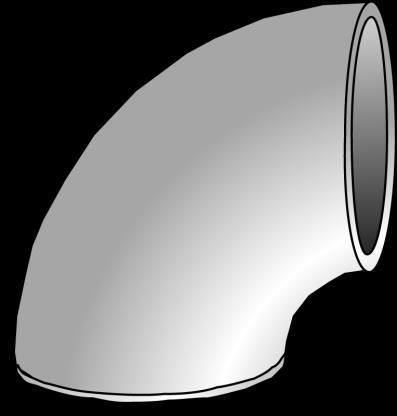
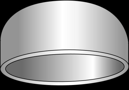
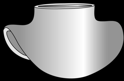

25 Various Fittings 45 Elbow 90 Short Radius Elbow Saddle Tee Cap Concentric Reducer Tee Flange Section 5 Water Piping Components and Accessories
 Spring Lever/ Notched Plate Used for shutoff and throttling duty")
 Low cost, low pressure drop Disc Section 5 Water Piping Components")
26 Butterfly Valve (General Purpose) Used on larger pipe sizes (2½ in. and larger) Spring Lever/ Notched Plate Used for shutoff and throttling duty Threaded Lug Soft Seat Durable design, suitable for frequent operation (opening and closing) Low cost, low pressure drop Disc Section 5 Water Piping Components and Accessories


27 Gate Valve (Shutoff Duty) Gate valves are also known as stop valves Handwheel Stem Gland Not used for throttling duty Waterflow Packing Seat Disc Body Section 5 Water Piping Components and Accessories


28 Globe Valve (Balancing Duty) Handwheel Stem Gland Packing Plug Body Seat Ring Waterflow Body Section 5 Water Piping Components and Accessories


29 Angle Type (Balancing Duty) Handwheel Angle valves can replace an elbow fitting Stem Gland Packing This is the same basic design as a globe valve Seat Plug Body Section 5 Water Piping Components and Accessories


30 Y Type Valve (Balancing Duty) Stem Wheel Bushing Bonnet Waterflow Seat Body Plug Packing Section 5 Water Piping Components and Accessories


31 Plug Valve (Balancing) Stem Plug valves are used for balancing duty on smaller flow applications Waterflow Plug Flow Opening Body Section 5 Water Piping Components and Accessories


32 Ball Valve (Open/Close Service) Low cost High capacity Low leakage Tight sealing Waterflow Section 5 Water Piping Components and Accessories


33 Service Cap Body Swing Check Valve Horizontal use or vertical upward flow use only Swing Mechanism Plug Seat Waterflow Section 5 Water Piping Components and Accessories

34 Lift Check Valve Lift Mechanism Waterflow Section 5 Water Piping Components and Accessories


35 Control Valves Valve Actuator 3-Way Diverting 2 outlets 1 inlet 3-Way Mixing 2 inlets 1 outlet Section 5 Water Piping Components and Accessories 2-Way Modulating


36 Circuit Setter TM Circuit Setters TM allow for pre-set balancing of waterflow Section 5 Water Piping Components and Accessories


37 Triple Duty Valve TM Triple Duty Valve TM on pump discharge Combines shutoff, balancing, and check valve into one assembly Section 5 Water Piping Components and Accessories
38 Relative Valve Comparison Chart Relative Valve Comparison Chart $ Size Ball 1 Gate 2 Globe 2 Swing Check 1 Wafer Butterfly 3 Lug Butterfly 3 ¼ ½ Notes: 1. All sizes threaded bronze body 2. Sizes ¼ to 2-in. threaded bronze body; sizes 3 to 6-in. threaded iron body 3. All sizes cast iron body Section 5 Water Piping Components and Accessories
39 Hydronic System Components Strainers Expansion Tanks Air Separators Air Vents Thermometers, Gauges, Pete s Plugs Pipe Supports Volume Tanks Section 5 Water Piping Components and Accessories


40 Y Strainer Waterflow one direction only Strainers are most important in open loop systems Mesh Strainer Section 5 Water Piping Components and Accessories


41 Expansion Tanks Open to atmosphere Air Space Compressed Air Diaphragm Overflow Open Tank Open to air Air-water interface Drain Closed Tank Very popular Captured air space Air-water interface Closed Diaphragm Tank Flexible membrane No air-water interface Very popular Section 5 Water Piping Components and Accessories
 Section 5 Water Piping Components and Accessories")
42 Diaphragm Expansion Tank System Connection Charging Valve Very Popular Most Cost Effective Diaphragm Lifting Ring Drain (Not Shown) Section 5 Water Piping Components and Accessories


43 Air Separator Inlet Tangential flow-thru design Stainless Steel Air Collector Tube Baffle Vessel Shell (3 times the nominal inlet/outlet pipe diameter) Outlet NPT, Grooved or Flanged Connections Vertical Strainer with Bottom Access Section 5 Water Piping Components and Accessories


44 Air Vents Manual or Automatic Air Vent From Terminal Coil Service Valve 4 Pipe Diameters Locate at high points Typical Locations: Risers Coils Terminals Section 5 Water Piping Components and Accessories To Return Main
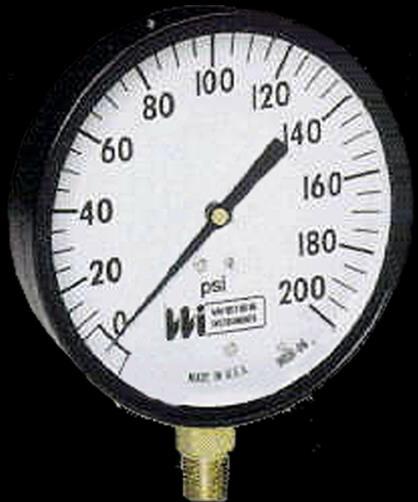
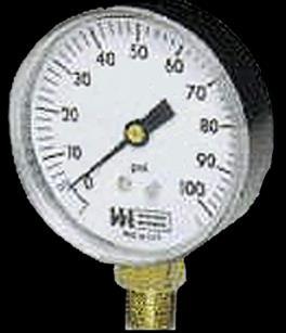

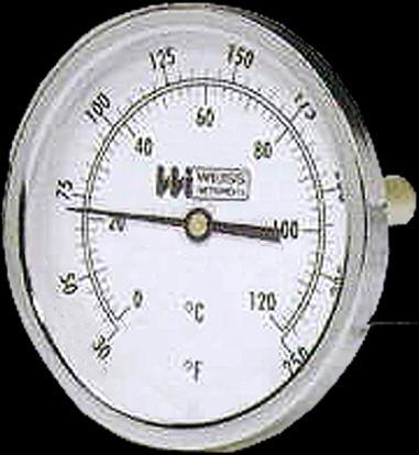
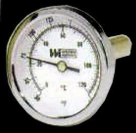

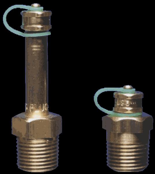
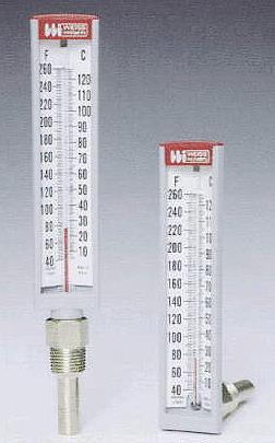
45 Thermometers, Gauges and Pete s Plug Pete s Plugs: Temperature and Pressure Ports Locate thermometers and gauges at inlets and outlets of equipment Section 5 Water Piping Components and Accessories
46 Pipe Hangers and Anchors 100 ft of 4-Inch Schedule 40 Black Steel Pipe Recommended Support Spacing for Schedule 40 Pipe Nominal Pipe Size (in.) Distance Between Supports (ft) ¾ - 1¼ 8 1½ - 2½ ½ How many pipe hangers are needed and what is their support distance? Distance between hangers is 14 ft Number of hangers = (100/14) = 7 Section 5 Water Piping Components and Accessories


47 Check for Volume Tank Requirements Rule of thumb for chilled-water systems: Suggested volume tank designs 3 gallons per nominal ton of chiller for normal air-conditioning duty 6 to 10 gallons per nominal ton of chiller for process duty or low ambient unit operation Section 5 Water Piping Components and Accessories
48 SECTION 6 WATER PIPING AND PUMPS Typical Piping Details at Equipment

49 Typical Piping Details at Equipment Piping details may vary based on the equipment used and the application. This TDP shows the details of commonly used methods. However, the methods shown do not reflect all specific project requirements. Follow manufacturer s installation literature. Section 6 Typical Piping Details at Equipment
50 Typical Piping Details At Equipment: Water-Cooled Chiller Air-Cooled Chiller Coil Piping Pump Piping Expansion Tank and Air Separator Parallel and Series Chillers Single Chiller System Multiple Chiller Systems Primary-Secondary System Primary-Only Variable Flow System Section 6 Typical Piping Details at Equipment
51 Typical Water-Cooled Chiller Piping Detail Supply Return Shutoff Valves Supply Return Thermometer (Typical) Water-Cooled Chiller Condenser Water Drain Valve Drain Flange (Typical) Valve Pressure Gauge (Typical) Strainer (if pump is on return side of chiller) Chilled Water Section 6 Typical Piping Details at Equipment
 Shutoff Valve (Typical) Section 6 Typical Piping Details at")
52 Typical Air-Cooled Chiller Piping Detail Air-Cooled Chiller Return Supply Pressure Gauge (Typical) Drain Valve Thermometer (Typical) Shutoff Valve (Typical) Section 6 Typical Piping Details at Equipment
 Return Shutoff Valve")
 Air-Handling Unit Coil Flange or Union Drain Valve Section 6 Typical Piping Details at")
53 Typical Coil Piping Detail (Chilled-Water or Hot Water) Shutoff Valve Bypass Line used with 3-way mixing valve only Supply Balancing Valve (used with mixing valve) Return Shutoff Valve Control Valve (2-Position On/Off, 2-Way Modulating or 3-Way Mixing) Balancing Valve Pete s Plug (Typical) Air-Handling Unit Coil Flange or Union Drain Valve Section 6 Typical Piping Details at Equipment
54 Typical Pump Piping Detail Return (Suction) Supply (Discharge) Shutoff Valve Check Valve Shutoff Valve Balancing Valve or Multi-Purpose Valve Flex Connectors Gauge or Pete s Plug (typical) Long Radius Elbow Drain Valve Strainer Minimum of 5 pipe diameters for end suction pumps Section 6 Typical Piping Details at Equipment


55 Typical Expansion Tank & Air Separator Piping Detail Pressure Reducing Valve w/check From Building Return Air Vent Air Separator Shutoff Valve Makeup Water Blow Down Valve Air Vent To System Expansion Tank Shutoff Valve Note: Each manufacturer has a slightly different piping arrangement. Follow the manufacturer s piping instructions for actual installation and pipe sizing. Pump Section 6 Typical Piping Details at Equipment
56 SECTION 7 WATER PIPING AND PUMPS System Piping Arrangements

57 System Piping Arrangements System piping arrangements may vary based on the equipment used and the application. The piping arrangements shown are schematics of commonly used methods. However, the methods shown do not reflect all specific project requirements. Follow manufacturer s installation literature. Section 7 System Piping Arrangements
58 Typical Piping Details System Piping Arrangements: Water-Cooled Chiller Air-Cooled Chiller Coil Piping Pump Piping Expansion Tank and Air Separator Parallel and Series Chillers Single Chiller System Multiple Chiller Systems Primary-Secondary System Primary-Only Variable Flow System Section 7 System Piping Arrangements
59 Parallel and Series Evaporators Parallel (Typically 18 F drop or less) 44 F 54 F 44 F 44 F Series (Typically greater than 18 F drop) 64 F 54 F 44 F Section 7 System Piping Arrangements

60 Single Chiller Cooling Tower Cooling Tower Air Handling Unit Water-Cooled Chiller Condenser Water Pump Chilled Water Pump Section 7 System Piping Arrangements
61 Multiple Chiller Dedicated Pumps Air Handling Units Cooling Tower Cooling Tower Water-Cooled Chiller Condenser Water Pump Chilled Water Pump Condenser Water Pump Water-Cooled Chiller Chilled Water Pump Section 7 System Piping Arrangements
62 Multiple Chiller Manifolded Pumps Air Handling Units Cooling Tower Equalization Line Cooling Tower Water-Cooled Chiller Automatic Isolation Valves Chilled Water Pumps Condenser Water Pumps Water-Cooled Chiller Section 7 System Piping Arrangements
63 Multiple Chiller Series-Counteflow Section 7 System Piping Arrangements
64 Primary-Secondary System Production Loop (primary) Building System Loop (secondary) Hydraulic Decoupler (Bridge) Alternate Bypass Line minimum chiller flow Secondary pumping station One pump active, the other standby (lead-lag) Pumps are VFD-equipped if all coils are 2-way Matches secondary flow to coil loads Hydraulic decoupler maintains constant primary flow Section 7 System Piping Arrangements
65 Primary-Only Variable-Flow Automatic Isolation Valves Control Valve, sized for minimum chiller flow Bypass Flow Meter Variable Speed Primary Pumps Section 7 System Piping Arrangements
66 Chiller Head Pressure Control with Diverting Valve Cooling Tower Method 1 Water-Cooled Chiller Condenser Water Pump Diverting Valve Section 7 System Piping Arrangements
67 Chiller Head Pressure Control with 100% Condenser Flow Cooling Tower Method 2 Diverting Valve Water-Cooled Chiller Condenser Water Pump Section 7 System Piping Arrangements


68 Chiller Head Pressure Control with Modulating Valve Cooling Tower Method 3 Modulating Valve Water-Cooled Chiller Condenser Water Pump Section 7 System Piping Arrangements
69 SECTION 8 WATER PIPING AND PUMPS Pump Basics and Types of Pumps
70 Pump Terms Capacity: Volume flow measured in gallons per minute (gpm) Head: Pressure at the base of a column of water is usually measured by the height of the water column in feet Feet Pressure Section 8 Pump Basics and Types of Pumps
71 Pumping Head Hd Hs Hd Hu Hs Closed System (evaporator) Suction head is Hs Discharge head is Hd Hs = Hd Pump must overcome friction loss of the piping circuit only Open System (condenser) Discharge head = Hd Unbalanced head = Hu Suction head = (Hd - Hu) Pump overcomes friction losses plus Hu Section 8 Pump Basics and Types of Pumps
72 Net Positive Suction Head (NPSH) (P) Pressure at Suction Flange Pump Discharge A minimum positive pressure (P) at the pump suction flange is required to prevent cavitation, which is the formation of vapor bubbles. Impeller Eye Section 8 Pump Basics and Types of Pumps


73 Typical Pump Cross-Section Coupler Suction Bearings Mechanical Seal Motor Centrifugal Impeller Coupler Discharge Section 8 Pump Basics and Types of Pumps
 Steep pump curve Head varies significantly as flow changes More applicable in open circuits (tower) where high")
74 Head - ft Flat Versus Steep Pump Curve Characterized by the slope of the pump curve Flat or steep Flat Pump Curve Steep Pump Curve Flow - gpm Flat pump curve Head varies slightly as flow changes More applicable on closed systems where variable flow may be used (chilled water circuit) Steep pump curve Head varies significantly as flow changes More applicable in open circuits (tower) where high head with constant flow may exist Section 8 Pump Basics and Types of Pumps
 Very Steep Capacity - gpm Good for HVAC Steep pump curve Head varies significantly as flow changes More applicable in open circuits (tower)")
75 Head - ft Desirable Head - Capacity Curve Very Flat Characterized by the slope of the pump curve Flat or steep Flat pump curve Head varies slightly as flow changes More applicable on closed systems where variable flow may be used (chilled water circuit) Very Steep Capacity - gpm Good for HVAC Steep pump curve Head varies significantly as flow changes More applicable in open circuits (tower) where high head with constant flow may exist Section 8 Pump Basics and Types of Pumps


76 Crossover Point of Pump and System Curves Head - ft Shutoff Pump Curve Full Flow System Curve Pipe Friction Head Static Head Capacity - gpm Section 8 Pump Basics and Types of Pumps

77 Effect of Overestimating Pump Head Head - ft Pump Head- Capacity Curve Design gpm against overestimated head System Head Actual bhp Actual gpm against actual head Estimated bhp Capacity - gpm Section 8 Pump Basics and Types of Pumps

78 Parallel Pumps (Two Identical Pumps) H Single Pump Curve Parallel Pump Curve gpm 2 gpm 2 gpm 1 gpm 1 Two identical pumps in parallel Resulting gpm doubles Plot result to obtain parallel pump curve gpm Section 8 Pump Basics and Types of Pumps
79 Series Pumps (Two Identical Pumps) H 1 H 2 Single Pump Curve Head 1 Series Pump Curve Head 1 Head 2 Head 2 Two identical pumps in series Resulting head doubles Plot result to obtain series pump curve gpm Section 8 Pump Basics and Types of Pumps
 According to the pump affinity laws the")
80 Variable Speed Pumping System Curve Constant Speed Pump Curve bhp 2 = bhp 1 (rpm 2 / rpm 1 ) 3 Where: bhp = brake horsepower Capacity - gpm As control valves modulate, the differential pressure across supply and return lines rises sending signal to VFD to modulate pump speed Operating point moves along system curve to new rpm line (points A - B - C) According to the pump affinity laws the energy savings is a cubed function of the ratio of the pump speeds Section 8 Pump Basics and Types of Pumps
81 Pump Selection Process 1. Determine cooling or heating loads to be pumped 2. Find load gpm from equipment selections 3. Find total pumping gpm 4. Establish most resistant pumping path in loop 5. Select pump from manufacturer s data 6. Flat curved pumps for closed systems with control valves 7. Steep curved pumps for open systems 8. Find final operating point 9. Check for start-up conditions 10. Select motor accordingly Section 8 Pump Basics and Types of Pumps


82 Electronic Pump Selection 100 ft 1000 gpm Screen Capture courtesy of: Suction Size = 6 Max Imp Dia = 9 Design Capacity = ITT Bell & Gossett Discharge Size = 5 Max Imp Dia = 11 Design Head = Feet 8200 N. Austin Cut Dia = Motor Size = 40 HP Morton Grove, Il Section 8 Pump Basics and Types of Pumps


83 In-Line Pump Small capacity design Motor Pump Assembly Section 8 Pump Basics and Types of Pumps

84 Close-Coupled Pump Internal Self-Flushing Seal Section 8 Pump Basics and Types of Pumps


85 Base-Mounted End Suction Pump Discharge Short Shaft Coupling Guard Motor Suction Welded Steel Frame provides support and installation ease Section 8 Pump Basics and Types of Pumps


86 Double-Suction Vertical Split Case Pump Vertical Suction and Discharge Large-capacity designs for chillers and cooling towers Section 8 Pump Basics and Types of Pumps


87 Double-Suction Horizontal Split Case Pump Pump Coupling Guard Motor Large-capacity design for chillers and cooling towers Section 8 Pump Basics and Types of Pumps
88 Pump Type Comparison Pump Type Cost Flow & Head Capability Space Required Ease of Service In Line Least ft Least 1 Poor 5 Close- Coupled End Suction Vertical Split Case Horizontal Split Case 2 2, ft , ft , ft 4 2 Highest 5 40, ft Most 5 Good 3 Section 8 Pump Basics and Types of Pumps
89 SECTION 9 WATER PIPING AND PUMPS Pump Sizing and Pump Selection Example
90 Pipe Sizing and Pump Selection Example Given: Chiller 100 Tons 12.4 ft Cooler Pressure Drop 11.0 ft Condenser Pressure Drop 22.6 gals, Cooler Water Volume AHU-1 AHU-2 45-Ton Load 9.9 ft Pressure Drop 55-Ton Load 13.4 ft Pressure Drop Find: Entering Chilled Water Leaving Chilled Water Entering Condenser Water Leaving Condenser Water Air Separator Pressure Drop Pipe Sizes Pump Head & Flow If a volume tank is required 54 F 44 F 85 F 95 F 1.3 ft Section 9 Pump Sizing and Pump Selection Example
91 Step 1 - Determine Water Velocity in the Piping Service Recommended Water Velocities Velocity Range (fps) Pump discharge 8 to 12 Pump suction 4 to 7 Drain line 4 to 7 Header 4 to 15 Mains and Riser 3 to 10 Branches and Runouts 5 to 10 City water 3 to 07 Section 9 Pump Sizing and Pump Selection Example
92 Step 2 Determine Piping Friction Losses Section 9 Pump Sizing and Pump Selection Example Chart 1 - Friction Loss for Closed-Loop System Schedule 40 Steel Pipe Chart 2 - Friction Loss for Open-Loop System Schedule 40 Steel Chart 3 - Friction Loss for Open and Closed Copper Tubing System (Type M) Table 5 - Friction Loss of Valves Table 6 - Friction Loss of Pipe Fittings Table 7 - Friction Loss of Special Fittings Table 8 - Friction Loss Control Valves and Strainers
93 Step 3 - Gather Specific Component Pressure Drops Chiller 30 Series Cooler PD 12.4 ft wg Condenser PD 11.0 ft wg AHU-1 39 Series Cooling Coil PD 9.9 ft wg AHU-2 39 Series Cooling Coil PD 13.4 ft wg Tower From BAC Unbalanced head 6.5 ft wg Air Separator Required Nozzle Pressure From Bell and Gossett From Product Literature 12.5 ft wg 1.3 ft wg Section 9 Pump Sizing and Pump Selection Example
94 Step 4 Review Piping Layout and Calculate GPMs Cooling Tower 3 Condenser Loop gpm 28 5 H 150 gpm per pump C Water-Cooled Chiller Located on ground floor Section 9 Pump Sizing and Pump Selection Example


95 Step 5 Size Pipe & Find Friction Rate for Condenser Water Loop Using Chart 2, size the pipe and find the friction rate per 100 ft Section 9 Pump Sizing and Pump Selection Example
96 Step 6 Find Longest Circuit Pressure Drop Cooling Tower 3 Condenser Loop Find longest circuit pressure drop by adding all fittings and pipe lengths gpm 28 5 H C Water-Cooled Chiller Located on ground floor Section 9 Pump Sizing and Pump Selection Example
97 Step 7 Sum Pressure Drops for Pump Selection Friction Head 36.0 ft wg Unbalanced Head 6.5 ft Pressure Drop-Thru Condenser 11.0 ft Cooling Tower Nozzles 12.5 ft Total Pump Head gpm Each condenser pump handles 66 ft at 150 gpm Section 9 Pump Sizing and Pump Selection Example

98 Step 7 (Cont d) Computerized Pump Selection Individual Pump Selection 66 ft 150 gpm Screen Capture courtesy of: Pump Series: 1510 Max Imp Dia = 7 Design Capacity = ITT Bell & Gossett Suction Size = 2.5 Max Imp Dia = 9.5 Design Head = N. Austin Discharge Size = 2 Cut Dia = Motor Size = 5 HP Morton Grove, Il Section 9 Pump Sizing and Pump Selection Example


99 Step 7 (Cont d) Computerized Pump Selection Parallel (2) Pump Selection 66 ft Pump Series: 1510 Max Imp Dia = 7 Design Capacity = ITT Bell & Gossett Suction Size = 2.5 Max Imp Dia = 9.5 Design Head = N. Austin Discharge Size = 2 Cut Dia = Motor Size = 5 HP Morton Grove, Il The Power and Eff. Curves shown are only for single pump operation. Section 9 Pump Sizing and Pump Selection Example 300 gpm Screen Capture courtesy of:


100 Step 8 Size Pipe & Find Friction Rate for Chilled Water Loop Section 9 Pump Sizing and Pump Selection Example


101 Step 8 Size the Chilled Water Loop Chilled Water Loop Water-Cooled Chiller AHU gpm AHU gpm gpm 10 5 C Air Handling Units Way Mixing Valve N 5 1 Air Separator 2 Section 9 Pump Sizing and Pump Selection Example
102 Step 8 (Cont d) Sum Pressure Drops for Pump Friction Head 15.5 ft wg Pressure Drop Thru Cooler 12.4 ft Pressure Drop Thru Air Separator 1.3 ft Pressure Drop Thru AHU # ft Total Pump Head gpm Each chilled water pump handles 42.6 ft at 120 gpm Section 9 Pump Sizing and Pump Selection Example


 300 gallons")

103 Step 9 Check Evaporator Loop Volume 100-ton chiller 3 gallons/ton = 300 gallons required Total number of gallons in the system = (see text) 300 gallons required gallons = gallon volume tank necessary

104 System Syzer Calculator Section 9 Pump Sizing and Pump Selection Example
105 SECTION 10 WATER PIPING AND PUMPS Summary
106 Summary Compared the 3 types of piping systems Identified the 4 types of water distribution systems Differentiated between direct return and reverse return systems Identified the various valves and hydronic accessories available for use in piping systems Diagrammed typical piping hookups for chillers, pumps, and cooling towers Sized the piping for a closed and an open-loop system Identified the types of water pumps, their features, and the selection process Section 10 Summary
107 Work Session WATER PIPING AND PUMPS Work Session 1. A chilled water system is a loop system. 2. A condenser water system with a cooling tower is a loop system. 3. What are the 4 types of valves that can be used for balancing/throttling? Work Session
108 Technical Development Program Thank You This completes the presentation. TDP 502 Water Piping and Pumps Artwork from Symbol Library used by permission of Software Toolbox
Chiller Plant Design. Julian R. de Bullet President debullet Consulting
 Chiller Plant Design Julian R. de Bullet President debullet Consulting 703-483-0179 julian@debullet.com This ASHRAE Distinguished Lecturer is brought to you by the Society Chapter Technology Transfer ASHRAE
DISTRIBUTION SYSTEMS. Water Piping and Pumps
 DISTRIBUTION SYSTEMS Water Piping and Pumps Technical Development Programs (TDP) are modules of technical training on HVAC theory, system design, equipment selection and application topics. They are targeted
DISTRIBUTION SYSTEMS. Water Piping and Pumps
 DISTRIBUTION SYSTEMS Water Piping and Pumps Technical Development Programs (TDP) are modules of technical training on HVAC theory, system design, equipment selection and application topics. They are targeted
TECHNICAL. Series 18. Pump Packages
 TECHNICAL S Y S T E M S Series 18 Pump Packages Series 18 Pump Packages Standard Features Close-coupled, end-suction, centrifugal pumps Mounted and wired pump starters Hand-Off-Auto switch for each pump
Technical Development Program COMMERCIAL HVAC SYSTEMS. Water Source Heat Pump Systems PRESENTED BY: Ray Chow. Sales Engineer
 Technical Development Program PRESENTED BY: COMMERCIAL HVAC SYSTEMS Water Source Heat Pump Systems Ray Chow Sales Engineer TDP Updates Menu Section 1 Section 2 Section 3 Section 4 Section 5 Section 6 Section
DENVER PUBLIC SCHOOLS DESIGN AND CONSTRUCTION STANDARDS This Standard is for guidance only. SECTION PUMPS
 PART 0 A/E INSTRUCTIONS 0.01 Design Requirements A. Pumping system design 1. A primary-secondary pumping system is preferred. Redundant pipes are required for chillers and boilers. 2. Select pumps to operate
D. NEMA Compliance: Provide electric motors and components which comply with NEMA standards.
 PART 1: GENERAL 1.01 Purpose: A. This standard is intended to provide useful information to the Professional Service Provider (PSP) to establish a basis of design. The responsibility of the engineer is
PhiloWilke Partnership Addendum No. 2 A/E Project No April 2016
 SECTION 23 21 23 PART 1 - GENERAL 1.01 RELATED DOCUMENTS A. Drawings and general provisions of the Contract, including General Conditions and Division 01 Specification Sections, apply to this Section.
C. ASSE 1013: Performance Requirements for Reduced Pressure Principle Backflow Preventers.
 SECTION 22 10 00 PLUMBING PIPING AND PUMPS PART 1 - GENERAL 1.1 Purpose: A. This standard is intended to provide useful information to the Professional Service Provider (PSP) to establish a basis of design.
UNIVERSITY OF MISSOURI Building Hydronic Piping and Pump Systems 2017 Q3
 GENERAL: Hydronic systems included in this document are chilled water, heating hot water, dual temperature and glycol based systems. DESIGN GUIDELINES: Design General 1. Where campus steam is available,
B. Unit construction shall comply with ASHRAE 15 Safety Code, NEC, and ASME applicable codes (U.S.A. codes).
.") Guide Specifications PART 1 GENERAL 1.01 SYSTEM DESCRIPTION Microprocessor controlled, air-cooled liquid chiller utilizing scroll compressors, low sound fans, hydronic pump system and optional fluid storage
Guide Specifications PART 1 GENERAL 1.01 SYSTEM DESCRIPTION Microprocessor controlled, air-cooled liquid chiller utilizing scroll compressors, low sound fans, hydronic pump system and optional fluid storage
B. HI Compliance: Design, manufacture, and install pumps in accordance with HI "Hydraulic Institute Standards."
 PART 1: GENERAL 1.01 Purpose: A. This standard is intended to provide useful information to the Professional Service Provider (PSP) to establish a basis of design. The responsibility of the engineer is
Essex County College - West Essex Campus Addition And Renovations dib # / SECTION HYDRONIC PIPING SPECIALTIES PART 1- GENERAL
 Essex County College - West Essex Campus Addition And Renovations dib # 54292 / 11-14 SECTION 232116 - HYDRONIC PIPING SPECIALTIES PART 1- GENERAL 1.1 RELATED DOCUMENTS A. Drawings and general provisions
University of Delaware
 SECTION 23 21 23_HYDRONIC PIPING SYSTEMS ABOVE GRADE PART 1 GENERAL 1.1 SUMMARY University Contact: Energy & Engineering Group (302) 831-1744 This standard includes hydronic piping requirements for both
Series 1140 and 1141 Temperature Regulators
 Hoffman Specialty Installation & Maintenance Instructions HS-504(E) Series 1140 and 1141 Temperature Regulators! CAUTION FOLLOW ALL INSTALLATION AND OPERATING INSTRUCTIONS. TURN OFF WATER OR STEAM BEFORE
SECTION PUMPS. 6. Section Steam and Condensate Piping and Specialties.
 SECTION 15540 PUMPS PART 1 GENERAL 1.01 SUMMARY A. Section Includes: 1. Base Mounted Pumps. 2. Horizontal Split Case Pumps. 3. In line Pumps. 4. Steam Condensate Return Pumps. B. Related Sections: 1. Section
A. ASME Compliance: Fabricate and install hydronic piping in accordance with ASME B31.9 "Building Services Piping.
 PART 1: GENERAL 1.01 Purpose: A. This standard is intended to provide useful information to the Professional Service Provider (PSP) to establish a basis of design. The responsibility of the engineer is
Domestic Pump Condensate Transfer Equipment
 Bulletin S-944L Domestic Pump Condensate Transfer Equipment CONDENSATE RETURN UNITS BOILER FEED UNITS LOW NPSH PUMPS VACUUM HEATING UNITS INDUSTRIAL VACUUM UNITS www.domesticpump.com Condensate Return
A hydronic system controls comfort by delivering heated or cooled fluid to the conditioned space through pipes.
 Introduction to Hydronics A hydronic system controls comfort by delivering heated or cooled fluid to the conditioned space through pipes. Hydronic heating systems use hot water or steam to deliver the
HVAC BASIC MATERIAL AND METHODS 1.01 RELATED CORNELL DESIGN AND CONSTRUCTION STANDARDS
 230500 HVAC BASIC MATERIAL AND METHODS PART 1 GENERAL 1.01 RELATED CORNELL DESIGN AND CONSTRUCTION STANDARDS A. Section 230000 Basic HVAC Requirements B. Section 230523 Valves C. Section 230510 Chilled
Division 23 - HVAC Switzerland Beallsville K-12. Section HYDRONIC PIPING SECTION HYDRONIC PIPING PART 1 - GENERAL
 Division 23 - HVAC 090070 Switzerland Beallsville K-12 Section 23 21 13 HYDRONIC PIPING SECTION 23 21 13 HYDRONIC PIPING PART 1 - GENERAL 1.1 RELATED DOCUMENTS A. Drawings and General Provisions of the
Technical Data TYPE T14 & T14D TEMPERATURE PILOT SPENCE ENGINEERING COMPANY, INC. 150 COLDENHAM ROAD, WALDEN, NY SD 4511A T14 PILOT
 Technical Data SD 4511A SPENCE ENGINEERING COMPANY, INC. 150 COLDENHAM ROAD, WALDEN, NY 12586-2035 TYPE T14 & T14D TEMPERATURE PILOT PRINTED IN U.S.A. SD 4511A/9811 5 13 /16 D 4 7 /8 1 13 /16 T14 PILOT
Fans: Features and Analysis
 Technical Development Program COMMERCIAL HVAC EQUIPMENT Fans: Features and Analysis PRESENTED BY: Michael Ho Version 1.2 Menu Section 1 Section 2 Section 3 Section 4 Section 5 Section 6 Section 7 Section
SECTION GENERAL-SERVICE COMPRESSED-AIR SYSTEMS
 PART 1 GENERAL 1.01 SECTION INCLUDES A. Pipe and Pipe Fittings. B. Air compressor. C. Air receiver and accessories. D. Aftercooler. E. Refrigerated air dryer. F. Pressure reducing station. 1.02 RELATED
union swing check valve spring loaded check valve purging valve pressure relief valve relief valve metered balancing valve
 VENT APPENDIX A: PIPING SYMBOL LEGEND GENERIC COMPONENTS CALEFFI COMPONENTS circulator circulator w/ ThermoBloc union circulator w/ swing check spring loaded balancing balancing w/ gate check globe s purging
4. Provide brass valve tags marked for the service. See pertinent service specification for valve type.
 Section includes various guidelines for valves, instrumentation for process systems, meters, thermometers, and gauges. This design guideline is written to the designer of record (DOR). This guideline is
Fans and Pumps I. Dr. Sam C. M. Hui Department of Mechanical Engineering The University of Hong Kong
 MEBS6008 Environmental Services II http://www.mech.hku.hk/bse/mebs6008/ Fans and Pumps I Dr. Sam C. M. Hui Department of Mechanical Engineering The University of Hong Kong E-mail: cmhui@hku.hk Sep 2012
Hoffman Specialty Pump Products
 Condensate Units Boiler Feed Units Vacuum Heating Units Hoffman Specialty Pump Products S-0692C INDEX Condensate Return Units Series WC Series WCS Series SCC Boiler Feed Units Stock Watchman Condensate
SECTION HYDRONIC PIPING AND SPECIALTIES
 SECTION 15511 HYDRONIC PIPING AND SPECIALTIES PART 1 GENERAL 1.01 SUMMARY A. Section Includes: 1. Pipe Materials. 2. Fittings. 3. Specialty Items. 4. Glycol Antifreeze Protection. 5. Process Cooling B.
Commercial, Residential & Institutional Pumps, Tanks, & Accessories
 Taco International Commercial, Residential & Institutional Pumps, Tanks, & Accessories Taco Catalog # : 300-6.0 Supersedes: 300-3.5 9/11/06 Effective Date: 03/21/07 Printed in USA Pumps FI Frame Mounted
PRESSURE INDEPENDENT CONTROL VALVE TECHNOLOGY. 3/16/2012 Fred Ferrara 1
 PRESSURE INDEPENDENT CONTROL VALVE TECHNOLOGY 3/16/2012 Fred Ferrara 1 Typical Hydronic System Problems Low Delta T s resulting in: 1. Chillers operating at higher capacities and/or longer than necessary
CENTRIFUGAL PUMPS. STATE the purposes of the following centrifugal pump components:
 Pumps DOE-HDBK-1018/1-93 CENTRIFUGAL PUMPS CENTRIFUGAL PUMPS Centrifugal pumps are the most common type of pumps found in DOE facilities. Centrifugal pumps enjoy widespread application partly due to their
SECTION SECTION DESIGN REQUIREMENTS
 SECTION 26 09 SECTION 23 05 23 DESIGN REQUIREMENTS GENERAL DUTY VALVES GENERAL INFORMATION 1.1 This section applies to valves for hydronic and steam systems. DESIGN REQUIREMENTS 2.1 Design Criteria a.
Trim Pump Impellers. Fredrick/Weinman Engineered Products 2-1/2 KH, 2-1/2 x 3 x 12
 Head, ft. w.c. Trim Pump Impellers TRIM THE PUMP IMPELLER SO THE FLOW PRODUCED MATCHES THE DESIGN REQUIREMENT WITH THE DISCHARGE SERVICE VALVE WIDE OPEN. IN MOST CASES, THIS WILL REDUCED THE PUMP ENERGY
Update In Progress. Division 23 Heating, Ventilation, and Air Conditioning Page Section FLUID SYSTEMS EQUIPMENT PART 1 GENERAL
 Section 23 20 00 FLUID SYSTEMS EQUIPMENT PART 1 GENERAL 1. CHILLERS Page 23 20 00-1 A. Provide chiller packages with centrifugal compressors, or screw compressors, and water cooled condensers. B. Design
Threaded. Flanged. Model PSH. Primary Secondary Header A-451
 Threaded Flanged Model PSH Primary Secondary Header A-451 The History of Primary-Secondary Pumping Did you know that Bell & Gossett invented Primary-Secondary Pumping? This widely popular pumping arrangement
Chiller Plant Design. Application Guide AG McQuay International. Elevation Difference. Column Height When Pump Is Off
 Application Guide AG 31-003-1 Chiller Plant Design 51.5F Return Water To Chiller Two 400 Ton Chillers Each At 300 Tons (Balanced Load) 51.5F 480 gpm Flow Through Decoupler 44F 54F Building Load 600 Tons
CHILLED WATER SYSTEM 1.01 RELATED CORNELL DESIGN AND CONSTRUCTION STANDARDS. B. Section HVAC Basic Materials and Methods
 230510 CHILLED WATER SYSTEM PART 1: GENERAL 1.01 RELATED CORNELL DESIGN AND CONSTRUCTION STANDARDS A. Section 230000 Basic HVAC Requirements B. Section 230500 HVAC Basic Materials and Methods C. Section
PROJ. NO SECTION REFRIGERANT PIPING
 SECTION 23 23 00 REFRIGERANT PIPING PART 1 - GENERAL 1.1 RELATED DOCUMENTS A. Drawings and general provisions of the Contract, including General and Supplementary Conditions and Division 01 Specification
1900 Series In-Line Pump
 Water Circulation Pumps & Circulators 1900 Series In-Line Pump HYDRONIC COMPONENTS & SYSTEMS Taco Catalog #: 300-1.4 Supersedes: 300-1.4 Dated: 06/15/95 Effective Date: 03/15/05 Printed in USA 2. Features
1.1 This section applies to air handling units for HVAC Systems.
 AIR HANDLING UNITS GENERAL INFORMATION 1.1 This section applies to air handling units for HVAC Systems. DESIGN REQUIREMENTS 2.1 Design Criteria a. The decision to use modular central station air handling
DIVISION 15 MECHANICAL
 DIVISION 15 MECHANICAL A. GENERAL DESIGN CONDITIONS 1. Design occupied spaces to maintain 72 F and a space dew point temperature not to exceed 55 F. 2. Design classroom and office space buildings with
A. Operation and Maintenance Data: For pumps to include in emergency, operation, and maintenance manuals.
 SECTION 23 21 23 - HYDRONIC PUMPS PART 1 - GENERAL 1.1 RELATED DOCUMENTS A. Drawings and general provisions of the Contract, including General and Supplementary Conditions and Division 01 Specification
Appendix B. Symbols for Drawings. Table B.1. Air moving devices and ductwork symbols. Air Movement. Fans. Axial flow fan.
 Appendix B Symbols for Drawings Table B.1 Air moving devices and ductwork symbols Air Movement Fans Axial flow fan Centrifugal fan Propeller fan Intake roof ventilator (supply) Exhaust roof ventilator
.2 Section Waste Management and Disposal..5 Section Motors, Drives and Guards for Mechanical Systems.
 Issued 2006/08/01 Section 15131 Pumps Hydronic Systems Page 1 of 6 PART 1 GENERAL 1.1 RELATED SECTIONS.1 Section 01330 Submittal Procedures..2 Section 01355 Waste Management and Disposal.3 Section 01780
dualarm Vertical In-Line Pumps
 Series 430 & 438 dualarm Vertical In-Line Pumps FILE NO: 43d.1 DATE: Jan. 0, 010 SUPERSEDES: 43d.1 DATE: Sept., 008 Series 430 & 438 Smart pumps for the commercial HVAC market. Armstrong Vertical In-Line
Technical Development Program. COMMERCIAL HVAC PACKAGED EQUIPMENT Split Systems PRESENTED BY: Ray Chow Sigler
 Technical Development Program COMMERCIAL HVAC PACKAGED EQUIPMENT Split Systems PRESENTED BY: Ray Chow Sigler Menu Section 1 Section 2 Section 3 Section 4 Section 5 Section 6 Section 7 Introduction System
Flow Control for Fire Protection
 Flow Control for Fire Protection Valve Solutions From An Industry Leader AmesFireWater.com Count on the Fire Protection Leader for Reliable Flow Control Solutions Ames provides a range of high-quality
Survey. Water. Hydronic. Systems. Pre-Installation Survey and Checklist for Water Systems
 Water Hydronic Survey Systems Pre-Installation Survey and Checklist for Water Systems INSTALLATION SURVEY WATER A. INTRODUCTION 1. Use this survey to review the system for operating behavior and history.
JCseries EVAPORATIVE CONDENSER. engineering data
 JCseries EVAPORATIVE CONDENSER engineering data Recold JC Series Evaporative Condenser Contents 2 Construction... 3 Schematic... 4 Engineering Data... 5 Selection Procedure... 6-9 Multi-Circuited Selection
Series 4302 & FILE NO: 43d.12 DATE: June 1, 2004 SUPERSEDES: 43d.12 DATE: July 15, dualarm Vertical In-Line Pumps
 Series 0 & FILE NO: d. DATE: June, 00 SUPERSEDES: d. DATE: July, 00 dualarm Vertical In-Line Pumps dualarm Smart pumps for the commercial HVAC market Vertical In-Line pump, the best design for HVAC systems,
SERIES 24. Series 24 Features. Commercial, Forced Draft, Hot Water or Steam Boiler. The right fit for any commercial job
 SERIES Commercial, Forced Draft, Hot Water or Steam Boiler Sizes from to,8 MBH output The right fit for any commercial job The Series is built to handle any installation - businesses, institutions, apartments,
Domestic. Pump Series CB and CBE Condensate Units SINGLE OR DUPLEX 1,000 THRU 140,000 SQ. FT. EDR-250 THRU 34,748 LB./HR.
 Cast Iron Receivers: For years of dependable service; warranted for 20 years from date of shipment against failure due to corrosion. Each Receiver comes standard with Inlet connection, an overflow and
Technical Development Program
 Technical Development Program PRESENTED BY: James Parker Insert your logo here AIR HANDLERS Coils: Direct Expansion Chilled Water and Heating Menu Section 1 Introduction Section 2 Typical Coil Applications
B. Shop Drawings: Detail fabrication of pipe anchors, hangers, special pipe support assemblies, alignment guides, expansion joints and loops,
 SECTION 23 21 13 - PART 1 - GENERAL 1.1 RELATED DOCUMENTS A. Drawings and general provisions of the Contract, including General and Supplementary Conditions and Division 01 Specification Sections, apply
Flow Control for Fire Protection
 Flow Control for Fire Protection Valve Solutions From An Industry Leader AmesFireWater.com Count on the Fire Protection Leader for Reliable Flow Control Solutions Ames provides a range of high-quality
MODEL P. 2 ft. NPSH Cast Iron Bronze Fitted Low NPSH Centrifugal Pumps. BULLETIN 112 Revised 7/09. PH (Horizontal Flange Mounted)
") SHIPPENSBURG PUMP CO., INC. P.O. BOX 279, SHIPPENSBURG, PA 17257 PHONE 717-532-7321 FAX 717-532-7704 WWW.SHIPCOPUMPS.COM BULLETIN 112 Revised 7/09 PH (Horizontal Flange Mounted) MODEL P 2 ft. NPSH Cast
SHIPPENSBURG PUMP CO., INC. P.O. BOX 279, SHIPPENSBURG, PA 17257 PHONE 717-532-7321 FAX 717-532-7704 WWW.SHIPCOPUMPS.COM BULLETIN 112 Revised 7/09 PH (Horizontal Flange Mounted) MODEL P 2 ft. NPSH Cast
SECTION DOMESTIC WATER PUMPS
 SECTION 22 11 23 DOMESTIC WATER PUMPS PART 1 - GENERAL 1.1 SUMMARY A. Section includes the following all-bronze and bronze-fitted centrifugal pumps for domestic cold- and hot-water circulation: 1. Close-coupled,
D-11 OUTLINE SPECIFICATION FOR HTHW (ABOVE GRADE) HYDRONIC PIPING
 HYDRONIC PIPING") D-11 OUTLINE SPECIFICATION FOR HTHW (ABOVE GRADE) HYDRONIC PIPING PART 1 - GENERAL 1.1 RELATED DOCUMENTS A. Drawings and general provisions of the Contract, including General and Supplementary Conditions
D-11 OUTLINE SPECIFICATION FOR HTHW (ABOVE GRADE) HYDRONIC PIPING PART 1 - GENERAL 1.1 RELATED DOCUMENTS A. Drawings and general provisions of the Contract, including General and Supplementary Conditions
Brown University Revised August 3, 2012 Facilities Design & Construction Standards SECTION AIR HANDLING UNITS
 SECTION 23 70 00 AIR HANDLING UNITS PART 1. GENERAL 1.1 Section includes air-handling units to 15,000 cfm and accessories. 1.2 Related Sections 1 : A. Division 01 - Brown University Standard for Narragansett
SECTION HYDRONIC PIPING
 SECTION 23 21 13 HYDRONIC PIPING PART 1 - GENERAL 1.1 SUMMARY A. This Section includes pipe and fitting materials, joining methods, special-duty valves, and specialties for the following: 1. Hot-water
SECTION COMPRESSED AIR SYSTEM. A. Pipe and pipe fittings, including valves, unions and couplings.
 SECTION 15481 COMPRESSED AIR SYSTEM PART 1 - GENERAL 1.1 SECTION INCLUDES A. Pipe and pipe fittings, including valves, unions and couplings. B. Air compressor. C. After cooler. D. Refrigerated air dryer.
Silhouette. Feedwater Heater. Boiler Feedwater
 Roth Roth Low Low Silhouette Silhouette TRAY DEAERATORS Boiler Boiler Feedwater Feedwater Heater Heater Capacities Capacities to to 50,000 50,000 lb/hr lb/hr Model RDTV-150-5-1-2 vertical tray type deaerator
GT Series Single-Stage, Double Suction Horizontal Split Case Pumps
 Water Circulation Pumps & Circulators GT Series Single-Stage, Double Suction Horizontal Split Case Pumps GT Series Pumps provide the ultimate in reliability and ease of installation for heating, air conditioning,
HEAT GENERATION 1.01 RELATED CORNELL DESIGN AND CONSTRUCTION STANDARDS. B. Section HVAC Basic Materials and Methods
 230520 HEAT GENERATION Cornell s Design and Construction Standards provide mandatory design constraints and acceptable or required products for all construction at Cornell University. These standards are
Condenser Water Pump Calculator Guide
 Condenser Water Pump Calculator Guide Table of Contents 1.0 Introduction... 3 1.1 Units... 3 2.0 Disclaimer... 3 3.0 Overall Condenser Water System... 3 4.0 Condenser Water Pump Calculator - Inputs...
SECTION HEATING BOILER FEEDWATER EQUIPMENT
 SECTION 23 53 00 HEATING BOILER FEEDWATER EQUIPMENT PART 1 - GENERAL 1.1 SUMMARY A. Section includes boiler feedwater pumps, de-aerators, accessories, controls and tanks. 1.2 REFERENCES A. ASME (American
SECTION LABORATORY and DE-IONIZED WATER SYSTEMS STANDARD CONSTRUCTION STANDARD
 PART 1: GENERAL 1.01 Codes and Standards: A. Plumbing Code Compliance: Comply with applicable portions of National Standard Plumbing Code pertaining to selection and installation of Plumbing materials
BuildingName The Description of the Project P DOCUMENTS
 ARCHITECTURE, ENGINEERING AND CONSTRUCTION P00000000 0000 DOCUMENTS ARCHITECTURE & ENGINEERING 326 East Hoover, Mail Stop B Ann Arbor, MI 48109-1002 Phone: 734-764-3414 Fax: 734-936-3334 SPECIFICATION
SECTION DOMESTIC WATER PRESSURE BOOSTING SYSTEMS (VFD) PART 1 - GENERAL 1.1 SUMMARY
 PART 1 - GENERAL 1.1 SUMMARY") SECTION 22 11 23.13 DOMESTIC WATER PRESSURE BOOSTING PART 1 - GENERAL 1.1 SUMMARY A. Where utility water pressure cannot adequately meet the pressure requirements of the domestic water systems and where
SECTION 22 11 23.13 DOMESTIC WATER PRESSURE BOOSTING PART 1 - GENERAL 1.1 SUMMARY A. Where utility water pressure cannot adequately meet the pressure requirements of the domestic water systems and where
Water engineers and utilities are often
 FWRJ Horizontal or Vertical? High-Service Pump Selection Mark Ludwigson, Len Rago, and Jeff Greenfield Water engineers and utilities are often faced with a decision concerning the best type of pump when
Description of All Alternatives Considered-
 Description of All Alternatives Considered- Energy efficiency is an area where the Tubman design can be improved. The design heating load is 1807.8 MBH and the design cooling load is 1702.2 MBH or 142
Hard-hitting Contenders In HVAC Fluid Handling Solutions
 Hard-hitting Contenders In HVAC Fluid Handling Solutions Patterson Enters the HVAC Arena With a Reputation for Quality and Reliability! Applications for All Patterson HVAC Pumps Chill Water Condenser Water
THE PRODUCTS YOU NEED. THE QUALITY YOU WANT. THE INNOVATION YOU DESERVE.
 THE PRODUCTS YOU NEED. THE QUALITY YOU WANT. THE INNOVATION YOU DESERVE. Central Chillers & Pump Tanks C E N T R A L C H I L L E R S 30RAP Series Central Chillers 10-60 Tons 30RAP Series air-cooled central
SANTA ROSA FIRE DEPARTMENT FIRE PREVENTION BUREAU PLAN REVIEW CHECKLIST
 July 1, 2010 SANTA ROSA FIRE DEPARTMENT FIRE PREVENTION BUREAU PLAN REVIEW CHECKLIST FIRE PUMP REVIEW Address: Permit #: Inspector: Date: Status: Inspector: Date: Status: A-Approved; AC-Approved w/comments;
VSA SEWAGE PUMP. Capacities to 1600 gpm, Heads to 120, Horsepower range 3/4 thru 40, 3 thru 6 discharge, 1750 and 1150 operation.
 Brochure# 228E 122011 TYPE VSA SEWAGE PUMP Capacities to 100 gpm, Heads to 120, Horsepower range 3/ thru 0, 3 thru discharge, 1750 and 1150 operation. HIGHLIGHTS Wet-Pit Installations Pumps Suspend From
Title: YALE OFFICE OF FACILITIES PROCEDURE MANUAL Chapter: 01 - Yale Design Standard Division: HVAC Standards
 Date Description of Change Pages / Sections Modified ID 6/15/16 Entire document - mgl44 PART 1 - INTRODUCTION 1.1 PURPOSE A. This section is intended to define the general installation and minimum product
HYDRONIC SPECIALTIES TACO MPT Tank(s) 05/30/2012. A. Multi-Purpose Tank buffer tank, air separator, and hydraulic decoupler
 05/30/2012. A. Multi-Purpose Tank buffer tank, air separator, and hydraulic decoupler") SECTION 15181 - HYDRONIC SPECIALTIES PART 1 - GENERAL 1.1 SECTION INCLUDES A. Multi-Purpose Tank buffer tank, air separator, and hydraulic decoupler B. Expansion tanks C. Pump accessories 1.2 RELATED SECTIONS
SECTION 15181 - HYDRONIC SPECIALTIES PART 1 - GENERAL 1.1 SECTION INCLUDES A. Multi-Purpose Tank buffer tank, air separator, and hydraulic decoupler B. Expansion tanks C. Pump accessories 1.2 RELATED SECTIONS
CONTENTS. B. System Design and Performance Requirements
 15625 Water Chillers This document provides design standards only, and is not intended for use, in whole or in part, as a specification. Do not copy this information verbatim in specifications or in notes
Commercial Buildings Chilled water systems efficiency By Jens Nørgaard, Senior Application Manager, Grundfos, Denmark
 Commercial Buildings Chilled water systems efficiency By Jens Nørgaard, Senior Application Manager, Grundfos, Denmark Introduction: Energy use is the single largest operating expense in commercial office
UNDP / PAPP OFFICE BUILDING RAMALLAH HVAC WORKS
 UNDP - PAPP UNDP / PAPP OFFICE BUILDING RAMALLAH HVAC WORKS Specifications July 2008 ENGINEERING UNIT SECTION 15105 HVAC PIPES AND TUBES PART 1 GENERAL 1.1 SUMMARY A. Section Includes: Pipe and pipe fittings
SECTION STEAM CONDENSATE PUMPS
 PART 1 - GENERAL 1.1 DESCRIPTION SECTION 23 22 23 STEAM CONDENSATE PUMPS SPEC WRITER NOTES: 1. Delete between // ---- // if not applicable to project. Also delete any other item or paragraph not applicable
KINGS COUNTY JAIL EXPANSION PHASE III COUNTY OF KINGS SECTION
 SECTION 237433, PART 1 - GENERAL 1.1 RELATED DOCUMENTS A. Drawings and general provisions of the Contract, including General and Supplementary Conditions and Division 01 Specification Sections, apply to
A. Detail drawing M1 Standard Chilled Water Schematic 1.03 DESCRIPTION OF THE PULLMAN CAMPUS CENTRAL CHILLED WATER LOOP SYSTEM:
 33 60 00 PART 1 - GENERAL 1.01 GENERAL REQUIREMENTS A. These standards and procedures apply to the use and interface requirements of the Washington State University Central Chilled Water (CCW) system.
SECTION STEAM CONDENSATE PUMPS
 SECTION 23 22 23 - STEAM CONDENSATE PUMPS PART I - GENERAL 1.1 SECTION INCLUDES A. Steam Condensate Return Units, Gravity Return Type 1. Receiver 2. Pumps 3. Control Panel 4. Accessories Note to PSC: Although
RESEARCH AND TECHNOLOGY BUILDING RENOVATION 05/18/09 SECTION REFRIGERANT PIPING AND SPECIALITIES
 SECTION 23 23 00 REFRIGERANT PIPING AND SPECIALITIES PART 1 - GENERAL 1.1 SUMMARY A. Section Includes: 1. Refrigerant piping. 2. Unions, flanges, and couplings. 3. Pipe hangers and supports. 4. Refrigerant
STEAM AND CONDENSATE PIPING AND PUMPS DESIGN AND CONSTRUCTION STANDARD
 PART 1: GENERAL 1.01 Purpose: A. This standard is intended to provide useful information to the Professional Service Provider (PSP) to establish a basis of design. The responsibility of the engineer is
Selecting Circulators TD10 EFFECTIVE: SUPERSEDES:
 TACO COMFORT SOLUTIONS : HOME HEATING BASICS Selecting Circulators TD EFFECTIVE:.3. SUPERSEDES:.. This article shows you how to select a Taco circulator that lets the hydronic system you re designing perform
SECTION HEATING AND AIR CONDITIONING PIPING SYSTEMS. A. Provisions of Division 01 apply to this section. 1. Chilled Water System.
 SECTION 15180 PART 1 - GENERAL 1.01 SUMMARY A. Provisions of Division 01 apply to this section B. Section Includes: Providing complete piping systems for heating, ventilating, and air conditioning systems
MASTERSPEC TECHNICAL SPECIFICATIONS DIVISION 22 PLUMBING
 SECTION 221123 - DOMESTIC WATER PUMPS PART 1 - GENERAL 1.1 SUMMARY A. This Section includes the following all-bronze and bronze-fitted centrifugal pumps for domestic cold- and hot-water circulation: 1.
SECTION BASIC MATERIALS AND METHODS
 SECTION 15050 BASIC MATERIALS AND METHODS PART 1 1.1 SECTION INCLUDES A. General Conditions B. Supplementary Conditions C. Division 1 D. Mechanical basic requirements E. Electric Motors F. Pipe, Valve,
HYDRONIC SPECIALTIES TACO AC(F)-CA 05/08/2008
-CA 05/08/2008") SECTION 15181 - HYDRONIC SPECIALTIES PART 1 - GENERAL 1.1 SECTION INCLUDES A. Air separators B. Expansion tanks C. Pump accessories 1.2 RELATED SECTIONS A. Section - Plumbing Piping Specialties B. Section
SECTION 15181 - HYDRONIC SPECIALTIES PART 1 - GENERAL 1.1 SECTION INCLUDES A. Air separators B. Expansion tanks C. Pump accessories 1.2 RELATED SECTIONS A. Section - Plumbing Piping Specialties B. Section
HYDRONIC SPECIALTIES TACO AC(F)-PAX 05/15/2008
-PAX 05/15/2008") SECTION 15181 - HYDRONIC SPECIALTIES PART 1 - GENERAL 1.1 SECTION INCLUDES A. Air separators B. Expansion tanks C. Pump accessories 1.2 RELATED SECTIONS A. Section - Plumbing Piping Specialties B. Section
SECTION 15181 - HYDRONIC SPECIALTIES PART 1 - GENERAL 1.1 SECTION INCLUDES A. Air separators B. Expansion tanks C. Pump accessories 1.2 RELATED SECTIONS A. Section - Plumbing Piping Specialties B. Section
PROJECT NAME: DPW Idaho State University Liberal Arts Building Chiller Replacement
 ADDENDUM NO.2 April 6, 2018 PROJECT NAME: DPW 18 223 Idaho State University Liberal Arts Building Chiller Replacement The data included hereinafter is issued by the Engineer (Engineered Systems Associates,
Internal ridged board 1" x 1.5 foil face installation shall be installed on roof, walls and base of casing.
 A-D WITH MPU SPECIFICATION WRITTEN SPECIFICATION Description A Modular Packaged Heating, Cooling and ventilating unit(s), as indicated on the drawings shall be furnished. Direct Fired Gas Unit(s) shall
30 F to 300 F Process Temperatures* 1/2 to 7.5 HP Centrifugal Pumps ( GPM) 3/8-1 Solenoid Cooling Valves (VE & 300 F models)
 3/8-1 Solenoid Cooling Valves (VE & 300 F models)") Temperature Control Units Water & Oil - 00 F Portable Chillers Air & Water-Cooled 0-70 F Central Chillers Air & Water-Cooled Packages & Modules 0-70 F Pump Tank Stations Chilled or Tower Water 00-00 gallons
Temperature Control Units Water & Oil - 00 F Portable Chillers Air & Water-Cooled 0-70 F Central Chillers Air & Water-Cooled Packages & Modules 0-70 F Pump Tank Stations Chilled or Tower Water 00-00 gallons
Design and Construction Standards SECTION PLUMBING EQUIPMENT
 SECTION 15450 PLUMBING EQUIPMENT PART 1 GENERAL 1.1 SECTION INCLUDES: A. Water heaters. B. Packaged water heating systems. C. Water storage tanks. D. Water softeners. E. Pumps. F. Circulators. 1.2 REFERENCES
SECTION (15486) - FUEL-FIRED, DOMESTIC WATER HEATERS
 - FUEL-FIRED, DOMESTIC WATER HEATERS") SECTION 22 34 00 (15486) - FUEL-FIRED, DOMESTIC WATER HEATERS System shall provide a complete hot water return throughout the entire system with balancing (flow control) valves not less than 10 feet from
SECTION 22 34 00 (15486) - FUEL-FIRED, DOMESTIC WATER HEATERS System shall provide a complete hot water return throughout the entire system with balancing (flow control) valves not less than 10 feet from
Vent-Rite. Cast Iron And Steel Receivers. Simplex, Duplex, Triplex And Quadruplex Units. Pump Capacities To 150 GPM. Discharge Pressure To 75 PSI
 Vent-Rite BULLETIN VCRV AUGUST 0 GUARDIAN Plus Cast Iron And Steel Receivers Simplex, Duplex, Triplex And Quadruplex Units Pump Capacities To 0 GPM Discharge Pressure To 7 PSI 87 Dewey Avenue Benton Harbor,
SECTION PLUMBING EQUIPMENT
 PART 1 GENERAL 1.01 SECTION INCLUDES A. Water heaters. B. Packaged water heating systems. C. Domestic water heat exchangers. D. Water storage tanks. E. Water softeners. F. Reverse osmosis equipment. G.