MODELS URH/CA-09WDC URH/CA-12WDC URH/CA-18WDC URH/CA-24WDC URH/CA-36WDC
|
|
|
- Kristian Jenkins
- 5 years ago
- Views:
Transcription
1 - 1 -
2 Heat Pump MODELS URH/CA-09WDC URH/CA-12WDC URH/CA-18WDC URH/CA-24WDC URH/CA-36WDC
3 Table of Contents SAFETY CONSIDERATIONS...iv Part1 Specifications Specifications Parameter Nameplate...4 Part2 Exploded views and material code Exploded views and material code Exploded View (indoor unit)vrha-18/24/36/48an1dc/inb Material Code(indoor unit)vrha-18/24/36/48an1dc/inb Exploded View (indoor unit)vrha-18/24/36an1dc/inb Material Code(indoor unit)vrha-18/24/36an1dc/inb Exploded View (indoor unit)vrha-48/60an1dc/inb Material Code(indoor unit)vrha-48an1dc/inb Part 3 Printed Circuit Board Connector Wiring Diagram Indoor unit VRHA-18/24/36/48AN1DC/INB Outdoor unit VRHA-18AN1DC/INB VRHA-24/36AN1DC/INB VRHA-48AN1DC/INB...31 Part 4 Common Wearing Parts Common wearing parts (indoor unit) Sensor Linear Transformer Pump Wired remote control Common wearing parts (outdoor unit) Sensor Fan Motor Filter Capacitor Fan motor capacitor ii
4 Table of Contents Part 5 Comparison Table Wired Controller Function Operating Instructions Error Codes and Analysis Pressure Refrigerant Loop Temperature Control Table R410 Table Sensors Resistance Table Compressor Exhaust Temperature Sensor Resistance Ambient/Indoor/Outdoor Pipe Sensor Resistance...60 Part 6 Appendix Piping Diagrams Indoor Units Outdoor Units Wiring Diagrams Indoor Units Outdoor Units...65 iii
5 Safety Considerations 1. SAFETY CONSIDERATIONS Read these SAFETY CONSIDERATIONS carefully before performing any repair work. Comply with these safety symbols without fail. Meanings of DANGER, WARNING, CAUTION, and NOTE Symbols: DANGER...Indicates an imminently hazardous situation which, if not avoided, will result in death or serious injury. WARNING...Indicates a potentially hazardous situation which, if not avoided, could result in death or serious injury. CAUTION...Indicates a potentially hazardous situation which, if not avoided, may result in minor or moderate injury. It may also be used to alert against unsafe practices. NOTE...Indicates situations that may result in equipment or property-damage accidents only. 1.1 Safety Considerations for Repair DANGER If refrigerant gas leaks during repair or service, ventilate the area immediately. Refrigerant gas may produce toxic gas if it comes into contact with flames. Refrigerant gas is heavier than air and replaces oxygen. In the event of an accident, a massive leak could lead to oxygen depletion, especially in basements, and an asphyxiation hazard could occur leading to serious injury or death. Do not start or stop the air conditioner operation by plugging or unplugging the power cable plug if a plug is used. Plugging or unplugging the power cable plug to operate the equipment may cause an electrical shock or fire. Use parts listed in the service parts list and appropriate tools to conduct repair work. The use of inappropriate parts or tools may cause an electrical shock or fire. Disconnect power before disassembling the equipment for repairs. Working on the equipment that is connected to the power supply may cause an electric shock. If it is necessary to supply power to the equipment to conduct repairs or to inspect the circuits, do not touch any electrically charged sections of the equipment. The step-up capacitor supplies high-voltage electricity to the electrical components of the outdoor unit. Discharge the capacitor completely before conducting repair work. A charged capacitor may cause an electrical shock. If refrigerant gas is discharged during repair work, do not touch the discharged refrigerant gas. The refrigerant gas may cause frostbite. Use only pipes, flare nuts, tools, and other materials designed specifically for R410A refrigerant systems. Never use tools or materials designed for R22 refrigerant systems on an R410A refrigerant system. Doing so can cause a serious accident or an equipment failure. Check to see if the parts and wires are mounted and connected properly, and if the connections at the soldered or crimped terminals are secure. Improper installation and connections may cause excessive heat generation, fire, or electrical shock. WARNING Prior to disconnecting the suction or discharge pipe from the compressor at the welded section,pump-down the refrigerant gas completely in a well-ventilated place first. If there is refrigerant gas or oil remaining inside the compressor, the refrigerant gas or oil can discharge when the pipe is being disconnected and it may cause an injury. Wear a safety helmet, gloves, and a safety belt when working at an elevated height of more than 6.5 ft (2 m). Insufficient safety measures may cause a fall resulting in injury. Do not mix air or gas other than the specified refrigerant R410A to the refrigerant system. If air enters the refrigerant systems, it can cause an excessive high pressure resulting in equipment damage and injury. When relocating the equipment, check if the new installation site has sufficient strength to withstand the weight of the equipment. If the installation site does not have sufficient strength and the equipment is not properly secured, the equipment may fall and cause injury. Securely fasten the outside unit terminal cover (panel). If the terminal cover/panel is not fastened properly, dust or water may enter the outside unit causing fire or electric shock. When relocating the system, keep the refrigerant circuit free from substances other than the specified refrigerant (R-410A) such as air. Any presence of air or other foreign substance in the refrigerant circuit can cause an abnormal pressure rise or rupture, resulting in injury. If refrigerant gas leaks, locate the leaking point and repair it before charging refrigerant. After charging refrigerant, check for refrigerant leaks. If the leaking point cannot be located and the repair work must be stopped, perform a pump-down and close the service valve to prevent the refrigerant gas from leaking into the room. The refrigerant gas itself is harmless, but it may generate toxic gases if it comes into contact with flames. CAUTION Do not repair the electrical components with wet hands. Working on the equipment with wet hands may cause an electrical shock. Do not clean the air conditioner by splashing water on it. Washing the unit with water may cause an electrical shock. iv
6 Safety Considerations Ground the unit when repairing equipment in a humid or wet place to avoid electrical shocks. Turn off the power when cleaning the equipment to prevent internal fans that rotate at high speed from starting suddenly as they can cause injury. Let the refrigerant lines cool down before performing any repair work. Working on the unit when the refrigerant lines are hot may cause burns. All welding and cutting operations must be done in a well-ventilated place to prevent the accumulation of toxic fumes or possibly oxygen deficiency to occur. Check the grounding and repair it if the equipment is not properly grounded. Improper grounding may cause an electrical shock. Measure the insulation resistance after the repair. The resistance must be 1M or higher. Faulty insulation may cause an electrical shock. NOTE Check the drainage of the indoor unit after finishing repair work. Faulty drainage may cause water to enter the room resulting in wet floors and furniture. Do not tilt the unit when removing it. The water inside the unit may spill resulting in wet floors and furniture. Dismantling of the unit, disposal of the refrigerant, oil, and additional parts, should be done in accordance with the relevant local, state, and national regulations. Check the unit foundation for damage on a continual basis, especially if it has been in use for a long time. If left in a damaged condition, the unit may fall and cause injury. If the installation platform or frame has corroded, have it replaced. A corroded platform or frame may cause the unit to fall resulting in injury. If the unit has a power cable plug and it is dirty, clean the plug before securely inserting it into a power outlet. If the plug has a loose connection, tighten it or it may cause electrical shock or fire. CAUTION After replacing the battery in the remote controller, dispose of the old battery to prevent children from swallowing it. If a child swallows the battery, see a doctor immediately. Never remove the fan guard of the unit. A fan rotating at high speed without the fan guard is very dangerous. Before cleaning the unit, stop the operation of the unit by turning the power off or by pulling the power cable plug out from its receptacle. Otherwise an electrical shock or injury may result. Do not wipe the controller operation panel with benzene, thinner, chemical dust cloth, etc. The panel may get discolored or the coating can peel off. If it is extremely dirty, soak a cloth in a water-diluted neutral detergent, squeeze it well, and wipe the panel clean. Then wipe it with another dry cloth. 1.2 Safety Considerations for Users DANGER Never attempt to modify the equipment. Doing so can cause electrical shock, excessive heat generation, or fire. If the power cable and lead wires have scratches or have become deteriorated, have them replaced. Damaged cable and wires may cause an electrical shock or fire. Do not use a joined power cable or an extension cord, or share the same power outlet with other electrical appliances as it may cause an electrical shock or fire. Use an exclusive power circuit for the equipment. Insufficient circuit amperage capacity may cause an electrical shock or fire. WARNING Do not damage or modify the power cable. Damaged or modified power cables may cause an electrical shock or fire. Placing heavy items on the power cable or pulling the power cable may damage the cable. v
7 Specifications Part1 Specifications 1. Specifications Parameter Nameplate...4 1
8 Specifications 1.Specifications 1.1 Parameter Model VRHA-18AN1DC/INB VRHA-24AN1DC/INB VRHA-36AN1DC/INB Power supply Ph-V-Hz 1,230V,60HZ Capacity BTU 15690( ) 21830( ) 28310( ) Cooling Heating Input W 1620( ) 2243( ) 2875( ) Rated current A 7.0(2,65~10.05) 9.78(3.52~11.68) 12.58( ) EER BTU/W Capacity BTU 17050( ) 23540( ) 30707( ) Input W 1219( ) 1703( ) 2267( ) Heating water GAL/h Rated current A 5.31(2.65~10.05) 7.44( ) 9.88( ) COP BTU/W First hour water production GAL/h water pump Tank unit Input (L/M/H) W 55/70/100 55/70/ /190/245 Rated current A 0.25/0.35/ /0.35/ /0.85/1.10 Dimension (D*H) Inch φ21.8x58.7 φ23.4x60.8 φ27.3x61.6 Packing (W*H*D) Inch 24.6X24.6X X26.1X X30.4X66.3 Net/Gross weight Ibs 96.8/ / /140.4 Dimension (W*H*D) Inch Indoor unit Packing (W*H*D) Inch Net/Gross weight Ibs 67.5/ / /78.7 Dimension (W*H*D) Inch 33X23.7X X27.7X X31.2X14 Outdoor unit Packing (W*H*D) Inch 38.2X25X X29.1X16 40X32.8X17.7 Net/Gross weight Ibs 90/ / /132.5 Noise level Indoor db(a) Outdoor db(a) Outdoor air flow cfm Design pressure Psi MAX.Pipe Length Ft MAX.Height Difference Ft Pipe Size Liquid/Gas Inch 1/4-1/2 3/4-5/8 3/4-5/8 Refrigerant R410a R410a R410a Cooling water range Heating water range Ambient temp Water tank volume GAL Rated cooling test conditions:outdoor dry bulb temperature/wet bulb temperature95.0 \75.0 Influent temperature:54.0 Effluent temperature: Rated heating test conditions:outdoor dry bulb temperature/wet bulb temperature47.0 \43.0 Influent temperature:86.0 The difference between the fixed-frequency and frequency of:: Effluent temperature: Fixed-frequency machine: the outdoor unit operating ambient temperature range is relatively narrow ( ) and can not adjust the size of the cooling / heating capacity of the indoor temperature changes, the machine open between stops, the indoor temperature fluctuations, feels suddenly cold suddenly hot. Frequency Machine: the outdoor unit operating ambient temperature range is wide ( ) and can change depending on the temperature and adjust the size of the room cooling / heating capacity, the indoor temperature a smooth transition, the temperature fluctuation is small, automatic climate control, power consumption energy-saving effect is remarkable. 2
9 Specifications Model VRHA-48AN1DC/INB VRHA-60AN1DC/INB VRHA-86AN1DC/INB Power supply Ph-V-Hz 1,230V,60HZ 3,380~415V,60HZ 3,380~415V,60HZ Capacity BTU 37180( ) 51860( ) 85290( ) Cooling Input W 3818( ) 5352( ) 8834( ) Rated current A 16.98( ) 23.32( ) 13.43( ) EER BTU/W Capacity BTU 40940( ) 56970( ) 88020( ) Input W 3037( ) 4417( ) 7411( ) Heating Heating water GAL/h Rated current A 13.2( ) 19.28( ) 11.26( ) COP BTU/W First hour water production GAL/h water pump Input (L/M/H) W 135/190/ /190/ /308/380 Rated current A 0.60/0.85/ /0.85/ /1.34/1.66 Dimension (D*H) Inch φ29.6x71.7 φ33.5x79.6 φ33.5x83.1 Tank unit Packing (W*H*D) Inch 33.2X33.2X75.7 Net/Gross weight Ibs 145.6/ / /215.6 Dimension (W*H*D) Inch Indoor unit Packing (W*H*D) Inch Net/Gross weight Ibs 81.0/ / /112.2 Dimension (W*H*D) Inch 49.1X32.4X X36.3X X23.8X54.6 Outdoor unit Packing (W*H*D) Inch 49.5X37.8X16 50X41.7X X25X58.5 Net/Gross weight Ibs 211.5/ / /434.2 Noise level Indoor db(a) Outdoor db(a) Outdoor air flow cfm Design pressure Psi MAX.Pipe Length Ft MAX.Height Difference Ft Pipe Size Liquid/Gas Inch 1/2-3/4 1/2-3/4 1/2-7/8 Refrigerant R410a R410a R410a Cooling water range Heating water range Ambient temp Water tank volume GAL Rated cooling test conditions:outdoor dry bulb temperature/wet bulb temperature95.0 \75.0 Influent temperature:54.0 Effluent temperature: Rated heating test conditions:outdoor dry bulb temperature/wet bulb temperature47.0 \43.0 Influent temperature:86.0 Effluent temperature: The difference between the fixed-frequency and frequency of:: Fixed-frequency machine: the outdoor unit operating ambient temperature range is relatively narrow ( ) and can not adjust the size of the cooling / heating capacity of the indoor temperature changes, the machine open between stops, the indoor temperature fluctuations, feels suddenly cold suddenly hot. Frequency Machine: the outdoor unit operating ambient temperature range is wide ( ) and can change depending on the temperature and adjust the size of the room cooling / heating capacity, the indoor temperature a smooth transition, the temperature fluctuation is small, automatic climate control, power consumption energy-saving effect is remarkable. 3
10 Specifications 1.2 Nameplate VRHA-18AN1DC/INB 4
11 Specifications VRHA-24AN1DC/INB 5
12 Specifications VRHA-36AN1DC/INB 6
13 Specifications VRHA-48AN1DC/INB 7
14 Exploded Views And Material Code Part2 Exploded views and material code 1. Exploded views and material code Exploded View (indoor unit)vrha-18/24/36/48an1dc/inb Material Code(indoor unit)vrha-18/24/36/48an1dc/inb Exploded View (indoor unit)vrha-18/24/36an1dc/inb Material Code(indoor unit)vrha-18/24/36an1dc/inb Exploded View (indoor unit)vrha-48/60an1dc/inb Material Code(indoor unit)vrha-48an1dc/inb
15 Exploded Views And Material Code 1. Exploded views and material code 1.1 Exploded View (indoor unit)vrha-18/24/36/48an1dc/inb 9
16 Exploded Views And Material Code 1.2 Material Code(indoor unit)vrha-18/24/36/48an1dc/inb NO. NAME Q'TY 1 Exhaust Pipe 1 2 Inlet pipe 1 3 Outlet pipe 1 4 Electrical box 1 5 Main Board 1 6 Terminal 1 7 Control panel 1 8 Clasp hands 2 9 Cable Glands 3 10 Gas valve 1 11 Liquid valve 1 12 Outlet water connection 1 13 Inlet Pipe connection 1 14 Nylon goblet 4 15 Water Pump 1 16 Plate in bracket 1 17 Panel 1 18 Plate heat exchanger 1 19 Box tank 1 20 Electrical cover 1 21 Fixing piece 1 22 Press clip 1 23 Locks 1 24 Linear transformer 1 10
17 Exploded Views And Material Code 1.3 Exploded View (indoor unit)vrha-18/24/36an1dc/inb 11
18 Exploded Views And Material Code 1.4 Material Code(indoor unit)vrha-18/24/36an1dc/inb NO. NAME Q'TY VRHA-18AN1DC/INB VRHA-24AN1DC/INB VRHA-36AN1DC/INB 1 Top panel 1 13.A A A Back grill 1 13.A A A Axial fan 1 16.B B B Condenser 1 19.B B B Handle 1 16.A A A Front grill 1 16.A A A Front panel 1 13.A A A Bottom plate 1 13.A A A Compressor Capacitor 1 10 Compressor 1 13.A A A Reactance 1 27.J J J Motor bracket 1 16.F F F Outdoor motor 1 18.A A A Outdoor fan 1 24.D D D Four-way valve 1 12.C C C Front panel 1 13.A Gas valve 1 21.A A A Liquid valve 1 21.A A A Modules 1 12.C C C Solenoid coil 1 27.J J J Right side panel 1 13.A A A Electrical Inductance 1 16.A A A Capacitance clip 1 13.A Film Capacitor 1 25 Retaining clip 1 16.A A A Electrical box 1 13.A A A Fan start capacitor 1 30.B B B Control PCB 1 26.B B B Modules 1 26.B B B Heatsink 1 26.B B B Motor bracket 1 13.A A A Electronic expansion valve 1 12.C C C Pressure protection 2 12
19 Exploded Views And Material Code 1.5 Exploded View (indoor unit)vrha-48/60an1dc/inb 13
20 Exploded Views And Material Code 1.6 Material Code(indoor unit)vrha-48an1dc/inb NO. NAME Q'TY VRHA-48AN1DC/INB 1 Modules 1 26.B Control board 1 26.B Power Plate 1 26.B PFC inductor 1 27.J Terminal Block 1 27.A Left Fence 1 13.A Partition plate 1 13.A After fencing 1 13.A Four-way valve 1 10 Buckle 1 16.A Right side plate 1 13.A Back to the trachea 1 22.A Exhaust pipe 1 22.A Gas valve 1 21.A Liquid valve 1 21.A Electronic expansion valve 1 20.B Reservoir 1 18 rubber pad 1 18.B Compressor 1 18.A Chassis 1 13.A Motor bracket 1 13.A Motor 1 24.D Blade 1 16.B Pumping hands 1 16.A Net 1 16.A Cover 1 13.A Electric lid 1 13.A Electrical box 1 13.A Condenser 1 19.B
21 Printed Circuit Board Connector Wiring Diagram Part 3 Printed Circuit Board Connector Wiring Diagram 1. Indoor unit VRHA-18/24/36/48AN1DC/INB Outdoor unit VRHA-18AN1DC/INB VRHA-24/36AN1DC/INB VRHA-48AN1DC/INB
22 Printed Circuit Board Connector Wiring Diagram 1. Indoor unit 1.1 VRHA-18/24/36/48AN1DC/INB Connectors PCB(1) (Control PCB) (indoor unit) CN1) CN2) CN4) CN5) CN5) CN9) CN11) CN12) Connect the AC positive Connect the transformer input Connect the AC negative Connect wired remote control Connect the transformer output Connect water flow protection Connect indoor and outdoor communication Connect the tank sensor Note: Other designations PCB(1) (Control PCB) (indoor unit) SW1) FUSE1) Forced operation ON / OFF switch Fuse(3.15A) 16
23 Printed Circuit Board Connector Wiring Diagram PCB Detail PCB(1): Control PCB (indoor unit) 17
: Control PCB (indoor unit) 18")
24 Printed Circuit Board Connector Wiring Diagram PCB Photo PCB(1): Control PCB (indoor unit) 18
25 Printed Circuit Board Connector Wiring Diagram 2. Outdoor unit 2.1 VRHA-18AN1DC/INB Connectors PCB(1) Control PCB (outdoor unit) CN1) CN4) CN5) CN6) CN8) CN10) CN11) CN14) CN15) CN16) CN17) CN21) CN23) CN24) CN27) CN39) CN2 CN9) Connect filtering capacitor Connect the AC positive Connect electronic expansion valve Connect the AC negative Connect to ground Connect bridge heap negative Connect parts negative Connect the fan motor Connect the sensor Connect compressed mechanical and electrical heating Connect indoor and outdoor communication Connect the four-way valve coil Connect low pressure protection Connect high pressure protection Connect the IPM module communication Connect the trouble light Connect the IPM module Note: Other designations PCB(1) Control PCB (outdoor unit) C3 C7) Varistor F1) Fuse(3.15A) 19
26 Printed Circuit Board Connector Wiring Diagram PCB Detail PCB(1) Control PCB (outdoor unit) 20
 Control PCB (outdoor unit) 21")
27 Printed Circuit Board Connector Wiring Diagram PCB Photo PCB(1) Control PCB (outdoor unit) 21
28 Printed Circuit Board Connector Wiring Diagram Connectors PCB(1) Inverter module(ipm) PCB CN614) CN500 CN504) CN501 CN502 CN503) Connect electric controller communication (outdoor) Connect electronic control unit (outdoor) Connect the compresso 22
 Inverter")
29 Printed Circuit Board Connector Wiring Diagram PCB Detail PCB(1) Inverter module(ipm) PCB 23
 Inverter module(ipm)")
30 Printed Circuit Board Connector Wiring Diagram PCB Photo PCB(1) Inverter module(ipm) PCB 24
31 Printed Circuit Board Connector Wiring Diagram 2.2 VRHA-24/36AN1DC/INB Connectors PCB(1) Control PCB (outdoor unit) CN1 CN10) CN4) CN5) CN6) CN8) CN11) CN14) CN15) CN16) CN17) CN21) CN23) CN24) CN27) CN39) CN2 CN9) Connect PFC board Connect the AC positive Connect electronic expansion valve Connect the AC negative Connect to ground Connect parts negative Connect the fan motor Connect the sensor Connect compressed mechanical and electrical heating Connect indoor and outdoor communication Connect the four-way valve coil Connect low pressure protection Connect high pressure protection Connect the IPM module communication Connect the trouble light Connect the IPM module Note: Other designations PCB(1) Control PCB (outdoor unit) C3 C7) Varistor F1) Fuse(3.15A) 25
32 Printed Circuit Board Connector Wiring Diagram PCB Detail PCB(1) Control PCB (outdoor unit) 26
 Control PCB (outdoor unit) 27")
33 Printed Circuit Board Connector Wiring Diagram PCB Photo PCB(1) Control PCB (outdoor unit) 27
34 Printed Circuit Board Connector Wiring Diagram Connectors PCB(1) Inverter module(ipm) PCB CN614) CN500 CN504) CN501 CN502 CN503) Connect electric controller communication (outdoor) Connect electronic control unit (outdoor) Connect the compressor PCB(2) PFC board P1) Connect bridge pile positive P5) Connect bridge heap negative P2 P4) Connect electronic control unit (outdoor) P6 P3) Connect the inductor 28

 PCB PCB(2) PFC")
35 Printed Circuit Board Connector Wiring Diagram PCB Detail PCB(1) Inverter module(ipm) PCB PCB(2) PFC board 29
 Inverter module(ipm) PCB PCB(2) PFC")
36 Printed Circuit Board Connector Wiring Diagram PCB Photo PCB(1) Inverter module(ipm) PCB PCB(2) PFC board 30
37 Printed Circuit Board Connector Wiring Diagram 2.3 VRHA-48AN1DC/INB Connectors PCB(1) Control PCB (outdoor unit) CN4) CN5) CN6) CN8 CN35) CN14) CN15) CN17) CN18) CN21) CN23) CN24) CN27) Connect the AC positive Connect electronic expansion valve Connect the AC negative Connect the power supply PCB Connect the fan motor Connect the sensor Connect indoor and outdoor communication Connect PFC board Connect the four-way valve coil Connect low pressure protection Connect high pressure protection Connect the IPM module communication Note: Other designations PCB(1) Control PCB (outdoor unit) F1) Fuse(3.15A 31
 Inverter")
38 Printed Circuit Board Connector Wiring Diagram PCB Detail PCB(1) Inverter module(ipm) PCB 32
 Control PCB (outdoor unit) 33")
39 Printed Circuit Board Connector Wiring Diagram PCB Photo PCB(1) Control PCB (outdoor unit) 33
40 Printed Circuit Board Connector Wiring Diagram Connectors PCB(1) Power PCB (outdoor unit) CN2 CN8) CN3 CN9) CN4) CN5) CN6) CN7) L(AC) Connect PFC board Connect IPM module Connect the AC positive Connect the AC negative Connect bridge pile AC Connect ground Connect bridge pile AC 34
 Power PCB (outdoor")
41 Printed Circuit Board Connector Wiring Diagram PCB Detail PCB(1) Power PCB (outdoor unit) 35
 Power PCB (outdoor")
42 Printed Circuit Board Connector Wiring Diagram PCB Photo PCB(1) Power PCB (outdoor unit) 36
43 Printed Circuit Board Connector Wiring Diagram Connectors PCB(1) Inverter module(ipm) PCB CN614) CN500 CN504) CN501 CN502 CN503) Connect electric controller communication (outdoor) Connect Power PCB (outdoor unit) Connect the compressor PCB(2) PFC board CN2) CN3 CN4) CN5) CN6) CN7) Connect electric controller communication (outdoor) Connect Power PCB (outdoor unit) Connect DC rectifier bridge positive and inductors Connect the inductor Connect bridge DC negative 37

 PCB PCB(2) PFC")
44 Printed Circuit Board Connector Wiring Diagram PCB Detail PCB(1) Inverter module(ipm) PCB PCB(2) PFC board 38
 Inverter module(ipm) PCB PCB(2) PFC")
45 Printed Circuit Board Connector Wiring Diagram PCB Photo PCB(1) Inverter module(ipm) PCB PCB(2) PFC board 39
46 Common Wearing Parts Part 4 Common Wearing Parts 1. Common wearing parts (indoor unit) Sensor Pump Wired remote control Common wearing parts (outdoor unit) Sensor Fan Motor Filter Capacitor Fan motor capacitor
 1.")
47 Common Wearing Parts 1. Common wearing parts (indoor unit) 1.1 Sensor VHRA-18/24/36/48AN1DC/INB Photo 41

48 Common Wearing Parts 1.2 Linear Transformer VRHA-12/18/24AN1DCT Photo 42
 weight(kg) volume (M 3) H H1 L G B net weight rough weight GPD20-6S 130 105 130 1\"turn3/4\" 130 2.7 2.9 0.004 GPD25-6S 130 105 130/180 11/2\"turn1\" 130 2.7 2.9 0.004 GPD32-6S 130 105 180 2\"turn11/4\" 130 2.")
49 Common Wearing Parts 1.3 Pump VHRA-18/24AN1DC/INB Photo The system pressure, maximum 1 mpa Diameter is 20/25 model can provide: brass/bronze pump body Rotated speed P1(W) In(A) Technical date Models Size(mm) weight(kg) volume (M 3) H H1 L G B net weight rough weight GPD20-6S "turn3/4" GPD25-6S /180 11/2"turn1" GPD32-6S "turn11/4"
 In(A) 3 245 1.1 2 190 0.85 1 135 0.60 Models Size(mm) Weight(kg) volume (m 3 ) H H1 L G B net weight rough weight GPD25-8S 160 130 180 11/2\"turn1\" 150 4.2 4.5 0.008 GPD32-8S 160 130 180 2\"turn11/4or\" 1/2\" 150 4.")
50 Common Wearing Parts VHRA-36AN1DC/INB Photo The system pressure, maximum 1 mpa Diameter of 25 models can provide: brass, bronze pump body Diameter is 32 models can provide: stainless copper pump body Technical date Rotated speed P1(W) In(A) Models Size(mm) Weight(kg) volume (m 3 ) H H1 L G B net weight rough weight GPD25-8S /2"turn1" GPD32-8S "turn11/4or" 1/2"

51 Common Wearing Parts 1.4 Wired remote control VHRA-18/24/36/48AN1DC/INB Photo 45
 2.")
52 Common Wearing Parts 2. Common wearing parts (outdoor unit) 2.1 Sensor VHRA-18/24/36/48AN1DC/INB Photo 46

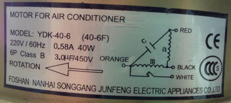
53 Common Wearing Parts 2.2 Fan Motor VHRA-18/48AN1DC/INB Photo 47

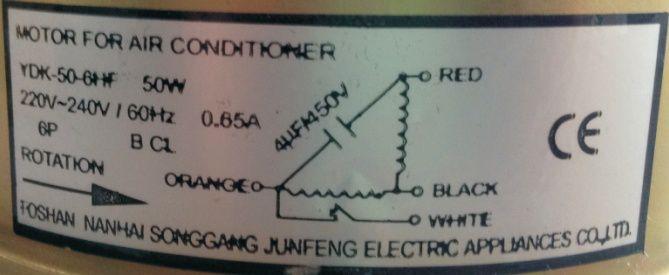
54 Common Wearing Parts VHRA-24AN1DC/INB Photo 48

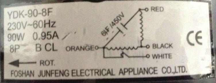
55 Common Wearing Parts VHRA-36AN1DC/INB Photo 49

56 Common Wearing Parts 2.3 Filter Capacitor VHRA-18AN1DC/INB Photo 50


57 Common Wearing Parts 2.4 Fan motor capacitor VHRA-18/48AN1DC/INB Photo VHRA-24AN1DC/INB Photo 51

58 Common Wearing Parts VHRA-36AN1DC/INB Photo 52
59 Comparison Table Part 5 Comparison Table 1. Wired Controller Function Operating Instructions Error Codes and Analysis Pressure Refrigerant Loop Temperature Control Table R410 Table Sensors Resistance Table Compressor Exhaust Temperature Sensor Resistance Ambient/Indoor/Outdoor Pipe Sensor Resistance

60 Comparison Table 1. Wired Controller 1.1 Function FUNCTION SETTING COOLING COMPRESSOR STATUS HEATING LOCK OUTDOOR UNIT FAN MOTOR STATUS ELECTRIC HEATING ELEMENT STATUS WATER TANK TIMER ON CLOCK/TIMER/HOUR-MINUTES TIMER OFF TEMPERATURE/FUNCTIONAL DATA WATER TANK HEATING Centigrade/Fahrenheit 54
61 Comparison Table 1.2 Operating Instructions 1: OPERATION: When displayed on panel, you could press ON/OFF button to unlock. 1.1: MODE button: Press this button could select Cooling mode or Heating mode; 1.2: ON/OFF button: Press to turn on or turn off the unit; If press till beep sound, to lock the wire controller, beep sound, to unlock the wire controller. if press again till 1.3: CLOCK button: 1.3.1Clock setting: Press CLOCK button till flashing, Minutes digit flashing, using UP DOWN button to set minute; press CLOCK button again, Hour digit flashing, using UP CLOCK button again or leave it for about 10 seconds, setting is saved automatically; DOWN button to set hour; after setting, press 1.3.2TIMER ON/OFF: System could be set for TIMER ON and TIMER OFF within 24hrs,setting unit by 1 minute. A. TIMER ON SETTING:When the system under OFF status,press CLOCK button into TIME ON,use UP DOWN button to choose time you want,and use CLOCK button to shift between Hour and Minute on the display.after setting press CLOCK button again or wait for 5 seconds for confirmation,time ON on the panel is on.if you want to cancel setting,just press ON/OFF button again. B. TIMER OFF SETTING:When the system under ON/Operation status,press CLOCK button,use UP DOWN button to choose time you want,and use CLOCK button to shift between Hour and Minute on the display.after setting press CLOCK button again or wait for 5 seconds for confirmation,time OFF on the panel is on.if you want to cancel setting,just press ON/OFF button again. 1.4: SET button : Press to set up or modify system parameters,shift between P01 P12, then using UP DOWN button to set-up or change data; after setting,press SET button again for saving: Press UP DOWN buttons together till beep sound,the whole system be recovered to the factory default setting. 1.5: UP DOWN buttons 1.5.1Press UP DOWN buttons together till beep sound,the whole system be recovered to the factory default setting Press UP DOWN buttons to select or adjust all kinds of data. 55
62 Comparison Table Code Setting mode Setting Data Range P01 Hot water temperature , Default:113 P02 Cold water temperature 41-95, Default:50 P03 P04 Water temperature difference for compressor start between water tank temp. & Hot water temp. 38 ~59, Default: 41 ON/OFF Mode or Constant Water Temperature(CWT) Mode 0: ON/OFF; 1: CWT; Default: 0 P05 P06 P07 P08 P09 P10 P11 P12 P13 Water temperature difference for compressor start under CWT Mode Delay time for Auxiliary Electric Heating Element starting under heating mode Auxiliary Electric Heating Element starting temperature Outdoor Ambient temperature for whole system shut-down Defrosting mode selection Defrosting starting by fan coil temperature (both for auto mode and manual mode) Defrosting cycle interval time (only for manual mode) Defrosting time (only for manual mode) Defrosting quit by fan coil temperature (both for auto mode and manual mode) 32 ~46, Default: min,Default:90min 68 ~131, Default: ~30, Default:-22 0: auto mode; 1: manual setting mode 5 ~35, Default:24 25~70min,Default:40 min 2~20 min,default:8 min 47 ~68, Default:53 P14 Water Pump on-off selection 0: on mode; 1: off mode 56
63 Comparison Table 1.3 Error Codes and Analysis ERROR CODE ERROR CODE INDICATION E01 Eeprom error(idu PCB/Wire controller) E02 The wster tank temperature sensor failure E05 Outdoor unit condenser temperature sensor failure E06 Outdoor unit ambient temperature sensor failure E07 Outdoor unit gas discharge temperature sensor failure E08 E09 E10 Signal communication between wire controller and indoor unit main PCB failure Signal communication between ouidoor onit main PCB and inverter modular modular board failure Boot failure (compressor protection disconnect;compressor top high temperature protection) E11 Outdoor unit overcurrent failure(current protection of outdoor unit) E12 Inverter modular board failure E13 Discharge gas temperature or compressor temperature overheat protection E15 Over current or low current protection E21 Water tank temperature is too low to protect 57
64 Comparison Table 2.Pressure Refrigerant Loop Temperature Control Table 2.1 R410 Table R410A REFRIGERANT PRESSURE TEMPERATURE TABLE Temperature(C ) Absolute Temperature(C ) Absolute Temperature(C ) Absolute Note: The conversion between absolute pressure and gauge pressure : the absolute pressure (MPa)-0.1MPa ( atmospheric pressure ) = gauge pressure (MPa). 58
65 Comparison Table 3. Sensors Resistance Table 3.1 Compressor Exhaust Temperature Sensor Resistance Unit: --KΩ (Compressor discharge temperature)55k t R(KΩ) AD t R(KΩ) AD t R(KΩ) AD t R(KΩ) AD B(25/50)=3950K %R(90 )=5KΩ %
66 Comparison Table 3.2 Ambient/Indoor/Outdoor Pipe Sensor Resistance Unit: --KΩ(Ambient/Indoor/Outdoor Pipe Sensor Resistance)10K t R(KΩ) AD t R(KΩ) AD t R(KΩ) AD t R(KΩ) AD
67 Appendix Part 6 Appendix 1. Piping Diagrams Indoor Units Outdoor Units Wiring Diagrams Indoor Units Outdoor Units
68 Appendix 1. Piping Diagrams 1.1 Indoor Units REFRIGERANT FLOW COOLING HEATING 62
69 Appendix 1.2 Outdoor Units REFRIGERANT FLOW COOLING HEATING 63
70 Appendix 2. Wiring Diagrams 2.1 Indoor Units VRHA-18/24/36/48AN1DC/INB 64
71 Appendix 2.2 Outdoor Units VRHA-18AN1DC/INB 65
72 Appendix VRHA-24/36AN1DC/INB 66
73 Appendix VRHA-48AN1DC/INB 67
SiBE04-808_C. Service Manual. Inverter Pair Wall Mounted Type G-Series. [Applied Models] Inverter Pair : Cooling Only Inverter Pair : Heat Pump
![SiBE04-808_C. Service Manual. Inverter Pair Wall Mounted Type G-Series. [Applied Models] Inverter Pair : Cooling Only Inverter Pair : Heat Pump](/thumbs/88/114609417.jpg "SiBE04-808_C. Service Manual. Inverter Pair Wall Mounted Type G-Series. [Applied Models] Inverter Pair : Cooling Only Inverter Pair : Heat Pump") Service Manual Inverter Pair Wall Mounted Type G-Series [Applied Models] Inverter Pair : Cooling Only Inverter Pair : Heat Pump Inverter Pair Wall Mounted Type G-Series Cooling Only Indoor Unit FTXS20G2V1B
Service Manual Inverter Pair Wall Mounted Type G-Series [Applied Models] Inverter Pair : Cooling Only Inverter Pair : Heat Pump Inverter Pair Wall Mounted Type G-Series Cooling Only Indoor Unit FTXS20G2V1B
SYSTEM Inverter Air Conditioners
 OPERATION MANUAL SYSTEM Inverter Air Conditioners MODEL Ceiling-mounted duct type low static pressure unit FXDQ07MVJU FXDQ09MVJU FXDQ12MVJU FXDQ18MVJU FXDQ24MVJU Read these instructions carefully before
DC INVERTER MULTI-SYSTEM AIR CONDITIONER
 TECHNICAL & SERVICE MANUAL OUTDOOR UNIT : CU-3KE19NBU CU-4KE24NBU CU-4KE31NBU DC INVERTER MULTI-SYSTEM AIR CONDITIONER Capacity at 0V 19,100 BTU/h,200 BTU/h 30,600 BTU/h Outdoor Model No. CU-3KE19NBU CU-4KE24NBU
Service Manual. Inverter Pair Floor / Ceiling Suspended Dual Type BA-Series. SiBE05-722_C
 Service Manual Inverter Pair Floor / Ceiling Suspended Dual Type BA-Series [Applied Models] Inverter Pair : Cooling Only Inverter Pair : Heat Pump Inverter Pair Floor / Ceiling Suspended Dual Type BA-Series
SERVICE MANUAL. Inverter Wall Mounted Single Split. MODELS Cooling Only. Heatpump SM-5WM-Y-NA-B1
 SERVICE MANUAL Inverter Wall Mounted Single Split MODELS Cooling Only FTKB09AXVJU FTKB12AXVJU FTKB18AXVJU FTKB24AXVJU FTKN09AXVJU FTKN12AXVJU FTKN18AXVJU FTKN24AXVJU Heatpump FTXB09AXVJU FTXB12AXVJU FTXB18AXVJU
SERVICE MANUAL. Wall Mounted Type ON/OFF T-Series HSU-07HUN103/R2-P WARNING. Haier Group Version V1 Date
 SERVICE MANUAL Wall Mounted Type ON/OFF T-Series Model No.1U07OR4EAA HSU-07HUN103/R2-P WARNING This service information is designed for experienced repair technicians only and is not designed for use by
SYSTEM Inverter Air Conditioners
 OPERATION MANUAL SYSTEM Inverter Air Conditioners MODELS Floor standing type and Concealed floor standing type FXLQ12MVJU FXLQ18MVJU FXLQ24MVJU FXNQ12MVJU FXNQ18MVJU FXNQ24MVJU Carefully read this operation
SiBE041010EA. Service Manual. Inverter Pair Wall Mounted Type J-Series. [Applied Models] Inverter Pair : Heat Pump
![SiBE041010EA. Service Manual. Inverter Pair Wall Mounted Type J-Series. [Applied Models] Inverter Pair : Heat Pump](/thumbs/88/115408421.jpg "SiBE041010EA. Service Manual. Inverter Pair Wall Mounted Type J-Series. [Applied Models] Inverter Pair : Heat Pump") Service Manual Inverter Pair Wall Mounted Type J-Series [Applied Models] Inverter Pair : Heat Pump Inverter Pair Wall Mounted Type J-Series Heat Pump Indoor Unit FTX20JV1B FTX25JV1B FTX35JV1B FTX20J2V1B
Service Manual Inverter Pair Wall Mounted Type J-Series [Applied Models] Inverter Pair : Heat Pump Inverter Pair Wall Mounted Type J-Series Heat Pump Indoor Unit FTX20JV1B FTX25JV1B FTX35JV1B FTX20J2V1B
SYSTEM Inverter Air Conditioners
 OPERATION MANUAL SYSTEM Inverter Air Conditioners MODELS Ceiling-mounted Cassette type (Multi flow model) FXFQ12MVJU FXFQ18MVJU FXFQ24MVJU FXFQ30MVJU FXFQ36MVJU Read these instructions carefully before
SiUS04-924_A. Service Manual. Inverter Pair Wall Mounted Type H-Series. [Applied Models] Inverter Pair : Cooling Only Inverter Pair : Heat Pump
![SiUS04-924_A. Service Manual. Inverter Pair Wall Mounted Type H-Series. [Applied Models] Inverter Pair : Cooling Only Inverter Pair : Heat Pump](/thumbs/71/65602543.jpg "SiUS04-924_A. Service Manual. Inverter Pair Wall Mounted Type H-Series. [Applied Models] Inverter Pair : Cooling Only Inverter Pair : Heat Pump") Service Manual Inverter Pair Wall Mounted Type H-Series [Applied Models] Inverter Pair : Cooling Only Inverter Pair : Heat Pump Inverter Pair Wall Mounted Type H-Series Cooling Only Indoor Unit FTXS30HVJU
Service Manual Inverter Pair Wall Mounted Type H-Series [Applied Models] Inverter Pair : Cooling Only Inverter Pair : Heat Pump Inverter Pair Wall Mounted Type H-Series Cooling Only Indoor Unit FTXS30HVJU
OPERATION MANUAL. SYSTEM Inverter Air Conditioners FXSQ36MVJU FXMQ36MVJU FXSQ48MVJU. MODELS Ceiling-mounted Duct type. Ceiling-mounted Built-in type
 OPERATION MANUAL SYSTEM Inverter Air Conditioners MODELS Ceiling-mounted Duct type FXMQ30MVJU FXMQ36MVJU FXMQ48MVJU Ceiling-mounted Built-in type FXSQ12MVJU FXSQ18MVJU FXSQ24MVJU FXSQ30MVJU FXSQ36MVJU
15,000 BTU Portable Air Conditioner
 Instruction Manual 15,000 BTU Portable Air Conditioner Model: HYAC15 READ AND SAVE THESE INSTRUCTIONS Please read and follow the instructions in this user manual even if you feel you are familiar with
Multi-Zone Technical Overview
 Multi-Zone Technical Overview Table of Contents Introduction... 2-11 Nomenclature... 2 Specifications...3-5 Safety Overview...6-7 Functions & Controls... 8-11 Outdoor Unit Technical Overview... 13-33 Components...
INSTALLATION AND USER MANUAL
 INSTALLATION AND USER MANUAL Thank you for choosing inverter heat pump. This manual provides you necessary information for optimal use and maintenance, please read it carefully and keep it for subsequent
KSD-35 DR11 KUE-35 DVN11
 FLOOR-STANDING TYPE AIR CONDITIONER Owner s Manual Floor-Standing Type KSD-35 DR11 KUE-35 DVN11 IMPORTANT NOTE: Read this manual carefully before installing or operating your new air conditioning unit.
INSTALLATION AND USER MANUAL
 INSTALLATION AND USER MANUAL t Thank you for choosing Aqua inverter heat pump. This manual provides you necessary information for optimal use and maintenance, please read it carefully and keep it for subsequent
SERVICE MANUAL. Wall Mounted Type DC Inverter WARNING. Haier Group Version V1 Date
 SERVICE MANUAL Wall Mounted Type DC Inverter Model No.1U18EE8ERA WARNING This service information is designed for experienced repair technicians only and is not designed for use by the general public.
DUCTED AIR CONDITIONER. Owner s Manual. KD Series KD24. Kaden Owner s Manual 1
 DUCTED AIR CONDITIONER Owner s Manual KD Series KD24 Kaden Owner s Manual 1 Table of Contents 1. Safety Precautions 4 2. Indoor Unit Parts and Major Functions 6 3. Care and Maintenance 8 4. Troubleshooting
SILENT 12 PORTABLE AIR CONDITIONER USER MANUAL
 SILENT 12 PORTABLE AIR CONDITIONER USER MANUAL Thank you for choosing ElectriQ Please read this user manual before using this innovative Air Conditioner and keep it safe for future reference. Visit our
AUTO COOL DRY FAN SPEED AIR SWING OFF ON TIMER TIMER OFF/ON FAN SPEED MODE TEMP AIR SWING TIMER ON SET OFF CANCEL AC RC SET CHECK CLOCK RESET
 AUTO COOL DRY MODE TIMER ON OFF TIMER OFF/ON TEMP ON TIMER FAN SPEED AIR SWING SET 1 2 3 FAN SPEED AIR SWING OFF CANCEL AC RC SET CHECK CLOCK RESET Order No: PAPAMY1611008CE Indoor Unit CS-MPS9SKH CS-MPS12SKH
SiE Service Manual. Split System Air Conditioners SkyAir R-407C Super Inverter 70 D Series. [Applied Models] SkyAir : Inverter Heat Pump
![SiE Service Manual. Split System Air Conditioners SkyAir R-407C Super Inverter 70 D Series. [Applied Models] SkyAir : Inverter Heat Pump](/thumbs/85/91924488.jpg "SiE Service Manual. Split System Air Conditioners SkyAir R-407C Super Inverter 70 D Series. [Applied Models] SkyAir : Inverter Heat Pump") Service Manual Split System Air Conditioners SkyAir R-407C Super Inverter 70 D Series [Applied Models] SkyAir : Inverter Heat Pump Split-System Air Conditioners SkyAir Super Inverter 70 D Series 1. Introduction...
Service Manual Split System Air Conditioners SkyAir R-407C Super Inverter 70 D Series [Applied Models] SkyAir : Inverter Heat Pump Split-System Air Conditioners SkyAir Super Inverter 70 D Series 1. Introduction...
CLIM9000CE PORTABLE AIR CONDITIONER USER MANUAL
 CLIM9000CE PORTABLE AIR CONDITIONER USER MANUAL Please read this user manual before using this innovative Air Conditioner and keep it safe for future reference. SAFETY INSTRUCTIONS Important! Carefully
3 In 1 AIR CONDITIONER with REMOTE CONTROL MODEL NO: CA9000 PART No: OPERATION & MAINTENANCE INSTRUCTIONS
 3 In 1 AIR CONDITIONER with REMOTE CONTROL MODEL NO: CA9000 PART No: 32305600 OPERATION & MAINTENANCE INSTRUCTIONS 0304 Parts List Item Part No Description Qty 1 FT900001 Top Cover 1 2 FT900002 Filter
SERVICE MANUAL. Wall Mounted Type DC Inverter WARNING. Haier Group Version V1 Date
 SERVICE MANUAL Wall Mounted Type DC Inverter Model No.U25BEFFRA WARNING This service information is designed for experienced repair technicians only and is not designed for use by the general public. It
Owner s Manual Super-Slim Four-Way Cassette
 CASSETTE- TYPE AIR CONDITIONER Owner s Manual Super-Slim Four-Way Cassette IMPORTANT NOTE: Read this manual carefully before installing or operating your new air conditioning unit. Make sure to save this
HNC-120BE-L/R-B HNC-150BE-L/R-B HNC-180BE-L/R-B HNC-210BE-L/R-B COUNTER SHOWCASE MODEL SERVICE MANUAL HOSHIZAKI
 NO. S051-800 ISSUED: MAR. 26, 2010 REVISED: HOSHIZAKI COUNTER SHOWCASE MODEL HNC-120BE-L/R-B HNC-150BE-L/R-B HNC-180BE-L/R-B HNC-210BE-L/R-B SERVICE MANUAL IMPORTANT This manual should be read carefully
COMPACT PORTABLE AIR CONDITIONER USER MANUAL
 COMPACT PORTABLE AIR CONDITIONER USER MANUAL Thank you for choosing ElectriQ Please read this user manual before using this innovative Air Conditioner and keep it safe for future reference. Visit our page
Bosch Split-Type Ductless Air Conditioner / Heat Pump
 Bosch Split-Type Ductless Air Conditioner / Heat Pump Climate 5000 AA Series User Manual 2 Bosch Split Type Ductless Air Conditioner / Heat Pump User Manual Data subject to change 01.2017 Bosch Thermotechnology
SERVICE MANUAL. Model No. HSU09VHJ(DB) Wall mounted Type DC Inverter EA-Series WARNING. Haier Group. Order No.AC1101S020V0
 Wall mounted Type DC Inverter EA-Series WARNING. Haier Group. Order No.AC1101S020V0") SERVICE MANUAL Order No.AC0S020V0 Wall mounted Type DC Inverter EA-Series Model No. HSU09VHJ(DB) WARNING This service information is designed for experienced repair technicians only and is not designed
SERVICE MANUAL Order No.AC0S020V0 Wall mounted Type DC Inverter EA-Series Model No. HSU09VHJ(DB) WARNING This service information is designed for experienced repair technicians only and is not designed
Owner s Manual. Middle Static Pressure Duct Type MEU-18MPH2 MEU-24MPH2 MEU-36MPL2 MEU-48MPL2 MIDDLE STATIC PRESSURE DUCT TYPE AIR CONDITIONER
 MIDDLE STATIC PRESSURE DUCT TYPE AIR CONDITIONER Owner s Manual Middle Static Pressure Duct Type MEU-18MPH2 MEU-24MPH2 MEU-36MPL2 MEU-48MPL2 IMPORTANT NOTE: Read this manual carefully before installing
Ductless Split Air Conditioner
 Ductless Split Air Conditioner Service Manual Indoor HSU09VHG(DB)-W HSUVHG(DB)-W HSU8VHH(DB)-W HSUVHG(DB)-W Outdoor HSU09VHG(DB)-G HSUVHG(DB)-G HSU8VHH(DB)-G HSUVHG(DB)-G Design may vary by model number.
Owner s Manual CS
 Owner s Manual IMPORTANT NOTE: Read this manual carefully before installing or operating your new air conditioning unit. Make sure to save this manual for future reference. CS78421-548-754 Table of Contents
THROUGH-WALL AIR-TO-AIR HEAT PUMP AND AIR CONDITIONER. Instruction Manual. Model AMB-12H
 THROUGH-WALL AIR-TO-AIR HEAT PUMP AND AIR CONDITIONER Instruction Manual Model AMB-12H PLEASE READ THIS INSTRUCTION MANUAL CAREFULLY BEFORE USING THIS UNIT. Table of Contents 1. SAFETY WARNINGS 2 2. CONSTRUCTION...
NEXXOS INVERTER USER MANUAL
 NEXXOS INVERTER USER MANUAL NIN412C2V32 NIN415C2V32 NIN520C2V32 NIN725C2V32 INVERTER MINI SPLIT SYSTEM WARNING The information contained in the manual is intended for use by a qualified service technician
SiUS091601E Inverter Pair Wall Mounted Type FTX-N Series Floor Standing Type FVXS-N Series [Applied Models] Inverter Pair : Heat Pump
![SiUS091601E Inverter Pair Wall Mounted Type FTX-N Series Floor Standing Type FVXS-N Series [Applied Models] Inverter Pair : Heat Pump](/thumbs/71/66157661.jpg "SiUS091601E Inverter Pair Wall Mounted Type FTX-N Series Floor Standing Type FVXS-N Series [Applied Models] Inverter Pair : Heat Pump") Service Manual Inverter Pair Wall Mounted Type FTX-N Series Floor Standing Type FVXS-N Series [Applied Models] Inverter Pair : Heat Pump Inverter Pair Wall Mounted Type FTX-N Series Floor Standing Type
Service Manual Inverter Pair Wall Mounted Type FTX-N Series Floor Standing Type FVXS-N Series [Applied Models] Inverter Pair : Heat Pump Inverter Pair Wall Mounted Type FTX-N Series Floor Standing Type
Service Manual & Installation Manual
 GE Consumer & Industrial Appliances Service Manual & Installation Manual Split System Air Conditioner Model numbers: GE AIR C18 GE AIR C24 GE AIR C34 GE AIR C41 1 Introduction and Features Model Remarks
Service Manual & Installation Manual
 GE Consumer & Industrial Appliances Service Manual & Installation Manual Split System Air Conditioner Model numbers: GE AIR F24 GE AIR F34 GE AIR F41 1 2 3 Introduction and Features Model Remarks GE AIR
Owner s Manual SPLIT-TYPE ROOM AIR CONDITIONER
 Owner s Manual SPLIT-TYPE ROOM AIR CONDITIONER IMPORTANT NOTE: Read this manual carefully before installing or operating your new air conditioning unit. Make sure to save this manual for future reference.
Utopian Split A/C. Thank you for purchasing this quality Split A/C system!
 Utopian Split A/C Thank you for purchasing this quality Split A/C system! Please read through this manual completely, and keep it in case you need to reference the information in the future. Any operation
DAIKIN ROOM AIR CONDITIONER. Operation Manual
 DAIKIN ROOM AIR CONDITIONER Operation Manual FDXM25F2V1B FDXM50F2V1B FDXM35F2V1B FDXM60F2V1B CONTENTS READ BEFORE OPERATION Safety precautions... 2 Names of parts... 4 CARE Care and Cleaning... 6 TROUBLE
Inverter Swimming Pool Heat Pump
 P Inverter Swimming Pool Heat Pump Content I. Application... 2 II. Features... 2 III. Technical Parameter... 3 IV. Dimension... 4 V. Installation instruction... 5 VI. Operation instruction... 9 VII. Testing...
SPLIT TYPE ROOM AIR CONDITIONER CEILING TYPE (60Hz)
") SPLIT TYPE ROOM AIR CONDITIONER CEILING TYPE (60Hz) Indoor unit MS6YF Outdoor unit MR6YF CONTENTS SPECIFICATIONS... OUTLINE AND DIMENSIONS... REFRIGERANT SYSTEM DIAGRAM.... CIRCUIT DIAGRAM... INDOOR PCB
SPLIT TYPE ROOM AIR CONDITIONER CEILING TYPE (60Hz) Indoor unit MS6YF Outdoor unit MR6YF CONTENTS SPECIFICATIONS... OUTLINE AND DIMENSIONS... REFRIGERANT SYSTEM DIAGRAM.... CIRCUIT DIAGRAM... INDOOR PCB
Inverter Pair Wall Mounted Type H-Series
 Inverter Pair Wall Mounted Type H-Series [Applied Models] Inverter Pair : Heat Pump Inverter Pair H-Series Heat Pump Indoor Units FTXS30HVJU FTXS36HVJU Outdoor Units RXS30HVJU RXS36HVJU Inverter Pair H-Series
USER MANUAL SILENT16 PORTABLE AIR CONDITIONER
 USER MANUAL SILENT16 PORTABLE AIR CONDITIONER Thank you for choosing electriq Please read this user manual before using this innovative Air Conditioner and keep it safe for future reference. Visit our
Chiltrix 5.1 Thin DC - Inverter Water Fan Coil Unit Floor, Wall or Ceiling Universal Mount Manual
 Chiltrix 5.1 Thin DC - Inverter Water Fan Coil Unit Floor, Wall or Ceiling Universal Mount Manual Version 1.5 1 CONTENTS CHAPTER 1 GENERAL INTRODUCTION...3 1. Preface... 3 2. Product Introduction... 3
Ductless Split Air Conditioner
 Ductless Split Air Conditioner Service Manual Indoor AW09ESVHA AWESVHA AW8ESVHA AWESVHA Outdoor U09ESVHA UESVHA U8ESVHA UESVHA Design may vary by model number. Please read this manual before using the
OWNER S MANUAL KPD-105 DTN11 KPD-140 DVN11 KPD-140 DTN11 KPD-160 DTN11 KPD-52 DVR11
 OWNER S MANUAL A6 Duct KPD-35 DVN11 KPD-52 DVN11 KPD-71 DVN11 KPD-90 DVN11 KPD-105 DVN11 KPD-105 DTN11 KPD-140 DVN11 KPD-140 DTN11 KPD-160 DTN11 KPD-52 DVR11 KPD-71 DVR11 KPD-105 DVR11 KPD-105 DTR11 KPD-140
Multi Inverter Air Conditioning Condensing Units - Summary
 Multi Inverter Air Conditioning Condensing Units - Summary Model Description Nominal Max of Cooling Inverter No. Heating of (kw) Fan Condensing (kw) Coils Unit ECO18MS2 Twin Multi Inverter 5kW 5.2 6.1
CEILING type (60Hz) SPLIT TYPE ROOM AIR CONDITIONER CONTENTS. Models
 SPLIT TYPE ROOM AIR CONDITIONER CONTENTS. Models") SPLIT TYPE ROOM AIR CONDITIONER CEILING type (60Hz) Models Indoor unit ABU6RSLX Outdoor unit AOU6RLX CONTENTS SPECIFICATIONS....................... OUTLINE AND DIMENSIONS............. REFRIGERANT SYSTEM
SPLIT TYPE ROOM AIR CONDITIONER CEILING type (60Hz) Models Indoor unit ABU6RSLX Outdoor unit AOU6RLX CONTENTS SPECIFICATIONS....................... OUTLINE AND DIMENSIONS............. REFRIGERANT SYSTEM
DC INVERTER MULTI-SYSTEM AIR CONDITIONER
 TECHNICAL & SERVICE MANUAL OUTDOOR UNIT : CLM97 CLM7 CLM7 FILE NO. Destination: North America DC INVERTER MULTI-SYSTEM AIR CONDITIONER Capacity at 0V 9,700 BTU/h,00 BTU/h 0,600 BTU/h Outdoor Model No.
Owner s Manual. Fairwind Series All Model Numbers SPLIT-TYPE ROOM AIR CONDITIONER CS
 SPLIT-TYPE ROOM AIR CONDITIONER Owner s Manual Fairwind Series All Model Numbers IMPORTANT NOTE: Read this manual carefully before installing or operating your new air conditioning unit. Make sure to save
Table of Contents SAFETY FIRST. Owner s Manual. Safety Precautions Unit Specifications and Features Manual Operation (Without Remote)...
...") User Manual Table of Contents Owner s Manual 0 1 Safety Precautions...04 Unit Specifications and Features...06 SAFETY FIRST 2 Manual Operation (Without Remote)...11 3 Care and Maintenance...12 4 Troubleshooting...14
User Manual Table of Contents Owner s Manual 0 1 Safety Precautions...04 Unit Specifications and Features...06 SAFETY FIRST 2 Manual Operation (Without Remote)...11 3 Care and Maintenance...12 4 Troubleshooting...14
SiBE041525F. Service Manual. Inverter Pair Wall Mounted Type FTX/ATX-K Series. [Applicable Models] Inverter Pair: Heat Pump
![SiBE041525F. Service Manual. Inverter Pair Wall Mounted Type FTX/ATX-K Series. [Applicable Models] Inverter Pair: Heat Pump](/thumbs/92/110790777.jpg "SiBE041525F. Service Manual. Inverter Pair Wall Mounted Type FTX/ATX-K Series. [Applicable Models] Inverter Pair: Heat Pump") Service Manual Inverter Pair Wall Mounted Type FTX/ATX-K Series [Applicable Models] Inverter Pair: Heat Pump Inverter Pair Wall Mounted Type FTX/ATX-K Series Heat Pump Indoor Unit FTX20K(2)V1B FTX50K(M/2)V1B
Service Manual Inverter Pair Wall Mounted Type FTX/ATX-K Series [Applicable Models] Inverter Pair: Heat Pump Inverter Pair Wall Mounted Type FTX/ATX-K Series Heat Pump Indoor Unit FTX20K(2)V1B FTX50K(M/2)V1B
DEHUMIDIFIER MODELS: SD-31E / SD-41E / SD-61E / SD-71E INSTRUCTION MANUAL
 DEHUMIDIFIER MODELS: SD-31E / SD-41E / SD-61E / SD-71E INSTRUCTION MANUAL Please read these instructions thoroughly and keep it in a safe place for future reference. CONTENTS SAFETY PRECAUTUIONS... 2 ELECTRICAL
Portable Air Conditioner USER MANUAL
 AC12 AC12HP Portable Air Conditioner USER MANUAL Thank you for choosing this innovative Amcor air conditioner. We suggest that you keep this manual in a safe place for future reference. It describes the
General safety precautions English
 English A min (m 2 ) 550 530 540 510 520 490 500 470 480 450 460 430 440 410 420 390 400 370 380 350 360 330 340 310 320 290 300 270 280 250 260 230 240 210 220 190 200 170 180 150 160 130 140 110 120
General safety precautions English
 English A min (m 2 ) 550 530 540 510 520 490 500 470 480 450 460 430 440 410 420 390 400 370 380 350 360 330 340 310 320 290 300 270 280 250 260 230 240 210 220 190 200 170 180 150 160 130 140 110 120
Installation Instructions
 40MAQ High Wall Ductless Split System Sizes 09 to 36 Installation Instructions NOTE: Read the entire instruction manual before starting the installation TABLE OF CONTENTS PAGE SAFETY CONSIDERATIONS 2 PARTS
AIR CONDITIONER. Please read this owner, s manual carefully before using the air conditioner, and keep this manual for the future reference.
 Owner, s Manual AIR CONDITIONER Please read this owner, s manual carefully before using the air conditioner, and keep this manual for the future reference. CONTENTS 1. Safety Precaution-------------------------------------------------------------------------------1
USER MANUAL. Safety Precautions. Unit Specifications and Features. Operating Instructions. Installation Instructions.
 Safety Precautions Unit Specifications and Features Operating Instructions Installation Instructions Care and Cleaning Troubleshooting Tips USER MANUAL Dehumidifier TDDP7011ES2 Warning notices: Before
Warning: 230V / 1ph / 50Hz V / 3ph / 50Hz. Remarks: Make sure that you have enough power. (See page 15 Cable table)
") 1 2 Warning: - Do not place your hand or any other objects into the air outlet and fan. It could damage the heat pump and cause injuries; - In case of any abnormality with the heat pump, cut off the power
1 2 Warning: - Do not place your hand or any other objects into the air outlet and fan. It could damage the heat pump and cause injuries; - In case of any abnormality with the heat pump, cut off the power
YC ON-OFF SERIES. Service Manual
 YC ON-OFF SERIES Service Manual CONTENTS 1. Precaution... 3 1.1 Safety Precaution... 3 1.2 Warning... 3 2. Model Lists... 6 3. Dimension... 7 3.1 Indoor Unit... 7 3.2 Outdoor Unit... 11 4. Refrigerant
SiUS181631EA. Service Manual. Multi-Split Type Air Conditioners RMXS-L Series. [Applied Models] Inverter Multi : Heat Pump
![SiUS181631EA. Service Manual. Multi-Split Type Air Conditioners RMXS-L Series. [Applied Models] Inverter Multi : Heat Pump](/thumbs/86/94613913.jpg "SiUS181631EA. Service Manual. Multi-Split Type Air Conditioners RMXS-L Series. [Applied Models] Inverter Multi : Heat Pump") Service Manual Multi-Split Type Air Conditioners RMXS-L Series [Applied Models] Inverter Multi : Heat Pump Multi-Split Type Air Conditioners RMXS-L Series Heat Pump Outdoor Unit RMXS48LVJU Branch Provider
Service Manual Multi-Split Type Air Conditioners RMXS-L Series [Applied Models] Inverter Multi : Heat Pump Multi-Split Type Air Conditioners RMXS-L Series Heat Pump Outdoor Unit RMXS48LVJU Branch Provider
Part 5. Troubleshooting. 1. Normal Air Conditioner Phenomenon Air Conditioner Protection in Common
 Part 5 1. Normal Air Conditioner Phenomenon... 1611 2. Air Conditioner Protection in Common... 1611 3. Malfunction Code and... 162 160 1. Normal Air Conditioner Phenomenon 1.1 When outdoor unit appears
Inverter Split-type Room Air Conditioner
 OWNER S MANUAL Inverter Split-type Room Air Conditioner Please read the operating instructions and safety precautions carefully and thoroughly before installing and operating your room air conditioner.
EC300W. Evaporative Air Cooler OWNERS MANUAL. Read and save these instructions.
 EC300W Evaporative Air Cooler OWNERS MANUAL Read and save these instructions. 2 Trust should be earned and we will earn yours. Customer happiness is the focus of our business. From the factory to the warehouse,
INSTALLATION AND USER MANUAL
 INSTALLATION AND USER MANUAL Thank you for choosing our product and trusting our company. This manual is to provide you with necessary information for optimal use and maintenance, please read carefully
OWNER S MANUAL. AIR CONDITIONER (SPLIT TYPE) For general public use Indoor unit RAS-10, 13, 18, 24, 30BKS-HK
 For general public use Indoor unit RAS-10, 13, 18, 24, 30BKS-HK") OWNER S MANUAL ENGLISH AIR CONDITIONER (SPLIT TYPE) For general public use Indoor unit RAS-0,, 8, 24, 0BKS-HK Outdoor unit RAS-0,, 8, 24, 0BAS-HK 065560 065560_EN.indd 9/0/2558 BE 5:07 PRECAUTIONS FOR
OWNER S MANUAL ENGLISH AIR CONDITIONER (SPLIT TYPE) For general public use Indoor unit RAS-0,, 8, 24, 0BKS-HK Outdoor unit RAS-0,, 8, 24, 0BAS-HK 065560 065560_EN.indd 9/0/2558 BE 5:07 PRECAUTIONS FOR
SiBE041433E. Service Manual. Inverter Pair Wall Mounted Type FTXJ-L Series. [Applied Models] Inverter Pair : Heat Pump
![SiBE041433E. Service Manual. Inverter Pair Wall Mounted Type FTXJ-L Series. [Applied Models] Inverter Pair : Heat Pump](/thumbs/87/96681756.jpg "SiBE041433E. Service Manual. Inverter Pair Wall Mounted Type FTXJ-L Series. [Applied Models] Inverter Pair : Heat Pump") Service Manual Inverter Pair Wall Mounted Type FTXJ-L Series [Applied Models] Inverter Pair : Heat Pump Inverter Pair Wall Mounted Type FTXJ-L Series Heat Pump Indoor Unit FTXJ20LV1BW FTXJ20LV1BS FTXJ25LV1BW
Service Manual Inverter Pair Wall Mounted Type FTXJ-L Series [Applied Models] Inverter Pair : Heat Pump Inverter Pair Wall Mounted Type FTXJ-L Series Heat Pump Indoor Unit FTXJ20LV1BW FTXJ20LV1BS FTXJ25LV1BW
Installation Instructions
 0908HN50 Lossnay Energy Recovery Ventilator Model: LGH-50RSDC-E (0-0V 50Hz) Installation Instructions (For use by dealer/contractor) Contents Safety precautions... Outline drawings... Standard installation
SERVICE MANUAL 42QHF009DS* 42QHF012DS* 42QHF018DS* 42QHF022DS* 38QUS009DS* 38QUS012DS* 38QUS018DS* 38QUS022DS* Indoor unit.
 SERVICE MANUAL Indoor unit Outdoor unit 42QHF009DS* 42QHF012DS* 42QHF018DS* 42QHF022DS* 38QUS009DS* 38QUS012DS* 38QUS018DS* 38QUS022DS* INDEX PART1 GENERAL INFORMATION PART2 ELECTRICAL DIAGRAM PART3 TROUBLE
GDDEM10 DEHUMIDIFIER
 GDDEM10 DEHUMIDIFIER SOCIABLE REMARK When using this dehumidifier in the European countries, the following information must be followed: DISPOSAL: Do not dispose this product as unsorted municipal waste.
Instruction Manual. Portable Air Conditioner
 Instruction Manual Portable Air Conditioner Model: WA-9010E It is important that you read these instructions before using your portable air conditioner and we strongly recommend that you keep them in a
Portable Air Conditioner
 AC-12200E AC-12200H Portable Air Conditioner OWNER S MANUAL v1.0 Read and save these instructions. 2 A Name You Can Trust Trust should be earned and we will earn yours. Customer happiness is the focus
AC-12200E Portable Air Conditioner
 AC-12200E Portable Air Conditioner OWNERS MANUAL Read and save these instructions. A Name You Can Trust Trust has to be earned and we will earn yours. Customer happiness is the focus of our business. 2
Technical Support Division GD CHIGO HEATING & VENTILATION EQUIPMENT CO., LTD.
 Technical Support Division 2017-4-25 New CMV System - Floor ceiling Indoor Unit 1 1. External appearance 2. Nomenclature 3. Specifications 4. Dimensions 5. Service space 6. Piping diagram 7. Wiring diagram
MARINE SELF-CONTAINED DIRECT EXPANSION AIR CONDITIONING SYSTEMS
 MARINE SELF-CONTAINED DIRECT EXPANSION AIR CONDITIONING SYSTEMS Installation Manual Models : SC4.2 (Z) SC06 (Z) SC10 (Z) SC12 (Z) SC17 (Z) 2 Introduction Safety Precautions Technical Parameters Outline
KSIA SERIES SPLIT TYPE ROOM AIR CONDITIONER. For Split Wall Mounted Series R410a Inverter Model Type For F
 KSIA SERIES ro le oo SPLIT TYPE ROOM AIR CONDITIONER For Split Wall Mounted Series R410a Inverter Model Type For F KSIA009-H216-I / KSIA009-H216-O KSIA012-H216-I / KSIA012-H216-O KSIA018-H216-I / KSIA018-H216-O
SPLIT TYPE ROOM AIR CONDITIONER FLOOR CONSOLE / UNDER CEILING DUAL TYPE
 SPLIT TYPE ROOM AIR CONDITIONER FLOOR CONSOLE / UNDER CEILING DUAL TYPE Indoor unit ABYF8LAT ABYF8LAT ABYF8LAT ABYF8LAT ABYF8LBT ABYF8LBT ABYFLAT ABYFLAT ABYFLAT ABYFLAT ABYFLBT ABYFLBT Outdoor unit AOYA8LACL
CPG*CA CPG*CD CGC*CA CGC*CD CIM*CA CIM*CD CPP*CA CPP*CD
 CPG*CA CPG*CD CGC*CA CGC*CD CIM*CA CIM*CD CPP*CA CPP*CD eair LLC 12201 N.W. 107 Avenue, Medley, FL 33178 www.comfortstarusa.com Table of Contents Owner s Manual 0 1 Safety Precautions...04 Unit Specifications
SERVICE MANUAL K LIGHT COMMERCIAL
 SERVICE MANUAL 36 48 60K LIGHT COMMERCIAL Cassette indoor unit Under-ceiling indoor unit Ducted indoor unit 42QTD036DS* 42QTD048DS* 42QTD060DS* 42QZL036DS* 42QZL048DS* 42QZL060DS* 42QSM036DS* 42QSM048DS*
DC INVERTER SPLIT SYSTEM AIR CONDITIONER
 AIR CONDITIONER TECHNICAL & SERVICE MANUAL CS-KE30NKU + CU-KE30NKU CS-KE36NKU + CU-KE36NKU DC INVERTER SPLIT SYSTEM AIR CONDITIONER Indoor Model No. CS-KE30NKU CS-KE36NKU Product Code No. 1 852 360 88
Welcome. Important Safeguards. Please read the Manual carefully before operating the machine ELECTRICAL CONNECTIONS:
 Welcome Thank you for purchasing the new Portable Air Condition SY-AC1200. Read this instruction booklet carefully in order to benefit fully from this product. Store the user manual in a safe place for
SERVICE MANUAL. No. OBH747 REVISED EDITION-A. Models HFC
 Revision A: MUZ-HM09/12NA- U8, MUZ-HM09/12NA2- U8, MUZ-HM15/18NA- U1, MUZ-HM15/18NA2- U1 and MUZ-HM24NA2- U1 have been added. Please void OBH747. OUTDOOR INDOOR UNIT UNIT SERVICE MANUAL HFC utilized R410A.
DLCLRA. INSTALLATION INSTRUCTIONS Outdoor Unit Single Zone Ductless System Sizes 36 to 58 TABLE OF CONTENTS
 DLCLRA INSTALLATION INSTRUCTIONS Outdoor Unit Single Zone Ductless System Sizes 36 to 58 Fig. 1 - Size 36 TABLE OF CONTENTS PAGE SAFETY CONSIDERATIONS... 2 PARTS LIST... 3 SYSTEM REQUIREMENTS... 4 WIRING...
OPERATION MANUAL. System air conditioner
 OPERATION MANUAL System air conditioner MODEL REYQ72TTJU REYQ96TTJU REYQ120TTJU REYQ144TTJU REYQ168TTJU REYQ192TTJU REYQ216TTJU REYQ240TTJU REYQ264TTJU REYQ288TTJU REYQ312TTJU REYQ336TTJU REYQ360TTJU REYQ384TTJU
KSIM20912-H216 KSIM30912-H216 KSIM40912-H216
 SERVICE MANUAL KLIMAIRE AIRCONDITIONER KSIM DC INVERTER MULTI TYPE KSIM20912-H216 KSIM30912-H216 KSIM40912-H216 DC MULTI OUTDOOR UNITS CONTENTS 1. General information of Outdoor Units...3 2 Features...4
NOTE: All the illustrations in this manual are for explanation purposes only. Your air conditioner may be slightly different.
 RADS-51J RADS-61J Owner s Manual Room Air Conditioner with R-410A Heat Controller, Inc. 15 16 Contact an authorized service technician for repair or maintenance of this unit. Contact an authorized installer
Mobile Air Conditioner Use and Care Manual. Part Number: 048-GM-48265
 Mobile Air Conditioner Use and Care Manual Part Number: 048-GM-48265 Thank you very much for selecting this new model of Portable Air Conditioner, please read this Use and Care Manual carefully before
PORTABLE AIR CONDITIONER OWNER S MANUAL
 PORTABLE AIR CONDITIONER OWNER S MANUAL ASSEMBLY AND OPERATING INSTRUCTIONS MODELS: JHS-A018-10KR SKU#: 130004 JHS-A018-12KRH SKU#: 130005 JHS-A018-14KRH SKU#: 130009 WARNING: Read and follow all warnings
FLOOR CONSOLE / UNDER CEILING DUAL type (60Hz)
") SPLIT TYPE ROOM AIR CONDITIONER FLOOR CONSOLE / UNDER CEILING DUAL type (60Hz) Models Indoor unit MSYF Outdoor unit MRUYF CONTENTS SPECIFICATIONS... OUTLINE AND DIMENSIONS... REFRIGERANT SYSTEM DIAGRAM...
SPLIT TYPE ROOM AIR CONDITIONER FLOOR CONSOLE / UNDER CEILING DUAL type (60Hz) Models Indoor unit MSYF Outdoor unit MRUYF CONTENTS SPECIFICATIONS... OUTLINE AND DIMENSIONS... REFRIGERANT SYSTEM DIAGRAM...
DAIKIN ROOM AIR CONDITIONER. Operation Manual. English. Deutsch. Français. Nederlands. Español. Italiano. Ελληνικά. Portugues. Русский.
 DAIKIN ROOM AIR CONDITIONER Operation Manual FDXS25F2VEB FDXS60F2VEB FDXS35F2VEB FDXS50F2VEB English Deutsch Français Nederlands Español Italiano Ελληνικά Portugues Русский Türkçe CONTENTS READ BEFORE
TECHNICAL & SERVICE MANUAL WINDOW TYPE AIR CONDITIONER SA 183A FILE NO. SA 183A REFERENCE NO. SM Destination Australia SA-183A
 TECHNICAL & SERVICE MANUAL SA 183A FILE NO. WINDOW TYPE AIR CONDITIONER Model No. Product Code No. SA-183A 1 851 006 96 Destination Australia SA 183A REFERENCE NO. SM700514 IMPORTANT! Please Read Before
OPERATION MANUAL. System air conditioners FXAQ15AUV1B FXAQ20AUV1B FXAQ25AUV1B FXAQ32AUV1B FXAQ40AUV1B FXAQ50AUV1B FXAQ63AUV1B
 OPERATION MANUAL System air conditioners FXAQ15AUV1B FXAQ20AUV1B FXAQ25AUV1B FXAQ32AUV1B FXAQ40AUV1B FXAQ50AUV1B FXAQ63AUV1B Air inlet (top of main unit) Air filter (Under the panel) Name plate (Indoor
CASSETTE type INVERTER MULTI AIR CONDITIONER. Models AUY12LBAB AUY14LBAB AOY18LMAK2
 INVERTER MULTI AIR CONDITIONER CASSETTE type Models Indoor unit AUY12LBAB AUY14LBAB Outdoor unit AOY18LMAK2 CONTENTS SPECIFICATIONS..................... 1 OUTLINE AND DIMENSIONS........... 2 REFRIGERANT
FLOOR CONSOLE / UNDER CEILING DUAL type
 SPLIT TYPE ROOM AIR CONDITIONER FLOOR CONSOLE / UNDER CEILING DUAL type Models Indoor unit ABU8RULX ABURULX Outdoor unit AOU8RLX AOURLX CONTENTS SPECIFICATIONS... OUTLINE AND DIMENSIONS... REFRIGERANT
Portable Oxygen Monitor OX-07. (Type B) <No Gas alarm type> Operating Manual
 <No Gas alarm type> Operating Manual") PT0E-0922 Portable Oxygen Monitor OX-07 (Type B) Operating Manual Request for the Customers Read and understand this operating manual before using this gas monitor. Use it in accordance
PT0E-0922 Portable Oxygen Monitor OX-07 (Type B) Operating Manual Request for the Customers Read and understand this operating manual before using this gas monitor. Use it in accordance
DC INVERTER MULTI-SYSTEM AIR CONDITIONER Capacity 7,500BTU / h 9,000BTU / h 11,900BTU / h 17,500BTU / h 24,200BTU / h
 AIR CONDITIONER AIR CONDITIONER TECHNICAL & SERVICE MANUAL INDOOR UNIT : CS-MKS7NKU CS-MKS9NKU CS-MKS12NKU CS-MKS18NKU CS-MKS24NKU DC INVERTER MULTI-SYSTEM AIR CONDITIONER Capacity 7,500BTU / h 9,000BTU
Handling or using the product improperly and in disregard of the instructions with this mark might result in serious bodily injury or death.
 Please Read: Safety Precautions DC AC In order to ensure that this product is used safely, be sure that you read and understand the following precautions fully and use the product only as directed. Be
Note: before using the system read this manual carefully, store it and, in case, transfer it to a new user. prima
 page 1 Note: before using the system read this manual carefully, store it and, in case, transfer it to a new user. prima No-idle auxiliary battery operated air con PICCOLO SPLITTER Model PS3000 MY2012