Condensing Unit Installation and Operating Instructions
|
|
|
- Jordan Davis
- 5 years ago
- Views:
Transcription
1 Bulletin ACU_O&I 02 August 2016 Condensing Unit Installation and Operating Instructions ACU Air Cooled Condensers Table of Contents Section 1. General Information... 2 Section 2. Refrigeration Piping... 3 Section 3. Electrical Wiring and Sequence of Operations... 5 Section 4. Leak Testing and Charging... 6 Section 5. Start-up and Check Out Procedures... 6 Section 6. Controls and Adjustment... 7 Section 7. Troubleshooting For information pertaining to product dimensions and electrical and capacity data, please visit our website at or contact our offices at the locations below. Canadian Customers: Cancoil Thermal Corporation 991 John F. Scott Rd. Kingston, Ontario K7L 4V3 Tel: (613) Fax: (613) sales@can-coil.com U.S. Customers: Cancoil U.S.A. Inc. P.O. Box 210 Danville, Illinois Tel: (217) Fax: (217) sales@cancoilusa.com
2 Section 1. General Information Cancoil condensing units have been carefully designed to provide years of reliable performance. They include many features and options that provide stable, efficient year round operation for low, medium and high temperature refrigeration applications. The components have been thoughtfully laid out and are easily accessible should service be required. The wiring terminates at clearly marked terminals in the control panel and the controls are conveniently located for ease of adjustment. As with all refrigeration equipment, proper installation and set-up are required for maximum benefit. Receiving Inspection - At delivery, inspect the equipment to make sure that the shipment is complete and there is no shipping damage. In the event of shipping damage or loss, note this on the delivery receipt and file a claim with the shipping company. If concealed damage is found after delivery, immediately place a claim with the shipping company. Make arrangements for an inspector from the carrier to view the damage and make a determination as soon as possible. Handling - Use proper equipment and technique when unloading and handling the condensing unit. Lift under the chassis with a forklift or with a spreader bar and hooks placed in the lifting holes provided in the unit. DO NOT PUT FORKS OR HOOKS UNDER THE CONDENSER SECTION OF THE UNIT. Do not use the refrigerant piping as a lift point. Unit Placement and Mounting - Allow 3 feet of clearance on all sides of the condenser section and at least 6 feet of clearance above the condenser section for proper airflow. Mechanical ventilation must be used if air-cooled equipment is located indoors. A minimum of 1000 cfm per horsepower outside air must be supplied. Mount the unit in a level position to assure proper compressor functioning. The unit should be securely anchored to a structural base to prevent movement. Avoid locations that may allow recirculation of the condenser airstream. Allow sufficient clearance around the unit for proper servicing and preventative maintenance. Follow all building codes and requirements regarding safe access to the equipment. Catalog Products Limited Warranty This product may be covered by Cancoil s catalog products limited warranty. For future reference, please record the following information in the space provided. Please retain this document. Installation Date Equipment Model No. Equipment Serial No. 2
3 Section 2. Refrigeration Piping All refrigeration hookups and piping should be done by a licensed mechanical contractor in accordance with applicable codes and standards. Copper tubing must be refrigeration grade only. Piping must be kept clean and dry and free of all debris and chips. Use high temperature silver solder or equivalent alloy for brazing. DO NOT USE SOFT SOLDER. To avoid oxidation inside the piping, purge the system with dry nitrogen during the brazing process. Remove all flux from the joints after brazing. Suction Line - The suction line should be properly sized (Table 2.) and installed to insure oil return to the compressor. Horizontal pipe runs should be pitched downward with a rate of 1 drop per 10 feet of length. Vertical suction risers should be installed with a trap at the bottom and should have 1 additional trap per 20 feet of vertical rise. Vertical risers must be sized for proper oil return (Table 4.). Suction lines should be insulated to minimize external heat gain and condensation, which could drip on unprotected objects causing unforeseen damage. Liquid Line - The liquid line should be sized to prevent excessive pressure drop and to assure a solid liquid column to the expansion valve (Table 1.). If the liquid line is routed through an area that will cause HEAT GAIN, it must be insulated. Liquid Line Solenoid - The liquid line solenoid should be sized for the load and placed just ahead of the thermal expansion valve. In pumpdown systems, the liquid line solenoid is wired in series with the room thermostat. Thermal Expansion Valve - The thermal expansion valve should be sized for the refrigerant and load at the minimum head pressure that is expected for the local operating conditions. Feeler bulbs should be located on horizontal runs and before any suction line traps. Receivers - Receiver sizes for Cancoil condensing units are listed with the equipment specifications. The receivers are sized to hold the condenser winter charge plus the evaporator charge and up to 100 ft. of suction line charge. Contact your Cancoil sales representative if unsure about adequate receiver size. Refrigeration Line Sizes - The following information may be used to size liquid, suction and hot gas lines and suction risers for Cancoil refrigeration systems. It is based on published industry practice. The data in the tables are all based on the evaporator BTUH, at the condition given. Line lengths are based on EQUIVALENT FEET OF PIPE; allowances for valves and fittings must be included when using these tables. Suction Line sizes are based on a pressure drop equal to 2 degrees per 100 equivalent feet of tubing. Liquid and Hot Gas lines are based on 1 degree per 100 equivalent feet. Factors are provided for other pressure drops. Suction riser capacity is the MINIMUM allowable that will return oil up a vertical riser at the given condition. Table 1. - Liquid Line Capacity Line Size Copper Liquid Line Btuh for 1 Degree Pressure Loss per 100 Feet of Tubing OD R 134a R 22 R Note: use a 1.46 multiplier for 1 degree per 50' use a 0.68 multiplier for 1 degree per 200' 3
4 Table 2. Suction Line Sizes Line Size Copper Suction Line Btuh for 2 Degree Pressure Loss per 100 Equivalent Ft of Tubing at Suction Temperature and Refrigerant OD R 22 R 507 R 22 R 507 R 134a R 22 R 507 R 134a R 22 R 507 R 134a R 22 R Notes: use a 1.46 multiplier for 2 degree per 50 of tubing use a 0.68 multiplier for 2 degree per 200 of tubing Table 3. Discharge Line Sizes Discharge Line Btuh for 1 Degree Pressure Loss per Line Size 100 Equivalent Ft. of Tubing at Suction Temperature Copper and Refrigerant OD R 22 R 507 R 134a R 22 R Notes: use a 1.46 multiplier for 1 degree per 50 use a 0.68 multiplier for 1 degree per 200 Table4. Suction Riser Sizes Line Size Copper MINIMUM Suction Riser Btuh for Oil Return at Suction Temperature and Refrigerant OD R 22 R 507 R 22 R 507 R 134a R 22 R 507 R 134a R 22 R 507 R 134a R 22 R
5 Section 3. Electrical Wiring and Sequence of Operations Cancoil condensing units use a pumpdown cycle to prevent liquid refrigerant from migrating to the low side of the system during off cycles. The following sequence of operations generally applies. Refer to the wiring diagram that was shipped along with the unit before attempting start-up or service. Additional copies of the wiring diagram are available from your Cancoil sales representative. Refrigeration Cycle - The refrigeration cycle operates as follows: 1. Power is supplied through the main disconnect switch to the compressor contactor, evaporator and condenser fan contactors, heater contactors (as required) and the control circuit. 2. The evaporator fans operate continuously, except during periods of forced defrost. On electric defrost units, the defrost heaters are OFF during refrigeration. 3. The room thermostat closes when the room temperature rises above the set point. 4. The liquid line solenoid is energized. It opens and allows liquid to flow to the evaporator. The suction pressure rises. 5. The low-pressure control closes when the suction pressure rises above the setpoint. Note: In extreme low ambient conditions, the liquid pressure may be insufficient to close the low-pressure control at its normal setting. If this occurs frequently, an additional low ambient start kit is required. 6. The oil safety closes (if applicable). 7. The compressor contactor closes. 8. The compressor motor and condenser fan motor(s) start simultaneously. The room temperature drops as refrigeration continues. 9. The room thermostat opens when the room temperature reaches the setpoint. Power to the liquid line solenoid is interrupted and it closes. The refrigerant flow into the evaporator stops. 10. The compressor continues to operate, pumping down the system. The low-pressure control opens when the suction pressure falls below the cutout setting. 11. The compressor contactor opens and the compressor and fan motor(s) stop. The room temperature will begin to rise and the cycle repeats. Off Cycle, Air Defrost - When the room temperature is 34 degrees and higher, the air temperature is sufficient to remove the frost from the fins during the compressor off cycle. If the compressor run time is more than 18 hours a day, a timer should be installed to force the compressor off to allow the coil to defrost. Electric Defrost Cycle - When the room temperature is below 34 degrees, the air temperature is not sufficient to remove the frost from the coil during the compressor off cycle. Left to accumulate, the frost will close the space between the cooling fins and the refrigeration unit will soon lose its ability to keep up with the load. The electric defrost cycle operates as follows. 1. The time clock initiates the cycle at the predetermined setting on the dial. Typically, two defrosts per 24 hrs are sufficient. Heavier frost loads may require an extra defrost period. 2. Two switches on the timer act simultaneously to open the circuit to the liquid line solenoid and enable the defrost heaters. When the compressor pumps down and the compressor contactor opens, the defrost heaters are energized. 3. As the heaters raise the temperature of the evaporator to 32 degrees, the frost begins to melt. The temperature of the evaporator will begin to rise as the defrosting continues. 4. When the coil temperature reaches the setpoint on the defrost termination control (about 55 degrees) it closes. This reverses the position of the two switches acting in the timer (Step 2). 5. The heaters are de-energized. 6. The heater safety remains closed. (If the defrost termination would have failed, the heater safety would have opened at about 75 degrees, terminating the defrost). 7. When the thermostat calls for cooling, the liquid line solenoid opens. When the suction pressure rises above the setting on the low-pressure control, the compressor and condenser fan motors start. 8. The evaporator fan delay remains open until the coil temperature reaches about 35 degrees. At that point it closes and the evaporator fans start. This delay prevents warm air from being discharged into the room. 9. The system resumes the normal refrigeration cycle until another defrost is initiated by the timer. Hot Gas Defrost Cycle Please contact your Cancoil sales representative for the Hot Gas Defrost O & I. 5
6 Section 4. Leak Testing and Charging All hook-up, evacuation, testing and charging work must be done by a licensed refrigeration contractor. Proper procedures must be followed at all times to prevent venting of harmful refrigerants to the environment. Leak Testing - The system should be leak tested after all pipe connections have been made. Leak test at 175 PSIG (or higher if required by local code) with all flow control valves in the system open. A mixture of refrigerant (35 PSIG) and nitrogen (to the test pressure) should be used with an electronic leak detector. Leaks should be marked, isolated and repaired. Evacuation - Proper evacuation and charging are critical for proper system performance, especially when using the newer refrigerants and ester oils, which have a high affinity for water. Use a good vacuum pump designed specifically for this duty. DO NOT USE THE COMPRESSOR AS A VACUUM PUMP, OR START THE COMPRESSOR WHEN IT IS UNDER A VACUUM. Connect the vacuum pump to both the high side and the low side of the system with 1/4 minimum ID Copper tubing. Evacuate the system for at least 2 hours and to a pressure of 250 microns. Isolate the system with a hand valve to check the pressure. Refrigeration Oil - Before starting the system, check to make sure that the compressor crankcase contains the right kind of refrigeration oil and is charged with the proper amount. Add oil if necessary before starting the compressor. Charging - Before starting the unit, check all electrical and mechanical connections for looseness that may have occurred during shipment. Tighten any loose connections. The following charging procedure should be followed. 1. Make sure the compressor floats freely on its mounting and that any shipping clamps have been removed and that any rubber grommets have been properly installed. 2. Set the high and low-pressure controls according to the recommendation in Section Make sure that all flow valves in the system are open. 4. With the compressor off, charge the system through the liquid line service valve until the system pressure equals the pressure in the charging cylinder. 5. With the compressor running, add refrigerant vapor through the suction service valve to the desired amount. The sight glass leaving the condenser should be full (clear). Note that units with head pressure control systems require extra charge for winter operation. This charge will need to be weighed in. See Section 6. Section 5. Start-up and Check Out Procedures 1. Check the supply voltage when the system is operating. It must be within 10% of the unit nameplate voltage. 2. Check the amperage on the compressor. It must be less than the value listed on the unit nameplate. The amperage on each leg must agree within 2%. 3. Check the liquid line sight glass leaving the receiver. It should indicate a dry condition and full charge. If the sight glass is bubbling, check for leaks and adjust the charge. 4. Check the crankcase heater to make sure that it is working during compressor off cycles. IT IS HOT! 5. Check the operating control settings. See Section Check the oil level in the compressor sightglass after several hours of operation. The sightglass should indicate half full. If not, adjust the oil level as necessary until the sight glass indicates half full. When adding oil, make sure to use the proper type for the refrigerant (many of the newer refrigerants require ester oil). 7. Check the room thermostat setting and adjust if necessary. 8. Check the superheat setting at the expansion valve after the room has reached its final temperature. If necessary, adjust the expansion valve to provide about 5-6 degrees superheat at the evaporator. 9. Check the defrost timer setting (if applicable) for the number of defrosts and the correct time of day. Adjust the fail-safe to 30 minutes. 6
7 10. Check the operation of the defrost cycle. When the evaporator coil has become frosted, manually initiate a defrost. Check all evaporator defrost heaters and controls to assure that they are functioning properly, and that the evaporator is clear of frost and ice before the unit returns to refrigeration. Make sure that the evaporator fan delay is functioning properly when the unit returns to refrigeration. The drain line heater should be working and the drain line should be free of obstructions. The evaporator drain pan should drain freely during defrost. Set the timer to the correct time of day when the defrost checkout is complete. 11. Check the operation of the pumpdown cycle. When the room thermostat is satisfied. the liquid line solenoid should close and the compressor should continue to operate until the low-pressure control cuts out. If the compressor continues to run, check the low-pressure control setting. 12. Check the system head pressure, see Section 6. Special Start-up and Check-Out Procedures for Units Using Variable Frequency Drive (VFD) 1. Check that the thermal contacts from the motor are incorporated into Control System for the Cancoil Unit. 2. Check that the VFD is wired to fan motor(s) through a Sine Wave Filter. 3. Check the VFD Minimum Speed Setting is 20% of the Nominal Nameplate Rating. Section 6. Controls and Adjustment The following table summarizes the controls and options typically found on Cancoil condensing units. even though many units are ordered fully equipped with all the standard features, some units are specially configured for a particular application or specific location. These may have been built without some features, or may have additional options installed. It is important to inspect each unit at start-up and before service or maintenance to determine which components have been installed. For information on adjusting these special units, please contact your Cancoil sales representative. Table 5. Condensing Unit Low Ambient Features & Control Options Condensing Unit Feature Condensing Unit Model ACU Crankcase Heater std Adjustable High Pressure Control std Adjustable Low Pressure Control w/pumpdown control std system Ambient Condenser Fan cycling std Non-adjustable Condenser Head Pressure Control Valve - Adjustable Condenser Head Pressure Control Valve std Heated & Insulated Receiver opt The following paragraphs describe the function and adjustment of the various components. Crankcase Heater Heats the compressor crankcase to prevent liquid refrigerant from condensing during compressor off cycles. Heater is inactive when compressor is operating. Non-adjustable. Adjustable High Pressure Control Prevents the system from operating at conditions that could be unsafe or cause damage to the compressor. The high-pressure control should be adjusted as follows: Table 6. High Pressure Control Adjustment Refrigerant Cut in Cut out R 134a R R 404a R Adjustable Low Pressure Control w/ Pumpdown Control System The low-pressure control prevents the system from operating at conditions that could cause damage to the compressor. The pumpdown control 7
8 system prevents liquid refrigerant from condensing in the evaporator and/or suction line during compressor off cycles. The low-pressure control should be adjusted as follows: Table 7. Low Pressure Control Adjustment Temperature Low Pressure Control Adjustment (minimum of ambient R 134a R 22 R 404a/ R507 or refrigerated cut in cut out cut in cut out cut in cut out space) 20 and above * * * * * * * * * * 5 0 * - consult factory when vacuum setting is required Head Pressure Controls - The condensing temperature (head pressure) normally rises and falls with changes in the outdoor temperature. During low ambient conditions, it is often necessary to artificially maintain a minimum head pressure for stable system operation. This is especially true if the suction pressure must be accurately controlled or if the expansion valve requires a minimum pressure differential for proper operation. The following table lists the condensing temperature vs. pressure for several common refrigerants. When the air-cooled condensing unit is operating with all fans are running, the normal range for the condensing temperature is degrees above the outdoor ambient. Table 8. - Refrigerant Pressure vs. Condensing Temperature Condensing Approx. Head Pressure (PSIG) Temperature R 134a R 22 R 404a R Cancoil offers a combination of ambient fan cycling and condenser flooding that has been proven effective in maintaining a stable head pressure throughout the seasons. The control system must be adjusted at start-up for proper operation. No further seasonal adjustment is required after this. Condenser Ambient Fan Cycling Control With all fans running, the condensing temperature on Cancoil condensing units will range from 15 to 20 degrees above the outdoor ambient temperature. If the resulting head pressure is too low for proper system operation, it can be raised by cycling fans off and on in response to changes in the outdoor ambient temperature. Fan cycling thermostats should be adjusted according to the number of condenser fans as follows: Table 9. Condenser Fan Cycling Controls Number of Condenser Fans Ambient Fan Control Setting - degrees F Minimum Outdoor Ambient fan #1 fan # 2 or 4* fan #3 or 6* (ºF) 1 n/a n/a n/a 75 2 or 4* n/a 75 n/a 62 3 or 6* n/a
9 notes: 1. Fan #1 is closest to the header end 2. 4 & 6 fan units are duplex design and fans are cycled in pairs The ambient fan cycling controls will maintain a minimum condensing temperature of about 95 degrees whenever the outdoor temperatures are above the values shown in Table 9. If the system is expected to operate at temperatures below the minimum outdoor ambient temperatures in Table 9, a head pressure control valve system is required. Head Pressure Control Valve If the outdoor ambient falls below the value in Table 9, a head pressure control valve is required to maintain stable head pressure. Cancoil offers two types of head pressure control valve systems, adjustable and non-adjustable. In either case, the controls will maintain head pressure in operating conditions down to about 40 degree condenser ambient. The control functions by allowing some of the hot gas to bypass the condenser whenever the head pressure falls below the setpoint. This causes liquid refrigerant to back up into the condenser tubes, flooding some of the tube surface. The condenser capacity is reduced and the head pressure rises. During periods of warm outdoor temperature, the liquid returns to the refrigerant receiver, and the condenser returns to full capacity. On units with adjustable controls, the factory setting is 120 psig. The setting is increased by turning the adjusting stem clockwise, and decreased by turning it counter clockwise. Approximately psi change in head pressure results from 1 complete turn of the adjusting stem. Refrigerant gauges should be used when setting the control valves. (See Table 8 for condensing temperature vs. pressure). Refrigerant Operating Charge - In order for the head pressure control valve to function properly, there must be sufficient refrigerant charge in the receiver to flood the condenser and still maintain a liquid seal at the receiver outlet. The following table lists summer operating charge for the condensing unit and the EXTRA REFRIGERANT CHARGE required to partially flood the condenser for low ambient operation. Table Condensing Unit Charge Condensing Unit Model and Extra Refrigerant Charge Required vs. Ambient Temperature Nominal HP summer (LBS.) max. extra (LBS,) ACU Models 5 H2/M & 10 H2/M H2/M & 25 H2/M H2/M H2/M H2/M H2/M H2/M L2/L L2/L & 12 L2/L & 22 L2/L & 31 L2/L
10 Notes: Table values are for R 22 and may be used for R 134a Multiply by.88 for R 404a/ R 507 To assure sufficient charge for winter conditions, and to avoid nuisance high-pressure trips in summer conditions, the extra refrigerant required to flood the condenser should be weighed into the system. Do this when the system is operating with its summer charge. Make sure that all fans are on when adding the extra winter charge. Heated and Insulated Receiver Maintains receiver pressure during low ambient conditions. Recommended for extended off cycles in low ambient conditions, or whenever the ambient temperature corresponds to a vacuum pressure for the refrigerant. 10
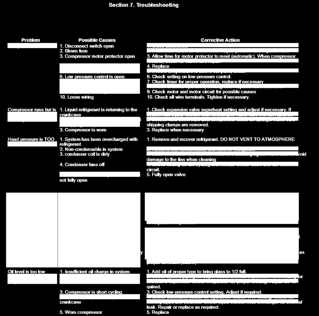
11 Section 7. Troubleshooting 11
Condensing Unit Installation and Operating Instructions
 Bulletin WCU_O&I 01 June 2003 Condensing Unit Installation and Operating Instructions WCU Air Cooled Condensing Unit Table of Contents Section 1. Section 2. Section 3. Section 4. Section 5. Section 6.
Air Cooled Condenser Installation and Operating Instructions
 Bulletin CAC_O&I 02 August 2016 Air Cooled Condenser Installation and Operating Instructions CAC Air Cooled Condensers Table of Contents Section 1. General Information... 2 Section 2. Refrigeration Piping...
CS/CD/CP AIR COOLED CONDENSING UNITS (P/N E207120C R2)
") CS*/CD*/CP* Series Air Cooled Condensing Units Operating and Installation Manual CS/CD/CP AIR COOLED CONDENSING UNITS (P/N E207120C R2) TABLE OF CONTENTS I. Receipt of Equipment 2 II. Piping...4 III. System
CS*/CD*/CP* Series Air Cooled Condensing Units Operating and Installation Manual CS/CD/CP AIR COOLED CONDENSING UNITS (P/N E207120C R2) TABLE OF CONTENTS I. Receipt of Equipment 2 II. Piping...4 III. System
Service Step by Step Trouble-Shooting Check-List
 WARNING: Only Data Aire trained technician or experience technicians should be working on Data Aire Equipment. Protect yourself at all times and work safe. Date: Dates at the job site: From: to Job#: Serial#:
Installation, Start-Up and Service Instructions
 38AH044-134 Air-Cooled Condensing Units 50/60 Hz Installation, Start-Up and Service Instructions CONTENTS Page SAFETY CONSIDERATIONS...................... 1 INSTALLATION................................
WMHP Series R410a Heat Pump INSTALLATION INSTRUCTIONS
 WMHP Series R410a Heat Pump INSTALLATION INSTRUCTIONS **WARNING TO INSTALLER, SERVICE PERSONNEL AND OWNER** Altering the product or replacing parts with non authorized factory parts voids all warranty
12 In Row. Installation Manual. MISSION CRITICAL Air Conditioning Systems. ClimateWorx International Inc.
 MISSION CRITICAL Air Conditioning Systems 12 In Row Installation Manual ClimateWorx International Inc. 14 Chelsea Lane, Brampton, Ontario, Canada L6T 3Y4 2 Table of Contents Table of Contents... 3 Site
PARALLEL RACK SYSTEM INSTALLATION & OPERATIONS MANUAL With Master Rack Compressor Sequencer
 PARALLEL RACK SYSTEM INSTALLATION & OPERATIONS MANUAL With Master Rack Compressor Sequencer 5/16 Rev. A 57-02509 2 Contents INTRODUCTION... 4 WARNING LABELS AND SAFETY INSTRUCTIONS... 5 PS SERIES PARALLEL
Series 6, Vertical Floor-Mount Units
 MISSION CRITICAL Air Conditioning Systems Series 6, Vertical Floor-Mount Units Installation Manual ClimateWorx International Inc. 14 Chelsea Lane, Brampton, Ontario, Canada L6T 3Y4 2 Table of Contents
Condensing Unit and Refrigeration System Installation & Operations Manual R448A/R449A
 Condensing Unit and Refrigeration System Installation & Operations Manual R448A/R449A 57-06 REV. -04-7_BJ TABLE OF CONTENTS INTRODUCTION... WARNING LABELS AND SAFETY INSTRUCTIONS...4 M-SERIES CONDENSING
KR Electrical Defrost Unit Coolers (PN E108318_E)
") KR Series Electric Defrost Unit Coolers Operating and Installation Manual KR Electrical Defrost Unit Coolers (PN E108318_E) TABLE OF CONTENTS 1 LOCATION RECOMMENDATIONS... 2 2 UNIT MOUNTING... 2 3 DRAIN
KR Series Electric Defrost Unit Coolers Operating and Installation Manual KR Electrical Defrost Unit Coolers (PN E108318_E) TABLE OF CONTENTS 1 LOCATION RECOMMENDATIONS... 2 2 UNIT MOUNTING... 2 3 DRAIN
ThermoSaver TM Hot Gas Defrost System
 PRODUCT DATA, APPLICATION & INSTALLATION GUIDE Supplement to Condensing Unit Installation and Maintenance Manual Bulletin K40-THERM-PDI-15 Part # 1069130 PRODUCT SUPPORT web: k-rp.com/ts email: mdcu-lgcu@k-rp.com
SERVICING PROCEDURE R-410A LEAK TEST EVACUATION CHARGING. Bard Manufacturing Company, Inc. Bryan, Ohio Manual Page 1 of 11
 SERVICING PROCEDURE R-410A LEAK TEST EVACUATION CHARGING Bard Manufacturing Company, Inc. Bryan, Ohio 43506 Since 1914...Moving ahead, just as planned. Manual No.: 2100-479 Supersedes: NEW File: Volume
Installation, Operation, and Maintenance Information
 Installation, Operation, and Maintenance Information Air Cooled Condensers 8-2016 Rev 0 Table of Contents General Safety Information 2 Inspection 2 Installation 2 6 Rigging and Assembly 2 Unit Location
KR Series Air Defrost Unit Coolers Operating and Installation Manual
 KR Series Air Defrost Unit Coolers Operating and Installation Manual KR Air Defrost Unit Coolers (PN E108317_L) TABLE OF CONTENTS 1 RECEIPT OF EQUIPMENT... 2 1.1 INSPECTION... 2 1.2 LOSS OF GAS HOLDING
Installation, Start-Up and Service Instructions
 38AH044-134 Air-Cooled Condensing Units 50/60 Hz Installation, Start-Up and Service Instructions CONTENTS Page SAFETY CONSIDERATIONS...................... 1 INSTALLATION................................
STC Series Twin Unit Coolers (E329630_A)
") STC Series Twin Unit Coolers Operating and Installation Manual STC Series Twin Unit Coolers (E329630_A) TABLE OF CONTENTS 1 RECEIPT OF EQUIPMENT 3 1.1 INSPECTION 3 1.2 LOSS OF GAS HOLDING CHARGE 3 2 ASSEMBLY
STC Series Twin Unit Coolers Operating and Installation Manual STC Series Twin Unit Coolers (E329630_A) TABLE OF CONTENTS 1 RECEIPT OF EQUIPMENT 3 1.1 INSPECTION 3 1.2 LOSS OF GAS HOLDING CHARGE 3 2 ASSEMBLY
Contour TM Screw Compressors
 Contour TM Screw Compressors Semi-Hermetic Compact Operating Instruction SCH1 High Temp Compressors Form No. 99-77 1. Introduction This series of semi-hermetic compact screw compressors is designed for
XSTREAM Valve System With A.R.M.E.D. Technology Service & Installation Instructions Page 1
 Page 1 WHY should I install the XSTREAM Valve System? XDX is more efficient, saving on power consumption. Use of XDX system decreases defrost cycles. XDX maintains more consistent product temperatures,
Installation 50% Service 20% Components 20% Applied Knowledge 10%
 LIGHT COMMERCIAL REFRIGERATION INSTALLATION CERTIFICATION Certification Information Scope - Tests a candidate's knowledge of the installation, service, maintenance, and repair of Light Commercial Refrigeration
MODELS B1PA024, 030 AND 036
 STELLAR 2000 SINGLE PACKAGE HEAT PUMPS INSTALLATION INSTRUCTION Supersedes: 511.26-N1Y (892) 511.26-N1Y (893) MODELS B1PA024, 030 AND 036 035-11622 GENERAL YORK Model B1PA units are factory assembled heat
ThermoSaver TM Hot Gas Defrost System
 PRODUCT DATA, APPLICATION & INSTALLATION GUIDE Supplement to Condensing Unit Installation and Maintenance Manual Bulletin B40-THERM-PDI-14 1069132 ThermoSaver TM Hot Gas Defrost System For use on select
CHAMPION SPLIT-SYSTEM CONDENSING UNITS (AIR COOLED) INSTALLATION INSTRUCTION Supersedes: N4 (778) N4Y (492)
 INSTALLATION INSTRUCTION Supersedes: N4 (778) N4Y (492)") CHAMPION SPLIT-SYSTEM CONDENSING UNITS (AIR COOLED) INSTALLATION INSTRUCTION Supersedes: 550.13-N4 (778) 550.13-N4Y (492) MODELS H2CA480 & 600 035-09563 GENERAL CHAMPION units are designed for outdoor
CHAMPION SPLIT-SYSTEM CONDENSING UNITS (AIR COOLED) INSTALLATION INSTRUCTION Supersedes: 550.13-N4 (778) 550.13-N4Y (492) MODELS H2CA480 & 600 035-09563 GENERAL CHAMPION units are designed for outdoor
PACKAGE AIR CONDITIONER
 PACKAGE AIR CONDITIONER FORM NO. ATZ-206 TZAA- HIGH EFFICIENCY SERIES NOMINAL SIZE 10 TON [35.2 kw] 10 TON MODEL [35.2 kw] This product is shipped with a nitrogen holding charge that must be vented prior
RDT Refrigeration Book
 RDT Refrigeration Book Indoor / Outdoor Air-Cooled Systems Indoor Air-Cooled Systems 1. Shorter line runs. 2. Systems located off roof or dock space. 3. Weather covers are not required (saves cost). 4.
G Series. G Series Air Coils Installation ti Manual ENCASED/UNCASED AIR COILS. Geothermal/Water Source Heat Pumps R-410A Refrigerant 2-5 Ton
 G Series ENCASED/UNCASED AIR COILS Geothermal/Water Source Heat Pumps R-410A Refrigerant 2- Ton Dimensional Data G Series Air Coils Installation ti Manual Installation Information Maintenance IM1018AG1
INSTALLATION MANUAL COMMERCIAL SPLIT SYSTEM COOLING UNITS 4 PIPE SYSTEMS 15 THROUGH 20 NOMINAL TON HB B-0804
 INSTALLATION MANUAL COMMERCIAL SPLIT SYSTEM COOLING UNITS 4 PIPE SYSTEMS 15 THROUGH 20 NOMINAL TON CONTENTS GENERAL................................. 3 REFERENCE............................... 3 INSPECTION...............................
WineZone Ceiling Mount Ductless Split 15
 WineZone Ceiling Mount Ductless Split 15 Requires an HVAC technician to install and charge with R-22 refrigerant. Easy to install. Unit plugs into wall outlet. Industrial grade unit for longer life. Indoor
horizontal air discharge outdoor discus condensing unit
 CC-HADTB March 2007 (Replaces CC-B-48D, 10/04) CLIMATE CONTROL horizontal air discharge outdoor discus condensing unit Technical Guide CDH Standard & Optional Features CDH Outdoor Discus Condensing Units,
CAS. Product Specifications. COMMERCIAL SPLIT SYSTEMS CONDENSING UNITS R 410A, 6 to 12.5 TONS BUILT TO LAST, EASY TO INSTALL AND SERVICE
 COMMERCIAL SPLIT SYSTEMS CONDENSING UNITS R 410A, 6 to 12.5 TONS BUILT TO LAST, EASY TO INSTALL AND SERVICE CAS Product Specifications Single stage cooling capacity control on all models with Micro channel
Installation, Operation, and Maintenance Information
 Installation, Operation, and Maintenance Information Low Velocity Unit Coolers Bulletin No. IOM 110.3 Table of Contents Inspection... 2 Installation... 2 4 General... 2 Location... 2 Drain Line... 3 Refrigerant
P-Series, Vertical Floor-Mount Units
 MISSION CRITICAL Air Conditioning Systems P-Series, Vertical Floor-Mount Units Installation Manual ClimateWorx International Inc. 14 Chelsea Lane, Brampton, Ontario, Canada L6T 3Y4 - 2 - SP-IM2018 Table
MYSTICOOL Max Valve System with Xstream and A.R.M.E.D. Technology Service & Installation Instructions Page 1
 Page 1 WHY should I install the MYSTICOOL Max Valve System? XDX is more efficient, saving on power consumption. Use of XDX system decreases defrost cycles. XDX maintains more consistent product temperatures,
Installation Instructions
 24AHA4 Performance Series Air Conditioner with Puron Refrigerant 1-1/2 to 5 Nominal Tons Installation Instructions Fig. 1-24AHA4 A07532 SAFETY CONSIDERATIONS Improper installation, adjustment, alteration,
INSTALLATION GUIDE. 4AC 14* ASA1 SERIES R-410a CONDENSING UNITS R-410A ATTENTION, INSTALLER! ATTENTION, USER!
 4AC 14* ASA1 SERIES R-410a CONDENSING UNITS INSTALLATION GUIDE R-410A ATTENTION, INSTALLER! After installing the system, show the user how to turn off electricity to the unit. Point out control and switch
Series 6, Vertical Floor-Mount Units
 MISSION CRITICAL Air Conditioning Systems Series 6, Vertical Floor-Mount Units Installation Manual ClimateWorx International Inc. 14 Chelsea Lane, Brampton, Ontario, Canada L6T 3Y4 2 Table of Contents
AE October 1965 Reformatted October Hot Gas Bypass Control Systems
 Hot Gas Bypass Control Systems AE21-1160 AE21-1160 October 1965 Reformatted October 2010 On many refrigeration and air conditioning systems, the refrigeration load will vary over a wide range. This may
CROWN. Boiler Co. Santa-Fe Series. Hydronic Air Handlers INSTALLATION, OPERATION & MAINTENANCE INSTRUCTIONS
 CROWN Boiler Co Santa-Fe Series Hydronic Air Handlers INSTALLATION, OPERATION & MAINTENANCE INSTRUCTIONS These instructions must be affixed on or adjacent to the air handler Models: SAC049A20 SAC059A25
SECTION REFRIGERATION EQUIPMENT. A. Section Includes: Refrigeration equipment for insulated cold storage rooms including necessary accessories.
 SECTION 15650 REFRIGERATION EQUIPMENT PART 1 GENERAL 1.01 SUMMARY A. Section Includes: Refrigeration equipment for insulated cold storage rooms including necessary accessories. B. Related Section: 1. 11400
SM/SV-Space Master Unit Coolers (E R.0)
") SM/SV Series Space Master Unit Coolers Operating and Installation Manual SM/SV-Space Master Unit Coolers (E316008 R.0) TABLE OF CONTENTS 1 RECEIPT OF EQUIPMENT 3 1.1 INSPECTION 3 1.2 LOSS OF GAS HOLDING
SM/SV Series Space Master Unit Coolers Operating and Installation Manual SM/SV-Space Master Unit Coolers (E316008 R.0) TABLE OF CONTENTS 1 RECEIPT OF EQUIPMENT 3 1.1 INSPECTION 3 1.2 LOSS OF GAS HOLDING
INSTALLATION INSTRUCTIONS TXV Horizontal Duct Coils EHD
 TXV Horizontal Duct s EHD These instructions must be read and understood completely before attempting installation. It is important that the Blower and Duct System be properly sized to allow the system
Thomas J Kelly. Fundamentals of Refrigeration. Sr. Engineering Instructor Carrier Corporation. August 20, Page number: 1.
 Thomas J Kelly Sr. Engineering Instructor Carrier Corporation August 20, 2003 1 SESSION OBJECTIVES At the conclusion of this session you should be able to: 1. Describe the basics principles of refrigeration
TECHNICAL GUIDE. Description SPLIT-SYSTEM AIR-COOLED CONDENSING UNITS YD360, 480 & THRU 50 NOMINAL TONS YTG-B-0811
 Description These units are completely assembled, piped and wired at the factory to provide one-piece shipment and rigging. Each unit is pressurized with a holding charge of Refrigerant R-410A for storage
Commercial High-Efficiency Condensing Units
 FORM NO. A22-194 REV. 2 Supersedes Form No. A22-194 Rev. 1 Commercial High-Efficiency Condensing Units RAWL High Efficiency 6.5 & 7.5 TON MODEL [22.86 & 26.38 kw] TABLE OF CONTENTS Model Number Designation...2
PURGER INSTALLATION AND OPERATION BULLETIN PUR-SB17-02 SERVICE BULLETIN
 VALVES VESSELS SYSTEMS CONTROLS PURGER INSTALLATION AND OPERATION BULLETIN PUR-SB17-02 SERVICE BULLETIN System drawings shown in this bulletin are for illustration purposes only. Refrigeration systems
OWNER S MANUAL. Vintage Classic HEAT COOL models. Proudly Made in the USA
 OWNER S MANUAL Vintage Classic HEAT COOL models Proudly Made in the USA support@aquacomfort.com www.aquacomfort.com/service-and-support 888-475-7443 Manufacturing High Quality, High Efficiency Heat Pump
CONDENSING UNITS SPLIT-SYSTEM COOLING 6-1/3 TONS INSTALLATION INSTRUCTION MODELS H*DB076 NOMENCLATURE GENERAL LIMITATIONS INSPECTION REFERENCE
 INSTALLATION INSTRUCTION CONDENSING UNITS SPLIT-SYSTEM COOLING 6-1/3 TONS Supersedes: Nothing 550.38-N6Y (1095) MODELS H*DB076 035-13578 WARNINGS are given to alert the installer that severe personal injury,
Air-Cooled Condensers
 Air-Cooled Condenser Installation & Operation Bulletin No. H-IM-90 February 2017 Part Number 25007301 Replaces H-IM-90, October 2015 Air-Cooled Condensers Installation and Operation Guide Applicable for
TABLE OF CONTENTS. NOTE: Read the entire instruction manual before starting the installation. TROUBLESHOOTING... 13
 R 410A Duct Free Split System Air Conditioner and Heat Pump Product Family: DFS4(A/H) System, DFC4(A/H)3 Outdoor, DFF4(A/H)H Indoor NOTE: Read the entire instruction manual before starting the installation.
INSTALLATION INSTRUCTIONS TXV Horizontal Slab Coils WLSH
 TXV Horizontal Slab Coils WLSH These instructions must be read and understood completely before attempting installation. It is important that the Blower and Duct System be properly sized to allow the system
High Profile Evaporator
 PRODUCT DATA & INSTALLATION Bulletin K30-KHPA-PDI-5 Part # 1081585 PRODUCT SUPPORT web: k-rp.com/khp email: evaps@k-rp.com call: 1-844-893-3222 x520 scan: High Profile Evaporator High & Medium Temperature
Liebert Prop Fan Condensing Unit
 Liebert Prop Fan Condensing Unit 50 Hz and 60 Hz Installer/User Guide Technical Support Site If you encounter any installation or operational issues with your product, check the pertinent section of this
Calhoon MEBA Engineering School. Study Guide for Proficiency Testing Refrigeration
 Calhoon MEBA Engineering School Study Guide for Proficiency Testing Refrigeration 1. To prevent an injury when working with refrigerants, what safety precautions are necessary? 2. When halogens are in
Table of Contents. Service Procedures. Service Procedures. Measuring Superheat (4) Measuring Subcooling (5) Airflow Calculation (6-8)
 Measuring Subcooling (5) Airflow Calculation (6-8)") Table of Contents Refrigeration Cycle Service Procedures Measuring Superheat (4) Measuring Subcooling (5) Airflow Calculation (6-8) Solving Problems Identifying Low System Charge (9-11) Identifying High
Table of Contents Refrigeration Cycle Service Procedures Measuring Superheat (4) Measuring Subcooling (5) Airflow Calculation (6-8) Solving Problems Identifying Low System Charge (9-11) Identifying High
CONDENSING UNITS SPLIT-SYSTEM COOLING 1.5 TO 5 TONS INSTALLATION INSTRUCTION MODELS H*DE018 THRU H*DE060 NOMENCLATURE GENERAL LIMITATIONS INSPECTION
 INSTALLATION INSTRUCTION CONDENSING UNITS SPLIT-SYSTEM COOLING 1.5 TO 5 TONS Supersedes: 550.44-N1Y (1194) 550.44-N1Y (495) MODELS H*DE018 THRU H*DE060 035-11029 WARNINGS are given to alert the installer
TECHNICAL GUIDE DESCRIPTION SPLIT-SYSTEM AIR-COOLED CONDENSING UNITS. HA300, HB360, HB480 & HB thru 50 NOMINAL TONS (50 Hz)
") DESCRIPTION These units are completely assembled, piped and wired at the factory to provide one-piece shipment and rigging. Each unit is pressurized with a holding charge of refrigerant-22 for storage
DESCRIPTION These units are completely assembled, piped and wired at the factory to provide one-piece shipment and rigging. Each unit is pressurized with a holding charge of refrigerant-22 for storage
INSTALLATION INSTRUCTIONS
 INSTALLATION INSTRUCTIONS STELLAR AIR CONDITIONING UNIT SPLIT-SYSTEM COOLING CONTENTS GENERAL..................................... 2 NOMENCLATURE........................... 2 SAFETY...................................
INSTALLATION AND OPERATING INSTRUCTIONS
 INSTALLATION AND OPERATING INSTRUCTIONS HIGH-EFFICIENCY CONDENSING UNITS RAWD- 6 1 2 & 7 1 2 TON RAWE - 6 1 2 & 7 1 2 TON! RECOGNIZE THIS SYMBOL AS AN INDICATION OF IMPORTANT SAFETY INFORMATION!! WARNING
OPERATION INSTRUCTIONS DEMAND DEFROST CONTROL BOARD MODEL FOR USE WITH MODELS: AFFINITY, ECHELON, ACCLIMATE HEAT PUMP SERIES
 OPERATION INSTRUCTIONS DEMAND DEFROST CONTROL BOARD MODEL 500644 FOR USE WITH MODELS: AFFINITY, ECHELON, ACCLIMATE HEAT PUMP SERIES A047-001 FIGURE 1: Demand Defrost Control Module ANTI-SHORT CYCLE DELAY
INSTALLATION INSTRUCTION
 INSTALLATION INSTRUCTION CONTENTS GENERAL............................................ 2 NOMENCLATURE..................................... 2 PRODUCT CATEGORY.................................. 2 PRODUCT
INSTALLATION and OPERATING. INSTRUCTIONS for. SMZP26 Series. elf-contained Freezers
 S elf-contained Freezers INSTALLATION and OPERATING INSTRUCTIONS for Series ZERO ZONE Zero Zone, Inc. 110 N. Oakridge Dr. North Prairie, WI 53153-9792 1-800-247-4496 FAX: 1-414-392-6450 www.zero-zone.com
DLCLRA. INSTALLATION INSTRUCTIONS Outdoor Unit Single Zone Ductless System Sizes 36 to 58 TABLE OF CONTENTS
 DLCLRA INSTALLATION INSTRUCTIONS Outdoor Unit Single Zone Ductless System Sizes 36 to 58 Fig. 1 - Size 36 TABLE OF CONTENTS PAGE SAFETY CONSIDERATIONS... 2 PARTS LIST... 3 SYSTEM REQUIREMENTS... 4 WIRING...
EBAC MODEL CD425 ( ) INDUSTRIAL DEHUMIDIFIER OWNER S MANUAL
 INDUSTRIAL DEHUMIDIFIER OWNER S MANUAL") EBAC MODEL CD425 (1018110) INDUSTRIAL DEHUMIDIFIER OWNER S MANUAL Ebac Industrial Products 704 Middle Ground Boulevard Newport News, VA 23606 Tel: 757 873 6800 Fax: 757 873 3632 Website: www.ebacusa.com
EBAC MODEL CD425 (1018110) INDUSTRIAL DEHUMIDIFIER OWNER S MANUAL Ebac Industrial Products 704 Middle Ground Boulevard Newport News, VA 23606 Tel: 757 873 6800 Fax: 757 873 3632 Website: www.ebacusa.com
EBAC MODEL K100 DEHUMIDIFIER OWNER S MANUAL
 EBAC MODEL K100 DEHUMIDIFIER OWNER S MANUAL Ebac Industrial Products 700 Thimble Shoals Boulevard Newport News VA 23606-2575 Telephone (757) 873-6800 Fax (757) 873-3632 Website: www.ebacusa.com INTRODUCTION
Installation and Operation Manual
 series Installation and Operation Manual FGCEID GLASS DOOR REACH-IN This refrigerator conforms to the Commercial Refrigerator Manufacturers Association s Health and Sanitation Standard. series Page 2 INSTALLATION
Installation Instructions
 PREFERREDT SERIES AIR CONDITIONER WITH PURONR REFRIGERANT 1-1/2 TO 5 NOMINAL TONS Installation Instructions Fig. 1 --- 538A NOTE: Read the entire instruction manual before starting the installation. TABLE
REFRIGERATION AND AIR CONDITIONING RÉFRIGÉRATION ET CLIMATISATION POST-SECONDARY NIVEAU POSTSECONDAIRE
 INSTRUCTIONS AND COMPETITION DETAILS INSTRUCTIONS ET DÉTAILS DU CONCOURS REFRIGERATION AND AIR CONDITIONING RÉFRIGÉRATION ET CLIMATISATION POST-SECONDARY NIVEAU POSTSECONDAIRE 1. Test Project Details This
Parallel Rack Systems
 Parallel Rack Systems Installation & Service Manual IMPORTANT Keep in store for future reference! P/N 0427598_B July 2013 P/N 0427598_B iii TABLE OF CONTENTS INSTALLATION Shipping Damage....................
APPLICATION GUIDELINES FOR COPELAND COMPLIANT SCROLL COMPRESSORS (ZR*1 Models)
") 4-1280 Application Engineering Bulletin AE-1280R4 Revised April, 1995 APPLICATION GUIDELINES FOR COPELAND COMPLIANT SCROLL COMPRESSORS (ZR*1 Models) Introduction The Compliant Scroll Compressor has been
4-1280 Application Engineering Bulletin AE-1280R4 Revised April, 1995 APPLICATION GUIDELINES FOR COPELAND COMPLIANT SCROLL COMPRESSORS (ZR*1 Models) Introduction The Compliant Scroll Compressor has been
EBAC MODEL CD30 INDUSTRIAL DEHUMIDIFIER OWNER S MANUAL
 EBAC MODEL CD30 INDUSTRIAL DEHUMIDIFIER OWNER S MANUAL Ebac Industrial Products 704 Middle Ground Boulevard Newport News, VA 23606 Tel: 757 873 6800 Fax: 757 873 3632 Website: www.ebacusa.com UNPACKING
SPX SERIES PACKAGED AIR CONDITIONING/HEAT PUMP UNITS INSTALLATION, OPERATION AND MAINTENANCE INSTRUCTIONS
 SPX SERIES PACKAGED AIR CONDITIONING/HEAT PUMP UNITS INSTALLATION, OPERATION AND MAINTENANCE INSTRUCTIONS **WARNING TO INSTALLER, SERVICE PERSONNEL AND OWNER** Altering the product or replacing parts with
INSTALLATION, OPERATION & MAINTENANCE INSTRUCTIONS FOR INDUSTRIAL COOLERS
 INSTALLATION, OPERATION & MAINTENANCE INSTRUCTIONS FOR INDUSTRIAL COOLERS SERIES MPA, HPA SERIES MPE, HPE & JPE SERIES MPG, HPG & JPG SERIES MPH, HPH & JPH AIR DEFROST APPLICATION ELECTRIC DEFROST APPLICATION
MODELS W1LC220, 260 AND 320 STYLE B
 LIQUID CHILLER (AIR COOLED) INSTALLATION INSTRUCTION Supersedes: 570.05-NY (494) 570.05-N3Y (495) MODELS WLC0, 60 AND 30 STYLE B 035-3053 Only -5 and -46 voltage codes GENERAL YORK s WLC Packaged Air-Cooled
R Series Cooling Modules
 R Series Cooling Modules Models RCM/RPM 50 RCM 70 RM 100 RM 140 Manufactured By Energy Saving Products Ltd. Standard ESP 105.03 Refrigerant Modules (RCM/RM) Fig. 02 - Mounting brackets The cooling coil
Kolpak/RDI Refrigeration System Installation & Operation Manual
 Kolpak/RDI Refrigeration System Installation & Operation Manual Kolpak 2915 Tennessee Avenue North Parsons, TN 38363 Phone: 800-225-9916 www.kolpak.com 550006500 August 2018 www.kolpak.com 800-225-9916
Warm Case Troubleshooting Guide 9/18/2014
 Introduction Warm cases can be caused by various problems which require thorough troubleshooting. Begin the investigation with questions to store personnel asking for information such as when the last
INSTALLATION, OPERATION & MAINTENANCE INSTRUCTIONS WALK-IN COOLERS SERIES LS-LP-LA-LV
 INSTALLATION, OPERATION & MAINTENANCE INSTRUCTIONS WALK-IN COOLERS SERIES LS-LP-LA-LV 1 CONTENTS SAETY CONSIDERATIONS............. 3 INTRODUCTION................... 3 INSTALLATION STEP 1 COMPLETE PRE-INSTALLATION
Installation Instructions
 38MHR Outdoor Unit Single Zone Ductless System Sizes 09 to 24 Installation Instructions NOTE: Read the entire instruction manual before starting the installation. NOTE: Images are for illustration purposes
RCM Refrigerant Module
 Small Duct High Velocity Heating, Cooling and Home Comfort Systems RCM Refrigerant Module Installation Manual Manufactured By Module-RCM-Refrigerant-Module-Installation-0666 Refrigerant Modules (RCM) Fig.
MODELS E1FB180 & E1FB240
 SPLIT-SYSTEM HEAT PUMPS OUTDOOR UNITS INSTALLATION INSTRUCTION Supersedes: 035-16192-000 (0601) 035-16192-001-A-1001 MODELS E1FB180 & E1FB240 GENERAL The outdoor units are completely piped and wired at
Daikin Direct Expansion (DX) Cooling Coils
 Cooling Coils") Installation and Maintenance Manual IM 902 Daikin Direct Expansion (DX) Cooling Coils Group: Applied Air Part Number: IM 902 Date: February 2008 Types EN, EF, ER, EJ, EK 2008 Daikin Applied Contents Introduction...
Installation and Maintenance Manual IM 902 Daikin Direct Expansion (DX) Cooling Coils Group: Applied Air Part Number: IM 902 Date: February 2008 Types EN, EF, ER, EJ, EK 2008 Daikin Applied Contents Introduction...
Installation Instructions
 Performance Series Heat Pumps with PURONr Refrigerant 1 --- 1/2 to 5 Nominal Tons Installation Instructions Fig. 1 --- A07532 NOTE: Read the entire instruction manual before starting the installation.
Owner s Manual Refrigerated Compressed Air Dryers Models F-3528, F-3529, F-3530, F-3531 & F-3532
 Owner s Manual Refrigerated Compressed Air Dryers Models F-3528, F-3529, F-3530, F-3531 & F-3532 Read carefully before attempting to assemble, install, operate or maintain the product described. Protect
AIR CONDITIONING. Carrier Corporation 2002 Cat. No
 AIR CONDITIONING Carrier Corporation 2002 Cat. No. 020-016 1. This refresher course covers topics contained in the AIR CONDITIONING specialty section of the North American Technician Excellence (NATE)
S1CV/S1HV Single-Zone
 S1CV/S1HV Single-Zone Variable Speed Ductless Split-System Condensing Units and Heat Pumps with R1A Refrigerant Capacities Single-Zone Applications S1CV or S1HV Units 9, 12, 18, 2, Btuh COOL 2.6 3.5 5.3
Data Aire, Inc. reserves the right to make design changes for the purpose of product improvement or to withdraw any design without notice.
 Data Aire, Inc. reserves the right to make design changes for the purpose of product improvement or to withdraw any design without notice. Table of Contents 1.0 Introduction 1.1 Inspection...4 1.2 Description...4
Liebert Small System MCD and PFH Condensers (1-5 Ton) Warranty Inspection Check Sheet
 Warranty Inspection Check Sheet") The following information must be fully completed and forwarded to your local Liebert sales office to establish your equipment warranty. Installer Address Owner Address Owner e-mail address Installation
The following information must be fully completed and forwarded to your local Liebert sales office to establish your equipment warranty. Installer Address Owner Address Owner e-mail address Installation
Series 11, Ceiling Units
 MISSION CRITICAL Air Conditioning Systems Series 11, Ceiling Units Installation Manual ClimateWorx International Inc. 14 Chelsea Lane, Brampton, Ontario, Canada L6T 3Y4 Table of Contents Table of Contents...
R Series Cooling Modules
 TM Small Duct High Velocity Heating, Cooling and Indoor Air Quality Systems R Series Cooling Modules Models RCM-50 RCM-70 RM-100 Manufactured By Module-RCM/RM-Series-Installation-Manual-120113 Refrigerant
INSTALLER'S GUIDE. ALL phases of this installation must comply with NATIONAL, STATE AND LOCAL CODES
 11-AC11D2-5 INSTALLER'S GUIDE ALL phases of this installation must comply with NATIONAL, STATE AND LOCAL CODES Models: Condensing Units 2A7A5024-048, 2A7A4018-060, 2A7A2018-060 & 2A7A1018-060 IMPORTANT
Air Conditioning Operation and Troubleshooting Matt Dunham
 Air Conditioning Operation and Troubleshooting Matt Dunham Major Components (10 Minutes) Compressor heart of the system, causes refrigerant to flow by increasing the pressure of the refrigerant Metering
BASIC HEAT PUMP THEORY By: Lloyd A. Mullen By: Lloyd G. Williams Service Department, York Division, Borg-Warner Corporation
 INTRODUCTION In recent years air conditioning industry technology has advanced rapidly. An important byproduct of this growth has been development of the heat pump. Altogether too much mystery has surrounded
Technical Development Program. COMMERCIAL HVAC PACKAGED EQUIPMENT Split Systems PRESENTED BY: Ray Chow Sigler
 Technical Development Program COMMERCIAL HVAC PACKAGED EQUIPMENT Split Systems PRESENTED BY: Ray Chow Sigler Menu Section 1 Section 2 Section 3 Section 4 Section 5 Section 6 Section 7 Introduction System
DT/DTX Series Unit Coolers (R0 E316013)
") DT/DTX Series Unit Coolers Operating and Installation Manual DT/DTX Series Unit Coolers (R0 E316013) TABLE OF CONTENTS 1 RECEIPT OF EQUIPMENT 3 1.1 INSPECTION 3 1.2 LOSS OF GAS HOLDING CHARGE 3 2 ASSEMBLY
DT/DTX Series Unit Coolers Operating and Installation Manual DT/DTX Series Unit Coolers (R0 E316013) TABLE OF CONTENTS 1 RECEIPT OF EQUIPMENT 3 1.1 INSPECTION 3 1.2 LOSS OF GAS HOLDING CHARGE 3 2 ASSEMBLY
TRI-PLATE B INSTALLATION, OPERATION, AND MAINTENANCE INSTRUCTIONS PART NO EFFECTIVE MARCH 1, 1983 REPRINT APRIL 16, 1999
 TRI-PLATE B INSTALLATION, OPERATION, AND MAINTENANCE INSTRUCTIONS PART NO. 8801469 EFFECTIVE MARCH 1, 1983 REPRINT APRIL 16, 1999 THE MILK COOLING SYSTEMS SPECIALISTS TM FRE-HEATER Part No. 8801469 Table
Product Data. Features/Benefits. GEMINI 38AKS Commercial Air-Cooled Split Systems 50/60 Hz. 25 to 40 Nominal Tons (82.8 to 127.
 Product Data GEMINI 38AKS028-044 Commercial Air-Cooled Split Systems 50/60 Hz 25 to 40 Nominal Tons (82.8 to 127.0 kw) These dependable split systems match Carrier s indoor-air handlers with outdoor condensing
CHAMPION SPLIT-SYSTEM EVAPORATOR BLOWER DESCRIPTION FEATURES L2EU NOMINAL TONS
 550.23-TG5Y (893) CHAMPION SPLIT-SYSTEM EVAPORATOR BLOWER L2EU240 20 NOMINAL TONS DESCRIPTION This 20 ton evaporator blower is designed with two distinct modules to provide maximum application flexibility.
Catalog Air Cooled Split System Condensing Units for Rooftop Systems and Air Handlers
 Air Cooled Split System Condensing Units for Rooftop Systems and Air Handlers Models RCS 025C through 135C 25 to 135 Tons R-22/R407C Refrigerant Catalog 221-1 Table of Contents Introduction.... 3 The Condensing
CAUTION. Check Equipment and Job Site. Clearance Requirements. Unpack Unit
 INSTALLATION IMPORTANT: Effective January 1, 2015, all split system and packaged air conditioners must be installed pursuant to applicable regional efficiency standards issued by the Department of Energy.!
Owner s Manual Refrigerated Compressed Air Dryer Model F-50
 Owner s Manual Refrigerated Compressed Air Dryer Model F-50 Read carefully before attempting to assemble, install, operate or maintain the product described. Protect yourself and others by observing all