TECH - SPEC S Technician s Pocket Guide
|
|
|
- Ginger Elliott
- 5 years ago
- Views:
Transcription
1 TECH - SPEC S Technician s Pocket Guide #80050 This technicians pocket guide covers all Hoshizaki H-Series ice maker models. Additional technical information, full parts, and service manuals are available for review and download on the Tech Support page of the Hoshizaki web site. See for manuals, Tech- Tips, and additional technical information on Hoshizaki products. See Tech-Spec s #80024 purple pocket guide for older models using R-12/502 refrigerant. See Tech-Spec s #80021 green pocket guide for E-Series models using R-22. See Tech-Spec s #80045 orange pocket guide for F and early H series ice maker models. These guides can be downloaded from the Hoshizaki web site or purchased through your local Hoshizaki Distributor. 1
2 TABLE OF CONTENTS PAGE Code Registration... 9 Coverage... 9 General Specs Plumbing Requirements (All) Condensate Drain Flow Rates (All) Filtration Electrical Connections Transformer Application (Optional) Condenser Chart Remote Lines Remote Cond. Installation Diagram Line Set Installation System Charge Cuber Charge Chart URC Charge Chart Refrigerant Oil Flaker/DCM Charge Chart Heat Load for AC & Cooling Tower...25 Cuber Heat Load Chart Flaker & DCM Heat Load Chart E Control Board Adjustment Guide E Board Factory Dip Switch Settings G & H Board Adjustment Guide G Board Factory Dip Switch Settings H Board Factory Dip Switch Settings E Control Board Functions Manual Reset Safeties E Control Board Label G Control Board Label Positive Hearvest Feature...38 H Control Board Label Compressor Data Water-Cooled Head Controls Remote Head Controls High Safety Switch Switch Chart Bin Control - Thermostatic Mechanical F/DCM
3 PAGE Basic KM Sequence Flow Chart KM-251/255 BAH/BWH Sequence Flow Chart KM-61~260B & KMD Sequence Flow Chart KMS-1230/1400 MLH Sequence Flow Chart KM-10 Minute Check Out Reservoir Flush System Pump-Out Check Valve...60 KML Pump-Out...60 KM Control Switch Control Board Fuse Control Board Fuse Label Float Switch...64 Thermistor Control Board Board Checkout Bin Control - Thermostatic...69 Mechanical F/DCM KM Control Transformer Pump Assemblies - KML Smaller KM s Larger KM s...75 Inlet Water Valve...76 CKD Valves...77 Invensys, EATON, and other Valves...77 Water Valve Coil Freeze Up Check List...81 Preventative Maintenance...83 Cleaning/Sanitizing Procedure...83 KM Production Check KM-61BAH KM-101BAH KM-151BAH KM-201B_H KML-250M_H KM-251BAH KM-255BWH KM-260B_H KM-280M_H KM-280M_H-E KM-320M_H KM-320MAH-E
4 PAGE KML-350M_H KML-351M_H KML-450M_H KML-451M_H KM-461M_H DKM-500B_H KM-500MAH-E KM-501M_H KM-515M_H KM-515MAH-E KM-600MAH KML-600M_H KML-600MWH Serial L0-M KM-630M_H KM-630MAH-E KML-631M_H KM-650M_H KM-650MAH-E KMD-700M_H KMS-750MLH & SRK-7H KMD-850M_H KM-900M_H KM-900MRH KM-900MAH KMD-900M_H KM-901M_H KM-901MRH KMD-901M_H KMS-1230MLH & SRK-13H KM-1300M_H KM-1300S_H KM-1300S_H KM-1300SAH-E KM-1301S_H KM-1301S_H KM-1340M_H KMS-1400MLH & SRK-14H KM-1600MRH KM-1600MRH KM-1600S_H KM-1600S_H KM-1601MRH KM-1601MRH KM-1601S_H KM-1601S_H KM-1800S_H KM-1800S_H KM-1900S_H KM-1900S_H
5 PAGE KM-2000S_H KM-2100 S_H KM-2400 SRH KM-2500 S_H Pin Connector KM Wiring Diagram Reference Chart General Installation Cubelet Models Internal Auger Design Control Transformer Gear Motor Protection Gear Motor Checkout Auger Bearings, Inspection & Replacement Dual Float Switch Dual Float Switch Drawing Flaker Water FIll System Flaker Timer Board Flaker Sequence of Operation Flaker Periodic Flush FD Flush Flaker Sequence Flow Chart Flush/Low Water Safety Flow Chart New FD Control Board FD Board S1 Dip Switch Adjustment Chart FD Control Board Drawing FD Bin Control #2 Flow Chart DCM Sequence of Operation Flaker/DCM Production Check DCM-500/750B_H Timer Board DCM-500/750B_H Timer Board Flow Chart DCM-500/750B_H-OS Timer Flow Chart DCM-270 BAH (-OS) DCM-500 B_H(-OS) DCM-750 B_H-OS DKM-500 B_H DT-400 BAH-OS F-330 BAH F-450 MAH-C F-800 M_H F-800 M_H-C F-801 M_H
6 PAGE F-801 M_H-C F-1001 M_H F-1001 M_H-C F-1001 MLH (-C) F-1500 M_H F-1500 M_H-C F-2000 M_H (3) F-2000 M_H-C F-2000 MLH (-C) FS-1001 MLH-C Notes
7 HOSHIZAKI MODEL NUMBER IDENTIFICATION CODE ex. KM-1300SAH-E Code - Designation KM - UNIT TYPE B - Bin DB - Dispenser Bin DCM - Dispenser Cubelet Maker DKM - Dispenser KM Combo DM - Countertop Dispenser DT - DCM/F Combo F - Flaker FD - Dispenser model (24 deep) FS - Flaker Serenity KM - Crescent Cuber KMD - Dispenser model (24 deep) KMS - KM Serenity PRODUCTION Approximate production/24 70 F Air/50 F Water S - UNIT STYLE B - Self contained with bin M - Modular S - Stackable A - CONDENSER STYLE A - Air Cooled L - Low Side R - Remote Air Cooled W - Water Cooled H - GENERATION/SERIES Model designation H - R404A latest model E - SPECIAL MODEL DESIGNATION HZ. C - Cubelet E - European - 50 HZ. OS - Opti-Serve 7
8 HHOSHIZAKI ICE MAKER MMODEL NUMBER SSERIAL NUMBER AAC SUPPLY VOLTAGE CCOMPRESSOR FAN MAXIMUM FUSE SIZE MAX. HACR BREAKER (USA ONLY) MAX. CIRC. BREAKER (CANADA ONLY) MINIMUM CIRCUIT AMPACITY DESIGN PRESSURE REFRIGERANT MMOTOR-COMPRESSOR THERMALLY PPROTECTED HOSHIZAKI AMERICA, INC. LISTED ICE MAKER WITHOUT STORAGE MEANS 946Z C NSF v tions. This Nameplate is located on the upper right hand side of rear panel. Since this Nameplate is located on the rear panel of the icemaker, it cannot be read when the back of the icemaker is against a wall or another piece of kitchen equipment. Therefore, the necessary electrical and refrigeration information is also on the rating label, found by removing the front panel of the icemaker. We reserve the right to make 8
9 Warranty registration is available online and a registration card is supplied with the equipment. Registration must be must be completed to initiate warranty. The warranty begins on the date of installation if registration procedures are followed. If registration is not completed, the warranty date will be the date of sale or date of shipment from the factory, respectively. The warranty will cover defects in material or workmanship under normal and proper use and maintenance service limited to the repair or replacement of parts or assemblies that in Hoshizaki s opinion are defective. ITEM PRODUCT PARTS LABOR Total Unit Standard bin DB/DM F/DCM KM Cuber 3 Years 1 Year 2 Years 3 Years 1 Year 2 Years Compressor & Air- Cooled Condenser KM Cuber F/DCM 5 Years 5 Years 3 Years 2 Years Evaporator Plate KM Cuber 5 Years 5 Years Evaporator, Auger F/DCM 2 Years 2 Years Gear Motor Assy. Accessory Large Bin 5 Years 5 Years Drain Pump Other 1 Year 90 Days See Warranty Statement supplied with the unit for details. Warranty valid in United States, Canada, Mexico, Puerto Rico, and U. S. Virgin Islands. Contact factory for warranty in other countries, territories, or possessions. 9
10 The ice machine is not intended for outdoor use. Operating Conditions - ALL MODELS Item Model Voltage Range 115V units 104~127V V units 187~264V or 230V 198~254V Ambient Temp. All 45~100 F Remote Condenser -20~122 F Water Supply All 45~90 F Temp. Water Supply All 10~113 PSIG Allow 6 clearance at rear, sides, and top for proper air circulation and ease of maintenance or service. 20 top clearance for F/DCM. Water Supply: On KM units the water supply line size is critical due to the water assisted harvest and the use of a ported inlet water valve solenoid. Model Line Size KM- 61 ~ KM-900 3/8 OD 1/2 FPT KM-1300 ~ KM /2 OD 1/2 FPT All F/DCM 3/8 OD 1/2 FPT *Water cooled condenser units require two separate supplies sized as per list above. Drain Connections:*Some models have 2 drain outlets. Model Line Size All Bins 3/4 OD 3/4 FPT All KM models 3/4 OD 3/4 FPT 10
11 Model Line Size Flakers/DCM 3/4 OD 3/4 FPT* Water Cooled Condenser Outlet: KM-151BWH, KM-250BWH, KM-255BWH, KM-1600SWH, KM-1600SWH3, KM-2000SWH3 have 1/2 FPT outlet. All other KM, KML, KMD, Flaker, and DCM models have 3/8 FPT outlet. Hoshizaki recommends that the ice machine drain and bin drain be piped separately to the drain connection point allowing 1/4 per foot fall. The condensate drain is generally connected to the ice ate Drain Reservoir D Note: the reservoir or drain pan! 11
12 maker units are as follows: Models KM-61/101/151/ ~0.31 KM-201B/251B/260B/320M, KML-351MWH, KML-451M 0.53 DKM-500B, KML-250/350/450/631, KML-351MAH, KM-461/501/515/901M All F/DCM s 0.8 KM-515M-E/650M-E 1.06 KMD-450/700/900M, KML-600M, KM-500/600/650M 1.58 KM-630/900/1340/1601M, KM-900M50, KM-630M-E, KMD-850M/901M, KMS-750/1230/1300/ KM-1601S/1801S/2001S/2500S 3.0 KM-1800S/2000S/2400S 3.34 KM-1300S/1600S, KM-1300S-E, KM-1301S, KM-1301S-E 3.96 quality. In some cases, treatment is needed to address water hardness, or high mineral content. There are many possibilities for water treatment: In gen- bon is used for taste and odor and polyphosphate is used for scale control. There are also other possibilities, such as a water softener (not recommended for F/DCM s), or in some cases, reverse osmosis (RO). RO can be aggressive, but is acceptable if the RO output has a neutral ph of 7. See your local Hoshizaki distributor, or a water expert, for the best recommendation for your area. Note: Filtration, or treatment, must be sized properly to lems with production and operation of the icemaker. 12
13 115V. (2 wire w/gnd) 115V. Neutral GND Brown White V/1 Phase units require a dedicated neutral due to the use of 115V components V. (3 wire w/gnd) 115V. Neutral 115V. GND Brown White Black The dedicated neutral requires an insulated conductor which runs directly to the panel. If high leg is present, connect to black wire. A transformer can be used to provide 115V control circuit V. 3 phase (3 wire w / gnd) 115V. 115V. 115V. GND Black W or R Brown Fan Control Circuit From Unit 115V. Neutral GND Brown White Note: All Electrical connections must be made in accordance with all national and local electrical codes. 13
14 All 208V-230V 3 ph models include a 115V transformer with a 208/230V selector switch. - (Voltage from the center tap to case ground will be 67.5V due to the transformer circuit.) 208/230V models include 115V controls. They require a 115/ V circuit which has 4 wires: L1, L2, dedicated neutral, and ground. If a dedicated neutral is not available, or the previous unit used a 3 wire circuit (L1,L2, & gnd.), a step-down transformer can be used at the unit to provide power to the 115V components. This will save on installation time and cost if a dedicated neutral is not present. Transformer #4A or equivalent can be used for KM models. Transformer # or equivalent can be used for F-1000 models. The transformer should be mounted inside the compressor compartment and wired using the following generic diagram. 14
15 Condenser Model URC-5F KM-461/515M/650M, *F-1001M, FD-1001M URC-6F KM-500/501/630M, *F-1001M URC-7F KML-600M URC-9F KML-631M, KMD-850/901M URC-12F KM-900/1300M, KM-1300S, *KMD-700M, KMD-900M, *F-1500 URC-14F KM-1340M, KM-1301S, *KMD-700M, *F-1500 URC-20F KM-1600M, KM-1600/1800/ 2000S, F-2000M URC-21F *KM-1601M/S, *KM-1900S URC-22F *KM-1601M/S, *F-2000M, *KM-1900S, KM-2100S URC-23F KM-2500S URC-24F KM-2400S SRC-10H FS-1001MLH SRK-7H KMS-750MLH SRK-13H KMS-1230MLH SRK-14H KMS-1400/1401MLH SRK-14H3 KMS-1401MLH *Model has 2 possible matches. When installing a remote application the unit/condenser combination must match with the above chart. A non-oem multi-pass condenser can be used with prior written factory approval. See service bulletin SB R1 15
16 Remote Lines Hoshizaki has 3 precharged line set lengths available: 20 ft, 35 ft, and 55 ft. The line sets are available in different sizes for different models. ex. R R404 - Refrigerant 35 - Length In Feet 6 - Liquid Line Size in 16th s 10 - Discharge Line Size in 16th s Line Set Applications Models Line Set KM-461/500/515/650MRH, F-1001MRH, FD-1001MRH KML-600 KM-900/901MRH, KM-1300/1301/1340M/S, KML-631MRH, KMD-700/850/900/901MRH, F-1500M KM-1600/1601M/S/3 KM-1800/1900/2000S/3 KM-2100S/3 KM-1800SRH/3) KM-2500SRH3 KM-2400SRH/(3) F-2000MRH/3/-C KMS- 750/1230/1400/1401MLH FS-1001MLH R R R R R R R R R R R R R R R /4 OD-3/8 OD 3/8 OD-1/2 OD 3/8 OD-5/8 OD 1/2 OD-5/8 OD 1/4 OD-5/8 OD 16
17 Allow 24 for air circ Air Flow out louver. s b The Rem denser sh be more t above the or more t below it. These dis are meas 2½ Dia. roof for tu Seal after lation to p leaking 17

 2. Pressurize the lines and leak check all braze joints. 3.")
18 Universal line set adapter kits (part number OS-QUICK for KM and HS-0231 for KMS) are available if you need to separately the entire length of run. The refrigerant charge for a new unit is distributed between the unit head and the URC condenser. The line set has a minimal holding charge of 15 to 30 psig refrigerant vapor. a precharged line set, you can do so by following these steps: 1. Using the correct connector kit, braze the line set connection. (If you shorten or lengthen a precharged line set, recover the holding charge, cut/lengthen, and braze the connections.) 2. Pressurize the lines and leak check all braze joints. 3. Evacuate the lines through the service ports on the 4. Charge both lines with 15 to 30 psig R-404A vapor. To make quick connect connections: 1. Lubricate threads and O-rings with clean refrigerant oil. 2. Align the male and female couplings straight. 3. Tighten the female connector until it bottoms out. Note: Always use a back up wrench when tightening 4. Once secure, mark a reference line and turn the brass seal. 5. Leak check the joints with soap bubbles or electronic leak detector. 18
19 The ice machine head and URC condenser are shipped with enough refrigerant charge for up to 66 ft. of line set length. The maximum line set length is 100 equivalent feet from the head to the condenser. For applications longer than 66 ft. (up to the maximum 100 ft. length), additional refrigerant must be added. For any length over 66 ft. add 0.4 oz. per foot. For units utilizing 3/8 L.L. no line size change is needed. For units utilizing 1/4 L.L. and 3/8 D.L., the line size should be increased to 3/8 L.L. and 1/2 D.L. for the entire length of the run then add 16.5 oz oz. per foot over 66 foot. Note: (1) Recommended line sizes are same as listed in the line set application chart. (2) Older models utilize R-502 refrigerant or R-22 refrigerant. Always check the unit nameplate for the correct refrigerant type. (3) If refrigerant is added due to extended line set length, mark the correct total charge on the unit nameplate for future reference. (4) When routing and installing remote lines, always use standard refrigerant piping practices. (5) Hoshizaki recommends eliminating any excess loops in a pre-charged line set application before making the unit connections. This will eliminate oil traps and possible crimps in the excess tubing. (6) A service loop can be included behind the unit as shown in the illustration on page 13 to allow the unit to be moved away from the wall if needed. The total system charge is criti- tion. Always weigh in the proper charge, per the following charge chart. (Remote units show standard charge good for up to 66 ft.) Unit charge information is also found on the unit Nameplate
20 Model KM-61BAH 6.4 oz R134A KM-101BAH 7.8 oz R134A KM-151BAH 8.5 oz R134A KM-151BWH 10.7 oz R134A KM-201BAH 12 oz R404A KM-201BWH 11 oz R404A KM-251BAH 15 oz R404A KM-255BAH 1 lb 1 oz R404A KM-260BAH 12.7 oz R404A KM-260BWH 13.8 oz R404A KM-280MAH(-E) 12 oz R404A KM-320MAH(-E) 1 lb 4.3 oz R404A KM-320MWH 1 lb 0.8 oz R404A KM-461MAH 1 lb 11.5 oz R404A KM-461MRH 5 lbs 4.7 oz R404A KM-461MWH 1 lb 2.5 oz R404A KM-500MAH(-E) 1 lb 10 oz R404A KM-501MRH 4 lbs R404A KM-501/515MWH 15 oz R404A KM-501MAH 1 lb 10 oz R404A KM-515MAH 1 lb 7.3 oz R404A KM-515MAH-E 1 lbs 2.5 oz R404A KM-515MRH 4 lbs 4.8 oz R404A KM-600MAH 1 lbs 11 oz R404A KM-630MAH(-E) 1 lb 6 oz R404A KM-630MRH 4 lbs 4 oz R404A KM-630MWH 1 lb 4.3 oz R404A KM-630MWH-LO-M1 1 lb 3 oz R404A NOTE: To convert to grams multiply oz. x
21 Model KM-630MWH-M2 1 lb 4.3 oz R404A KM-650MAH(-E) 1 lb 6.6 oz R404A KM-650MRH 5 lbs 11 oz R404A KM-650MWH 1 lb 5.7 oz R404A KM-900MAH(-50) 3 lbs 7 oz R404A KM-900MRH(3) 9 lbs 14 oz R404A KM-900MWH(3) 1 lb 14 oz R404A KM-900MWH-L0-M2 1 lb 7 oz R404A KM-901MAH 2 lbs 15 oz R404A KM-901MRH(3) 9 lbs 4 oz R404A KM-901MWH 1 lb 15.4 oz R404A KM-1300MAH 4 lbs R404A KM-1300MRH 9 lbs 15 oz R404A KM-1300MWH 2 lbs 9 oz R404A KM-1300SAH(3)(-E) 3 lbs 14 oz R404A KM-1300SRH(3) 11 lbs 7 oz R404A KM-1300SWH(3) 2 lbs 2 oz R404A KM-1301SAH 3 lbs 15.5 oz R404A KM-1301SAH-E 3 lbs 9.1 oz R404A KM-1301SRH(3) 10 lbs 5.8 oz R404A KM-1301SWH(3) 2 lbs 8.2 oz R404A KM-1340MAH 4 lbs 11.4 oz R404A KM-1340MRH 9 lbs 14.7 oz R404A KM-1340MWH 2 lbs 9 oz R404A KM-1600SWH(3) 3 lbs 1 oz R404A KM-1600M/SRH(3) 14 lbs 12 oz R404A KM-1601MRH(3) 24 lbs 4.0 oz R404A KM-1601SRH(3) 24 lbs 14.6 oz R404A KM-1601SWH(3) 3 lbs 1 oz R404A 21
22 Model KM-1800SAH(3) 4 lbs 7 oz R404A KM-1800SRH(3) 15 lbs 7 oz R404A KM-1800SWH(3) 3 lbs 2 oz R404A KM-1900SAH(3) 4 lbs 10.1 oz R404A KM-1900SRH(3) 23 lbs 7.7 oz R404A KM-1900SWH(3) 3 lbs 1.4 oz R404A KM-2000SRH3 16 lbs 2 oz R404A KM-2000SWH3 3 lbs 7 oz R404A KM-2400SRH3 24 lbs R404A KM-2500SWH3 4 lbs 11.5 oz R404A KM-2500SRH3 24 lbs 12.3 oz R404A KMD-450MAH 1 lb 5.2 oz R404A KMD-450MWH 1 lb 0.9 oz R404A KMD-700MAH 2 lbs 8.6 oz R404A KMD-700MRH 10 lbs 0.5 oz R404A KMD-700MWH 1 lb 10 oz R404A KMD-850MAH 2 lbs 8.2 oz R404A KMD-850MRH 9 lbs 4.2 oz R404A KMD-850MWH 1 lb 12.6 oz R404A KMD-900MAH 3 lbs 8.3 oz R404A KMD-900MRH 9 lbs 6 oz R404A KMD-900MWH 2 lbs R404A KMD-901MAH 4 lbs 3 oz R404A KMD-901MRH 9 lbs 14.7 oz R404A KMD-901MWH 2 lbs 3.3 oz R404A KML-250/350MAH 1 lb 2 oz R404A KML-250MWH 14.1 oz R404A KML-350MWH(-M3) 13.5 oz R404A KML-351MAH/MWH 1 lb 2 oz R404A KML-450MAH 1 lb 6 oz R404A 22
23 Model KML-450MWH 15.8 oz R404A KML-451MAH T0 & T2 1 lb 13.1 oz R404A KML-451MAH T1, U1> 1 lb 8.7 oz R404A KML-451MWH < U0 1 lb 2.3 oz R404A KML-451MWH U1> 15.2 oz R404A KML-600MAH 2 lbs 4 oz R404A KML-600MRH 10 lbs 6 oz R404A KML-631MAH 2 lbs 10.3 oz R404A KML-631MRH 9 lbs 8.4 oz R404A KML-631MWH 1 lb 9.6 oz R404A KMS-1230MLH KMS-1400MLH 16 lbs 5 oz R404A KMS-750MLH 10 lbs 11 oz R404A (Condenser charge is included in total charge.) Model URC-5F/6F 1lb 14oz R404A URC-7F 2lbs 5oz R404A URC-9F 3lbs 14.8oz R404A URC-12F 4lbs 7oz R404A URC-14F 4lbs 7oz R404A URC-20F 7lbs 11oz R404A URC-21F 9lbs 11oz R404A URC-22F 7lbs 11.5oz R404A URC-23F 9lbs 11oz R404A URC-24F 11lbs R404A SRC-10H 8lbs 6oz R404A SRK-7H 10lbs 4oz R404A SRK-13H/14H/14H3 15lbs 14oz R404A 23
24 All R-404A models use Polyol Ester (POE-EAL) oil. POE oil absorbs moisture easily. Extra care must be taken to reduce the possibility of moisture entering the system during service. If moisture contamination is suspected, the oil should be changed and the liquid line drier must be replaced. Changing the oil requires removal of the compressor so that the oil can be drained and replaced with the correct amount. See compressor data chart for oil amount. Replacement compressors are shipped with POE oil. Model DCM-270BAH 14.8 oz R404A DCM-500BAH 1 lb 4.1 oz R404A DCM-500BWH 14.1 oz R404A DCM-750BAH 1 lb 7.1 oz R404A DCM-750BWH 1 lb 2.7 oz R404A DKM-500BAH 2 lbs R404A DKM-500BWH 1 lb 2 oz R404A DT-400BAH-OS 1 lb 1 oz R404A F-330BAH(-C) 7.1 oz. R404A F-450MAH(-C), F-500BAH(-C) 1 lb R404A F-800MAH(-C) 1 lb 10 oz R404A F-800MWH(-C) 13.8 oz R404A F-801MAH(-C) 1 lb 12 oz R404A F-801MWH(-C) 1 lb 1 oz R404A F-1001MAH(-C) 1 lb 12 oz R404A F-1001MAH-22C 1 lb 7 oz R404A F-1001MLH(-C) 3.5 oz R404A F-1001MRH(-C) 4 lbs 1 oz R404A F-1001MWH(-C) 15 oz R404A F-1500MAH(-C) 2 lbs 5 oz R404A F-1500MRH(-C) 9 lbs 9 oz R404A 24
25 Model F-1500MWH(-C) 1 lb 4 oz R404A F-2000MLH(-C) 3.5 oz R404A F-2000MRH(3)(C) 14 lbs 9 oz R404A F-2000MWH(-C) 2 lbs R404A FD-1001MAH-C 1 lb12 oz R404A The heat of rejection information listed below by model number should be used for sizing air conditioning equipment or water-cooled cooling tower applications. r. Model Air Cooled KM-61BAH 1, KM-101BAH 2, KM-151BAH 3,840 3,840 KM-201BAH 4,120 4,120 KM-251BAH 5,300 5,300 KM-255BAH 4,100 4,100 KM-260BAH 4, KM-280MAH(-E) 8, KM-320M_H 7,400 5,700 KM-1300M_H 19,800 15,185 KM-1300S_H 19,800 15,560 KM-1300S_H3 18,130 15,450 KM-1300SAH-E 20, KM-1301S_H(3) 20,300 17,600 KM-1301SAH-E 19, KM-1340M_H 22,600 20,500 KM-1600S_H ,220 KM-1600S_H ,560 KM-1601S_H ,100 KM-1601S_H ,500 25
26 Model Air Cooled KM-1800S_H 24,720 26,200 KM-1800S_H3 24,150 25,900 KM-1900S_H 23,800 26,800 KM-1900S_H3 23,700 27,100 KM-2000S_H ,170 KM-2100SWH ,100 KM-2500SWH ,500 KM-320MAH-E 5, KM-461M_H 7,800 7,300 KM-500MAH-E 7, KM-501M_H 9,200 6,800 KM-515M_H 9,600 8,300 KM-515MAH-E 10, KM-600MAH 9, KM-61BAH 1, KM-630M_H 9,639 8,770 KM-630MAH-E 10, KM-650MAH 10,600 10,000 KM-650M_H-E 9,800 10,000 KM-900M_H 14,800 13,000 KM-900MAH-50 14, KM-901M_H 15,400 13,500 KMD-450M_H 7,700 6,800 KMD-700M_H 14,590 12,200 KMD-850M_H 13,200 10,400 KMD-900M_H 18,865 13,480 KMD-901M_H 16,300 12,400 KML-250M_H 5,560 5,000 KML-350M_H 6,550 5,600 26
27 Model Air Cooled KML-350MWH L0~M ,370 KML-351M_H 6,550 5,500 KML-450M_H 7,480 6,180 KML-451M_H 7,100 6,400 KML-600M_H 11,580 9,850 KML-631M_H 11,600 9,900 Model Air Cooled DCM-270B 3, DCM-500B 6,300 5,438 DCM-750B 8,314 7,945 DKM-450 8,098 6,900 DT-400B 4, C-100BAE-AD F-330BAH(-C) 3, F-450MAH(-C) 5, F-800M_H(-C) 7,500 6,270 F-801M_H(-C) 6,398 5,155 F-1001M_H(-C) 9,050 7,110 F-1500M_H(-C) 15,323 13,874 F-2000M_H ,530 FD-1001MAH-C 8,800 7,110 Figures shown are at 90 F air temp. 70 F water temp. conditions. Always allow for a pressure differential of 10 psi across the water cooled condenser. This means that the inlet pressure must be at least 10 psi higher than the water regulating valve and condenser. 27
28 The early E boards have 8 dip switches. The latest E boards have 10 dip switches. E Board Dip Switch Setting Guide ADJUSTMENTS DIP # Switch Code 1=ON 0=OFF DEFROST COMPLETION TIMER seconds PUMP OUT TIME Length of pump out seconds Min Defrost Time seconds Inlet Water Valve status OFF OFF ON OFF PERIODIC PUMP OUT FREQUENCY BIN CONTROL SWITCH TEST 8 MAX. FREEZE TIME (Improved E board only.) cycles 1/1 1/2 1/5 1/10 7 OFF for thermostatic contol 9 10 minutes ON for mechanical control /50hz 60/60hz ALWAYS OFF Default NOTE: 1. Adjust switches 1&2 to out 1/1. Do not adjust 1&2 on KM150/250 in high ambient area. 2. from factory setting. 3. unless a special bin control / red connector is provided. Dip switch 7 must be ON in this case. 4. Dip-switches 9&10 are on improved E board only. 28
29 Model KM-280MAH KM-280MWH KM-320MA/WH KM-320MAH-E KM-461MAH KM-461MRH KM-461MWH KM-501MAH KM-501MW/RH KM-600/650MAH KM-515MAH(-E) KM-1900SAH(3) KM-1900SWH(3) KM-650MAH-E KM-650MRH KM-650MA/WH KM-900MAH KM-901M_H(3) KM-900M_H(3) KM-1300MWH KM-1340MWH KM-1600MRH(3) KM-1601MRH(3) KM-1300MAH KM-1300S_H(3) KM-1340MAH KM-1800SWH(3) KM-2000SW/RH3 KM-1300MRH KM-1340MRH KM-1300S/RH3 KM-1800SAH(3)
30 Model KM-1300SAH-E KM-1600SRH(3) KM-1600SWH(3) KM-1601SWH(3) KM-1800SRH(3) KM-1900SRH(3) KM-2100SWH KM-2100SRH KM-2400SRH KM-2500S_H KMD-700MAH KMD-900MA/RH KMD-700MW/RH KMD-900MWH KML-*250MAH KML-351MAH T0> KML-*250MWH KML-*350MA/WH KML-351MAH S KML-351MWH KML-*450MA/WH KML-*600MA/WH KML-451MAH KML-451MWH KML-*600MRH KML-631MAHS0, S KML-631MRH Note: for models using R-404A refrigerant. Adjustments may be made to switches 1, 2, 5, & 6 to improve the built-in cleaning ability as per the DIP SWITCH SETTING GUIDE. If you replace the control board, match the cleaning settings with the original board. Switches 3, 4, 7, 8, 9, & 10 must remain in the factory position. For * models Dip 7 is ON if mechanical bin control is used. 30
31 DEFROST COMPLETION TIMER seconds PUMP OUT TIME Length of pump out seconds Min defrost time seconds Inlet water valve status OFF OFF ON OFF PERIODIC PUMP OUT FREQUENCY cycles 1/1 1/2 1/5 1/10 end of defrost 7 ON - YES OFF - NO TEST 8 ALWAYS OFF MAX FREEZE TIME 9 DEFAULT minutes 75/50hz 60/60hz NOTE: 1. G board part number is 2A Dip switches have different functions from E board. 3. Do not adjust dip switches 3, 4, 7, & 8 from factory setting. 4. Do not adjust 5&6 on KM251/255B since they have 5. If G Board is used without a mechanical bin control, a jumper must be istalled on the red K4 connector. G Board S5 & H Board S2 Dip switches are factory set and SHOULD NOT be adjusted! 31
32 Model: KM-251BAH KM-255BAH KM-320M KM-320MAH-E KM-515M(-E) KM-650MA/WH KM-650MRH KM-650MAH-E KM-901M KM-1301SA/WH(3) KM-1301SRH(3) KM-1301SAH-E KMD-850M_H, KMD-901M_H KMS-1230MLH KMS-750MLH, KMS-1400MLH KMS-1401MLH DO NOT ADJUST! Model: KM-251BAH KM-255BAH KM-320MA/WH KM-/515/650/901M KM-1301S_H(3)(-E) KMD-850/901M KMS-750MLH NOTE: On S4 Block do NOT adjust 3, 4, 7, 8, 9, 10 from factory setting! 32
33 The small KM s, KMS and KM-1301S_H(3) models include the positive harvest feature. This feature turns off the water valve and turns on the pump motor for the last 0~50 seconds of harvest. The G Board and additional relays are used to allow the pump to turn in the correct direction during this feature. KMS models have 4 relays with additional functions. KM-1301S_H(3) models with serial code U0 and before have 3 relays. KM-1301S_H(3) models with serial code U1 and after have 2 relays. A full explanation of the sequence of operation, including these relays, is included in the individual service manual. The H Board used on small KM s has the same feature however relays are included on the board. SWITCH CODE 1=ON 0=OFF S1 DIP SWITCH Model: KM-61/151BAH KM-101BAH KM-151BWH KM-201B_H KM-260B_H KMD-450MAH KMD-450MAH Model: KM-201/260B KMD-450M NOTE: DO NOT adjust S1-3,4,7,8,9,10 for S2 from factory 33
34 An instruction label explaining the E board features is included on the unit. It can be found either on the control box cover, the inside of the front panel, or under the top panel. A stick on label is also included with the service replacement board. If you are replacing an E board, be sure to place the new label over the original label. This will advise anyone performing future service that the original board has been replaced and explain the application switch as outlined below. The #2A replacement board has an application switch between relays X3 & X4 that is not included on the original factory board supplied with the unit. This application switch allows the replacement board to be used on older C and Alpine control board models. The application switch has 2 positions : C & ALP. On R-404A models, this switch must be in the ALP position. If the switch is left in the C position, the compressor contactor will energize as soon as power is supplied to the unit whether the power switch is ON or OFF. There are 4 green LED s which light in sequence throughout the unit operation. NOTE: The green LED s are not numbered consecutively. LED1 is located at the edge of the board beside the K-2 transformer connection. The numbering sequence from the outside edge of the board is 1, 4, 3, and 2. The green LED s are also used for a built-in output test that can be conducted to diagnose a bad board. The label explains the output test procedure. Always assure that dip # 8 is in the OFF position before doing the output test! The correct lighting sequence for the output test is as follows: When control switch is ON and output test switch S-3 is ON or pressed, after a 5 second delay, LED2 lights up. 5 seconds later LED2 goes out and LED3 lights up. 5 seconds later LED3 goes out and LED4 lights up. 5 seconds later LED4 goes out and LED1 lights up. 5 seconds later LED1 goes out and LED4 lights up to begin the normal sequence of operation. If the LED s follow this sequence, the board sequence is OK. If any other lighting sequence occurs, the board is bad. A copy of the E board label is included in this guide. Review the board label thoroughly to understand the E board functions. 34
35 The can have up to 5 manual reset safeties. They are outlined in the control board function label. These safeties shut the unit down and assist the service technician in diagnosing the problem. The safeties include the following audible and visual alarms: 1 Beep = 127ºF (52.8ºC) high evaporator temperature safety. 2 Beeps & orange LED = 2 consecutive 20 minute harvest cycles. 3 Beeps & yellow LED = 2 consecutive maximum freeze cycles. With Dip Switch #7 ON:(Mechanical Bin control installed) 4 Beeps = Short circuit on mechanical bin control circuit. 5 Beeps = Open circuit on mechanical bin control circuit. *To reset either safety:. Next, proceed to check the items outlined on the function label. The items listed on the function label represent the most common reasons that will trigger the safety. Voltage Protection: Built-in voltage protection for the E board will automatically shut the unit down and beep to signify that a high or low voltage problem has occured: 6 Beeps = Low voltage condition. 7 Beeps = High voltage condition. A voltage alarm will when voltage is corrected. If a voltage alarm occurs, check the power supply circuit to assure an independant circuit is used and that all external connections are secure. If voltage alarm continues, contact an electrician or the power company. The high and low voltage protections are the board alarms that automatically restart the unit when the voltage returns to normal. voltage protection will be required. 35
36 36
37 Pump-Out Cycle 1, 4*, 3, 2 Comp, FMR, 10 WV*, PM, seconds HGV, SR, DV 20 seconds *pump-out timer setting F/S 37
38 "H" Board 38

39 Note: S2 Dips must be set to factory setting by model. DO NOT vary from Factory settings. Dip 5 MUST remain OFF. The H Board has 9 red LED s that light up during the unit operation as indicated by the H Board operation chart. The LED s are designated as follows: DS1: Power OK LED a. Comes on 5 seconds after the unit is switched to ICE. b. Indicates proper control voltage (10.5 volts) from the control transformer. DS2: H Timer (Harvest Timer) a. Indicates 2 long (20 minute) harvest back to back b. 2 beep alarm DS3: F Timer (Freeze Timer) a. Indicated 2 long ( time is adjustable) freeze times back to back b. 3 beep alarm DS4: X6 Relay a. Indicates Drain Valve (DV) is open. b. DV opens for 5 minutes when bin control opens. DS5: X1 Relay a. Indicates Compressor and Remote Fan Motor are energized. DS6: X2 Relay a. Indicates Hot gas Valve is energized. b. Energizes the Condenser Fan Motor when OFF. DS7: Relay X3 a. Indicates Pump motor energized DS8: X4 Relay a. Indicated Harvest Inlet Water Valve is energized. DS8: X5 Relay b. Service board only 39
40 * Remote units use 02 compressor which has crankcase heater. LRA = Lock Rotor Amperage RWR = Run Winding Resistance -E = European model / 50 hz. SWR = Start Winding Resistance RLA = Running Load Amperage (see performance data) Resistance is measured with Wheatstone bridge under controlled ambient conditions. Model Part # Manufacturer # LRA SWR (Ohms) RWR (Ohms) Oil Type Oil Charge (Fl.oz./cc) DCM-270BAH 4A Copeland ASE24C3E-IAA POE EAL 15/444 DCM-500B_H (-OS), DT-400BAH-OS/AR 4A Copeland RS43-C2E-CAA POE EAL 24/710 DCM-750B(-OS), DKM-500BAH 4A Copeland RS55C2E-CAA POE EAL 24/710 DKM-500BWH 4A Copeland RST55C1E-CAA POE EAL 15/444 F-330BAH(-C) 4A Danfoss NF7CLX POE EAL 10.8/320 F-450MAH(-C), F-801MA/WH(-C) 4A Copeland RS43-C2E-CAA POE EAL 24/710 F-800M(-C) 4A Copeland RS55C2E-CAA POE EAL 24/710 F/FD-1001M(-C) 4A Copeland RS70-C1E-PFV POE EAL 24/710 F-1500M(-C) 4A Copeland CS10K6E-PFV POE EAL 45/1279 F-2000M 4A Copeland CS20-K6E-PFV POE EAL 45/
41 Model Part # Manufacturer # LRA SWR (Ohms) RWR (Ohms) Oil Type Oil Charge (Fl.oz./cc) F-2000MRH3(-C) 4A Copeland CS20-K6E-TF5 75 Line to Line POE EAL 45/1279 KM-61BAH, also AM-50BAE & C-100BAE P Panasonic QA51K13GAU6-E0GS FREOL 8.5/250 KM-101BAH P Panasonic QA91K22CAU6-E0GS FREOL 8.5/250 KM-151B P Panasonic QA125K29CAU6-E0GS FREOL 8.5/250 KM-201BAH P Danfoss NF7CLX POE EAL 10.8/320 KML-250M/KM-320M 4A Copeland ASE32C3E-CAA POE EAL 12/355 KM-251/255BAH 4A Danfoss SC12MLX POE EAL 20.3/600 KM-260BAH P Danfoss SC10CL POE EAL 18.6/550 KM-280M 4A Tecumseh AKA9438ZXA POE EAL 17.3/512 KM-280MAH-E 4A Tecumseh AKA9438ZXC POE EAL 17.3/512 KM-320MAH-E 4A Copeland ASE32C3E-CAZ POE EAL 12/355 KML-351M, KM-461M 4A Copeland RS43-C2E-CAA POE EAL 24/710 KMD-450M 4A Copeland RST45C1E-CAA POE EAL 15/426 KML 450 MAH 4A Copeland RS55C2E-CAA POE EAL 24/710 41
42 Model Part # Manufacturer # LRA SWR (Ohms) RWR (Ohms) Oil Type Oil Charge (Fl.oz./cc) KM-500M, KM-501M 4A Tecumseh AKA9455ZXA POE EAL 17.3/511 KM-500MAH-E 4A Tecumseh AKA9455ZXC POE EAL 17.3/512 KM-515M, KM-600M 4A Copeland RST55C1E-CAA POE EAL 15/444 KM-515MAH-E, KM-650MAH-E 4A Copeland RST64C1E-CAZ POE EAL 15/444 KML-600M, KMD-700M 4A Copeland CS10K6E-PFV POE EAL 45/1331 KM-630MAH Serial M1 4A Copeland RS64C2E-CAV POE EAL 24/710 KM-630MAH-E Serial M2 > 4A Copeland RS64C1E-IAZ POE EAL 24/710 KML-631M, KMD-850M 4A Copeland CS08KQE-PFV POE EAL 35/1035 KM-650M_H 4A Copeland RS55C2E-CAV POE EAL 24/710 KMD-901MWH/MRH 4A Copeland CS10K6E-PFV POE EAL 45/1331 KM-900M, KMD-900M 4A Copeland CS14K6E-PFV POE EAL 45/1279 KM-900MAH-50 4A Copeland CS14K6E-PFJ POE EAL 45/1331 KM-900MRH3 4A Copeland CS14K6E-TF5 55 Line to Line POE EAL 45/
43 Model Part # Manufacturer # LRA SWR (Ohms) RWR (Ohms) Oil Type Oil Charge (Fl.oz./cc) KMD-901MAH, KM-901M, KM-1301SRW 4A Copeland CS12K6E-PFV POE EAL 45/1331 KM-901MRH3 4A Copeland CS12K6E-TF Line to Line 1.77 POE EAL 45/1331 KM-1300M/S, KM-1340M 4A Copeland CS-14K6E-PFV POE EAL 45/1331 KM-1300/1301SAH3 4A Copeland CS14K6E-TF Line to Line POE EAL 45/1331 KM-1300/1301SAH-E 4A Copeland CS14K6E-PFJ POE EAL 45/1331 KM-1301SR/WH3 4A Copeland CS12K6E-TF5 51 Line to Line 1.77 POE EAL 45/1279 KML-600M, KMD-700M 4A Copeland CS10K6E-PFV POE EAL 45/1279 KM-1600MRH/SRH 4A Copeland CS20K6E-PFV POE EAL 45/1279 KM-1600M3/S3 4A Copeland CS20K6E-TF5 75 Line to Line POE EAL 45/1279 KM-1601MRH 4A Copeland CS18K6E-PFV POE EAL 45/1279 KM-1601MRH3 4A Copeland CS18K6E-TF Line to Line POE EAL 45/1279 KM-1601S, KM-1800S 4A Copeland CS18K6E-PFV POE EAL 45/1279 KM-1601S3, KM-1800S3 4A Copeland CS18K6E-TF Line to Line POE EAL 45/1279 KM-1900S 4A Copeland CS16K6E-PFV POE EAL 45/
44 Model Part # Manufacturer # LRA SWR (Ohms) RWR (Ohms) Oil Type Oil Charge (Fl.oz./cc) KM-1900S_H3 4A Copeland CS16K6E-TF Line to Line POE EAL 45/1279 KM-2000S_H3, KM-2100S_H3 4A Copeland CS20K6E-TF Line to Line POE EAL 45/1279 KM-2400SRH3 4A Maneurop MTZ-56-HL3VE 12.5 Line to Line 0.62 POE EAL 61/1804 KM-2500SWH3 4A Copeland CS27K6E-TF Line to Line POE EAL 45/1279 KM-2500SRH3 4A Maneurop MTZ-57-HL3A 135 Line to Line 0.55 POE EAL 63/1863 SRC-10H 4A Copeland RS80C2E-CAV POE EAL 24/710 SRK-13H, SRK-14H 4A Copeland CS18K6E-PFV POE EAL 45/1279 SRK-14H 4A Copeland CS18K6E-PFV POE EAL 45/1279 SRK-14H3 4A Copeland CS18K6E-TFK Line to Line POE EAL 45/1279 SRK-7H 4A Copeland CS08KQE-PFV POE EAL 35/994 44
45 An adjustable ( Modulated) water-regulating valve is installed on the water-cooled condenser outlet. A #V46, Johnson Controls Penn valve, is used. The Penn PENN VALVE CW CCW ADJUSTMENT CONTROLS lower pressure and outlet water temperature with higer pressure and outlet water pressure with lower CONDENSER OUTLET WATER TEMPERATURE RANGE Model Range High side pressure All KM 104 ~ 115 ºF 270 psig. All DCM 100 ~ 104 ºF 260 psig. All F 100 ~ 104 ºF 260 psig. If the water-cooled unit has been in operation for a long period of time, adjusting the water-regulating valve may not allow proper pressures. In this case: the water-cooled condenser likely contains an exorbitant amount of scale and requires cleaning. An acid based condenser cleaner should be circulated using tube is free of scale. Once the scale is removed, the waterregulating valve should be adjusted to maintain the range and pressure listed above. 45
46 All remote condenser units utilize a condensing pressure regulating (CPR/Headmaster) valve to maintain head pressure in low ambient conditions. Condenser/Unit Headmaster URC-5F/9F/14F/21F/22F, KM- LAC S URC-6F/7F/12F/20F, SRC-10H, LAC SRK-7H/13H KM-2400S LAC The symptoms of a bad headmaster are similar to those of an undercharged unit. Add additional refrigerant in 2 lb. increments and watch the pressures. If the pressures begin to look normal, the unit was undercharged. Use normal refrigeration practices to recover, repair, evacuate and recharge the unit. A bad headmaster is a possibility. Check to see if the valve is stuck open by conducting temperature checks at the outlet of the headmaster. Replace the headmaster as necessary. Use safe refrigeration practices when removing the valve and protect the valve from overheating. 46
47 An automatic reset high pressure safety switch is utilized on all Hoshizaki ice makers. The typical high pressure switch is an automatic reset switch with a long capillary tube. Look for this stub HP switch on recent and future production. switch part numbers & settings are as follows: R-404A Models Models All KM & DCM watercooled, DCM-270, and Flaker DCM-500/750BAF All KM Air & Remote ± ± 21.3 Models 284 ± ± 21.3 KM Air & Remote ± ± 21.3 KM Water ± ± 21.3 Bin Control KM cubers will use one of three types of bin controls. The type of bin control will vary depending on the unit style, or model and serial number. The thermostatic bin control is the primary control that supplies 115 volts to all major components in the unit, except the compressor. When this control is closed, 115V is supplied to the control transformer and the K1 control board connector (which switches 115 volts to the components as the sequence dictates). A thermostatic capillary bulb is mounted in the ice drop zone area or on a drop down bracket which extends into the bin 47
48 cavity. The thermostatic control opens on temperature drop and closes on temperature rise. When ice touches the thermostatic bulb, the bulb pressure opens the bin control contacts to shut the unit down. The unit will not operate in the ICE or WASH position, unless the thermostatic bin control switch is closed. The thermostatic bin control will shut the unit down at any point in the sequence of operation if ice contacts the control bulb. Shut down time depends on the control adjustment. This adjustment is factory set, however it should be checked at start-up to assure proper operation. The factory setting is to shut off within 3~10 seconds after ice contacts the bulb. When ice is moved away from the bulb, the unit will always Larger M and S models include a drop down bulb bracket. This bracket should be secured to the unit base and the control plug connection before the unit will operate. A bin control extension bracket is included with all S models. It is secured to the drop down with a wire tie. Be sure to install the extension bracket. When installing, make sure the bracket points downward, with the elbow joint facing out, so that the cubes will easily fall away from the bin control 48
49 Check the operation by holding ice against the thermostatic bulb with the control switch in the wash position. The pump should stop within 3 to 10 seconds. Adjustment up to 30~45 seconds is acceptable, depending on the application. Adjust the control CCW for a faster shut down. Note: Control board dip switch number 7 must be OFF for this control to operate the unit. A thermostatic bin control may be used on KML models and is required for some dispenser application. KMD/KMS and some M models use a mechanical bin control. This control includes a proximity switch and actuator paddle assembly. The mechanical bin control assembly mounts in the ice drop zone area and will shut the unit down within 5 to 15 seconds when ice pushes the actuator paddle to the full right position, away from the proximity switch. Shut down will only occur is moved away from the proximity switch. If the paddle is moved away from the proximity switch and held at any other time during the sequence, the unit will continue to run until the next freeze cycle occurs. This feature allows for a full batch of ice every cycle so that there are no small cubes in the bin. A resistor wiring harness connects the mechanical bin control to the red K4 connector on the E control board. As the proximity switch opens and closes, the resistance value will change to either start up or shut down the unit. a) When the control paddle is hanging in the normal position, the resistance at the red K4 connector will be 7.9 K ohms and the unit will start. - Mech control in the normal position supplies 7.9 K ohms at red K4 connector to start unit. - No resistor is used. Green LED marked BC CLOSED will light. 49
50 b) When the paddle is held to the right, the resistance at the K4 red connector will be 15.8 K ohms and the unit will the freeze cycle. It will not shut down at any other time in the sequence of operation. - Mech control in full right position supplies 15.8K ohms at red K4 connector to shut unit down. - No resistance is used. Yellow LED marked BC OPEN will light. Note: On E control board dip switch number 7 must be ON for this control to operate the unit. The G board does not require a resistor wiring harness for mechanical bin control operation. A wiring harness connector without resistors is required (Part Number 4A2200G05). An open circuit on the red K4 connector will shut the unit down cycle. The G board has LED s that indicate the status of the mechanical bin control. open bin control, calling for shut down. = closed bin control, calling for ice. When the actuator is in the closed position, the switch will close the K4 connector and the green LED will light. This indicates that the unit should be in the ice making mode. Note: If unit is converted to thermostatic bin control for any reason, the K4 connector must be jumped in order to start the unit. Use special jumper # 4A4883G01 for K4 red connector. H board has different connectors and does not require resistors to switch the board operation. The mechanical proximity pushes actuator over the same as the G board operation. When ice is moved, the switch closes and the unit starts. 50
51 3. F/DCM Bin Control Flaker / DCM units use a mechanical bin control. A paddle pivots on a hinge pin to operate either a micro-switch or magnetic proximity switch. The DCM-270B model uses either magnetic switch or a lift pin and micro switch. For proper operation, make sure that the paddle swings freely. Check this control for an open circuit when the paddle is held away from the magnetic proximity switch. The best location to check this control is at the timer board connections. Simply disconnect the terminals to the switch at the timer board and check it with an ohm meter. The FS-1001MLH cubelet unit uses an infrared eye control sensor, mounted to the base of the ice chute. When the eye senses ice, it starts a time delay relay. When the timer completes, the unit will shut down. This control is used in conjunction with a mechanical proximity switch mounted in the top of the spout. The mechanical control acts as a safety backup for the primary infrared control. Since it is designed for dispenser applications, the FS-1001 MLH-C cubelet control adjusts to vary the ice level in the bin. The infrared eye control operates on the control transformer power. The adjustment is made to a delay timer that delays This same control is used on the new FD-1001M_H dispenser model. On the FD model, the spout mounted mechanical control is referenced as bin control #1. The infrared sensor control is referenced as bin control #2. Bin control #2 is the primary control for unit operation. Bin control #1 is the back up spout safety. If this control is cycling the unit, check the operation of bin control #2. An audible alarm will occur if #2 control fails on the FD unit. See service bulletin SB for operation and diagnosis of this infrared control. 51
52 Note: When power is supplied to the E or G Control board, a 10 second delay occurs at start-up. The board checks power for 5 seconds and the red POWER OK LED lights. The board checks for alarms and 5 seconds later the unit starts. The general steps in the operation sequence are as follows: If not, the unit will not start without adequate water in the reservoir. This serves as a low water safety. The water valve will remain energized through additional 1 minute cycles, until water enters the reservoir and the The compressor starts, hot gas valve opens, water valve remains open and harvest begins. As the evaporator warms, the thermistor located on the suction line checks for a 48 F. temperature. When 48 F. is reached, the harvest is turned over to the adjustable control board defrost timer which is factory set for normal conditions. This adjustment can vary the defrost timer from 1 to 3 minutes. Note: This note explains the new. 1. On the G board, the pump starts 50 seconds before the end of the harvest. This is factory set by the S5 dip switches. DO NOT ADJUST these dip switches. 2. On H board, the pump starts 30 seconds before the end of harvest. 3. The H board can be adjusted to allow for pump operation 0, 10, 30, or 50 seconds before the end of harvest. This is adjustible with S2 dip switches. Dip switchs on S2 should remain at factory settings. 52
53 After the timer terminates the harvest cycle, the hot gas and water valves close, and the ice production cycle minimum freeze acts as a short cycle protection. After 5 Note: and the board settings. As ice builds on the evaporator, the water level in the switch opens and terminates ice production. of the freeze cycle, the harvest cycle begins. The hot gas valve opens and the compressor continues to run. The drain timer starts counting the 10/20 second pump out. The water pump stops for 2 seconds and reverses, taking water from the bottom of the reservoir and forcing pressure against the check valve seat, allowing water to go through the check valve and down the drain. At counting, the pump out is complete. On the E & H boards, pump out always occurs on the 2nd harvest after startup. These control boards allow for adjustment, so pump out occurs every cycle, or every 2nd, 5th or 10th cycle from this point. Note: on the adjustment of S4 dip switches 5 & 6. It does not occur on the second harvest as mentioned above. The water valve opens to allow water to assist the harvest. As the evaporator warms, the thermistor reaches 48 F. The control board receives the thermistor signal of 3.9 K ohms or less and starts the defrost timer. The water valve is open during harvest (defrost) for a maximum of 6 minutes, or the length of harvest, whichever is shorter. When the defrost timer completes its count down, the defrost cycle is complete and the next freeze cycle starts. The unit continues to cycle through sequence steps 3, 4, and 5 until the bin control senses ice and shuts the unit down. 53
54 54
55 Initial startup always begins here "G" board will have 5 second delay 1. One Minute Check FWV Energized open closed energized HGV energized FWV de-energized HWV energized (HWV time is 6 minutes or the length of harvest minus 50 sec., whichever is shorter. PM energizes and runs for the last 50 sec. of harvest.) Thermistor in control 1 to 3 minute timer in control 50 sec. Check energized Thermistor temp reaches 48 F (9 C) (3.9 k or less) Harvest timer starts open If setting KM-255BAH and KM-255BWH) 5 minute timer in control closed continues HGV de-energized HWV de-energized continues FMS energized FWV energized/ de-energized switch in control Freeze cycle operation turned over to End of 1st freeze and every 10th cycle thereafter Pump motor stops for 2 sec. and then runs for 10 sec. continues HGV energized FMS de-energized - compressor FMS - self-contained fan motor FWV - freeze water valve HGV - hot gas valve HWV - harvest water valve - pump motor 55
56 Cycle Steps 1. 1-Minute Fill 2. Harvest Cycle Cycle 10, 30, or 50 sec. (S1 dip switch 7 & 8), whichever is shorter. Initial startup delay F/S check F/S open control F/S closed continues FMR (S1 dip switch 1 & 2) (S1 dip switch 7 & 8) 0, 10, 30, or 50 sec. F/S check PM reaches 48 F (9 C) (3.9 k or less). F/S open 3. Freeze Cycle (S1 dip switch 9 & 10) in control F/S closed continues FMR continues PM continues FM control F/S in control F/S open or drops to F (2 C) (5.5 k F/S *NOTE: On KM-61/101/151, pump stops during pumpout and reservoir drains by gravity. * 10th cycle (S1 dip 2 seconds (S2 dip switch 1), then (S1 dip switch 3 & 4) continues FMR continues 10/20 sec. FM 56
57 Cycle Steps Initial startup always "G" board will have 5 second delay Fill Cycle LF/S check LF/S open drain water valve FMR - harvest water valve LF/S - liquid line valve PM contacts 2. Harvest Cycle 3. Freeze Cycle harvest.) control LF/S closed FMR in control 50 sec. LF/S check PM reaches 48 F (9 C) (3.9 k or less) LF/S open LF/S in control LF/S closed continues FMR continues PM continues switch in control Freeze cycle operation turned over to LF/S 10th cycle PM continues FMR continues 57
58 The 10 minute check out procedure is a sequence check that can be used at unit start-up or for system diagnosis. Using this check out procedure will allow you to diagnose electrical system and component failures in approximately 10 minutes (under normal operating conditions of 70 F or warmer air and 50 F or warmer water temperatures). 1. Check for correct installation and proper supply voltage. 2. Adequate water supply and clean evaps and condenser. 3. Control board dips 7 & 8 in correct position. As you go through the procedure, check to assure the components energize and de-energize correctly. If not, those components and controls are suspect. 1. Turn power OFF - gain access to unit control box. 2. Turn power ON place control switch in ICE position. Note: A 5 second delay occurs due to board safety checks. begins WV energized. After 1 minute, control board checks FS. If FS is closed: unit cycles to harvest. Continue to (B). If FS enters and FS closes (low water safety protection during initial start up and at the end of each harvest). If WV does not open: check for no supply voltage at WV terminals, bad coil, or plugged screen or external for open FS or bad 1 minute timer in board. WV remains energized CC energizes to start C, HGV, & energize (FM, on remote model). Evaporator warms, thermistor senses 48 F and turns operation of harvest to control board defrost completion timer. Timer completes counting (1~3 minutes) and the unit cycles in order to freeze. On H models, WV stops and pump starts for last 30 seconds of harvest. Check to see if C is running, HGV is open, and WV is still open. Avg. harvest cycle at factory setting is 2 ~ 3 minutes. How long does initial harvest last? 1.5 minutes after initial harvest begins, touch C discharge line. Is it hot? If no check refrigerant pressures and C operation. If yes, touch inlet line to the evaporator. Is it hot? If yes, but unit is not starting freeze cycle, 58
59 check: defrost completion timer adjustment, thermistor (for open circuit), discharge line temperature, C HGV is fully open. C remains energized, (LV on RS model), and FM energize. WV & HGV de-energize. Unit is held in freeze by 5 minute short cycle protection timer. After 5 minutes, freeze cycle operation is transferred to After 7 minutes in freeze, remove black FS lead from K5 connector. Unit should immediately switch to pump out cycle. If evaporator is not cold, check for HGV still open, TXV not opening properly, WV continuing to fill reservoir, improper unit pressures, and inoperative C. If unit remains in freeze with FS removed replace board. * Normal freeze cycle will last 20 ~ 40 minutes depending on model and conditions. Cycle times and pressures should follow performance data provided in Tech Specs. In this 10/20 second pump out, C remains energized, HGV energizes, FM de-energizes, stops for 2 seconds and starts in reverse rotation for 10/20 seconds. This removes contaminants from the water reservoir, through check valve, down the drain and allows for power FS. Check clear tubing at check valve housing, or unit drain, If PM does not reverse, check PM circuit and capacitor. If water does not pump out, remove housing and check/clean valve assembly. same as Initial Harvest Cycle. Return to B) and unit cycles through B), OFF. Note: Setting can be adjusted to skip D until every 2, 5, of 10 cycles and the unit always restarts at A). C Compressor, CC Contactor Coil, FM Condenser Fan Motor FS Float Switch, HGV Hot Gas Valve, LV Line Valve Pump Motor, RS Remote System, WV Inlet Water Valve 59
60 A displacement device (cap or assembly) is positioned over - action, adjust dip switches 1 & 2 for longer harvest. If over- the unit. Check the inlet water valve screen, incoming water device must be in position for proper operation. If not, water goes down the drain during freeze and short cycling occurs. On standard KM models, A mechanical spring & seat check valve is located in the pump-out housing. If this check valve sticks open, freeze cycle occurs. In this case, check for a displaced seat, trash, or a weak spring. Replace the spring if it is weak. When reinstalling the check valve, the seat always faces the pump supply. Model KM G035 KM - 515/600/650/ 900/901/1301/1800 /1900/2000/2100/ 2400/ G035 KM / G035 The Standard KM series has a dual winding pump motor that reverses direction during the pump-out cycle. The reverse rotation pumps sediment down the drain. The KML models have a single winding pump motor that does not reverse. Instead of a pump-out check valve and reversing pump, a drain solenoid and the pump motor are energized by a relay so that sediment is pumped out. These small KM s empty the reservoir during the pump out period by gravity. This is called the drain cycle on these units. The pump stops for 10 seconds and the drain valve opens to drain minerals out. 60
61 The standard KM unit has a single control switch as shown below. This is a double pole/double throw, 3 position switch. 1. Placing the switch in ICE will start the ice making process by closing switch contacts to terminals 1 & 2 and 4 & Placing the switch to OFF open s these contacts. 3. Placing the switch in WASH will start the pump by closing switch contacts to terminals 5 & 6. 2 & 3 will also close. The KML and KMS models have dual control switches. The Service Switch in not in the circuit until the Control Switch is placed in the SERVICE position. The Control Switch is a double pole/double throw, 3 position switch. 1. Placing the switch in ICE will start the ice making process by closing switch contacts 2 & 3 and 5 & Placing the switch to OFF open s these contacts. 3. Placing the switch in SERVICE will close contacts 1 & 2 and energize the Service Switch and close contacts 4 & 5 to energize the pump. The Service Switch is a single pole/single throw, 3 position switch. 1. Placing the switch to the DRAIN position will close contacts 1 & 2 to open the drain valve. 2. Placing the switch to the CIRCULATE position will open these contacts and the pump continues to run. 3. Placing the switch to the WASH position will close contacts 2 & 3 and open the water bypass valve. 61
62 Beginning in May 2002, Hoshizaki began including a 10 Amp control fuse on KM models. This new feature was added to in a fuse holder, which is mounted on the control box and connected in the circuit supplying 115V to the control board 10-pin connector through pins 10 & 7. The purpose of this fuse is to protect the control board from damage in case of a short circuit in one of the components. This fuse will also offer some protection against external wiring problems, voltage spikes, and surges. If the fuse is blown, you should isolate each individual component and check for shorts and grounded conditions. It is important that any external wiring connections, including the remote condenser circuit be checked before replacing this fuse. If the problem is not corrected, the fuse will blow again. In general, you should check the component that connects to the pin that has a burnt trace on the back side of the board ing fuse, Hoshizaki part and should only be replaced with one of identical size and type. A replacement fuse is taped to the control box. Should you want to add this feature to an existing KM unit, fuse label and fuse, through your local distributor. You should also make a note on the wiring diagram indicating the fuse addition, fuse size and type. showing where the fuse is wired in the circuit and the label that is included on the control box. 62

63 trol is used. 63
64 the switch is open. circuit and is susceptible to scale buildup. This can cause should be cleaned thoroughly with ice machine cleaner and considered a warranty item. switch assembly. The symptoms of a sticking 60 minute freeze cycle, larger cubes, and pump cavitates prior to harvest. After 2 consecutive maximum freeze cycles, the unit will shut down on a 3 beep safety. To reset this alarm, press the Alarm Reset button on the board with power ON. Vent Tube Flush Tube Shaft Float Switch Housing Unit shuts down on low water safety and water runs continuously. Float Number: 4A Retainer rod number: 4A3624F02 Float Retainer Rod Rubber Boot and Hose 64
65 in the outside pipe and one has a hole in the outside pipe. Float switch number 4A can be used as a universal replacement on any KM unit. Simply seal off the small hole in the outside tube with silicone or a seal cap from 3/8 refrigeration tubing if it is not needed. This universal replacement cannot be used on some models: the reservoir on some designs. The switches can be checked with an ohm meter using the black lead as common and up, the switch should be closed. and 2 switches. 65
66 KMS Float Switch Part # has 1 float and 2 switches. since it is in a low area of the water circuit. The boot should be cleaned thoroughly during scheduled maintenance. Due to age and high amounts of chlorine in the local water supply, it can also deteriorate and may cup upward in the middle Order part number as universal replacement part and cut the tube to length as needed. #
67 Thermistor part number , can be used as a universal replacement for all E and G board units, except DKM-500B which uses longer part number H board thermistor P has a unique connector. For all KM Thermistors, check out the thermistor mounting and check resistance versus temperature per this chart: The symptoms of a bad thermistor are: 20 minute harvest cycle. The unit will shut down on a 2 beep safety after 2 consecutive 20 minute harvest cycles. : Unit locks out on manual reset high temperature 1 beep safety and will not reset in this case. If evaporator reaches 127 F the thermistor signal (500 ohms) shuts down the unit on this manual reset. A 1 beep alarm will occur. To reset this alarm, press the Alarm Reset button on the board with power ON. Then check the items listed on the control board label for a 1 beep alarm. Note: The Thermistor must be mounted using a heat sink compound to assure good heat transfer and accurate sensing. Use Hoshizaki Part Number 4A or equivalent (Radio Shack # or GE Electronics # , ect.). The electronic control board maintains the sequence of operation. There are 3 input connections to the board. 1. The Float switch connects to the control board through the black K5 connector. 2. The thermistor connects to the control board through the white K3 connector. 3. If a mechanical bin control is used, it will connect to the K4 red connector. 67
68 The control transformer supplies 10.5 VAC control voltage to the K2 connection. The control board will not operate unless control voltage is present at K2. Proper control voltage is indicated by the Power OK red LED ON. connector. This connector supplies 115 VAC into the control board for switching components or relay contacts and powers the individual components during the sequence of operation. The control board also has dip switches that allow for board adjustments. These switches are set from the factory for board adjustment chart for factory settings and adjustments. Before replacing a control board that does not show a visable defect and that you suspect is bad, always conduct the following checkout procedure. This procedure will help you verify your diagnosis. 1. Check the dip switch settings to assure that #3,4, 7, 8, 9, & 10 are in the factory setting. Output test switch S3 should also be OFF. Switches 1, 2, 5, & 6 are cleaning 2. Turn the control switch to ICE and check for proper control voltage. If the Red LED is ON, the control voltage is good. If the Red LED is OFF, check the control transformer circuit. See checking control transformer. 3. Next, check the 115 volt input at the 10-pin connector. Check the brown wire at pin #10 to a white neutral wire for 115 volts. (Always choose a white neutral wire to establish a good neutral connection when checking voltages.) A jumper also feeds 115 volts into pin # 7. If no voltage is present, check the 115 volt supply circuit. 4. Check the board sequence using the S3 output test. Turn the control switch to OFF. Turn the Control switch to ICE. Press S3. Watch the lighting sequence of the 4 green LED s numbered 1, 4, 3, 2 from the board edge. The Red LED should light in about 5 seconds. About 5 seconds later, LED 2 should light. 5 seconds later, Led 2 will go out and LED 3 will light. 5 seconds later, Led 3 will go out and LED 4 will light. 68
69 5 seconds later, Led 4 will go out and LED 1 will light. 5 seconds later, Led 1 will go out and LED 4 will light. This sequence completes the output test and the unit LED s light in the following sequence during the S3 outpost test. 1, 4, 3, 2, back to 4. Note: If the LED s light in a different sequence or the 5- second interval does not occur as explained, the control board is bad and should be replaced. If the test sequence is correct, turn the control switch OFF and switch S3 OFF. The S3 switch must remain in the OFF position during normal operation. The components will cycle during this test. 5. You have checked the board sequence and now need to check the output to each component through the K1 10-pin connector for 115 volts. Follow the wiring color code on the wiring diagram or use the generic drawing in the wiring diagram section to check each component for 115 volts through out the sequence and check from each pin to a white wire. Note: Checking from pin to case ground can give a false reading in some instances. Always choose a white neutral wire to establish a good neutral connection when checking voltages. Bin Control Checkout for the bin control will vary depending on the model and control that is used. The thermostatic bulb is mounted in the ice drop area to sense the ice buildup. hold ice against the bulb the control switch to the wash position to check the bin control operation. It is easy to hear the pump motor stop when the bin control opens. The unit should shut off within approximately 6 to 10 seconds when the control is adjusted properly. If this does not occur, adjust the thermostatic control by turning the screwdriver slot. Adjusting towards warmer will allow the unit to shut down quicker. This adjustment should be checked at installation, when diagnosing a bin control problem, or if a replacement bin control is installed. KM s from the KM-280~901M and KML units have a bin 69
70 control mounted in the ice drop zone area. KM-1300M / S and larger units have a drop down bracket that must be dropped down, secured, and plugged in at installation.. Some bin applications require an extension bracket or relocation of the bulb mounting to allow for proper shut down. Check this positioning if the control is adjusted properly and ice continues to back up into the evaporator section. Assure that the extension bracket is installed. The unit continues to operate when the bin is full. This allows ice to back up in the evaporator compartment and generally causes a freeze up condition. This will also occur if the bin control is adjusted too cold or fully CW. Check the adjustment and bulb location before you diagnose a stuck bin control. The unit will not start in the ice position. An easy method to check for an open bin control is to bin control is closed. The mechanical bin control uses a moving actuator paddle to open and close a magnetic proximity switch. The control is connected to the red K5 connector on the control board. For E boards it connects through a resistor harness. On G boards it connects through a wiring harness without resistors. As the proximity switch opens or closes, the switch will open and close, or the resistance will change to signal the control board to start up or shut down. The control minutes of each freeze cycle. There are different styles of mechanical bin controls on cally the same. in or towards the magnetic switch, the switch will open and shut the unit down. b. When thge ice falls away from the actuator, the switch closes and the unit starts. Note:, dip switch # 7 must be in the ON position for this control. When dip switch # 7 is ON, the following 2 safeties will occur if the mechanical control fails: 70
71 4 Beeps = Short circuit on K5 bin control circuit. 5 Beeps = Open circuit on K5 bin control circuit. To reset either safety, press the white reset button on the control board with the power ON. To check this control with the unit running, you control switch to OFF and back to ICE. Allow the unit to cycle LED 1 is on, you will know that the freeze cycle has begun, push the control paddle to the full right position and the unit should shut down within 5 seconds for the E board or 15 seconds for the G board. Another method to check this control is to unplug the wiring harness from the K5 Red connector. check the resistance at the end of the harness with an ohm meter as the proximity switch opens and closes. 1) When the control paddle is hanging in the normal position (Bin Empty), the resistance at the red K4 connector will be 7.9 K ohms. 2) When the control paddle is held to the full right position (Bin Full), the resistance at the red K4 connector will be 15.8 K ohms. Note: Remember that dip switch # 7 must be ON and the control will have 4 and 5 beep safeties. It is important to note that dip switch # 7 does not control the red connector on the G or H board. It has a different function and should remain in the factory position. The G board has LEDs which indicate Bin Control Open (Yellow LED) and Bin Control Closed (Green LED). These LEDs can be used as a visual check for proper bin control operation on a G board unit. To electrically check a mechanical control on a G board or H board, unplug the connector and use an ohm meter on the control. a) Push the actuator/paddle to the bin full position and the switch should be open. b) Allow the actuator to hang in the normal position and the switch should be closed. 71
72 DCM bin controls may be a me- a micro-switch assembly. Since these controls have moving parts, make sure that all parts move freely for proper operation. Sticking can occur if scale builds up at the pivot points. If the control is sticking, clean the mechanism with ice machine cleaner and spray the pivot pins with food grade silicone. Always assure that the paddle assembly does not bind or stick after cleaning proximity switch opens to shut the unit down. When no ice is present, the proximity switch is closed to call for with ice causing higher gear motor current and the gear motor protect fuse will blow. If Cubelet machines are installed on a dispenser, they will likely have an additional thermostatic control wired in series with timer terminal 4 and water control relay terminal 6. The spout control acts as a backup safety in this case. When ice touches the bulb, the switch opens within about 6 seconds. An optional dispenser kit is available for standard cubelet models installed on a dispenser. See the sales catalog for the correct dispenser kit. use an adjustable infra red bin sensor powered by the 24V control transformer. When the sensor senses ice, it starts an adjustable delay timer. The timer adjustment represents seconds of delay before shut down. The factory setting is adequate for most dispenser applications however in some cases, more or less ice storage is needed a. Adjusting the timer longer will allow the ice to build higher in the bin. b. Adjusting the timer shorter will shut down the unit faster when ice is sensed and result in a lower ice level. See SB for operation and trouble shooting tips. 72
73 The KM control transformer supplies 10.5 VAC to the control board through the K2 connector. This 115V/10.5V stepdown transformer is a heavy duty component with an internal thermal overload. The primary winding of this transformer will handle higher voltage without damage because the thermal overload will open to protect the winding in the case of improper supply voltage. The control board monitors the output voltage of this control transformer and provides automatic reset high and low voltage protection. The Power OK LED on the control board will not light if no control voltage is supplied. The 115V transformer primary circuit is supplied through the thermostatic bin control, control switch, high pressure switch, and low pressure switch (if included). If either of these switches are open, there is no control voltage at the transformer connector and the unit will not operate. On some models, the transformer secondary circuit includes an interlock switch at the cleaning valve. If this switch is open, no control voltage is supplied to the K2 connector so the unit will not operate. Always check the cleaning valve position and interlock switch if the Power OK LED is off. Note: Because of the voltage protection, if the control transformer fails, it is important to use the correct OEM part as a replacement. KML units use a vertical shaft, single winding pump assembly. The original assembly did NOT include a capacitor. The most recent pump and service replacement does. The assembly is NOT rebuildable and includes the mounting bracket as shown: 73
74 The standard KM pump assembly has a dual winding PSC motor with an internal overload. The motor has a cast housing and sealed stainless steel roller bearings. No lubrication is required for these roller bearings. If the pump motor fails, always repalce the pump motor capacitor. See the wiring diagram reference chart for the pump motor capacitor rating. If other failures occur, the front end of the pump assembly is rebuildable. The mechanical seal is the most common failure part and can be replaced. Following, are the assembly diagram s for two generic pump assemblies. Use these drawings as a guide to reassemble a pump assembly that you are rebuilding. 1 Motor 4 O Ring 7 Impeller 2 Retainer 5 Plate 8 Pin 3 Mechanical Seal 6 Pump Gasket 9 Pump Gasket 74
75 Larger Style KM s 1 Motor 2 Pump Flange 3 Bracket 4 Mechanical Seal 5 Packing 6 Impeller 7 Pin 8 Pump Housing 75
76 voir for ice making. This constant duty solenoid valve is very reliable however, in areas of hard water and high levels of chlorine, the diaphragm is susceptible to failure. Water quality is constantly changing and local municipalities are now adding higher levels of chlorine, chloramine, and chlorine dioxides to the water. These agents can damage rubber parts and affect the diaphragm life. Newer valve diaphragms use an improved viton material to reduce deteriation. The diaphragm is made of rubber and ABS, with a bleed port on the inside ABS piece. This port allows the pressure to balance on the top and bottom of the diaphragm so that the valve will open and close properly with the spring pressure. If the rubber becomes dry and brittle or the bleed port is plugged with trash or debris, the valve will leak by. In this case, the valve can be disassembled for cleaning and the diaphragm and inlet screen can be cleaned or replaced. It is important to remember that the warranty covers repair of defects and not cleaning. Should the valve be scaled or dirty, it should be cleaned and billed to the customer. Some water valves include a replaceable diaphragm. Below instructions for reassembly of the valve. When replacing the diaphragm and re-assembling the valve, it is important that the plunger is in the correct position. This plunger has a white plastic seal on one end and is metal on the other. The white seal end of the plunger must be in contact with the diaphragm in order for the valve to work correctly. CKD V l B kd 76
77 Note: the correct OEM water valve when servicing a Hoshizaki ice maker. Use the following chart to identify the correct valve, diaphragm, or inlet screen. KM-251/255B 3U J A KM-201/260B, KM-320M, KML-351MWH, KML-451M, DKM-500BAH DKM-500BWH, KML-250/350, KML450/631, KML-351MAH, KM-461/501, KM-515/901M KMD-300M/450M, KML-600M, KM-500/600/650M KM-900/1340M, KM-1601M, KMD-850M/901M, KMS-750/1230, KMS-1300/1400 KM-1800/2000S, KM-2400S 3U J A U J A U J A U J A U J A KM-1300S/1600S 3U J A The replacement rubber gasket or packing {valve washer} for all valves is # This gasket must be in place or the inlet water valve will leak. Replacement screen for all CKD valves # SP This is an 80 mesh screen designed to catch debris from the water system. It should be checked during regular maintenance and replaced if damaged. 77
78 Vender KM-61B P N/A Non-replaceable KM-101/151B P N/A Non-replaceable KM-320M-E 4A Non-replaceable KM-515/650M-E 4A Non-replaceable KM-500M-E, KMD-700M/900M KM-630/M-E, KM-900M50 KM-1601/1800S, KM-1900/2100S, KM-2501S KM-1300S-E, KM-1301S/-E 4A Non-replaceable 4A Non-replaceable 4A Non-replaceable 4A Non-replaceable All DCM & Flakers 4A S-30 SA0020 * Replacement screen for valves above is part number SA0019 The coil or solenoid for ALL KM water valves operates on 115 volts. F/DCM models use a 24 volt coil. The coil is not replaceable on any water valves. Check the coil for proper On KM models the inlet water valve is typically supplied power through the orange wire. The most common problem with a water valve coil is an open winding. If power is supplied and the valve does not energize, check the coil for an on the ohm meter. A good coil will generally measure in the 270~305 ohm range +/- 10%. If the valve energizes and hums but does not open check for sticking valve or plugged screen. other components using a good quality multimeter and normal electrical diagnostic procedures. 78
79 Many common water related problems will cause cubes to look unnatural. Looking at the ice in the bin will point you towards the problem area. Study these shapes and causes to help you diagnose water related problems. Average cube size 1/2 thick x 1 1/8 wide x 1 1/2 high. Note: Normal cube may have slight saddled edge. in the up position, (closed ) the unit will have a consistent 60 minute freeze cycle. This will result in heavy saddled edges and may cause pump cavitation and ice to stick on the evaporator or ice bridging (see #3). Note: If ice sticks, due to larger edges, a freeze up may occur. a) Bridging, that occurs on all ribs of all evaporator plates, is the result of excessive water in the reservoir. This is caused by the inlet water valve leaking by. Check for a plugged bleed port in the water valve diaphragm or a defective water valve. b) May be the result of larger than normal ice cubes (see #2). c) Bridging can occur on a few ribs if some of the holes in the water distribution tubes are plugged. An inspection of the ice build up on the evaporator will show some ribs with no ice and others with strips. Clean the water distribution system. 79
80 d) Bridging on 1 or 2 plates of a multiple evaporator unit can result from water distribution problems or a refrigeration TXV, hot gas valve, charge, etc. Note: Bridging will generally cause a freeze up. a) This can occur if the evaporator plate is scaled up. De-scaling is required. melt away. Check for a plugged inlet water water pressure, or a small water line size. Note: Either, or both, of these problems can cause this symptom. Note: Size will depend on how much water is in the reservoir. a) Can be caused by a low volume of water at the beginning of freeze. Check See item 4b) b) If the pump out check valve is stuck open or has a weak spring, the water left in the reservoir will be pumped out short cycle and slivers of ice or small cubes. c) Any loss of water, whether by leak, water trail, or loose stand pipe can cause this problem. Note: Freeze ups can be caused by #2, #3, or #4 in any combination. Below are the 3 most common causes. 1. The number one cause however, is a dirty (scaled up) water water distribution system, impedes heat transfer and will not allow cubes to harvest from the plates. A thorough cleaning will eliminate most freeze ups. Hard to remove scale will require extra effort and a stronger cleaning solution. 2. The second most common reason for freeze up is low water go to other checks when diagnosing freeze ups. 3. The third most common cause for freeze ups is a bin control that will not shut the unt off when the bin is full. 80
81 Complete When Diagnosing A Freeze-Up, Refrigerant Leak, Or Low Charge. Single / Stacked 1. Single unit or stacked equipment? [ ] [ ] freeze cycle? [ ] [ ] 4. Is thermistor properly mounted? [ ] [ ] 5. Is the TXV bulb tight and insulated? [ ] [ ] 60~90 seconds of a normal harvest? [ ] [ ] 7. Is the water line sized properly? Small units up to KM-900 3/8, Large units 1/2? If not [ ] [ ] 8. Do some ice cubes remain on evaporator plates when next freeze cycle starts? [ ] [ ] 9. For stacked or side by side units...are separate water lines supplied? [ ] [ ] 10. When evaporator plates are dry, do you see scale? Scale color: [ ] [ ] Date evaporators were last cleaned 11. Will thermostatic bin control cycle unit OFF within 6 seconds when in contact with ice? [ ] [ ] 12. Have you checked the bin control to assure the capillary is not touching a hot or cold source? [ ] [ ] 13. Are the evaporator separators, blue hooks and cube guides positioned properly? [ ] [ ] 14. Does Mechanical bin control cycle unit off in 6~15 If so, please list the following: 81
82 Filter brand: Filter model: 16. Is water inlet valve screen clean? [ ] [ ] 17. Does water valve close completely when de-energized i.e. does it leak by in freeze cycle [ ] [ ] 18. What is inlet water pressure? psig What is inlet water temperature? F 19. List the control board dip switch settings. OFF / ON Is cube size consistent from inlet to outlet of evaporator plates? (full freeze pattern) [ ] [ ] 21. Is KM cube normal shape and size? [ ] [ ] If not discribe: 22. Was any refrigerant added to the unit? [ ] [ ] If so, how much? 23. Was the unit leak-checked? [ ] [ ] Were any leaks found? [ ] [ ] 24. What is the head pressure? Freeze Harvest 25. What is the suction pressure? Freeze Harvest 26. What is length of Freeze cycle Harvest cycle? 27. Ambient temperature at unit F, at cond. F 28. Water-cooled condenser outlet water temp. F 29. Is the hot gas valve opening? [ ] [ ] 30. List model & manufacturer of bin: Or Dispenser: bin control mounting? 32. Has stainless steel extension bracket been installed on the bin control assembly? [ ] [ ]
83 Perventative Maintenance is the key to long equipment forming the following maintenance steps annually. The PM frequency will depend on the local water quality and operating conditions. 1. warm soapy water. Hoshizaki recommends cleaning the 2. check and clean inlet water valve screen. 3. Clean and sanitize the water system and bin. A cleaning label with detailed instructions is usually located on the inside of the front panel. 4. Check bearings on Flaker/DCM annually, for wear. Pull the auger and inspect evaporator, auger, and bearing surfaces for wear. Bearing inspections may be needed more frequently in areas with poor water quality. 5. Visually inspect the unit for loose wires, oil spots, water drips, etc. 6. Clean & wipe exterior with a soft cloth and neutral cleaner. Water quality is constantly changing and local municipalities are now adding higher levels of chlorine, chloramine, and sometimes chlorine dioxides to reduce bacteria in the water. Stainless steel is a durable metal however, it can be susceptable to corrosion due to exposure to chlorine gas. As ice forms on a cuber evaporator, chlorine outgases and settles to the lowest point in the bin. This gas sticks to wet surfaces and around the door opening of the bin to form hydrochloric acid. If this acid remains on the stainless steel, rust colored corrosion occurs. With enough exposure, the corrosion can pit and damage the stainless. If rust colored corrosion is found, it should be cleaned throughly with a non-abrasive cleaner and protected with a stainless steel polish. Heavy corrosion will require some effort to remove and may require the use of a cleaning agent like Brasso or non-abrasive powdered cleaner like Zud or Bon Ami. Care should be taken so as not to scratch the stainless during the cleaning process. 83
84 A maintenance label that details the step by step cleaning/ sanitizing procedure is located somewhere in the unit. It is generally located on the inside front panel or under the top panel. These instructions are also provided in the Instruction Manual shipped with each unit. Follow these instructions to conduct a thorough cleaning and sanitizing of the water system. Annual cleanings are recommended. More frequent cleanings may be required in bad water areas. Hoshizaki recommends Hoshizaki Scale Away or a similar ice machine cleaner however, any FDA approved ice machine cleaner with a 28%~30% phosphoric acid solution is acceptable. If you carry a nickel safe cleaner it is important to note that if it contains a citric acid, it is not recommended for Hoshizaki products as citric acid is can affect tin solder. Remember that KM models have larger reservoirs and require more cleaning solution than other ice makers. Model KM-61~260B 5.0 Fl oz 1.0 Gal KML-250M, DCM-270B 6.0 Fl oz 1.0 Gal KMD-450M, FD-1001M, DCM-500/750B 9.6 Fl oz 1.6 Gal KML-350/351/450/451M 10.5 Fl oz Gal KML-600/631M 13.5 Fl oz 2.5 Gal KM-320~901M 16.0 Fl oz 3.0 Gal KMS-750/1230/1400M 2 Fl oz 4.0 Gal KM-1301S/1340M/1601S/M 27.0 Fl oz 5.0 Gal KM-1800/1900/2000/ /2500S 38 Fl oz 7.0 Gal Note: For KM s, a longer circulation time may be required if heavy scale is present. Additional cleaner may added to provide a stronger solution for KM s with heavy calcium or iron scale. 84
85 The inlet water valve includes an 80 mesh screen to protect the water system from debris. Always check and clear this screen during the cleaning procedure. A removable, cleanable mesh air filter is included on In addition to cleaning the reservoir and water distribution system, these items should be cleaned with cleaning solution cleaned. Always drain the reservoir and clean and inspect operation, also disassemble and clean the pump-out check valve housing and seat and the mechanical bin control assembly if included in your model. Make sure the reservoir is The system should be sanitized using a solution of water and 5.25% sodium hypochlorite (chlorine bleach). Any commercial sanitizer recommended for ice machine appli-cation is acceptable. Model KM-61~260B, KML-250M 0.5 Fl oz 1.0 Gal DCM-500/750B 0.82 Fl oz 1.6 Gal KML-350/351/450/451M, KMD-450M 1.0 Fl oz Gal KML-600/631M 1.25 Fl oz 2.5 Gal DCM-270B, KM-320M~901M 1.5 Fl oz 3.0 Gal KMS-750/1230/1400M Fl oz 4.0 Gal KM-1301S/1340M/1601S/M 2.5 Fl oz 5.0 Gal KM-1800/1900/2000/ /2500S 3.5 Fl oz 7.0 Gal 85
86 The steps for a cuber production check are as follows: 1. Time a complete cycle from the beginning of one freeze cycle to the beginning of the next freeze cycle. 2. Catch all of the ice from this freeze cycle and weigh the total batch. (Use a dish tote, large pan or plastic trash bag to catch all the ice cubes). 3. Divide the total minutes in a 24 hour day (1440 minutes) by the complete cycle time in minutes to obtain the number of cycles per day. 4. Multiply the number of cycles per day by the cycle batch weight for the cuber production per 24 hours. Production Once you calculate the production, check the incoming water temperature and ambient condensing temperature at the cuber. Cross reference the temperatures to performance data included in this manual to see if the calculation falls For the most accurate production check, a normal production cycle should be checked. A production cycle will start at the beginning of the freeze cycle and go until the beginning of the next freeze cycle. (Freeze + Harvest = Production Cycle) If the evaporator compartment has been opened for service freeze cycle will be longer than normal because the evaporator compartment is warm. Timing this cycle can result in an inaccurate production check. To avoid this: 1. Start the unit and allow it to operate for 10 minutes in the freeze cycle. to cycle into harvest mode. next freeze begins. Note: Remember that the evaporator compartment must be closed during the production check. Removing the front cover to check the ice buildup during a production check will allow heat into the evaporator and will affect the total cycle time and actual production. 86
87 Note: Some drawings have been combined to represent more than one model. KM-61BAH, KM-101BAH...A...88 KM-151BAH...B...89 KM-201BAH, KM-260BAH...C...90 KM-251 BAH, KM-255 BWH...D...91 KM-280MAH/MWH, KM-280MAH-E/MWH-E KM-320MAH/MWH...E...92 DKM-500BAH/BWH, KML-250MAH/MWH KML-350MAH/MWH, KML-351MAH/MWH KML-450MAH/MWH, KML-451MAH/MWH KML-600MAH/MWH, KML-631MAH/MWH...F...93 KML-600MRH, KML-631MRH...G...94 KM-461MAH/MWH, KM-501MAH/MWH KM-515MAH/MWH, KM-600MAH/MWH KM-630MAH/MWH, KM-900MAH/MWH KM-901MAH/MWH...H...95 KM-461MRH, KM-501MRH, KM-515MRH KM-630MRH, KM-650MRH, KMD-700MRH KMD-900MRH...I...96 KMD-700MAH/MWH, KMD-850MAH/MWH KMD-900MAH/MWH, KMD-901MAH/MWH...J KM-900MRH/3, KM-901MRH/3...K...98 KMD-850MRH, KMD-901MRH...L...99 KMS-750MLH w/srk-7h...m KMS-1230MLH w/srk-13h KMS-1400MLH w/srk-14h KMS-1401MLH w/srk-14h(3)...n KM-1300MAH/MWH, KM-1340MAH/MWH...O KM-1300SAH/3, SWH/3 KM-1301SAH/3, SWH/3 KM-1600SWH/3, KM-1601SWH/3...P KM-1300MRH, KM-1340MRH KM-1600MRH/3, KM-1601MRH/3...Q KM-1300SRH/3, KM-1301SRH/3 KM-1600SRH/3, KM-1601SRH/3...R KM-1800SAH/3, SWH/3 KM-1900SAH/3, SWH/3 KM-2000SWH3, KM-2100SWH3...S KM-1800SRH3, KM-1900SRH3, KM-2000SRH3 KM-2400SRH3, KM-2500MRH3...T KM-2500SWH3...U
88 A KM-61BAH, KM-101BAH 88
89 B 89
90 C KM-201BAH, KM-260BAH Note: Cleaning drain valve piping may vary slightly between models. 90
91 KM-251BAH, KM-255BWH Harvest Water Valve W 91
92 E Note: - E models do NOT have a cleaning valve. 92
93 F 93
94 G KML-600MRH, KML-631MRH 94
95 H KM-461MAH/MWH, KM-501MAH/MWH KM-501MAH-E, KM-515MAH/MWH, KM-515MAH-E, KM-600MAH/MWH, KM-630MAH/MWH, KM-630MAH-E, KM-900MAH/MWH, KM-900MAH50, KM-901MAH/MWH Note: KM-901 MAH/MWH has 2 expansion valves and check valves at hot gas valve outlet. 95
96 I 96
97 Note: KMD-700 MAH/MWH has 1 expansion valve. 97
98 K Condenser Water Supply h iner t Gas lve Cleaning V Check Valves Refrigeration Circuit Water Circuit Check Valve Note: KM-900MRH/3 has 1 expansion valve. 98
99 L 99
100 M Evap Fill Water Water Supply Drain Drain Water Valve Expansion Valve Receiver Tank ndenser dmaster. Regulator) ck Valve ess Valve Gas ve ainer ble Plug sure ch stat 100

101 N KMS-1400MLH Water Supply Spray Tube Harvest Water Valve Evaporato Fill Water Valv Water Tank Pump Motor Drain Wash Valve Line Valve Drier Service Valve Strainer Line Valve Fan Shutoff Valve OS Quick Thermistor Suction Line Strainer Hot Gas Valve H V Discharge Line Float Switch Drain Water Valve Check Valve Expansion Valve Accumulator Receiver Tank Compressor ndenser dmaster (C.P. Regulato or) ck Valve Access Valve Hot Gas Valve H V Strainer ible Plug S h ssure Switch Thermostat 101
102 O 102
103 S Water Tank Refrigeration Circuit Water Circuit Freeze/Harvest Pump Timer Pump-Out Water Supply Check Valves 103
104 Q KM-1300MRH, KM-1340MRH 104
105 R Water Tank Pump Timer Refrigeration Circuit Water Circuit Condenser heck alves 105
106 S KM-2000SWH3, KM-2100SWH3 Water Tank 106

107 T KM-1800SRH3, KM-1900SRH3 KM-2000SRH3, KM-2100SRH3 KM-2400SRH3, KM-2500SRH3 107
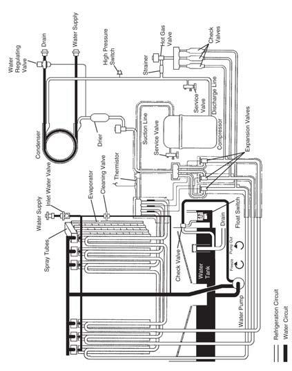
108 KM-2500SWH3 108
109 PERFORMANCE DATA MODEL: KM-61BAH Supply Voltage: 115/60/1 ** Refrigerant: R134A Total Amperage (Compressor RLA): Air: 3.4A (2.29A) Kg=lbs x hours (lbs) Cycle Time Freeze Cycle Time Harvest High Side Water Temp Air Air Air Air
110 PERFORMANCE DATA MODEL: KM-101BAH Supply Voltage: 115/60/1 **Refrigerant: R134A Total Amperage (Compressor RLA): Air: 5.2A (3.39A) Kg=lbs x hours (lbs) Cycle Time Freeze Cycle Time Harvest High Side Water Temp Air Air Air Air
111 PERFORMANCE DATA MODEL: KM-151BAH Supply Voltage: **Refrigerant: R134A Total Amperage (Compressor RLA): Kg=lbs x hours (lbs) Cycle Time Freeze Cycle Time Harvest High Side Air Air Air Air
112 PERFORMANCE DATA MODEL: KM-201B_H Supply Voltage: 115/60/1 Total Amperage (Compressor RLA): Air: 6.1A (5.2A) Water: 6.1A (5.2A) Kg=lbs x hours (lbs) Cycle Time Freeze Cycle Time Harvest High Side Water Temp Air Water Air Water Air Water Air Water
113 PERFORMANCE DATA MODEL: KML-250M_H Supply Voltage: 115/60/1 Kg=lbs x hours (lbs) Cycle Time Freeze Cycle Time Harvest High Side Water Temp Air Water Air Water Air Water Air Water
114 PERFORMANCE DATA MODEL: KM-251B_H Supply Voltage: 115/60/1 Total Amperage (Compressor RLA): Kg=lbs x hours (lbs) Cycle Time Freeze Cycle Time Harvest High Side Water Temp Air Air Air Air
115 PERFORMANCE DATA MODEL: KM-255BAH Supply Voltage: 115/60/1 Total Amperage (Compressor RLA): Kg=lbs x hours (lbs) Cycle Time Freeze Cycle Time Harvest High Side Water Temp Air Air Air Air
116 PERFORMANCE DATA MODEL: KM-260B_H Supply Voltage: 115/60/1 Kg=lbs x hours (lbs) Cycle Time Freeze Cycle Time Harvest High Side Water Temp Air Water Air Water Air Water Air Water
117 PERFORMANCE DATA MODEL: KM-280M_H Supply Voltage: 115/60/1 Total Amperage (Compressor RLA): Air: 11.6A (10.2A) Water: 10A (9.2A) Kg=lbs x hours (lbs) Cycle Time Freeze Cycle Time Harvest High Side Water Temp Air Water Air Water Air Water Air Water
118 PERFORMANCE DATA MODEL: KM-280MAH-E Supply Voltage: /50/1 Total Amperage (Compressor RLA): Air: 5.1A (4.3A) Kg=lbs x hours (lbs) Cycle Time Freeze Cycle Time Harvest High Side Water Temp Air Air Air Air
119 PERFORMANCE DATA MODEL: KM-320M_H Supply Voltage: 115/60/1 Kg=lbs x hours (lbs) Cycle Time Freeze Cycle Time Harvest High Side Water Temp Air Water Air Water Air Water Air Water
120 PERFORMANCE DATA MODEL: KM-320MAH-E Supply Voltage: /50/1 Total Amperage (Compressor RLA): Air: 5.1A (4.3A) Kg=lbs x hours (lbs) Cycle Time Freeze Cycle Time Harvest High Side Air Air Air Air
121 PERFORMANCE DATA MODEL: KML-350M_H Supply Voltage: 115/60/1 Total Amperage (Compressor RLA): Air: 11.5A (11.5A) Water: 10.5A (10.5A) Kg=lbs x hours (lbs) Cycle Time Freeze Cycle Time Harvest High Side Water Temp Air Water Air Water Air Water Air Water
122 PERFORMANCE DATA MODEL: KML-351M_H Supply Voltage: 115/60/1 Total Amperage (Compressor RLA): Air: 13.2A (11.5A) Kg=lbs x hours (lbs) Cycle Time Freeze Cycle Time Harvest High Side Water Temp Air (S-0) 50 / Air Water Air (S-0) Air Water Air (S-0) Air Water Air (S-0) Air Water
123 PERFORMANCE DATA MODEL: KML-450M_H Supply Voltage: 115/60/1 Total Amperage (Compressor RLA): Air: 13.3A (11.6A) Water: 10.6A (10.6A) Kg=lbs x hours (lbs) Cycle Time Freeze Cycle Time Harvest High Side Water Temp Air Water Air Water Air Water Air Water
124 PERFORMANCE DATA MODEL: KML-451M_H Supply Voltage: 115/60/1 Kg=lbs x hours (lbs) Cycle Time Freeze Cycle Time Harvest High Side Water Temp Air Water Air Water Air Water Air Water
125 PERFORMANCE DATA MODEL: KM-461M_H Supply Voltage: 115/60/1 Total Amperage (Compressor RLA): Air: 12A (10.6A) Water: 12.1A (9.4A) Remote: 10.4A (10.4A) Kg=lbs x hours (lbs) Cycle Time Freeze Cycle Time Harvest High Side Water Temp Air Water Remote Air Water Remote Air Water Remote Air Water Remote 50 /
126 PERFORMANCE DATA Supply Voltage: 115/60/1 Total Amperage (Compressor RLA): Air: 13.3A (11.6A) Water: 10 (10A) Kg=lbs x hours (lbs) Cycle Time Freeze Cycle Time Harvest High Side Water Temp Air Water Air Water Air Water Air Water
127 PERFORMANCE DATA MODEL: KM-500MAH-E Supply Voltage: /50/1 Total Amperage (Compressor RLA): Air: 5.5A (5.5A) pcs Kg=lbs x hours (lbs) Cycle Time Freeze Cycle Time Harvest High Side Water Temp Air Air Air Air
128 PERFORMANCE DATA MODEL: KM-501M_H Supply Voltage: 115/60/1 Total Amperage (Compressor RLA): Air: 13A (11A) Water: 10A (10A) Remote: 15A (11A) Kg=lbs x hours (lbs) Cycle Time Freeze Cycle Time Harvest High Side Water Temp Air Water Remote Air Water Remote Air Water Remote Air Water Remote
129 PERFORMANCE DATA MODEL: KM-515M_H Supply Voltage: 115/60/1 Total Amperage (Compressor RLA): Kg=lbs x hours (lbs) Cycle Time Freeze Cycle Time Harvest High Side Water Temp Air Water Remote Air Water Remote Air Water Remote Air Water Remote
130 PERFORMANCE DATA MODEL: KM-515MAH-E Supply Voltage: /50/1 Kg=lbs x hours (lbs) Cycle Time Freeze Cycle Time Harvest High Side Water Temp Air Air Air Air
131 PERFORMANCE DATA MODEL: KM-600MAH Supply Voltage: /60/1 Total Amperage (Compressor RLA): Air: 12A (10.3A) Kg=lbs x hours (lbs) Cycle Time Freeze Cycle Time Harvest High Side Water Temp Air Air Air Air
132 PERFORMANCE DATA MODEL: KML-600M_H Total Amperage (Compressor RLA): Air: 9.5A (9.5A) Remote: 9.5 (9.5A) Kg=lbs x hours (lbs) Cycle Time Freeze Cycle Time Harvest High Side Water Temp Air Water Remote Air Water Remote Air Water Remote Air Water Remote
133 PERFORMANCE DATA MODEL: KML-600MWH Serial L0-M1 Total Amperage (Compressor RLA): Kg=lbs x hours (lbs) Cycle Time Freeze Cycle Time Harvest High Side Water Temp Water Water Water Water
134 PERFORMANCE DATA MODEL: KM-630M_H Total Amperage (Compressor RLA): Water: 6.5A (6A) Remote: 9.5A (6A) Kg=lbs x hours (lbs) Cycle Time Freeze Cycle Time Harvest High Side Water Temp Air Water Remote Air Water Remote Air Water Remote Air Water Remote 50 /
135 PERFORMANCE DATA MODEL: KM-630MAH-E Supply Voltage: /50/1 Total Amperage (Compressor RLA): Kg=lbs x hours (lbs) Cycle Time Freeze Cycle Time Harvest High Side Water Temp Air Air Air Air
136 PERFORMANCE DATA MODEL: KML-631M_H Total Amperage (Compressor RLA): Kg=lbs x hours (lbs) Water Temp Air Water Remote Air Water Remote Air Water Remote Air Water Remote Cycle Time Freeze Cycle Time Harvest High Side
137 PERFORMANCE DATA MODEL: KM-650M_H Total Amperage (Compressor RLA): Air: 6.6A (6A) Water: 5.3A (5.1A) Kg=lbs x hours (lbs) Water Temp Air Water Remote Air Water Remote Air Water Remote Air Water Remote Cycle Time Freeze Cycle Time Harvest High Side
138 PERFORMANCE DATA MODEL: KM-650MAH-E Supply Voltage: /50/1 Total Amperage (Compressor RLA): Kg=lbs x hours (lbs) Cycle Time Freeze Cycle Time Harvest High Side Water Temp Air Air Air Air
139 PERFORMANCE DATA MODEL: KMD-700M_H Total Amperage (Compressor RLA): Air: 13.5A (10.2A) Remote: 13A (10A) Kg=lbs x hours (lbs) Water Temp Air Water Remote Air Water Remote Air Water Remote Air Water Remote Cycle Time Freeze Cycle Time Harvest High Side
140 PERFORMANCE DATA MODEL: KMS-750MLH & SRK-7H 90/32 Kg=lbs x hours (lbs) Cycle Time Freeze Cycle Time Harvest High Side Water Temp
141 PERFORMANCE DATA MODEL: KMD-850M_H Total Amperage (Compressor RLA): Kg=lbs x hours (lbs) Cycle Time Freeze Cycle Time Harvest High Side Water Temp Air Water Remote Air Water Remote Air Water Remote Air Water Remote
142 PERFORMANCE DATA MODEL: KM-900M_H Kg=lbs x hours (lbs) Cycle Time Freeze Cycle Time Harvest High Side Water Temp Air Water Remote Air Water Remote Air Water Remote Air Water Remote
143 PERFORMANCE DATA MODEL: KM-900MRH3 Kg=lbs x hours (lbs) Cycle Time Freeze Cycle Time Harvest High Side Water Temp Remote Remote Remote Remote
144 PERFORMANCE DATA MODEL: KM-900MAH-50 Supply Voltage: /50/1 Total Amperage (Compressor RLA): Kg=lbs x hours (lbs) Cycle Time Freeze Cycle Time Harvest High Side Water Temp Air Air Air Air
145 PERFORMANCE DATA MODEL: KMD-900M_H Total Amperage (Compressor RLA): Air: 15A (11.2A) Water: 14A (11.2A) Remote: 14A (11.2A) Kg=lbs x hours (lbs) Cycle Time Freeze Cycle Time Harvest High Side Water Temp Air Water Remote Air Water Remote Air Water Remote Air Water Remote
146 PERFORMANCE DATA MODEL: KM-901M_H Total Amperage (Compressor RLA): Kg=lbs x hours (lbs) Cycle Time Freeze Cycle Time Harvest High Side Water Temp Air Water Remote Air Water Remote Air Water Remote Air Water Remote
147 PERFORMANCE DATA MODEL: KM-901MRH3 Kg=lbs x hours (lbs) Cycle Time Freeze Cycle Time Harvest High Side Water Temp Remote Remote Remote Remote
148 PERFORMANCE DATA MODEL: KMD-901M_H Total Amperage (Compressor RLA): Kg=lbs x hours (lbs) Cycle Time Freeze Cycle Time Harvest High Side Water Temp Air Water Remote Air Water Remote Air Water Remote Air Water Remote
149 PERFORMANCE DATA MODEL: KMS-1230MLH & SRK-13H Total Amperage (Compressor RLA): 15A (10A) 90/32 Kg=lbs x hours (lbs) Cycle Time Freeze Cycle Time Harvest High Side Water Temp
150 PERFORMANCE DATA MODEL: KM-1300M_H Kg=lbs x hours (lbs) Cycle Time Freeze Cycle Time Harvest High Side Water Temp Air Water Remote Air Water Remote Air Water Remote Air Water Remote
151 PERFORMANCE DATA MODEL: KM-1300S_H Kg=lbs x hours (lbs) Cycle Time Freeze Cycle Time Harvest High Side Water Temp Air Water Remote Air Water Remote Air Water Remote Air Water Remote
152 PERFORMANCE DATA MODEL: KM-1300S_H3 Kg=lbs x hours (lbs) Cycle Time Freeze Cycle Time Harvest High Side Water Temp Air Water Remote Air Water Remote Air Water Remote Air Water Remote
153 PERFORMANCE DATA MODEL: KM-1300SAH-E Supply Voltage: /50/1 Total Amperage (Compressor RLA): Air: 11.5A (10.3A) Kg=lbs x hours (lbs) Cycle Time Freeze Cycle Time Harvest High Side Water Temp Air Air Air Air
154 PERFORMANCE DATA MODEL: KM-1301S_H Total Amperage (Compressor RLA): Kg=lbs x hours (lbs) Cycle Time Freeze Cycle Time Harvest High Side Water Temp Air Water Remote Air Water Remote Air Water Remote Air Water Remote
155 PERFORMANCE DATA MODEL: KM-1301S_H3 Total Amperage (Compressor RLA): Kg=lbs x hours (lbs) Cycle Time Freeze Cycle Time Harvest High Side Water Temp Air Water Remote Air Water Remote Air Water Remote Air Water Remote
156 PERFORMANCE DATA MODEL: KM-1340M_H Kg=lbs x hours (lbs) Cycle Time Freeze Cycle Time Harvest High Side Water Temp Air Water Remote Air Water Remote Air Water Remote Air Water Remote
157 PERFORMANCE DATA MODEL: KMS-1400MLH & SRK-14H Total Amperage (Compressor RLA): 15A (10.3A) 90/32 Kg=lbs x hours (lbs) Cycle Time Freeze Cycle Time Harvest High Side Water Temp
158 PERFORMANCE DATA MODEL: KM-1600MRH 100 / 32 Kg=lbs x hours (lbs) Cycle Time Freeze Cycle Time Harvest High Side Water Temp Remote Remote Remote Remote 50 / 9 50 / 9 50 / 9 50 / 9 50 /
159 PERFORMANCE DATA MODEL: KM-1600MRH3 Total Amperage (Compressor RLA): Remote: 11A (11.4A) Kg=lbs x hours (lbs) Cycle Time Freeze Cycle Time Harvest High Side Water Temp Remote Remote Remote Remote
160 PERFORMANCE DATA MODEL: KM-1600S_H Total Amperage (Compressor RLA): Water: 15A (14A) Remote: 21A (14A) Kg=lbs x hours (lbs) Cycle Time Freeze Cycle Time Harvest High Side Water Temp Water Remote Water Remote Water Remote Water Remote
161 PERFORMANCE DATA MODEL: KM-1600S_H3 Total Amperage (Compressor RLA): Water: 9.5A (9A) Remote: 11A (9.5A) Kg=lbs x hours (lbs) Cycle Time Freeze Cycle Time Harvest High Side Water Temp Water Remote Water Remote Water Remote Water Remote
162 PERFORMANCE DATA MODEL: KM-1601MRH Total Amperage (Compressor RLA): Remote: 11.6A (16.6A) Kg=lbs x hours (lbs) Cycle Time Freeze Cycle Time Harvest High Side Water Temp Remote Remote Remote Remote
163 PERFORMANCE DATA MODEL: KM-1601MRH3 Kg=lbs x hours (lbs) Cycle Time Freeze Cycle Time Harvest High Side Water Temp Remote Remote Remote Remote
164 PERFORMANCE DATA MODEL: KM-1601S_H Total Amperage (Compressor RLA): Kg=lbs x hours (lbs) Cycle Time Freeze Cycle Time Harvest High Side Water Temp Water Remote Water Remote Water Remote Water Remote
165 PERFORMANCE DATA MODEL: KM-1601S_H3 Total Amperage (Compressor RLA): Kg=lbs x hours (lbs) Cycle Time Freeze Cycle Time Harvest High Side Water Temp Water Remote Water Remote Water Remote Water Remote 50 /10 50 /
166 PERFORMANCE DATA MODEL: KM-1800S_H Kg=lbs x hours (lbs) Cycle Time Freeze Cycle Time Harvest High Side Water Temp Air Water Remote Air Water Remote Air Water Remote Air Water Remote
167 PERFORMANCE DATA MODEL: KM-1800S_H3 Kg=lbs x hours (lbs) Cycle Time Freeze Cycle Time Harvest High Side Water Temp Air Water Remote Air Water Remote Air Water Remote Air Water Remote
168 PERFORMANCE DATA MODEL: KM-1900S_H Kg=lbs x hours (lbs) Cycle Time Freeze Cycle Time Harvest High Side Water Temp Air Water Remote Air Water Remote Air Water Remote Air Water Remote 50 /
169 PERFORMANCE DATA MODEL: KM-1900S_H3 Kg=lbs x hours (lbs) Cycle Time Freeze Cycle Time Harvest High Side Water Temp Air Water Remote Air Water Remote Air Water Remote Air Water Remote
170 PERFORMANCE DATA MODEL: KM-2000S_H3 Total Amperage (Compressor RLA): Water: 9.5A (9A) Remote: 12A (9A) Kg=lbs x hours (lbs) Cycle Time Freeze Cycle Time Harvest High Side Water Temp Water Remote Water Remote Water Remote Water Remote
171 PERFORMANCE DATA MODEL: KM-2100S_H3 Total Amperage (Compressor RLA): Water: 10.5A (9A) Remote: 12.5A (9.2A) Kg=lbs x hours (lbs) Cycle Time Freeze Cycle Time Harvest High Side Water Temp Water Remote Water Remote Water Remote Water Remote
172 PERFORMANCE DATA MODEL: KM-2400SRH3 Kg=lbs x hours (lbs) Cycle Time Freeze Cycle Time Harvest High Side Water Temp Remote Remote Remote Remote
173 PERFORMANCE DATA MODEL: KM-2500S_H3 Kg=lbs x hours (lbs) Water Temp Water Remote Water Remote Water Remote Water Remote Cycle Time Freeze Cycle Time Harvest High Side
 115 VAC during harvest for (HGV, etc.")
174 (Brown) 115 VAC to Control Board POWER (Violet) 115 VAC to coil of Magnetic Contactor HARVEST & FREEZE (Brown) (Orange) (Blue) (Red) (Black) (Pink) (Violet) 115 VAC to Control Board 115 VAC to Water Valve 115 VAC to Pump Out Cycle 115 VAC Water Pump during freeze 115 VAC (Line Valve, Fan moter etc.) 115 VAC during harvest for (HGV, etc.) 115 VAC to control board from pin #9 POWER FILL & HARVEST PUMP OUT FREEZE FREEZE HARVEST HARVEST & FREEZE The wiring diagrams on the following pages are generic in some cases because they can represent several models. service manual by model. See the following wiring diagram chart for your model and capacitor information. 174
175 Note: All capacitor values are in MFD Model Wiring Diagram Page Start Capacitor Run Capacitor Pump Capacitor Fan Capacitor Mechanical Bin Control 182 KM-61BAH A 183 None None 1 None KM-101BAH, KM-151BAH A None 1 None KML-250MAH/MWH B ~88 20 None None KML-350MAH/MWH B ~ None None KML-351MAH/MWH Serial S and Before B ~88 20 None 5 KML-351MAH/MWH Serial T and After B ~ None 5 KML-450MAH/MWH B ~ None 5 KML-451MAH/MWH B ~ None 5 KML-600MAH/MWH/MRH, KML-631MAH/MWH B ~ None 5 KM-251BAH/BWH, KM-255BAH/BWH C None
176 Note: All capacitor values are in MFD Model Wiring Diagram Page Start Capacitor Run Capacitor Pump Capacitor Fan Capacitor KM-201BAH, KM-260BAH D None 1 6 KM-280MAH/MWH E ~445 None KM-280MAH-E, KM-500MAH-E F ~ KM-630MAH-E F ~108 None DKM-500BAH Serial UxxxxxA and Before G ~ None 5 DKM-500BAH Serial UxxxxxJ and After G ~ KM-461MRH H ~ KM-501MRH H ~ KM-515MRH H ~ KM-320MAH/MWH I ~ KM-461MAH/MWH I ~ KM-501MAH/MWH I ~
177 Note: All capacitor values are in MFD Model Wiring Diagram Page Start Capacitor Run Capacitor Pump Capacitor Fan Capacitor KM-515MAH/MWH I ~ KM-600MAH J ~ KM-900MRH3, KM-901MRH3 K 193 None None KM-630MAH/MWH L ~ KM-650MAH/MWH L ~ KM-900MAH/MWH L ~ KM-901MAH/MWH L ~ KM-630MRH M ~ KM-650MRH M ~ KM-900MRH M ~ KM-901MRH M ~ KMD-450MAH N/A N/A 243~
178 Note: All capacitor values are in MFD Model Wiring Diagram Page Start Capacitor Run Capacitor Pump Capacitor Fan Capacitor KMD-700MAH/MWH, KMD-850MAH/MWH KMD-700MAH/MWH, KMD-850MAH/MWH N ~ KMD-900MAH/MWH N ~ KMD-700MRH, KMD-850MRH, KMD-901MRH O ~ KMD-900MRH O ~ KMS-750MLH w/srk-7h P ~ KMS-1230MLH w/srk13h, KMS-1400MLH w/srk14h P ~ KMS-1400MLH w/srk-14h(3) Q 199 None None KM-1600SRH3, KM-1600SWH3 R 200 None None KM-1600MRH3, KM-1601MRH3 KM-1300SAH, KM-1300SWH S ~ KM-1300MWH, KM-1340MAH/MWH, KM-1601SWH KM-1600SWH S ~ none 178
179 Note: All capacitor values are in MFD Model Wiring Diagram Page Start Capacitor Run Capacitor Pump Capacitor Fan Capacitor KM-1300SAH3, KM-1300SWH3 T 197 None None 10 5 KM-1300SRH3 U 198 None None KM-1301SAH V ~ KM-1301SWH V ~ None KM-1301SAH3, KM-1301SWH3 Serial U0 and Before W 200 None None 10 5 KM-1301SAH3, KM-1301SWH3 Serial U1 and After X 201 None None 10 5 KM-1301SRH Serial U0 and Before Y ~ KM-1301SRH Serial U1 and After Z ~ KM-1301SRH3 Serial U0 and Before AA 204 None None KM-1301 SRH3 Serial U1 and After BB 205 None None KM-1300SRH, KM-1340MRH, KM-1601SRH, CC ~ KM-1601MRH 179
180 Note: All capacitor values are in MFD Model Wiring Diagram Page Start Capacitor Run Capacitor Pump Capacitor Fan Capacitor KM-1600SRH, KM-1600MRH CC ~ KM-1800SAH, KM-1900SAH, KM-1300MAH DD ~ KM-1900SAH DD ~ KM-1600MRH3/SRH3, KM-1601MRH3/SRH3 EE 213 None None KM-1800SWH3/SRH3, KM-1900SWH3/SRH3 KM-2000SWH3/SRH3 KM-1800SWH, KM-1800SRH FF ~ MFD KM-1900SWH, KM-1900SRH FF ~ MFD KM-1800SAH3, KM-1900SAH3 GG 215 None None 10 5 KM-2000SWH3/SRH3, KM-2100SWH3/SRH3 HH 216 None None KM-2400SRH3, HH 216 None None
181 KM Wiring Diagram Reference Chart Note: All capacitor values are in MFD Model Wiring Diagram Page Start Capacitor Run Capacitor Pump Capacitor Fan Capacitor URC-5F/6F/7F/9F 10 URC-12F/14F/20F/21F/22F/23F (2 FANCAPS) 10 URC-24F (4 FANCAPS) 15 SRC-10H 189~ SRK-7H (2 FANCAPS) 145~ SRK-13H/14H (2 FANCAPS) 145~ SRK-14H3 (2 FANCAPS)
182 MECHANICAL BIN CONTOL OPERATION: The mechanical bin control is included on some models. The mechanical assembly is located in the ice drop zone area. When the actuator paddle is in the normal (Bin Empty) position, the bin control proximity switch will close. On E board models, 1. When the switch contacts close, 7.6 K Ohms of resistance is supplied to the K4 board connector. 2. When ice pushes the paddle to the full right position (Bin Full), the proximity switch opens as shown aboveand will supply 15.8 K Ohms to the K4 board connector. For G Board models, resistors are not used. The switch will close to start the unit and open to stop the unit. 182
183 A KM-61BAH, KM-101BAH, KM-151BAH Note: 1. KM-61BAH uses PTC Relay for compressor. 2. switch used on KM-151BAH model only. Cut-out: 355+/-21 psig Cut-in: 270+/-21 psig 3. See wiring diagram chart for capacitor ratings. 183
184 B KML-250MAH/MWH, KML-350MAH/MWH, KML-351MAH/MWH, KML-450MAH/MWH, KML-451MAH/MWH, See Page 293 for these 208/230V models... KML-631MAH/MWH,KML-600MAH/MWH/MRH Note: 1. Some models use mechanical bin control instead of thermostatic bin control with fuse as shown. 2. Generic Diagram: See unit service manual or wiring diagram chart for capacitor ratings by model /230V KML-600/630M models are located on page
185 C KM-251BAH/BWH, KM-255BAH/BWH 185
186 D KM-201BAH, KM-260BAH /09
187 E KM-280MAH/MWH Note: 1. Some models use mechanical bin control instead of thermostatic bin control with fuse as shown. 2. Generic Diagram: See unit service manual or wiring diagram chart for capacitor ratings by model. 187
188 F KM-280MAH-E, KM-500MAH-E, KM-630MAH-E Note: 1. Some models use mechanical bin control instead of thermostatic bin control with fuse as shown. 2. Generic Diagram: See unit service manual or wiring diagram chart for capacitor ratings by model. 188
189 G DKM-500BAH 189
190 H KM-461MRH, KM-501MRH, KM-515MRH NOTE: Generic diagram: See unit service manual or wiring diagram chart for capacitor ratings by model. 190
191 I KM-320MAH/MWH, KM-461MAH/MWH, KM-501MAH/MWH, KM-515MAH/MWH NOTE: 1.Generic diagram: See unit, service manual, or wiring diagram chart for capacitor ratings by model. 2.Production of KM-320/515M after February 09 uses G board and mechanical bin control with no resistors in wiring harness. 191
192 J KM-600MAH 192
193 K KM-900MRH3, KM-901MRH3 Note: 1. Some models use thermostatic bin control with fuse instead of mechanical bin control as shown. 2. Production after February 09 uses G board and mech bin control with no resistors in wiring harness. 193
194 L KM-630MAH/MWH, KM-650MAH/MWH, KM-900MAH/MWH, KM-901MAH/MWH Note: 1. Some production models will include thermostatic bin control with fuse instead of mechanical bin control as shown. 2. Generic diagram: See unit, service manual or wiring diagram chart for capacitor ratings by model. 3. Production after February 09 uses G board and mechanical bin control with no resistors in wiring harness. 194
195 M KM-630MRH, KM-650MRH, KM-900MRH, KM-901MRH Note: 1. Generic diagram: See unit, service manual or wiring diagram for capacitor ratings by model. 2. Some production medels will include mech BC instead of thermostiatic BC. 3. Later production after February 09 uses G board and mech BC with no resistors in wiring harness. 4. KM-900MRH before M2 have different numbering on contactor but wiring remains the same. 195
196 N KMD-700MAH/MWH, KMD-850MAH/MWH, KMD-900MAH/MWH, KMD-901MAH/MWH Note: 1. Generic diagram: See unit, service manual, wiring diagram chart for capacitor ratings by model. 2. Line valve only used on KMD-901M 3. KMD-700/900M use E board and resistor wiring harness. 196
197 O KMD-700MRH, KMD-850MRH, KMD-900MRH, KMD-901MRH Note: 1. Generic diagram: see unit, service manual, wiring diagram chart for capacitor ratings by model. 2. KMD-700/900M use E board and resistor wiring harness. 197
198 P KMS-750MLH w/srk-7h, KMS-1230MLH w/srk13h, KMS-1400MLH w/srk-14h Note: Generic diagram: See unit, service manual wiring diagram chart for capacitor ratings by model. 198
199 Q KMS-1400MLH w/srk-14h(3) 199
200 R KM-1600SRH3, KM-1600SWH3, KM-1600MRH3, KM-1601MRH3 200
201 S KM-1300SAH, KM-1300SWH, KM-1300MWH, KM-1340MAH/MWH, KM-1600SWH, KM-1601SWH 201
202 T KM-1300SAH3, KM-1300SWH3 202
203 U KM-1300SRH3 203
204 V KM-1301 SAH, KM-1301SWH Note: SWH does NOT include fan. 204
205 W KM-1301SAH3, KM-1301SWH3 Serial Code: U0 and before 205
206 X KM-1301SAH3, KM-1301SWH3 Serial Code: U1 and after * Transformer Output 10.5V at 115V 206
207 Y KM-1301SRH 207
208 Z KM-1301SRH Serial Code: U1 and after * Transformer Output 10.5V at 115V 208
209 AA KM-1301SRH3 Serial Code: U0 and before 209
210 BB KM-1301SRH3 Serial Code: U1 and after * Transformer Output 10.5V at 115V 210
211 CC KM-1300SRH, KM-1340MRH, KM-1600SRH, KM-1600MRH, KM-1601SRH, KM-1601MRH 211
212 DD KM-1800SAH, KM-1900SAH, KM-1300MAH 212
213 EE KM-1600MRH3/SRH3, KM-1601MRH3/SRH3, KM-1800SWH3/SRH3, KM-1900SWH3/SRH3, KM-2000SWH3/SRH3 213
214 FF KM-1800SWH, KM-1800SRH, KM-1900SWH, KM-1900 SRH 214
215 GG KM-1800SAH3, KM-1900SAH3 215
216 HH KM-2000SWH3/SRH3, KM-2100SWH3/SRH3, KM-2400SRH3, KM-2500SRH3 216
217 Flaker/DCM General Installation As always, you should follow the installation instructions that are provided in the instruction manual supplied with the unit. Three things are critical for a proper F/DCM installation: 1. The water temperature should fall within the 45 F to 90 F range. Note: Colder water can cause excess stress on the auger gear motor which may activate the gear motor overload. areas as high mineral content can cause premature bearing wear, poor production, and ineffecient operation. 3. The unit should be level, front to back, side to side to assure proper evaporator water level and maximum production. This is neccessary because of the gravity feed water distribution. Cubelet Models the extruding head and cutter at the top of the evaporator assembly and in most cases, an evaporator barrel heater. are designated by a -C at the end of the model number. production by around 8~10%. This drop in production is due to the compacting of the ice in the extruding head. The ducing cubelet ice with only a slight increase in the running amperage. The evaporator outlet temperature and operating the temperature and pressure information provided on the when diagnosing a converted cubelet (-C) unit. 217
218 Internal Auger Design Hoshizaki Flakers and DCM s use an internal auger system evaporator cylinder and auger are made of anti-magnetic pitting caused by harmful minerals in the water. This The picture below is a generic breakdown of the F/DCM evaporator assembly. The extruding head #9 and cutter #12 can be exchanged so that this Flaker assembly will produce Cubelet style (chunklet) ice like the DCM application. The sleeve type alignment bearings are pressed into the housing #4 and extruding head #9. The mechanical seal #6 and O ring #5 seal the lower end of the evaporator system. 218
219 Component Technical Data Control Transformer Hoshizaki Flaker units include a 24 volt control transformer. This transformer has a 115 volt primary and 24 volt secondary and is protected by a 1 amp control fuse (The DCM has a dual output secondary of 10.5V to terminals K4-1 & 2 with a 0.5A fuse and 24V on terminals K2-7 & 2 with a 1A fuse). The 24 volt secondary supplies power to: the solid state timer to convert to 24VDC. Without control voltage on pins 1 and 2, the timer board will not allow the unit to start. Gear Motor Protection The auger gear motor circuit includes two overload safeties. The primary safety is a manual reset, current type protector, or slow blow fuse located in the control box. This is a time delay protection which operates if high amp draw occurs. The secondary safety is a thermal protector incorporated into the gear motor windings. The current type gear motor safety has been replaced with a slow blow fuse on most models. The fuse provides more consistant protection in low voltage applications and the correct fuse type and amprage must be used. Gear Motor Protection Model F-330B, DCM-270/750B F-450M_H, DCM-500B F-800M_H F -801/1001M_H(-C), FD-1001MAH-C F-1500M_H F-2000M_H Protection Current type protector 2 amp fuse 1.5 amp fuse 3 amp fuse. 7 amp fuse 10 amp circuit protector 7 amp fuse 10 amp circuit protector Gear motor failure can be expensive and it is very important are several possibilities for the cause of gear motor failure. your failure occurred. 219
220 Gear Motor Checkout 1. Normal Amperage: The amperage for gear motor should to discover the possible cause for your failure: 1. Is Ambient Temperature above 45 degrees F. 2. Does the unit have the Wrong Extruding Head. Check the Extruder Type. Is it a Flaker or Cubelet style. (The cubelet style head will have smaller openings for the ice to extrude.) 3. Does the unit have the Wrong Cutter. The cutter should match the extruding head style. Flake or Cubelet. 4. Do you have a Damaged Extruder. Look for following imperfections. A. Dents B. Fins Bent C. Scale D. Other Resistance Note: A dirty, or scaled up, evaporator can cause the gear motor fuse to blow. 5. Does the unit have the Correct Auger. Is the auger breakdown for the correct auger style. 6. Check the Voltage Supply and circuit amperage. Is this should be within +/- 10% of the rated voltage when the unit is making ice. 7. Check the Running Voltage at the gear motor. (While the unit is making Ice.) 8. Inspect bearings for wear. ( Use bearing gauge ) both bearings should be replaced. 9. Check Evaporator Cylinder/ Barrel for signs of scoring.10. Is there any condensation dripping onto the action to stop the moisture. 11. Is the galvanized shield mounted over the motor 12. Verify that you have the proper Gear Motor Capacitor. 13. Is the Gear Motor Locked. Check motor winding resistance. 2. Wrong Gear Motor Overload/Fuse: Check fuse size. Has the original overload reset been replaced with the wrong size ing it with a standard fuse will cause the fuse to blow again. Note: Although it is common practice to install a larger fuse during service diagnosis, you should not leave a larger fuse in the unit when you leave the site. This could cause a seri- 220
221 Note: You should never jumper the fuse protector! 3. Miswiring Is gear motor wired correctly and wire connections tight. Check the wiring diagram for the proper wiring. 4. Bin Control Switch Does Not Operate Check the bin control operation. A bad or miswired bin control can cause ice to back up in the spout and chute and cause higher gear motor amperage. Is Bin Control wired correctly Make sure there are no metallic components interfering with the magnetic bin control. Verify top panel is non-magnetic. Assure that the proximity switch is mounted properly. The switch must be secure and mounted level to the chute top. Does the Bin Control Paddle move freely and is it Gear Motor Stress As you can see, there are many factors that can cause a gear motor to fail. Every effort should be made to determine the cause for a gear motor failure when the gear motor is replaced. When looking for the cause of a gear motor failure, you should consider anything that will add stress to the assembly. Stress on the gear motor will increase the gear stress is scale on the auger surface and evaporator walls. Scale insulates the evaporator walls and causes reduced heat transfer. As a result, the ice will be wet and mushy. in the evaporator outlet and extruding head. Heavy scale build up must be removed using an acid based cleaner which will loosen the scale. Follow the cleaning instructions provided on the cleaning label to preform a maintenance cleaning. If the unit has not been cleaned and and clean the cylinder wall with a Scotchbrite pad & cleaner. The extruding head surface may also have heavy scale and can be cleaned with Scotchbrite & cleaner as well. Loose bolts on the gear motor, housing, and extruding head can also cause stress. Always check to assure they are secure when conducting preventative maintenance. 221
222 Auger Bearings Bearing Type: Sleeve/Alignment, Bearing Material: Poly/Carbon The bearings are pressed into the top extruding head and lower brass housing. A repress program is available through the local Hoshizaki Distributor for undamaged extruding heads and housings. The bearings should always be replaced as a set. Return the extruding head and housing to your distributor for an exchange set or to be returned for repressing. Bearing Inspections It is important to remember that bearings are a wear item. Annual bearing inspections are recommended. More fre- areas. The steps for bearing inspections are as follows: (1 ) Gain access to the ice chute head by removing the top panel and spout connectors as necessary. Use warm water to melt any ice in the evaporator if necessary. (2) Remove the thumbnuts which hold the ice chute head in place and lift it up and off of the evaporator (take care to place the O-ring in a safe location until you replace the head.) (3) Remove the stainless steel bolt holding the cutter or breaker in place and lift off to access the extruding head and auger shaft. (4) Replace the bolt into the auger shaft and use it to push the auger back and forth from left to right to check for excessive movement. (5) Pull the auger towards you and try to insert a.02 round stock or pin gauge in between the back side of the auger shaft and bearing surface. Check several locations around the auger shaft. If the gauge will go in between the shaft and bearing surfaces, it is time to install new bearings. Both top and bottom bearings should be replaced if the top bearing is worn. If there is no excessive movement in the auger shaft and the gauge does not chute head and connectors. Auger Inspection / Bearing Replacement A visual inspection of the auger bearing shaft surface is also 222
223 recommended annually in poor water areas. The steps for this inspection is as follows: Note: evaporator system following the instructions located on the Inside front panel, before you attempt to remove the auger. (1) Follow steps 1 through 5 of the bearing inspection procedure above. (2) Remove the (metric) Allen head cap screws with seals that secure the extruding head in place. (3) Thoroughly drain the water supply system. (4) Turn the cutter up-side down, replace the bolt and use the cutter to lift the auger out of the evaporator. (5) With the auger removed, remove the cutter and slide the extruding head from the top of the auger. Visually inspect the bearing surface at the top and bottom of the auger. damage. The extruding head contains the top bearing, the bottom bearing is pressed into the brass housing at the bottom of the evaporator. To remove the housing: (6) To remove the housing: Remove the Allen screws that secure the evaporator to the housing. (7) Loosen the belly band screw and lift the evaporator up and off of the housing. Holding the evaporator up, retighten the belly band. This will hold the evaporator up so that you can remove the housing. (8) Remove the bolts that secure the housing to the gear motor assembly and remove the housing. The mechanical seal, ceramic disk and boot are pressed into the top of the housing. Remove these parts before you exchange the bearings. Exchange the extruding head and housing for a repressed set at your local distributor To replace the new parts, reverse the order above. Use a light coat of food grade silicone lubricant around the inside bottom of the evaporator and on the o-ring to and help keep it in place as you lower the evaporator. Note: Do not use mineral oil as it can damage the o-ring material. 223
224 Inspect the mechanical seal thoroughly and reuse it, if it is in good shape. Take care not to get oil or dirt on the seal surfaces. When replacing the bolts holding the extruding head, a good seal is important. Replace the bolts and seals if a damaged checked during each preventative maintenance check, as severe temperature changes can loosen them. The seal between the drain pan and top of the evaporator is also important. Do not pull upwards on the evaporator drain pan. If seal is broken, reseal with silicone. Flaker Safety s Mechanical failures in an auger style ice machine can be time consuming and expensive repairs. Hoshizaki has incorporated several safety s in our Flaker and DCM units which add protection against this type of failure. The following safety s are included in all Hoshizaki F and DCM units: 1. Low water safety: Designed to protect against dry operation or possible freeze up in the evaporator due to and a 90 second timer to shut down the unit when water 2. Protect relay safety: This safety incorporates a relay in the gear motor circuit and will not allow the refrigeration system to operate unless the gear motor is running. If the gear motor fails during normal operation, the protect relay shuts down the compressor to protect against evaporator freeze-up. 3. Gear motor circuit safety s: The gear motor has 2 additional safety s which will operate if the gear motor is subjected to excessive load or improper voltage. A current type manual reset safety or slow blow fuse is located in the control box and will trip when the gear motor amperage exceeds normal amp draw. This acts as a primary safety for the gear motor. A secondary internal thermal overload is included in the motor windings. Both will work in conjunction with the protect relay to shut the unit down. The gear motor current protector serves as a back-up for the bin control on other models. These safety s protect the Flaker or DCM models from internal failures. 224
225 4. Voltage protect relay: This relay will shut the unit off in case of a voltage surge and automatically restart the unit when the voltage is correct. 5. High pressure switch: All Hoshizaki ice machines include an automatic reset high pressure safety switch to shut down the unit in case of high head pressures. 6. Fuse protection: A lamp buss-type fuse is utilized in the control circuit. Smaller units like the DCM-240 and F-300 have a fuse in the incoming power circuit. 7. Short cycle protection timer: A 1 minute time delay short cycling the gear motor or compressor. Note: The FD has a 5 minute time delay. 8. Compressor protection is provided either internally or by means of an external motor circuit protector. This is an automatic reset thermal type circuit breaker. 9. Some F-1500/2000 have a spout safety control to shut down the unit if the bin control fails for any reason. This is a manual reset safety and will notify the technician by means of a indicator light on the control box. To reset this safety, turn the control switch OFF and back ON. This re-sets the holding relay circuit and turns off the light. Note: This feature was removed from F-1500/2000M in late 2009 production and after. Dual Float Switch as a universal replacement on any Hoshizaki Flaker or DCM is susceptible to scale build-up. The amount of scale build-up and checked. Soak the switch assembly in ice machine cleaner. While it is 225
226 from the shaft during cleaning. If you remove them, note that tion. Once clean, rinse and wipe the cleaner off and check and two separate switches. Check the top switch by ohming should be closed. Check the bottom switch by ohming out Dual Float Switch Drawing 226
227 Flaker Water Fill System Standard Timer Board Models The reservoir in a Hoshizaki auger type ice maker feeds water in the reservoir is maintained by the operation of the switches inside of a sealed shaft. The reed switch contacts are operated by individual magnets attached inside the top As ice is made and extruded from the evaporator cylinder, the water level in the reservoir drops. When the level drops, the control of the water control relay in the control circuit. As the to de-energize the water control relay. De-energizing the water control relay closes a circuit to supply 24 volts to the inlet water valve solenoid. This allows water (terminals 3 & 4) which starts a 90 second low water safety shutdown timer. the reservoir level rises, these two switches swap jobs. The energizes the water control relay. This will stop the safety or the water supply is turned off, the unit cycles down and the water valve remains energized. This same action occurs if the inlet water valve fails. When the water supply is restored, water control relay to automatically restart the unit. This system provides a consistent water level in the reservoir and evaporator as well as providing an automatic reset low water safety protection. is susceptible to scale build-up. The amount of scale build-up and checked. 227
228 Flaker Timer Board This standard solid state timer board part # , is used on all F-models and the DCM-270BAH model. It is a simple electronic sequence timer. In order for the board to sequence, certain circuits must be closed. In order to diagnose a bad timer board, it is necessary to check these circuits to assure they are operating properly. If you are trouble-shooting a transformer. The output of this transformer is protected by a 1 amp buss type fuse. Control voltage comes in the timer board on pins 1 & 2. If you do not have 24 volts at pins 1 & 2, check the transformer and fuse. may be 120V) across pins 8 & 2. If voltage is present, the timer board has cycled up to energize the gear motor circuit which indicates there is not a problem in the timer board. The problem may be in the gear motor relay circuit. Remember that there is a time delay from the time you turn the unit on to the time it cycles up completely. This time will be from 1 ~ 2.5 minutes, depending on the unit model. circuit to pins 3 & 4. Do not confuse these pins with the line voltage terminals marked 3 & 4 on the compressor relay located on the board. You can check this circuit with a volt meter across the pins or by placing a jumper across them. If the unit cycles up with the jumper in place, the board is good and your problem is in the water relay control circuit. Note: In self contained models, the bin control will be in series with terminals 3 & 4. Check the bin control operation if this circuit is open and the water control relay is closed. Next, you should check the bin control circuit at pins 5 & 6. Check for a closed circuit with a volt meter or place a jumper across them. If the unit cycles up with the jumper in place, the board is good and the bin control circuit is the problem. The last circuit check is across pins 10 & 11. These pins connect to the gear motor protect relay and will shut down the unit if the gear motor fails. Check for a closed circuit with a volt meter or place a jumper across them. If the unit cycles up with the jumper in place, the board is good and the gear motor protect circuit is suspect. 228
229 Flaker Sequence of Operation board to switch the components on and off as needed. This timers within the solid state timer board. With proper voltage and water supplied to the Flaker and the the inlet water valve. The unit will not start unless the reservoir the up position). The operation is then turned over to the bin control. If the bin control is closed and calling for ice, the gear motor and condenser fan motor are energized. One minute later, the compressor starts. As the refrigeration systems cools the water in the evaporator, ice will start to form within 2 to 5 minutes. This depends on the inlet water temperature and ambient conditions. Ice production will continue until the simple. On the F-450/801/1001/1500/2000 units, the entire unit shuts down within 6 seconds after the bin control switch opens. On the F-330, 90 seconds after the bin control switch opens, the compressor and fan motor stops, one minute later the gear motor stops. Flaker Periodic Flush complete water system to drain. The unit will remain off for 15 minutes which allows any ice remaining in the evaporator period. The unit will automatically restart after 15 minutes FD Flush On the FD control board, the unit does not shut down to 1. The drain valve will open for 2 seconds every hour and the unit continues to operate. 2. Every 12 hrs. the unit will cycle down and allow for a 10 minute drain cycle. Either option can be selected by a dip switch adjustment. 229
230 Flaker Sequence Flow Chart (Standard timer) 230
231 Flush/Low Water Safety Flow Chart (Standard timer) 231
232 New FD Control Board The FD-1001MAH-C unit has a new control board design. The design incorporates the necessary circuitry for use on the DCM models at a later date. For now, it is utilized on the FD-1001MAH-C model only. It has additional safeties, longer delay timers, audible alarms and dip switch adjust- The control board part number is 2A The following alarms are included. The alarm will repeat every 5 seconds until reset. **To reset the manual alarms, turn the power OFF and Back ON Beep - Low Water Safety This alarm will occur if water supply is interrupted. It will automatically reset when water supply is restored Beep - Control Switch in DRAIN position This alarm will occur if control switch is left in the DRAIN position for more than 15 minutes. It will automatically reset when control switch is moved to ICE or 4 Beep - High Alarm a. A 3 beep alarm will occur if HP switch activates shut down and alarm will automatically reset when HP switch closes. b. A 4 beep alarm will occur if HP switch activates third time in 1 hour. The machine will shut down and must be manually reset. The high pressure issue must be resolved in this case Beep Freeze Timer Alarm This alarm will occur The machine will shut down and must be manually 5. 6 Beep Low Voltage Alarm If supply control voltage drops to 92 volts +/- 5% unit will shut down to protect the components and Power OK LED will turn off. Alarm will automatically reset when voltage corrects. 232

233 6. 7 Beep High Voltage Alarm If control voltage reaches 142 volts +/- 5% unit will shut down to protect the components and Power OK LED will turn off. Alarm will automatically reset when voltage corrects Beeps Gear Motor Alarm Occurs if gear motor-protect relay circuit operates, compressor and gear motor will stop. Manually reset after checking gear motor circuit Beeps Bin Control Alarm Occurs if unit shuts down on bin spout control and infrared sensor is calling for ice. Manually reset and check infrared bin control operation. Adjustable dip switches are provided on this control board. tion. This control board will be used for other models at a later date. They function as follows: For the FD unit application, the factory setting is switches 1~7 OFF, 8 ON, 9 &10 OFF. These dip switches should remain in the factory setting for proper operation of this model. 233
234 FD Board S1 Dip Switch Adjustment Chart Dip switch Delay Timer Setting OFF OFF OFF 0 Seconds ON OFF OFF 100 Seconds (1.6 minutes) OFF ON OFF 1100 Seconds (18.3 minutes) OFF OFF ON 1650 Seconds (27.5 minutes) ON ON OFF 2200 Seconds (36.7 minutes) OFF ON ON 0 Seconds ON ON ON 0 Seconds 4 Drain Timer Interval Drain Valve Open OFF 1hr 2 secs ON 11 hrs 36 min 10 mins 5 6 Dispense Time (DCM s ONLY) OFF OFF No limit ON OFF 20 Seconds OFF ON 60 Seconds ON ON No Limit 7 Bin Control Application OFF Mechanical Spout Safety Switch Only ON Mechanical Spout Safety Switch and Infrared Sensor 8 Mechanical Spout Safety Shutdown Delay OFF 0.25 Seconds ON 6.7 seconds **See FD service manual for more details on sequence of operation and service diagnosis of the FD board and product. 234
235 FD Control Board Drawing This pictorial will allow you to locate the board componant locations. Since this is a new board, it will help you become more familure with the board. You will see this board used FD Sequence Chart Sequence Step LED 1. Fill Cycle Power OK, WTRIN (Water in) 2. Ice Purge Cycle Power OK, GM 3. Freeze Cycle Power OK, GM, COMP, 4. Drain Cycle Power OK, DRAIN Step Energized Components Min Max 1. WV 2. GM, FMS, FMR, LLV 5 min. 5 min. 3. GM, COMP, FMS, FMR, LLV WV* * 20 sec. * 90 sec. 4. DV (S1 Dip Switch 4)>> 2 sec. 10 min. 235
236 FD Bin Control #2 (infrared sensor) Sequence Flow Chart and Operation Note: When proximity switch bin control is used, step 2 does NOT include 30 sec gear motor delay. 236
237 FD Bin Control #2 (infrared sensor) Sequence Flow Chart and Operation (continued) Note: When proximity switch bin control is used unit shuts down in 6 seconds and restarts when ice level drops away from control paddle. 237
238 DCM Sequence of Operation with a delay of the compressor at start up and a delay of the gear motor at shut down. DCM models have periodic agitation in the bin to eliminate ice bridging. The DCM-270 model uses a solid state relay to turn the gear motor for.2 seconds every 90 minutes. On DCM-500 /750B models, the solid state timer board will start the agitation motor for.6 seconds every 12 seconds of accumulated operation can be found in the unit service manual. Note: The DT-400BAH-0S is a new dispenser model. The refrigeration system is mounted in the bottom of the unit and the dispenser is on top. This allows a DCM type dispenser that is 22.5 wide and 72.5 tall. The operation will be the same as a standard DCM-500B. A replacement refrigeration system DT-400-AR is available for this model. Flaker/DCM Production Check Performing a production check is an excellent way to prove proper F/DCM operation. Checking the production on these models is a simple process. To check the production you will need a small trash bag, bucket or pan to catch the ice and a set of scales to weigh the ice. For best results, you should always check production on a unit that has a cold evaporator. After the unit has operated for 10 to 20 minutes, catch the ice production directly from the evaporator for 10 full minutes. Weigh the ice to establish the batch weight. Multiply the batch weight by 144 for the total production in 24 hours. Some prefer to catch the ice for 20 minutes and multiply the weight by 72 for a more realistic production check. It is true that a longer catch is more accurate however, it doubles your test time and may only show a 1 to 2% difference in total production. Once you know the 24 hour production, check it against the on the preformance data chart. If the production is within +/- 10% iof the data on the chart, it is OK. 238
239 DCM-500/750B_H Timer Board This timer board allows the DCM to operate as per the se- The DCM 500/750B_H timer board includes the following safeties: A. Low Water Safety - Automatic shutdown and restart if water supply is interrupted. B. Ice Purge - Allows gear motor delay to remove ice from the evaporator during shut down. C. Short Cycle protection for the compressor - Delays restart of compressor if unit is switched off and on or if power is interrupted. D. Power LED - Indicates control voltage is available. *Flush switch MUST remain in the P position. *The portion control adjustment is set from the fatory at 0.6 mately 1.2 oz of ice dispensed. 239
240 DCM-500/750B_H Timer Board Flow Chart 240

241 DCM-500/750B_H-OS Timer Board Flow Chart (continued) 241
242 Flaker/DCM Water/Refrigeration Circuit Drawing Reference List MODEL DRAWING PAGE DCM-270BAH-OS...A DCM-500BAH/BWH-OS DCM-750BAH/BWH...B DT-400BAH-OS...C F-330BAH...D F-450MAH, F-800MAH/MWH, F-801MAH/MWH, F-1001MAH/MWH, FD-1001MAH/MWH, F-1500MAH/MWH.E F-1001MRH, FD-1001MRH-C, F-1500MRH...F F-1001MLH...G FS-1001MLH-C...H SRC-10H...H F-2000MRH...I F-2000MLH...J NOTE: Some drawings have been combined to represent more than one model. 242
243 A DCM-270BAH-OS 243
244 B DCM-500BAH/BWH-OS DCM-750BAH/BWH-OS Inlet Spout Water Supply Valve Compressor Valve Refrigeration Circuit Water Circuit Water Su Water Supp Wat Valv 244
245 C DT-400BAH-OS Wate 245
246 D F-330BAH 246

247 E F-450MAH, F-800MAH/MWH, F-801MAH/MWH, F-1001MAH/MWH, FD-1001MAH/MWH-C, F-1500MAH/MWH 247
Hoshizaki America, Inc.
 Hoshizaki America, Inc. Stackable Crescent Cuber Models KM-1800SAH/3 KM-1800SWH/3 KM-1800SRH/3 A Superior Degree of Reliability SERVICE MANUAL www.hoshizaki.com Number: 73131 Issued: 11-11-2005 Revised:
TECH - SPEC S Technician s Pocket Guide # 80045
 TECH - SPEC S Technician s Pocket Guide # 80045 This technicians pocket guide covers all models using R-404A refrigerant. For additional technical information, full parts and service manuals are available
Hoshizaki America, Inc.
 Hoshizaki America, Inc. Low-Profile Modular Crescent Cuber Models KML-631MAH KML-631MWH KML-631MRH A Superior Degree of Reliability SERVICE MANUAL www.hoshizaki.com Number: 73150 Issued: 5-9-2007 Revised:
Hoshizaki America, Inc.
 Hoshizaki America, Inc. Modular Crescent Cuber Models KMD-901MAH KMD-901MWH KMD-901MRH A Superior Degree of Reliability SERVICE MANUAL www.hoshizaki.com Number: 73154 Issued: 3-28-2008 IMPORTANT Only qualified
IMPORTANT. HOSHIZAKI provides this manual primarily to assist qualified service technicians in the service and maintenance of the icemaker.
 73105 IMPORTANT Only qualified service technicians should attempt to service or maintain this icemaker. No service or maintenance should be undertaken until the technician has thoroughly read this Service
Hoshizaki America, Inc.
 Hoshizaki America, Inc. Stackable Crescent Cuber Models KM-1601SAH/3 KM-1601SWH/3 KM-1601SRH/3 A Superior Degree of Reliability SERVICE MANUAL www.hoshizaki.com Number: 73145 Issued: 10-31-2006 Revised:
Hoshizaki America, Inc.
 Hoshizaki America, Inc. Modular Crescent Cuber Models KMD-850MAH KMD-850MWH KMD-850MRH A Superior Degree of Reliability SERVICE MANUAL www.hoshizaki.com Number: 73163 Issued: 9-3-2008 Revised: 1-9-2014
Hoshizaki America, Inc.
 Hoshizaki America, Inc. Low-Profile Modular Crescent Cuber Models KML-351MAH KML-351MWH A Superior Degree of Reliability SERVICE MANUAL www.hoshizaki.com Number: 73149 Issued: 6-10-2008 IMPORTANT Only
Hoshizaki America, Inc.
 Hoshizaki America, Inc. Stackable Crescent Cuber Models KM-1900SAH/3 KM-1900SWH/3 KM-1900SRH/3 A Superior Degree of Reliability SERVICE MANUAL www.hoshizaki.com Number: 73171 Issued: 2-9-2009 Revised:
KM-630MAH KM-630MWH KM-630MRH
 NO.: ISSUED: 73114 JUNE 23, 2004 HOSHIZAKI MODULAR CRESCENT CUBER MODEL KM-630MAH KM-630MWH KM-630MRH SERVICE MANUAL IMPORTANT Only qualified service technicians should attempt to service or maintain this
Hoshizaki America, Inc.
 Hoshizaki America, Inc. Modular Crescent Cuber Models KM-515MAH KM-515MWH KM-515MRH A Superior Degree of Reliability SERVICE MANUAL www.hoshizaki.com 1 Number: 73157 Issued: 2-1-2008 IMPORTANT Only qualified
KM-61BAH KM-101BAH KM-151BAH
 NO. M006-749 ISSUED: FEB. 18, 2008 REVISED: JUN. 12, 2008 HOSHIZAKI SELF-CONTAINED CRESCENT CUBER MODEL KM-61BAH KM-101BAH KM-151BAH SERVICE MANUAL IMPORTANT Only qualified service technicians should attempt
Reliability is a beautiful thing TM MODULAR CRESCENT CUBER KM-500MAH KM-500MWH KM-500MRH SERVICE MANUAL
 Reliability is a beautiful thing TM MODULAR CRESCENT CUBER KM-500MAH KM-500MWH KM-500MRH SERVICE MANUAL NUMBER: 73104 ISSUED: NOV. 7, 2002 REVISED: DEC. 16, 2003 IMPORTANT Only qualified service technicians
Hoshizaki America, Inc.
 Hoshizaki America, Inc. Modular Crescent Cuber Serenity Series Model KMS-1400MLH Including Condensing Unit Model SRK-14H/3 A Superior Degree of Reliability SERVICE MANUAL www.hoshizaki.com Number: 73162
Hoshizaki America, Inc.
 Hoshizaki America, Inc. Modular Crescent Cuber Serenity Series Model KMS-822MLH Including Condensing Unit Model SRK-10H A Superior Degree of Reliability SERVICE MANUAL www.hoshizaki.com Number: 73182 Issued:
Hoshizaki America, Inc.
 Hoshizaki America, Inc. Modular Flaker Models FD-1001MAH(-C) FD-1001MWH(-C) FD-1001MRH(-C) FD-1001MLH(-C) A Superior Degree of Reliability INSTRUCTION MANUAL www.hoshizaki.com Issued: 4-24-2009 Revised:
Hoshizaki America, Inc.
 Hoshizaki America, Inc. Low-Profile Modular Crescent Cuber Models KML-451MAH KML-451MWH A Superior Degree of Reliability SERVICE MANUAL www.hoshizaki.com Number: 73143 Issued: 3-1-2007 IMPORTANT Only qualified
Hoshizaki America, Inc.
 Hoshizaki America, Inc. Modular Crescent Cuber Serenity Series Model KMS-830MLH Including Condensing Unit Models SRK-8H/3 A Superior Degree of Reliability SERVICE MANUAL www.hoshizaki.com Number: 73185
Hoshizaki America, Inc.
 Hoshizaki America, Inc. Modular Crescent Cuber Serenity Series Model KMS-750MLH Including Condensing Unit Model SRK-7H A Superior Degree of Reliability SERVICE MANUAL www.hoshizaki.com Number: 73152 Issued:
Hoshizaki America, Inc.
 Hoshizaki America, Inc. Modular Crescent Cuber Serenity Series Model KMS-1401MLH Including Condensing Unit Models SRK-14H/3 A Superior Degree of Reliability SERVICE MANUAL www.hoshizaki.com Number: 73176
Hoshizaki America, Inc.
 Hoshizaki America, Inc. Modular Flaker Models F-450MAH(-C) F-801MAH(-C), MWH(-C) F-1001MAH(-C), MWH(-C), MRH(-C), MLH(-C) F-1500MAH(-C), MWH(-C), MRH(-C) F-2000MWH(-C), MRH(3)(-C), MLH(-C) A Superior Degree
Hoshizaki America, Inc.
 Hoshizaki America, Inc. Modular Crescent Cuber Models KM-1340MAH KM-1340MWH KM-1340MRH A Superior Degree of Reliability Service Manual www.hoshizaki.com Number: 73135 Issued: 10-16-2006 Revised: 11-30-2006
Service Manual. Modular Crescent Cuber Serenity Series Model KMS-2000MLH. Including Condensing Unit Models SRK-20H/3. hoshizakiamerica.
 Service Manual Modular Crescent Cuber Serenity Series Model KMS-2000MLH Including Condensing Unit Models SRK-20H/3 hoshizakiamerica.com Number: 73188 Issued: 8-30-2011 Revised: 9-1-2016 IMPORTANT Only
NO. F ISSUED: JUN. 15, 2009 REVISED: HOSHIZAKI MODULAR CRESCENT CUBER KMD-201AA KMD-201AWA MODEL SERVICE MANUAL
 NO. F037-775 ISSUED: JUN. 15, 2009 REVISED: HOSHIZAKI MODULAR CRESCENT CUBER MODEL KMD-201AA KMD-201AWA SERVICE MANUAL CONTENTS PAGE I. SPECIFICATIONS ---------------------------------------------------------------------------------------
Hoshizaki America, Inc.
 Hoshizaki America, Inc. Modular Flaker Models F-2000MWH(-C) F-2000MRH(-C) F-2000MRH3(-C) F-2000MLH(-C) A Superior Degree of Reliability SERVICE MANUAL www.hoshizaki.com Number: 73116 Issued: 7-16-2004
Service Manual. Modular Crescent Cuber with G Control Board
 Service Manual Modular Crescent Cuber with G Control Board Model KMD-460MAH, MWH KMD-530MAH, MWH, MRH KML-250MAH, MWH KML-351MAH, MWH KML-451MAH, MWH KML-631MAH, MWH, MRH hoshizakiamerica.com Number: 73205
Peachtree City is home office for America located about 30 miles south of the Atlanta airport this is were all KM cubers as well as Flakers are built.
 The following slides are designed to give you good understanding of the KM sequence of operation. You will find the sequence explained in two ways the first is a basic explanation that goes along with
Hoshizaki America, Inc.
 Hoshizaki America, Inc. Modular Crescent Cuber Models KMD-450MAH KMD-450MWH A Superior Degree of Reliability SERVICE MANUAL www.hoshizaki.com Number: 73161 Issued: 9-3-2009 IMPORTANT Only qualified service
Hoshizaki America, Inc.
 Hoshizaki America, Inc. Stackable Crescent Cuber Models KM-1900SAH/3 KM-1900SWH/3 KM-1900SRH/3 A Superior Degree of Reliability INSTRUCTION MANUAL www.hoshizaki.com Issued: 1-6-2009 Revised: 1-31-2013
Hoshizaki America, Inc.
 Hoshizaki America, Inc. Modular Crescent Cuber Models KM-320MAH, MWH KM-340MAH, MWH KM-515MAH, MWH, MRH KM-600MAH KM-650MAH, MWH, MRH KM-901MAH, MWH, MRH/3 KM-1340MAH, MWH, MRH KM-1601MRH/3 A Superior
Hoshizaki America, Inc.
 Hoshizaki America, Inc. Stackable Crescent Cuber Models KM-1601SAH/3 KM-1601SWH/3 KM-1601SRH/3 A Superior Degree of Reliability INSTRUCTION MANUAL www.hoshizaki.com Issued: 10-24-2005 Revised: 4-18-2011
Instruction Manual. Modular Flaker Models FD-1001MAJ-C, MRJ-C F-1501MAH(-C), MWH(-C), MRH(-C) F-2001MWH(-C), MRH(3)(-C), MLH(-C) hoshizakiamerica.
, MWH(-C), MRH(-C) F-2001MWH(-C), MRH(3)(-C), MLH(-C) hoshizakiamerica.") Instruction Manual Modular Flaker Models FD-1001MAJ-C, MRJ-C F-1501MAH(-C), MWH(-C), MRH(-C) F-2001MWH(-C), MRH(3)(-C), MLH(-C) hoshizakiamerica.com Issued: 7-17-2014 Revised: 8-18-2017 WARNING Only qualified
Instruction Manual Modular Flaker Models FD-1001MAJ-C, MRJ-C F-1501MAH(-C), MWH(-C), MRH(-C) F-2001MWH(-C), MRH(3)(-C), MLH(-C) hoshizakiamerica.com Issued: 7-17-2014 Revised: 8-18-2017 WARNING Only qualified
KML F SERIES KML H SERIES
 NO.: ISSUED: REVISED: 73085 AUG. 18, 1999 JAN. 13, 2004 HOSHIZAKI MODULAR CRESCENT CUBER MODELS KML F SERIES KML H SERIES SERVICE MANUAL IMPORTANT Only qualified service technicians should attempt to service
Hoshizaki America, Inc.
 Hoshizaki America, Inc. Stackable Crescent Cuber Models KM-1301SAH/3 KM-1301SWH/3 KM-1301SRH/3 A Superior Degree of Reliability INSTRUCTION MANUAL www.hoshizaki.com Issued: 9-4-2008 Revised: 2-5-2013 IMPORTANT
Hoshizaki America, Inc.
 Hoshizaki America, Inc. Modular Crescent Cuber Models KM-461MAH KM-461MWH KM-461MRH A Superior Degree of Reliability INSTRUCTION MANUAL www.hoshizaki.com Issued: 2-13-2006 Revised: 1-28-2008 IMPORTANT
Hoshizaki America, Inc.
 Hoshizaki America, Inc. Modular Crescent Cuber Serenity Series Model KMS-1401MLJ Including Condensing Unit Models SRK-14J/3 A Superior Degree of Reliability SERVICE MANUAL www.hoshizaki.com Number: 73192
HOSHIZAKI MODULAR CRESCENT CUBER MODEL KM-280MAH KM-280MWH SERVICE MANUAL
 NO. 73117 ISSUED: AUG. 15, 2004 REVISED: HOSHIZAKI MODULAR CRESCENT CUBER MODEL KM-280MAH KM-280MWH SERVICE MANUAL IMPORTANT Only qualified service technicians should attempt to service or maintain this
Hoshizaki America, Inc.
 Hoshizaki America, Inc. Modular Crescent Cuber Models KM-1340MAH KM-1340MWH KM-1340MRH A Superior Degree of Reliability INSTRUCTION MANUAL www.hoshizaki.com Issued: 8-11-2005 IMPORTANT Only qualified service
Hoshizaki America, Inc.
 Hoshizaki America, Inc. Modular Crescent Cuber Serenity Series Model KMS-1400MLH Including Condensing Unit Model SRK-14H/3 A Superior Degree of Reliability INSTRUCTION MANUAL www.hoshizaki.com Issued:
Instruction Manual. Modular Crescent Cuber Models KM-340MAH, MWH KM-515MAH, MWH, MRH KM-600MAH KM-650MAH, MWH, MRH KM-901MAH, MWH, MRH/3
 Instruction Manual Modular Crescent Cuber Models KM-340MAH, MWH KM-515MAH, MWH, MRH KM-600MAH KM-650MAH, MWH, MRH KM-901MAH, MWH, MRH/3 hoshizakiamerica.com Issued: 4-28-2015 Revised: 8-7-2017 WARNING
Hoshizaki America, Inc.
 Hoshizaki America, Inc. Modular Crescent Cuber Models KM-501MAH KM-501MWH KM-501MRH A Superior Degree of Reliability INSTRUCTION MANUAL www.hoshizaki.com Issued: 2-13-2006 IMPORTANT Only qualified service
Hoshizaki America, Inc.
 Hoshizaki America, Inc. Stackable Crescent Cuber Models KM-1301SAH/3, SWH/3, SRH/3 KM-1400SWH-M, SWH3-M KM-1601SAH/3, SWH/3, SRH/3 KM-1900SAH/3, SWH/3, SRH/3 KM-2100SWH3, SRH3 KM-2500SWH3, SRH3 KMH-2000SWH/3,
NO. F ISSUED: JUN. 18, 2008 REVISED: JUN. 17, 2011 HOSHIZAKI SELF-CONTAINED CRESCENT CUBER KM-100A KM-125A MODEL SERVICE MANUAL
 NO. F003-756 ISSUED: JUN. 18, 2008 REVISED: JUN. 17, 2011 HOSHIZAKI SELF-CTAINED CRESCENT CUBER MODEL KM-100A KM-125A SERVICE MANUAL IMPORTANT This manual should be read carefully before the icemaker is
Hoshizaki America, Inc.
 Hoshizaki America, Inc. Modular Crescent Cuber Models KM-1601MRH KM-1601MRH3 A Superior Degree of Reliability SERVICE MANUAL www.hoshizaki.com Number: 73129 Issued: 6-16-2006 IMPORTANT Only qualified service
KM-1600MRF KM-1600MRF3
 NO.: ISSUED: REVISED: 73078 FEB. 19, 1999 DEC. 13, 2003 HOSHIZAKI MODULAR CRESCENT CUBER MODEL KM-1600MRF KM-1600MRF3 SERVICE MANUAL IMPORTANT Only qualified service technicians should attempt to service
MODULAR CRESCENT CUBER
 Reliability is a beautiful thing TM MODULAR CRESCENT CUBER KMD-700MAH KMD-700MWH KMD-700MRH KMD-900MAH KMD-900MWH KMD-900MRH INSTRUCTION MANUAL ISSUED: APRIL 24, 2003 REVISED: JAN. 3, 2008 IMPORTANT Only
F-2000MLF(-C) F-2000MWF(-C) F-2000MRF(-C) F-2000MRF3(-C)
 F-2000MWF(-C) F-2000MRF(-C) F-2000MRF3(-C)") NO: 73099 ISSUED: AUG. 29, 2001 REVISED: DEC. 16, 2003 HOSHIZAKI MODULAR FLAKER MODEL F-2000MLF(-C) F-2000MWF(-C) F-2000MRF(-C) F-2000MRF3(-C) SERVICE MANUAL IMPORTANT Only qualified service technicians
NO: 73099 ISSUED: AUG. 29, 2001 REVISED: DEC. 16, 2003 HOSHIZAKI MODULAR FLAKER MODEL F-2000MLF(-C) F-2000MWF(-C) F-2000MRF(-C) F-2000MRF3(-C) SERVICE MANUAL IMPORTANT Only qualified service technicians
HOSHIZAKI AMERICA, INC. SERVICE BULLETIN
 HOSHIZAKI AMERICA, INC. SERVICE BULLETIN Subject: E SERIES CONTROL BOARD Page 1 of 4 Beginning in February, the KM Universal Alpine replacement control board part number 2U0139-01, will sub to a new Control
Hoshizaki America, Inc.
 Hoshizaki America, Inc. Modular Crescent Cuber Models KM-900MAH50 KM-900MRH50 A Superior Degree of Reliability INSTRUCTION MANUAL www.hoshizaki.com Issued: 6-25-2008 IMPORTANT Only qualified service technicians
Hoshizaki America, Inc.
 Hoshizaki America, Inc. Modular Crescent Cuber Models KM-650MAH KM-650MWH KM-650MRH A Superior Degree of Reliability INSTRUCTION MANUAL www.hoshizaki.com Issued: 8-14-2006 Revised: 3-18-2010 IMPORTANT
Hoshizaki America, Inc.
 Hoshizaki America, Inc. Modular Flaker Models F-1500MAH(-C) F-1500MWH(-C) F-1500MRH(-C) A Superior Degree of Reliability SERVICE MANUAL www.hoshizaki.com Number: 73111 Issued: 7-29-2004 Revised: 10-11-2005
Hoshizaki America, Inc.
 Hoshizaki Hoshizaki America, Inc. Low-Profile Modular Crescent Cuber Models KML-631MAH KML-631MWH KML-631MRH A Superior Degree of Reliability INSTRUCTION MANUAL www.hoshizaki.com Issued: 3-16-2007 Revised:
Hoshizaki America, Inc.
 Hoshizaki America, Inc. Modular Crescent Cuber Models KM-901MAH50 KM-901MRH50 A Superior Degree of Reliability INSTRUCTION MANUAL www.hoshizaki.com Issued: 6-21-2010 IMPORTANT Only qualified service technicians
Hoshizaki America, Inc.
 Hoshizaki America, Inc. Modular Crescent Cuber Serenity Series Model KMS-1401MLH Including Condensing Unit Models SRK-14H/3 A Superior Degree of Reliability INSTRUCTION MANUAL www.hoshizaki.com Issued:
CATALOG & PRICE GUIDE EFFECTIVE: February 1, 2017 REVISED: December 18, 2017
 2017 CATALOG & PRICE GUIDE EFFECTIVE: February 1, 2017 REVISED: December 18, 2017 TABLE OF CONTENTS ICE EQUIPMENT ICE MACHINE MODEL CODE & USAGE GUIDE 3 TYPES OF ICE 4 CUBER SERIES 5 Undercounter Cubers
Hoshizaki America, Inc.
 Hoshizaki America, Inc. Modular Crescent Cuber Model KM-600MAH A Superior Degree of Reliability SERVICE MANUAL www.hoshizaki.com 1 Number: 73167 Issued: 8-12-2008 Revised: 8-25-2008 IMPORTANT Only qualified
Hoshizaki America, Inc.
 Hoshizaki America, Inc. Modular Crescent Cuber Models KM-320MAH KM-320MWH A Superior Degree of Reliability SERVICE MANUAL www.hoshizaki.com Number: 73132 Issued: 1-24-2006 Revised: 11-30-2006 IMPORTANT
Hoshizaki America, Inc.
 Hoshizaki America, Inc. Cubelet Icemaker/Dispenser Models DCM-751BAH(-OS) DCM-751BWH(-OS) A Superior Degree of Reliability SERVICE MANUAL www.hoshizaki.com Number: 73184 Issued: 8-31-2012 Revised: 9-24-2014
Instruction Manual. Modular Cubelet Serenity Series. Models FS-1001MLH-C with SRC-10H FS-1022MLH-C with SRC-10H FS-1500MLH-C with SRC-14H
 Instruction Manual Modular Cubelet Serenity Series Models FS-1001MLH-C with SRC-10H FS-1022MLH-C with SRC-10H FS-1500MLH-C with SRC-14H hoshizakiamerica.com Issued: 6-13-2014 Revised: 8-18-2017 WARNING
Hoshizaki America, Inc.
 Hoshizaki America, Inc. Modular Crescent Cuber Models KM-1601MRH/3 A Superior Degree of Reliability INSTRUCTION MANUAL www.hoshizaki.com Issued: 7-22-2005 Revised: 1-31-2013 IMPORTANT Only qualified service
KM-900MAF KM-900MWF KM-900MRF KM-900MRF3
 NO.: ISSUED: REVISED: 73083 MAR. 19, 1999 DEC. 15, 2003 HOSHIZAKI MODULAR CRESCENT CUBER MODELS KM-900MAF KM-900MWF KM-900MRF KM-900MRF3 SERVICE MANUAL IMPORTANT Only qualified service technicians should
Hoshizaki America, Inc.
 Hoshizaki America, Inc. Modular Crescent Cuber Models KMD-460MAH, MWH KMD-530MAH, MWH, MRH A Superior Degree of Reliability INSTRUCTION MANUAL www.hoshizaki.com Issued: 9-30-2014 WARNING Only qualified
Hoshizaki America, Inc.
 Hoshizaki America, Inc. Stackable Crescent Cuber Models KM-1301SAJ/3, SWJ/3, SRJ/3 KM-1601SAJ/3, SWJ/3, SRJ/3 KM-1900SAJ/3, SWJ/3, SRJ/3 KM-2100SWJ3, SRJ3 KM-2500SWJ3, SRJ3 A Superior Degree of Reliability
NUMBER: ISSUED: JULY 13, /336 73/23 STACKABLE CRESCENT CUBER KM-1300SWH-E SERVICE MANUAL FOR QUALIFIED SERVICE PERSON HOSHIZAKI
 89/336 73/23 NUMBER: 73141 ISSUED: JULY 13, 2006 STACKABLE CRESCENT CUBER KM-1300SWH-E SERVICE MANUAL FOR QUALIFIED SERVICE PERSON HOSHIZAKI IMPORTANT Only qualified service technicians should attempt
KM-630MAF KM-630MWF KM-630MRF
 NO.: 73082 ISSUED: MAR. 19, 1999 REVISED: DEC. 15, 2003 HOSHIZAKI MODULAR CRESCENT CUBER MODEL KM-630MAF KM-630MWF KM-630MRF SERVICE MANUAL IMPORTANT Only qualified service technicians should attempt to
KML-600MAH KML-600MWH KML-600MRH
 ISSUED: FEB. 28, 2001 REVISED: SEPT. 24, 2001 TM HOSHIZAKI MODULAR CRESCENT CUBER MODELS KML-600MAH KML-600MWH KML-600MRH INSTRUCTION MANUAL IMPORTANT Only qualified service technicians should attempt
Service Manual. Modular Crescent Cuber Model KMS-1402MLJ. Including Condensing Unit Models SRK-15J/3. hoshizakiamerica.com
 Service Manual Modular Crescent Cuber Model KMS-1402MLJ Including Condensing Unit Models SRK-15J/3 hoshizakiamerica.com Number: 73224 Issued: 5-16-2018 ARNING Only qualified service technicians should
Instruction Manual. Crescent Cuber Models WME-2500SRH. hoshizakiamerica.com
 Instruction Manual Crescent Cuber Models WME-2500SRH hoshizakiamerica.com Issued: 10-7-2009 Revised: 8-10-2017 IMPORTANT Only qualified service technicians should install, service, or maintain this icemaker.
Service Manual. hoshizakiamerica.com
 Service Manual Modular Crescent Cuber Models KM-1301SAJ/3, SWJ/3, SRJ/3 KM-1601SAJ/3, SWJ/3, SRJ/3 KM-1900SAJ/3, SWJ/3, SRJ/3 KM-2200SWJ3, SRJ3 KM-2600SWJ3, SRJ3 hoshizakiamerica.com Number: 73216 Issued:
SELF-CONTAINED FLAKER
 Reliability is a beautiful thing TM SELF-CONTAINED FLAKER F-500BAF(-C) INSTRUCTION MANUAL ISSUED: April 13, 1998 REVISED: December 30, 2004 IMPORTANT Only qualified service technicians should attempt to
Hoshizaki America, Inc.
 Hoshizaki America, Inc. Low-Profile Modular Crescent Cuber Models KML-451MAH KML-451MWH A Superior Degree of Reliability INSTRUCTION MANUAL www.hoshizaki.com Issued: 2-7-2006 Revised: 8-5-2009 IMPORTANT
CATA L O G & P R IC E G U ID E
 2018 CATA L O G & P R IC E G U ID E E F F E CT I V E : F e b r u a r y 1, 2 0 1 8 R E V IS E D : J a n u a r y 1, 2018 CONTENTS ICE EQUIPMENT REFRIGERATION ICE MACHINE MODEL CODE & USAGE GUIDE 3 SUSHI
Hoshizaki America, Inc.
 Hoshizaki America, Inc. Modular Flaker Models F-1500MAH(-C) F-1500MWH(-C) F-1500MRH(-C) A Superior Degree of Reliability INSTRUCTION MANUAL www.hoshizaki.com Issued: 10-9-2003 Revised: 12-30-2004 IMPORTANT
Hoshizaki America, Inc.
 Hoshizaki America, Inc. Cubelet Icemaker/Dispenser Models DCM-500BAH(-OS) DCM-500BWH(-OS) A Superior Degree of Reliability INSTRUCTION MANUAL www.hoshizaki.com Issued: 6-18-2014 IMPORTANT Only qualified
FLAKER/DCM SEQUENCE OF OPERATION
 FLAKER/DCM SEQUENCE OF OPERATION H O S H I Z A K I A M E R I C A The Flaker and DCM series of ice machines use a completely different ice making process than the cuber style of icemaker. The Flaker has
Service Manual. Modular Crescent Cuber Models KM-901MAJ, MWJ, MRJ/3 KM-1100MAJ, MWJ, MRJ KM-1340MAJ, MWJ, MRJ/3 KM-1601MRJ/3. hoshizakiamerica.
 Service Manual Modular Crescent Cuber Models KM-901MAJ, MWJ, MRJ/3 KM-1100MAJ, MWJ, MRJ KM-1340MAJ, MWJ, MRJ/3 KM-1601MRJ/3 hoshizakiamerica.com Number: 73213 Issued: 1-30-2018 Revision: 3-13-2018 WARNING
SERVICE MANUAL FOR QUALIFIED SERVICE PERSON HOSHIZAKI 89/336 73/23 SELF-CONTAINED CRESCENT CUBER KM-150BAF-E KM-150BWF-E
 89/336 73/23 NUMBER: 73108 ISSUED: APRIL 19, 2000 REVISED: JAN. 13, 2004 SELF-CONTAINED CRESCENT CUBER KM-150BAF-E KM-150BWF-E SERVICE MANUAL FOR QUALIFIED SERVICE PERSON HOSHIZAKI IMPORTANT Only qualified
KM-900MAH KM-900MWH KM-900MRH KM-900MRH3
 ISSUED: FEB. 21, 2001 REVISED: SEPT. 25, 2001 TM HOSHIZAKI MODULAR CRESCENT CUBER MODELS KM-900MAH KM-900MWH KM-900MRH KM-900MRH3 INSTRUCTION MANUAL IMPORTANT Only qualified service technicians should
NO. 15FD-742 ISSUED: AUG. 10, 2007 REVISED: SEP. 30, 2013 HOSHIZAKI SELF-CONTAINED CRESCENT CUBER KM-30A KM-35A KM-50A KM-75A MODEL SERVICE MANUAL
 NO. 15FD-742 ISSUED: AUG. 10, 2007 REVISED: SEP. 30, 2013 HOSHIZAKI SELF-CONTAINED CRESCENT CUBER MODEL KM-30A KM-35A KM-50A KM-75A SERVICE MANUAL CONTENTS PAGE I. SPECIFICATIONS--------------------------------------------------------------------------------------1
Service Manual. Modular Crescent Cuber Models KM-1301SAJ-E. hoshizakiamerica.com
 Service Manual Modular Crescent Cuber Models KM-1301SAJ-E hoshizakiamerica.com Number: 73233 Issued: 9-28-2018 WARNING Only qualified service technicians should install and service the icemaker. To obtain
2018 PRODUCT BROCHURE. hoshizakiamerica.com (800) Item #
 Item #") 2018 PRODUCT BROCHURE hoshizakiamerica.com (800) 438-6087 Item #40071 6-8-18 AM-50 CUBER SERIES HOSHIZAKI offers a complete line of crescent cuber machines producing up to 2400 pounds of ice within a 24-hour
2018 PRODUCT BROCHURE hoshizakiamerica.com (800) 438-6087 Item #40071 6-8-18 AM-50 CUBER SERIES HOSHIZAKI offers a complete line of crescent cuber machines producing up to 2400 pounds of ice within a 24-hour
Instruction Manual. Low-Profile Modular Crescent Cuber. Models KML-325MAJ, MWJ KML-500MAJ, MWJ KML-700MAJ, MWJ, MRJ. hoshizakiamerica.
 Instruction Manual Low-Profile Modular Crescent Cuber Models KML-325MAJ, MWJ KML-500MAJ, MWJ KML-700MAJ, MWJ, MRJ hoshizakiamerica.com Issued: 9-23-2016 WARNING Only qualified service technicians should
Hoshizaki America, Inc.
 Hoshizaki America, Inc. Self-Contained Flaker Model F-500BAF A Superior Degree of Reliability INSTRUCTION MANUAL www.hoshizaki.com Issued: 4-13-1998 Revised: 3-22-2010 IMPORTANT Only qualified service
DCM-500BAF DCM-500BWF DCM-750BAF DCM-750BWF
 NO: 73071 ISSUED: MAR. 11, 1999 REVISED: DEC. 17, 2003 HOSHIZAKI CUBELET ICE DISPENSER MODEL DCM-500BAF DCM-500BWF DCM-750BAF DCM-750BWF SERVICE MANUAL IMPORTANT Only qualified service technicians should
Service Manual. Self-Contained Crescent Cuber Models KM-230BAJ KM-300BAJ, BWJ. hoshizakiamerica.com
 Service Manual Self-Contained Crescent Cuber Models KM-230BAJ KM-300BAJ, BWJ hoshizakiamerica.com Number: F111-1006 Issued: 03-15-2018 WARNING Only qualified service technicians should install and service
Hoshizaki America, Inc.
 Hoshizaki America, Inc. Modular Cubelet Serenity Series with "F-A" Control Board Models FS-1001MLH-C with SRC-10H FS-1022MLH-C with SRC-10H FS-1500MLH-C with SRC-14H A Superior Degree of Reliability SERVICE
Instruction Manual. Modular Crescent Cuber Models KM-340MAJ, MWJ KM-515MAJ, MWJ, MRJ KM-650MAJ, MWJ, MRJ. hoshizakiamerica.com
 Instruction Manual Modular Crescent Cuber Models KM-340MAJ, MWJ KM-515MAJ, MWJ, MRJ KM-650MAJ, MWJ, MRJ hoshizakiamerica.com Issued: 9-7-2017 Revised: 10-10-2017 WARNING Only qualified service technicians
ISSUED: FEB. 23, 1998 REVISED: OCT. 15, 1999 HOSHIZAKI MODULAR FLAKER MODEL F-450MAF(-C)
") ISSUED: FEB. 23, 1998 REVISED: OCT. 15, 1999 HOSHIZAKI MODULAR FLAKER MODEL F-450MAF(-C) INSTRUCTION MANUAL FOREWORD IMPORTANT Only qualified service technicians should attempt to install, service or maintain
ISSUED: FEB. 23, 1998 REVISED: OCT. 15, 1999 HOSHIZAKI MODULAR FLAKER MODEL F-450MAF(-C) INSTRUCTION MANUAL FOREWORD IMPORTANT Only qualified service technicians should attempt to install, service or maintain
Reliability is a beautiful thing TM MODULAR FLAKER F-800MAH(-C) F-800MWH(-C) INSTRUCTION MANUAL
 F-800MWH(-C) INSTRUCTION MANUAL") Reliability is a beautiful thing TM MODULAR FLAKER F-800MAH(-C) F-800MWH(-C) INSTRUCTION MANUAL ISSUED: FEB. 28, 2001 REVISED: DEC. 11, 2003 IMPORTANT Only qualified service technicians should attempt
Reliability is a beautiful thing TM MODULAR FLAKER F-800MAH(-C) F-800MWH(-C) INSTRUCTION MANUAL ISSUED: FEB. 28, 2001 REVISED: DEC. 11, 2003 IMPORTANT Only qualified service technicians should attempt
Instruction Manual. Modular Crescent Cuber Models KM-901MAJ, MWJ, MRJ/3 KM-1100MAJ, MWJ, MRJ KM-1340MAJ, MWJ, MRJ/3 KM-1601MRJ/3. hoshizakiamerica.
 Instruction Manual Modular Crescent Cuber Models KM-901MAJ, MWJ, MRJ/3 KM-1100MAJ, MWJ, MRJ KM-1340MAJ, MWJ, MRJ/3 KM-1601MRJ/3 hoshizakiamerica.com Issued: 11/1/2017 Revised: 11/16/2017 WARNING Only qualified
Instruction Manual. Stackable Crescent Cuber Models KMH-2100SWJ3, SRJ/3. hoshizakiamerica.com
 Instruction Manual Stackable Crescent Cuber Models KMH-2100SWJ3, SRJ/3 hoshizakiamerica.com Issued: 1-9-2018 Revised: 6-8-2018 WARNING Only qualified service technicians should install and service the
Hoshizaki America, Inc.
 Hoshizaki America, Inc. Modular Flaker Models F-801MAH(-C) F-801MWH(-C) A Superior Degree of Reliability INSTRUCTION MANUAL www.hoshizaki.com Issued: 11-12-2003 Revised: 5-7-2010 IMPORTANT Only qualified
Hoshizaki America, Inc.
 Hoshizaki America, Inc. Cubelet Icemaker/Dispenser Models DCM-300BAH(-OS) A Superior Degree of Reliability INSTRUCTION MANUAL www.hoshizaki.com Issued: 3-2-2011 Revised: 2-13-2015 IMPORTANT Only qualified
Reliability is a beautiful thing TM CUBELET ICE DISPENSER DCM-500BAF DCM-500BWF DCM-750BAF DCM-750BWF INSTRUCTION MANUAL
 Reliability is a beautiful thing TM CUBELET ICE DISPENSER DCM-500BAF DCM-500BWF DCM-750BAF DCM-750BWF INSTRUCTION MANUAL ISSUED: APRIL 13, 1998 REVISED: NOV. 18, 2003 IMPORTANT Only qualified service technicians
Service Manual. Self-Contained Crescent Cuber Models KM-80BAJ KM-115BAJ KM-160BAJ, BWJ. hoshizakiamerica.com
 Service Manual Self-Contained Crescent Cuber Models KM-80BAJ KM-115BAJ KM-160BAJ, BWJ hoshizakiamerica.com Number: F116-1007 Issued: 04-16-2018 WARNING Only quali ed service technicians should install
Hoshizaki America, Inc.
 Hoshizaki America, Inc. Self-Contained Crescent Cuber Models KM-255BAH KM-255BWH A Superior Degree of Reliability INSTRUCTION MANUAL www.hoshizaki.com Issued: 10-4-2006 IMPORTANT Only qualified service
HOSHIZAKI CUBELET ICE DISPENSER MODEL DCM-240BAF SERVICE MANUAL
 NO.: 73067 ISSUED: JUNE 23, 1998 REVISED: DEC. 15, 2003 HOSHIZAKI CUBELET ICE DISPENSER MODEL DCM-240BAF SERVICE MANUAL IMPORTANT Only qualified service technicians should attempt to service or maintain
Service Manual. Self-Contained Flaker Models F-300BAJ F-500BAJ. hoshizakiamerica.com
 Service Manual Self-Contained Flaker Models F-300BAJ F-500BAJ hoshizakiamerica.com Number: 73214 Issued: 1-30-2017 WARNING Only qualified service technicians should install and service the appliance. To
Instruction Manual. Cubelet Icemaker/Dispenser Models DCM-300BAH(-OS) DCM-500B_H(-OS) DCM-751B_H(-OS) hoshizakiamerica.com
 DCM-500B_H(-OS) DCM-751B_H(-OS) hoshizakiamerica.com") Instruction Manual Cubelet Icemaker/Dispenser Models DCM-300BAH(-OS) DCM-500B_H(-OS) DCM-751B_H(-OS) hoshizakiamerica.com Issued: 1-8-2018 WARNING Only qualified service technicians should install and
Instruction Manual Cubelet Icemaker/Dispenser Models DCM-300BAH(-OS) DCM-500B_H(-OS) DCM-751B_H(-OS) hoshizakiamerica.com Issued: 1-8-2018 WARNING Only qualified service technicians should install and
Hoshizaki America, Inc.
 Hoshizaki America, Inc. Cubelet Icemaker / Dispenser Model DT-400BAH-OS A Superior Degree of Reliability SERVICE MANUAL www.hoshizaki.com Number: 73155 Issued: 5-8-2008 IMPORTANT Only qualified service