e50 Installation guide
|
|
|
- Brian Wright
- 5 years ago
- Views:
Transcription
1 e50 Installation guide
2
3 Contents Important information 4 - Safety information 4 - Pipework connections 4 - Isolating valves 5 - Siting 5 - Pressures 5 - Pressure relief device 5 Components 6 Pipework installation 7 Electrical installation 8 - Mains voltage connection 9 - Electrical rating 10 - Wiring installation 11 - Earth bonding 12 Showerhead installation 12 Front cover installation and shower commissioning 14 Thermal trip 15 Low flow 15 User guide 16 Cleaning and maintenance 19 Trouble shooting guide 20 Approvals 31 3
4 Important information THIS INSTALLATION AND USER GUIDE IS DESIGNED TO ENSURE THE SAFETY OF THE INSTALLER AND USER AND THE OPERATION/RELIABILITY OF THE PRODUCT. FAILURE TO OBSERVE THESE MAY CAUSE A HAZARD, DAMAGE THE PRODUCT AND INVALIDATE YOUR GUARANTEE. Safety information This product must be installed by a competent person in accordance with all relevant current water supply regulations. The electrical installation should be carried out by a qualified person in accordance with IEE (Institute of Electrical Engineers) wiring regulations (BS 7671) and certified to current building regulations. With reference to building regulation Part P, any new installation or replacement product installation which is not identical to the product being replaced, the cable sizes, circuit protection devices, earth bonding and all other requirements of the building regulation must be assessed by a (registered) qualified electrician and installed to the site conditions (see table in electrical rating). THIS APPLIANCE IS NOT INTENDED FOR USE BY PERSONS (INCLUDING CHILDREN) WITH REDUCED PHYSICAL, SENSORY OR MENTAL CAPABILITIES OR LACK OF EXPERIENCE AND KNOWLEDGE UNLESS THEY HAVE BEEN GIVEN INITIAL SUPERVISION OR INSTRUCTION CONCERNING THE USE OF THE APPLIANCE BY A PERSON RESPONSIBLE FOR THEIR SAFETY. CHILDREN SHOULD BE SUPERVISED TO ENSURE THAT THEY DO NOT PLAY WITH THE APPLIANCE. CLEANING AND USER MAINTENANCE SHALL NOT BE MADE BY CHILDREN WITHOUT SUPERVISION. THIS PRODUCT IS SUITABLE FOR DOMESTIC USE ONLY. Pipework connections This product is provided with a 1/2 BSP male thread intended for use with a 1/2 tap connnector or 1/2 to 15mm push fit type fitting (not provided). Plastic pipe may be used (with appropriate inserts) if certified as suitable for the intended pipe fitting by the plastic pipe manufacturer. WARNING: PLASTIC PIPE INSERTS CAN BE VERY RESTRICTIVE. WHERE USED THE PRESSURE / FLOW REQUIREMENTS DETAILED IN THE PRESSURES SECTION OVERLEAF MUST BE MET. Pipe runs in the loft or behind radiators should be avoided. 4
5 Isolating valves A suitable full bore isolation valve must be fitted to the incoming supply in accordance with the current water supply regulations and our terms of warranty. The isolation valve must be sited in an accessible location for service and maintenance purposes. Siting The unit must be mounted on a flat, vertical finished wall with the hose pointing downwards. Any distortion of the back plate may result in the unit not working. DO NOT tile up to or use sealants around the unit. The shower is spaced off the wall by integral pillars to allow air circulation around the unit. The casing must not be sited where it is subject to continuous spray from the shower head. The unit must not be sited where it is likely to freeze. The rail system must be sited in a position where the hose when connected to the shower unit is not stretched or kinked. WARNING: DO NOT SWITCH THE SHOWER ON IF THERE IS A POSSIBILITY THAT THE SHOWER COULD BE FROZEN. IF YOU HAVE SWITCHED THE SHOWER ON, SWITCH OFF IMMEDIATELY (Please refer to the troubleshooting guide page 17). Pressures Check that the supplied dynamic (running) water pressure to the electric shower is adequate. The required supplied dynamic (running) pressure is:- Maximum 1.0MPa (10 Bar) Minimum 0.07MPa (0.7 Bar) at a flow rate of 8 litres per minute. Where pressures are likely to exceed 1.0MPa (10 bar), a pressure reducing valve must be fitted to the incoming mains supply. A setting of 0.3MPa (3 bar) is recommended. It should be noted that daytime pressures approaching 8 bar can rise above the stated maximum. The use of other services connected to the same water supply as the shower unit may cause the water pressure to drop below the minimum required. This should therefore be taken into consideration.the minimum pressure/flow rate provided by your water supplier may be below the requirements of this product. Contact your water provider for more details. Note: The running pressure at your shower can be lower than this due to pressure losses in the internal pipe work in your home. Note: Models of electric showers can differ in performance; if your previous electric shower had a lower output flow rate, then this may have produced a higher dynamic pressure at the shower head. Flushing Some modern fluxes can be extremely corrosive and, if left in contact, will attack the working parts of this unit. All soldering must be completed and the pipe work thoroughly flushed out in accordance with current Water Supply Regulations prior to connection of the product. Pressure relief device (PRD) To meet European standards, the shower unit features an integral pressure relief device (PRD). The PRD provides a degree of shower unit protection should an excessive build up of pressure occur within the shower. DO NOT operate the shower with a damaged or kinked hose or blocked shower head, as this can cause excessive water temperature and/or the PRD to operate. Failure to follow this instruction will invalidate the product guarantee. The outlet must not be connected to any tap or fitting, including water saving handsets and flow restrictors, other than those specified as the shower will only function correctly with the hose and handset provided (see showerhead installation instructions from page 12). The use of alternative shower heads and/or hoses can cause excessive, potentially scalding, water temperature and/or the PRD to operate and will invalidate the product guarantee. Please fully commission the shower prior to use following the instructions on page 14. Failure to do this could cause the PRD to operate and will invalidate the guarantee. The shower must be sited over a bath or shower tray as in the event of the PRD operating water will drain from the bottom of the shower unit. 5

6 Components 6

7 Pipework Installation instructions In addition to the guide that follows it is essential that the written instructions on pages 4 and 5 are read and understood, and that you have all the necessary components before commencing installation. Failure to install the product in accordance with these instructions may adversely affect the warranty terms and conditions. Do not undertake any part of this installation unless you are qualified to do so. Prior to starting, ensure you are familiar with the necessary plumbing and electrical regulations and legislation required to install the product correctly and safely. Aqualisa Products Ltd reserves the right to revoke the terms of the warranty should access to the service connections be denied by the use of solid setting infill material Remove the warning label and outlet bung from the unit, if fitted. Set the temperature dial to the full cold position to ensure correct alignment during reassembly. Ensure the internal flow/temperature control mechanism is not moved during assembly once the cover has been removed. Remove the fixing screws and lift the casing up and away from the engine assembly. 4 Offer the unit onto the finished wall surface in the desired position and mark the three fixing points. Drill and prepare the fixing holes using the fixings provided if suitable. 5 Remove the service tunnel and set aside. 6 7 If using bottom entry pipe work connection, rotate the inlet elbow into the correct position and fix the unit to the wall using the screws provided, if suitable. THIS PRODUCT IS NOT SUITABLE FOR TOP ENTRY PIPEWORK. Flush through the water supply pipe allowing it to discharge safely to waste. Some modern fluxes can be extremely corrosive and, if left in contact will attack the working parts of this unit. All soldering must be completed and pipe work thoroughly flushed out in accordance with current Water Supply Regulations prior to connection of the product 8 Remove the relevant pipe work and cable entry points from the relevant section of the shower unit using a suitable tool. We recommend making good the cut out section using a round file. Ensure the shower unit fits over the cable and pipe work correctly. 7

8 9 Pipe work connection must be made using a suitable 1/2 female fitting. Either a 1/2 tap connector or 1/2 to 15mm push fit type connector (not provided) is recommended. This product is suitable for use with plastic pipe provided the manufacturer has certified suitability for use with the intended fitting. The plastic pipe inserts MUST be fitted, however, as these can be very restrictive, they MUST meet the pressure/flow requirements of the product. This product is not suitable for stainless steel pipe. If using rear entry pipework, for ease of installation and maintenance, pipework connection terminating in a 1/2 tap connector type fitting is recommended. Rotate the shower unit inlet connector 90 O to accept rear entry pipe connection. 10 For rear fed installations, fit the unit to the wall using the fixings provided, if suitable. 11 Turn on the water supply to the shower unit and check for leaks up stream of the shower unit. If all is sound turn off the water supply to the shower unit. If required, ensure the water pressure to the shower unit is within the minimum and maximum requirements by following the pressure testing procedure on page 17. Electrical installation BEFORE ANY ELECTRICAL CONNECTION IS ATTEMPTED, THE ELECTRICITY SUPPLY MUST BE TURNED OFF AT THE MAINS SWITCH. FAILURE TO DO SO COULD RESULT IN ELECTROCUTION. The electrical installation should be carried out by a qualified person in accordance with IEE (Institute of Electrical Engineers) wiring regulations (BS7671). THIS APPLIANCE MUST BE EARTHED. IN THE INTERESTS OF ELECTRICAL SAFETY, A 30mA RESIDUAL CURRENT DEVICE (RCD) MUST BE INSTALLED IN ALL UK V ELECTRIC SHOWERS. THIS MAY BE PART OF A CONSUMER UNIT OR A SEPARATE UNIT. A suitable double-pole isolating switch for supply disconnections must be incorporated in the fixed wiring circuit in accordance with current wiring rules. This must have a mechanical indicator showing when the switch is in the OFF position. A neon lamp alone is not sufficient. (see the typical sysytem diagram in the MAINS VOLTAGE CONNECTION section overleaf). If it is fitted in the bathroom it must be a cord operated type. The switch must be readily accessible and clearly identifiable in zone 3 i.e. at 0.6m horizontally from the shower cubicle or edge of bath, or located above zone 2 (i.e. adjacent to the shower cubicle or edge of bath, but at least 2.25m from the floor) as detailed below. This requirement does not apply to the pull cord from the switch. See illustration overleaf. Where shower cubicles are located in rooms other than bathrooms, any socket outlet in the room must be situated at least 3m from the shower cubicle and protected by a 30mA RCD. 8


9 Switch must be outside Zone 2 Switch must be outside Zone m 2.25m 0.6m 0.6m 0.6m 0.6m YOUR ATTENTION IS ALSO DRAWN TO THE SAFETY INFORMATION DETAILED WITHIN THE IMPORTANT INFORMATION SECTION AND THE ELECTRICAL RATING SECTION. Page 10. Mains voltage connection Please refer to the typical system diagram shown below. The following notes are for guidance only the installation must comply with current regulations Please ensure you have read and understood the Electrical installation section on page 8 prior to completing any electrical connections. Recommended 80A or 100A mains switch RCD (can be part of consumer unit) Double pole isolating switch - pull cord or wall mounted in accordance with BS7671 Shower unit 9
10 BEFORE ANY ELECTRICAL CONNECTION IS ATTEMPTED, THE ELECTRICITY SUPPLY MUST BE TURNED OFF AT THE MAINS SWITCH. FAILURE TO DO SO COULD RESULT IN ELECTROCUTION. 1 The shower unit must only be fitted to a V ac supply. 2 The shower unit must be connected to its own independent electrical circuit. It MUST NOT be connected to a ring main, spur, socket outlet or lighting circuit, otherwise the circuit will overheat. 3 Check that the consumer unit (main fuse box): a) Has a main switch rating of 80A or above and b) Has a spare fuse way which will take the fuse/mcb (miniature circuit breaker) that you need to fit. If so you can wire the shower direct to the consumer unit (please refer to the typical system diagram overleaf). (Not all consumer units accept a 40/45A sized fuse). If the consumer unit has a rating below 80A or if there is no spare fuse way, then the installation will not be straightforward. It may be necessary to install a new consumer unit to service the whole house or just the shower. A qualified person should install this. It may be necessary to contact the electricity supplier to upgrade the incoming supply. Electrical rating Refer to the electrical rating diagram (shown below) to determine the nominal current of the shower. The current rating of the supply cable must be at least that of the shower itself. Use the chart to choose a fuse or mcb with a rating of less than that of your chosen cable. Shower 240V 8.5kW 9.5kW 10.5kW Nominal 240V MCB rating 35.4A 39.6A 43.8A 40A 40A 45/50A Cartridge fuse 40/45A 40/45A 45A Min cable size mm 2 Max cable run in m Min cable size mm 2 Max cable run in m Min cable size mm 2 Max cable run in m Type of cable run Installed in insulated wall Conduit or trunking Clipped direct or buried in uninsulated wall

11 If upgrading to a higher kw shower it is essential to ensure that the electrical circuit, including the wiring and isolating switches are adequate for the increased load. Notes:- 1. Cable selection is dependant on de-rating factors detailed in the notes below. 2. In certain installations the combination of low voltage and extended cable lengths may result in loss of power and a consequential reduction in flow rates. 3. Above cable sizes are the minimum acceptable sizes. Sizes greater than these shown above may be used and should be used if cable runs are greater than indicated (above cable runs are based on a maximum 9.6v drop). 4. Rewirable fuses are not recommended and are not covered by this table. 5. Installation should be carried out by a qualified person. Please refer to BS7671 (Wiring regulations) if in doubt. 6. A 16mm² cable may be required for long cable runs. Cables which are chased into the wall must be protected by the use of a conduit or sheathing. Surface mounted cables must also be protected by a suitable approved conduit. The current rating will be reduced if the cable is: a. Bunched with others. b. In an ambient temperature above 40 o C. c. In an insulated wall or within thermal insulation, e.g. loft insulation. d. In any other unusual position. If in doubt about any aspect of electrical insulation, consult a qualified electrical engineer or the electricity supplier. WE STRONGLY RECOMMEND NOT USING REWIRABLE FUSES. Wiring installation 1 2 This product is provided with a cable clamp suitable for 6mm and 10mm cable. a) If fitted to the unit, ensure the clamp correctly secures the cable (removing, rotating 180 o and refitting if necessary). b) If not already fitted, remove the clamp from the shower unit screwpack and fit to the shower unit ensuring the relevant sized cable is correctly secured, using the fixings provided. Loosen the terminal screws and insert the wires as indicated on the back plate moulding. Resecure the terminal block screws. Ensure connections are tight and secure to prevent overheating. Any cable MUST NOT have the outer insulation stripped back beyond the bottom of the backplate and must be protected from water as shown. This product is not suitable for use with 16mm cable. 11

12 3 Place the service tunnel onto the shower unit ensuring it fits flush with the shower unit back plate. Earth bonding The installation must be earth bonded in accordance with current regulations. Where earth bonding of the premises is not evident, it may be necessary to run a bonding cable back to the earth terminal at the consumer unit. Shower head installation The shower head should be sited close to the shower unit, not necessarily on the same wall, but so that the unit is not subjected to continuous spray. Ensuring the shower hose is not kinked or under strain, the shower head should be sited so that it is no more than 610mm (2ft) above the bottom of the unit or no lower than 305mm (1ft) below the unit, when in its normal position in the shower head holder. THE SHOWER OUTLET, HOSE AND HANDSET ACT AS A VENT. THEY MUST NOT BE BLOCKED, OBSTRUCTED OR HAVE CONNECTED TO THEM ANY FITTING NOT APPROVED BY AQUALISA PRODUCTS LIMITED. THE USE OF UNAPPROVED ACCESSORIES MAY INVALIDATE THE GUARANTEE AND MAY AFFECT THE PERFORMANCE AND SAFETY OF THE UNIT. 1 Prepare two fixing points mm vertically apart using the fixings provided, if suitable. 2 Pass the rail through the handset holder whilst keeping the slider button depressed. 12


13 3 If required, slide the soap dish onto the rail under the handset holder. 4 Fit the rail into the rail end bodies. 5 Secure the rail assembly to wall using the fixings provided, if suitable, ensuring the rail and rail end bodies remain firmly engaged. 6 Place the rail end caps into the rail ends and push firmly into position. Please complete the commissioning procedure detailed overleaf prior to connecting the handset and hose. 13
14 Front cover installation and shower commissioning 1 This shower must be fully commissioned following the procedure detailed below before use. Failure to do so could damage the shower and invalidate the guarantee. Carefully offer the front casing onto the back plate assembly ensuring the wires are not trapped. Refit the fixing screws and secure the front cover to the backplate. Ensure the control knobs correctly align with the keyways prior to fitting the cover into the backplate. 2 Without fitting the shower head, fit the hose washer into the hose and attach to the shower outlet to allow the water to discharge safely to waste Turn the flow control knob to ensure it moves smoothly. If not, the knob may be fitted incorrectly. The shower should be commissioned with the knob in the mid position (12 o clock). Set the power/heat setting to no.1. Turn on the electrical isolation switch. The Power and Low flow LED s will be illuminated. Press the Start/Stop button and slowly turn the flow control knob towards the hot direction. The heater elements should now be hotter and the temperature of the spray should increase. Adjust the flow control knob to provide the desired temperature. Allow a few seconds after each adjustment for the temperature to stabilise. A cold shower can be achieved with the flow control knob set towards the no.1 direction. The temperature achieved will depend on the incoming water temperature, pressure and power setting. Repeat the above procedure with the other power/heat settings. Remove any labels from the front cover of the fitted unit ensuring the model and bar code label located under the unit remain in place. 14
 is cut when the trip operates.")
15 Handset to hose assembly 1 Ensuring the hose washer is in the correct position, connect the hose to the handset, taking care not to overtighten and place into position within the handset holder. Thermal trip The Thermal trip cut out will operate with extreme water temperatures. The Overheat LED will illuminate. Power to the heater element(s) is cut when the trip operates. Power restores when the water is cold enough to reset the trip. Unless the temperature dial is adjusted, or other cause of high temperature is eliminated, the element(s) will continue to cycle on/off and the temperature will cycle hot and cold. Temperature reduces, but the heat setting knob remains at its set position. Low flow If the Low flow LED is illuminated, the supply water pressure is too low. The heating elements will automatically switch off and the unit will run cold. Power will automatically be restored to the heating elements, once the sufficient water supply pressure is available. 15

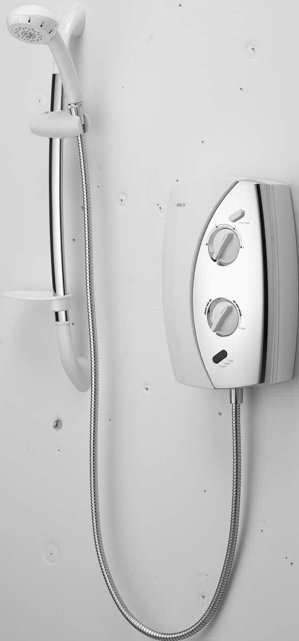
16 E50 - functions key Start/stop button Heat setting knob Flow/temperature control Power LED Overheat LED Low flow LED 16


17 E50 - user guide E50 user instructions 1 Turn on power to the shower unit. Usually a pull cord type isolator switch. The power light and low flow LED will illuminate. 2 Set the temperature/flow control knob to the full cold position. 3 Set the heat setting control knob to the desired position. The lower the setting, the cooler the temperature will be. No.1 position denotes the cold setting. 4 Press the start button. Note: the low flow LED will turn off, provided there is sufficient water flow. 5 Adjust the temperature/flow control knob slowly to select a comfortable showering temperature, allowing a few seconds after each adjustment for the temperature to stabilise. The flow rate will adjust automatically. 6 If the desired temperature cannot be reached, turn the temperature/flow control knob back to full cold position and adjust the heat setting control knob. Repeat step 5. The higher the setting the warmer the temperature will be. 7 Once showering is completed, press the stop button. Residual water will continue to drip from the shower head for a few seconds. 8 Turn off the power to the shower unit. 17


18 E50 - shower head operation Shower head operation NEVER ATTEMPT TO MAKE ANY ADJUSTMENT TO THE SHOWER HEAD BY PULLING ON THE SHOWER HOSE. 1 To select the desired spray pattern, rotate the shower spray cassette clockwise or anti-clockwise. 2 To select the preferred height for the shower head, depress the handset holder button to enable the slider to be moved up or down the rail. 3 Angular adjustment is made, by carefully but firmly pulling forwards or pushing back the shower head against the knuckle ratchet in the holder. 18
19 User guide Please refer to the user guide on page 17. After installation Inspection & maintenance In the interest of safety, we recommend this product and its electrical installation are checked by a qualified electrician at least every 2 years. After installation Familiarise the end user with the product operation and hand them this guide. Complete and post the guarantee card and optional guarantee extension agreement document. Cleaning and maintenance Your product should be cleaned using only a soft cloth and washing up liquid. DO NOT USE ABRASIVE CLEANERS. To reduce the requirement for chemical descaling in hard water areas, the shower head incorporates rub clean teats. Any scale build up that may occur in any of the holes can be broken down by gently rubbing the flexible tips of the jets during use. This procedure should be completed regularly, as often as once a week in some hard water areas as scale build up can affect the spray pattern and cause the shower to perform poorly. Failure to descale the shower head can affect the internal seals and may affect the warranty. Should chemical descaling of the head become necessary, remove the shower head and fully immerse in a mild proprietary descalent. IT IS IMPERATIVE THAT DESCALING IS CARRIED OUT STRICTLY IN ACCORDANCE WITH THE MANUFACTURERS INSTRUCTIONS. SUBSTANCES THAT ARE NOT SUITABLE FOR PLASTICS AND ELECTROPLATED SURFACES MUST NOT BE USED. 19
20 Trouble shooting guide These checks must only be performed by a competent person. Warning There are no user serviceable components beneath the cover of the appliance. IF YOU ARE UNABLE TO REMEDY THE PROBLEM WITHOUT REMOVING THE COVER, YOU SHOULD CONTACT YOUR INSTALLER OR A QUALIFIED ELECTRICIAN. Only a competent tradesperson should remove the front cover. The electrical supply to the shower MUST BE isolated at the consumer unit (fuse board) prior to the front cover being removed Where the fault cannot be corrected by yourself or your installer, DO NOT REMOVE THE UNIT FROM THE WALL, but contact the Customer Services Department, who will provide assistance over the telephone. If necessary, they can arrange a visit by a service engineer. We find the vast majority of problems can be resolved by reference to these fitting instructions or by discussion over the telephone. In the event an engineer is called and the fault is caused by faulty installation, usage or lack of reasonable maintenance, a call out charge will be made. Pressures To ensure optimal performance and that the shower is working to specification:- Try reducing the flow rate (increasing demand temperature) to increase dynamic pressure and selecting the appropriate heat setting to give required showering temperature. Check inlet requirements (see Important Information - Pressures section). Ensure no other main water devices are being used whilst showering (e.g. toilet, garden hose, washing machine, etc). Check pipework for potential blockages/pressure losses. Ensure the stop cock and servicing valves are fully open. Ensure full bore isolation valve has been fitted. Check with the local water authority to check the running pressure is above the minimum required (see Important Information Pressures section). This may be apparent during periods of high demand or when other outlets are used. IF YOU ARE UNABLE TO REMEDY THE PROBLEM WITHOUT REMOVING THE COVER, YOU SHOULD CONTACT YOUR INSTALLER OR A QUALIFIED ELECTRICIAN. ACTIONS HIGHLIGHTED IN BOLD TEXT MUST BE COMPLETED BY A QUALIFIED INSTALLER/ELECTRICIAN/SERVICE ENGINEER AS STATED. 20
21 Action Check isolator switched on, and remains on (pull cord or wall mounted switch) Check MCB or fuse at consumer unit Check RCD (if fitted) Renew the fuse or reset MCB/RCD if required If fault persists contact your installer Trouble shooting guide Possible cause Symptom - No power (power light indicator on unit not lit) Will not switch on power light not lit - Electrical supply isolated at double pole switch - Fuse blown or MCB/RCD tripped, indicating possible electrical fault - Power cut - Incorrectly wired product Low pressure/water supply turned off (low pressure indicator on unit lit when unit is operated) Will not switch on power light lit Permanent thermal trip activated Check 230/240V at shower terminal block (Installer/ electrician only task) Possible wiring fault or poor connections Faulty on/off button/switch See trouble shooting pressures section Shower has overheated. This is a non-user serviceable part, shower component must be replaced Contact Customer Services Department This is a non-user serviceable part, shower component must be replaced Contact Customer Services Department 21
22 Action See trouble shooting pressures section Fit correct hose/handset Replace damaged/kinked hose Trouble shooting guide Possible cause Symptom Low pressure/water supply turned off (low pressure indicator on unit lit when unit is operated) No flow or Not enough flow (See also poor spray pattern below) Incorrect hose/handset fitted Damaged/kinked hose Water temperature control knob is turned fully clockwise (full hot) SHOWER UNIT IS SUSPECTED OF BEING FROZEN There may be an outlet blockage Turn temperature control knob anti-clockwise (towards cold) If so, DO NOT USE a) Switch off immediately at the electrical isolation switch b) Turn off at isolation valve c) Contact our Customer Service Department Disconnect handset from hose and run the shower a) If water flows then handset is blocked with scale or debris. Clean the handset and spray plate thoroughly b) If the water does not flow, remove the hose from the shower unit i) If the water flows the hose is blocked. This could be due to damage, severe kinking or even an obstruction. The hose must be replaced with an approved hose. Contact our Customer Service Department ii) If the water does not flow, there is a blockage in the plumbing to the shower, or the shower itself or the filter iii) Contact the Customer Service Department if you suspect the shower to be at fault 22
23 Action Check flow rate/pressure see trouble shooting pressures section NB It is unlikely to achieve the requirements with a header tank Trouble shooting guide Possible cause Symptom Inlet flow rate insufficient No flow or Not enough flow (See also poor spray pattern below) Flow valve faulty Heater tank excessively scaled Incorrect heater setting Flow adequate but water too cold, or not hot enough Replace contact Customer Services Department Water flow too high Replace. In hard water areas consider the use of a water softener contact Customer Services Department Increase heater setting Reduce the flow by slowly turning the temperature control knob in a clockwise direction (towards hot). 23
24 Action See trouble shooting pressures section See trouble shooting pressures section Trouble shooting guide Possible cause Symptom Insufficient water supply Flow adequate but water too cold, or not hot enough Pressure switches not activating/ Low water pressure (low pressure indicator on unit should be lit Permanent thermal trip has operated Sensitive adjustment Possible failure of microswitch or heater element Low inlet temperature (seasonal conditions) Shower has overheated. This is a non-user serviceable part, shower unit must be replaced. Contact Customer Services Department Slowly adjust dial waiting for temperature to settle in between changes. Use a suitable continuity device to check the continuity of the microswitch or heater tank and replace parts as necessary (Installer/electrician only task). Contact Customer Services Department. Increase heat setting & temperature knob as required. Note: At times of extreme cold water inlet temperatures you may only be able to achieve a warm shower. 24
25 Action Replace. In hard water areas consider the use of a water softener. Contact Customer Services Department Trouble shooting guide Possible cause Symptom Heater tank excessively scaled Flow adequate but water too cold, or not hot enough Low voltage Faulty flow valve Water flow too low Consult a qualified electrician Water too hot Contact Customer Services Department Increase the flow by slowly turning the temperature control knob in an anti-clockwise direction (towards cold) 25
26 Action Fit correct hose/handset Replace damaged/kinked hose. Trouble shooting guide Possible cause Symptom Incorrect hose/handset fitted Flow adequate but water too hot Damaged/kinked hose Incorrect heater setting Spray plate blocked with scale or debris Water pressure too low (low pressure indicator on unit should be lit) Incorrect hose/handset fitted Temperature varies dramatically while showering Reduce heater setting Water pressure too low or unstable Clean handset spray plate - see cleaning and maintenance section See trouble shooting pressures section Fit correct hose/handset See trouble shooting pressures section 26
27 Action Clean handset spray plate - see cleaning and maintenance section Trouble shooting guide Possible cause Symptom Spray plate blocked with scale or debris Temperature varies dramatically while showering Temperature setting too high/thermal cut out operating (normally making a click sound as it does so) Partially blocked handset Damaged/kinked hose Poor spray pattern. (refer also to handset instructions) Low water inlet temperature Increase the flow by turning the temperature control knob in an anti-clockwise direction (towards cold) and/or reduce the heater selection to reduce the outlet temperature Low voltage Clean handset - see cleaning & maintenance section Replace damaged/kinked hose Flow rate will naturally be lower when the inlet temperature is low, this applies to all electric showers. Consult a qualified electrician 27
28 Trouble shooting guide Possible cause Symptom Pressure Relief Device (PRD) has operated due to excess pressure build-up in the head or hose. This has activated because of the shower outlet being reduced or blocked Water runs from bottom of unit when shower is in use Hose incorrectly fitted, or hose washer incorrectly fitted/missing Water runs from around the hose when shower is in use Inlet connection leaking Leaking Internal seals/unit leaking Shower head draining Drip from shower head Action Flow valve faulty Partially blocked/scaled handset Ensure the correct supplied handset is used and clean from limescale. Ensure the hose is not damaged or kinked. Once the restriction has been identified and cleared the PRD will self re-set Ensure hose is correctly fitted and tight Ensure hose washer is fitted correctly Ensure pipe is correctly fitted Consult Customer Services Department Tighten hose connections Remove hose & handset, empty the hose & handset of water, then reattach, and see if drips from handset continue. If so unit needs replacing, please contact Customer Services Department Clean the handset see cleaning and maintenance section 28
29 Action Trouble shooting guide Possible cause Symptom Incorrect hose/handset fitted Operation of temperature control has little or no effect on water temperature Spray plate blocked with scale or debris Flow valve faulty Heater tank failure/ Heater tank excessively scaled Microswitch failure Cover/knob fitted incorrectly, knob not correctly engaged Fit correct hose/handset Clean handset spray plate - see cleaning and maintenance section Replace contact Customer Services Department Replace. In hard water areas consider the use of a water softener. Contact Customer Services Department Replace contact Customer Services Department Switch off at consumer unit or mains fuse board. Remove front cover ensuring the service tunnel is correcty fitted flush with the unit back plate. Refit as per pages 7 and 14, taking care to position knob correctly and ensure cover is correctly fitted 29
30 Action Trouble shooting guide Possible cause Symptom Insufficient inlet pressure No change in temperature between low/medium/high setting See trouble shooting pressures section Possible failure of flow valve, heater tank or microswitch Use a suitable device to check the continuity of the microswitch or heater tank & replace parts as necessary contact Customer Services Department 30
31 Approvals The Gainsborough E50 shower is manufactured in an ISO 9001:2000 registered factory and has been designed and tested to the very highest standards. It complies with all relevant international standards for safety and reliability. 31

32 Gainsborough Bathroom Products Limited The Flyer s Way Westerham Kent TN16 1DE Customer helpline: Website: enquiries@gainsboroughshowers.co.uk Part No: B Mar 15 Please note that calls may be recorded for training and quality purposes The company reserves the right to alter, change or modify the product specifications without prior warning Registered Trademark Aqualisa Products Limited
Vitalise S,SL & SLX. User instructions
 Vitalise S,SL & SLX User instructions Contents Important information Page 3 Shower unit user instruction - Vitalise S Page 5 - Vitalise SL Page 7 - Vitalise SLX Page 9 Thermal trip Page 11 Electronic cut
Energy. Installation guide
 Energy Installation guide Contents Important information 4 - Safety information 4 - Connections 4 - Isolating valves 4 - Siting 4 - Pressures 4 - Pressure relief device 5 Product overview 5 Components
Thermostatic bar mixer valve with adjustable head Installation guide
 Bar valve Thermostatic bar mixer valve with adjustable head Installation guide Index Introduction p.3 - Safety information p.3 - Product specification p.3 Connection to supplies p.3 - Flushing p.4 - Filters
INSTANTANEOUS ELECTRIC SHOWER
 GUARANTEE / SERVICE POLICY INSTANTANEOUS ELECTRIC SHOWER GUARANTEE Designa guarantee this DS3000 product for a period of two years, from date of purchase, against mechanical and electrical defects arising
MIDAS. Installation instructions 110/220
 MIDAS Installation instructions 110/220 INDEX INTRODUCTION Page 3 Safety information Page 3 Product specification Page 3 Important information CONNECTION TO SUPPLIES Page 4 Flushing Page 4 Filters Page
Quartz. Thermo. Concealed shower valve with adjustable head. Quartz Thermo installation guide page 1
 Quartz Thermo Concealed shower valve with adjustable head Quartz Thermo installation guide page 1 Shower systems Components Quartz Thermo built-in shower valve with adjustable head QZ3111 Quartz Thermo
Ambassador. Installation guide & user instructions. Please ensure that this document is handed to the user after installation is completed
 Ambassador Installation guide & user instructions Please ensure that this document is handed to the user after installation is completed 2 Contents Introduction p.4 - Safety information p.4 - Product specification
Quartz. Digital. Concealed with adjustable height and fixed head. Quartz Digital concelaed adjustable/fixed installation instuctions page 1
 Quartz Digital Concealed with adjustable height and fixed head The Waste Electrical and Electronic Equipment (Producer Responsibility) Regulation 2004 This product is outside the scope of the European
Aquatique. Shower heads. Fixed and adjustable height heads. Aquatique shower kits installation guide page 1
 Aquatique Shower heads Fixed and adjustable height heads Aquatique shower kits installation guide page 1 Components Aquatique adjustable height shower kit concealed Chrome 560.01 / Gold 560.04 Aquatique
Thermostatic exposed shower valve and bath/shower mixer systems Installation guide
 Midas Thermostatic exposed shower valve and bath/shower mixer systems Installation guide 2 Index Introduction p.4 - Safety information p.4 - Product specification p.4 Connection to supplies p.4 - Flushing
Aqua & Instantaneous Electric Shower Installation Instructions SERVICE POLICY
 SERVICE POLICY In the event of you needing to contact the Galaxy Customer Service Department, the following procedure should be followed:- 3 5 Before telephoning the Galaxy Customer Service Department
AQUA PREMIER ELECTRONIC ELECTRIC SHOWER. Installation and User Guide
 AQUA PREMIER ELECTRONIC ELECTRIC SHOWER Installation and User Guide IMPORTANT: This booklet should be left with the user after installation and demonstration CONTENTS Section Page Section Page Introduction.......................
Bar valve with fixed and adjustable shower heads. Installation guide. Midas Plus installation instructions Page 1
 Midas Plus Bar valve with fixed and adjustable shower heads Installation guide Midas Plus installation instructions Page 1 Midas Plus Midas Plus installation instructions Page 2 Components Literature not
Quartz. Digital. Bath with bath waste filler. Quartz Digital Bath with bath waste filler installation instuctions page 1
 Quartz Digital Bath with bath waste filler The Waste Electrical and Electronic Equipment (Producer Responsibility) Regulation 2004 This product is outside the scope of the European Waste Electrical and
For use with approved Bathstore head kits. Installation guide. Viso Digital installation instructions Page 1
 Viso Digital TM For use with approved Bathstore head kits Installation guide Viso Digital installation instructions Page 1 Viso Digital Viso Digital Viso Digital installation instructions Page 2 Components
Aquamixa. Thermo. Thermostatic shower valve with manual bath fill
 Aquamixa Thermo Thermostatic shower valve with manual bath fill Aquamixa Thermo thermostatic shower valve with manual bath fill installation instuctions page 1 Shower systems Aquamixa Thermo (300.01) with
ELECTRIC SHOWER INSTALLATION and USER INSTRUCTIONS
 1 ELECTRIC SHOWER INSTALLATION and USER INSTRUCTIONS ref. 36 00 5804 issue 2 July 01 Model number Cameo 7.2kW - 95 02 1645 PLEASE READ AND UNDERSTAND THESE INSTRUCTIONS BEFORE COMMENCING INSTALLATION PLEASE
AQ150:Midas 10/9/15 14:50 Page 1 AQ150. Thermostatic bar mixer valve with adjustable head. Installation guide
 AQ150:Midas 10/9/15 14:50 Page 1 AQ150 Thermostatic bar mixer valve with adjustable head Installation guide AQ150:Midas 10/9/15 14:50 Page 2 Important information Introduction The product is an exposed
Installation and User Instructions
 36005904_Dove_2005_Fitin 5/7/05 3:04 pm Page 1 DOVE 2005 Installation and User Instructions Please read and understand these instructions before starting work Heatrae Sadia Heating, Hurricane Way, Norwich,
Rise. Digital. Bath with overflow filler. Rise Digital Bath installation instuctions page 1
 Rise Digital Bath with overflow filler The Waste Electrical and Electronic Equipment (Producer Responsibility) Regulation 2004 This product is outside the scope of the European Waste Electrical and Electronic
Multipoint. Installation and User Instructions Instantaneous Hand Wash Models: EV 2008
 Installation and User Instructions Instantaneous Hand Wash Models: EV 2008 Multipoint Please read and understand these instructions before starting work. Please leave this leaflet with the user following
THESE INSTRUCTIONS ARE TO BE LEFT WITH THE USER
 9.0 & 9.8 kw ELECTRIC THERMOSTATIC SHOWERS Installation & User Guide THESE INSTRUCTIONS ARE TO BE LEFT WITH THE USER 1 Contents Section Page Introduction... 3 Important Safety Information... 4 Pack Contents
Dream DCV. Thermostatic Dual control mixer valve range. Installation guide
 Dream TM DCV Thermostatic Dual control mixer valve range Installation guide Index Introduction p.3 - Safety information p.3 - Product specification p.3 Connection to supplies p.4 - Pipe sizing p.4 - Flushing
These instructions are to be left with the user
 MIRA ZEST ELECTRIC SHOWER Installation and User Guide These instructions are to be left with the user 1 CONTENTS Introduction... 3 Important Safety Information... 4 Pack Contents... 6 Specifications...
850DL & 950DL CREDA 850DL & 950DL ELECTRIC SHOWER. Installation and User Guide
 850DL & 950DL CREDA 850DL & 950DL ELECTRIC SHOWER Installation and User Guide IMPORTANT: This booklet should be left with the user after installation and demonstration CONTENTS Section Introduction...........................................................
T30i electric handwash Installation and operating instructions
 electric handwash Installation and operating instructions Installers please note these instructions are to be left with the user 2180153N January 2006 CONTENTS Page Important safety information 1 Introduction
Mira Sport Max with Airboost
 Mira Sport Max with Airboost 9.0 & 10.8 kw These instructions must be left with the user Installation Guide 1 INTRODUCTION our instructions and recommendations. inside the shower. The Mira Sport Max with
Electric Showers Installation Instructions & User Guide
 Electric Showers Installation Instructions & User Guide Touch Control Electric Shower 2 Year Guarantee Please keep this booklet for future reference. Installer, when you have read these instructions please
POWER SHOWERS Models 4500M 5002M 4500T 5002T
 II POWER SHOWERS Models 4500M 5002M 4500T 5002T Performance Shower Products CUSTOMER SERVICE HELPLINE: 01883 730339 CONTENTS PLEASE READ THESE INSTRUCTIONS CAREFULLY: This booklet covers all models in
Aqua Sprint AQS8 Electric Shower
 Aqua Sprint AQS8 Electric Shower Installation and Operating Instructions IMPORTANT SAFEGUARDS WHEN USING ANY ELECTRICAL APPLIANCE, BASIC SAFETY PRECAUTIONS SHOULD ALWAYS BE FOLLOWED. PLEASE READ ALL INSTRUCTIONS
Mira Elite QT 9.8kW / 10.8kW
 Mira Elite QT 9.8kW / 10.8kW These instructions must be left with the user Installation & User Guide 1 1265606-W2-D Important Safety Information WARNING! This shower can deliver scalding temperatures.
CREDA FLORIDA PLUS ELECTRIC SHOWER. Installation and User Guide
 CREDA FLORIDA PLUS ELECTRIC SHOWER Installation and User Guide IMPORTANT: This booklet should be left with the user after installation and demonstration THIS APPLIANCE CAN BE USED BY CHILDREN AGED FROM
Mira Sport Max with Airboost
 Mira Sport Max with Airboost 9.0 & 10.8 kw These instructions must be left with the user Installation Guide 1 INTRODUCTION Thank you for purchasing a quality Mira Sport Max with Airboost Electric Shower.
Installation and Operating Instructions
 . T60si electric shower. Installation and Operating Instructions INSTALLERS PLEASE NOTE THESE INSTRUCTIONS ARE TO BE LEFT WITH THE USER 2180269D Aug 2001 CONTENTS Page Important safety information 1 Introduction
PURE 7.5/8.5/9.5/10.5kW
 PURE 7.5/8.5/9.5/10.5kW Installation and User Guide IMPORTANT: This booklet should be left with the user after installation and demonstration Contents 1 Pack Contents 3 2 Installation Check List 3 3 Important
Electric Showers. Installation Instructions & User Guide. AQUA PROFILE PLUS AQP8 & AQP9 Electric Shower. 2 Year Guarantee
 Electric Showers Installation Instructions & User Guide AQUA PROFIE PUS AQP8 & AQP9 Electric Shower 2 Year Guarantee Please keep this booklet for future reference. Installer, when you have read these instructions
kW kW kW kW
 TEMPESTA 100 ELECTRIC SHOWER DESIGN + ENGINEERING GROHE GERMANY 99.0351.031/ÄM 231959/08.14 www.grohe.com 26 178 8.5kW 26 179 9.5kW 26 221 9.5kW 26 222 9.5kW IMPORTANT: This booklet should be left with
Installation Instructions and User Guide
 Installation Instructions and User Guide Thermostatic Power Shower 1000 Please keep this booklet for future reference. Installer, when you have read these instructions please ensure you leave them with
T90xr pumped. electric shower. Installation and operating instructions ! IMPORTANT!
 T90xr pumped electric shower! IMPORTANT! Under *NO circumstances must this shower be connected directly to a mains water supply. It is designed for GRAVITY FED COLD WATER systems ONLY! *Failure to comply
THESE INSTRUCTIONS ARE TO BE LEFT WITH THE USER
 8.5 and 9.5 kw Power Low Flow Temperature Stop Start ELECTRIC SHOWERS Installation & User Guide THESE INSTRUCTIONS ARE TO BE LEFT WITH THE USER 1 CONTENTS Introduction... 3 Important Safety Information...
Installation and Operating Instructions INSTALLERS PLEASE NOTE THESE INSTRUCTIONS ARE TO BE LEFT WITH THE USER E Jan 02
 . Coral/Amber electric shower. Installation and Operating Instructions INSTALLERS PLEASE NOTE THESE INSTRUCTIONS ARE TO BE LEFT WITH THE USER 2180212E Jan 02 CONTENTS Page Important safety information
Installation and Operating Instructions INSTALLERS PLEASE NOTE THESE INSTRUCTIONS ARE TO BE LEFT WITH THE USER H May 01
 . T50i electric shower. Installation and Operating Instructions INSTALLERS PLEASE NOTE THESE INSTRUCTIONS ARE TO BE LEFT WITH THE USER 2180154H May 01 CONTENTS Page Important safety information 1 Introduction
These instructions are to be left with the user
 MIRA VISTA ELECTRIC SHOWER Installation and User Guide These instructions are to be left with the user 1 CONTENTS Introduction...3 Important Safety Information...4 Pack Contents...6 Specifications...7
Mira Sport Thermostatic
 Mira Sport Thermostatic 9.0 & 9.8 kw POWER 5 6 4 7 3 8 2 9 1 TEMPERATURE 10 THERMOSTATIC These instructions must be left with the user User Guide 1 INTRODUCTION Thank you for purchasing a quality Mira
Installation and Operating Instructions
 . Amber II electric shower. Installation and Operating Instructions INSTALLERS PLEASE NOTE THESE INSTRUCTIONS ARE TO BE LEFT WITH THE USER 2180346D July 2003 CONTENTS Page Important safety information
Congratulations! You've just purchased a new Santon tankless water heater and will soon begin to enjoy the benefits of going tankless.
 by Congratulations! You've just purchased a new Santon tankless water heater and will soon begin to enjoy the benefits of going tankless. Please take the time to thoroughly read and understand this safety
T300si. wireless remote electric shower. Installation and operating instructions
 T300si wireless remote electric shower Installation and operating instructions Installers please note these instructions are to be left with the user 2180520E August 2007 Contents Page Important safety
Installation and User Instructions Instantaneous Hand Wash Models: EV 2008 No-Touch. EV 2008 No Touch
 Installation and User Instructions Instantaneous Hand Wash Models: EV 2008 No-Touch MULTIPOINT EV 2008 No Touch Please read and understand these instructions before starting work. Please leave this leaflet
Fitting Instructions and User Guide
 HANDY NO-TOUCH ELECTRIC HANDWASH Fitting Instructions and User Guide 1 INTRODUCTION Thank you for purchasing a Heatrae Sadia Handy. The Handy instantaneous water heater is manufactured to the highest standards
Mira Meta 8.5, 9.5 and 10.8 kw Electric Shower
 Mira Meta 8.5, 9.5 and 10.8 kw Electric Shower Power Temperature - + These instructions must be left with the user Installation & User Guide 1 1327878-W2-A 1327878-W2-A 2 Introduction Thank you for choosing
Kito electric shower Installation and operating instructions
 Kito electric shower Installation and operating instructions Installers please note these instructions are to be left with the user 2180658F November 2009 CONTENTS Page Important safety information...
Enrich electric shower Installation and operating instructions
 Enrich electric shower Installation and operating instructions Installers please note these instructions are to be left with the user 2180614B January 2009 CONTENTS Page Important safety information...
T80xr electric shower
 electric shower Installation and operating instructions INSTALLERS PLEASE NOTE THESE INSTRUCTIONS ARE TO BE LEFT WITH THE USER 2180455A April 2005 CONTENTS Page Important safety information 1 Introduction
Mira Jump MIRA JUMP ELECTRIC SHOWER. Installation and User Guide. These instructions are to be left with the user 1
 Mira Jump MIRA JUMP ELECTRIC SHOWER Installation and User Guide These instructions are to be left with the user 1 CONTENTS Introduction...3 Guarantee...3 Recommended Usage...3 Patents...3 Important Safety
Installation Instructions and User Guide
 Installation Instructions and User Guide Bliss Electric Showers Please keep this booklet for future reference. Installer, when you have read these instructions please ensure you leave them with the user.
Manual and Thermostatic Power Shower Units
 520M/520TS Manual and Thermostatic Power Shower Units Installation instructions & User guide IMPORTANT: This booklet should be given to the customer after installation and demonstration. WARNING: Under
T80 GSI electric shower Installation and operating instructions
 T80 GSI electric shower Installation and operating instructions INSTALLERS PLEASE NOTE THESE INSTRUCTIONS ARE TO BE LEFT WITH THE USER 2181057E January 2011 SHOWER CONTROLS - quick user guide To START
AIRE. Thermostatic bath shower mixer. Installation and Operating Instructions INSTALLERS PLEASE NOTE THESE INSTRUCTIONS ARE TO BE LEFT WITH THE USER
 AIRE Thermostatic bath shower mixer Installation and Operating Instructions INSTALLERS PLEASE NOTE THESE INSTRUCTIONS ARE TO BE LEFT WITH THE USER 2180427C October 2005 CONTENTS Page Introduction 1 Safety
TYNE. Installation and Operating Instructions. Thermostatic bath shower mixer. Installers please note these instructions are to be left with the user
 TYNE Thermostatic bath shower mixer Installation and Operating Instructions Installers please note these instructions are to be left with the user 2180426F - February 2013 CONTENTS Page Introduction...
Installation Instructions and User Guide
 Installation Instructions and User Guide Thermostatic Power Shower 1500 STOP/START SHOWER ECO Please keep this booklet for future reference. Installer, when you have read these instructions please ensure
Installation and User Instructions Instantaneous Hand Wash Models: EV 2008
 Installation and User Instructions Instantaneous Hand Wash Models: EV 2008 Please read and understand these instructions before starting work. Please leave this leaflet with the user following installation
CARINO electric shower
 electric shower Installation and operating instructions Installers please note these instructions are to be left with the user 2180842B - May 2012 CONTENTS Page Important safety information... 1 Introduction...
Mira Galena. 9.8 kw. These instructions must be left with the user. Installation and User Guide. Please call us on (UK Only)
") Mira Galena 9.8 kw For SPARES, ADVICE or REPAIRS Please call us on 0844 571 5000 (UK Only) These instructions must be left with the user Installation and User Guide 1 INTRODUCTION Thank you for purchasing
Mira Galena 9.8 kw For SPARES, ADVICE or REPAIRS Please call us on 0844 571 5000 (UK Only) These instructions must be left with the user Installation and User Guide 1 INTRODUCTION Thank you for purchasing
Mira Minilite Exposed Mira Minilite EV Mira Moto EV
 Mira Minilite Exposed Mira Minilite EV Mira Moto EV These instructions must be left with the user Installation & User Guide 1 1282641-W2-A Important Safety Information WARNING! This shower can deliver
Mira Vie Electric Shower 8.5, 9.5 & 10.8 kw
 Mira Vie Electric Shower 8.5, 9.5 & 10.8 kw For SPARES, ADVICE or REPAIRS Please call us on 0844 571 5000 (UK Only) These instructions must be left with the user Installation and User Guide 1 CONTENTS
Mira Jump MIRA JUMP ELECTRIC SHOWER. Installation and User Guide. These instructions are to be left with the user 1
 Mira Jump MIRA JUMP ELECTRIC SHOWER Installation and User Guide These instructions are to be left with the user 1 CONTENTS Introduction...3 Guarantee...3 Recommended Usage...3 Patents...3 Important Safety
Zenica black electric shower
 black electric shower Installation and operating instructions Installers please note these instructions are to be left with the user The showerhead and hose supplied with this product are a safety critical
Zenica black electric shower
 black electric shower Installation and operating instructions Installers please note these instructions are to be left with the user 2181530B - March 2018 CONTENTS Page Important safety information...
Mira Atom ERD Thermostatic Bar Valve
 Mira Atom ERD Thermostatic Bar Valve These instructions must be left with the user Installation and User Guide 1 1340912-W2-A 1340912-W2-A 2 Introduction Thank you for purchasing a quality Mira product.
Bezique II electric shower
 Bezique II electric shower Installation and operating instructions Installers please note these instructions are to be left with the user 2180591E December 2011 CONTENTS Page Important safety information...
Rapide R3 electric shower
 electric shower Installation and operating instructions Installers please note these instructions are to be left with the user 2180638E - January 2012 CONTENTS Page Important safety information... 1 Introduction...
Aviva electric shower
 Aviva electric shower Installation and operating instructions T00373 Installers please note these instructions are to be left with the user 2180676C July 2008 CONTENTS Page Important safety information...
Installation and Operating Instructions INSTALLERS PLEASE NOTE THESE INSTRUCTIONS ARE TO BE LEFT WITH THE USER A Dec 99
 . pumped electric shower. Installation and Operating Instructions INSTALLERS PLEASE NOTE THESE INSTRUCTIONS ARE TO BE LEFT WITH THE USER 2180285A Dec 99 CONTENTS Page Important safety information 1 Introduction
T80si pumped electric shower
 T80si pumped electric shower! important! Under *NO circumstances must this shower be connected directly to a mains water supply. it is designed for gravity FED COLD WATEr systems ONLY! *Failure to comply
Installation and Operating Instructions
 . TW10i handwash water heater. Installation and Operating Instructions INSTALLERS PLEASE NOTE THESE INSTRUCTIONS ARE TO BE LEFT WITH THE USER 21039A May 2002 CONTENTS Page Introduction 1 Safety warnings
Opal II electric shower Installation and operating instructions
 electric shower Installation and operating instructions Installers please note these instructions are to be left with the user 2180592B July 2008 CONTENTS Page Important safety information... 1 Introduction...
ASPIRANTE Wireless remote electric shower
 ASPIRANTE Wireless remote electric shower Installation and Operating Instructions Installers please note these instructions are to left with the user 2180523I November 2011 CONTENTS Page Important safety
Mira Jump. Installation and User Guide. These instructions are to be left with the user 1
 Mira Jump Mira Jump Electric Shower Installation and User Guide These instructions are to be left with the user 1 Contents Introduction...3 Guarantee...3 Recommended Usage...3 Patents and Design Registration...3
CROWN WATER HEATERS CPU10 - CPU15 CPOS10 - CPOS15
 CROWN WATER HEATERS CPU10 - CPU15 CPOS10 - CPOS15 COMPACT PLUS 10 and 15 Litre Unvented Under and Over Sink Water Heater INSTALLATION AND USER GUIDE 1 DIMENSIONS 10L - 250mm 15L - 310mm 100mm 80mm 410mm
Installation Instructions and User Guide
 Installation Instructions and User Guide Joy & Glee Electric Showers eco Please note: The Joy Electric Shower is shown as a typical example. Please keep this booklet for future reference. Installer, when
Aspirante remote shower
 Aspirante remote shower Installation and operating instructions Installers please note these instructions are to be left with the user 2180300L - January 2014 CONTENTS Page Important safety information...
T550i power shower pump Installation and operating instructions
 power shower pump Installation and operating instructions Installers please note these instructions are to be left with the user 2180149H March 2008 CONTENTS Page Plumbing and electrical notes...1 Introduction...2
Trance electric shower
 electric shower Installation and operating instructions T00335 Installers please note these instructions are to be left with the user 2180407I November 2011 CONTENTS Page Important safety information...
Thermostatic Control Instantaneous Electric Shower Installation and User Instructions
 Thermo Response QI Thermostatic Control Instantaneous Electric Shower Installation and User Instructions IMPORTANT! This Step-by-Step guide should be given to the customer after installation and demonstration.
9.0 & 9.8 KW MIRA SPORT THERMOSTATIC ELECTRIC SHOWER. Installation & User Guide. These instructions are to be left with the user 1
 9.0 & 9.8 KW MIRA SPORT THERMOSTATIC ELECTRIC SHOWER Installation & User Guide These instructions are to be left with the user 1 CONTENTS Patents and Design Registration...2 Introduction...3 Guarantee...3
VISAGE INSTALLATION GUIDE
 VISAGE INSTALLATION GUIDE Images for illustration purposes only, product may differ. CONCEALED COMPONENTS 1. 1. 2. 2. 1. Gravity stored water systems only 2. Mains fed and separately pumped water systems
STREAMLINE OVERSINK. Fitting Instructions and User Guide _iss_05.indd 1 15/09/ :46:30
 STREAMLINE OVERSINK Fitting Instructions and User Guide 1 36005997_iss_05.indd 1 15/09/2015 08:46:30 CONTENTS SECTION PAGE 1.0 INTRODUCTION 3 2.0 TECHNICAL SPECIFICATIONS 4 3.0 INSTALLATION 6 4.0 COMMISSIONING
Prism Thermostatic Recessed Shower with Integral 2 Outlet Diverter
 Prism Thermostatic Recessed Shower with Integral 2 Outlet Diverter Installation Instructions & User Guide Please keep these instructions for future reference and request of replacement parts Thank you
HEATRAE SADIA. Installation and User Instructions for the UTC Undersink Vented Water Heater
 HEATRAE SADIA The quality name in water heating Installation and User Instructions for the UTC Undersink Vented Water Heater UTC 15 Please read and understand these instructions before starting work. Please
T30i electric handwash
 electric handwash Installation and operating instructions Installers please note these instructions are to be left with the user 2180153T - June 2014 CONTENTS Page Important safety information... 1 Introduction...
PERFORMANCE SHOWER PRODUCTS
 INSTALLER PLEASE LEAVE INSTRUCTIONS WITH CUSTOMER PERFORMANCE SHOWER PRODUCTS INSTALLATION INSTRUCTIONS FOR REGENERATIVE MAINS SHOWER PUMP Model: PR35D Medium pressure twin PR50D Medium pressure twin PR50S
Bewitch. electric shower. Installation and operating instructions INSTALLERS PLEASE NOTE THESE INSTRUCTIONS ARE TO BE LEFT WITH THE USER
 electric shower Installation and operating instructions INSTALLERS PLEASE NOTE THESE INSTRUCTIONS ARE TO BE LEFT WITH THE USER 2180423I November 2011 CONTENTS Page Important safety information... 1 Introduction...
REDRING POWERSTREAM UNVENTED INSTANTANEOUS WATER HEATER. Installation and User Guide
 : GUARANTEE AND CONTACT DETAILS REDRING POWERSTREAM UNVENTED INSTANTANEOUS WATER HEATER Installation and User Guide APPLIED ENERGY PRODUCTS LIMITED MORLEY WAY, PETERBOROUGH PE2 JJ TEL: +44 (0) 844 372
ALICANTE electric shower
 ALICANTE electric shower Installation and operating instructions Installers please note these instructions are to be left with the user 2180378I November 2011 CONTENTS Page Important safety information...
HW3 Handwash Installation and Operating Instructions
 HW3[16]instructions 10/12/15 14:05 Page 1 HW3 Handwash Installation and Operating Instructions IMPORTANT SAFEGUARDS SPECIFICATION: HW3 RATING: 230-240V, 3000W, ~50Hz; DIMENSIONS: 170w x 190h x 80d mm;
Mira Azora Thermostatic Electric Shower Installation & User Guide. These instructions are to be left with the user
 Mira Azora Thermostatic Electric Shower Installation & User Guide These instructions are to be left with the user Contents Introduction...3 Patents and Design Registration...3 Important Safety Information...4
X62 Tap Range. Please keep these instructions for future reference
 X62 Tap Range This instruction booklet covers: X625205CP, X625215CP, X625255CP, X625265CP, X625122CP, X625126CP, X625135CP Please keep these instructions for future reference 02 For latest prices and delivery
Mira Advance THERMOSTATIC ELECTRIC SHOWER. 8.7 and 9.8 kw. These instructions must be left with the user. User Guide W5-A
 Mira Advance THERMOSTATIC ELECTRIC SHOWER 8.7 and 9.8 kw These instructions must be left with the user User Guide 1 1306246-W5-A Introduction Thank you for purchasing a quality Mira product. To enjoy the
Ivory III electric shower
 electric shower Installation and operating instructions Installers please note these instructions are to be left with the user 2180545G December 2011 CONTENTS Page Important safety information... 1 Introduction...
Installation and Operating Instructions INSTALLERS PLEASE NOTE THESE INSTRUCTIONS ARE TO BE LEFT WITH THE USER H June 99
 . Topaz T80i electric shower. 9 8 Installation and Operating Instructions INSTALLERS PLEASE NOTE THESE INSTRUCTIONS ARE TO BE LEFT WITH THE USER 2180162H June 99 CONTENTS Page Important safety information