INSTALLATION, OPERATING AND SERVICING INSTRUCTIONS BG 2000-S (V13) RU PL DE IT ES NL EN 1 662Y0600 A
|
|
|
- Shannon Elliott
- 5 years ago
- Views:
Transcription


1 INSTALLATION, OPERATING AND SERVICING INSTRUCTIONS G 2000-S (V13) 1
2 Index WARNINGS GAS FLOW RATE DIMSIONS SETTINGS PARAMETERS SERVICING THE URNER OPERATING DESCRIPTION - URNERS 4 G 2000-S 25 / 35 / 45 / 55 / 60 / 70 5 G 2000-S FITTING THE URNER 5 7 FAN SETTING PROCEDURE URNER WIRINGS G 2000-S 25 / 35 / 45 / 55 / 60 / G 2000-S ELECTRODES ADJUSTEMT URNER COMPONTS FAULT-FINDING PROCEDURES Fault table 14 Table of corrective 15 PROPANE CONVERSION 14 Assembling and dismantling the kit 16 Parameters of adjustment if you convert the burner
3 Warnings WHO SHOULD READ THESE INSTRUCTIONS These instructions should be read by: - the design engineer/consultant - the user - the installer - the service engineer CERTIFICATION The products have received CE certification in accordance with the standards in force in various countries (European Directives 92/42/EEC "efficiency requirements", 2009/142/EC "gas appliances"). SYMOLS The following symbols are used in this manual: Essential instruction for the correct operation of the installation IMPORTANT NOTES RECOMMDATIONS Essential instruction for the safety of persons and the environment Electrocution hazard: use a qualified technician Carefully read this manual before installing and bringing the boiler into service. It is prohibited to modify the interior of the appliance in any way, without the manufacturer s prior written agreement. The product must be installed by a qualified engineer, in accordance with the applicable local standards and codes. Failure to follow the instructions describing test operations and procedures could result in personal injury or a risk of environmental pollution. In order to ensure the appliance operates safely and correctly, it is important to have it serviced by an approved contractor. If there is a problem please contact your contractor for advice. In spite of the strict quality standards that ACV applies to its appliances during production, inspection and transport, faults may occur. Please notify your approved contractor immediately of any faults. Defective parts can only be replaced with original factory parts. efore carrying out any work on the boiler, it is important to isolate the electrical supply to the unit. The user must not attempt to gain access to the components inside the boiler or the control panel. This appliance is not intended for use by persons with reduced physical, sensory or mental capacities, or lack of experience and knowledge (including children), unless they have been supervised or instructed concerning use of the appliance by a person responsible for their safety. If you smell gas : - Isolate the gas supply immediately. - Ventilate the room (Open the windows). - Do not use electrical appliances and do not operate switches. - Notify your gas supplier and/or your installer immediately. These instructions are an integral part of the equipment to which they relate and must be left for the user. The product is to be installed and serviced by qualified technicians, in accordance with current regulations. The manufacturer declines all liability for any damage caused as a result of incorrect installation or in the event of the use of appliances or accessories that are not specified by the manufacturer. The manufacturer reserves the right to change the technical characteristics and features of its products without prior notice. The availability of certain models as well as their accessories may vary according to markets. 3
 is produced in the neck of the venturi.")
4 Operating The G 2000-S burner is fitted with a gas valve venturi assembly, an electronic controller, a fan, a flame holder and lighting and ionisation electrodes. CONTROLLING THE AIR GAS MIXTURE As the fan sucks in air through the venturi, a drop in pressure (P1) is produced in the neck of the venturi. The gas valve regulator then reacts to maintain a pressure differential equal to the offset value between the pressure at the gas valve outlet (P2) and atmospheric pressure (P3): P2 P3 = offset If the air flow decreases, P1 increases; the same occurs for P2; P2 is then >P3; the regulator R is moved higher to make P2 offset = P3; pressure P4 falls and the valve C is turned down: the gas flow decreases. y careful adjustment of the offset, an air gas pressure ratio of 1 is obtained, regardless of the fan speed. The pressure differential between the venturi neck and the gas valve outlet then causes gas to be sucked through the venturi. The gas flow adjustment screw can be used to adjust the quantity of gas injected for a given air flow, which will set the % CO 2 in the flue gas. A given output can then be set simply by adjusting the speed of rotation of the fan and the % CO 2 to preset values. Functional diagram C P4 P3 R 1. Air 2. Gas 3. Venturi 4. Fan 5. Offset adjustment screw 6. Gas flow a adjustement screw (CO 2 ) 7. Air - gas mixture 5 P1 3 4 P2 6 LIGHTING AND FLAME CONTROL The burner control unit performs the tasks of lighting the burner by producing a spark at the ignition electrode, and maintaining the flame when the gas valve is opened by measuring the ionisation current. The lighting sequence is shown in the diagram below: When the boiler thermostat detects a demand for heat, the fan starts; after 10 seconds of preliminary flushing, the gas valve is opened and simultaneously a spark is produced. If an ionisation current is detected in the first 5 seconds, combustion occurs normally until the end of the demand. If not, the gas valve is closed and the fan stopped, the burner being in safety mode. It must then be reset manually before lighting is attempted again. Sequence of starting G 2000-S 25 / 35 / 45 / 55 / 60 / 70 G 2000-S 100 Ionisation Spark Gas valve opens Fan Sec. Pre-ignition Thermostat Ionisation Spark Gas valve opens Fan Sec. Pre-ignition Thermostat 4

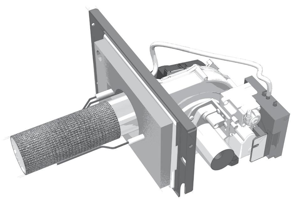
5 Description - burners G 2000-S 25 / 35 / 45 / 55 / 60 / urner 2. Ignition electrode 3. Gas valve 4. Venturi 5. urner chamber plate seal 6. urner chamber plate insulation 7. Ionisation electrode 8. Fan 9. urner chamber plate 10. Flame inspection window 11. urner plug 12. Potentiometer setting 13. Fan power plug 14. urner control 15. Gas supply G 2000-S 25 / 35 / 45 / 55 / 60 /
 5. urner chamber plate seal 6. urner chamber plate insulation 7. Ionisation electrode 8.")

6 Description - burners G 2000-S urner 2. Ignition electrode 3. Gas valve (2x) 4. Venturi (2x) 5. urner chamber plate seal 6. urner chamber plate insulation 7. Ionisation electrode 8. Fan G 2000-S Flame inspection window 10. urner chamber plate 11. urner plug 12. Potentiometer setting 13. Fan power plug 14. urner control 15. Gas supply 16. Air box


 7")


7 Fitting the burner Adjust the CO 2 (see page 8) 7
8 Gas flow rate Measure burner combustion using an electronic flue gas analyser. Adjust the % CO 2 to the value given in the setting parameter table by turning the gas flow adjustment screw (1, illustration R): anticlockwise for increased flow (rise in %CO 2), clockwise for decreased flow (tall in % CO 2). 2 Venturi & gas valve 1. Gas flow adjustement screw (CO 2 ). 2. Pressure offset measurement. 3. Upstream gas pressure measurement. 4. Offset adjusting screw cover (Never touch this screw!) 4 Warning! To respect the parameters of the offset adjustement mentioned again in the table above. Settings parameters urners G 2000-S / 25 G 2000-S / 35 G 2000-S / 45 G 2000-S / 55 oilers Delta Performance 25 Delta Pro 25 Delta Performance 35 Alfa Sprint S / SV HeatMaster 30 N Delta Performance 45 Delta Pro 45 Delta Performance 55 Delta Pro 55 Output kw Note: The offset value is set at the factory. The burner can only be fitted to one of the boilers in the table above. 1 3 G20 - G25 % CO 2 Rpm max. G31 % CO 2 Rpm max. 25,0 9, / 11, ,9 9, / 11, ,0 9, / 11, ,0 9, / 11, G 2000-S / 60 HeatMaster 60 N 69,9 9, / 11, G 2000-S / 70 HeatMaster 70 N 69,9 9, / 11, G 2000-S / kw HeatMaster 100 N 85,0 9, / 11, G 2000-S / kw HeatMaster 100 N 107,0 9, / 11,
 1.")


9 Fan setting procedure FAN ROTATION SPEED (Rpm) 1. Remove the green protective disk 2. Release the clips of the fan motor cover. 3. Remove the cover protection of the fan. 4. Adjust the speed of the fan using the settings in the table underneath rotate counter clockwise to reduce and clockwise to increase the fan speed once the fan is adjusted please remount the fan motor cover. 9
10 urner wiring G 2000-S 25 / 35 / 45 / 55 / 60 / 70 S3 T2 T1 N L Power supply plug 2. Fan supply 3. urner control supply 4. Internal connection 230 V ~ 50HZ L1 N T1 T2 S lue k. lack r. rown R. Red Y/Gr. Yellow / Green r k L1 PE N Y/Gr r R T1 T2 S3 4 k r R Y / Gr r If on the control panel the warning-light: urner lock-out continuously lights up as the burner runs, please check if on the boiler-connector the bridge between 12 and 15 (for jet-burners) is replaced by the bridge 15 and 16 (for G 2000-S) See also installation manual: "HeatMaster 30 N / 60 N / 70 N". k
11 urner wiring G 2000-S 100 S3 T2 T1 N L1 230 V ~ 50HZ 4 1. Power supply plug 2. Connector box 3. Earth connection 4. Ignition transformer 5. Ignition cable 6. Fan supply 7. Gas valve supply 3 4 r Y/Gr 5 r Y / Gr r r r r L1 Y/Gr k N L1 PE N r V T1 V T2 k S3 4 T1 T2 S S1 A PE PE PE N N N C S2 Y/Gr Y/Gr Y/Gr If on the control panel the warning-light: urner lock-out continuously lights up as the burner runs, please check if on the boiler-connector the bridge between 12 and 15 (for jet-burners) is replaced by the bridge 15 and 16 (for G 2000-S) See also installation manual: "HeatMaster 100 N". Y/Gr r Y/Gr r. lue k. lack r. rown V. Violet Y/Gr. Yellow / Green
 537D8185 urner control : Honeywell DKG 972-N-mod28 (G 2000-S / 100) 537D8189 RG 148 1200 3612 (G 2000-S / 25-35 - 45-55 - 60-70) 537D3008 Fan : MVL RG 148 1200 3633 (G 2000-S / 100)")
 537D6038 VF-051 45900446-501 (G 2000-S / 55-60 - 70-100) 537D4028 Ø 63 mm L. 287 mm (G 2000-S / 35 HM 30 N) 537DZ004 Ø 63 mm L.")
12 Electrodes adjustement 4-6 mm : G 2000-S / 35 HM 30 N 8-12 mm : G 2000-S / 25 / 45 / 55 / 60 / 70 / urner components Description Model reference Code S4965 A (G 2000-S / ) 537D8185 urner control : Honeywell DKG 972-N-mod28 (G 2000-S / 100) 537D8189 RG (G 2000-S / ) 537D3008 Fan : MVL RG (G 2000-S / 100) 537D3037 VK4115V2038U (G 2000-S / ) 537D4073 Gas valve : Honeywell VK4115V1014 (G 2000-S / 100) 537D4009 VF (G 2000-S / 25 / 35 HM 30 N ) 537D4034 Venturi : Honeywell VF (G 2000-S / 45) 537D6038 VF (G 2000-S / ) 537D4028 Ø 63 mm L. 287 mm (G 2000-S / 35 HM 30 N) 537DZ004 Ø 63 mm L. 224,5 mm (G 2000-S / ) + NIT 537DZ017 urner : Furigas Ø 63 mm L. 313,5 mm (G 2000-S / ) + NIT 537DZ029 Ø 98 mm L. 372 mm (G 2000-S / 100) + NIT 537DZ019 12
13 Dimensions URNER A C A G 2000-S / G 2000-S / 35 HM 30 N G 2000-S / G 2000-S / G 2000-S / C G 2000-S / G 2000-S / Servicing the burner 1. After removing the burner, check the condition of the ignition (A) and ionisation () electrodes, insulation (C) and burner chamber seal (D). Change them if necessary. 2. Check the condition of the flame holder (E). 3. Refit the burner and check that the burner lights. 4. Check the gas connection for leaks. 5. Ensure correct combustion. C A E G 2000-S D 13
14 Fault-finding procedures FAULT TALE Condensation in chimney : Smell of flue gas : Insufficient heating : urner switches to safety mode after lighting : Circulator : Not enough hot water : Circulator does not turn : urner does not light : Manual reset safety thermostat has actuated : Corrective measures Problems Reasons Chimney cold and/or not lined 1 oiler T set too low 2 Chimney blocked 3 ack draught in chimney 3 oiler room vents insufficient or nonexistent 4 oiler clogged 5 urner clogged 5 Room thermostat T set too low 6 Circulator blocked or faulty 7 oiler switch in Summer position or faulty 8 Not enough water in the system 9 Radiator valves closed 10 Air in the system not vented properly 9 Gas pressure insufficient 11 Gas pipe too small 11 oiler thermostat is faulty 12 Electrical system not earthed (properly) 13 The system fuses have blown 14 Air in the system and/or boiler not vented properly 9 Interval for large drawoff is too short 15 Drawoff flow rate is too high 15 Room thermostat not in demand or faulty 16 Summer/Winter switch faulty 17 On/Off switch faulty or not on C limit thermostat has activated 12 Manual reset safety thermostat has activated 19 urner fan faulty 20 Lighting electrode faulty or badly adjusted 21 Ionisation electrode faulty or badly adjusted 21 urner connectors not plugged in properly 22 Gas valve does not open 23 oiler thermostat faulty 12 Air in top of boiler not vented properly 9 14
15 TALE OF CORRECTIVE Corrective measures Fit lining in chimney 1 Set boiler T higher 2 Check and clean chimney 3 Comply with local regulations on boiler room ventilation 4 Clean burner and boiler 5 Set room thermostat to desired temperature 6 Clear or replace the circulator 7 Set switch to Winter position or replace switch 8 Fill and vent the system and boiler properly 9 Open radiator valves or adjust thermostatic valves 10 Check that pipes and meter are suitable for the system 11 Replace boiler thermostat 12 Ensure electrical system complies with the regulations 13 Change fuses and find out what caused the problem 14 Keep within the ratings stated by ACV 15 Set the thermostat to the desired temperature or replace 16 Replace Summer/Winter switch 17 Replace On/Off switch 18 This is not normal, find the cause 19 Replace fan 20 Replace electrode or adjust properly 21 Insert connectors properly 22 Replace gas valve ensuring setting parameters are correct 23 This table may be used after instruction received at ACV 15

. 4.")
. 5. Remove the venturi from the valve (3 Torx screws, fig. 3). 6.")
. 7.")

 referring to the table (page 17).")
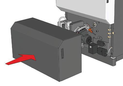
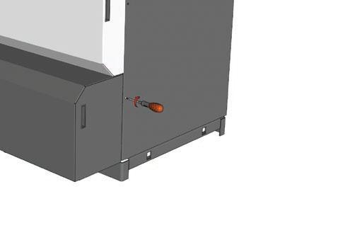
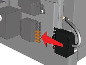
16 Propane conversion ASSEMLING AND DISMANTLING THE KIT 1. Switch off the boiler and disconnect it from the mains. 2. Remove the combustion chamber door and the burner from the boiler. 3. Remove the relay (1 screw, fig. 1). 4. Remove the valve - venturi unit from the fan (2 Torx screws, see fig. 2). 5. Remove the venturi from the valve (3 Torx screws, fig. 3). 6. Fit the right diaphragm (see table on page 3) to the centre of the joint of the valve and the venturi (fig. 4). 7. Refit the burner proceeding in reverse assembly order. 8. Power on and start up the boiler. 9. Adjust the fan speed and the % of CO 2 using the pressure regulator (fig. 5, marked A) referring to the table (page 17). Use a torx screwdriver ref. TX Adjust the % of CO 2 using a combustion device Never touch this screw!
17 PARAMETERS OF ADJUSTMT IF YOU CONVERT THE URNER Alfa Sprint S / SV 35 Delta Performance G35 HeatMaster 30 N Delta Performance G25 Delta Pro G25 Delta Performance G45 Delta Pro G45 Delta Performance G55 Delta Pro G55 HeatMaster 60 N / 70 N / 100 N G 2000-S 35 G 2000-S 25 G 2000-S 45 G 2000-S 55 G 2000-S 60 G 2000-S 70 G 2000-S kw G 2000-S kw Ø 52 Ø 52 Ø 60 Ø 68 Ø 68 urners G 2000-S / 25 G 2000-S / 35 G 2000-S / 45 G 2000-S / 55 oilers Delta Performance 25 Delta Pro 25 Delta Performance 35 Alfa Sprint S / SV HeatMaster 30 N Delta Performance 45 Delta Pro 45 Delta Performance 55 Delta Pro 45 Output kw G20 - G25 % CO 2 Rpm max. G31 % CO 2 Rpm max. 25,0 9, / 11, ,9 9, / 11, ,0 9, / 11, ,0 9, / 11, G 2000-S / 60 HeatMaster 60 N 69,9 9, / 11, G 2000-S / 70 HeatMaster 70 N 69,9 9, / 11, G 2000-S / kw HeatMaster 100 N 85,0 9, / 11, G 2000-S / kw HeatMaster 100 N 107,0 9, / 11,
18 18
19 19
20 20
BG2000S PRE-MIX GAS BURNER
 BG000S PRE-MIX GAS BURNER INSTALLATION OPERATION & MAINTENANCE DOCUMENTATION STOKVIS ENERGY SYSTEMS 96R WALTON ROAD EAST MOLESEY SURREY KT8 0DL TEL: 08707 707 77 FAX: 08707 707 767 E-MAIL:info@stokvisboilers.com
HeatMaster. Installation, operating and servicing instructions. HeatMaster 71 HeatMaster 101 HeatMaster 201 ENGLISH FRANCAIS NEDERLANDS ESPAÑOL
 HeatMaster ENGLISH Installation, operating and servicing instructions HeatMaster 71 HeatMaster 101 HeatMaster 201 664Y2500. EN 1 ENGLISH INDEX IMPORTANT NOTES 3 Who should read these instructions 3 Symbols
Installation, operating and servicing instructions
 English 57-115 - 144-1 - 259 Installation, operating and servicing instructions ITALIA EN 1 ITALIA English INDEX WARnINGS 3 Who should read these instructions 3 Symbols 3 Recommendations 3 Importants notes
INSTALLATION, OPERATION AND MAINTENANCE INSTRUCTIONS
 INSTALLATION, OPEATION AND MAINTANCE INSTUCTIONS HeatMaster 71 101 201 1 664Y6100 TALE OF CONTTS WANINS 3 Who should read these Instructions 3 Symbols 3 ecommendations 3 Warnings 3 USE UIDE 4 Use of the
INSTALLATION, OPERATION AND MAINTENANCE INSTRUCTIONS
 NSTALLATN, PERATN AND MANTANCE NSTRUCTNS HeatMaster 00 N 00 F HeatMaster 00 N / 00 F : 664Y6300 TALE F CNTTS WARNNGS 3 Who should read these nstructions 3 Symbols 3 Warnings 3 Recommendations 3 USER S
INSTALLATION AND MANINTENANCE INSTRUCTIONS
 INSTALLATION AND MANINTENANCE INSTRUCTIONS Appr. Nr. A 9503 T - 0085 AQ 0765 PEGASUS F2 T HIGH EFFICIENCY GAS-FIRED CAST-IRON BOILERS Models 51-68 - 85-102 2 Contents 1. General technical data 2. Dimensional
INSTALLATION, OPERATION AND MAINTENANCE INSTRUCTIONS
 NSTALLATN, PERATN AND MANTANCE NSTRUCTNS HeatMaster 30 N 60 N 70 N 100 N 1 664Y5400 TALE F CNTTS WARNNGS 3 Who should read these nstructions 3 Symbols 3 Recommendations 3 Warnings 3 NSTALLATN 14 Package
Installation, operating and maintenance instructions
 English Prestige50-75 - 120 MCA-5 Installation, operating and maintenance instructions EN 1 English INDEX Important notes 3 Who should read these instructions 3 Symbols 3 Recommendations 3 Certification
A/23 MFFI - A/27 MFFI
 A/23 MFFI - A/27 MFFI G.C.N. 47-6-0 / 47-6-2 Servicing Instructions Type C Boilers LEAVE THESE INSTRUCTIONS ADJACENT TO THE GAS METER TABLE OF CONTENTS Page No.. SERVICING INSTRUCTIONS. Replacement of
Open Vented Condensing Boilers
 Dimplex 18 OV Dimplex 32 OV Open Vented Condensing Boilers User s Operating Instructions These instructions should be left with the user Dimplex Boilers 2008 CONTENTS SECTION DESCRIPTION PAGE 1.0 Using
Installation, Operating and Servicing Instructions
 ENGLISH Installation, Operating and Servicing Instructions EN 1 ENGLISH INDEX WARNINGS 3 Who should read these instructions 3 Symbols 3 Recommendations 3 Applicable standards 3 Warnings 3 INTRODUCTION
Q - Series Boiler. Troubleshooting Manual
 Q - Series Boiler Troubleshooting Manual WARNING There are a number of live tests that are required when fault finding this product. Extreme care should be used at all times to avoid contact with energized
Servicing Instructions Type C Boilers G.C.N: LEAVE THESE INSTRUCTIONS ADJACENT TO THE GAS METER
 Servicing Instructions Type C Boilers G.C.N: 4-6-0 47-6-08 47-6-09 47-6-3 LEAVE THESE INSTRUCTIONS ADJACENT TO THE GAS METER TABLE OF CONTENTS Page No.. SERVICING INSTRUCTIONS. Replacement of Parts 3.2
User Manual FLOWMAX-90. for model. Condensing water heater 85,000 BTU. Installation, operating, commissioning and maintenance instructions.
 User Manual for model FLOWMAX-90 Condensing water heater 85,000 BTU WARNING If the information in these instructions is not followed exactly, a fire or explosion may result, causing property damage, personal
ATMOSPHERIC GAS BOILER INSTALLATION, OPERATING AND MAINTENANCE MANUAL
 STREBEL GENEVA CE ATMOSPHERIC GAS BOILER INSTALLATION, OPERATING AND MAINTENANCE MANUAL INDEX TABLE 1 TECHNICAL DATA SECTION 1 SECTION 2 SECTION 3 SECTION 4 SECTION 5 SECTION 6 SECTION 7 SECTION 8 SECTION
Prestige. Prestige Solo Prestige AquaSpeed Prestige Excellence Installation, Operating and Servicing Instructions
 Prestige Installation, Operating and Servicing Instructions Prestige Solo 24 32 Prestige AquaSpeed 24 32 Prestige Excellence 24 32 excellence in hot water 05/11/23 664123 INDEX INTRODUCTION 2 INSPECTION
SIME FORMAT WALL HUNG BOILERS MODEL 34i AND MODEL 34e. cod A
 cod. 6272262A GENERAL DATA Heating Data Heat Output Input (Adjustable) (Adjustable) Format 34i 11.2 34KW 45 145MJ/hr Format 34e 11.2 34KW 45 145MJ/hr General Specifications FORMAT 34i 34e Main burner injectors
Great Britain en. Installation, user and service manual. Control panel HMI Gas 310/610 ECO PRO
 Great Britain en Installation, user and service manual Control panel HMI Gas 310/610 ECO PRO Dear Customer, Thank you very much for buying this appliance. Please read through the manual carefully before
Servicing manual. Wall-mounted condensing gas boiler 600 Series - 11S / 19S / 24S / 24C /2002 GB(EN) For trade use
 For trade use") GB122 7210 1300-12/2002 GB(EN) For trade use Servicing manual Wall-mounted condensing gas boiler 600 Series - 11S / 19S / 24S / 24C Please read thoroughly before attempting to diagnose fault List of contents
GB122 7210 1300-12/2002 GB(EN) For trade use Servicing manual Wall-mounted condensing gas boiler 600 Series - 11S / 19S / 24S / 24C Please read thoroughly before attempting to diagnose fault List of contents
Servicing manual. 600 Series - 11S / 19S / 24S / 24C. Wall-mounted condensing gas boiler. For trade use
 GB122 Servicing manual Wall-mounted condensing gas boiler 600 Series - 11S / 19S / 24S / 24C For trade use Please read thoroughly before attemting to diagnose fault 7217 4900 (03/2010) GB/IE List of contents
This appliance must be installed and serviced by a competent person as stipulated by the
 DOMINATORPLUS GAS RANGE APPLIANCES (Refer to Section 1.1 for models covered by this document) INSTALLATION and SERVICING INSTRUCTIONS This appliance must be installed and serviced by a competent person
MAINTENANCE AND SERVICE GUIDE
 c Dimensions MAINTENANCE AND SERVICE GUIDE System II 80 and 100 Central Heating Fanned Flue Boiler Sizes in mm Flue types: C 12 or 42: horizontal C 32 xx: vertical concentric C 32 xy: Twin flue Boiler
SERVICE MANUAL RIVA COMPACT M90E.24S M90E.28S M90E.32S Wall hung, fan flue, room sealed gas boiler
 Wall hung, fan flue, room sealed gas boiler SERVICE MNUL RIV COMPCT Models: G.C. ppl. No. M90E.24S 47--970--17 M90E.28S 47--970--18 M90E.32S 47--970--21 Leave this manual adjacent to the gas meter iasi
INSTALLATION, OPERATION AND MAINTENANCE INSTRUCTIONS. HeatMaster TC 664Y6800 A
 INSTALLATION, OPERATION AND MAINTENANCE INSTCTIONS HeatMaster 25-35 - 45-70 - 85-120 TC 664Y6800 A TALE OF CONTENTS GENERAL RECOMMENDATIONS...4 USER'S GUI...5 Instructions for the d user... 5 Periodic
Forced draught gas burner
 Installation, use and maintenance instructions Forced draught gas burner Code Model Type 3751982 GAS 3 519T80 291 (3) - 02/2010 DECLARATION Declaration of conformity in accordance with ISO / IEC 17050-1
Service manual RIVA ADVANCE HE M110.24SM/C M110.32SM/C Wall hung, fan flue, room sealed, high efficiency gas boiler
 Wall hung, fan flue, room sealed, high efficiency gas boiler Service manual RIV DVNCE HE Models: G.C. ppl. No. M110.24SM/C 47---970---29 M110.32SM/C 47---970---30 Leave this manual adjacent to the gas
ProCon Streamline Gas Condensing Boiler. Installation and Operating Manual.
 1 MHG Heating Ltd ProCon Streamline Gas Condensing Boiler. Installation and Operating Manual. Unit 4 Epsom Downs Metro Centre, Waterfield, Tadworth, Surrey, KT20 5LR Telephone 08456 448802 Fax 08456 448803
User Manual for model
 User Manual for model RKA 24/8 RKA 24 RKA 28 RKA 34 Wall mounted storage combi boiler premix condensing boiler User instruction CE 0694 RKA 24.8_24_28_34 - RAD - ING - MAN.UT - 1104A - DIGITECH 2 - REGNO
Mikrofill Ethos Condensing combination boiler. Maintenance Instructions 24cc
 Mikrofill Ethos Condensing combination boiler Maintenance Instructions 24cc IMPORTANT Benchmark Installation, Commissioning and Service Record Log Book is enclosed in your customer information pack. This
HeatMaster 25 C. Installation, operating and maintenance. excellence in hot water 664Y4500 E
 HeatMaster 25 C English Installation, operating and maintenance instructions excellence in hot water INDEX Important notes 4 ho should read these instructions 4 Symbols 4 Recommendations 4 Certification
INSTALLATION, OPERATION AND MAINTENANCE INSTRUCTIONS,
 EN INSTALLATION, OPERATION AND MAINTENANCE INSTCTIONS, for the User and the Installer HR i 320-600 - 800 A1002237-661Y1300 B EN EN TABLE OF CONTENTS GENERAL RECOMMENDATIONS...3 PRODUCT INFORMATION...4
Light oil burners. One stage operation
 Installation, use and maintenance instructions Light oil burners One stage operation CODE MODEL TYPE 3505 RDB CF 38 50 T3 350050 RDBR CF 6 50 TR 35050 RDBR CF 33 50 TR 35050 RDBR CF 38 50 T3R 350650 RDBR
Parts Available from
 Montage und Bedienungsanleitung Manuel d entretien Installation, use and maintenance instructions Installatie-, gebruiks- en onderhoudsvoorschriften Oδηγίες εγκατάστασης, χρήσης και συντήρησης D F GB NL
User Manual for model RK 18 RK 25 RK 34 CE 0694 RK 18_25_34 - RAD - ING - MAN.UT A - DIGITECH 2 - REGNO UNITO - EXTRAHEAT - CBD
 User Manual for model RK 18 RK 25 RK 34 Premix condensing boiler User instruction CE 0694 RK 18_25_34 - RAD - ING - MAN.UT - 1104A - DIGITECH 2 - REGNO UNITO - EXTRAHEAT - CBD Technical specification by
NH DV NH DV
 RITZ America Corporation GAS-FIRED DIRECT VENT OILER NH-00- DV NH-0- DV Rev: January, 00 Service Manual Refer to this manual whenever performing service or maintenance on this appliance. This manual will
Aqua Balance. AquaBalance TM CONTROL MODULE QUICK START GUIDE LEGEND
 Aqua Balance AquaBalance TM CONTROL MODULE QUICK START GUIDE 10 1 Domestic Hot Water temperature setpoint decreasing button 2 Domestic Hot Water temperature setpoint increasing button 3 Central Heating
User Manual RBS 24. for model CE series ENERGY. Wall mounted instantaneous combi boiler room sealed chamber
 User Manual for model RBS 24 series ENERGY Wall mounted instantaneous combi boiler room sealed chamber CE 0694 RBS 24 - SERIE ENERGY - RAD - ING - MAN.UT - 1407.1 - DIGITECH TR - MIAH6 - E04 Technical
WHE 2.24 / WHE 2.24 FF
 EN Wall-hung gas boilers WHE 2.24 WHE 2.24 FF User Guide 300011777-001-C . Contents 1 Introduction.............................................................................3 1.1 Symbols used...........................................................................................3
O. Gas boiler. Gaz 6000 W WBN H-E-N/L-S2400. Operating instructions for the end customer (2017/09) en
 en") 8 716 473 216-00.3O Gas boiler WBN 6000-30-H-E-N/L-S2400 Operating instructions for the end customer en 2 Contents Contents 1 Key to symbols and safety instructions................... 2 1.1 Key to symbols..................................
8 716 473 216-00.3O Gas boiler WBN 6000-30-H-E-N/L-S2400 Operating instructions for the end customer en 2 Contents Contents 1 Key to symbols and safety instructions................... 2 1.1 Key to symbols..................................
BENSON LINEAR RADIANT TUBE
 BENSON LINEAR RADIANT TUBE Natural or Propane (Gas fired) I N S T A L L A T I O N C O M M I S S I O N I N G S E R V I C I N G U S E R I N S T R U C T I O N S September 2001 CONTENTS Page Compliance Notices
CONVERSION TO PROPANE MANUAL M-Series Condensing Boiler. Wall-Mounted, Gas-Fired Boiler
 rinnai.us 1-800-621-9419 CONVERSION TO PROPANE MANUAL M-Series Condensing Boiler Wall-Mounted, Gas-Fired Boiler For the Conversion from Natural Gas (NG) to Liquid Propane Gas (LPG) MODELS M060C M090C M120C
prestige Condensing Water Boiler SERVICE TECHNICIAN S TROUBLE SHOOTING GUIDE TSG-SOLO-9/04
 prestige Condensing Water Boiler SERVICE TECHNICIAN S TROUBLE SHOOTING GUIDE 2004-28 TSG-SOLO-9/04 Table of Contents INTRODUCTION Page 1 SERVICING TIPS AND INSTRUCTIONS Page 3 CONTROL MODULE DISPLAY -
PowerVent. Installation manual (GB) English. Store this document in a safe place UK
 English. Store this document in a safe place UK") PowerVent Installation manual (GB) Store this document in a safe place 959.034.03.UK GB Contents Blz Foreword 3 1. Introduction 3 2. CE declaration 4 3. SAFETY 4 3.1 General 4 3.2 Regulations 4 3.3 Precautions
PowerVent Installation manual (GB) Store this document in a safe place 959.034.03.UK GB Contents Blz Foreword 3 1. Introduction 3 2. CE declaration 4 3. SAFETY 4 3.1 General 4 3.2 Regulations 4 3.3 Precautions
Service Manual 3 Heater MPS & AUTO EMS Vol 1 of 2 Approved Issue 10 Printed 13/02/ :52:21 AM 1
 Service Manual 3 Heater MPS & AUTO EMS Vol 1 of 2 Approved Issue 10 Printed 13/02/2014 11:52:21 AM 1 Index Pages INTRODUCTION:......... 4-5 THE N-G1/lo INSTALLATION & SET-UP INSTRUCTIONS:......... 6-8
Conversion Instructions Logano G234X. Gas boiler. Please read carefully before installing and servicing. Gas boiler
 Gas boiler UPON COMPLETION OF THE INSTALLATION THE INSTALLER MUST INSTRUCT THE OWNER AND OPERATOR ON THE FUNCTIONALITY AND THE PROPER OPERATION OF THE BOILER AND THE HEATING SYSTEM. INSTALLER MUST REVIEW
Oil burners Brûleurs fioul Stookoliebranders
 Installation, use and maintenance instructions Manuel d entretien Installatie-, gebruiks- en onderhoudsvoorschriften GB F NL Oil burners Brûleurs fioul Stookoliebranders One stage operation Fonctionnement
Gas Instantaneous Water Heater
 6 720 607 823 GB (06.06) SM Installation and Operating Instructions Gas Instantaneous Water Heater WR10..B... WR11..B... With electronic ignition and triple safety system consisting of ionisation detector,
Service manual GARDA HE MK2. M96A.24SM/B Combi boiler M96A.28SM/B Combi boiler
 Wall hung, fan flue, room sealed, high efficiency gas boiler Service manual GRD HE MK2 Models: G.C. ppl. No. M96.24SM/ 47---583---15 Combi boiler M96.28SM/ 47---583---16 Combi boiler Leave this manual
User Manual for model
 User Manual for model RKA 24 /20 Wall mounted storage combi boiler premix condensing boiler CE 0694 Technical specification RADIANT BRUCIATORI S.p.A. Montelabbate RKA 24.20 - RAD - ING - MAN.UT - 1309.1
T UNI 7000 F. Operating instructions For the user (2006/05) AU/GB
 AU/GB") 6 720 648 662-00.1T UNI 7000 F Operating instructions For the user AU/G 2 Contents Contents Contents 2 1 Safety information and explanation of symbols 3 1.1 For your safety 3 1.2 Explanation of symbols
6 720 648 662-00.1T UNI 7000 F Operating instructions For the user AU/G 2 Contents Contents Contents 2 1 Safety information and explanation of symbols 3 1.1 For your safety 3 1.2 Explanation of symbols
Operating instructions
 The energy you need Operating instructions Betacom 3 24c -A (H-GB) 30c -A (H-GB) GB, IE Contents Contents 1 Safety... 3 1.1 Action-related warnings... 3 1.2 Intended use... 3 1.3 General safety information...
INSTALLATION AND OPERATION MANUAL
 INSTALLATION AND OPERATION MANUAL PRESSURISED STEEL BOILERS AR 30 AR 1000 RADIALAND - BOILER's INSTALLATION MANUAL version 1.0 / 15-02-2008 The company E. is outstanding in the field of central heating
Synergy Grill User & Engineer Installation & Conversion Guide
 Synergy Grill 1300 User & Engineer Installation & Conversion Guide 1 Index: Description Page Number/Section Important Information 3 Installation 4-6 / Section 1 Commissioning 6 / Section 2 Converting Gas
VIESMANN. Installation and service instructions VITODENS 111-W. for contractors
 Installation and service instructions for contractors VIESMANN Vitodens 111-W Type B1LA, 6.5 to 35.0 kw Gas condensing storage combi boiler Natural gas and LPG version Gas Council no.: 47-819-23; 47-819-24;
Indirect gas-fired air heater
 Indirect gas-fired air heater SERIES HD INSTALLATION AND SERVICE MANUAL MANUFACTURED BY : BROTHERS LIMITED WARNING Improper installation, modification, adjustment or maintenance may cause damage, injury
INSTALLATION, OPERATION AND MAINTENANCE INSTRUCTIONS, for the User and the Installer. SMART Line. Smart ME A Y2000 B
 INSTALLATION, OPERATION AND MAINTENANCE INSTCTIONS, for the User and the Installer SMART Line Smart ME 00-300 - 400-600 - 800 A00859-66Y000 B TABLE OF CONTENTS GENERAL RECOMMENDATIONS...4 PRODUCT INFORMATION...5
Installation, operation and maintenance instructions. HRi Y1300-A
 Installation, operation and maintance instructions HRi 321-601 - 800 Table of contts Geral Recommdations...4 User's Guide...5 Control Panel... 5 Appliance Description...6 Models - HRi 321 601-800... 6
CAST IRON ATMOSPHERIC BOILERS
 CST IRON TMOSPHERIC OILERS 006 gas-fired, central heating only, electronic ignition High efficiency boilers designed heating large domestic application. Ideal for installation in any boiler room. Cast-iron
Light oil - kerosene burner
 Installation, use and maintenance instructions Light oil - kerosene burner One stage operation CODE MODEL TYPE 374374 G3B 437T 90 (4) - 05/0 TECHNICAL FEATURES TYPE 437T Thermal power output 9 35 kw.6
Service manual RIVA COMPACT HE M96.24SM/C M96.28SM/C M96.32SM/C M96.24SR/C2 M96.28SR/C
 Wall hung, fan flue, room sealed, high efficiency gas boiler Service manual RIV COMPCT HE Models: G.C. ppl. No. M96.24SM/C2 47---583---05 M96.28SM/C2 47---583---06 M96.32SM/C2 47---583---07 M96.24SR/C2
GB24 & GB30. User Manual
 GB24 & GB30 User Manual BOILER OUTPUT To Domestic Hot Water:To Central Heating: GB24/30 Minimum 8.0 kw (27,296 Btu/h) GB24 Maximum 24.2 kw (82,570 Btu/h) GB30 Maximum 30.3 kw (103,384 Btu/h) GB24/30 Minimum
Operating instructions
 Operating instructions Capriz 2 24c 28c GB, IE Contents Contents 1 Safety... 3 1.1 Action-related warnings... 3 1.2 Intended use... 3 1.3 General safety information... 4 2 Notes on the documentation...
VIESMANN. Service instructions VITORONDENS 200-T. for contractors. Vitorondens 200-T Type BR2A, 20.2 to 53.7 kw Oil Unit condensing boiler
 Service instructions for contractors VIESMANN Vitorondens 200-T Type BR2A, 20.2 to 53.7 kw Oil Unit condensing boiler For applicability, see the last page VITORONDENS 200-T 6/2011 Please keep safe. Safety
12.0 Servicing. Electrode Position Fig Annual Servicing Inspection (Cont) 4 ±0.5
 4 ±0.5") 4 ±0.5 12.0 Servicing 12.2 Annual Servicing Inspection (Cont) Flame Sensing 5 ±1 10 ±1 Position Fig. 45 Spark Ignition 5. Remove the clip securing the gas feed pipe to the air/gas venturi. Disconnect the
4 ±0.5 12.0 Servicing 12.2 Annual Servicing Inspection (Cont) Flame Sensing 5 ±1 10 ±1 Position Fig. 45 Spark Ignition 5. Remove the clip securing the gas feed pipe to the air/gas venturi. Disconnect the
VIESMANN. Operating instructions VITODENS 050-W. for the system user. With constant temperature or weather-compensated control unit
 Operating instructions for the system user VIESMANN With constant temperature or weather-compensated control unit VITODENS 050-W 9/2014 Please keep safe. Safety instructions For your safety Please follow
Operating instructions
 Operating instructions For the operator Operating instructions HOME SYSTEM GB, IE Publisher/manufacturer Vaillant GmbH Berghauser Str. 40 D-42859 Remscheid Tel. +49 21 91 18 0 Fax +49 21 91 18 28 10 info@vaillant.de
GAS FIRED ATMOSPHERIC ELECTRONIC VERSION kw
 GAS FIRED ATMOSPHERIC ELECTRONIC VERSION 51-102 kw GENERAL DESCRIPTION 900 D a3 1000 762 672 E 222 The PEGASUS F2 range of atmospheric natural gas-fired boilers are constructed of cast iron finned sections
Forced draught gas burner
 Installation, use and maintenance instructions GB Forced draught gas burner One stage operation CODE MODEL TYPE 3751782 GAS 5 517T80 291 (4) - 07/2015 Declaration of conformity in accordance with ISO /
INSTRUCTION MANUAL FOR OIL BURNER MODELS
 INSTRUCTION MANUAL FOR OIL BURNER MODELS X500 Bio B10 E90-803-001-001-00 Rev 7-1 - Contents Technical specifications Technical data... 3 Working field... 3 Dimensions... 4 Head and electrode settings...
INSTRUCTION MANUAL FOR OIL BURNER MODELS
 INSTRUCTION MANUAL FOR OIL BURNER MODELS X400 Bio B10 E90-803-001-001-03 Rev 13-1 - Contents Technical specifications Technical data... 3 Working field... 3 Dimensions... 4 Head and electrode settings...
LEIHDC70SC - LEIHDC70BB LEIHDC70BC. Instructions Manual.
 LEIHDC70SC - LEIHDC70BB LEIHDC70BC Instructions Manual www.rangemaster.co.uk INDEX EN RECOMMENDATIONS AND SUGGESTIONS...3 CHARACTERISTICS...4 INSTALLATION...5 USE...8 MAINTENANCE...9 2 RECOMMENDATIONS
MODENA 38C HE INSTRUCTIONS FOR USE, INSTALLATION AND MAINTENANCE MODENA 38 C HE GC N cod. 3541G612 Rev /2017
 cod. 3541G612 Rev. 00-11/2017 INSTRUCTIONS FOR USE, INSTALLATION AND MAINTENANCE MODENA 38 C HE GC N 47-267-63 IMPORTANT Your "benchmark" Installation, Commissioning and Service Record Log ook is enclosed
R e m e h a P Technical Information. Remeha P 300. Pressurized boiler. Heat output: kw
 Technical Information Remeha P 300 R e m e h a P 3 0 0 Pressurized boiler Heat output: 278-709 kw Remeha P 300 CONTENTS Preface 3 1 Description of the unit 3 1.1 General 3 1.2 Burners 3 2 Construction
Light oil / kerosene burner
 Installation, use and maintenance instructions Light oil / kerosene burner One stage operation CODE MODEL TYPE 374445 G5 444T50 290238 (5) - 05/20 TECHNICAL DATA Thermal power output 28 60 kw 2.3 5 kg/h
Service manual. Riva Plus HE. M296.28SR/C System boiler. Wall hung, fanflue, roomsealed, high efficiency gas boiler
 Wall hung, fanflue, roomsealed, high efficiency gas boiler Service manual Riva Plus HE Models G.C. ppl. No. M296.24SR/C 41-583-18 System boiler M296.28SR/C 41-583-19 System boiler Leave this manual adjacent
SMART Line Smart E
 INSTALLATION, OPERATION AND MAINTENANCE INSTCTIONS, for the User and the Installer SMART Line 30-60 - 20-240 - 300 Plus 20-240 - 300 A002858-66Y200 B TABLE OF CONTENTS GENERAL RECOMMENDATIONS...4 PRODUCT
Operating instructions
 6304 0307 04/2005 US For the installer Operating instructions Sealed combustion boiler Logano GA24 SC and atmospheric boiler Logano G24X II/SP If these instructions are not followed exactly, a fire or
AUS. Format 34I-34E BF
 AUS Format 34I-34E BF Installation and servicing instructions CONTENTS 1 TECHNICAL FEATURES AND DIMENSIONS..................................................... 2 2 GENERAL REQUIREMENTS FOR INSTALLATION.................................................
TermEfekt USER S MANUAL AIR HEATER. Model PGA 14
 Przedsiębiorstwo Produkcyjno-Wdrożeniowe ARAJ sp. z o.o. 55-080 Kąty Wrocławskie, ul. Mireckiego 30 POLAND USER S MANUAL AIR HEATER TermEfekt Model PGA 14 Kąty Wrocławskie, 2004 Product identification
Service booklet for the Engineer for Gas Condensing Boilers
 Service booklet for the Engineer for Gas Condensing Boilers 6 720 610 577-00.10 ZWB 7-29 CC1 GC-Number: 47 108 05 ZB 7-28 CS1 GC-Number: 41 108 02 ZWB 7-27 HE combi GC-Number: 47 311 55 ZWB 7-25 HE combi
INSTALLATION INSTRUCTIONS SAFETY INSTRUCTIONS USER INSTRUCTIONS PARAGON GAS SALAMANDER
 Page 1 of 9 INSTALLATION INSTRUCTIONS SAFETY INSTRUCTIONS USER INSTRUCTIONS PARAGON GAS SALAMANDER MODEL : 7072 & 7073 Page 2 of 9 WARNING To avoid scratching the highly polished exterior surface of this
HVG620 & HVG720 Gas Hob Manual for Installation, Use and Maintenance
 HVG620 & HVG720 Gas Hob Manual for Installation, Use and Maintenance Customer Care Department The Group Ltd. Harby Road Langar Nottinghamshire NG13 9HY T : 01949 862 012 F : 01949 862 003 E : customer
Installation, operating and maintenance instructions
 deltapro S & Pro Pack Installation, operating and maintenance instructions INDEX IMPORTNT NOTES 3 Domestic hot water connection 4 Who should read these instructions 3 Symbols 3 Recommendations 3 Heating
DOMESTIC HOT WATER Follow operational sequence
 DOMESTIC HOT WATER Follow operational sequence Turn Winter/Summer selector to Summer position. The display is switch on. Go to section A Error 110 flashing Error 131 flashing Turn the selector to reset
E1808, E1838, E1848 DEEP FAT FRYER INSTALLATION, SERVICING and USER INSTRUCTIONS
 E1808, E1838, E1848 DEEP FAT FRYER INSTALLATION, SERVICING and USER INSTRUCTIONS IMPORTANT The installer must ensure that the installation of the appliance is in conformity with these instructions and
ENERGY TOP. Condensing boiler solutions
 ENERGY TOP Condensing boiler solutions 1 ENERGY TOP > ENERGY TOP RANGE A wide array of flexible solutions both for centralised residential application and big commercial plants The increasing need for
RL/1 SERIES. One Stage Light Oil Burners FIRING RATES LIGHT OIL RL 34/1 MZ kw
 The RL/1 burners series covers a firing range from 107 to 398 kw, and it has been designed for use in low or medium temperature hot water boilers, hot air or steam boilers, diathermic oil boilers. Optimisation
prestige Condensing Water Boiler SERVICE TECHNICIAN S TROUBLE SHOOTING GUIDE TSG-PRESTIGE Date revised: 11/10/08
 prestige Condensing Water Boiler SERVICE TECHNICIAN S TROUBLE SHOOTING GUIDE Date revised: 11/10/08 2008-36 TSG-PRESTIGE Table of Contents INTRODUCTION Page 1 SERVICING TIPS AND INSTRUCTIONS Page 3 CONTROL
Installation, Operating and Servicing Instructions
 EN 0 / 0 / 00 / 800 Installation, Operating and Servicing Instructions excellence in hot water EN Y000.D EN INDEX Warnings Who should read these instructions Symbols Recommendations Applicable standards
ProCon Boiler Controller Commissioning Quick Reference Guide
 ProCon Boiler Controller Commissioning Quick Reference Guide This sheet is intended as a quick reference guide and should be read in conjunction with the operating and maintenance manual for the boiler
SIGMA. Wall Mounted Cast Iron, Gas Fired Boiler for Central Heating Fan Assisted, Room Sealed, Electronic Flame Ignition and Control
 SIGMA Wall Mounted Cast Iron, Gas Fired Boiler for Central Heating Fan Assisted, Room Sealed, Electronic Flame Ignition and Control INSTALLATION AND SERVICING INSTRUCTIONS Sigma 20-40 GC N 4-267-7 Sigma
15 20 kw kw kw
 Burner Set-up Details 15 20 kw 20 26 kw 29 36 kw Riello RDB2 Please read these instructions carefully before commissioning and using this appliance. To be retained by the householder HEALTH AND SAFETY
NIKE Star 24 3 E. Instantaneous wall-hung with open chamber boilers. NIKE Star 24 3 E
 Instantaneous wall-hung with open chamber boilers Small wall-mounted open chamber, conventional flue instant boiler. General features. is a wall-mounted, open combustion chamber, conventional flue generator
VIESMANN. Installation and service instructions VITODENS 050-W. for contractors
 Installation and service instructions for contractors VIESMANN Vitodens 050-W Type BPJC, 6.5 to 35.0 kw Wall mounted gas condensing boiler For natural gas and LPG Gas Council no.: 47 819 31, 47 819 32
INSTALLATION, OPERATION AND MAINTENANCE INSTRUCTIONS,
 INSTALLATION, OPERATION AND MAINTENANCE INSTCTIONS, for the User and the Installer EN SMART Line SL 320-420 - 420 Duplex - 600 A002875-66Y300 A EN TABLE OF CONTENTS GENERAL RECOMMENDATIONS...4 Energy labelling...
Baxi Maxflow Combi WM
 Baxi Maxflow Combi WM Gas Fired Wall Mounted Combination Boiler with Unvented Hot Water Storage Please keep these instructions safe. Should you move house, please hand them over to the next occupier. User
Gas burner automatic safety control MMI / 811.1
 Gas burner automatic safety control MMI 810.1 / 811.1 For 2-stage forced draught and combi oil/ gas burners Possible flame detectors: - Ionization probe - Infrared flicker detector INTRODUCTION 0708.21-01-e/04/99
Figure 10 or Figure 6
 SUPPLEMENT TO INSTRUCTION MANUAL P/N 238-45637-00 and 238-48933-00 (Replaces pg. 32 (238-45637-00) or pg. 28 (238-48933-00) in Wiring Diagram Honeywell A B C VERY HO HO LOW Figure 10 or Figure 6 238-48214-00B
TABLE OF CONTENTS TECHNICAL DOCUMENTATION 03. Technical Data
 INSPIRED EF F ICIENCY CONDENSING BOILERS ETHOS 350 & 550 FLO O R ST AN D I N G CO N DE N SI N G BOI L E R S T ECHN I CAL DO CUME N TA T I O N I SSUE 0 3 /1 6 R e v. 0 1 TABLE OF CONTENTS 1. 2. 3. 4. 5.
VIESMANN. Installation and service instructions VITODENS 050-W. for contractors
 Installation and service instructions for contractors VIESMANN Vitodens 050-W Type BPJD, 6.5 to 35.0 kw Wall mounted gas condensing boiler For natural gas and LPG Gas Council Number: 47 819 31, 47 819