INSTALLATION AND OPERATING INSTRUCTION MANUAL
|
|
|
- Collin Norton
- 5 years ago
- Views:
Transcription


1 BRADFORD WHITE EVERHOT TANKLESS GAS WATER HEATER FOR EXTERIOR INSTALLATION IGE-199R AND IGE-199C MODEL SERIES WARNING: If the information in these instructions is not followed exactly, a fire or explosion may result causing property damage, personal injury or death - Do not store or use gasoline or other flammable vapors and liquids in the vicinity of this or any other appliance - WHAT TO DO IF YOU SMELL GAS Do not try to light any appliance. Do not touch any electrical switch; do not use any phone in your building. Immediately call your gas supplier from a neighbor s phone. Follow the gas supplier s instructions. If you cannot reach your gas supplier, call the fire department. - Installation and service must be performed by a qualified installer, service agency or gas supplier Ambler, PA Tech. Service (800) Service Part (800) Warranty Service (800) Part No: C 07/07 INSTALLATION AND OPERATING INSTRUCTION MANUAL PLACE THESE INSTRUCTIONS ADJACENT TO WATER HEATER AND NOTIFY OWNER TO KEEP FOR FUTURE REFERENCE A Spanish language version of these instructions is available by contacting the company listed on the rating plate. La versión espãnola de estas instrucciones se puede obtener al escribirle a la fábrica cuyo nombre aparece en la placa de especificaciones.
2 SECTION I: IMPORTANT INFORMATION READ CAREFULLY This gas-fired water heater is design certified by CSA International under the American National Standard, Z (as indicated on the rating plate) and CAN/CGA 4.3-M (as indicated on the rating plate) available from CSA Standards Association, 178 Rexdale Blvd., Etobicoke, Ontario, Canada M9W 1R3. This water heater must be installed in accordance with local codes. In the absence of local codes, it must be installed in compliance with the National Fuel Gas Code (ANSI Z223.1-Latest Edition), or in Canada CAN/CGA B149.1 Natural Gas Installation Code (Latest Edition) or CAN/CGA B149.2 Propane Installation Code (Latest Edition). The following terms are used throughout this manual to bring attention to the presence of hazards at various risk levels, or to important information concerning product life. DANGER Indicates an imminently hazardous situation, which, if not avoided, will result in death, serious injury or substantial property damage. CAUTION Indicates potentially hazardous situation, which, if not avoided, may result in moderate or minor injury or property damage. WARNING NOTICE Indicates a potentially hazardous situation, which, if not avoided, could result in death, serious injury or substantial property damage. Indicates special instructions on installation, operation or maintenance, which are important but not related to personal injury hazards. NOTICE This water heater has a limited warranty. The warranty for this water heater is valid only if the water heater has been installed, maintained and operated in accordance with these instructions. TABLE OF CONTENTS I IMPORTANT INFORMATION 2 VII ELECTRICAL CONNECTIONS 21 II SPECIFICATIONS 5 VIII OPERATING INSTRUCTIONS 28 III GENERAL INFORMATION 7 TEMPERATURE ADJUSTMENT 30 IV INSTALLATION INSTRUCTIONS 8 IX MAINTENANCE 35 V WATER CONNECTIONS 11 X PARTS LIST 39 VI GAS CONNECTIONS 18 2
3 DANGER DO NOT store or use gasoline or other flammable, combustible, or corrosive vapors and/or liquids in the vicinity of this or any other appliance. This water heater is for OUTDOOR INSTALLATION ONLY. DO NOT INSTALL INDOORS. This water heater is equipped with an adjustable thermostat to control water temperature. Hot water temperatures required for automatic dishwasher and laundry use can cause scald burns resulting in serious personal injury and/or death. The temperature at which injury occurs varies with the person s age and the time of exposure. The slower response time of disabled persons increases the hazards to them. NEVER allow small children to use a hot water tap, or to draw their own bath water. NEVER leave a child or disabled person unattended in a bathtub or shower. WARNING Improper installation, adjustments, alteration, service or maintenance can cause property damage, personal injury or loss of life. Failure to follow all instructions in the proper order can cause personal injury or death. Read and understand all instructions, including all those provided with the appliance before installing, starting-up, operating, maintaining or servicing this appliance. Keep this manual and literature in legible condition with this water heater for reference by owner and service technician. This water heater requires regular maintenance and service to operate safely. Follow the instructions contained in this manual. Installation, maintenance, and service must be performed only by a qualified, skilled and knowledgeable installer or service provider. Installation is not complete unless a pressure relief valve is installed into the proper location in the outlet piping of this water heater. It is the responsibility of the installing contractor to see that all controls are correctly installed and are properly operating when the installation is complete. DO NOT operate this water heater without first being certain it is filled with water. 3
4 WARNING DO NOT tamper with or alter the water heater and/or controls. DO NOT operate water heater with jumpered or absent controls or safety devices. DO NOT operate water heater if any external part has been under water. Immediately call a qualified service agency to inspect the appliance and to replace any part of the control system including gas controls, which has been under water. DO NOT attempt to use this water heater with any gas other than the type listed on the rating plate. Do not attempt to convert this water heater for use with a gas other than the type for which it is equipped. Failure to use the proper gas can create an unsafe condition resulting in property damage, bodily injury, or death. Consult your local gas supplier or gas company if there are any questions. DO NOT operate this water heater if the input rate exceeds the rate shown on the water heater rating plate. This water heater contains very hot water under high pressure. Do not unscrew any pipe fittings nor attempt to disconnect any components of this water heater without positively assuring the water is cool and is not under pressure. Always wear protective clothing and equipment when installing, starting up or servicing this water heater to prevent scald injuries. Do not rely on the temperature gauges to determine the temperature. Do not touch any components unless they are cool. Water heater materials of construction, products of combustion and the fuel contain carbon monoxide, nitrogen oxides, aldehydes and/or other toxic or harmful substances which can cause death or serious injury and which are known to the state of California to cause cancer, birth defects and other reproductive harm. Always use proper safety clothing, respirators and equipment when servicing or working nearby this water heater. WARNING Liquefied petroleum gases/propane gas is heavier than air and will remain at floor level if there is a leak. Basements, crawl spaces, closets and areas below ground level will serve as pockets for accumulation of leaking gas. Before lighting, smell all around the appliance area for gas. Be sure to smell next to the floor. IF YOU SMELL GAS: DO NOT try to light any appliance. DO NOT touch any electric switch; do not use any telephone in your building. Immediately call your gas supplier from a telephone in another building. Follow the gas supplier s instructions. If you cannot reach your gas supplier, call the fire department. DO NOT OPERATE THE APPLIANCE UNTIL THE LEAKAGE IS CORRECTED! WARNING Flammable items, pressurized containers or any other potential fire hazardous articles must never be placed on or adjacent to the water heater. Open containers of flammable material must not be stored or used in the same room with this water heater. DO NOT USE AN INSULATION BLANKET WITH THIS WATER HEATER. This water heater meets or exceeds the ASHRAE/IES 90.1b (latest edition) standards with respect to insulation and standby loss requirements. 4
5 SECTION II: SPECIFICATIONS Model No. IGE-199R-10N IGE-199R-10X IGE-199C-5N IGE-199C-5X Max. Input Rating Btu/hr. Min. Input Rating Btu/hr. 199,000 15,000 Flow Rate Gal/Min. Max. Flow Degree Temperature Rise Temp Rise 40 F 60 F 80 F 100 F 120 F 140 F First Hour Supply Gal/Hr Model No. IGE-199R-10N IGE-199R-10X IGE-199C-5N IGE-199C-5X Max. Input Rating kw/hr. Min. Input Rating kw/hr Flow Rate Liters/ Min. Max. Flow Degree Temperature Rise Temp Rise 22 C 33 C 44 C 56 C 67 C 78 C First Hour Supply Liters/Hr Flow Rate vs Temperature Rise Curve for EVERHOT IGE model series 9 8 Max. Flow (gpm)* T Temperature Rise ( F) *Note: The maximum flow is based upon a minimum water pressure of 30 PSI 5
6 EVERHOT IGE Model Series Dimensions Dimensions (Inches) Height: 23 5/8 (60.0 cm) Width: 13 ¾ (34.9 cm) Depth: 8 7/8 (22.6 cm) Clearances from Combustible Materials: Top of water heater: 12 (30.5 cm), Front: 24 (61 cm), Sides: 6 (15.2 cm), Back: 0, Ground: 12 (30.5 cm) Maximum/Minimum Gas Input Rating, Btu/hr. 199,000 maximum / 15,000 minimum for both Natural and L.P. Gases. Thermal Efficiency Rating 84% Minimum/Maximum Gas Supply Pressures: Natural Gas: Minimum: 6.0 w.c., Maximum: 10.5 w.c. Propane Gas: Minimum: 10.0 w.c., Maximum: 13.5 w.c. Manifold Gas Pressure Natural Gas: 3.4 w.c. Maximum input, 0.6 Minimum input L.P. Gas: 5.1 w.c. Maximum input, 0.9 Minimum input Venting System Forced Combustion, external vent, For Outdoor Installation Only. Setpoint Temperature (Without remote temperature control) 140 F Commercial models, 120 F Residential models Temperature setting range with F, Residential models, F Commercial models with included Remote Temperature digital remote temperature control installed Control Recommended Minimum water supply pressure Maximum Water Supply Pressure Electrical Rating Electrical Consumption Ignition System Water Flow Control Weight 20 PSI (50-80 PSI for maximum performance) 150 PSI 120 volts, 60 Hz, Normal operation: 63 watts, Anti-frost protection (when required): 84 watts Direct Spark Ignition Water flow sensor, microprocessor controlled water flow solenoid, bypass solenoid 46 Lbs. (20.9 kg) 6
7 SECTION III: GENERAL INFORMATION FEATURES The Bradford White EVERHOT IGE series tankless water heater is a high output, high efficiency appliance, which heats the water continuously as hot water is being drawn for use. Unlike tank type storage water heaters, this water heater does not store hot water. The burner operates whenever there is a demand for hot water and is off when the water flow stops. Hot water is continuously supplied for any length of time required, as long as the specified flow rates are not exceeded. There is no need to set the temperature higher than required for sufficient capacity. The EVERHOT water heater has sufficient capacity to supply several hot water faucets simultaneously. The hot water flow capability will be dependent upon the temperature of the outlet water selected. More detail can be found under the Temperature Adjustment section of this Installation and Operating Instruction Manual. Your plumbing professional should determine your hot water requirements before installing this water heater to be sure the capacity is sufficient for your application. The IGE series water heaters are designed to be installed outdoors on an outside wall. The water heater is compact (23 5/8 (60 cm) H x 13 3/4 (34.9 cm) W x 8 7/8 (22.6 cm) D) and mounts on an outside wall using the supplied wall bracket. No indoor space is needed and the water heater can be mounted at a height convenient for servicing. The weight is less than 50 pounds (23 kg) and can be installed by 1 person. The burners ignite within 3 seconds of water flow (1/2 gallon/minute (1.9 L/m) minimum) by direct spark ignition. There is no standing pilot. A variable speed combustion air blower forces the combustion air supply into the burner compartment. No venting system required. For outdoor installation only. An optional recess box is available which allows the water heater to be recessed into an outside wall and conceal the piping behind a cover for a more attractive installation. The box enclosure dimensions are: 40 ½ H x 14 ¾ W x 9 ½ D. Contact your Bradford White supplier to order this optional accessory. The burner flame is continuously monitored and modulated to match the heating requirements of the water flow. Temperature and flow sensors continually monitor the water flow and outlet water temperature and adjust the burner and combustion air blower to maintain temperature. The included, remotely mounted Main Control may be conveniently located near the point of use and is adjustable from F for residential models (IGE-199R series), or F for commercial models (IGE-199C series). In addition to the Main Control, up to two optional controls are available for setting the temperature in the bathroom fixtures or other remote locations. All the controls also display fault codes if the water heater malfunctions to assist with servicing the water heater. The heat exchanger coil is provided with anti-freeze heaters for cold climate conditions for protection as low as -30 F (-34 C). Solenoids should be installed to drain the water heater in the event of a power failure. The water heater is very quiet in operation. 7
8 SECTION IV: INSTALLATION INSTRUCTIONS WARNING INSTALLATION OF THIS WATER HEATER REQUIRES ABILITY EQUIVALENT TO THAT OF A LICENSED PLUMBER. PLUMBING, AIR SUPPLY, VENTING, GAS SUPPLY AND ELECTRICAL WORK ARE REQUIRED. DO NOT ATTEMPT TO LIGHT ANY GAS APPLIANCE IF YOU ARE NOT CERTAIN OF THE FOLLOWING: Liquefied petroleum gases/propane gas and natural gas have an odorant added by the gas supplier that aids in detection of the gas. Most people recognize this odor as a sulfur or rotten egg smell. Other conditions, such as odorant fade can cause the odorant to diminish in intensity, or fade, and not be as readily detectable. If you have a diminished sense of smell, or are in any way unsure of the presence of gas, immediately contact your gas supplier from a telephone in another building. Gas detectors are available. Contact your gas supplier or plumbing professional for more information. Liquefied petroleum gases/propane gas is heavier than air and will remain at floor level if there is a leak. Basements, crawl spaces, closets and areas below ground level will serve as pockets for accumulation of leaking gas. Before lighting, smell all around the appliance area for gas. Be sure to smell next to the floor. IF YOU SMELL GAS: Do not try to light any appliance. Do not touch any electric switch; do not use any telephone in your building. Immediately call your gas supplier from a telephone in another building. Follow the gas supplier s instructions. If you cannot reach your gas supplier, call the fire department. DO NOT OPERATE THE APPLIANCE UNTIL THE LEAKAGE IS CORRECTED! WARNING This water heater must be located in an area where leakage of the heat exchanger coil, water line connections, or the pressure relief valve will not result in damage to the area adjacent to the water heater or the outside building structure. 8
9 WARNING This water heater is suitable for potable water heating only. DO NOT use this water heater for space heating WARNING or combination space heating/domestic water heating. This water heater is not suitable for use in pool or spa applications. The water heater must be installed outdoors. Failure to properly install this water heater outdoors may result in property damage, personal injury, or death. Refer to the installation of the water heater in this installation and instruction manual for details on the location and installation outdoors. DO NOT INSTALL INDOORS. WARNING Pressure relief valve discharge piping must be piped near the ground or drain to eliminate potential of severe burns. Insulate and use electrical heat tape around the discharge drain pipe in any area where freezing could occur. Do not install any shut-off valves, plugs or caps to the pressure relief valve or discharge piping. CAUTION If building cold water supply has a back-flow preventer, check valve or water meter with check valve, provisions for thermal expansion of water in the hot water system must be provided. DANGER Temperature setting should not exceed safe temperature at fixtures. See water temperature control warnings in the Temperature Adjustment Section of this Installation and Operating Instruction Manual. If higher preheat temperatures are necessary to obtain adequate booster output, add an ASSE approved mixing valve for hot water supplied to fixtures. UNPACKING INSPECT SHIPMENT carefully for any signs of damage. 1. All equipment is carefully manufactured, inspected and packed. 2. Any claims for damage or shortage in shipment must be filed immediately with Bradford White Corporation and noted on the Bill of Lading. WATER HEATER LOCATION: 1. The IGE series water heaters must be installed outdoors. Refer to figure 1 and table 1 (Section IV) in this Installation and Instruction Manual for minimum installation clearances before choosing a final location for the water heater. 2. The water heater must be installed on a wall capable of supporting at least 50 pounds (23 Kg). Locate the water heater at a height convenient for servicing and above the reach of small children. 3. Minimum clearance to combustible material is 12 (30.5 cm) from the Top, 24 (61 cm) from the Front, 0 from the Rear, 6 (15.2 cm) from the Sides, and 12 (30.5 cm) from the Bottom of this water heater. An optional recess box is available for installing the water heater recessed in an outside wall and enclosing the piping (see features section). When the water heater is installed in a recess box, the clearances from the top, bottom, sides, and back surfaces of the recess box to combustible materials are 0. The clearance from combustibles from the front of the recess box is 24 (61 cm). Contact your Bradford White distributor for information on obtaining and installing the water heater in a recess box. 9
10 Reference REMOVE CARTON Build Opening Clearances (Fig 1) Table 1 Minimum Installation Clearances Description Minimum Distance in Inches (cm) A Vertically below a window, door which opens, air inlet 12 (30.5 cm) B Vertically above a window, door which opens, air inlet 12 (30.5 cm) C Below eaves, porches, or overhangs 36 (91.4 cm) D Horizontally from a window, door which opens, air inlet 12 (30.5 cm) E Horizontal distance from another water heater 2 (5.1 cm) F Vertical distance from another water heater 12 (30.5 cm) Move water heater to a location near where it will be installed. Carefully slide water heater out from the carton and remove all the contents. MOUNT WATER HEATER ON THE WALL The EVERHOT IGE series water heater must be installed outdoors. Refer to Table 1 clearances under overhangs, windows, doors, etc. Also avoid locations where there is heavy water runoff from roofs. Determine the proper height and location for the water heater to be installed. Consider the water and gas connections. Allow enough room for servicing the water heater and maintain the clearances from combustible materials previously stated. The water heater is supported on the wall by means of a top and bottom slotted angle bracket. For convenience, the center hole of the bracket is slotted so that a center screw may be first installed in the wall for hanging the water heater on the wall. Two more screws are then added on the ends of the bracket to secure the water heater. Wall anchors should be used for the bracket holes unless the bracket lines up with a stud. As an alternative, a suitable piece of plywood or 2x4 wooden support may be cut to span the wall studs and the brackets. Make sure the anchors are rated to support the 50 pound (23 kg) weight of the water heater. 10
11 SECTION V: WATER CONNECTIONS WARNING Failure to install and maintain a new, listed pressure relief valve will release the manufacturer from any claim, which might result from excessive temperature and pressures. Keep clear of the pressure relief valve discharge line outlet. The discharge may be hot enough to cause scald injury. The water is under pressure and may splash. WARNING DO NOT reverse the inlet and outlet (cold and hot water) connections on the water heater. This may cause a hazardous operating condition or the water heater may be inoperable WATER QUALITY The EVERHOT water heater must have the water quality within the following limits for long life and reliable operation (see Table 2). The water supply should be tested to make sure the quality is within the specified limits. If there is a problem with the water quality, contact your local water conditioning company for equipment to condition the water supply to this appliance. NOTICE Operating this water heater with water conditions outside the specified limits will void the warranty. Description Levels ph 6.5 to 8.5 TDS (Total Dissolved Solids) Up to 500 ppm Lime Condition Warning Signal: Total Hardness Up to 200 ppm or 11.7 grains of hardness Table 2 Aluminum Chlorides Copper Iron Manganese Zinc Up to 0.2 ppm Up to 250 ppm Up to 1.0 ppm Up to 0.3 ppm Up to 0.05 ppm Up to 5 ppm If the EVERHOT water heater is operated under hard water conditions without a water conditioner, the error code LC may flash on the remote temperature display. This code means the heat exchanger coil is beginning to accumulate scale deposits and MUST be flushed (see Section IX, Flushing Procedure for Lime Scale Removal ). Contact your installer for a qualified service technician to flush the heat exchanger. A water conditioner may be needed to prevent this condition from reoccurring. NOTICE Failure to flush the appliance when LC is flashing will cause damage to the heat exchanger. Damage caused by lime or scale build up is not covered by the water heater warranty. INSTRUCTIONS FOR CONNECTIONS 1. BEFORE PROCEEDING WITH THE INSTALLATION, CLOSE THE MAIN WATER SUPPLY VALVE. After shutting off the main water supply, open a faucet to relieve the water line pressure to prevent any water from leaking out of the pipes while making the water connections to the water heater. The COLD water inlet and HOT water outlet are identified on the bottom casing of the water heater. Make the proper plumbing connections between the water heater and the plumbing system to the house. All soldering materials and piping must be compatible with potable water. Unions should be installed on both the hot and cold water lines for future servicing and disconnection of the water heater. Install a shut-off valve in the cold water supply line. 11
12 2. In order to service the water heater in the event the heat exchanger needs to be flushed from lime deposits, tee fittings with shut off valves and service connections to hoses should be installed. Also install a shut off valve to the hot water supply to isolate the service tee fittings. A plumbing installation kit, which includes these fittings and a pressure relief valve, is available from your supplier. Refer to piping diagrams (fig. 2-5) at the end of Section V. 3. Install a pressure relief valve on a tee connection from the hot water outlet piping from the water heater. Refer to the piping diagrams (fig. 2-5) and the warning for the Pressure Relief Valve at the end of Section V on Water Connections. 4. In cold climates where piping can freeze during an extended power failure, drain solenoid valves should be installed on the cold and hot water supply lines to allow water to drain from the water heater when power is interrupted. Refer to the piping diagram Recommended Piping for Power Failure Freeze Protection (fig. 3) at the end of this Water Connections Section and contact your Bradford White dealer if assistance is needed. 5. If this water heater is installed in a closed water supply system, such as the one having a backflow preventer in the cold water supply, provisions must be made to control thermal expansion. DO NOT operate this water heater in a closed system without provisions for controlling thermal expansion. Warranties do not cover damages from thermal expansions such as pressure bulges and/or deformities. Your water supplier or local plumbing inspector should be contacted on how to control this situation. 6. Purge the cold water line prior to connecting to the water heater to remove debris. Debris will clog the mesh strainer of the inlet filter. The inlet strainer prevents debris from damaging the flow sensor or clogging the coil. It may need to be cleaned periodically and should be cleaned after the installation. DO NOT operate the water heater without the filter in place. 7. After installation of the water lines, open the main water supply valve and fill the water heater. While the water heater is filling, open several hot water faucets to allow air to escape from the water system. When a steady stream of water flows through the faucets, close them and check all water connections for possible leaks. 8. This water heater may also be connected to a circulating pump or storage tank for increased flow capacity during high demand periods. Refer to the suggested piping diagrams (fig. 4-5) at the end of Section V on Water Connections to be used as a guide. 9. Commercial installations may require more than one water heater piped together in a manifold to supply enough capacity for high temperature and high water flow applications. Special controls are available from your Bradford White supplier for operating more than one water heater together. These controls stage the operation of the water heaters for the flow rates and control the amount of flow through each water heater. Order part# for the electronic manifold control for the first and second water heater and part# for the wiring harness for each additional water heater to be controlled. Instructions are included with these parts. Use the piping diagram in figure 5 in Section V as a guide. NOTICE Take care when using pipe dope or thread sealant tape to avoid clogging the inlet screen and water flow sensor. Wipe off excess pipe dope from threads before connecting to the water heater. Commercial dishwashers will require either more than one water heater or a storage tank to supply a sufficient volume of hot water. 12
13 Recommended Piping for a Basic Installation Fig. 2 13
14 Recommended Piping for Power Failure Freeze Protection As long as electrical power and gas are supplied to the EVERHOT water heater, freeze protection is provided to the heat exchanger and piping inside the water heater with ambient temperatures as cold as -30 F (-34 C), when protected from direct wind exposure. In the event of a power failure at temperatures below freezing, the water heater must be drained of all water to prevent freeze damage. The water heater may be drained manually, or automatically, through the installation of the optional solenoid valves as shown in the following illustration. The drain solenoids are recommended for very cold climates to prevent water heater freeze damage where power failures from ice and windstorms occur. The electrical connections for the two solenoids must be tied to the 120 volt main power supply terminals provide on the PCB board. When the electrical power to the water heater fails, the ¾ solenoid on the cold water inlet pipe closes, stopping water flow into the water heater. The ¼ solenoid opens, allowing the water heater and connected piping to drain. Make sure the piping from the drain solenoid is run to a suitable drain or outside the building to prevent water damage. Drain Solenoid Piping (Fig. 3) CAUTION All piping located outside the building must be insulated and wrapped with heat tape to prevent freezing. 14
15 Recommended Piping for a Circulation System Fig. 4 15
16 Recommended Piping for Back-up Storage System For hotels, motels, and other high flow applications (Fig. 5) Note: The Primary Circulator for the water heating loop must be sized for Ft. Head. 16
17 PRESSURE RELIEF VALVE WARNING Keep clear of the pressure relief valve discharge line outlet. The discharge may be hot enough to cause scald injury. The water is under pressure and may splash. For protection against excessive pressure, install pressure protective equipment required by local codes, but not less than a pressure relief valve certified by a nationally recognized testing laboratory that maintains periodic inspection of production of listed equipment or materials as meeting the requirements of the Standard for Relief Valves and Automatic Gas Shutoff Devices for Hot Water Supply Systems, ANSI Z21.22 and the Standard CAN1-4.4 Temperature, Pressure, Temperature and Pressure Relief Valves and Vacuum Relief Valves. The pressure relief valve must be marked with a maximum set pressure not to exceed the maximum working pressure of the water heater. The pressure relief valve rating must not be less than the hourly rating of the water heater Install the pressure relief valve into a tee connection from the hot water outlet of the water heater. Note: Some models may already be equipped or supplied with an installed pressure relief valve. Verify that the pressure relief valve complies with local codes. If the pressure relief valve does not comply with local codes, replace it with one that does. Follow the installation instructions above on this page Install a discharge line so that water discharged from the pressure relief valve will exit within six (6) inches (15.2 cm) above, or any distance below the structural floor and cannot contact any live electrical part. The discharge line is to be installed to allow for complete drainage of both the combination temperature and pressure relief valve and the discharge line. The discharge opening must not be subjected to blockage or freezing. DO NOT thread, plug or cap the discharge line. It is recommended that a minimum clearance of four (4) inches (10.2 cm) be provided on the side of the water heater for servicing and maintenance of the pressure relief valve. Do not place a valve between the pressure relief valve and the hot water outlet! 17
18 SECTION VI: GAS CONNECTIONS WARNING Connect this water heater only to the type of gas as shown on the rating plate. Use clean black iron pipe or equivalent material approved by local codes and ordinances. (Dirt and scale from the pipe can enter the gas valve and cause it to malfunction). The inlet gas line must have at least a 3 inch (7.62 cm) drip leg (sediment trap) installed as close to the water heater s gas valve as possible. A ground joint union must be installed in the gas supply line, as close to the water heater as possible, to permit servicing of the water heater. Compounds used on the threaded joints of the gas piping must be resistant to the action of liquefied petroleum gases/propane gas. DO NOT apply pipe dope to the gas valve inlet and make certain that no pipe dope has become lodged in the inlet screen of the gas valve. Extreme care must be taken to ensure no pipe dope enters the gas valve and to avoid excessive torque when tightening the gas supply line to the gas valve. Excessive torque may result in cracking of the gas valve housing. The suggested maximum torque is 31.5 foot lbs. (4.4 kg-m). The manufacturer of this water heater will not be liable for any damage or injury caused as a result of a cracked gas inlet as a result of excessive torque. This water heater and its gas connection must be leak tested before placing the water heater in operation. Check for gas leaks with a soap and water solution and a brush or a commercial leak detector fluid. NEVER USE A MATCH OR OPEN FLAME FOR TESTING! The water heater is not intended for operation at higher than 10.5 inches water column, for natural gas, 13.5 inches water column for L.P. supply gas pressure. Higher gas supply pressures require supplemental reducing service regulation. Exposure to higher gas supply pressure may cause damage to the gas controls, which could result in fire or explosion. If overpressure has occurred such as through improper testing of gas lines or emergency malfunction of the supply system, the gas valve must be checked for safe operation. Make sure that the outside vents on the supply regulators and the safety vent valves are protected against blockage. These are parts of the gas supply system, not the water heater. WARNING Conversion of this unit from natural gas to L.P., or L.P. to natural gas CANNOT be done in the field. If the gas supply does not match the type shown on the water heater rating plate, then contact your supplier for the proper water heater for the building gas supply. CAUTION The water heater and individual shutoff valve must be disconnected from the gas supply piping system during any pressure testing of the system at test pressures in excess of ½ psi (3.5 kpa). The water heater must be isolated from the gas supply piping system by closing its manual shutoff valve during any pressure testing of the gas supply system at test pressures equal to or less than ½ psi (3.5 kpa). The supply line must be capped when not connected to the water heater. If copper supply lines are used, they must be internally tinned and certified for gas service. The gas supply lines must meet all requirements of the National Fuel Gas Code ANSI Z223.1 (Latest Edition), or in Canada CAN/CGA B149.1 Natural Gas Installation Code (Latest Edition) or CAN/CGA B149.2 Propane Installation Code (Latest Edition). The gas supply line may need to be larger for the EVERHOT water heaters than a storage water heater in the case of a replacement installation. Refer to the gas piping capacity tables at the end of Section VI (Gas Connections) and in the codes referenced above. A 3 (7.6 cm) drip leg (sediment trap) is required ahead of the gas inlet connection to the water heater. See water heater installation illustration. Install a manual gas shutoff valve before the gas inlet connection to the water heater before connecting to the gas line. A union should be installed before the water heater gas connection for disconnection for servicing. Refer to the piping diagrams (Fig. 2-5) in Section V, Water Connections. 18
19 Check the type of gas and the gas inlet pressure before connecting the EVERHOT water heater to the gas supply. If the gas supply type does not match the type shown on the water heater rating plate, then DO NOT connect the water heater. Contact your Bradford White supplier for the correct water heater. GAS METER SIZE NATURALGAS ONLY Be sure that the gas meter has sufficient capacity to supply the full rated gas input of the water heater as well as the requirements of all other gas fired equipment supplied by the meter. If the gas meter is too small, ask the gas company to install a larger meter having adequate capacity. GAS PRESSURE REGULATION Minimum and maximum gas supply pressures are listed below: The minimum gas pressure specified below is required for the full input rating specified on the water heater rating plate. Natural Gas: Minimum: 6.0 w.c. L.P. Gas: Minimum: 10.0 w.c. Maximum: 10.5 w.c. Maximum: 13.5 w.c. BEFORE PLACING THE WATER HEATER IN OPERATION, CHECK FOR GAS LEAKAGE. USE SOAP AND WATER SOLUTION OR OTHER MATERIAL ACCEPTABLE FOR THE PURPOSE OF LOCATING GAS LEAKS. WARNING DO NOT use matches, candles, flame or other sources of ignition for this purpose. Capacity Table for Natural Gas in Cubic Feet/Hour (Table assumes 0.3 inch pressure drop, specific gravity of 0.60 for gas pressures of 0.5 psi or less) Length of Pipe in Feet (Meters) (3) (6) (9) (12) (15) (18) (21) (24) (27) (30) (38) (45) (53) (61) Pipe Size in Inches ¾ ¼ ½ Note: After determining the length of pipe required, select the pipe size that will supply the cubic feet per hour of gas required for the input rating of the gas appliances on the line. The formula for figuring the cubic feet per hour required is: Pipe Size in Inches CFH = Gas Input of Appliance on the Line (Btu/hr) Heating Value of Gas (Btu/Cu. Ft.) The heating value may be obtained from the local natural gas utility Capacity Table for LP Gas in MBH of undiluted liquefied petroleum gases (Table assumes 11 inches of water column pressure at the inlet, 0.5 press. drop) Length of Pipe in Feet (Meters) (3) (6) (9) (12) (15) (18) (21) (24) (27) (30) (38) (45) ½ ¾ / INITIAL OPERATION AND TESTING (INSTALLER ONLY) 1. Open the gas and water supply valves to the water heater. 2. Check for water and gas leaks. Use soap solution to check for gas leaks. 3. To check inlet supply pressure, remove the 1/8 NPT plug on the gas inlet supply fitting just below the bottom casing and install a barb fitting for attaching a hose to a manometer. For checking the gas manifold pressure, the plug is located just below the gas manifold connection inside the control panel. 19
20 4. Turn power on (after completing electrical connections refer to Section VII, Electrical Connections ) and fully open a hot water tap. 5. Measure the gas pressures to see that these are within the specified limits below: Supply Pressure: Manifold Pressure: Nat. Gas: Min.: 6, Max.: 10.5 w.c. L.P. Gas: Min.: 10, Max.: 13.5 w.c. Nat. Gas: 3.4 w.c. High Fire, 0.6 w.c. Low Fire L.P. Gas: 5.1 w.c. High Fire, 0.9 w.c. Low Fire 6. Turn off the hot water faucets. Disconnect the electrical power to the water heater. Remove the pressure gauges and replace the plugs. Check for gas leaks around the plugs. 7. Replace the front control panel. Restore electrical power to the water heater. NOTICE If the gas supply pressure is below the specified value, check the gas piping to insure that it is the correct size for all the gas appliances on line. Check the supply pressure with all the gas appliances in operation. The manifold pressure will vary with the water flow rate. Several hot water faucets may need to be opened with the temperature control set on the highest setting in order to get maximum high fire manifold pressure. If the manifold pressure is below the specified value and there is sufficient water pressure and flow, be sure the inlet gas pressure is within the specified limits before attempting to adjust the manifold pressure. 20
21 SECTION VII: ELECTRICAL CONNECTIONS WARNING Turn off or disconnect the electrical power supply to the water heater before servicing. Label all wires prior to disconnection when servicing controls. Wiring errors can cause improper and dangerous operation. Verify proper operation after servicing. All electrical wiring must be installed and grounded in accordance with local codes, or in the absence of local codes, the National Electrical Code, ANSI/NFPA 70 and/or CSA C22.2 Electrical Code. The water heater must be wired to a 120 VAC, 60 Hz, 15A power supply. The water heater should be connected to a GFI outlet and wired on a separate circuit and breaker. If a flexible line cord and plug is permitted by local code, then provide a three wire GFI grounding type receptacle within reach of the control box. Provide a grounded line cord and connect to the black and white power supply and green ground screw. A strain relief will be required for the line cord. Do not plug the line cord into a receptacle that can have the power supply interrupted by a switch that is used to control lights or another appliance. If wiring in conduit is required, install an electrical conduit connector. A disconnect switch should be provided near the water heater for servicing. Connect the wires exactly as shown in the wiring diagram of this manual and on the inside cover panel. The black wire is the hot leg; the white wire is neutral. A green screw is provided in the junction box for the green wire ground connection. CAUTION Do not energize the electric circuit before the water heater tank is filled with water. 21
22 Wiring Diagram WARNING DO NOT adjust any dipswitch settings on PC board! 22
23 Wiring Diagram Schematic 23
24 REMOTE TEMPERATURE CONTROLS The supplied Remote Main Control allows the customer to control the hot water supply temperature and will display certain fault codes in the event the water heater needs servicing. If used without the Remote Main Control connected, the residential models (IGE-199R-10N,10X) have a fixed temperature setting of 120 F and the commercial models (IGE-199C-5N, 5X) have a fixed temperature setting of 140 F. Residential Models: The Remote Control inside the carton is intended for installation in the kitchen, utility, or laundry area of a home. The adjustment range for all residential water heater controls is F. DANGER Hotter water increases the risk of scald injury. Scalding may occur within 5 seconds at a temperature setting of 135 F (57 C). To protect against hot water injury, install a ASSE approved mixing valve in the water system. This valve will reduce point of discharge temperature by mixing cold and hot water in branch water lines. A licensed plumbing professional or local plumbing authority should be consulted. NOTICE This water heater is equipped with an energy cut out device to prevent overheating. Should overheating occur or the gas supply fail to shut off, turn off the manual gas control valve to the appliance and call a qualified service agency. CAUTION This water heater, when set at a lower temperature setting is not capable of producing hot water of sufficient temperature for sanitizing purposes. Always check water temperature by hand before entering the shower or bath. The temperature may have been changed. Test the temperature of the water with your hand or elbow before placing a child in the bath or shower. Do not leave a child or an infirm person in the bath unsupervised. In addition, all models may have up to two optional remote controls (P/N ) installed in bathrooms or other remote locations to control the temperature for showers and sinks. When these controls are used, depressing the Priority Button will override the Main Remote Control and display the setpoint of the Remote Control in use. All the remote Remote Controls will display fault codes in the event the water heater needs service. NOTICE No more than three temperature controls may be connected to one EVERHOT water heater. NOTICE The default temperature setting displayed for residential controls that will appear when the water heater is first connected to the electrical supply or in the event of a power interruption is 120 F. Before installing the remote controls, determine the most convenient locations(s). When deciding on the best location for the remote controls, please consider the following items: 1. Place the controls out of reach of small children. 2. Avoid locations where the control(s) will become hot, such as over the stove, near the oven, or other heat sources. 3. Avoid direct sunlight. (The digital readout can be difficult to read in direct sunlight). 4. Avoid areas where the remote can be splashed with cooking water, oil, or sauce. 5. The remote control operates with low voltage, 12 volts DC. 24
25 F Priority Set Temperature In Use Main Controller endless hot water system CAUTION: Hotter water increases the risk of scald injury. Before changing temperature setting, see instruction manual. Main or Optional Remote Control for Residential Models (Fig. 6) Temperature Control(s) Installation: 1. Determine how many controls will be installed and suitable location(s) for each. The controls may be wired in series or parallel depending on the distance from the water heater to the controls. 2. Mark the holes on the wall using the control mounting plate and drill two mounting holes using a 3/32 (2.4 mm) drill bit and a clearance hole for the cable using a ¼ (6.4 mm) drill bit. 3. Run the cable from the control to the water heater or another control, which ever is closer or more convenient. 4. Remove the face plate from the remote control by inserting a screwdriver in the slot and twisting open. 5. Connect the cable to the terminal screws of the remote control. 6. Mount the control to the wall using the holes drilled and with the screws supplied. Note: Plastic wall anchors may be required if the control is not located over a stud when mounting on wallboard. Note: If the cable cannot be run inside the wall cavity, then the plastic knockout should be removed from the top or bottom of the control to allow flush mounting with the wall. 7. Disconnect the power from the water heater and remove the front cover. 8. Remove the plastic cover from the PCB and electrical connections. 25
26 WARNING Do not attempt to connect the remote controls with the power on to the water heater. There are 120 volt terminals and wiring next to the remote control connections inside the unit. All servicing and wiring must be performed by a certified installer. 9. Thread the cable through the access hole at the base of the water heater and connect the wires to the control terminals on the right hand side of the PCB. See control wiring illustration (fig. 8). 10. Secure the control cable using the clamp provided in the control compartment. 11. Replace the plastic cover over the PCB terminals and then replace the front control panel of the water heater. Commercial Models: The Main Remote Control (inside water heater carton) is intended for installation in a convenient location near where most of the hot water will be used. The adjustment range for this control for commercial models only is F. If the water heater is used without the Main Control connected, then the factory default temperature setting is 140 F. In addition, the control will display fault codes in the event the water heater needs service. Up to two additional optional remote controls may be purchased and installed, if desired. WARNING When the Remote Control is used in public use applications, it must be installed in a location where it cannot be adjusted by the public (i.e., a maintenance room or manager s office). Unauthorized adjustments may result in scalding conditions. NOTICE No more than three temperature controls can be connected to one EVERHOT water heater Before installing the remote control, determine the most convenient location. When deciding on the best location for the remote control, please consider the following items: 1. Place the control out of reach of small children. 2. Avoid locations that may allow adjustment by unauthorized personnel (see above warning). 3. Avoid locations where the control will become hot, such as over the stove, near the oven, or other heat sources. 4. Avoid direct sunlight. (The digital readout can be difficult to read in direct sunlight). 5. Avoid areas where the remote can be splashed with cooking water, oil, or sauce. 6. The remote control operates with low voltage, 12 volts DC 26
27 F Priority Set Temperature In Use Main Controller endless hot water system Remote Temperature Control Installation: CAUTION: Hotter water increases the risk of scald injury. Before changing temperature setting, see instruction manual. Control for Commercial Models (Fig. 7) Follow the same control installation procedure as outlined under Temperature Control Installation for residential models. WARNING Do not attempt to connect the remote controls with the power on to the water heater. There are 120 volt terminals and wiring next to the remote control connections inside the unit. All servicing and wiring must be performed by a qualified installer. Fig. 8 Control Wiring Connections Inside Water Heater INITIAL OPERATION AND TESTING OF CONTROLS (INSTALLER ONLY) 1. Turn on power to the water heater and fully open a hot water tap. 2. Check the operation of the water heater. Check the operation of the remote temperature control(s). Check the operation of the power failure protection system (drain solenoids). 3. Explain the proper operation of the new Bradford White EVERHOT water heater to the customer. 27
28 SECTION VIII: OPERATING INSTRUCTIONS WARNING Water heaters are heat-producing appliances. To avoid damage or injury there must be no materials stored against the water heater or near the front vent outlet, and proper care must be taken to avoid unnecessary contact (especially by children) with the water heater and front vent outlet. UNDER NO CIRCUMSTANCES SHOULD FLAMMABLE MATERIALS, SUCH AS GASOLINE OR PAINT THINNER BE USED OR STORED IN THE VICINITY OF THIS WATER HEATER OR IN ANY LOCATION FROM WHICH FUMES COULD REACH THE WATER HEATER. Installation or service of this water heater requires ability equivalent to that of a licensed tradesman in the field involved. Plumbing, air supply, venting, gas supply and electrical work are required. Light the unit in accordance with the operating instructions label attached to the water heater. Under no circumstances should the input rate exceed the input rate shown on the water heater rating plate. Over firing could result in damage or sooting of the water heater. If the unit is exposed to the following, do not operate water heater until all corrective steps have been made by a factory authorized independent service contractor or qualified service professional. 1. Flooding to or above the level of the burner or controls 2. External firing 3. Damage 4. Firing without water 5. Sooting NEVER OPERATE THE WATER HEATER WITHOUT FIRST BEING CERTAIN IT IS FILLED WITH WATER AND A PRESSURE RELIEF VALVE IS INSTALLED IN THE HOT WATER OUTLET PIPING OF THE WATER HEATER. GENERAL INSTRUCTIONS TO FILL THE WATER HEATER 1. Close the water heater drain valve by turning the knob or valve stem clockwise. 2. Open the cold water supply shut-off valve. 3. Open several hot water faucets to allow air to escape from the system. 4. When a steady stream of water flows from the faucets, the water heater is filled. Close the faucets and check for water leaks at the water heater drain valve, pressure relief valve and the hot and cold water connections. SEQUENCE OF OPERATION 1. The water heater senses the minimum operating water flow which starts the ignition sequence to light the burners. 2. Blower ON. 3. Pressure switch proves blower operation. 4. Gas valve opens and spark igniter starts. 5. Main burner ON. 6. Flame signal confirmed. 7. Burner flame and combustion blower modulates to maintain selected outlet temperature. 8. Water flow is also regulated to not exceed the capacity of the water heater for the temperature selected. 9. Water flow shuts off. 10. Burners shut off immediately, but combustion blower continues for another 65 seconds to purge heat from coil. 28
29 LIGHTING INSTRUCTIONS FOR YOUR SAFETY READ BEFORE OPERATING WARNING: If you do not follow these instructions exactly, a fire or explosion may result causing property damage, personal injury or loss of life. A. This appliance does not have a pilot. It is equipped with a direct ignition device, which automatically lights the burner. Do not try to light the burner by hand. B. BEFORE OPERATING: Smell all around the appliance area for gas. Be sure to smell next to the floor because some gas is heavier than air and will settle on the floor. WHAT TO DO IF YOU SMELL GAS Do not try to light any appliance. Do not touch any electric switch; do not use any phone in your building. 1. STOP! Read the safety information above before proceeding. 2. Set the thermostat to the lowest setting. 3. Turn off all power to the electrical appliance. 4. This appliance does not have a pilot. It is equipped with a direct ignition device, which automatically lights the burner. Do not try to light the burner by hand. 5. Turn the manual valve located at the gas inlet of the appliance clockwise to OFF (see Figure 9). OPERATING INSTRUCTIONS C. Use only your hand to operate the remote control keypad. Never use tools. If the remote keypad doesn t work, do not try to repair it, call a qualified service technician. Forced or improper repair may result in a fire or explosion. D. Do not use this appliance if any part has been under water. Immediately call a qualified service technician to inspect the appliance and to replace any part of the control system and any gas control, which has been under water. Immediately call your gas supplier from a neighbor s phone. Follow the gas supplier s instructions. If you cannot reach your gas supplier, call the fire department. 6. Wait (5) minutes to clear out any gas. If you then smell gas, STOP! Follow B in the safety information above on this label. If you don t smell gas, go to next step. 7. Turn the manual valve located at the gas inlet of appliance counterclockwise to ON (see Figure 9). 8. Turn on all electric power to the appliance. 9. Set the thermostat to desired setting. 10. If the appliance will not operate, Follow the instructions To Turn Off Gas To Appliance and call your service technician or gas supplier. TO TURN OFF GAS TO THE APPLIANCE 1. Set the thermostat to the lowest 3. Turn the manual valve at gas inlet of appliance setting. clockwise to OFF (see Figure 9). 2. Turn off all electric power to the appliance if service is to be performed. Manual Gas Valve (Fig 9) 29
30 CAUTION In climates where below freezing temperatures may occur, the water heater must be drained when power is off to the water heater to prevent freeze damage to the heat exchanger. Drain solenoids are recommended to prevent freeze damage during power failures in cold climate regions. TURNING OFF THE WATER HEATER FOR AN EXTENDED PERIOD OF TIME If the EVERHOT water heater is to be turned off for an extended period of time, the following steps should be taken. 1. Turn the gas shutoff valve on the gas supply inlet to the OFF position (see operating instructions). 2. Disconnect the electrical supply to the water heater. 3. Shut off the cold water supply to the water heater and open the drain valve to drain the water heater. If the water heater was installed with drain solenoid freeze protection, the water heater will drain automatically when power is disconnected. TEMPERATURE ADJUSTMENT DANGER Hotter water increases the risk of scald injury. Scalding may occur within 5 seconds at a temperature setting of 135 F (57 C). To protect against hot water injury, install a ASSE approved mixing valve in the water system. This valve will reduce point of discharge temperature by mixing cold and hot water in branch water lines. A licensed plumbing professional or local plumbing authority should be consulted. CAUTION This water heater, when set at a lower temperature setting is not capable of producing hot water of sufficient temperature for sanitizing purposes. Always check water temperature by hand before entering the shower or bath. The temperature may have been changed. NOTICE This water heater is equipped with an energy cut out device to prevent overheating. Should overheating occur or the gas supply fail to shut off, turn off the manual gas control valve to the appliance and call a qualified service agency. NOTICE The lower the temperature setting, the greater the energy efficiency to heat the water. Lower water temperatures also extend the heat exchanger life. Remember, no water heating system will provide exact temperatures at all times. Allow a few days of operation at this setting to determine the correct temperature setting consistent with the requirements for the installation. Residential Models (see Figure 10): 1. The outlet water temperature of the EVERHOT water heaters is adjusted using the Remote Main Control supplied in the water heater carton. When additional Remote Controls are installed, the temperature can only be adjusted on the remote control that has the Priority Indicator Light glowing. The temperature displayed on the control in use will also be displayed on all the other remote controls. 30
31 2. To set the desired temperature on the remote control, all hot water faucets must be closed. If there are other Remote Controls installed, press the Priority button on the control you want to change the setting on and the yellow Priority indicator light will glow. 3. Press the H or C button until the required temperature is displayed on the digital monitor. All residential controls have a maximum temperature setpoint of 160 F. 4. To operate the water heater, simply turn any hot water tap on. This will automatically light the burner and provide hot water at the preset temperature. If the optional remote controls have been installed, the green IN USE indicator light will glow on all remote controls. 5. All controls can also display diagnostic error codes, water flow rate through the unit (in gallons per minute) and the outlet water temperature. 6. Pressing the Priority Button followed by the H button will display a sequence of up to 9 error codes, if any, stored in memory that has been experienced. Any error codes will be displayed on the digital monitor in sequence starting with the most recent code. 7. To display the water flow through the water heater with hot water in use, depress the H button for 2 seconds and then simultaneously press the P button. (GPM = Display Readout X 0.1). 8. To display the outlet water temperature while in use, depress the C button for 2 seconds and then simultaneously press the P button. F Priority Set Temperature In Use Main Controller endless hot water system CAUTION: Hotter water increases the risk of scald injury. Before changing temperature setting, see instruction manual. Control For Residential Models (Fig 10) NOTICE The temperature can only be adjusted between 98 F and 110 F when the hot water tap is open and hot water is flowing. This is a safety feature to prevent scalding while hot water is in use. NOTICE The default temperature setting displayed for residential controls that will appear when the water heater is first connected to the electrical supply or in the event of a power interruption is 120 F. 31
32 Commercial Models (see Figure 11): 1. Commercial models are supplied in the water heater carton with a Remote Main Control, which will allow the outlet water temperature to be adjusted from F. When additional Remote Controls are installed, the temperature can only be adjusted on the remote control that has the Priority Indicator Light glowing. The temperature displayed on the control in use will also be displayed on all the other remote controls. 2. All hot water faucets must be off to get the full range of temperature adjustment. The control will only allow an adjustment range of F while hot water is in use to prevent scalds. If there are other Remote Controls installed, press the Priority button on the control you want to change the setting on and the yellow Priority indicator light will glow. 3. Press the H or C buttons until the desired temperature is shown on the display. 4. The water heater will automatically start heating water whenever a hot water faucet is opened. The remote temperature control(s) will indicate hot water use with the green IN USE indicator. 5. All controls can also display diagnostic error codes, water flow rate through the unit (in gallons per minute) and the outlet water temperature. 6. Pressing the Priority Button followed by the H button will display a sequence of up to 9 error codes, if any, stored in memory that has been experienced. Any error codes will be displayed on the digital monitor in sequence starting with the most recent code. 7. To display the water flow through the water heater with hot water in use, depress the H button for 2 seconds and then simultaneously press the P button. (GPM = Display Readout X 0.1). 8. To display the outlet water temperature while in use, depress the C button for 2 seconds and then simultaneously press the P button. F Priority Set Temperature In Use Main Controller endless hot water system CAUTION: Hotter water increases the risk of scald injury. Before changing temperature setting, see instruction manual. Control for Commercial Models (Fig 11) 32
33 CAUTION Check local codes for the maximum water temperature setting allowed when used in nursing homes, schools, day care centers, and all other public use applications. NOTICE The default temperature setting displayed for commercial controls that will appear when the water heater is first connected to the electrical supply or in the event of a power interruption is 140 F. SCALDING Water temperature over 125 F can cause severe burns instantly or death from scalds. Children, disabled and elderly are at highest risk of being scalded. Review this instruction manual before setting temperature at water heater. Feel water before bathing or showering. Temperature limiting valves are available. CAUTION Test the temperature of the water with your hand or elbow before placing a child in the bath or shower. Do not leave a child or an infirm person in the bath unsupervised. This water heater can deliver scalding temperature water at any faucet in the system. Be careful whenever using hot water to avoid scalding injury. Certain appliances such as dishwashers and automatic clothes washers may require increased temperature water. By setting the thermostat on this water heater to obtain the increased temperature water required by these appliances, you may create the potential for scald injury. To protect against injury, you should install an ASSE approved mixing valve in the water system. This valve will reduce point of discharge temperature by mixing cold and hot water in branch supply lines. Such valves are available from the local plumbing supplier. The following chart details the relationship of water temperature and time with regard to scald injury and may be used as a guide in determining the safest water temperature for your applications. 33
34 APPROXIMATE TIME/TEMPERATURE RELATIONSHIPS IN SCALDS 120 F (49 C) More than 5 minutes 125 F (52 C) 1½ to 2 minutes 130 F (54 C) About 30 seconds 135 F (57 C) About 10 seconds 140 F (60 C) Less than 5 seconds 145 F (63 C) Less than 3 seconds 150 F (66 C) About 1½ seconds 155 F (68 C) About 1 second FIRST AID FOR SCALDS 1. Remove all wet clothing quickly. Wet clothing retains the heat. 2. Apply cold water to burned area for 30 minutes to reduce the heat in the skin and prevent deeper burning. Never use butter, oils, or ointment to cover the burn. They may retain the heat. 3. Use a blanket to keep the scalded person warm. 4. Seek medical advice. ERROR MESSAGES ON REMOTE TEMPERATURE CONTROL DISPLAY The Bradford White EVERHOT tankless water heaters have the ability to monitor and display any operating faults on the remote temperature control display. The error messages will display on the monitor and will assist in servicing the water heater. The following is a listing of the error codes that may flash on the remote monitor in case of a malfunction with the water heater. Please quote the code displayed when calling for service. Code Fault Remedy Displayed 10 Air supply or exhaust blockage Check for a restriction in the exhaust vent. 11 No Ignition Check to make sure the gas supply is on to the water heater. 12 Flame Failure, grounding failure Make sure gas is turned on at the water heater; check for obstructions in exhaust vent. 14 Thermal Fuse Heat exchanger overheated 16 Over Temperature Warning Excessive temperatures, wrong dip switch setting, incorrect manifold pressure or gas type. 32 Outlet water temperature faulty Outlet sensor or wiring may be defective 33 Heat exchanger outlet water temperature H.E. outlet sensor or wiring may be defective. faulty 34 Combustion air sensor faulty Thermistor or wiring faulty 52 Modulating Solenoid Valve signal Check gas control and wiring abnormal 61 Combustion Fan Failure Combustion fan or wiring faulty 71 Solenoid Valve Driving Circuit Faulty Check all gas solenoids and wiring 72 Flame Sensing Device Faulty Lack of flame sense check flame rod and wiring connections. LC (00) Scale build-up in Heat Exchanger (When checking maintenance code history, 00 is substituted for LC ). Build up of lime scale in heat exchanger needs to be flushed. If any of the above error codes are seen flashing on the remote display, call for service. WARNING Failure to remedy faults may result in severe burns, scalds, and/or death. 34
35 SECTION IX: MAINTENANCE WARNING Always turn off the electrical power supply, the manual gas valve, and the manual water control valve whenever servicing this appliance. KEEP THE APPLIANCE AREA CLEAR AND FREE FROM COMBUSTIBLE MATERIALS, GASOLINE, AND OTHER FLAMMABLE VAPORS AND LIQUIDS! Do not block the air inlet openings on the front panel or flue exhaust vent. These openings must be kept free of debris or obstructions for combustion air supply to the burners. The EVERHOT water heater should be checked annually by a qualified technician. Regular maintenance will keep the water heater operating efficiently and help to assure reliable operation and a long service life. 1. Remove and clean the inlet water filter screen. 2. Visually inspect the burner flames. The flame must burn with a clear blue, stable flame. Refer to Figure 12, Burner Flame Appearance for satisfactory flame appearance. If the burner flame appearance is not satisfactory or debris is visible on the burners, remove and clean with a vacuum cleaner. 3. Check the front vent outlet for any obstructions. 4. All electric motors are permanently lubricated and do not need oiling. Remove the combustion air blower and clean wheel and housing with soft brush or vacuum. 5. If the LC code has been flashing on the remote display, the heat exchanger will need flushing to remove lime and scale deposits. Refer to the Flushing Procedure for Lime Scale Removal From Heat Exchanger procedure in the Maintenance Section. 6. Check operation of the pressure relief valve. To check the relief valve, lift the lever at the end of the valve several times. The valve should seat properly and operate freely. If water does not flow, remove and inspect for obstructions or corrosion. Replace with a new valve of the recommended size as necessary. A thorough inspection of the valve should be performed at least every three years by removing the pressure relief valve from the outlet piping. Do not attempt to repair the valve, as this could result in improper operation and explosion of the heat exchanger and piping. In areas with poor water conditions, it may be necessary to inspect the pressure relief valve more often than the recommended maintenance schedule. Burner Flame Appearance (Fig 12) 35
36 WARNING Before manually operating the valve, make sure that a drain line has been attached to the valve to direct the discharge to an open drain. Failure to take this precaution could mean contact with extremely hot water passing out the valve during this checking operation. FLUSHING PROCEDURE FOR LIME SCALE REMOVAL FROM HEAT EXCHANGER The amount of calcium carbonate (lime) released from water is in direct proportion to water temperature and usage. The higher the water temperature or water usage and the harder the water (more dissolved calcium carbonate), the more lime deposits are dropped out of the water. This is the lime scale that forms in pipes, water heaters and on cooking utensils. Lime accumulation reduces the efficiency and longevity of the heat exchanger coil and will cause the water heater to malfunction. The lime scale may need to be periodically removed from the heat exchanger (indicated by the LC code on the remote display). The usage of water softening equipment greatly reduces the hardness of the water. However, this equipment does not always remove all of the hardness (lime). The heat exchanger may occasionally need to be flushed to clear out the lime deposits. Use the following procedure and diagram (fig. 13) to flush the heat exchanger and remove the lime scale. 1. Disconnect power to the water heater. 2. Close valves in the cold water inlet and outlet supply. 3. Connect PVC hoses (may use garden hose to the drain valve outlet fittings). Connect a circulator pump to the hose connected to the cold water inlet. See figure 13 for hose and circulator connections. 4. Pour 4 gallons of fresh vinegar into a 5 gallon bucket. 5. Place the ends of the hose into the bucket. 6. Open the drain valves to the hose fittings. 7. Turn on power to the circulating pump and allow the vinegar to circulate through the heat exchanger coil for at least 45 minutes. Heavily limed heat exchangers may require several hours. 8. Turn off power to the circulating pump. 9. Run hose from hot water outlet to a drain. 10. Close the drain valve on the cold water inlet. Leave hot water drain valve open. Open cold water inlet to flush with fresh water. 11. Allow water to flow out of the hose for 5 minutes to flush vinegar from the water heater. 12. Shut off cold water inlet valve. Remove filter screen and clean out any sediment. Reinstall. 13. Close the hot water drain valve. Open the cold water inlet and hot water supply valves. 14. Disconnect the hoses from the drain valve connections. 15. Restore power to the water heater and check operation. 36
37 Lime Scale Flushing Diagram (Fig 13) COMMON TROUBLESHOOTING COMMENTS ON THE OPERATION OF THE EVERHOT TANKLESS WATER HEATER Comment: I don t have any hot water when I open the tap! Make sure the gas and electricity is turned on to the water heater. The remote temperature display should have the green light lit when a hot water tap is open and the water heater is operating. Make sure there are no error codes flashing on the display. Comment: When I was using the hot water, the water got cold! If you reduced the hot water flow from the tap, you may have reduced the flow below the minimum flow to operate the water heater. If you mix the hot water with cold water at the tap in an attempt to get a temperature below the temperature being produced by the water heater, the hot water flow through the water heater may drop below the minimum flow required to operate the water heater. To remedy this situation, either increase the total water flow from the tap or using the remote temperature controller, decrease the setpoint temperature of the water heater to the temperature desired at the tap. Comment: White smoke comes out of the exhaust! During colder weather when the exhaust temperature is much hotter than the ambient air, the moist exhaust gases condense producing a white vapor cloud. Comment: When I open a hot water faucet I do not immediately get hot water! Hot water must travel through the plumbing piping to the faucet. This may take from 10 to 30 seconds depending upon the length of cold plumbing pipe the water must travel through. Comment: After I turn off the hot water tap, the fan on the water heater continues to run! The fan is designed to continue to run for 65 seconds after the flow of water stops. This is to ensure constant water temperature during frequent short water draws (such as washing dishes) as well as exhausting residual heat and flue gases from the water heater and venting system. 37
38 SCHEMATIC DIAGRAM OF INTERNAL PARTS 38
39 SECTION X: PARTS LIST Cabinet Note: Can purchase additional controls for remote locations. 39


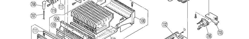
40 Internal Components 40
INSTALLATION AND OPERATING INSTRUCTION MANUAL
 TANKLESS GAS WATER HEATER FOR INTERIOR INSTALLATION IGI-180R AND IGI-180C MODEL SERIES WARNING: If the information in these instructions is not followed exactly, a fire or explosion may result causing
INSTALLATION AND OPERATION INSTRUCTION MANUAL With Troubleshooting Guide
 Bradford White EverHot Condensing Tankless Gas Water Heater For Exterior Installation TGHE-160E-N(X) and TGHE-199E-N(X) WARNING: If the information in these instructions is not followed exactly, a fire
STAINLESS STEEL INDIRECT-FIRED WATER HEATER
 STAINLESS STEEL INDIRECT-FIRED WATER HEATER A Spanish language version of these instructions is available by contacting the manufacturer listed on the rating plate. La version Espanola de estas instruccions
GAS-FIRED COMMERCIAL WATER HEATER
 GAS-FIRED COMMERCIAL WATER HEATER WARNING: If the information in these instructions is not followed exactly, a fire or explosion may result causing property damage, personal injury or death - Do not store
Internet Version for Reference Only STORAGE UNIT
 STORAGE UNIT A Spanish language version of these instructions is available by contacting the manufacturer listed on the rating plate. La version espanola de estas instrucciones se puede obtener al escribirle
TWO GALLON ELECTRIC WATER HEATER INSTALLATION & OPERATING INSTRUCTION MANUAL
 TWO GALLON ELECTRIC WATER HEATER A Spanish language version of these instructions is available by contacting the manufacturer listed on the rating plate. La version Espanola de estas instrucctions se puede
POWERED DIRECT VENT SERIES GAS-FIRED COMMERCIAL WATER HEATER (INDEPENDENT PVC VENTING)
") POWERED DIRECT VENT SERIES GAS-FIRED COMMERCIAL WATER HEATER (INDEPENDENT PVC VENTING) WARNING: If the information in these instructions is not followed exactly, a fire or explosion may result causing
POWERED DIRECT VENT SERIES GAS-FIRED COMMERCIAL WATER HEATER (INDEPENDENT PVC VENTING) WARNING: If the information in these instructions is not followed exactly, a fire or explosion may result causing
INSTALLATION & SERVICE MANUAL
 GAS-FIRED WATER HEATER If the information in these instructions is not followed exactly, a fire or explosion may result causing property damage, personal injury or death. INSTALLATION & SERVICE MANUAL
INDIRECT-FIRED WATER HEATER
 INDIRECT-FIRED WATER HEATER A Spanish language version of these instructions is available by contacting the manufacturer listed on the rating plate. La version espanola de estas instruccions se puede obtener
LGB Gas fired boiler
 LGB Gas fired boiler Control Supplement LGB-5 Series 2 Propane gas CSD-1 Control System Part Number 550-110-682/0304 Please read this page first Hazard definitions To the installer... The following terms
GAS-FIRED WATER HEATER
 GAS-FIRED WATER HEATER A Spanish language version of these instructions is available by contacting the company listed on the rating plate. La version Espanola de estas instrucciones se puede obtener al
INTERNET VERSION FOR REFERENCE ONLY
 DIRECT VENT GAS WATER HEATER A Spanish language version of these instructions is available by contacting the company listed on the rating plate. La version espanola de estas instrucciones se puede obtener
User s Information Manual
 User s Information Manual Gas-Fired Storage Water Heater, Tankless Water Heater, Heating Appliance, and Combination Appliance Models IF THE INFORMATION IN THIS MANUAL IS NOT FOLLOWED EXACTLY, A FIRE OR
H 2. Hot Water Storage/ Booster Tanks. For Single Tank Installations INSTALLATION, OPERATION & MAINTENANCE MANUAL
 H 2 O Hot Water Storage/ Booster Tanks For Single Tank Installations INSTALLATION, OPERATION & MAINTENANCE MANUAL 30, 40, 60, 80, 115 Gallon L = Low Boy Profile C = Commercial Pipe Connections Conforms
INDIRECT-FIRED WATER HEATER
 INDIRECT-FIRED WATER HEATER A Spanish language version of these instructions is available by contacting the manufacturer listed on the rating plate. La version espanola de estas instruccions se puede obtener
GAS-FIRED WATER HEATER
 GAS-FIRED WATER HEATER A Spanish language version of these instructions is available by contacting the company listed on the rating plate. La version Espanola de estas instrucciones se puede obtener al
INSTALLATION & OPERATING INSTRUCTION MANUAL
 ELECTRIC-WALL MOUNTED WATER HEATER A Spanish language version of these instructions is available by contacting the manufacturer listed on the rating plate. La version espanola de estas instruccions se
GAS-FIRED WATER HEATER
 GAS-FIRED WATER HEATER A Spanish language version of these instructions is available by contacting the company listed on the rating plate. La versión espãnola de estas instrucciones se puede obtener al
GAS-FIRED WATER HEATER
 GAS-FIRED WATER HEATER A Spanish language version of these instructions is available by contacting the company listed on the rating plate. La versión espãnola de estas instrucciones se puede obtener al
GAS-FIRED WATER HEATER
 GAS-FIRED WATER HEATER A Spanish language version of these instructions is available by contacting the company listed on the rating plate. La version Espanola de estas instrucciones se puede obtener al
GAS-FIRED WATER HEATER
 GAS-FIRED WATER HEATER A Spanish language version of these instructions is available by contacting the company listed on the rating plate. La version Espanola de estas instrucciones se puede obtener al
LGB. Control Supplement. Gas fired boiler. Universal Control System. Series 2 Propane gas. Contents
 LGB Gas fired boiler Control Supplement LGB-6 to LGB-23 Series 2 Propane gas Universal Control System Contents I. New installation... 2 II. Existing installation... 4 III. Gas piping... 5 IV. Wiring...
ELECTRIC WATER HEATER INSTALLATION & OPERATING INSTRUCTION MANUAL
 ELECTRIC WATER HEATER A Spanish language version of these instructions is available by contacting the manufacturer listed on the rating plate. La version espanola de estas instruccions se puede obtener
GAS-FIRED WATER HEATER
 GAS-FIRED WATER HEATER A Spanish language version of these instructions is available by contacting the company listed on the rating plate. La version espanola de estas instrucciones se puede obtener al
POWER VENTED GAS WATER HEATER INSTALLATION AND OPERATING INSTRUCTION MANUAL
 POWER VENTED GAS WATER HEATER A Spanish language version of these instructions is available by contacting the company listed on the rating plate. La version espanola de estas instrucciones se puede obtener
DIRECT VENT GAS WATER HEATER
 DIRECT VENT GAS WATER HEATER A Spanish language version of these instructions is available by contacting the company listed on the rating plate. La versión espãnola de estas instrucciones se puede obtener
LIGHT DUTY COMMERCIAL ELECTRIC WATER HEATER INSTALLATION & OPERATING INSTRUCTION MANUAL
 LIGHT DUTY COMMERCIAL ELECTRIC WATER HEATER A Spanish language version of these instructions is available by contacting the company listed on the rating plate. La versión espãnola de estas instrucciones
POWER VENTED GAS WATER HEATER INSTALLATION AND OPERATING INSTRUCTION MANUAL
 POWER VENTED GAS WATER HEATER A Spanish language version of these instructions is available by contacting the company listed on the rating plate. La version espanola de estas instrucciones se puede obtener
GAS-FIRED WATER HEATER
 GAS-FIRED WATER HEATER A Spanish language version of these instructions is available by contacting the company listed on the rating plate. La version Espanola de estas instrucciones se puede obtener al
MANUFACTURED HOME (MOBILE HOME) CLOSED COMBUSTION (DIRECT VENTING) INSTALLATION AND OPERATING INSTRUCTION MANUAL
 CLOSED COMBUSTION (DIRECT VENTING) INSTALLATION AND OPERATING INSTRUCTION MANUAL") GAS WATER HEATER A Spanish language version of these instructions is available by contacting the company listed on the rating plate. La versión espãnola de estas instrucciones se puede obtener al escribirle
GAS WATER HEATER A Spanish language version of these instructions is available by contacting the company listed on the rating plate. La versión espãnola de estas instrucciones se puede obtener al escribirle
INSTALLATION & SERVICE MANUAL
 INSTALLATION & SERVICE MANUAL ELECTRIC WATER HEATER THE WARRANTY ON THIS WATER HEATER IS IN EFFECT ONLY WHEN THE WATER HEATER IS INSTALLED AND OPERATED IN ACCORDANCE WITH LOCAL CODES AND THESE INSTRUCTIONS.
COMMERCIAL ELECTRIC WATER HEATER INSTALLATION & OPERATION INSTRUCTION MANUAL
 COMMERCIAL ELECTRIC WATER HEATER A Spanish language version of these instructions is available by contacting the company listed on the rating plate. La versión espãnola de estas instrucciones se puede
GAS-FIRED WATER HEATER
 GAS-FIRED WATER HEATER A Spanish language version of these instructions is available by contacting the company listed on the rating plate. La version Espanola de estas instrucciones se puede obtener al
INSTALLATION AND OPERATING INSTRUCTION MANUAL
 POWERED DIRECT VENT GAS WATER HEATER A Spanish language version of these instructions is available by contacting the company listed on the rating plate. La version espanola de estas instrucciones se puede
SOLAR WATER HEATER WITH ELECTRIC BACKUP
 SOLAR WATER HEATER WITH ELECTRIC BACKUP A Spanish language version of these instructions is available by contacting the manufacturer listed on the rating plate. La version espanola de estas instruccions
ELECTRIC WATER HEATER INSTALLATION & OPERATING INSTRUCTION MANUAL
 ELECTRIC WATER HEATER INSTALLATION & OPERATING INSTRUCTION MANUAL THE MANUFACTURER OF THIS HEATER WILL NOT BE LIABLE FOR ANY DAMAGE RESULTING FROM FAILURE TO COMPLY WITH THESE INSTRUCTIONS. READ THESE
OPERATING INSTRUCTIONS AND OWNER S MANUAL
 OPERATING INSTRUCTIONS AND OWNER S MANUAL MR. HEATER READ INSTRUCTIONS CAREFULLY: Read and follow all instructions. Place instructions in a safe place for future reference. Do not allow anyone who has
GAS COOKTOP INSTALLATION INSTRUCTIONS
 INSTALLATION AND SERVICE MUST BE PERFORMED BY A QUALIFIED INSTALLER. IMPORTANT: SAVE FOR LOCAL ELECTRICAL INSPECTOR'S USE. READ AND SAVE THESE INSTRUCTIONS FOR FUTURE REFERENCE. WARNING If the information
Installation & Operation Manual Models: TSU
 TSU-I-O Rev A Installation & Operation Manual Models: TSU 150-940 CAUTION: This appliance is not intended for potable water. This manual must only be used by a qualified heating installer / service technician.
CYLINDER NOT INCLUDED
 OPERATING INSTRUCTIONS AND OWNER S MANUAL Model # HS125NG / MH125LP / HS125LP READ INSTRUCTIONS CAREFULLY: Read and follow all instructions. Place instructions in a safe place for future reference. Do
Installer: Leave this manual with the appliance. Consumer: Retain this manual for future reference.
 Installer: Leave this manual with the appliance. Consumer: Retain this manual for future reference. Operating Instructions and Owner s Manual READ INSTRUCTIONS CAREFULLY: Read and follow all instructions.
Use & Care Manual. Electric Tankless Water Heaters. With Installation Instructions for the Installer AP15447 (10/10)
") Use & Care Manual With Installation Instructions for the Installer Electric Tankless Water Heaters The purpose of this manual is twofold: one, to provide the installer with the basic directions and recommendations
Use & Care Manual With Installation Instructions for the Installer Electric Tankless Water Heaters The purpose of this manual is twofold: one, to provide the installer with the basic directions and recommendations
POWER VENT GAS WATER HEATER INSTALLATION AND OPERATION INSTRUCTION MANUAL
 POWER VENT GAS WATER HEATER A Spanish language version of these instructions is available by contacting the company listed on the rating plate. La version espanola de estas instrucciones se puede obtener
GAS COOKTOP INSTALLATION INSTRUCTIONS BEFORE YOU BEGIN. IMPORTANT Save these instructions for local electrical inspector s use.
 GAS COOKTOP INSTALLATION INSTRUCTIONS Please read this guide thoroughly before installation. To contact LG Electronics, 24 hours a day, 7 days a week: 1-800-243-0000 (U.S.A.) 1-888-542-2623 (Canada) Or
INSTALLATION GUIDE Dual Fuel Ranges
 INSTALLATION GUIDE Dual Fuel Ranges Contents Wolf Dual Fuel Ranges......................... 3 Safety Instructions............................ 4 Dual Fuel Range Specifications.................. 5 Dual Fuel
User s Information Manual Models: 45, ,000 Btu/hr
 SBR-USER_100161678_2000017137_Rev C User s Information Manual Models: 45,000-260,000 Btu/hr If the information in this manual is not followed exactly, a fire or explosion may result causing property damage,
POWER VENT GAS WATER HEATER
 POWER VENT GAS WATER HEATER A Spanish language version of these instructions is available by contacting the company listed on the rating plate. La version espanola de estas instrucciones se puede obtener
Tankless Water Heater
 Tankless Water Heater USER S INFORMATION MANUAL Models WGRT**150 / WGRT**199 / WGRTC**199 **A suffix of LP denotes propane gas **A suffix of NG denotes natural gas NOTICE: Westinghouse reserves the right
POWER VENT GAS WATER HEATER
 POWER VENT GAS WATER HEATER A Spanish language version of these instructions is available by contacting the company listed on the rating plate. La version espanola de estas instrucciones se puede obtener
DAMPER EQUIPPED GAS WATER HEATER
 DAMPER EQUIPPED GAS WATER HEATER A Spanish language version of these instructions is available by contacting the company listed on the rating plate. La version espanola de estas instrucciones se puede
Stone Hearth Pizza Dome Oven
 Stone Hearth Pizza Dome Oven INSTALLATION AND OPERATION MANUAL GAS-FIRED OVEN CAUTION This oven MUST be seasoned before initial use The seasoning procedure takes 6 days, running the oven for at least 8
Sun Bandit Hybrid Water Heater Installation and Operation Solar Hybrid Energy Systems Patent(s) Pending
 Pending") Solar Hybrid Energy Systems Patent(s) Pending Sun Bandit Hybrid Water Heater Installation and Operation Solar Hybrid Energy Systems Patent(s) Pending Instruction Manual Solar Hybrid Energy Systems Patent(s)
Solar Hybrid Energy Systems Patent(s) Pending Sun Bandit Hybrid Water Heater Installation and Operation Solar Hybrid Energy Systems Patent(s) Pending Instruction Manual Solar Hybrid Energy Systems Patent(s)
USER S INFORMATION MANUAL
 USER S INFORMATION MANUAL UPFLOW & DOWNFLOW/HORIZONTAL CONDENSING GAS FURNACES SAFETY Recognize this symbol as an indication of Important Safety Information If not installed, operated and maintained in
STORAGE UNIT AST-40, AST-50, AST-80, AST-120 INSTALLATION & OPERATING INSTRUCTION MANUAL
 STORAGE UNIT AST-40, AST-50, AST-80, AST-120 A Spanish language version of these instructions is available by contacting the manufacturer listed on the rating plate. La version espanola de estas instrucciones
SuperStor Ultra Stainless Steel Storage Tank
 SuperStor Ultra Stainless Steel Storage Tank INSTALLATION START-UP MAINTENANCE PARTS Storage Tank Models SSU-30CB / SSU-45CB SSU-60CB / SSU-80CB / SSU-119CB For Residential and Commercial Use This manual
Residential Gas Hybrid Water Heater
 Residential Gas Hybrid Water Heater USER S INFORMATION MANUAL WGRGH20NG75F / WGRGH20NG76F / WGRGH20NG100F WGRGHNG75F / WGRGHNG76F / WGRGHNG100F Models* *A suffix of LP denotes propane gas NOTICE: Westinghouse
INSTALLATION AND OPERATING INSTRUCTION MANUAL
 POWERED DIRECT VENT GAS WATER HEATER A Spanish language version of these instructions is available by contacting the company listed on the rating plate. La version espanola de estas instrucciones se puede
Installation Instructions Dual Fuel Ranges
 Installation Instructions Dual Fuel Ranges E30DF74EPS E36DF76EPS E48DF76EPS 5995447082 2 Safety IMPORTANT SAFETY INSTRUCTIONS Safety Precautions Do not attempt to install or operate your unit until you
OPERATING INSTRUCTIONS MANUAL (Please retain for future reference) F-1500T DUAL FUEL CONSTRUCTION HEATER
 F-1500T DUAL FUEL CONSTRUCTION HEATER") OPERATING INSTRUCTIONS MANUAL (Please retain for future reference) For F-1500T DUAL FUEL CONSTRUCTION HEATER CERTIFIED FOR USE IN CANADA AND U.S.A. As per Standard ANSI Z83.7 2000/ CSA 2.14 2000 Gas Fired
OPERATING INSTRUCTIONS MANUAL (Please retain for future reference) For F-1500T DUAL FUEL CONSTRUCTION HEATER CERTIFIED FOR USE IN CANADA AND U.S.A. As per Standard ANSI Z83.7 2000/ CSA 2.14 2000 Gas Fired
Using it in an enclosed space can kill you.
 38 X 56 GAS FIRE PIT - OWNER S MANUAL Carlisle Chat Fire Table Base Model # 00GBC7 (6877B) Fits 6877A Carlisle Chat Fire Table Top For Propane and *Natural Gas (*See Page 7) Certified to CSA International
CBO-750 HYBRID-R OVEN Instructions Manual
 CBO-750 HYBRID-R OVEN Instructions Manual ELECTRICAL DIAGRAM IS LOCATED BEHIND FRONT PANEL THIS OVEN MAY BE OPERATED OUTDOORS. ELECTRICAL DIAGRAMS ARE LOCATED BEHIND FRONT PANEL. KEEP THIS MANUAL FOR FUTURE
User s Information Manual Models: ER152, ER202, ER252, ER302, and ER402
 ERP-USER_100161005_2000003726_Rev D User s Information Manual Models: ER152, ER202, ER252, ER302, and ER402 If the information in this manual is not followed exactly, a fire or explosion may result causing
OPERATING INSTRUCTIONS MANUAL (Please retain for future reference) F-400T DUAL FUEL CONSTRUCTION HEATER
 F-400T DUAL FUEL CONSTRUCTION HEATER") OPERATING INSTRUCTIONS MANUAL (Please retain for future reference) For F-400T DUAL FUEL CONSTRUCTION HEATER CERTIFIED FOR USE IN CANADA AND U.S.A. As per Standard ANSI Z83.7 2000/ CSA 2.14 2000 Gas Fired
OPERATING INSTRUCTIONS MANUAL (Please retain for future reference) For F-400T DUAL FUEL CONSTRUCTION HEATER CERTIFIED FOR USE IN CANADA AND U.S.A. As per Standard ANSI Z83.7 2000/ CSA 2.14 2000 Gas Fired
Installation Instructions
 Installation Instructions Gas & Electric Dryer Before beginning installation, carefully read these instructions. This will simplify the installation and ensure the dryer is installed correctly and safely.
Universal Fire Tube Boiler Wall Mount Models
 Universal Fire Tube Boiler Wall Mount Models USER S INFORMATION MANUAL Models WBRU**80W / 100W / 120W / 140W / 175W / 199W **NG denotes Natural Gas Model, LP Denotes Propane Model Heat Exchanger Bears
POWER VENT GAS WATER HEATER
 POWER VENT GAS WATER HEATER A Spanish language version of these instructions is available by contacting the company listed on the rating plate. La version espanola de estas instrucciones se puede obtener
INSTALLATION & OPERATION MANUAL WITH TROUBLESHOOTING GUIDE
 ULTRA HIGH EFFICIENCY COMMERCIAL GAS WATER HEATER WARNING If the information in these instructions is not followed exactly, a fire or explosion may result causing property damage, personal injury or death.
Internet Version for Reference Only INDUCED DRAFT COMMERCIAL WATER HEATERS SUPPLEMENT INSTRUCTIONS TO PART #
 INDUCED DRAFT COMMERCIAL WATER HEATERS SUPPLEMENT INSTRUCTIONS TO PART #238-39387-00 THIS INSTRUCTION SUPPLEMENT IS ONLY INTENDED TO GIVE INSTALLATION INSTRUCTIONS AND INFORMATION RELATED TO THE INDUCED
OPERATING INSTRUCTIONS MANUAL (Please retain for future reference) F-1000T DUAL FUEL CONSTRUCTION HEATER
 F-1000T DUAL FUEL CONSTRUCTION HEATER") OPERATING INSTRUCTIONS MANUAL (Please retain for future reference) For F-1000T DUAL FUEL CONSTRUCTION HEATER CERTIFIED FOR USE IN CANADA AND U.S.A. As per Standard ANSI Z83.7 2000/ CSA 2.14 2000 Gas Fired
OPERATING INSTRUCTIONS MANUAL (Please retain for future reference) For F-1000T DUAL FUEL CONSTRUCTION HEATER CERTIFIED FOR USE IN CANADA AND U.S.A. As per Standard ANSI Z83.7 2000/ CSA 2.14 2000 Gas Fired
GAS COOKTOP MODELS: CTG365D, CTG305D, CTG304D TO REDUCE THE RISK OF FIRE, ELECTRIC SHOCK, OR INJURY TO PERSONS, OBSERVE THE FOLLOWING
 By CNP INDUSTRIES, INC. P.O. Box 18645 Anaheim, Ca 92817 (877) 387-6721 INSTALLATION INSTRUCTIONS GAS COOKTOP MODELS: CTG365D, CTG305D, CTG304D IMPORTANT: Before beginning installation please read these
USER S INFORMATION MANUAL
 USER S INFORMATION MANUAL UPFLOW/HORIZONTAL & DOWNFLOW TWO STAGE INDUCED DRAFT GAS FURNACES Recognize this symbol as an indication of Important Safety Information If the information in this manual is not
MODELS LFP4218/LFP6018 TOP VENT GAS FIREPLACE
 MODELS LFP4218/LFP6018 TOP VENT GAS FIREPLACE PFS APPROVED FOR NATURAL GAS OR PROPANE GAS Z21.50-2014 If your plans do not allow for the venting system as outlined previously in the installing chimney/vent
INDIRECT FIRED WATER HEATERS
 H E A T T R A N S F E R P R O D U C T S INDIRECT FIRED WATER HEATERS RESIDENTIAL COMMERCIAL Heat Transfer Products, Inc., reserves the right to make product changes or updates without notice. Heat Transfer
POWER VENT GAS WATER HEATER INSTALLATION AND OPERATION INSTRUCTION MANUAL
 POWER VENT GAS WATER HEATER A Spanish language version of these instructions is available by contacting the company listed on the rating plate. La version espanola de estas instrucciones se puede obtener
SUPER HIGH EFFICIENCY WATER HEATERS SUPPLEMENT TO INSTRUCTION MANUAL P/N (Replaces pg. 2 in instruction manual.) CONGRATULATIONS!
 CONGRATULATIONS!") SUPER HIGH EFFICIENCY WATER HEATERS SUPPLEMENT TO INSTRUCTION MANUAL P/N 238-44219-00 (Replaces pg. 2 in instruction manual.) CONGRATULATIONS! You have just purchased one of the finest water heaters on
SUPER HIGH EFFICIENCY WATER HEATERS SUPPLEMENT TO INSTRUCTION MANUAL P/N 238-44219-00 (Replaces pg. 2 in instruction manual.) CONGRATULATIONS! You have just purchased one of the finest water heaters on
POWER DIRECT VENT GAS WATER HEATER
 POWER DIRECT VENT GAS WATER HEATER A Spanish language version of these instructions is available by contacting the company listed on the rating plate. La version espanola de estas instrucciones se puede
User s Information Manual
 Gas-fired Water boiler Series 2 NOTICE: Series 1/Series 2 identification Read the boiler rating plate to determine the series number. The rating plate is located on the right side of the boiler. User s
SuperStor Glass Lined Storage Tank
 SuperStor Glass Lined Storage Tank INSTALLATION MAINTENANCE TROUBLESHOOTING PARTS Storage Tank Models GL-50 / GL-80* GL-119* / GL-175* For Residential and Commercial Use *Available in Metal Jacketed ASME
Installation & Operation Manual Models: SIT030, SIT040, SIT050, SIT065, SIT080, & SIT119
 SIT-I-O Rev B Installation & Operation Manual Models: SIT030, SIT040, SIT050, SIT065, SIT080, & SIT119 WARNING This manual must only be used by a qualified heating installer / service technician. Read
SuperStor Contender Indirect Fired Water Heater
 SuperStor Contender Indirect Fired Water Heater INSTALLATION START-UP MAINTENANCE PARTS SuperStor Contender Water Heater Models SSC-35 / SSC-50 / SSC-80 / SSC-119* *NOTE: A suffix of S denotes Solar Model
INSTALLATION INSTRUCTIONS FOR FREESTANDING DUAL FUEL
 INSTALLATION AND SERVICE MUST BE PERFORMED BY A QUALIFIED INSTALLER. IMPORTANT: SAVE FOR LOCAL ELECTRICAL INSPECTOR'S USE. READ AND SAVE THESE INSTRUCTIONS FOR FUTURE REFERENCE. If the information in this
Multi-Function Cooktop
 INSTALLATION GUIDE Multi-Function Cooktop Contents Wolf Multi-Function Cooktop.................... 3 Multi-Function Cooktop Specifications............ 4 Multi-Function Cooktop Installation...............
Installation Guide. 5 Series VGC and VGSU Built-In Gas Cooktops
 Installation Guide 5 Series VGC and VGSU Built-In Gas Cooktops Table of Contents Warnings & Important Safety Instructions 3 Dimensions VGC Cooktops 6 Specifications VGC Cooktops 7 Dimensions VGSU Cooktops
For use with models: PGM304-1, versions M-B PGM365-1, versions M-E, M-F & M-G
 PGM-1 Cooktops For use with models: PGM304-1, versions M-B PGM365-1, versions M-E, M-F & M-G Install ation Instructions Part No. 65476 Rev. B Table of Contents Appliance Safety...1 Important Safety Instructions...2
INSTALLATION AND OPERATION MANUAL GAS SKILLETS MODELS: GTS-30 GTS-40
 INSTALLATION AND OPERATION MANUAL GAS SKILLETS MODELS: GTS-30 GTS-40 CROWN FOOD SERVICE EQUIPMENT LTD. 70 OAKDALE ROAD, DOWNSVIEW, (TORONTO), ONTARIO, CANADA, M3N 1V9 TELEPHONE: (416) 746-2358, FAX: (416)
TANKLESS WATER HEATER USE AND CARE MANUAL
 WARNING: If the information in these instructions is not followed exactly, a fire or explosion may result, causing death, personal injury, or property damage. For Your Safety! Do not store or use gasoline
SAFE DRINKING WATER AND TOXIC ENFORCEMENT ACT
 Installation instructions for your new Spacemaker Laundry WSM2780 Gas Before you begin Read these instructions completely and carefully. IMPORTANT OBSERVE ALL GOVERNING CODES AND ORDINANCES. Note to Installer
USER S INFORMATION MANUAL Model: HSE 125 N/P, HSE 145 N/P Gas-fired, Condensing Boiler and Instantaneous Water Heater
 USER S INFORMATION MANUAL Model: HSE 125 N/P, HSE 145 N/P Gas-fired, Condensing Boiler and Instantaneous Water Heater Contents Section Page Major Components... 2 1 About Our Manual... 2 2 Refractory Handling...
Gas Fired Residential Combi Boiler Floor and Wall Mount Models
 Gas Fired Residential Combi Boiler Floor and Wall Mount Models USER S INFORMATION MANUAL Models WBRC**140W WBRC**199W WBRC**140F WBRC**199F ** NG Refers to Natural Gas Operation LP Refers to Propane Gas
ASME COMMERCIAL ELECTRIC WATER HEATER INSTALLATION & OPERATING INSTRUCTION MANUAL
 ASME COMMERCIAL ELECTRIC WATER HEATER A Spanish language version of these instructions is available by contacting the company listed on the rating plate. La versión espãnola de estas instructiones se puede
TO DO IF YOU SMELL GAS
 User's Information Document 1125B User's Information Manual for Endurance EBP Series Modulating Combination Boiler (natural or propane gas) EDP Series Modulating Hydronic Boiler (natural or propane gas)
INSTALLATION AND OPERATION MANUAL STEAM COIL BASE CONVECTION STEAMER MODEL SCX-16
 INSTALLATION AND OPERATION MANUAL STEAM COIL BASE CONVECTION STEAMER MODEL SCX-16 CROWN FOOD SERVICE EQUIPMENT LTD. 70 OAKDALE ROAD, DOWNSVIEW, (TORONTO), ONTARIO, CANADA, M3N 1V9 TELEPHONE: (416) 746-2358,
POWER VENT GAS WATER HEATER
 POWER VENT GAS WATER HEATER A Spanish language version of these instructions is available by contacting the company listed on the rating plate. La version espanola de estas instrucciones se puede obtener
USER S INFORMATION MANUAL
 USER S INFORMATION MANUAL UPFLOW & DOWNFLOW/HORIZONTAL TWO-STAGE SAFETY CONDENSING GAS FURNACES Recognize this symbol as an indication of Important Safety Information IMPORTANT: All manufacturer products
OWNERS MANUAL INSTALLATION, OPERATION, & MAINTENANCE INSTRUCTIONS
 OWNERS MANUAL INSTALLATION, OPERATION, & MAINTENANCE INSTRUCTIONS 1128 Sherborn Street Corona, CA 92879-2089 (951) 281-1830 (951) 281-1879 IPC SERIES PASTA COOKER All Imperial Mfg. Co. equipment is manufactured
Installation Instructions
 Installation Instructions for Dryers Inside... Dimensions... Before You Start... 4 Installing the Dryer... 5 Installer Checklist... Back Cover Date Purchased Model Number Serial Number Keep these instructions
Installation Instructions
 Instructions for Stacked Dryers Original Instructions Keep These Instructions for Future Reference. (If this machine changes ownership, this manual must accompany machine.) www.speedqueen.com Part No.
Mighty Venter Power Vent System
 Installation and Operation Instructions Document 7008B Installation and Operation Instructions for Mighty Venter Power Vent System Models MV2, MV3, MV4, and MV5 for Mighty Therm Sizes 500-1825 FOR YOUR
Installation Instructions T 9822 Gas Dryer. en - US, CA. To prevent accidents
 Installation Instructions T 9822 Gas Dryer To prevent accidents en - US, CA and appliance damage read these instructions before installation or use. M.-Nr. 07 431 110 2 WARNING For your safety the information
Conversion Instructions Logano G234X. Gas boiler. Please read carefully before installing and servicing. Gas boiler
 Gas boiler UPON COMPLETION OF THE INSTALLATION THE INSTALLER MUST INSTRUCT THE OWNER AND OPERATOR ON THE FUNCTIONALITY AND THE PROPER OPERATION OF THE BOILER AND THE HEATING SYSTEM. INSTALLER MUST REVIEW