T-SERIES. Window & Roof Models. Installation, Set-up and Operating Instructions. 230V/1/50Hz
|
|
|
- Charles Martin
- 5 years ago
- Views:
Transcription
1 T-SERIES Window & Roof Models Installation, Set-up and Operating Instructions Stock Ref. Nos. WIRED A (9" WW) A (9" RF) A (12" WW) A (12" RF) WIRELESS A (9" WW) A (9" RF) A (12" WW) A (12" RF) 230V/1/50Hz READ INSTRUCTIONS IN CONJUNCTION WITH ILLUSTRATIONS READ AND SAVE THESE INSTRUCTIONS (Community Design Nos & )


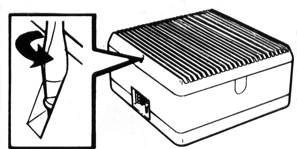
2 READ INSTRUCTIONS IN CONJUNCTION WITH THE ILLUSTRATIONS IMPORTANT 1. THE FAN MUST BE SITED AND CONNECTED IN ACCORDANCE WITH CURRENT IEE REGULATIONS (UK) OR THE APPROPRIATE STANDARDS IN YOUR COUNTRY. 2. THIS APPLIANCE IS NOT SUITABLE FOR INSTALLATION IN A SHOWER CUBICLE OR ENCLOSURE AND MUST BE SITED AWAY FROM ANY SOURCE OF WATER SPRAY, AND MUST BE OUT OF REACH OF A PERSON USING A FIXED BATH OR SHOWER. 3. SITE AWAY FROM DIRECT SOURCES OF HEAT IN EXCESS OF 50ºC OR LESS THAN 10ºC. 4. WHEN THE FAN IS INSTALLED IN A ROOM CONTAINING A FUEL BURNING APPLIANCE, THE INSTALLER MUST ENSURE THAT AIR REPLACEMENT IS ADEQUATE FOR BOTH THE FAN AND THE FUEL BURNING APPLIANCE. 5. IF THE FAN CAN BE USED TO SUPPLY AIR INTO THE ROOM THE INSTALLER MUST ENSURE THAT THE FAN INTAKE IS LOCATED AT LEAST 600MM AWAY FROM ANY FLUE OUTLET. 6. IT IS RECOMMENDED THAT THE CONNECTION TO THE CONNECTOR SOCKET IS MADE WITH FLEXIBLE CABLE FOR EASY MAINTENANCE. 7. WIRING SHOULD BE VIA A SWITCHED SPUR WITH A 3 AMP FUSE (UK ONLY). 8. DOUBLE POLE SWITCH WITH A MINIMUM CONTACT SEPARATION OF 3MM OR PLUG AND SOCKET SHOULD BE LOCATED OUTSIDE OF A ROOM CONTAINING A FIXED BATH OR SHOWER. 9. THIS APPLIANCE MUST BE EARTHED. 10. READ THESE INSTRUCTIONS FULLY BEFORE COMMENCING INSTALLATION. 11. THE APPLIANCE IS NOT INTENDED FOR USE BY YOUNG CHILDREN OR INFIRM PERSONS WITHOUT SUPERVISION. 12. YOUNG CHILDREN SHOULD BE SUPERVISED TO ENSURE THAT THEY DO NOT PLAY WITH THE APPLIANCE. 13. A SHORT CIRCUIT OF THE AIR FLOW SHOULD ALWAYS BE AVOIDED BY SITING THE FAN AS FAR AWAY AS POSSIBLE FROM AND OPPOSITE TO THE MAIN SOURCE OF AIR REPLACEMENT. B1/ 2 B1/ 2 Fig. 1 SPEED CONTROLLER CONNECTION SOCKET (WIRED VERSION ONLY) POWER SUPPLY/ RECEIVER UNIT CONNECTOR SOCKET MOTOR BODY HOUSING HOUSING INDOOR GRILLE ROOF COWL SHUTTER ACTUATOR IMPELLER BASE OUTER GRILLE SECTION 2


3 FAN DIMENSIONS Before commencing work, study the tables shown in figures C1/ C2 to ensure fan will fit in position proposed. NB: Allow a minimum of 54mm above fan casing for withdrawal of connector socket. Please note that for all Roof Fan installations a suitable sealing compound must be used to seal the exterior roof cowl assembly to the glass/or roof plate, to ensure a weatherproof seal. D1 THICKNESS OF GLASS Fans can be fitted in most types of glass and fixing thickness up to 32mm, with the screws provided. When fixing thickness exceeds 32mm, the unit should be secured with Extended Fixing Rods. If the unit is to be installed in a location exposed to severe wind turbulence or in non-vertical panes, thicker glass will be required consult your nearest Vent-Axia Sales, Service and Distribution Centre. C1 C2 SIZE 9 12 A 39mm 41mm B 150mm 177mm C 304mm 381mm D 302mm 378mm EØ 260mm 337mm F 20mm 20mm G 54mm 54mm SIZE 9 12 A 136mm 171mm B 150mm 177mm C 304mm 381mm D 302mm 378mm EØ 260mm 337mm F 20mm 20mm G 400mm 500mm D1 PREPARATION FOR INSTALLATION E1 Place fan unit, impeller downwards, on a flat surface. Unscrew the grille-securing screw located at the top of the grille. E2 Remove grille. Partially unscrew the two safety catch screws on the face of the housing E3 Depress the side catches. E4 Lift off the housing. E5 Release the Power Supply/Receiver Unit catch, located at the bottom left of the motor body housing assembly. E5a Lift the Power Supply/ Receiver Unit until the second catch engages. Slide the speed controller connection socket from the housing (wired version only). E6 Ease back the motor support safety catch, located to the left of the connector socket opening. Rotate motor body housing anti-clockwise until the bayonet catch disengages. E7 Withdraw motor body housing and place with the impeller downwards. 3

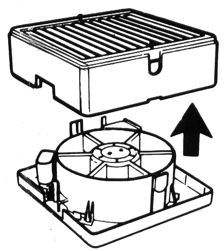
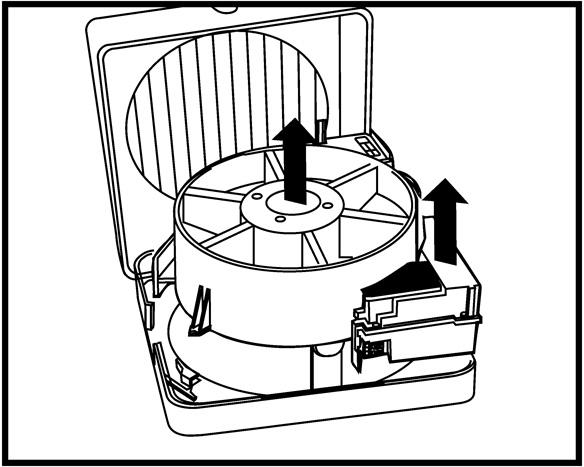
4 E1 E2 E3 E4 E5a E5 E6 E7 4

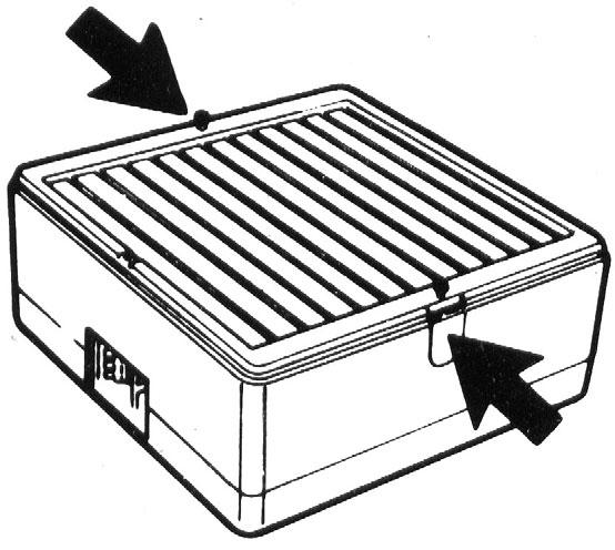
5 INSTALLATION F1 From the inside: Fit the spigot through the fixing hole, with the connector socket cut out at the top. Ensure that the rubber seal is correctly located over the four lugs on the spigot. F2i WINDOW From outside: Place the outdoor grille assembly with the louvres slanting downwards, and the Vent-Axia logo at the top of the grille, over the projecting spigot. F2ii ROOF From outside: Place the exterior roof cowl over the projecting spigot. Use a suitable sealing compound between the cowl and the glass/or roof plate. F3i/ ii Secure the outdoor grille or roof cowl, using the fixing screws supplied. Then tighten the screws in turn to give an even pressure around the hole. F4a/ b Refit the motor body housing assembly and turn clockwise until the locking catch is engaged. Take care not to trap the mains supply cable or the speed controller socket cable (wired version only). F5 Release the Power Supply/Receiver Unit locking catch and lower until the catch engages in the lower position, fix the controller socket into position (wired version only). F6 Lift the black rubber gasket on the Power Supply/Receiver Unit and switch the three-position switch to the required running option, then replace the gasket seal. F7 If a speed controller is being used refer to the relevant Speed Controller Fitting and Wiring instructions. F8 Refit the housing ensuring that no internal wires are trapped between the housing and base. F9 Engage the two side catches. Tighten the two side catch screws. F10 Replace the indoor grille with the louvres slanting upwards, with the Vent-Axia logo at the bottom of the grille, and secure with the retaining screw. F1 F2i F2ii 5


6 F3i/ ii F4a F5 F4b F7 FOR SPEED CONTROL F6 F9 REFER TO THE RELEVANT FITTING AND WIRING INSTRUCTIONS SUPPLIED WITH THE WIRED/ WIRELESS CONTROL. F10 6 F8


 CORRUGATED ROOF All T-Series roof models are suitable for fixing through corrugated sloped and vertical cladding using a suitable soaker flange.")
 FLAT ROOF All T-Series roof models may be installed through solid roofs using a roof plate assembly and, if required, an eggcrate grille or louvred grille in the ceiling below.")
7 TYPICAL ROOF INSTALLATIONS USING VENT-AXIA ACCESSORIES A (A) ROOF LIGHT All T-Series roof models are designed to fit directly into horizontal and sloping glass including wired cast and sealed double glazing up to 32mm thick. For materials of greater thicknesses extended fixing rod sets are available, allowing the unit to be fixed through a spacing of up to 370mm. Rod thread: 3.5mm Maximum fixing thickness: 370mm B (B) PITCHED ROOF All T-Series roof models may be installed in fixing plates with zinc or lead weathering apron (provided by others), fitted directly to a tiled or slated roof to provide a water-tight installation. A suitable sealing compound should be used between the weathering apron and the exterior unit seal The illustration shows a T-Series roof model fitted with a direct mount spigot and flexible ducting. C (C) CORRUGATED ROOF All T-Series roof models are suitable for fixing through corrugated sloped and vertical cladding using a suitable soaker flange. The soaker flange consists of a replacement sheet with a flat section to carry the unit. A suitable sealing compound should be used between the plate and the exterior unit seal. D (D) FLAT ROOF All T-Series roof models may be installed through solid roofs using a roof plate assembly and, if required, an eggcrate grille or louvred grille in the ceiling below. Alternatively, if ventilation is from a suspended ceiling, single spigots and flexible ducting may be used to connect the unit and extract grille. Roof plate assemblies are manufactured in high impact thermoplastic. A suitable sealing compound should be used between the plate and exterior unit seal. 7

8 WIRING THE CONNECTOR SOCKET Ensure that the supply (Voltage, Frequency and Phase) complies with the rating label. This appliance must be earthed. F11 Remove the top cover from the connector socket by undoing the 2 retaining screws. F12 Lift up lever and slide out top cover. F13 Loosen cable clamp screws and pass the cable through the clamp. (It may be necessary when using some 3-core cables to reverse the cable clamp to ensure that the cable is securely retained. For ease of wiring, the terminal block may be removed from the connector housing. F14 Tighten cable clamp screws evenly, ensuring a secure grip on the outer sheath of the cable. F15 Slide the top cover back on and secure with the 2 retaining screws. F16 Fit connector socket and push down on the lever to lock it in position. Fig 2 Using an On/Off switch: Connect the mains supply to the fan connector socket. Fig 3 Auxiliary sensor switching: Connect the mains supply to the fan connector socket. F11 F13 F12 F14 F16 F15 Fig. 2 (Wired version only) Please refer also to the speed controller fitting and wiring instructions. 8
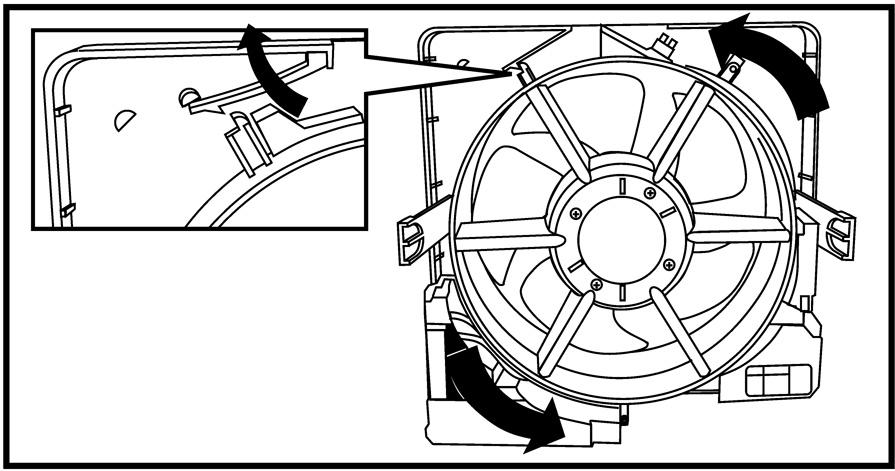
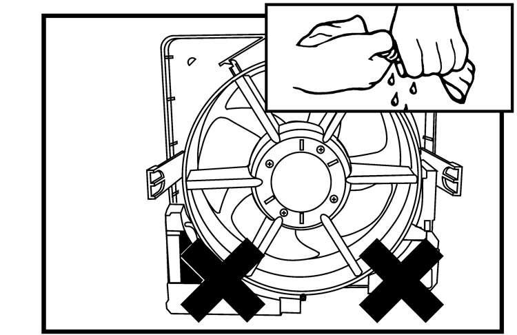
9 Fig. 3 (Wired version only) Please refer also to the speed controller fitting and wiring instructions. ISOLATE FROM THE POWER SUPPLY PRIOR TO ANY MAINTENANCE AND CLEANING USER INSTRUCTIONS At intervals appropriate to the installation, inspect and clean the fan to ensure there is no build up of grease or dirt on the impeller or the motor. The motor is fitted with sealed for life bearings and does not require lubrication. DISMANTLING G1 From the inside, remove the connector socket by lifting up the lever gently with a finger, unplug the controller cable (wired version only). G2 Unscrew the indoor grille retaining screw and remove the grille. G3 Partially unscrew the two side catch screws on the housing and depress the two side catches. G4 Remove the housing. G5a Release the Power Supply/Receiver Unit catch, located at the bottom left of the motor body housing assembly. G5b Lift the Power Supply/Receiver Unit until the second catch engages. Slide the controller socket from the housing (wired version only). G6 Release the motor body housing assembly locking catch located to the left of the connection socket opening and rotate the motor body housing assembly anti-clockwise until the bayonet catches disengage. G7 Withdraw the motor body housing assembly and put to one side, with the impeller facing upwards. G8 Remove the impeller with a sharp pull away from the motor. G9 Unscrew the outdoor grille retaining screw and remove the grille. CLEANING IMPORTANT: Keep all electrical components away from water. G10 Wipe the motor, housing assembly and roof cowl (if fitted) with a damp cloth. G11 Wash all non-electrical components in warm water and detergent. 9


.")
.")


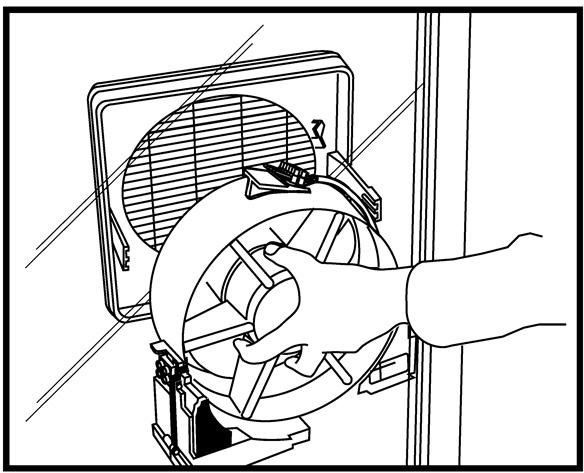
10 REASSEMBLY - ALLOW THE COMPONENTS TO DRY BEFORE REASSEMBLY G12 Replace the outdoor grille with the louvres slanting downwards, and the Vent-Axia logo at the top of the grille. Tighten the retaining screw located at the bottom of the grille. G13 Align the impeller with the locating pins on the motor shaft and refit the impeller with a sharp push. G14a/b Refit the motor body housing assembly and turn clockwise until the locking catch is engaged. Take care not to trap the speed controller socket cable (wired version only). G15 Release the Power Supply/Receiver Unit locking catch and lower until the catch engages in the lower position, fix the controller socket into position (wired version only). G16 Refit the housing ensuring that no internal wires are trapped between the housing and base. G17 Engage the two side catches. Tighten the two side catch screws. G18 Replace the indoor grille with the louvres slanting upwards and the Vent-Axia logo at the bottom of the grille, then secure with the retaining screw. G19 Replace the connector socket, push firmly into position and press the black locking peg down flush with the top of the connector socket. Plug the controller cable connector into the socket (wired version only). RECONNECT THE MAINS SUPPLY AND SWITCH THE UNIT ON. G2 G1 G3 G4 G5a G5b G6 G7 G8 G9 10


11 G10 G11 G12 G13 G14a G15 G14b G16 G17 G18 G19 11
12 VENT-AXIA SALES CENTRES ENGLAND & WALES NATIONAL CALL CENTRE SCOTLAND Newton Road, Crawley West Sussex Telephone: RH10 9JA Fax: Telephone: REPUBLIC OF IRELAND Fax: Vent-Axia Ventilation Ltd. 921 Western Road Industrial Estate NORTHERN IRELAND Naas Road, Dublin 12. Telephone: Telephone: (01) Fax: Fax: (01) Did you find these instructions easy to use? We value your comments, contact us via : info@vent-axia.com The Vent-Axia Guarantee Applicable only to products installed and used in the United Kingdom. For details of the Guarantee outside of the United Kingdom contact your local supplier. Vent-Axia guarantees this product for two years from the date of purchase against faulty material or workmanship. In the event of any part being found to be defective, the product will be repaired, or at the Company s discretion the product will be replaced without charge, provided that the product: 1). Has been installed and used in accordance with the instruction given with each unit. 2). The electricity supply complies with the rating label. 3). Has not been misused, neglected or damaged. 4). Has not been modified or repaired by any person not authorised to do so by Vent- Axia. IF CLAIMING UNDER THE TERMS OF THE GUARANTEE Please return the complete product, carriage paid to your original supplier by post or in person. Please ensure that it is adequately packed and accompanied by a letter clearly marked Guarantee Claim stating the nature of the fault and providing proof of the date and source of purchase. As part of the policy of continuous product improvement Vent-Axia reserve the right to alter specifications without notice Head Office: Fleming Way, Crawley, West Sussex RH10 9YX Tel: Fax: Internet site at: C
Lo-Carbon T-series Window & Roof Models
 Lo-Carbon T-series Window & Roof Models Installation & User Instructions WIRED 456165A (9 WW) 456168A (9 RF) 456173A (12 WW) 456176A (12 RF) WIRELESS 456169A (9 WW) 456172A (9 RF) 456177A (12 WW) 456180A
T-SERIES. Wall & Panel Models. Installation, Set-up and Operating Instructions. 230V/1/50Hz
 T-SERIES Wall & Panel Models Installation, Set-up and Operating Instructions Stock Ref. Nos. WIRED 456166A (9" WL) 456167A (9" PL) 456174A (12" WL) 456175A (12" PL) WIRELESS 456170A (9" WL) 456171A (9"
VA 150 A, VA 150 P WINDOW EXTRACT FAN. Installation and Wiring Instructions V/1/50Hz
 VA 150 A, VA 150 P WINDOW EXTRACT FAN Installation and Wiring Instructions VA150 P STOCK Ref: 152110B VA150 A STOCK Ref: 153110B 220-240V/1/50Hz READ INSTRUCTIONS IN CONJUNCTION WITH ILLUSTRATIONS PLEASE
PLEASE READ INSTRUCTIONS IN CONJUNCTION WITH ILLUSTRATIONS. PLEASE SAVE THESE INSTRUCTIONS.
 Eclipse Installation and Wiring Instructions Models Eclipse 100X Eclipse 100XP Eclipse 100XT Eclipse 150X Eclipse 150XP Ref No. 42 73 10A 42 72 81A 42 72 82A 42 72 83A 42 73 13A 220-240V~50Hz PLEASE READ
EKF. EC kitchen extract fan range. Installation and Wiring Instructions. Stock Ref. N EKF355E1 EKF400E1 EKF450E1 EKF450E3 EKF500E3 EKF560E3
 EKF EC kitchen extract fan range Installation and Wiring Instructions Stock Ref. N EKF355E1 EKF400E1 EKF450E1 EKF450E3 EKF500E3 EKF560E3 PLEASE READ INSTRUCTIONS IN CONJUNCTION WITH THE ILLUSTRATIONS.
EXTRACTOR HOOD. Please read all the instructions carefully before starting the installation. 230 / 240V 50Hz
 abc EXTRACTOR HOOD Please read all the instructions carefully before starting the installation Model Stock Ref Napoli 120812 Napoli Plus (white) 436083 Napoli Plus (Silver) 436084 230 / 240V 50Hz PLEASE
PLEASE READ INSTRUCTIONS IN CONJUNCTION WITH ILLUSTRATIONS.
 Silhouette Installation and Wiring Instructions Stock Ref. N 45 40 55B (100B) 44 51 61 (125B) 45 40 59B (150X) 45 40 56B (100T) 44 51 62 (125T) 45 40 60B (150XT) 45 40 57B (100HT) 44 51 63 (125HT) 45 40
Lo-Carbon Quadra SELV
 Lo-Carbon Quadra SELV Installation and Wiring Instructions Stock Ref. N Quadra SVTP 442865 Quadra SVHTP 442866 Quadra SVTM 442867 Safety Extra Low Voltage IPX7 PLEASE READ INSTRUCTIONS IN CONJUNCTION WITH
Lo-Carbon SELV Tempra
 Lo-Carbon SELV Tempra THROUGH THE WALL HEAT RECOVERY FAN Installation and Wiring Instructions DRAFT Stock Ref. N 444368 Pullcord. (SVP) 444369 Timer. (SVT) 444370 Humidistat -Timer Pullcord. (SVHTP) 220-240V~50Hz
Lo-Carbon Quadra Centrifugal Fan
 Lo-Carbon Quadra Centrifugal Fan Installation and Wiring Instructions Stock Ref. N Quadra TP Quadra TM Quadra HTP 439251A 439253A 439181A 220-240V~50Hz IPX4 PLEASE READ INSTRUCTIONS IN CONJUNCTION WITH
Centrif Duo & Centrif Duo Plus
 Centrif Duo & Centrif Duo Plus Installation and Wiring Instructions Stock Ref. N Centrif Duo P 25 61 20D Centrif Duo T 25 62 20D Centrif Duo DP 25 63 20D Centrif Duo HTP 25 64 20D Centrif Duo Centrif Duo
DUCT AIR HEATER WITH BUILT-IN CONTROLS. Installation & User Instructions. Stock Ref T T T3
 DUCT AIR HEATER WITH BUILT-IN CONTROLS Installation & User Instructions Stock Ref. 105 31 100 T1 105 31 125 T1 105 31 150 T1 105 31 200 T1 105 31 250 T1 105 31 315 T1 Stock Ref. 105 31 315 T3 105 31 400
PLEASE READ INSTRUCTIONS IN CONJUNCTION WITH ILLUSTRATIONS.
 VA100 Lo-Carbon RANGE 100mm AXIAL EXTRACT FAN Installation and Wiring Instructions Stock Ref. N 44 31 59 - LP 44 31 60 - XP 44 31 61 - LT 44 31 62 - XT 44 31 63 - LHTP 44 31 64 - XHTP 220-240V~50Hz PLEASE
PLEASE READ INSTRUCTIONS IN CONJUNCTION WITH ILLUSTRATIONS.
 Silhouette Lo-Carbon RANGE 100/150mm AXIAL EXTRACT FAN Installation and Wiring Instructions Stock Ref. N 44 16 24-100B 44 16 25-100T 44 16 26-100HT 44 16 28-150B 44 16 29-150T 44 16 30-150HT 220-240V~50Hz
Silhouette Installation and Wiring Instructions
 Silhouette Installation and Wiring Instructions Stock Ref. N 45 40 55B (100B) 44 51 61 (125B) 45 40 59B (150X) 45 40 56B (100T) 44 51 62 (125T) 45 40 60B (150XT) 45 40 57B (100HT) 44 51 63 (125HT) 45 40
SUPER T WALL FANS. Installation and Wiring Instructions
 SUPR T WALL FANS Installation and Wiring Instructions Stock Ref. N 16 10 16 6 10 16 7 10 16 8 10 - Gravity Shutter Version (6 Pole) 16 7 10 16 67 10 16 77 10 16 87 10 - lectric Shutter Version (6 Pole)
Lo-Carbon MULTIVENT MVDC-MS & MVDC-MS H VENTILATION SYSTEMS V~50Hz. Installation and Wiring Instructions IP22. Stock Ref.
 Lo-Carbon MULTIVENT MVDC-MS & VENTILATION SYSTEMS Installation and Wiring Instructions Stock Ref. N MVDC-MS 76A 98 0-0V~50Hz PLEASE READ INSTRUCTIONS IN CONJUNCTION WITH THE ILLUSTRATIONS. PLEASE SAVE
HR200WK Through the wall Heat Recovery Ventilator
 HR200WK Through the wall Heat Recovery Ventilator Installation and Maintenance Instructions Stock Ref No:- HR200WK 14120020 PLEASE READ INSTRUCTIONS IN CONJUNCTION WITH ILLUSTRATIONS. PLEASE SAVE THESE
Lo-Carbon SOLO Plus SELV Centrifugal Bathroom/Toilet Fan
 Lo-Carbon SOLO Plus SELV Centrifugal Bathroom/Toilet Fan Installation and Wiring Instructions Stock Ref. N 427485B (P) 427486B (T) 427487B (HT) 427488B (TM) FAN UNITS 12V DC SELV (CLASS III) CONTROLLERS
Lo-Carbon Quadra Centrifugal Fan
 Lo-Carbon Quadra Centrifugal Fan Installation and Wiring Instructions Stock Ref. N Quadra TP Quadra TM Quadra HTP 439251A 439253A 439181A 220-240V~50Hz IPX4 PLEASE READ INSTRUCTIONS IN CONJUNCTION WITH
PLEASE READ INSTRUCTIONS IN CONJUNCTION WITH ILLUSTRATIONS.
 Centra o-carbon COTIUOUS EXTRACT FA Installation and Wiring Instructions Stock Ref. 44 29 54 Timer (T) 44 29 55 Humidistat-Timer (HT) 44 30 45 Humidistat-Timer- Pullcord. (HTP) 220-240V~50Hz PEASE READ
VA100 SELV 12 RANGE. Installation and Wiring Instructions IPX7
 VA100 SEV 12 RAGE Installation and Wiring Instructions Stock Ref. VA100SV12 VA100SVX12 VA100SVXT12 VA100SVH12 VA100SVXH12 VA100SVXHT12 25 81 10D 25 83 10D 25 84 10D 25 81 12E 25 83 12E 25 85 12B FA UITS
Vent-Axia Svara Multifunctional app controlled fan. Important Information 2 Installation and Wiring Instructions 3-11 Accessories 12 Pin Code 12
 Vent-Axia Svara Multifunctional app controlled fan Important Information 2 Installation and Wiring Instructions 3- Accessories 2 Pin Code 2 6 2 Ø99 Ø77 Important: READ THESE INSTRUCTIONS BEFORE COMMENCING
Long Case Axial Fan. Installation and Wiring Instructions V/1/50Hz & V/3/50Hz
 Long Case Axial Fan Installation and Wiring Instructions 220-240V/1/50Hz & 380-415V/3/50Hz RAD INSTRUCTIONS IN CONJUNCTION WITH ILLUSTRATIONS PLAS SAV THS INSTRUCTIONS Installation and Wiring Instructions
INTEGRA PLUS ABC. 230V~ 50Hz. Stock Ref. N. Installation and Wiring Instructions IPX2
 INTEGRA PLUS Installation and Wiring Instructions Stock Ref. N INTEGRA PLUS 437666 230V~ 50Hz ABC PLEASE READ INSTRUCTIONS IN CONJUNCTION WITH ILLUSTRATIONS. PLEASE SAVE THESE INSTRUCTIONS. IPX2 VENT-AXIA
READ INSTRUCTIONS IN CONJUNCTION WITH ILLUSTRATIONS
 Bifurcated Axial Fan Installation and Wiring Instructions 220-240V/1/50Hz & 380-415V/3/50Hz RAD INSTRUCTIONS IN CONJUNCTION WITH ILLUSTRATIONS PLAS SAV THS INSTRUCTIONS Installation and Wiring Instructions
Sentinel. Kinetic MVHR and Kinetic Plus MVHR. Operation & Monitoring. Stock Ref. N
 V:\Technical\ARTWORK\Fitting & Wiring\Word Files COMPLETE\442073Q.doc Sentinel Kinetic MVHR and Kinetic Plus MVHR Operation & Monitoring Stock Ref. N 438222 Kinetic B 438222A Kinetic BS 443319 Kinetic
airooncentre.co.uk irconcentre.co.uk Xpelair Low Energy Wall/Window Fan Range GX6 EC2 GXC6 EC2 Quick Order Hotline or
 Xpelair Low Energy Wall/Window Fan Range GX6 EC2 GXC6 EC2 Installation and Maintenance Instructions Retain for future reference 3. To remove the impeller, unscrew the central screw with a 7mm nut runner
Installation and Wiring Instructions
 Powerline (TDF) Installation and Wiring Instructions TDF32014 TDF38014 TDF42014 TDF48014 TDF38034 TDF42034 TDF48034 TDF52034 TDF52036 TDF60034 TDF60036 PLEASE READ ALL INSTRUCTIONS CAREFULLY BEFORE STARTING
Sentinel. Kinetic MVHR and Kinetic Plus MVHR. Operation & Monitoring. Stock Ref. N
 V:\Technical\ARTWORK\Fitting & Wiring\Word Files COMPLETE\442073S.doc Sentinel Kinetic MVHR and Kinetic Plus MVHR Operation & Monitoring Stock Ref. N 438222 Kinetic B 438222A Kinetic BS 443319 Kinetic
Internal/External Wall/Window Fan Range GX6. Installation and maintenance instructions Retain for future use
 Internal/External Wall/Window Fan Range GX6 Installation and maintenance instructions Retain for future use A GLASS WINDOW B C D ( 6 see F ) 13 E1 E2 E3 G1 G2 G3 G4 H I GB Xpelair GX6, GXC6, GXC6T, GX6HT
Integra. Integra Plus EC MVHR. Installation & Commissioning. Stock Ref. N EC Integra Plus EC PLEASE RETAIN THESE INSTRUCTIONS WITH THE PRODUCT.
 Integra Integra Plus EC MVHR Installation & Commissioning Stock Ref. N 437666EC Integra Plus EC PLEASE RETAIN THESE INSTRUCTIONS WITH THE PRODUCT. Copyright 2009 Vent-Axia Limited. All rights reserved.
Installation & Operating Instructions
 Installation & Operating Instructions For 12V Extractor s Models: (4 ) G510SELV, (6 ) G242SELV For 12V Controllers Models: 12VFC, 12VFCT & 12VFCHS Thank you for purchasing a quality 12V Extractor & Controller
DC Heat Recovery Unit MVHR Wholehouse heat recovery unit
 DC Heat Recovery Unit MVHR Wholehouse heat recovery unit Stock Ref. N DC Heat Recovery Unit MVHR 443423 Installation, Maintenance & Users Instructions PLEASE READ INSTRUCTIONS IN CONJUNCTION WITH ILLUSTRATIONS.
Sentinel Kinetic MVHR RANGE
 V:\Technical\ARTWORK\Fitting & Wiring\Word Files COMPLETE\442073 W.doc Sentinel Kinetic MVHR RANGE User Instructions Stock Ref. N 438342 Kinetic V 438222 Kinetic B Right 438222L Kinetic B Left 443319 Kinetic
LV100 Standard LV100PC Pull Cord LV100T Timer LV100H Humidistat LV100HP Humidistat and Pull Cord LV100PIR
 Installation and operating instructions LV100 Standard LV100PC Pull Cord LV100T Timer LV100H Humidistat LV100HP Humidistat and Pull Cord Safety extra low voltage toilet/bathroom 100mm fan range Integral
irconcentre.co.uk airooncentre.co.uk
 Installation and maintenance instructions DX100 Standard DX100PC Pull Cord DX100T Timer DX100H Humidistat DX100HP Humidistat and Pull Cord DX100PIR Integral Body Movement Sensor DX100VTD Delay Timer Toilet/Bathroom
Installation & Operating Instructions
 Installation & Operating Instructions For 4 / 100mm Centrifugal s Models: K612 & K612T Thank you for purchasing a quality Centrifugal from GreenBrook. Please read these instructions fully prior to initial
IF IN DOUBT, INSTALLATION SHOULD BE MADE BY A QUALIFIED ELECTRICIAN IN ACCORDANCE WITH CURRENT WIRING REGULATIONS.
 INSTALLATION/OPERATING INSTRUCTIONS FOR C100 & C100T Thank you for purchasing a quality Extractor fan from Greenbrook. Please read these instructions fully prior to initial use. Every effort has been made
FLUEBOOST. flueboost 350 gas fire model
 350 FLUEBOOST flueboost 350 gas fire model The flueboost is a box shaped unit with in line spigots for the flue connection, a pressure switch to ensure safe operation and plug-in electrical fittings for
INFRARED IP55 HEATER INSTRUCTIONS FOR: MODEL:- QZWP45N 1. SAFETY INSTRUCTIONS
 INSTRUCTIONS FOR: INFRARED IP55 HEATER MODEL:- QZWP45N Thank you for purchasing a Consort Claudgen product. Manufactured to a high standard this product will, if used according to these instructions and
Model: Kair Whole House Ventilator Model Number: KHRVWH2000
 Model: Kair Whole House Ventilator Model Number: KHRVWH2000 Installation, Maintenance Instructions and User Guide Unit 6 Chiltonian Industrial Estate 203 Manor Lane, Lee, London. SE12 0TX Tel: 08451 60
Simply Silent Contour 4 (100mm) Axial Extraction Fan
 Axial Extraction Fan") Simply Silent Contour 4 (100mm) Axial Extraction Fan Suitable for bathrooms, toilets, shower and utility rooms Controls humidity, odours and mould growth Sleek low-profile design, wall or ceiling mounting
Simply Silent Contour 4 (100mm) Axial Extraction Fan Suitable for bathrooms, toilets, shower and utility rooms Controls humidity, odours and mould growth Sleek low-profile design, wall or ceiling mounting
Xpelair Simply Silent TM Contour Fan
 Xpelair Simply Silent TM Contour Fan Installation and Maintenance Instructions C4S (92960AW) / C4R (92961AW) C4TS (92962AW) / C4TR (92963AW) C4PS (92964AW) / C4PR (92965AW) C4HTS (92966AW) / C4HTR (92967AW)
Lo-Carbon PoziDry Pro
 Lo-Carbon PoziDry Pro Positive Input Ventilation Unit Installation and Wiring Instructions Stock Ref. N 476310 PoziDry Pro 476311 PoziDry Pro with Heater 476312 PoziDry Pro FD 220-240V~50Hz PLEASE READ
Prism Thermostatic Recessed Shower with Integral 2 Outlet Diverter
 Prism Thermostatic Recessed Shower with Integral 2 Outlet Diverter Installation Instructions & User Guide Please keep these instructions for future reference and request of replacement parts Thank you
Xpelair Simply Silent DX150
 English Xpelair Simply Silent DX150 Installation and Maintenance Instructions DX150S (93070AW) DX150R (93071AW) DX150TS (93072AW) DX150TR (93073AW) DX150PS (93074AW) DX150PR (93075AW) DX150HTS (93076AW)
POWER SHOWERS Models 4500M 5002M 4500T 5002T
 II POWER SHOWERS Models 4500M 5002M 4500T 5002T Performance Shower Products CUSTOMER SERVICE HELPLINE: 01883 730339 CONTENTS PLEASE READ THESE INSTRUCTIONS CAREFULLY: This booklet covers all models in
BLOW DRY & GO HAIR KIT
 BLOW DRY & GO HAIR KIT LSGS11P Instruction Manual My BLow DRy and go HAiR KiT is perfect with everything you need to style your hair the way you want - wherever you are. This kit includes accessories for
Lucci Designer Hi Flow Exhaust Fan
 USE AND CARE INSTRUCTION INSTALLATION INSTRUCTION Lucci Designer Hi Flow Exhaust Fan SKU# 200265&200267 MXSQ8PW(200mm) SKU# 200266&200268 MXSQ10PW(250mm) Dear Customers, Thank you for selecting a LUCCI
100 FLUEBOOST
 100 FLUEBOOST f l u e b o o s t 1 0 0 The flueboost is a box shaped centrifugal fan unit with in line spigots for the flue connection, a pressure switch to ensure safe operation, all within a compact package.
CLASSIC-100. Instruction leaflet. Instruction leaflet
 CASSIC-100 Instruction leaflet Instruction leaflet CASSIC-100 AXIA EXTRACTOR FAS Suitable for bathroom applications Thank you for placing your confidence in EnviroVent by buying this product. It has been
UBBU60LFA. Built-under Fridge Manual for Installation, Use and Maintenance IM UBBU60LFA_
 UBBU60LFA Built-under Fridge Manual for Installation, Use and Maintenance IM UBBU60LFA_20131023 Before first use You must allow the fridge to settle for at least twenty four hours prior to switching the
PERFORMANCE SHOWER PRODUCTS
 INSTALLER PLEASE LEAVE INSTRUCTIONS WITH CUSTOMER PERFORMANCE SHOWER PRODUCTS INSTALLATION INSTRUCTIONS FOR REGENERATIVE MAINS SHOWER PUMP Model: PR35D Medium pressure twin PR50D Medium pressure twin PR50S
Appliance Operation Manual
 angehood HSGALA - 900mm Wall Mounted Canopy Appliance Operation Manual INCLUDING INSTALLATION AND CLEANING WELCOME TO ST GEOGE St George is a proud Australian company with a heritage of innovation and
nergybulbs.co.uk Domestic AC Fans 230V Installation and Operating Guide Quick Order Hotline or
 Domestic AC Fans 230V Installation and Operating Guide 230V AC Base Models: ico15 72683501 ico15c 72591501 ico30 72591601 ico60 72591701 ico Domestic Fan 230V Installation, Maintenance and Use ico Domestic
GEH9026G Cooker Hood
 User Manual for your GEH9026G Cooker Hood 90 cm Chimney Hood in Stainless Steel NOTE: This User Instruction Manual contains important information, including safety & installation points, which will enable
User Manual for your GEH6017 & GEH9017 Cooker Hood
 User Manual for your GEH6017 & GEH9017 Cooker Hood NOTE: This User Instruction Manual contains important information, including safety & installation points, which will enable you to get the most out of
Xpelair Simply Silent TM DX100 Fan
 Xpelair Simply Silent TM DX100 Fan Installation and Maintenance Instructions DX100R (93005AW) / DX100S (93025AW) DX100TR (93006AW) / DX100TS (93026AW) DX100PR (93007AW) / DX100PS (93027AW) DX100HTR (93008AW)
60cm Integrated Turbo Extractor
 60cm Integrated Turbo Extractor LAM2201 User & Installation Guide Dear Customer, Congratulations on your choice of domestic appliance which has been designed to give you excellent service. The user manual
HEAVY DUTY BRASS SHOWER PUMPS
 HEAVY DUTY BRASS SHOWER PUMPS YOUR GUARANTEE IS AT RISK IF PUMP NOT INSTALLED CORRECTLY. SEE SECTION 2 IMPORTANT INSTRUCTIONS Performance Shower Products SERVICE HELPLINE TEL: 01883 730339 1. GENERAL Your
Copperad. Copperad Fan Convectors (November 2005 onwards) Installation, Operation and Maintenance Instructions To be retained by the user
 Installation, Operation and Maintenance Instructions To be retained by the user") Copperad Fan Convectors (November 2005 onwards) Installation, Operation and Maintenance Instructions To be retained by the user Copperad QA/IOM/58 Issue 2 1 GENERAL 1.1 GENERAL DESCRIPTION This manual
Copperad Fan Convectors (November 2005 onwards) Installation, Operation and Maintenance Instructions To be retained by the user Copperad QA/IOM/58 Issue 2 1 GENERAL 1.1 GENERAL DESCRIPTION This manual
Thermostatic Concealed Shower Valve
 Thermostatic Concealed Shower Valve Product may differ from image. Please retain this booklet for future aftercare reference Component Breakdown - Three Handle Valve Component breakdown Two Handle Valve
PLEASE READ INSTRUCTIONS IN CONJUNCTION WITH THE ILLUSTRATIONS. PLEASE SAVE THESE INSTRUCTIONS
 eturboprop High Pressure Axial Fans Installation and Wiring Instructions Stock Ref. 45012 50012 56012 63012 45032 50032 56032 63032 PLAS RAD ISTRUCTIOS I COJUCTIO WITH TH ILLUSTRATIOS. PLAS SAV THS ISTRUCTIOS
Aqua & Instantaneous Electric Shower Installation Instructions SERVICE POLICY
 SERVICE POLICY In the event of you needing to contact the Galaxy Customer Service Department, the following procedure should be followed:- 3 5 Before telephoning the Galaxy Customer Service Department
Blueberry Kitchen Sink Tap
 Blueberry Kitchen Sink Tap Installation Instructions & User Guide Please keep these instructions for future reference and request of replacement parts Contents Thank you for choosing Bristan, the UK s
EH0533 Indoor Climate Control
 EH0533 Indoor Climate Control 2.8 kw of cooling, 2.9 kw of heating Air Conditioning Efficient heating (air-source heat-pump) Cooling Remote control Suitable for low-wall installation No external unit required
Cinnamon Kitchen Sink Tap
 Cinnamon Kitchen Sink Tap Installation Instructions & User Guide Please keep these instructions for future reference and request of replacement parts Contents Thank you for choosing Bristan, the UK s leading
Technical data. Bathroom/shower room installations. Water services (WRAS approved)
") Technical data The Closomat toilet MUST be installed by a competent or qualified person. Explanation of symbols Safety instructions in this manual are identified by symbols. The safety instructions are
Technical data The Closomat toilet MUST be installed by a competent or qualified person. Explanation of symbols Safety instructions in this manual are identified by symbols. The safety instructions are
Contact Details. Please note that some of the contact details on this PDF document may not be current.
 Contact Details Please note that some of the contact details on this PDF document may not be current. Please use the following details if you need to contact us: Telephone: 0844 879 3588 Email: customer.services@gdcgroup.co.uk
Glass Chimney Hood. Installation & User Instructions Please keep for future reference
 Glass Chimney Hood Installation & User Instructions Please keep for future reference 4897549 4897556 Important Please read these instructions fully before installing or using These instructions contain
IMPERIAL FIRES CAST 1 / 2 INSTRUCTIONS IMPERIAL FIRES LTD. SAXON BUSINESS PARK HANBURY ROAD STOKE PRIOR BROMSGROVE B60 4AD
 IMPERIAL FIRES CAST 1 / 2 INSTRUCTIONS IMPERIAL FIRES LTD. SAXON BUSINESS PARK HANBURY ROAD STOKE PRIOR BROMSGROVE B60 4AD TELEPHONE : +44(0)1527 556700 FAX : +44(0)1527 577900 E-mail : sales@imperial-fires.co.uk
air pump 2700/4500 ? 2YEAR GUARANTEE UK AIRPUMP _33435 CASC /10/ :16 Page 1
 33719-000 UK AIRPUMP 2700-4500_33435 CASC.450 13/10/2011 09:16 Page 1 2823 1820 1380 air pump 2700/4500 Hozelock Ltd. Midpoint Park, Birmingham B76 1AB. England Tel: +44 (0) 121 313 1122 info@hozelock.com
USER MANUAL. PEDESTAL FAN (16 Inch)
") USER MANUAL PEDESTAL FAN (16 Inch) ACFP1016 Hydrofarm.com TABLE OF CONTENTS OVERVIEW 2 PARTS LIST - (WHAT S IN THE BOX) 3 IMPORTANT SAFEGUARDS 4 ASSEMBLY INSTRUCTIONS 4 ASSEMBLY 4 ELECTRIC SCHEMATIC DIAGRAM
USER MANUAL PEDESTAL FAN (16 Inch) ACFP1016 Hydrofarm.com TABLE OF CONTENTS OVERVIEW 2 PARTS LIST - (WHAT S IN THE BOX) 3 IMPORTANT SAFEGUARDS 4 ASSEMBLY INSTRUCTIONS 4 ASSEMBLY 4 ELECTRIC SCHEMATIC DIAGRAM
THE BOILING WATER DISPENSER INSTALLATION & OPERATING INSTRUCTIONS IMPORTANT: READ AND SAVE THESE INSTRUCTIONS FOR THE BENEFIT OF THE USER
 THE BOILING WATER DISPENSER INSTALLATION & OPERATING INSTRUCTIONS IMPORTANT: READ AND SAVE THESE INSTRUCTIONS FOR THE BENEFIT OF THE USER Thank you for choosing a quality Redring product manufactured by
JUNEAU JUN. 08/51193/0 Issue 0
 JUNEAU JUN 08/51193/0 Issue 0 The product complies with the European Safety Standards EN60335-2-30 and the European Standard Electromagnetic Compatibility (EMC) EN55014, EN60555-2 and EN60555-3 These cover
60cm Chimney Extractor
 60cm Chimney Extractor LAM2401 HJA2480 User & Installation Guide Contents Page Environmental note 3 IMPORTANT SAFETY INFORMATION 4 6 Specifications of your extractor 7 8 Dimensions 7 Specifications 7-8
STREAMLINE OVERSINK. Fitting Instructions and User Guide _iss_05.indd 1 15/09/ :46:30
 STREAMLINE OVERSINK Fitting Instructions and User Guide 1 36005997_iss_05.indd 1 15/09/2015 08:46:30 CONTENTS SECTION PAGE 1.0 INTRODUCTION 3 2.0 TECHNICAL SPECIFICATIONS 4 3.0 INSTALLATION 6 4.0 COMMISSIONING
OWNERS INSTRUCTION MANUAL
 OWNERS INSTRUCTION MANUAL 132CM/52 Classic INSTALLATION OPERATION MAINTENANCE CAUTION READ INSTRUCTIONS CAREFULLY FOR SAFE INSTALLATION AND FAN OPERATION. IF UNSURE CONSULT A QUALIFIED ELECTRICIAN SUITABLE
Saturn Booster PLEASE READ THESE INSTRUCTIONS CAREFULLY BEFORE USE AND KEEP THEM FOR FUTURE REFERENCE
 1560 Saturn Booster PLEASE READ THESE INSTRUCTIONS CAREFULLY BEFORE USE AND KEEP THEM FOR FUTURE REFERENCE The Hozelock Cyprio Saturn Booster is an innovative selfcleaning mechanical prefilter. GB Designed
Xpelair Simply Silent DX100
 Xpelair Simply Silent DX100 English Nederlands Installation n and Maintenance Instructions Installa en Onderho ru DX100R (93005AW) DX100S (93025AW) DX100TR (93006AW) DX100TS (93026AW) DX100HPTR (93009AW)
6000, 8000, & 15000
 aquaforce 2823 1583 1584 1585 1586 6000, 8000, 12000 & 15000 Hozelock Ltd. Midpoint Park, Birmingham B76 1AB. England Tel: +44 (0) 121 313 1122 info@hozelock.com www.hozelock.com 43386-000? 1 A A. Wildlife
Chmney Hood - Model: H91PK H91PX H101PK H101PX. COOKER HOOD - User instructions
 Chmney Hood - Model: H91PK H91PX H101PK H101PX GB COOKER HOOD - User instructions A B C Fig.1 Fig.2 Fig.3 Fig.4 Fig.5-3 - Fig.6 Fig.7 Fig.8-4 - GENERAL ENGLISH GB Carefully read the following important
INSTANTANEOUS ELECTRIC SHOWER
 GUARANTEE / SERVICE POLICY INSTANTANEOUS ELECTRIC SHOWER GUARANTEE Designa guarantee this DS3000 product for a period of two years, from date of purchase, against mechanical and electrical defects arising
Xpelair Simply Silent DX100B
 Xpelair Simply Silent DX100B Installation and Maintenance Instructions English DX100BR (92997AW) DX100BS (93017AW) DX100BTR (92998AW) DX100BTS (93018AW) DX100BHTR (92999AW) DX100BHTS (93019AW) DX100BHPTR
Grant Spira 6-26kW and 9-36kW Wood Pellet Boilers
 ADDENDUM to INSTALLATION INSTRUCTIONS for Grant Spira 6-26kW and 9-36kW Wood Pellet Boilers DOC42-01/02 Rev03 - December 2014 ATTENTION INSTALLERS - UPDATED INFORMATION! The Grant Spira condensing wood
(SP4) SP420 (SP5) SP520 (SP9) SP920 AUS/NZ. 08/50019/5 Issue 5
 SP420 (SP5) SP520 (SP9) SP920 AUS/NZ. 08/50019/5 Issue 5") (SP4) SP420 (SP5) SP520 (SP9) SP920 AUS/NZ 08/50019/5 Issue 5 Products comply with the European Safety Standard: EN 60335-2-30 and the European Standards for Electromagetic Compatibility (EMC) EN55014-1
(SP4) SP420 (SP5) SP520 (SP9) SP920 AUS/NZ 08/50019/5 Issue 5 Products comply with the European Safety Standard: EN 60335-2-30 and the European Standards for Electromagetic Compatibility (EMC) EN55014-1
DOMINATORPLUS ELECTRIC RANGE APPLIANCES INSTALLATION and SERVICING INSTRUCTIONS
 DOMINATORPLUS ELECTRIC RANGE APPLIANCES INSTALLATION and SERVICING INSTRUCTIONS IMPORTANT The installer must ensure that the installation of the appliance is in conformity with these instructions and National
This appliance has been CE-marked on the basis of compliance with the Low Voltage and EMC Directives for the voltages stated on the data plate.
 DOMINATORPLUS ELECTRIC RANGE APPLIANCES INSTALLATION and SERVICING INSTRUCTIONS IMPORTANT The installer must ensure that the installation of the appliance is in conformity with these instructions and National
WELCOME BLUE - NEUTRAL BROWN LIVE GREEN AND YELLOW - EARTH
 Zephyr 16 DC FAN WELCOME Thank you and congratulation for choosing an EcoAir DC Fan to help you improve the air quality within your home. Inside you will find many helpful tips on how to use and maintain
BT16.4SS-HK BT19.4SS-HK Cooker Hood
 BT16.4SS-HK BT19.4SS-HK Cooker Hood User Manual for your Baumatic User Manual for your Baumatic BT16.4SS-HK 60 cm Chimney Hood BT19.4SS-HK 90 cm Chimney Hood NOTE: This User Instruction Manual contains
Monza Easyfit Kitchen Sink Mixer
 Monza Easyfit Kitchen Sink Mixer Installation Instructions & User Guide Please keep these instructions for future reference Contents Thank you for choosing Bristan, the UK s leading taps and showers expert.
I n s t r u c t i o n m a n u a l f o r b u i l t - i n h o o d. Model code: BORA600
 I n s t r u c t i o n m a n u a l f o r b u i l t - i n h o o d Model code: BORA600 Contact Caple on 0844 8003830 or for spare parts www.4caple.co.uk 1 Y O U R A P P L I A N C E Thank you for buying your
Chapter 3 Cooling, heating and ventilation systems
 3 1 Chapter 3 Cooling, heating and ventilation systems Contents Antifreeze mixture..............................see Chapter 1 Cooling fan assembly - testing, removal and refitting.............8 Cooling
Artisan Thermostatic Bath Filler
 Artisan Thermostatic Bath Filler Installation Instructions & User Guide Please keep these instructions for future reference and request of replacement parts General Information Thank you for choosing Bristan,
User Manual for your Baumatic TEL06SS Cooker Hood
 TEL06SS Cooker Hood User Manual for your Baumatic TEL06SS Cooker Hood NOTE: This User Instruction Manual contains important information, including safety & installation points, which will enable you to
9 inch and 12 inch Axial Fans Models MV230P, MV230AR and MV300AR Instructions for installation, maintenance and safe use.
 9 inch and 12 inch Axial Fans Models MV230P, MV230AR and MV300AR Instructions for installation, maintenance and safe use. Contents: Section 1: Options. Page 2 Section 5: Wiring instructions Page 2 & 3
BWT6.3GL Cooker Hood 60 cm Glass chimney hood
 User Manual for your BWT6.3GL Cooker Hood 60 cm Glass chimney hood NOTE: This User Instruction Manual contains important information, including safety & installation points, which will enable you to get
Xcell 270 Longlife DC wholehouse heat recovery unit
 Xcell 270 Longlife DC wholehouse heat recovery unit Installation and maintenance instructions Xpelair Xcell 270 Longlife DC wholehouse heat recovery unit Xcell 270, Xcell 270BP Please leave this leaflet
Ireland. Australia. New Zealand
 UK Ireland Australia New Zealand 2 3 4 5 Intended use Your Black & Decker vacuum cleaner has been designed to vacuum dry substances. This product is intended for household use only. Safety instructions