2200 Insert (OB02201 Model)
|
|
|
- Donna Henderson
- 5 years ago
- Views:
Transcription


1 INSTALLATION AND OPERATION MANUAL 2200 Insert (OB02201 Model) US ENVIRONMENTAL PROTECTION AGENCY PHASE II CERTIFIED WOOD INSERT Safety tested according to ULC S628 and UL 1482 Standards by an accredited laboratory Stove Builder International Inc. 250, rue de Copenhague, St-Augustin-de-Desmaures (Quebec) Canada G3A 2H3 After-sale service: This manual is available for free download on the manufacturer s web site. It is a copyrighted document. Re-sale is strictly prohibited. The manufacturer may update this manual from time to time and cannot be responsible for problems, injuries, or damages arising out of the use of information contained in any manual obtained from unauthorized sources. READ AND KEEP THIS MANUAL FOR REFERENCE 45056A Printed in Canada
2 THANK YOU FOR CHOOSING THIS OSBURN WOOD INSERT As one of North America s largest and most respected wood stove and fireplace manufacturers, Stove Builder International takes pride in the quality and performance of all its products. We want to help you get maximum satisfaction as you use this product. In the pages that follow you will find general advice on wood heating, detailed instructions for safe and effective installation, and guidance on how to get the best performance from this insert as you build and maintain fires, and maintain your wood heating system. We recommend that our wood burning hearth products be installed and serviced by professionals who are certified in the United States by NFI (National Fireplace Institute ) or in Canada by WETT (Wood Energy Technology Transfer) or in Quebec by APC (Association des Professionnels du Chauffage). Congratulations on making a wise purchase. If this insert is not properly installed, combustible materials near it may overheat. To reduce the risk of fire, follow the installation instructions in this manual exactly. Contact local building or fire officials about restrictions and installation inspection requirements in your area. Please read this entire manual before you install and use your new insert. You may need to get a building permit for the installation of this insert and the chimney that it is connected to. Consult your municipal building department or fire department before installation. We recommend that you also inform your home insurance company to find out if the installation will affect your policy. This heating unit is designed to serve as a supplementary heat source. We recommend that a primary heat source also be available in the home. The manufacturer cannot be responsible for costs associated with the use of another heating system. REGISTER YOUR WARRANTY ONLINE To receive full warranty coverage, you will need to show evidence of the date you purchased your insert. Keep your sales invoice. We also recommend that you register your warranty online at: Registering your warranty online will help us to quickly track the information we need about your insert. 2
3 Table of content PART A - OPERATION AND MAINTENANCE Safety Information Summary of Operation and Maintenance Cautions and Warnings General Information on 2200 insert (OB02201) Appliance performance (1) General Features Zone Heating and How to Make it Work for You The Benefits of Low Emissions and High Efficiency The SBI Commitment to You and the Environment What is Your New Insert Made Of? Fuel Materials That Should Not be Burned How to Prepare or Buy Good Firewood What is Good Firewood? Tree Species Log Length Piece Size How to Dry Firewood Judging Firewood Moisture Content Manufactured Logs Operating Your Insert Your First Fires Lighting Fires Conventional Fire Starting The Top Down Fire Two Parallel Logs Using Fire Starters Maintaining Wood Fires General Advice Ash Removal Raking Charcoal Firing Each New Load Hot Turning Down the Air Supply Blower Operation
4 4.4.1 Building Different Fires for Different Needs Maintaining Your Wood Heating System Insert Maintenance Plated Finish Maintenance Cleaning Door Glass Door adjustment Replacing the Door Gasket Replacing the Glass Gasket and/or the Glass Cleaning and Painting the Insert Chimney and Chimney Liner Maintenance Why Chimney Cleaning is Necessary How Often Should You Clean the Chimney? Cleaning the Chimney PART B - INSTALLATION Pre-Installation Masonry fireplace requirements Safety Information Summary of Installation Cautions and Warnings Regulations Covering Insert Installation Clearances to Combustible Material Location of the Certification Label The Masonry Fireplace Throat Damper Compliance of a Combustible Mantel Shelf Positioning the Unit Minimum Masonry Opening, Clearances to Combustibles, and Floor Protector The Venting System General Block-Off Plate Suitable Chimneys Liner installation Chimney liner installation If the chimney liner does align with the insert s flue outlet, you have two options If the chimney liner does not align with the insert s flue outlet Minimum Chimney Height The Relationship Between the Chimney and the House Why the chimney should penetrate the highest heated space
5 9.8 Supply of Combustion Air Air Supply in Conventional Houses Appendix 1: Installing the Optional Door Overlay Appendix 2: Air Control Mechanism and Optional Faceplate Installation Appendix 3: Installation of Secondary Air Tubes and Baffle Appendix 4: Removal instructions Appendix 5: Exploded Diagram and Parts List OSBURN LIMITED LIFETIME WARRANTY
6 PART A - OPERATION AND MAINTENANCE Please see Part B for installation instructions. 1 SAFETY INFORMATION 1.1 SUMMARY OF OPERATION AND MAINTENANCE CAUTIONS AND WARNINGS HOT WHILE IN OPERATION, KEEP CHILDREN, CLOTHING AND FURNITURE AWAY. CONTACT MAY CAUSE SKIN BURNS. GLOVES MAY BE NEEDED FOR INSERT OPERATION. USING AN INSERT WITH CRACKED OR BROKEN COMPONENTS, SUCH AS GLASS OR FIREBRICKS OR BAFFLES MAY PRODUCE AN UNSAFE CONDITION AND MAY DAMAGE THE INSERT. OPEN THE AIR CONTROL FULLY BEFORE OPENING THE LOADING DOOR. THIS INSERT IS NOT DESIGNED TO BE USED WITH THE DOOR OPEN. THE DOOR MAY BE OPEN ONLY DURING LIGHTING PROCEDURES OR RELOADING. DO NOT LEAVE THE INSERT UNATTENDED WHEN THE DOOR IS SLIGHTLY OPENED DURING IGNITION. ALWAYS CLOSE THE DOOR AFTER IGNITION. NEVER USE GASOLINE, LANTERN FUEL (NAPHTHA), FUEL OIL, MOTOR OIL, KEROSENE, CHARCOAL LIGHTER FLUID, OR SIMILAR LIQUIDS OR AEROSOLS TO START A FIRE IN THIS INSERT. KEEP ALL SUCH LIQUIDS OR AEROSOLS WELL AWAY FROM THE INSERT WHILE IT IS IN USE. DO NOT STORE FUEL WITHIN HEATER MINIMUM INSTALLATION CLEARANCES. BURN ONLY SEASONED NATURAL FIREWOOD. DO NOT BURN: o GARBAGE OF ANY KIND, o COAL OR CHARCOAL, o TREATED, PAINTED OR COATED WOOD, o PLYWOOD OR PARTICLE BOARD, o FINE PAPER, COLORED PAPER OR CARDBOARD, o SALT WATER DRIFTWOOD, o MANUFACTURED LOGS CONTAINING WAX OR CHEMICAL ADDITIVES, o RAILROAD TIES OR o LIQUIDS SUCH AS KEROSCENE OR DIESEL FUEL TO START A FIRE. THIS APPLIANCE SHOULD BE MAINTAINED AND OPERATED AT ALL TIMES IN ACCORDANCE WITH THESE INSTRUCTIONS. DO NOT ELEVATE THE FIRE BY MEANS OF GRATES, AND IRONS OR OTHER MEANS. SOME JURISDICTIONS IN THE USA REQUIRE A SUPPLY OF OUTDOOR COMBUSTION AIR FOR THE INSERT. IN CANADA, AN OUTDOOR AIR SUPPLY IS NOT REQUIRED, IF A CARBON MONOXIDE (CO) DETECTOR/ALARM IS LOCATED IN THE ROOM IN WHICH THE INSERT IS INSTALLED. THE CO DETECTOR WILL PROVIDES WARNING IF FOR ANY REASON THE WOOD INSERT FAILS TO FUNCTION CORRECTLY. IF YOU ARE REQUIRED TO INSTALL AN OUTDOOR AIR SUPPLY, WE RECOMMEND THAT YOU ALSO INSTALL A CO DETECTOR/ALARM TO PROVIDE WARNING IF SMOKE SPILLAGE FROM THE INSERT OCCURS. 6
7 2 GENERAL INFORMATION ON 2200 INSERT (OB02201) 2.1 APPLIANCE PERFORMANCE (1) Fuel type Dry cordwood Recommended heating area [*] 800 to 2,000 ft 2 (74 to 186 m 2 ) Firebox volume 2.3 ft 3 (0.065 m 3 ) Maximum burn time [*] Maximum heat output (2) (dry cordwood) Overall heat output rate (min. to max.) (2)(3) Average overall efficiency (3) - EPA Cribs / Douglas Fir 8 h 70,000 BTU/h (20.5 kw) 11,700 BTU/h to 30,400 BTU/h (3.4 kw to 8.9 kw) 63.0% (HHV (4) ) 67.0% (LHV (5) ) Average overall efficiency (3) - Dry cordwood To come (HHV (4) ) To come (LHV (5) ) Optimum efficiency (2)(6) 75.0% Average particulate emissions rate (7) Average CO (8) [*] 2.7 g/h (EPA / CSA B ) To come Recommended heating area and maximum burn time may vary subject to location in home, chimney draft, heat loss factors, climate, fuel type and other variables. The recommended heated area for a given appliance is defined by the manufacturer as its capacity to maintain a minimum acceptable temperature in the designated area in case of a power failure. (1) Values are as measured per test method, except for the recommended heating area, firebox volume, maximum burn time and maximum heat output. (2) The maximum heat output (dry cordwood) is based on a loading density varying between 15 lb/ft 3 and 20 lb/ft 3. Other performances are based on a fuel load prescribed by the standard. The specified loading density varies between 7 lb/ft³ and 12 lb/ft 3. The moisture content is between 19% and 25%. (3) As measured per CSA B stack loss method. (4) Higher Heating Value of the fuel. (5) Lower Heating Value of the fuel. (6) Optimum overall efficiency at a specific burn rate (LHV). (7) This appliance is officially tested and certified by an independent agency. (8) Carbon monoxide. 7
8 2.2 GENERAL FEATURES Maximum log length 18 in (457 mm) east-west* Flue outlet diameter 6 in (152 mm) Recommended connector pipe diameter 6 in (152 mm) Type of chimney ULC-S635, CAN/ULC-S640, UL1777 Baffle material C-Cast Approved for alcove installation Not approved Approved for mobile home installation Not approved Shipping weight (without option) 380 lb (172 kg) Appliance weight (without option) 326 lb (148 kg) Type of door Single, glass with steel frame Type of glass Ceramic glass Blower Included (up to 130 CFM) Particulate emission standard EPA / CSA B USA standard (safety) UL 1482 Canadian standard (safety) ULC S628 ** East-west: through the door you see the longitudinal sides of the logs; north-south: through the door you see the tips of the logs. Mobile home (Canada) or manufactured home (USA): The US department of Housing and Urban Development describes manufactured homes better known as mobile homes as followed; buildings built on fixed wheels and those transported on temporary wheels/axles and set on a permanent foundation. In Canada, a mobile home is a dwelling for which the manufacture and assembly of each component is completed or substantially completed prior to being moved to a site for installation on a foundation and connection to service facilities and which conforms to the CAN/CSA-Z240 MH standard. 8
9 9
10 2.3 ZONE HEATING AND HOW TO MAKE IT WORK FOR YOU Your new 2200 wood insert is a space heater, which means it is intended to heat the area it is installed in, as well as spaces that connect to that area, although to a lower temperature. This is called zone heating and it is an increasingly popular way to heat homes or spaces within homes. Zone heating can be used to supplement another heating system by heating a particular space within a home, such as a basement family room or an addition that lacks another heat source. Houses of moderate size and relatively new construction can be heated with a properly sized and located wood insert. Whole house zone heating works best when the insert is located in the part of the house where the family spends most of its time. This is normally the main living area where the kitchen, dining and living rooms are located. By locating the insert in this area, you will get the maximum benefit of the heat it produces and will achieve the highest possible heating efficiency and comfort. The space where you spend most of your time will be warmest, while bedrooms and basement (if there is one) will stay cooler. In this way, you will burn less wood than with other forms of heating. Although the insert may be able to heat the main living areas of your house to an adequate temperature, we strongly recommend that you also have a conventional oil, gas or electric heating system to provide backup heating. Your success with zone heating will depend on several factors, including the correct sizing and location of the insert, the size, layout and age of your home and your climate zone. Three-season vacation homes can usually be heated with smaller inserts than houses that are heated all winter. 2.4 THE BENEFITS OF LOW EMISSIONS AND HIGH EFFICIENCY The low smoke emissions produced by the special features inside the 2200 wood insert firebox mean that your household will release up to 90 percent less smoke into the outside environment than if you used an older conventional stove. But there is more to the emission control technologies than protecting the environment. The smoke released from wood when it is heated contains about half of the energy content of the fuel. By burning the wood completely, your insert releases all the heat energy from the wood instead of wasting it as smoke up the chimney. Also, the features inside the firebox allow you to reduce the air supply to control heat output, while maintaining clean and efficient flaming combustion, which boosts the efficient delivery of heat to your home. The emission control and advanced combustion features of your insert can only work properly if your fuel is in the correct moisture content range of 15 to 20 percent. See Section A3.0 of this manual for suggestions on preparing fuelwood and judging its moisture. 10
11 2.5 THE SBI COMMITMENT TO YOU AND THE ENVIRONMENT The SBI team is committed to protecting the environment, so we do everything we can to use only materials in our products that will have no lasting negative impact on the environment WHAT IS YOUR NEW INSERT MADE OF? The body of your insert, which is most of its weight, is carbon steel. Should it ever become necessary many years in the future, almost the entire insert can be recycled into new products, thus eliminating the need to mine new materials. The paint coating on your insert is very thin. Its VOC content (Volatile Organic Compounds) is very low. VOCs can be responsible for smog, so all the paint used during the manufacturing process meets the latest air quality requirements regarding VOC reduction or elimination. The air tubes are stainless steel, which can also be recycled. The C-Cast baffle is made of an aluminosilicate fibre material that is compressed with a binder to form a rigid board. C-Cast can withstand temperatures above 2,000 F. It is not considered hazardous waste. Disposal at a landfill is recommended. Firebrick is mainly composed of silicon dioxide, also known as silica, a product processed from a mined mineral. It is most commonly found in nature in the form of sand and clay. Disposal at a landfill is recommended. The door and glass gaskets are fibreglass which is spun from melted sand. Black gaskets have been dipped into a solvent-free solution. Disposal at a landfill is recommended. The door glass is a 5 mm thick ceramic material that contains no toxic chemicals. It is made of natural raw materials such as sand and quartz that are combined in such a way to form a high temperature glass. Ceramic glass cannot be recycled in the same way as normal glass, so it should not be disposed of with your regular household products. Disposal at a landfill is recommended. 11
12 3 FUEL 3.1 MATERIALS THAT SHOULD NOT BE BURNED GARBAGE OF ANY KIND, COAL OR CHARCOAL, TREATED, PAINTED OR COATED WOOD, PLYWOOD OR PARTICLE BOARD, FINE PAPER, COLORED PAPER OR CARDBOARD, SALT WATER DRIFTWOOD, MANUFACTURED LOGS CONTAINING WAX OR CHEMICAL ADDITIVES, RAILROAD TIES, LIQUIDS SUCH AS KEROSCENE OR DIESEL FUEL TO START A FIRE. 3.2 HOW TO PREPARE OR BUY GOOD FIREWOOD WHAT IS GOOD FIREWOOD? Good firewood has been cut to the correct length for the insert, split to a range of sizes and stacked in the open until its moisture content is reduced to 15 to 20 per cent TREE SPECIES The tree species the firewood is produced from is less important than its moisture content. The main difference in firewood from various tree species is the density of the wood. Hardwoods are denser than softwoods. People who live in the coldest regions of North America usually have only spruce, birch and poplar, other low-density species to burn and yet they can heat their homes successfully. Homeowners with access to both hardwood and softwood fuel sometimes use both types for different purposes. For example, softer woods make good fuel for relatively mild weather in spring and fall because they light quickly and produce less heat Softwoods are not as dense as hardwoods so a given volume of wood contains less energy. Using softwoods avoids overheating the house, which can be a common problem with wood heating in moderate weather. Harder woods are best for colder winter weather when more heat and longer burn cycles are desirable. Note that hardwood trees like oak, maple, ash and beech are slower growing and longer lived than softer woods like poplar and birch. That makes hardwood trees more valuable. The advice that only hardwoods are good to burn is outdated. Old, leaky cast iron stoves wouldn t hold a fire overnight unless they were fed large pieces of hardwood. That is no longer true. You can successfully heat your home by using the less desirable tree species and give the forest a break at the same time. 12
13 3.2.3 LOG LENGTH Logs should be cut at least 1 (25 mm) shorter than the firebox so they fit in easily. Pieces that are even slightly too long make loading the insert very difficult. The most common standard length of firewood is 16 (400 mm). The pieces should be a consistent length, with a maximum of 1 (25 mm) variation from piece to piece PIECE SIZE Firewood dries more quickly when it is split. Large unsplit rounds can take years to dry enough to burn. Even when dried, unsplit logs are difficult to ignite because they don t have the sharp edges where the flames first catch. Logs as small as 3 (75 mm) should be split to encourage drying. Wood should be split to a range of sizes, from about 3 to 6 (75 mm to 150 mm) in cross section. Having a range of sizes makes starting and rekindling fires much easier. Often, the firewood purchased from commercial suppliers is not split finely enough for convenient stoking. It is sometimes advisable to resplit the wood before stacking to dry. 13
14 3.2.5 HOW TO DRY FIREWOOD Firewood that is not dry enough to burn is the cause of most complaints about wood inserts. Continually burning green or unseasoned wood produces more creosote and involves lack of heat and dirty glass door. See Section 5: Maintaining your wood heating system for concerns about creosote. Here are some things to consider in estimating drying time: firewood takes a long time to dry firewood bought from a dealer is rarely dry enough to burn, so it is advisable to buy the wood in spring and dry it yourself drying happens faster in dry weather than in damp, maritime climates drying happens faster in warm summer weather than in winter weather small pieces dry more quickly than large pieces split pieces dry more quickly than unsplit rounds softwoods take less time to dry than hardwoods softwoods like pine, spruce, and poplar/aspen can be dry enough to burn after being stacked in the open for only the summer months hardwoods like oak, maple and ash can take one, or even two years to dry fully, especially if the pieces are big firewood dries more quickly when stacked in the open where it is exposed to sun and wind; it takes much longer to dry when stacked in a wood shed firewood that is ready to burn has a moisture content between15 and 20% by weight and will allow your insert to produce its highest possible efficiency 14
15 3.2.6 JUDGING FIREWOOD MOISTURE CONTENT You can find out if some firewood is dry enough to burn by using these guidelines: cracks form at the ends of logs as they dry as it dries in the sun, the wood turns from white or cream colored to grey or yellow, bang two pieces of wood together; seasoned wood sounds hollow and wet wood sounds dull, dry wood is much lighter in weight than wet wood, split a piece, and if the fresh face feels warm and dry it is dry enough to burn; if it feels damp, it is too wet, burn a piece; wet wood hisses and sizzles in the fire and dry wood does not. You could buy a wood moisture meter to test your firewood. 3.3 MANUFACTURED LOGS Do not burn manufactured logs made of wax impregnated sawdust or logs with any chemical additives. Manufactured logs made of 100% compressed sawdust can be burned, but be careful burning too much of these logs at the same time. Start with one manufactured log and see how the insert reacts. Never use more than two manufactured logs. 15
16 4 OPERATING YOUR INSERT 4.1 YOUR FIRST FIRES Two things will happen as you burn your first few fires; the paint cures and the internal components of the insert are conditioned. As the paint cures, some of the chemicals vaporize. The vapors are not poisonous, but they do smell bad. Fresh paint fumes can also cause false alarms in smoke detectors. So, when you first light your insert, be prepared by opening doors and/or windows to ventilate the house. As you burn hotter and hotter fires, more of the painted surfaces reach the curing temperature of the paint. The smell of curing paint does not disappear until you have burned one or two very hot fires. Burn one or two small fires to begin the curing and conditioning process. Then build bigger and hotter fires until there is no longer any paint smell from the insert. Once the paint smell disappears, your insert is ready for serious heating. 4.2 LIGHTING FIRES Each person who heats with wood develops their own favorite way to light fires. Whatever method you choose, your goal should be to get a hot fire burning quickly. A fire that starts fast produces less smoke and deposits less creosote in the chimney. Here are three popular and effective ways to start wood fires CONVENTIONAL FIRE STARTING The conventional way to build a wood fire is to bunch up 5 to 10 sheets of plain newspaper and place them in the firebox. Next, place 10 or so pieces of fine kindling on the newspaper. This kindling should be very thin; less than 1 (25 mm). Next, place some larger kindling pieces on the fine kindling. Open the air control fully and light the newspaper. If you have a tall, straight venting system you should be able to close the door immediately and the fire will ignite. Once the fire has ignited, close the door and leave the air control fully open. A conventional kindling fire with paper under finely split wood. DO NOT LEAVE THE INSERT UNATTENDED WHEN THE DOOR IS SLIGHTLY OPENED. ALWAYS CLOSE AND LATCH THE DOOR AFTER THE FIRE IGNITES. After the kindling fire has mostly burned, you can add standard firewood pieces until you have a fire of the right size for the conditions. 16
17 4.2.2 THE TOP DOWN FIRE The top down fire starting method solves two problems with the conventional method: first, it does not collapse and smother itself as it burns; and second, it is not necessary to build up the fire gradually because the firebox is loaded before the fire is lit. A top down fire can provide up to two hours of heating or more. The top down method only works properly if the wood is well-seasoned. Start by placing three or four full-sized split pieces of dry firewood in the firebox. Next, place 4 or 5 more finely split pieces of firewood (2 to 3 [50 mm to 75 mm] in dia.) on the base logs at right angles (log cabin style). Now place about 10 pieces of finely split kindling on the second layer at right angles. The fire is topped with about 5 sheets of newspaper. You can just bunch them up and stuff them in between the kindling and the underside of the baffle. Or you can make newspaper knots by rolling up single sheets corner to corner and tying a knot in them. The advantage of knots is that they don t roll off the fire as they burn. Light the newspaper and watch as the fire burns from top to bottom TWO PARALLEL LOGS Place two spit logs in the firebox. Place a few sheets of twisted newspaper between the logs. Now place some fine kindling across the two logs and some larger kindling across those, log cabin style. Light the newspaper USING FIRE STARTERS Many people like to use commercial fire starters instead of newspaper. Some of these starters are made of sawdust and wax and others are specialized flammable solid chemicals. Follow the package directions for use. Gel starter may be used but only if there are no hot embers present. Use only in a cold firebox to start a fire. DO NOT USE FLAMMABLE LIQUIDS SUCH AS GASOLINE, NAPHTHA, FUEL OIL, MOTOR OIL, OR AEROSOLS TO START OR REKINDLE THE FIRE. 4.3 MAINTAINING WOOD FIRES GENERAL ADVICE Wood heating with a space heater is very different than other forms of heating. There will be variations in the temperature in different parts of the house and there will be variations in temperature throughout the day and night. This is normal, and for experienced wood burners these are advantages of zone heating with wood. Do not expect steady heat output from your insert. It is normal for its surface temperature to rise after a new load of wood is ignited and for its temperature to gradually decline as the fire progresses. This rising and falling of temperature can be matched to your household routines. For example, the area temperature can be cooler when you are active, such as when doing housework or cooking, and it can be warmer when you are inactive, such as when reading or watching television. 17
18 Wood burns best in cycles. A cycle starts when a new load of wood is ignited by hot coals and ends when that load has been consumed down to a bed of charcoal about the same size as it was when the wood was loaded. Do not attempt to produce a steady heat output by placing a single log on the fire at regular intervals. Always place at least three, and preferably more, pieces on the fire at a time so that the heat radiated from one piece helps to ignite the pieces next to it. Each load of wood should provide several hours of heating. The size of each load can be matched to the amount of heat needed. When you burn in cycles, you rarely need to open the insert s loading door while the wood is flaming. This is an advantage because there is more chance that smoke will leak from the insert when the door is opened as a full fire is burning. IF YOU MUST OPEN THE DOOR WHILE THE FUEL IS FLAMING, OPEN THE AIR CONTROL FULLY FOR A FEW MINUTES, THEN UNLATCH AND OPEN THE DOOR SLOWLY ASH REMOVAL Ash should be removed from the firebox every two or three days of full time heating. Do not let the ash build up in the firebox because it will interfere with proper fire management. The best time to remove ash is after an overnight fire when the insert is relatively cool, but there is still some chimney draft to draw the ash dust into the insert and prevent it from coming into the room. After ashes have been removed from the insert and placed in a tightly covered metal container, they should be taken outside immediately. The closed container of ashes should be placed on a non-combustible floor or on the ground well away from all combustible materials pending final disposal. Ashes normally contain some live charcoal that can stay hot for several days. If the ashes are disposed of by burial in soil or otherwise locally dispersed, they should be retained in the closed container until all cinders have thoroughly cooled. Other waste should not be placed in this container. NEVER STORE ASHES INDOORS OR IN A NON-METALIC CONTAINER OR ON A WOODEN DECK RAKING CHARCOAL Rekindle the fire when you notice that the room temperature has fallen. You will find most of the remaining charcoal at the back of the firebox, furthest from the door. Rake these coals towards the door before loading. There are two reasons for this raking of the coals. First, it concentrates them near where most of the combustion air enters the firebox and where they can ignite the new load quickly, and second, the charcoal will not be smothered by the new load of wood. If you were to simply spread the charcoal out, the new load will smoulder for a long time before igniting. Remove ash first, and then rake charcoal towards the front of the firebox before loading so that it will ignite the new load. 18
19 4.3.4 FIRING EACH NEW LOAD HOT Place the new load of wood on and behind the charcoal, and not too close to the glass. Close the door and open the air control fully. Leave the air control fully open until the firebox is full of flames, the wood has charred to black and its edges are glowing red. Firing each load of wood hot accomplishes a few things: drives the surface moisture from the wood, creates a layer of char on the wood, which slows down its release of smoke, heats the firebox components so they reflect heat back to the fire, and heats the chimney so it can produce strong, steady draft for the rest of the cycle. Although it is important to fire each new load hot to prepare for a clean burn, do not allow the fire to burn at full intensity for more than a few minutes. DO NOT LEAVE THE INSERT UNATTENDED WHILE A NEW LOAD IS BEING FIRED HOT. DO NOT OVERFIRE. When you burn a new load of wood hot to heat up the wood, the insert and the chimney, the result will be a surge of heat from the insert. This heat surge is welcome when the room temperature is a little lower than desirable, but not welcome if the space is already warm. Therefore, allow each load of wood to burn down so that the space begins to cool off a little before loading. Letting the space cool before loading is one of the secrets to clean burning and effective zone heating TURNING DOWN THE AIR SUPPLY Once the firewood, firebox and chimney are hot, you can begin to reduce the air supply for a steady burn. As you reduce the air supply to the fire, two important things happen. First, the firing rate slows down to spread the heat energy in the fuel over a longer period of time. Second, the flow rate of exhaust through the insert and flue pipe slows down, which gives more time for the transfer of heat from the exhaust. You will notice that as you reduce the air setting, the flames slow down. This is your indication that the insert is burning at its peak efficiency. If the flames get small and almost disappear when you turn down the air, you have turned down the air too early, or your firewood is wetter than it should be. With good fuel and correct air control use, the flames should slow down, but should stay large and steady, even as the air supply is reduced. 19

20 4.4 BLOWER OPERATION Allow the insert to reach operating temperature (approximately one hour), before turning on the blower, since increased airflow from the blower will remove heat and affect the start-up combustion efficiency. NOTE: ENSURE THE BLOWER CORD IS NOT IN CONTACT WITH ANY SURFACE OF THE INSERT TO PREVENT ELECTRICAL SHOCK OR FIRE DAMAGE. DO NOT RUN CORD BENEATH THE INSERT. Your insert s blower is equipped with a heat sensor. Therefore, you can leave the speed control at the desired setting. The blower will start automatically when the insert is hot and it will stop when the insert has cooled down BUILDING DIFFERENT FIRES FOR DIFFERENT NEEDS Using the air control is not the only way to match the insert s heat output to the heat demand. Your house will need far less heat in October than in January to be kept at a comfortable temperature. If you fill the firebox full in fall weather, you will either overheat the space or turn the insert down so much that the fire will be smoky and inefficient. Here are some suggestions for building fires to match different heat demand Small Fires to Take the Chill Off the House To build a small fire that will produce a low heat output, use small pieces of firewood and load them crisscross in the firebox. The pieces should be only 3 to 4 in diameter. After raking the coals, you can lay two pieces parallel to each other corner to corner in the firebox and lay two more across them in the other direction. Open the air control fully and only reduce the air after the wood is fully flaming. This kind of fire is good for mild weather when you are around to tend the insert and should provide enough heat for four hours or more. Small fires like this are a good time to use softer wood species so there will be less chance of overheating the house. 20
21 Long Lasting Low Output Fires Sometimes you will want to build a fire to last up to eight hours, but don t need intense heat. In this case use soft wood species and place the logs compactly in the firebox so the pieces are packed tightly together. You will need to fire the load hot for long enough to fully char the log surfaces before you can turn the air down. Make sure the fire is flaming brightly before leaving the fire to burn High Output Fires for Cold Weather When the heat demand is high during cold weather, you ll need a fire that burns steadily and brightly. This is the time to use larger pieces of hardwood fuel if you have it. Put the biggest pieces at the back of the firebox and place the rest of the pieces compactly. A densely built fire like this will produce the longest burn your insert is capable of. You will need to be cautious when building fires like this because if the air is turned down too much, the fire could smoulder. Make sure the wood is flaming brightly before leaving the fire to burn Maximum Burn Cycle Times The burn cycle time is the period between loading wood on a coal bed and the consumption of that wood back to a coal bed of the same size. The flaming phase of the fire lasts for roughly the first half of the burn cycle and the second half is the coal bed phase during which there is little or no flame. The length of burn you can expect from your insert, including both the flaming and coal bed phases, will be affected by a number of things, such as: firebox size, the amount of wood loaded, the species of wood you burn, the wood moisture content, the size of the space to be heated, the climate zone you live in, and the time of year. 21
22 The table below provides a very general indication of the maximum burn cycle times you are likely to experience, based on firebox volume. FIREBOX VOLUME MAXIMUM BURN TIME <1.5 cubic feet 3 to 5 hours 1.5 c.f. to 2.0 c.f 5 to 6 hours 2.0 c.f. to 2.5 c.f. 6 to 8 hours 2.5 c.f. to 3.0 c.f. 8 to 9 hours >3.0 c.f. 9 to 10 hours Long burn times are not necessarily an indication of efficient insert operation. When you are home during the day and able to tend the fire, it is preferable to build a smaller fire that might provide three or four hours of heating than to fully load the firebox for a much longer burn. Shorter burn cycles make it easier to match the heat output of the insert to the heat demand of the space North-South Fires Versus East-West Fires In fireboxes that are roughly square, wood can be loaded so that looking through the glass door you see the ends of the logs (north-south) or the sides of the logs (east-west). East-west loads that are built compactly break down slowly when heated, but the amount of wood you can load is limited because if you put in too many pieces, one may fall against the glass. Eastwest loads are excellent for long, low output fires for relatively mild weather. North-south loads break down more quickly, but much more wood can be loaded at a time. This makes north-south loading good for high output, long lasting fires for cold weather. 22
23 5 MAINTAINING YOUR WOOD HEATING SYSTEM 5.1 INSERT MAINTENANCE Your new insert will give many years of reliable service if you use and maintain it correctly. Some of the internal components of the firebox, such as firebricks, baffles and air tubes, will wear over time under intense heat. You should always replace defective parts with original parts (see Appendix 5: Exploded Diagram and Parts List). Firing each load hot to begin a cycle as described above will not cause premature deterioration of the insert. However, letting the insert run with the air control fully open for the entire burn cycles can cause damage over time. The hotter you run the insert throughout burn cycles, the more quickly its components will deteriorate. For that reason, never leave the insert unattended while a new load is being fired hot PLATED FINISH MAINTENANCE If your appliance has a plated finish, use a metal polish and a soft cloth to clean it. Do not use abrasives such as steel wool, steel pads or an abrasive cleaner for they may scratch the finish CLEANING DOOR GLASS Under normal conditions, your door glass should stay relatively clear. If your firewood is dry enough and you follow the operating instructions in this manual, a whitish, dusty deposit will form on the inside of the glass after a week or so of use. This is normal and can be easily removed when the insert is cool by wiping with a damp cloth or paper towel and then drying. Never try to clean the glass when the insert is hot. In spring and fall when the insert is run at lower temperatures, you may see some light brown stains forming, especially at the lower corners of the glass. This indicates that the fire has been smoky and some of the smoke has condensed on the glass. When the weather is mild, you may find that letting the fire go out is better than trying to maintain a continuous fire. Use the technique described above for building a fire to take the chill off the house. If you do get brown stains on the glass you can remove them with special cleaners for wood heater glass doors. Do not use abrasives to clean your insert s door glass. The deposits that form on the glass are the best indication of the quality of your fuel and how well you are doing in operating the insert. Your goal should be clear glass with no brown stains. If you continue to see brown stains on the glass, something about your fuel and operating procedure needs to be changed. Stains on the glass indicate incomplete combustion of the wood, which also means more smoke emissions and faster formation of creosote in the chimney. If you see brown streaks coming from the edge of the glass, it is time to replace the gasket around the glass. Visit your insert retailer to get the self-adhesive glass gasket and follow the instructions below for installation. Do not abuse the glass door by striking or slamming shut. Do not use the insert if the glass is broken. 23
24 5.1.3 DOOR ADJUSTMENT In order for your insert to burn at its best efficiency, the door must provide a perfect seal with the firebox. Therefore, the gasket should be inspected periodically to check for a good seal. The gasket seal may be improved with a simple latch mechanism adjustment. To adjust: 1. Remove the split pin (A) by pulling and turning it using pliers. 2. Turn the handle counter clock wise one turn to increase pressure. 3. Re-install the split pin (A) using a light hammer. 24
25 5.1.4 REPLACING THE DOOR GASKET It is important to maintain the gasket in good condition. After a year or more of use, the door gasket will compress and become hard, which may allow air to leak past it. You can test the condition of the door gasket by closing and latching the door on a strip of paper. Test all around the door. If the paper slips out easily anywhere, it is time to replace the gasket. Use the correct replacement gasket that you can purchase from your retailer. The diameter and density of the gasket is important to getting a good seal. Place the door face-down on something soft like a cushion of rags or piece of carpet. Remove the old gasket from the door by pulling and prying it out with an old screw driver. Then use the screwdriver to scrape the old gasket adhesive from the door. Now run a 1/4 (6 mm) bead of high temperature silicone in the door gasket groove. Starting from the middle of the hinge side, press the gasket into the groove. Do not stretch the gasket as you place it. Leave the gasket about 1/2 long when you cut it and press the end into the groove. Tuck any loose fibres under the gasket and into the silicone. Close the door and do not use the insert for 24 hours REPLACING THE GLASS GASKET AND/OR THE GLASS It is a good idea to replace the glass gasket when the door gasket is replaced. The gasket is flat, adhesive-backed, woven fibreglass. Remove the door gasket (A). Then remove the metal frames (C) held in place by 14 screws (B). Lift out the glasses (D) and (E) from the door frame (F) and pull off the old gasket. This is a good time to clean the glass thoroughly. The gasket must be centred on the edge of the glass. To do this easily, peel back a section of the paper covering the adhesive and place the gasket on a table with the adhesive side up. Stick the end of the gasket to the middle of one edge, then press the edge of the glass down onto the gasket, taking care that it is perfectly centred on the gasket. Peel off more of the backing and rotate the glass and press the next section onto the gasket. Do not stretch the gasket as you place it. Continue until you get to the start and trim the gasket to length. Now pinch the gasket to the glass in a U shape, all around the glass. Reinstall the glass, being careful to centre the glass carefully in the door. Do not over-tighten the screws. Note that the two main causes of broken door glass are uneven placement in the door and over-tightening of retaining screws. 25
26 Do not abuse the glass door by striking or slamming shut. Do not use the insert if the glass is broken. To change the glass, perform the same operation described above CLEANING AND PAINTING THE INSERT Do not attempt to clean or paint the insert when the unit is hot. Painted surfaces can be wiped down with a damp cloth. Plated surfaces may be scratched by abrasive cleaners. To maintain the finish at its original brilliance, use only a damp soft cloth to clean plated surfaces. If the paint becomes scratched or damaged, you can give your wood insert a brand new look by repainting it with heat-resistant paint. Before painting, roughen the surface with fine sand paper, wipe it down to remove dust, and apply two thin coats of paint. For best results, use the same paint that was originally used on the insert, which is available in spray cans. See your dealer for details. 5.2 CHIMNEY AND CHIMNEY LINER MAINTENANCE WHY CHIMNEY CLEANING IS NECESSARY Wood smoke can condense inside the chimney liner and chimney, forming a combustible deposit called creosote. If creosote is allowed to build up in the venting system it can ignite when a hot fire is burned in the insert and a very hot fire can progress to the top of the chimney. Severe chimney fires can damage even the best chimneys. Smouldering, smoky fires can quickly cause a thick layer of creosote to form. When you avoid smouldering so the exhaust from the chimney is mostly clear, creosote builds up more slowly. Your new insert has the right characteristics to help you to burn clean fires with little or no smoke, resulting in less creosote in the chimney. 26
27 5.2.2 HOW OFTEN SHOULD YOU CLEAN THE CHIMNEY? It is not possible to predict how much or how quickly creosote will form in your chimney. It is important, therefore, to check the build-up in your chimney monthly when getting used to the new insert until you determine the rate of creosote formation. Even if creosote forms slowly in your system, the chimney should be cleaned and inspected at least once each year. It is recommended to clean thoroughly the chimney system at the end of every heating season. During summer, the air is damper and with minimal air circulation within the stove or furnace, it can mix with creosote and/or sooth deposits in the chimney system to form an acid that could accelerate the corrosion process and induce premature decay of the steel. Corrosion damages are not covered under warranty. Have your chimney system cleaned by a professional chimney sweep. Use a plastic or steel brush. Contact your local municipal or provincial fire authority for information on how to handle a chimney fire. Have a clearly understood plan to handle a chimney fire CLEANING THE CHIMNEY Chimney cleaning can be a difficult and dangerous job. If you don t have experience cleaning chimneys, you might want to hire a professional chimney sweep to clean and inspect the system for the first time. After having seen the cleaning process, you can decide if it is a job you would like to take on. The most common equipment used is fibreglass rods with threaded fittings and stiff plastic brushes. The brush is forced up and down inside the chimney flue to scrub off the creosote. The chimney should be checked regularly for creosote build-up. Inspection and cleaning of the chimney can be facilitated by removing the baffle. CAUTION: OPERATION OF YOUR 2200 WOOD INSERT WITHOUT THE BAFFLE MAY CAUSE UNSAFE AND HAZARDOUS TEMPERATURE CONDITIONS AND WILL VOID THE WARRANTY. 27
28 PART B - INSTALLATION 6 PRE-INSTALLATION MASONRY FIREPLACE REQUIREMENTS The masonry fireplace must meet the minimum requirements found in the building code enforced locally, or the equivalent for a safe installation. Contact your local Building Inspector for requirements in your area. An inspection of the fireplace should include the following: 1. CONDITION OF THE FIREPLACE AND CHIMNEY: The masonry fireplace and chimney should be inspected prior to installation, to determine that they are free from cracks, loose mortar, creosote deposits, blockage, or other signs of deterioration. If evidence of deterioration is noted, the fireplace or chimney should be upgraded and/or cleaned prior to installation. Masonry or steel, including the damper plate, may be removed from the smoke shelf and adjacent damper frame if necessary to accommodate the insert s chimney liner, provided that their removal will not weaken the structure of the fireplace and chimney, and will not reduce protection for combustible materials to less than that required by the building code. 2. INSTALLATION INTO AN EXISTING FACTORY-BUILT ZERO-CLEARANCE FIREPLACE: It is possible to install a wood insert into an existing factory-built zero-clearance fireplace. However, there currently exists no UL or ULC standard specific to that type of installation. The factory-built zero clearance fireplace must be listed; that is, safety certified by an accredited certification agency such as UL/ULC, Omni or Intertek). It must be suitable for use with solid fuel and nothing in the owner s manual must specifically prohibit the installation of a fireplace insert. When in doubt, check with the fireplace manufacturer. The installation of the zeroclearance fireplace MUST be thoroughly inspected by a qualified person to ensure that it still meets the manufacturer s specifications. The chimney must be at least 1" (25 mm) larger in diameter than the stainless steel liner that will run from the insert flue collar to the top of the chimney termination. Never remove parts intended to insulate the zero-clearance fireplace from combustible material. Only readily detachable parts that are easily replaced, such as damper parts, screens, and doors, are to be removed from the fireplace. These parts should be stored and available for reinstallation if the insert is ever removed. Removal of any parts which render the fireplace unfit for use with solid fuel requires the fireplace to be permanently labeled by the installer as being no longer suitable for solid fuel until the removed parts are replaced and the fireplace is restored to its original certified condition. Also, any air vents, grilles, or louvers that allow air circulation around the fireplace must not be removed or blocked. 28
29 3. CHIMNEY CAPS: Mesh type chimney caps must have provision for regular cleaning, or the mesh should be removed to eliminate the potential of plugging. 4. ADJACENT COMBUSTIBLES: The fireplace should be inspected to make sure that there is adequate clearance to combustibles, both exposed combustibles to the top, side, and front as well as concealed combustibles, in the chimney and mantle area. Your local inspector should have information on whether older fireplaces are of adequate construction. 5. OPENING SIZE: Refer to Minimum masonry opening (Section 8.5) for suitable size fireplace openings. 29
30 7 SAFETY INFORMATION 7.1 SUMMARY OF INSTALLATION CAUTIONS AND WARNINGS THE INFORMATION GIVEN ON THE CERTIFICATION LABEL AFFIXED TO THE APPLIANCE ALWAYS OVERRIDES THE INFORMATION PUBLISHED, IN ANY OTHER MEDIA (OWNER S MANUAL, CATALOGUES, FLYERS, MAGAZINES AND/OR WEB SITES). MIXING OF APPLIANCE COMPONENTS FROM DIFFERENT SOURCES OR MODIFYING COMPONENTS MAY RESULT IN HAZARDOUS CONDTIONS. WHERE ANY SUCH CHANGES ARE PLANNED, STOVE BUILDER INTERNATIONAL INC. SHOULD BE CONTACTED IN ADVANCE. ANY MODIFICATION OF THE APPLIANCE THAT HAS NOT BEEN APPROVED IN WRITING BY THE TESTING AUTHORITY VIOLATES CSA B365 (CANADA), AND ANSI NFPA 211 (USA). CONNECT THIS INSERT ONLY TO A LISTED STAINLESS STEEL CHIMNEY LINER FOR USE WITH SOLID FUEL. IF REQUIRED, A SUPPLY OF COMBUSTION AIR SHALL BE PROVIDED TO THE ROOM. DO NOT CONNECT TO OR USE IN CONJUNCTION WITH ANY AIR DISTRIBUTION DUCTWORK UNLESS SPECIFICALLY APPROVED FOR SUCH INSTALLATION. DO NOT CONNECT THIS UNIT TO A CHIMNEY FLUE SERVING ANOTHER APPLIANCE. THE INSERT AND ITS STAINLESS STEEL CHIMNEY LINER ARE TO BE INSTALLED ONLY WITHIN A LINED MASONRY CHIMNEY AND MASONRY FIREPLACE CONFORMING TO BUILDING CODES FOR USE WITH SOLID FUEL. DO NOT REMOVE BRICKS OR MORTAR FROM THE EXISTING FIREPLACE WHEN INSTALLING THE INSERT. 7.2 REGULATIONS COVERING INSERT INSTALLATION When installed and operated as described in these instructions, the 2200 wood insert is suitable for use in residential installations. The 2200 wood insert is not intended for installation in a bedroom. In Canada, the CSA B365 Installation Code for Solid Fuel Burning Appliances and Equipment and the CSA C22.1 Canadian National Electrical Code are to be followed in the absence of local code requirements. In the USA, the ANSI NFPA 211 Standard for Chimneys, Fireplaces, Vents and Solid Fuel-Burning Appliances and the ANSI NFPA 70 National Electrical Code are to be followed in the absence of local code requirements. This insert must be installed with a continuous chimney liner of 6 diameter extending from the insert to the top of the chimney. The chimney liner must conform to the Class 3 requirements of ULC S635, Standard for Lining Systems for Existing Masonry or Factory-built Chimneys and Vents, or CAN/ULC S640, Standard for Lining Systems for New Masonry Chimneys. NOTE: The Insert is not approved for use with a so-called positive flue connection to the clay tile of a masonry chimney. 30
.")
31 8 CLEARANCES TO COMBUSTIBLE MATERIAL The clearances shown in this section have been determined by test according to procedures set out in safety standards ULC S628 (Canada) and UL 1482 (U.S.A.). When the insert is installed so that its surfaces are at or beyond the minimum clearances specified, combustible surfaces will not overheat under normal and even abnormal operating conditions. No part of the insert may be located closer to combustibles than the minimum clearances given below. 8.1 LOCATION OF THE CERTIFICATION LABEL Since the information given on the certification label attached to the appliance always overrides the information published in any other media (owner s manual, catalogues, flyers, magazines and/or web sites), it is important to refer to it in order to have a safe and compliant installation. In addition, you will find information about your insert (model, serial number, etc.). You can find the certification label on the right hand side of the insert. To access the certification label, the faceplate may need to be removed. Therefore, we recommend that you note the insert s serial number on this manual, since it will be needed to precisely identify the version of the appliance in the event you require replacement parts or technical assistance. 8.2 THE MASONRY FIREPLACE THROAT DAMPER If the fireplace's draft control system is to remain in the masonry fireplace, it must be locked open for access of the chimney liner or removed entirely. If you remove draft control system from the masonry hearth, you will need to install the metal plate (27009), supplied with the owner s manual kit, indicating that the masonry hearth has been modified. It must be secured inside the masonry hearth, in a visible place and easy to locate. 31
32 8.3 COMPLIANCE OF A COMBUSTIBLE MANTEL SHELF To ensure compliance of an existing mantel shelf or to install a combustible mantel shelf, refer to table and figure below. For example, a mantel shelf with a 9.5 depth (241 mm) ((X) value) must be installed at least 22" (559 mm) ((I) value) above the top of the insert (see figure below). Different mantel shelf dimensions are listed in the following table. However, no combustible mantel shelf can be installed at less than 22" (559 mm) above the top of the insert. If the depth of the mantel shelf is not listed in the table below, add 12.5" (318 mm) to the depth of your mantel shelf to obtain the safe positioning of your mantel shelf. For example, for a 11" (279 mm) mantel shelf, the safe positioning would be 23.5" (597 mm) above the top of the insert (12.5" (318 mm) + 11" (279 mm)). MAXIMUM MANTEL SHELF DIMENSION (X) MANTEL SHELF CLEARANCES (I) 6" to 9.5" / 152 mm to 241 mm 22" (559 mm) 10" / 254 mm 22.5" (572 mm) 12" / 305mm 24.5" (622 mm) 32
33 8.4 POSITIONING THE UNIT It is necessary to have a floor protection made of non-combustible materials that meets the measurements specified in table FLOOR PROTECTION (see Section 8.5. To determine the need to add floor protection (D) beyond the hearth extension, you must do the following calculation using the data in Table Data for floor protection calculation of this section: D = B - (A - C). If the value (D) is negative or zero, you do not have to add more floor protection in front of the unit, because the masonry fireplace hearth extension is large enough. If the value (D) is positive, you will need floor protection in front of the hearth extension at least equivalent to the result (D). Here is a sample calculation to determine the need to add a non-combustible materials floor protection. For someone living in the USA whose insert would protrude 3" (76 mm) into the room (C) the calculation would be: Value D = B - (A - C) Value D = 16" - (16" - 3") Value D = 16" - 13" Value D = 3" Non-combustible floor protection of at least 3" (76 mm) in depth must be installed in front of the fireplace hearth extension. 33
34 If the extension of the masonry hearth is raised at least 4" from the floor protection, a noncombustible material without an R factor is sufficient. If non-combustible material floor protection needs to be added in front of and level with the hearth extension of the masonry fireplace, an R factor equal to or greater than 1.00 is required. 34
35 The use of an R value is convenient when more than one material is going to be used in the hearth extension to cover the combustible surface. This is because R values are additive, whereas K values are not. There are two ways to calculate the R factor of the floor protection. First, by adding the R-values of materials used, or by the conversion if the K factor and thickness of the floor protection are given. To calculate the total R factor from R factors of the materials used, simply add the R-values of materials. If the result is equal to or greater than the R-value requirements, the combination is acceptable. To know the R-values of some selected materials, see table Thermal Characteristics of Common Floor Protection Materials. Example: Required floor protection R of Proposed materials: four inches of brick and one inch of Durock board Four inches of brick (R = 4 x 0,2 = 0,8) plus 1 inch of Durock (R = 1 x 0.52 = 0.52) = This R value is larger than the required 1.00 and is therefore acceptable In the case of a known K and thickness of alternative materials to be used in combination, convert all K values to R by dividing the thickness of each material by its K value. Add the R values of your proposed materials as shown in the previous example. Example: K value = 0.75 Thickness = 1 R value = Thickness/K = 1/0.75 =
36 MATERIAL Thermal Characteristics of Common Floor Protection Materials* CONDUCTIVITY (k) PER INCH RESISTANCE (R) PER INCH THICKNESS Micore Micore Durock Hardibacker Hardibacker Wonderboard Cement mortar Common brick Face brick Marble Ceramic tile Concrete Mineral wool insulation Limestone Ceramic board (Fibremax) Horizontal still air** (1/8") ,920** * Information as reported by manufacturers and other resources. ** For a 1/8" thickness. You cannot «stack» horizontal still air to accumulate R-values; you must separate each layer of horizontal still air with another non-combustible material. 36
37 Data for Floor Protection Calculation A B (Note 1) C D E INCHES 215/8" 51/4" D = B -(A- C) 117/8" MILLIMETRES Dimension of the hearth extension 549 mm 133 mm D = B -(A- C) 302 mm 37
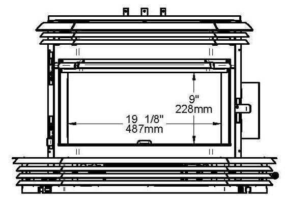
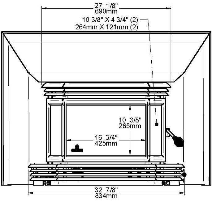
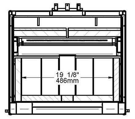
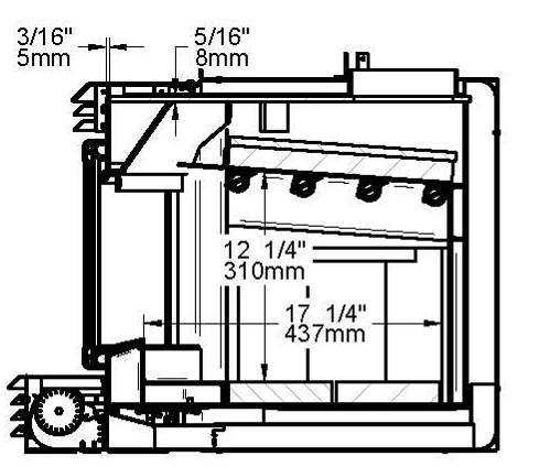
38 8.5 MINIMUM MASONRY OPENING, CLEARANCES TO COMBUSTIBLES, AND FLOOR PROTECTOR 38
39 F CLEARANCES 17" (432 mm) MINIMUM MASONRY OPENING G H I O 10" (254 mm) 14" (356 mm) 22" (559 mm)* 11/2" (38 mm) J K L 22 5/8" (575 mm) 26 1/4" (667 mm)** 17 3/8" (441 mm) FLOOR PROTECTION CANADA USA B 18" (457 mm) Note1 16" (406 mm) Note 1 M 8" (203 mm) N/A (Canada only) N N/A (USA only) 8" (203 mm) Minimum floor to ceiling clearance: 84" (213 cm). * For a 6" (152 mm) to 9 1/2" (241 mm) mantel shelf. See Section 8.3 Compliance of a Combustible Mantel Shelf for other mantel shelf dimensions. ** Where a fresh air intake is needed, we suggest you add a minimum of 4 to the width of the minimum masonry opening. Note 1: From door opening. Note that this model in particular must have 16 inches in front of the blower housing. This distance is already included in the B value of Figures 2.5a and 2.5b. The depth of a non-combustible shelf in front of the insert is included in the calculation of the floor protector s dimensions. IMPORTANT: The masonry hearth should be at least 4 inches (102 mm) higher than the combustible floor in front of it. If the hearth elevation is lower than 4 inches, the noncombustible floor protector in front of the insert should have an R value equal or greater than

40 9 THE VENTING SYSTEM 9.1 GENERAL The venting system, made up of the chimney and the liner inside the chimney, acts as the engine that drives your wood heating system. Even the best insert will not function safely and efficiently as intended if it is not connected to a suitable chimney and liner system. The heat in the flue gases that pass from the insert into the chimney is not waste heat. This heat is what the chimney uses to make the draft that draws in combustion air, keeps smoke inside the insert and safely vents exhaust to outside. You can think of heat in the flue gas as the fuel the chimney uses to make draft. 9.2 BLOCK-OFF PLATE To reduce the possibility of a cold air draft from the masonry chimney to get into the room when the insert in not working, the installation of a sheet metal block-off plate ((A) in the drawing below) is recommended. Once you have made the block-off plate to the proper dimension, cut the pipe hole slightly larger than the liner s diameter and then install the liner through this hole. Set the Block-off plate in place and secure with masonry nails into mortar joints. Finally, seal the joints between the plate and the wall with high temperature silicone, and then use stove-furnace cement to seal between the pipe and the hole. In Canada, CSA B365 Standard permits the use of Roxul type wool stuffed around the liner as it passes through the throat area as an alternative to a sheet metal Block-off plate. However, this method is inferior to the use of a sheet metal block-off plate. 40
41 9.3 SUITABLE CHIMNEYS Your wood insert will provide optimum efficiency and performance when connected to a 6-inch diameter chimney liner. The connection to a chimney having a diameter of at least 5 inches (Canada only) is permitted, if it allows the proper venting of combustion gases and that such application is verified and authorized by a qualified installer. Otherwise, the diameter of the flue should be 6 inches. The reduction of liner diameter to less than 6 should only be done if the total height of the masonry chimney is greater than 20 feet. 9.4 LINER INSTALLATION We recommend the use of a chimney liner (rigid or flexible) to ensure satisfactory performance. To ensure an optimal draft, we also strongly recommend adding a minimum of 12 rigid liner between the top of the masonry chimney and the rain cap. In all cases, liners should be installed in accordance with the liner manufacturer s instructions, including instructions for extension above the masonry. Use Listed Chimney Liners UL 1777, ULC S635. In order to connect the insert to the liner, refer to Section 9.5 Chimney liner installation. ATTENTION INSTALLER: When positioning the unit in a fireplace opening prior to the flue installation, install the insert into the opening until the top lip of air jacket is flush with fireplace facing. If lag-bolts or anchors are to be used to secure the insert, the hole locations should be marked with the unit in place. Remove the insert and locate the anchors. 41
42 9.5 CHIMNEY LINER INSTALLATION The preferred methods for installing the chimney liner are found in Section Use a liner offset adapter (Section 9.5.2) only as a last resort IF THE CHIMNEY LINER DOES ALIGN WITH THE INSERT S FLUE OUTLET, YOU HAVE TWO OPTIONS A) Install the chimney liner starter adapter, provided with the chimney liner. Follow the chimney liner starter adapter manufacturer's instructions. In order to connect the chimney liner starter adapter to the flue outlet, you can install the brackets with the screws that are in the owner s manual kit. Using a powered driver, secure the three brackets with the three screws provided (30131) on top of the insert in the three holes in front of the flue outlet. The long end of the brackets must be attached to the insert. Insert the chimney liner into the flue collar of the unit and secure the liner to the brackets with three self-tapping screws (not included). 42
, which is sold separately.")
43 B) Your dealer may offer a liner fastening system (AC02006), sold separately. Follow the installation instructions provided with the liner fastening system IF THE CHIMNEY LINER DOES NOT ALIGN WITH THE INSERT S FLUE OUTLET You can install a liner offset adapter (AC01370), which is sold separately. Please note that an offset adaptor reduces the free flow of exhaust gases and may result in smoke roll-out from the insert when its door is opened for loading. Only use an offset adaptor if a) there is no other alternative and b) if the total height of the fireplace and chimney is at least 20 feet. If you must install a liner offset adapter, secure the three brackets with the three screws provided (30131) on top of the insert in the three holes in front of the flue outlet. The long end of the brackets must be attached to the insert. The brackets and screws are in the insert s owner s manual kit. Then follow the instructions in the manual provided with the liner offset adapter kit. 43
44 9.6 MINIMUM CHIMNEY HEIGHT The top of the chimney should be tall enough to be above the air turbulence caused when wind blows against the house and its roof. The chimney must extend at least 1 m (3 ft.) above the highest point of contact with the roof, and at least 60 cm (2 ft.) higher than any roof line or obstacle within a horizontal distance of 3 m (10 ft.). 9.7 THE RELATIONSHIP BETWEEN THE CHIMNEY AND THE HOUSE Because the venting system is the engine that drives the wood heating system, it must have the right characteristics. The signs of bad system design are cold backdrafting when there is no fire in the insert, slow kindling of new fires, and smoke roll-out when the door is opened for loading WHY THE CHIMNEY SHOULD PENETRATE THE HIGHEST HEATED SPACE When it is cold outside, the warm air in the house is buoyant so it tends to rise. This tendency of warm air to rise creates a slight pressure difference in the house. Called stack effect, it produces a slightly negative pressure low in the house (relative to outside) and a slightly positive pressure zone high in the house. If there is no fire burning in a heater connected to a chimney that is shorter than the warm space inside the house, the slight negative pressure low in the house will compete against the desired upward flow in the chimney. There are two reasons why the chimney in the house at right will cold backdraft when it is cold outside and there is no fire burning in the insert. First, the chimney runs up the outside of the house, so the air in it is colder and denser than the warm air in the house. And second, the chimney is shorter than the heated space of the house, meaning the negative pressure low in the house will pull outside air down the chimney, through the insert and into the room. Even the finest insert will not work well when connected to this chimney. 44
45 9.8 SUPPLY OF COMBUSTION AIR In Canada, wood inserts are not required to have a supply of combustion air from outdoors because research has shown that these supplies do not give protection against house depressurization and may fail to supply combustion air during windy weather. However, to protect against the risk of smoke spillage due to house depressurization, a carbon monoxide (CO) detector/alarm is required in the room where the insert is installed. The CO detector will provide warning if for any reason the wood insert fails to function correctly AIR SUPPLY IN CONVENTIONAL HOUSES The safest and most reliable supply of combustion air for your wood insert is from the room in which it is installed. Room air is already preheated so it will not chill the fire, and its availability is not affected by wind pressures on the house. Contrary to commonly expressed concerns, almost all tightly-sealed new houses have enough natural leakage to provide the small amount of air needed by the insert. The only case in which the wood insert may not have adequate access to combustion air is if the operation of a powerful exhaust device (such as a kitchen range exhaust) causes the pressure in the house to become negative relative to outdoors. If you do install an air supply through the wall of the house, be aware that its pressure can be affected during windy weather. If you notice changes in wood insert performance in windy weather, and in particular if smoke puffs from the insert, you should disconnect the outdoor air duct from the insert and remove the duct. In some windy conditions, negative pressure at the duct weatherhood outside the house wall may draw hot exhaust gases from the insert backwards through the duct to outdoors. Check the outdoor air duct for soot deposits when the full system is cleaned and inspected at least once each year. 45
46 APPENDIX 1: INSTALLING THE OPTIONAL DOOR OVERLAY In order to complete the assembly of your wood insert, you need to install the door overlay. See figure below for installation instructions: Remove the four screws (A) from the top and the bottom of the door. Install the overlay (B) on the door. Secure with the four screws (A) previously removed. 46
47 APPENDIX 2: AIR CONTROL MECHANISM AND OPTIONAL FACEPLATE INSTALLATION Note: The illustrations may vary from one model to another, but the method of assembly remains the same. Air control mechanism: Fix the air control plate (A) to the air control extension lever (B) using the 1/4" x 1" hex head screws (C) and nuts (D). All parts of this assembly are shipped in the firebox of the insert. Lay the faceplate panels face down on a straight surface. Assemble panels (A), (B) and (C) using four screws #10-24 UNC x ½" (D) and four nuts (E). 47
48 Mount the metal corner gussets components (G) and (H) with screws (F). Set aside. Mount finish trims (I), (J) and (K) using previously pre-mounted metal corner gussets (L) 48
49 Slide the mounted finish trims (M) down the previously mounted faceplate. Secure the finish trim onto the faceplate using U shaped retainers (N) as shown. 49
50 Installation of the faceplate and air control plate on the insert Step 1: Using a Philips screwdriver, remove the screw holding the upper louvers assembly. Step 2: Remove the door from its hinges. 50
51 Step 3: Remove the lower louvers assembly by lifting it up. Step 4: Slide the air control mechanism into the sliding channels below the firebox through the lower right opening of the unit. 51
52 Step 5: Install the mounted faceplate on the unit. Step 6: Put back in place the blower assembly. 52
53 Step 7: Put back the door in place. Step 8: Put back in place the upper louvers assembly and secure it with the previously removed screw. 53
54 Step 9: Secure the faceplate to the unit using four screws #10 x 3/8 provided with the faceplate kit. Make sure the air control mechanism rod moves freely through the lower horizontal slot in the faceplate assembly. Step 10: Install the finish handle onto the air control mechanism rod. 54
55 APPENDIX 3: INSTALLATION OF SECONDARY AIR TUBES AND BAFFLE ITEM DESCRIPTION QUANTITY A BAFFLE EXTENSION 1 B SECONDARY AIR TUBE 4 C 1/8" X 1/2" COTTER PIN 4 D C-CAST BAFFLE BOARD 2 E INSULATION WOOL BLANKET 2 55

56 1. Starting with the rear tube, lean and insert the right end of the secondary air tube into the rear right channel hole. 2. Lift and push the tube into the corresponding opposite nozzle. Align both nozzle and tube locking holes together and secure using a cotter pin with a pair of pliers. 56
 in between the front baffle board (A) and the front secondary air tube (B). 4.")

57 3. Repeat steps 1 and 2 for the two middle tubes. Install the baffle boards and insulation wool blankets (A) and then install the front secondary air tube (B). Finally, install the baffle extension (C) in between the front baffle board (A) and the front secondary air tube (B). 4. To remove the tubes use the above steps in reverse order. Note that secondary air tubes (A) can be replaced without removing the baffle board (B). Important Notes: The air tubes are identified for placement as follows: Model Type of tube 2200 insert Front 67 holes of 0.156" Middle front 67 holes of 0.140" Middle rear 67 holes of 0.140" Rear 67 holes of 0.125" 57
MATRIX Insert (OB02021 model)
") INSTALLATION AND OPERATION MANUAL MATRIX Insert (OB02021 model) US ENVIRONMENTAL PROTECTION AGENCY PHASE II CERTIFIED WOOD INSERT Safety tested according to ULC S628, UL 737 and UL 1482 Standards by an
INSTALLATION AND OPERATION MANUAL MATRIX Insert (OB02021 model) US ENVIRONMENTAL PROTECTION AGENCY PHASE II CERTIFIED WOOD INSERT Safety tested according to ULC S628, UL 737 and UL 1482 Standards by an
INSTALLATION AND OPERATION MANUAL. mfg.com
 2000 Insert INSTALLATION AND OPERATION MANUAL US ENVIRONMENTAL PROTECTION AGENCY PHASE II CERTIFIED WOOD INSERT Safety tested according to ULC S628, UL 737 and UL 1482 Standards by Intertek Testing Services
Installation and Operation Manual Escape 1800 Insert
 Installation and Operation Manual Escape 1800 Insert US ENVIRONMENTAL PROTECTION AGENCY PHASE II CERTIFIED WOOD INSERT Safety tested according to ULC S628, UL 737 and UL 1482 Standards by Intertek Testing
INSTALLATION AND OPERATION MANUAL Solution 2.3 Insert (EB00013 model)
") INSTALLATION AND OPERATION MANUAL Solution 2.3 Insert (EB00013 model) US ENVIRONMENTAL PROTECTION AGENCY PHASE II CERTIFIED WOOD INSERT Safety tested according to ULC S628, UL 737 and UL 1482 Standards
INSTALLATION AND OPERATION MANUAL Solution 2.3 Insert (EB00013 model) US ENVIRONMENTAL PROTECTION AGENCY PHASE II CERTIFIED WOOD INSERT Safety tested according to ULC S628, UL 737 and UL 1482 Standards
Installation and Operation Manual CW29000 Insert (CB00006 model)
") Installation and Operation Manual CW29000 Insert (CB00006 model) US ENVIRONMENTAL PROTECTION AGENCY PHASE II CERTIFIED WOOD INSERT Safety tested according to ULC S628, UL 737 and UL 1482 Standards by an
Installation and Operation Manual CW29000 Insert (CB00006 model) US ENVIRONMENTAL PROTECTION AGENCY PHASE II CERTIFIED WOOD INSERT Safety tested according to ULC S628, UL 737 and UL 1482 Standards by an
INSTALLATION AND OPERATION MANUAL.
 INSTALLATION AND OPERATION MANUAL Stratford US ENVIRONMENTAL PROTECTION AGENCY PHASE II CERTIFIED WOOD FIREPLACE Listed to standards ULC-S610 and UL 127 by an accredited laboratory www.osburn-mfg.com Stove
Everest (OB04015 model)
") INSTALLATION AND OPERATION MANUAL Everest (OB04015 model) CSA B415.1-10 CERTIFIED WOOD FIREPLACE Listed to standard ULC-S610 by an accredited laboratory www.osburn-mfg.com Stove Builder International Inc.
INSTALLATION AND OPERATION MANUAL Everest (OB04015 model) CSA B415.1-10 CERTIFIED WOOD FIREPLACE Listed to standard ULC-S610 by an accredited laboratory www.osburn-mfg.com Stove Builder International Inc.
READ AND KEEP THIS MANUAL FOR REFERENCE
 INSTALLATION AND OPERATION MANUAL Solution 2.5-ZC (EB00016 model) US ENVIRONMENTAL PROTECTION AGENCY PHASE II CERTIFIED WOOD FIREPLACE Listed to standards ULC-S610 and UL 127 www.enerzone-intl.com Stove
READ AND KEEP THIS MANUAL FOR REFERENCE
 INSTALLATION AND OPERATION MANUAL Solution 2.5-ZC (EB00016 model) US ENVIRONMENTAL PROTECTION AGENCY PHASE II CERTIFIED WOOD FIREPLACE Listed to standards ULC-S610 and UL 127 www.enerzone-intl.com Stove
INSTALLATION AND OPERATION MANUAL. mfg.com
 INSTALLATION AND OPERATION MANUAL Stratford US ENVIRONMENTAL PROTECTION AGENCY PHASE II CERTIFIED WOOD FIREPLACE Listed to standards ULC S610 and UL 127 by Intertek Testing Services www.osburn mfg.com
INSTALLATION AND OPERATION MANUAL HE250
 INSTALLATION AND OPERATION MANUAL HE250 US ENVIRONMENTAL PROTECTION AGENCY PHASE II CERTIFIED WOOD FIREPLACE Listed to standards ULC S610 and UL 127 by Intertek Testing Services www.occanada.com Manufactured
HORIZON (OB04010 model)
") INSTALLATION AND OPERATION MANUAL HORIZON (OB04010 model) US ENVIRONMENTAL PROTECTION AGENCY PHASE II CERTIFIED WOOD FIREPLACE Listed to standards ULC-S610 and UL 127 www.osburn-mfg.com Manufactured by:
INSTALLATION AND OPERATION MANUAL HORIZON (OB04010 model) US ENVIRONMENTAL PROTECTION AGENCY PHASE II CERTIFIED WOOD FIREPLACE Listed to standards ULC-S610 and UL 127 www.osburn-mfg.com Manufactured by:
HE250 (VB00002 model)
") INSTALLATION AND OPERATION MANUAL HE250 (VB00002 model) US ENVIRONMENTAL PROTECTION AGENCY PHASE II CERTIFIED WOOD FIREPLACE Listed to standards ULC-S610 and UL 127 www.occanada.com Manufactured by: Stove
INSTALLATION AND OPERATION MANUAL HE250 (VB00002 model) US ENVIRONMENTAL PROTECTION AGENCY PHASE II CERTIFIED WOOD FIREPLACE Listed to standards ULC-S610 and UL 127 www.occanada.com Manufactured by: Stove
Installation and Operation Manual Escape 1800-I Insert (DB03125, DB03127K and DB03128K models)
") Installation and Operation Manual Escape 1800-I Insert (DB03125, DB03127K and DB03128K models) US ENVIRONMENTAL PROTECTION AGENCY PHASE II CERTIFIED WOOD INSERT Safety tested according to ULC S628, UL
Installation and Operation Manual Escape 1800-I Insert (DB03125, DB03127K and DB03128K models) US ENVIRONMENTAL PROTECTION AGENCY PHASE II CERTIFIED WOOD INSERT Safety tested according to ULC S628, UL
INSTALLATION AND OPERATION MANUAL.
 FP15 Waterloo INSTALLATION AND OPERATION MANUAL US ENVIRONMENTAL PROTECTION AGENCY PHASE II CERTIFIED WOOD FIREPLACE Listed to standards ULC-S610 and UL 127 www.valcourtinc.com Manufactured by: Stove Builder
OPERATING & INSTALLATION INSTRUCTIONS FOR ZERO CLEARANCE WOOD INBUILT
 OPERATING & INSTALLATION INSTRUCTIONS FOR ZERO CLEARANCE WOOD INBUILT Stratford CF (OB04006 model) NEW ZEALAND 38 Harris Road, East Tamaki, Auckland Ph: 09 274 8265 Fax 09 274 8472 Email: sales@glendimplex.co.nz
Deco EC00010 Metallic black
 OPERATING & INSTALLATION INSTRUCTIONS FOR ZERO CLEARANCE WOOD INBUILT Deco EC00010 Metallic black Distributed by: My Fireplace Australia Pty Ltd Factory 2 5-7 Hogan Court Pakenham, Victoria 3810, Australia
Solution 1.6 (Model EB00037)
") INSTALLATION AND OPERATION MANUAL Solution 1.6 (Model EB00037) Distributed by: My Fireplace Australia Pty Limited Factory 2, 5-7 Hogan Court, Pakenham, Victoria 3810 Phone number 03 59 415 008 www.myfireplaceaustralia.com.au
INSTALLATION AND OPERATION MANUAL Solution 1.6 (Model EB00037) Distributed by: My Fireplace Australia Pty Limited Factory 2, 5-7 Hogan Court, Pakenham, Victoria 3810 Phone number 03 59 415 008 www.myfireplaceaustralia.com.au
OPERATING & INSTALLATION INSTRUCTIONS FOR INBUILT WOOD HEATERS
 OPERATING & INSTALLATION INSTRUCTIONS FOR INBUILT WOOD HEATERS Premium EC00020 Metallic black Classic EC00021 Metallic black YOUR ECOMAX INBUILT WOOD HEATER HAS BEEN TESTED WITH OUR ORIGINAL ECOMAXX INBUILT
Please keep this document!
 Installation and operating instructions for the HEATMAX WOOD FURNACE DF01000 Verified and tested for Canada and the United States by : Stove Builder International Inc. 250, rue de Copenhague, St-Augustin-de-Desmaures
OPERATING & INSTALLATION INSTRUCTIONS FOR PEDESTAL WOOD HEATERS
 OPERATING & INSTALLATION INSTRUCTIONS FOR PEDESTAL WOOD HEATERS Premium EC00001 Metallic black EC00002 Metallic charcoal Classic EC00003 Metallic charcoal EC00004 Metallic black Distributed by: My Fireplace
INSTALLATION AND OPERATION MANUAL HE200
 INSTALLATION AND OPERATION MANUAL HE200 US ENVIRONMENTAL PROTECTION AGENCY PHASE II CERTIFIED WOOD FIREPLACE Listed to standards ULC S610 and UL 127 by Intertek Testing Services www.occanada.com Manufactured
OSBURN 2000 (OB02005 Model)
") INSTALLATION AND OPERATION MANUAL OSBURN 2000 (OB02005 Model) Distributed by Glen Dimplex Australasia NEW ZEALAND 38 Harris Road, East Tamaki, Auckland Ph: 09 274 8265 Fax 09 274 8472 Email: sales@glendimplex.co.nz
INSTALLATION AND OPERATION MANUAL OSBURN 2000 (OB02005 Model) Distributed by Glen Dimplex Australasia NEW ZEALAND 38 Harris Road, East Tamaki, Auckland Ph: 09 274 8265 Fax 09 274 8472 Email: sales@glendimplex.co.nz
SOHO (OB01522 Model) INSTALLATION AND OPERATION MANUAL. Distributed by Glen Dimplex Australasia READ AND KEEP THIS MANUAL FOR REFERENCE
 INSTALLATION AND OPERATION MANUAL. Distributed by Glen Dimplex Australasia READ AND KEEP THIS MANUAL FOR REFERENCE") INSTALLATION AND OPERATION MANUAL SOHO (OB01522 Model) NEW ZEALAND 38 Harris Road, East Tamaki, Auckland Ph: 09 274 8265 Fax 09 274 8472 Email: sales@glendimplex.co.nz www.glendimplex.com.au Distributed
INSTALLATION AND OPERATION MANUAL SOHO (OB01522 Model) NEW ZEALAND 38 Harris Road, East Tamaki, Auckland Ph: 09 274 8265 Fax 09 274 8472 Email: sales@glendimplex.co.nz www.glendimplex.com.au Distributed
Installation and Operation Manual.
 FP12 Mundo (FP12CE) Installation and Operation Manual Installation Instructions This installation manual will help you obtain a safe, efficient, dependable installation for your fireplace and chimney system.
HEATMAX II WOOD FURNACE (DF01001 model)
") Installation and operating instructions for the HEATMAX II WOOD FURNACE (DF01001 model) Verified and tested for Canada and the United States by an accredited laboratory Stove Builder International Inc.
Installation and operating instructions for the HEATMAX II WOOD FURNACE (DF01001 model) Verified and tested for Canada and the United States by an accredited laboratory Stove Builder International Inc.
TUNDRA WOOD FURNACE (DF02005 model)
") Installation and operating instructions for the TUNDRA WOOD FURNACE (DF02005 model) www.kfenergy.cz výrobce: Stove Builder International Inc. 250, rue de Copenhague, St-Augustin-de-Desmaures (Quebec) Kanada
Installation and operating instructions for the TUNDRA WOOD FURNACE (DF02005 model) www.kfenergy.cz výrobce: Stove Builder International Inc. 250, rue de Copenhague, St-Augustin-de-Desmaures (Quebec) Kanada
Before selecting your wood heater, it is very important that you clearly identify what your needs are:
 How to choose the best wood wood heater? Before selecting your wood heater, it is very important that you clearly identify what your needs are: What are the dimensions of your house (W x D x H)? How many
Installation And Operation Manual.
 FP7CE Antoinette Installation And Operation Manual Installation Instructions This installation manual will help you obtain a safe, efficient, dependable installation for your fireplace and chimney system.
Please keep this document!
 Installation and operating instructions for the HEATPACK WOOD FURNACE (DF00500 model) Verified and tested for Canada and the United States by an accredited laboratory Stove Builder International Inc. 250,
INTRODUCTION TO HITZER STOVES INSTALLATION AND OPERATION
 INTRODUCTION TO HITZER STOVES INSTALLATION AND OPERATION Welcome to our proud team of HITZER heater owners. Your HITZER heater has the finest in Swiss craftsmanship and quality material to assure you that
FIREPLACE INSERT, MODEL VOLCANO PLUS OWNER S MANUAL - INSTALLATION - OPERATION. Save These Instructions for Future Reference.
 FIREPLACE INSERT, MODEL VOLCANO PLUS Tested and certified to: by Intertek ULC S628-M93 UL 1482-1996 OWNER S MANUAL - INSTALLATION - OPERATION Save These Instructions for Future Reference. Manufactured
Troubleshooting and Maintenance: Wood Stoves
 Troubleshooting and Maintenance: Wood Stoves What product should I use to clean the glass? There exist many specialized products on the market. The majority works very well. They are usually sold at both
qüé=`üáãåéó An effective chimney is an important part of any successful wood-burning system.
 8. qüé=`üáãåéó An effective chimney is an important part of any successful wood-burning system. How Chimneys Work An effective chimney is an important part of any successful wood-burning system. Many of
Before selecting your stove, it is very important that you clearly identify what your needs are:
 How to choose the best wood stove? Before selecting your stove, it is very important that you clearly identify what your needs are: What are the dimensions of your house (W x D x H)? How many floors does
tççç= ÜÉ~íáåÖ çéíáçåë
 3. tççç= ÜÉ~íáåÖ çéíáçåë There are several different types of wood-heating appliances to choose from. Each type is intended for a particular use, and each has its own set of advantages and disadvantages.
OWNER`S MANUAL 2400 MODEL INSERT
 OWNER`S MANUAL 2400 MODEL INSERT US ENVIRONMENTAL PROTECTION AGENCY PHASE II CERTIFIED WOOD INSERT Verified and tested following ULC S627 and UL 1482 Standards by: Manufactured by : STOVE BUILDER INTERNATIONAL
HOMEOWNERS GUIDE FOR YOUR WOOD BURNING FIREPLACE
 P127003 01 P/N 127003-01 Rev. B 01/2016. HOMEOWNERS GUIDE FOR YOUR WOOD BURNING FIREPLACE Read this manual carefully before using your wood burning fireplace. Understand and observe all guidelines included
HOMEOWNERS GUIDE FOR YOUR WOOD BURNING FIREPLACE
 P127004 01 P/N 127004-01 Rev. B 01/2016. HOMEOWNERS GUIDE FOR YOUR WOOD BURNING FIREPLACE Read this manual carefully before using your wood burning fireplace. Understand and observe all guidelines included
Malm Fireplaces, Inc. 368 Yolanda Avenue, Santa Rosa, CA (707) Fax: (707)
 Fax: (707)") Malm Fireplaces, Inc. 368 Yolanda Avenue, Santa Rosa, CA 95404 (707) 523-7747 - Fax: (707) 571-8036 info@malmfireplaces.com Fire Drum 2 Tested to U/L Standards 1482 and 737 Assembly And Installation Instructions
Malm Fireplaces, Inc. 368 Yolanda Avenue, Santa Rosa, CA 95404 (707) 523-7747 - Fax: (707) 571-8036 info@malmfireplaces.com Fire Drum 2 Tested to U/L Standards 1482 and 737 Assembly And Installation Instructions
Dovre 700CBW Cast Iron Wood Stove INSTALLATION INSTRUCTIONS 700G/1095
 Dovre 700CBW Cast Iron Wood Stove INSTALLATION INSTRUCTIONS 700G/1095 Before commencing with the installation it is important that these instructions are read and fully understood. The DOVRE 700CBW is
H530. Installation and user manual. - Please read this manual carefully and save the instructions - Version: 10/09. Tested and Listed by:
 Tested and Listed by: C US Portland Oregon USA OMNI-Test Laboratories, Inc. - Please read this manual carefully and save the instructions - Installation and user manual H530 Version: 10/09 TABLE OF CONTENTS
OWNER`S MANUAL 2200 MODEL INSERT
 OWNER`S MANUAL 2200 MODEL INSERT US ENVIRONMENTAL PROTECTION AGENCY PHASE II CERTIFIED WOOD INSERT Verified and tested following ULC S627 and UL 1482 Standards by: Manufactured by : STOVE BUILDER INTERNATIONAL
OWNER`S MANUAL. Escape 1400-I Insert
 OWNER`S MANUAL Escape 1400-I Insert US ENVIRONMENTAL PROTECTION AGENCY PHASE II CERTIFIED WOOD INSERT Verified and tested following ULC S68 and UL 148 Standards by: Manufactured by : STOVE BUILDER INTERNATIONAL
Pellet Vent INSTALLATION INSTRUCTIONS
 Pellet Vent INSTALLATION INSTRUCTIONS A MAJOR CAUSE OF CHIMNEY RELATED FIRES IS FAILURE TO MAINTAIN REQUIRED CLEARANCES (AIR SPACES) TO COMBUSTIBLE MATERIALS. IT IS OF THE UTMOST IMPORTANCE THAT THIS PELLET
OWNER`S MANUAL. XTD1.5-I & XTD1.9-I Inserts
 OWNER`S MANUAL XTD1.5-I & XTD1.9-I Inserts US ENVIRONMENTAL PROTECTION AGENCY PHASE II CERTIFIED WOOD INSERTS Verified and tested following ULC S68 and UL 148 Standards by: Manufactured by : STOVE BUILDER
OWNER`S MANUAL. Escape 1400-I Inserts
 OWNER`S MANUAL Escape 1400-I Inserts US ENVIRONMENTAL PROTECTION AGENCY PHASE II CERTIFIED WOOD INSERT Verified and tested following ULC S628 and UL 1482 Standards by: Manufactured by : STOVE BUILDER INTERNATIONAL
HOMEOWNER'S GUIDE FOR YOUR CONTEMPO FIREPLACE TABLE OF CONTENTS
 10031 Southern SE Albuquerque NM 87123 505.291.0500 fax 505.291.9317 HOMEOWNER'S GUIDE FOR YOUR CONTEMPO FIREPLACE Before building your first fire, read this warranty and operation manual carefully. By
Installation And Operation Manual.
 FP1LM Manoir Installation And Operation Manual Qualified Clean Burning Decorative Fireplace U.S. EPA Low Mass Wood-burning Fireplace voluntary program phase 2 emission level qualified model Safety tested
ULC-S610-M87 (A1998), UL
, UL") Gyrofocus Design Installation & Operating Manual v.6.1 EN Tested by OMNI-Test Laboratories, Inc. and approved to ULC-S610-M87 (A1998), UL 737-1996 And ULC S627-00 US EPA exempt this document was packed
Gyrofocus Design Installation & Operating Manual v.6.1 EN Tested by OMNI-Test Laboratories, Inc. and approved to ULC-S610-M87 (A1998), UL 737-1996 And ULC S627-00 US EPA exempt this document was packed
OWNER`S MANUAL. Escape 1400-I Insert
 OWNER`S MANUAL Escape 1400-I Insert US ENVIRONMENTAL PROTECTION AGENCY PHASE II CERTIFIED WOOD INSERT Verified and tested following ULC S68 and UL 148 Standards by: Manufactured by : STOVE BUILDER INTERNATIONAL
Fisher Hanmer INSTALLATION & OPERATION INSTRUCTIONS FREESTANDING WOOD FIRE. January
 Fisher Hanmer FREESTANDING WOOD FIRE INSTALLATION & OPERATION INSTRUCTIONS January 2015 www.fisherstoves.co.nz Congratulations on the purchase of your Fisher wood fire. Please read this installation and
NOT INSTALL THIS UNIT IN A MOBILE HOME.
 PIN-A-F -A-FIRE SPIN PIN ASSEMBLY AND INSTALLATION INSTRUCTIONS Listed by Warnock Hersey Tested to U/L Standard 737 & 1482 SAFETY NOTICE If this fireplace is not properly installed, a house fire may result.
Manufactured for: HearthStone Quality Home Heating Products, Inc. 317 Stafford Avenue, Morrisville VT 05661
 WFP-75 (Model 8410) Woodstove OWNER'S MANUAL Installation And Operating Instructions Manufactured for: HearthStone Quality Home Heating Products, Inc. 317 Stafford Avenue, Morrisville VT 05661 PLEASE READ
SCOTTY WOOD FURNACE Model DB-102 OWNER S MANUAL IMPORTANT
 SCOTTY WOOD FURNACE Model DB-102 OWNER S MANUAL IMPORTANT READ OWNER S MANUAL THOROUGHLY BEFORE INSTALLING FURNACE OR LIGHTING FIRE. CONSULT LOCAL AUTHORITIES IF IN DOUBT ABOUT YOUR LOCAL FIRE SAFETY REGULATIONS.
NOVA OWNER S MANUAL. Revision #0001 Report #1801V2
 NOVA OWNER S MANUAL Safety Notice: Please save these instructions for future reference. Please read this entire manual before you install and use your new room heater. Failure to follow instructions may
Can I install my stove using an existing masonry chimney?
 FAQ: Wood Stoves Can I install a wood stove in my mobile home? Yes, you can install a wood stove in a mobile home. However, the stove you install must have been specifically approved for mobile home applications.
INSTALLATION & OPERATION INSTRUCTIONS
 Fisher CHARLESTON Fisher DENNISTON MULTI-FUEL HEATER INSTALLATION & OPERATION INSTRUCTIONS January 2015 www.fisherstoves.co.nz Congratulations on the purchase of your Fisher multi-fuel heater. Please read
WOOD STOVE SERVICE MANUAL
 WOOD STOVE SERVICE MANUAL WARNING Fire Risk. Hearth & Home Technologies disclaims any responsibility for, and the warranty will be voided by, the following actions: Installation and use of any damaged
PLEASE RETAIN THIS MANUAL FOR FUTURE REFERENCE. Listed to standards ULC-S610 and UL-127. Manufactured by: Stove Builder International Inc.
 MODEL FP 10 Lafayette Installation Instructions This installation manual will help you obtain a safe, efficient, dependable installation for your fireplace and chimney system. Please read and understand
HOMEOWNERS GUIDE FOR YOUR WOOD BURNING FIREPLACE
 P127003 01 P/N 127003-01 Rev. C 02/2018 HOMEOWNERS GUIDE FOR YOUR WOOD BURNING FIREPLACE Read this manual carefully before using your wood burning fireplace. Understand and observe all guidelines included
March 9th, 2009 Reviewed MYSTERE wood burning stove 490, rue de l'argon Québec (Québec) G2N 2C9 Phone: Fax :
 G2N 2C9 Phone: Fax :") March 9th, 2009 Reviewed MYSTERE wood burning stove 490, rue de l'argon Québec (Québec) G2N 2C9 Phone: 418-849-8095 Fax : 418-849-0077 www.jaroby.com CAN/ULC S627-M00 1 CONTENTS WARNING... 4 NOTICE...
March 9th, 2009 Reviewed MYSTERE wood burning stove 490, rue de l'argon Québec (Québec) G2N 2C9 Phone: 418-849-8095 Fax : 418-849-0077 www.jaroby.com CAN/ULC S627-M00 1 CONTENTS WARNING... 4 NOTICE...
Warmth, from the heart of J.A. Roby
 Warmth, from the heart of J.A. Roby Conforms to UL Std. 1482 Certified to ULC Std. S627 July 13th, 2012 Reviewed ATMOSPHERE BMR EPA 490, rue de l'argon Québec (Québec) G2N 2C9 Phone: 418-849-8095 Fax :
Operating Manual USA & Canada.
 Operating Manual USA & Canada www.tulikivi.com Welcome to the world of Tulikivi Congratulations on your excellent choice of product. We wish you many warm moments around your Tulikivi fireplace. By following
Nectre Inbuilt LE. Operating Instructions. Efficient Warm Friendly. Keep instructions in a safe place for future reference.
 Nectre Inbuilt LE Operating Instructions Efficient Warm Friendly Keep instructions in a safe place for future reference Do not throw away Pecan Engineering Pty Ltd proudly supports the activities of Landcare
ATMOSPHERE WOOD STOVE. Conforms to UL Std Certified to ULC Std. S627. June 1 st, 2013 Reviewed ATMOSPHERE
 ATMOSPHERE WOOD STOVE Conforms to UL Std. 1482 Certified to ULC Std. S627 June 1 st, 2013 Reviewed ATMOSPHERE 490, rue de l'argon Quebec, Qc CANADA G2N 2C9 Phone: 418-849-8095 Fax : 418-849-0077 www.jaroby.com
OWNERS MANUAL MODEL DO110 & DO180 IS CERTIFIED TO: Unit Serial # Purchased From Company Address
 OWNERS MANUAL MODEL DO110 & DO180 IS CERTIFIED TO: UL 391 CAN/CSA B366.1 Unit Serial # Purchased From Company Address Name of Installer Installer Telephone # Date Installed IMPORTANT This manual must be
ULC-S610-M87 (A1998), UL
, UL") Ergofocus Design Installation & Operating Manual v.12 EN Tested by OMNI-Test Laboratories, Inc. and approved to ULC-S610-M87 (A1998), UL 737-2011 And ULC S627-00 Report Number: 304-F-04-2 US EPA exempt
Ergofocus Design Installation & Operating Manual v.12 EN Tested by OMNI-Test Laboratories, Inc. and approved to ULC-S610-M87 (A1998), UL 737-2011 And ULC S627-00 Report Number: 304-F-04-2 US EPA exempt
Nectre N60. Operating Instructions. Efficient Warm Friendly. Keep instructions in a safe place for future reference.
 Nectre N60 Operating Instructions Efficient Warm Friendly Keep instructions in a safe place for future reference Do not throw away Pecan Engineering Pty Ltd proudly supports the activities of Landcare
SOLID FUEL HEATER JAYLINE CLASSIC CA FS 2006 INSTALLATION & OPERATION INSTRUCTIONS FEBRUARY 2007
 1 SOLID FUEL HEATER JAYLINE CLASSIC CA FS 2006 INSTALLATION & OPERATION INSTRUCTIONS FEBRUARY 2007 We thank you for choosing Jayline and welcome you among the many happy Jayline customers. Please keep
JAYLINE CA FREESTANDING WOOD FIRE
 JAYLINE CA FREESTANDING WOOD FIRE INSTALLATION & OPERATION INSTRUCTIONS Please leave this information with the appliance PRODUCT REGISTRATION TO ACTIVATE YOUR 15 YEAR GUARANTEE, PLEASE COMPLETE AND RETURN
Corn Flame Energy Corn Stove Model 3000
 Corn Flame Energy Corn Stove Model 3000 Installation and Operation Guide Read thoroughly before starting installation Save this manual for future reference SAFETY NOTICE If this stove is not properly installed,
Emifocus. Design Installation & Operating Manual v.2 FR Tested by OMNI-Test Laboratories, Inc. and approved to UL and ULC-S627-00
 Emifocus Design Installation & Operating Manual v.2 FR Tested by OMNI-Test Laboratories, Inc. and approved to UL 737-2011 and ULC-S627-00 Report Number : 304-F-08-2 US EPA exempt this document was packed
INSTALLATION AND OPERATING GUIDE. PACIFIC INSERT Design - D SAFETY NOTICE. Model PLEASE SAVE THESE INSTRUCTIONS
 PLEASE SAVE THESE INSTRUCTIONS SAFETY NOTICE If this stove is not properly installed, a house fire may result. For your safety, follow the installation directions. Consult local building or fire officials
HYBRID-FYRE FLUSH WOOD INSERTS
 HYBRID-FYRE FLUSH WOOD INSERTS CLEANEST BURNING WOOD INSERTS IN THE WORLD Large Flush Wood Hybrid-Fyre Insert The Avalon Large Flush Wood Hybrid-Fyre Insert is one of the cleanest and most efficient wood
Nectre MK2 LE. Operating Instructions. Efficient Warm Friendly. Keep instructions in a safe place for future reference.
 Nectre MK2 LE Operating Instructions Efficient Warm Friendly Keep instructions in a safe place for future reference Do not throw away Pecan Engineering Pty Ltd proudly supports the activities of Landcare
WOOD STOVE OWNERS AND OPERATORS MANUAL MODELS 1000, 1600, 1600INS, 2100 EF-183
 WOOD STOVE MODELS 1000, 1600, 1600INS, 2100 OWNERS AND OPERATORS MANUAL EF-183 TABLE OF CONTENTS PLEASE READ AND SAVE INSTRUCTIONS SAFETY WARNING 2 OPERATING INSTRUCTIONS 3 PEDESTAL INSTALLATION 7 BRICK
RS Chimney Fan for Solid Fuel Applications
 Installation & Operating Manual RS Chimney Fan for Solid Fuel Applications USA CAN Product Information... Chapter 1 + 2 Mechanical Installation... Chapter 3 Electrical Installation... Chapter 4 Start Up
Cabello Models: 1200-C & 1700-C Insert
 SHERWOOD INDUSTRIES IS AN ENVIRONMENTALLY RESPONSIBLE COMPANY. THIS MANUAL IS PRINTED ON RECYCLED PAPER. PLEASE SAVE THESE INSTRUCTIONS FOR FUTURE REFERENCE Cabello Models: 1200-C & 1700-C Insert OWNERS
Troubleshooting Guide
 Troubleshooting Guide CONTENTS 1: Door Glass Blackening...Troubleshooting 1, page 3 This Troubleshooting guide is supplementary to, and must be used in conjunction with, the Instructions for Use, Installation
Boston OWNERS MANUAL. Model: 1200-C & 1700C Free Standing WARRANTY REGISTRATION
 WARRANTY REGISTRATION IS QUICK AND EASY ONLINE: enviro.com Boston Model: 1200-C & 1700C Free Standing OWNERS MANUAL SHERWOOD INDUSTRIES IS AN ENVIRONMENTALLY RESPONSIBLE COMPANY. THIS MANUAL IS PRINTED
PLEASE KEEP THESE INSTRUCTIONS FOR FUTURE REFERENCE PELLET STOVE HP-0020S
 PLEASE KEEP THESE INSTRUCTIONS FOR FUTURE REFERENCE PELLET STOVE HP-0020S Freestanding OWNER S MANUAL Contact your building or fire officials about restrictions and installation inspection requirements
Cast Iron Fireplace Insert
 Installation and Operation Instructions for USA only Model: HF-577IU7 Cast Iron Fireplace Insert (EPA Approved Wood Burning) Report # 375-S-07-2 Conform to UL 1482-2010 KINDLY SAVE THESE INSTRUCTIONS FOR
Cabello 1200 FPI & Cabello 1700 FPI W O O D S T O V E I N S E R T OWNER`S MANUAL
 Cabello 1200 FPI & Cabello 1700 FPI WARRANTY REGISTRATION enviro.com/warranty W O O D S T O V E I N S E R T OWNER`S MANUAL PLEASE READ THIS ENTIRE MANUAL BEFORE INSTALLATION AND USE OF THIS WOOD BURNING
JADE RANGE LOG BROILER MODELS: JLB SERIES
 Jade Range LLC, A Middleby Company 2650 Orbiter Ave. Brea, CA 92821 Telephone (714) 961-2400 FAX (714) 961-2550 JADE RANGE LOG BROILER MODELS: JLB SERIES INSTALLATION, OPERATION AND MAINTENANCE INSTRUCTIONS
RS Chimney Fan for Solid Fuel Applications
 Installation & Operating Manual RS Chimney Fan for Solid Fuel Applications USA CAN Product Information... Chapters 1 + 2 Mechanical Installation... Chapter 3 Electrical Installation... Chapter 4 Start
Pacific Wood Insert MODEL PACIFIC WOOD INSERT DESIGN-D INSTALLATION AND OPERATING INSTRUCTIONS SAFETY NOTICE
 IMPORTANT: THESE INSTRUCTIONS ARE TO REMAIN WITH THE HOMEOWNER Pacific Wood Insert SAFETY NOTICE If this stove is not properly installed, a house fire may result. For your safety, follow the installation
SHERWOOD INDUSTRIES IS AN ENVIRONMENTALLY RESPONSIBLE COMPANY. THIS MANUAL IS PRINTED ON RECYCLED PAPER.
 SHERWOOD INDUSTRIES IS AN ENVIRONMENTALLY RESPONSIBLE COMPANY. THIS MANUAL IS PRINTED ON RECYCLED PAPER. PLEASE KEEP THESE INSTRUCTIONS FOR FUTURE REFERENCE PELLET STOVE Milan Fireplace Insert OWNER S
SHERWOOD INDUSTRIES IS AN ENVIRONMENTALLY RESPONSIBLE COMPANY. THIS MANUAL IS PRINTED ON RECYCLED PAPER.
 SHERWOOD INDUSTRIES IS AN ENVIRONMENTALLY RESPONSIBLE COMPANY. THIS MANUAL IS PRINTED ON RECYCLED PAPER. PLEASE KEEP THESE INSTRUCTIONS FOR FUTURE REFERENCE PELLET STOVE WINDSOR OWNER S MANUAL Contact
Before selecting your stove, it is very important that you clearly identify what your needs are:
 How to choose the best stove? Before selecting your stove, it is very important that you clearly identify what your needs are: What are the dimensions of your house (W x D x H)? How many floors does the
104 MK II WOOD-BURNING STOVE
 104 MK II WOOD-BURNING STOVE SAFETY NOTICE PLEASE READ THIS ENTIRE MANUAL BEFORE YOU INSTALL AND USE YOUR NEW ROOM HEATER. FAILURE TO FOLLOW INSTRUCTIONS MAY RESULT IN PROPERTY DAMAGE, BODILY INJURY OR
TABLE OF CONTENTS. Site preparation 2 Placement. 2 Chimney and stove pipe connections. 2
 TABLE OF CONTENTS SECTION TITLE PAGE 1. SITE PREPARATION AND INSTALLATION Site preparation 2 Placement. 2 Chimney and stove pipe connections. 2 Installation. 3 Water supply and return.. 3 Pressure/relief
CHALET 1600I WOOD Fireplace Insert
 Shown with optional nickel door (10-0203) and brushed nickel fan inlay (40-1103) CHALET 1600I WOOD Fireplace Insert Users Installation Operation and Maintenance Manual PRIOR TO FIRST FIRE: Remove all labels
Installation and Operation Manual
 Installation and Operation Manual FP-7-LM ANTOINETTE Qualified Clean Burning Decorative Fireplace U.S. EPA Low Mass Wood-burning Fireplace voluntary program phase 2 emission level qualified model Safety
Kodiak 1200 FS & Kodiak 1700 FS F R E E S T A N D I N G W O O D S T O V E OWNER S MANUAL
 Kodiak 1200 FS & Kodiak 1700 FS WARRANTY REGISTRATION enviro.com/warranty F R E E S T A N D I N G W O O D S T O V E OWNER S MANUAL PLEASE READ THIS ENTIRE MANUAL BEFORE INSTALLATION AND USE OF THIS WOOD
Installation & Operation Manual
 Installation & Operation Manual 100 Neilson Street, Onehunga, Auckland, New Zealand Tel: 09 634 1483 Fax: 09 634 6804 www.crighton.co.nz PRE-ASSEMBLY Having removed the outer packaging from your stove,
Owner s Manual MODELS: VG150
 Owner s Manual MODELS: VG150 CAUTION: Please read this entire manual before you install or use your new room heater. Failure to follow instructions may result in property damage, bodily injury, or even
napoleonfireplaces.com WOOD BURNING WOOD BURNING FIREPLACES
 napoleonfireplaces.com WOOD BURNING WOOD BURNING FIREPLACES Add an element of home to your house with a Napoleon wood burning fireplace. NZ6000 High Country...4-5 NZ3000 High Country...6-7 NZ-26 Prestige...8-9
Specialists in fireplace design and manufacture CUBE DOUBLE SIDED INSTALLATION & OPERATING INSTRUCTIONS IMPORTANT:
 Specialists in fireplace design and manufacture CUBE DOUBLE SIDED INSTALLATION & OPERATING INSTRUCTIONS IMPORTANT: INSTALLER, PLEASE LEAVE THESE INSTRUCTIONS WITH THE UNIT ON COMPLETION. 10 YEAR FIREBOX
Summit Wood Insert MODEL SUMMIT WOOD INSERT DESIGN-A INSTALLATION AND OPERATING INSTRUCTIONS SAFETY NOTICE
 IMPORTANT: THESE INSTRUCTIONS ARE TO REMAIN WITH THE HOMEOWNER Summit Wood Insert SAFETY NOTICE If this stove is not properly installed, a house fire may result. For your safety, folow the installation