13-1. Temperature Regulator
|
|
|
- Alexandra Goodman
- 5 years ago
- Views:
Transcription
1 -1
2 Step 0 Type/Structure/Features Please refer to this for type, structure and features of. Step 1 Selection Please look at the ID chart to choose the right products depending on the intended uses. Details are on the product page. Step 2 Sizing Please check the required Cv value from size selection data on P.-7, or size selection chart on the product page of each products. Step 3 Attention for usage -2
3 What is? A temperature regulator, that is self-acting, automatically controls the steam/liquid flow, in response to the temperature changes in the cooled/heated media, and keeps the cooled/heated fluid temperature at a constant level. Automatic temperature regulator requires no electricity for operation, so it keeps on operating in case of electricity failure. No need for electric construction and temperature can be adjusted just by twisting the handle. Selection of Heating Direct acting type Use steam or hot water in order to raise the temperature of heat exchanger and storage tank. Controls heating media in order to maintain set temperature. Pilot type Use steam or hot water in order to raise the temperature of heat exchanger and storage tank. It has larger flow capacity than direct acting type. Cooling Controls cooling media in order to maintain set temperature. Direct acting type Use cold water or cooling media in order to cool down the temperature of liquid such as lubricant oil. Internal pressure bellows Recommended to be used at a place where the difference between the set temperature and the ambient temperature is 30 C or more. Bellows External pressure bellows Insusceptible to the ambient temperature and usable even at a place where the difference between the set temperature and the ambient temperature is 30 C or less. For liquid For air -3


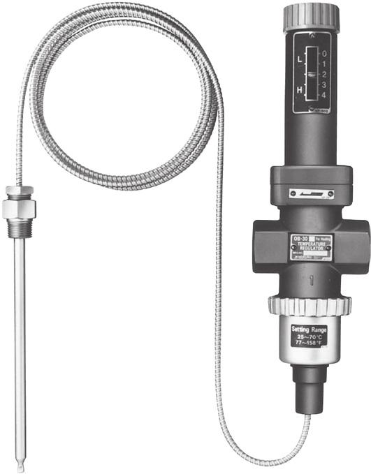
4 Features of Direct Acting Type <OB-30> Application For small heat exchanger, HVAC and plating apparatus. Thermal bulb Red or Blue handle Red for heating and blue for cooling. Easily adjust the temperature by handle without any tool. Dial For checking the set temperature. Thermal bulb can be installed in any position because the temperature is sensed by sealing gas which will not be mixed with fluid in case of breakage. It is especially recommended to the food processing industry. All sizes of both heating and cooling type use same thermal bulb. It is available with stainless steel (SUS304) made thermal well as an option. Pressure balancing mechanism Equipped with two bellows called balance bellows which ensure stable temperature regulation, the OB-30 is not affected by inlet pressure fluctuation. Light and compact Enables easy piping construction. High durability and sealing function Stainless steel and PTFE materials are used for the valve disc, which ensures high durability and sealing function. 2 m is the standard of capillary tube. 3 m and 5 m is also available. OB-30 OB-30U -4
5 TEMPERATURE REGULATORS Control ID-Charts ID-Charts Model Type Fluid Material Max. Press. (MPa) Max. Temp. ( C) Connection Size Feature Page Steam 1.0 OB-30 JIS Rc 15-25A -11 OB-30U External pressure bellows Hot water 1.7 CAC406 Steam 1.0 Hot water C JIS Rc (union joint) Heating (red handle) Low-leakage designed single seat valve 15-25A -11 OB-31 JIS Rc 15-25A -11 External pressure bellows Cold water, Refrigerant CAC C Cooling (blue handle) Low-leakage designed single seat valve OB-31U JIS Rc (union joint) 15-25A -11 OB-2000 External pressure bellows Steam FCD or C JIS Rc 15-50A Heating JIS 10KFF JIS 20KRF A Pilot type Large flow capacity -14 OB-1 OB-1G OB-2 OB-2G Internal pressure bellows External pressure bellows Internal pressure bellows External pressure bellows Steam, Hot water Steam, Hot water CAC C * Max. pressure depends on size. For details please refer to P.-20. JIS Rc (union joint) FC * 180 C JIS 10KFF 15-40A Heating A Low temperature heating A Heating A Low temperature heating -20-5
6 Model Type Fluid Material Max. Press. (MPa) Max. Temp. ( C) Connection Size Feature Page OB-3 Internal pressure bellows 15-40A Cooling -23 Cold water, Refrigerant CAC C JIS Rc (union joint) OB-3G External pressure bellows 15-40A Low temperature cooling -23 OB-4 Internal pressure bellows A Cooling -26 Cold water, Refrigerant FC * 180 C JIS 10KFF OB-4G External pressure bellows A Low temperature cooling -26 OB-5 Internal pressure bellows CAC C JIS Rc (union joint) 15-25A Low-leakage designed single seat valve -29 Steam, Hot water OB-6 Internal pressure bellows FC C JIS 10KFF 15-25A Low-leakage designed single seat valve -31 * Max. pressure depends on size. For details please refer to P
7 Nominal Size Selection for Calculation formula for Cv value (1) For steam When P2 > When P2 (2) For liquid Cv = P1 2 P1 2 Wk Cv = 8 P(P1 + P2) Cv = Wk 120P V G P W: Max. flow rate of steam [kg/h] P 1 : Inlet pressure [MPa A] P 2 : Outlet pressure [MPa A] ΔP: P 1 P 2 [MPa] k : x {superheated steam temperature [ C] saturated steam temperature [ C]} G : Specific gravity (against water in the case of fluid) V : Max. flow rate of fluid [m 3 /h] Cv: Cv value of each nominal size Cv value table Model Nominal size OB-30, 31 OB-2000 OB-1, 1G OB-2, 2G OB-3, 3G OB-4, 4G OB-5 OB-6 Point to remember when selecting the size If system has small capacity and seat leakage become a problem, select single valve type such as OB-30 Series, OB-5 or OB-6. Differential pressure between inlet and outlet of temperature regulator should be 0.05 MPa in principle. It is recommended that inlet pressure be MPa to obtain the best performance of the temperature regulator and its longer product life. Formula for calculating necessary steam volume <Calculation formula> The quantity of steam required to increase the temperature of Q kg of water by B C in time A (h) is: W = B x Q 500 x A Select a nominal size by applying the calculated quantity of steam W and the steam pressure P to the flow rate chart for nominal size selection. <Calculation example> When increasing the temperature of 7000 kg of water from 20 C to 60 C in an hour with 0.5 MPa steam (60 20) x 7000 W = = 560 (kg/h) 500 x 1 Set the safety factor at 80 to 90%. W: Quantity of steam B: Temperature (difference of temperature) Q: Water (kg) A: Time (hr) -7
8 Guidelines for OB-30 Series OB-30 Series Precautions during Installation Installation of body 1. Be sure not to lose the bellows follower (attached component). 2. Install the temperature regulator perpendicularly to horizontal piping with the handle facing upward. 3. Check the direction of the temperature regulator so that the fluid flowing and the arrow marked on the body are in the same direction. 4. Be sure to install pressure gauge, strainer and bypass line to the piping (see "Piping Example" below). 5. The pressure of heating fluid should be reduced with a pressure reducing valve if it exceeds the maximum pressure. 6. Completely discharge the fluid inside the piping and close the stop valves installed at before and after the temperature regulator before stopping operation of the product for an extended period. 7. Be sure to remove foreign matter from the piping through the bypass line at the starting before operating the temperature regulator. Assembly of body and thermal bulb Install the bellows follower into the bellows at thermal bulb with its flat surface facing downward and then screw it into the lower surface of the body by the ring. During the assembly, it makes assembly easy to loosen the handle to direction of the "Low" position. Body Bellows follower Ring Installation of thermal bulb 1. Although the thermal bulb can be mounted in any posture, make sure that more than 3/4 of its total length is in direct contact with the fluid to be heated or cooled. 2. Screw on bushing first, then use washer of packing to secure the thermal bulb. 3. The bend radius of the capillary tube should be more than 40 mm. Avoid bending at a sharp angle, twisting or pulling it with force. 4. Install the thermometer close to the thermal bulb. 5. When inserting the thermal bulb into the piping for temperature detection, it should be installed at a point where the circulation is best. Bellows Piping example OB-30 30U (for heating) OB-31 31U (for cooling) Steam Pressure gauge Drain Model OB-30 Temperature regulator Capillary tube Strainer Trap Bypass Strainer Safety relief valve Thermometer Hot water Thermal bulb Storage tank Heating coil Water Air Water Thermal bulb After cooler Capillary tube Stop valve Air Model OB-31 Temperature regulator Strainer Bypass Stop valve Water -8
9 Guidelines for OB-2000 Series OB-2000 Series Precautions during Installation Installation of main valve 1. Be sure that there are no foreign matters or scales inside the piping before plumbing. 2. Install the temperature regulator perpendicularly to horizontal piping with the handle facing upward. 3. Check the direction of the temperature regulator so that the fluid flowing and the arrow marked on the body are in the same direction. 4. Be sure to install pressure gauge, strainer and bypass line to the piping (see "Piping Example" below). 5. The pressure of heating or cooling fluid should be reduced with a reducing valve if it exceeds the maximum pressure. 6. Completely discharge the fluid inside the piping and close the stop valves installed at before and after the temperature regulator before stopping operation of the product for an extended period. 7. Be sure to remove foreign matter from the piping through the bypass line at the starting before operating the temperature regulator. Assembly of pilot valve body and thermal bulb Install the bellows follower into the bellows at thermal bulb with its flat surface facing downward and then screw the ring to assemble the bellows follower. OB-2000 Main valve OB-2000 series OB-2000 Pilot valve Bellows follower Bellows Ring Installation of thermal bulb 1. Although the thermal bulb can be mounted in any posture, make sure that more than 3/4 of its total length is in direct contact with the fluid to be heated. 2. Screw on bushing first, then use washer of packing to secure the thermal bulb. 3. The bend radius of the capillary tube should be more than 40 mm. Avoid bending at a sharp angle, twisting or pulling it with force. 4. Install the thermometer close to the thermal bulb. 5. When inserting the thermal bulb into the piping for temperature detection, it should be installed at a point where the circulation is best. Piping example Bypass Strainer Pressure gauge Model OB-2000 Temperature regulator Sight glass Stop valve Trap Strainer Thermometer Blow Safety relief valve Hot water Thermal bulb Storage tank Heating coil Water -9
10 OB-1 to 6 Installation of body 1. Install the temperature regulator vertically to horizontal piping with the frame facing upward. 2. Be sure to install the temperature regulator on the place below the preset temperature. If the ambient temperature exceeds the preset temperature, it leads to the product malfunction. 3. Be sure to install pressure gauge, strainer and bypass line to the piping (see Fig. 1 below). 4. The pressure of heating or cooling fluid should be reduced with a reducing valve if it exceeds the maximum pressure. 5. Do not apply an excessive load, torque or vibration to the product during plumbing. 6. Completely discharge the fluid inside the piping and close the stop valves installed at before and after the temperature regulator before stopping operation of the product for an extended period. 7. Be sure to remove foreign matter from the piping through the bypass line at the ventilation before opening the temperature regulator circuit. Fig.1 Piping example <For liquid> <For air> Thermometer Steam Pressure gauge Temperature regulator Strainer Bypass valve Safety relief Thermometer valve Capillary tube Thermal bulb Storage tank Heating coil Water Hot water Pressure gauge Steam Temperature regulator Strainer Bypass valve Capillary tube Pressure gauge Thermal bulb (for air) Heater Drain Strainer Trap Strainer Trap Installation of thermal bulb 1. Avoid bending the capillary tube at a sharp angle, twisting or entangling. 2. Make sure that more than 3/4 of the thermal bulb's total length is in direct contact with the fluid to be heated or cooled. 3. Install the thermometer close to the thermal bulb. 4. Install the thermal bulb on the place where temperature detection is needed. 5. When plumbing, make sure that the connecting part of the thermal bulb is faced downward and (T) position at the flange or the joint nut section is located at uppermost part (see Fig. 2). 6. Remove the companion flange bolts from attaching part of the thermal bulb. Then screw the flange and insert the bulb to align holes of companion flange, tighten the bolts uniformly. Do not twist conduit pipe (except for the OB-5 6). Fig. 2 Mounting postures of thermal bulb O.K. O.K. N.G. O.K. Upward Horizontal line Downward N.G. -10

11 OB-30,30U OB-31,31U Direct acting type Pilot operated type Heating Cooling Bellows Diaphragm Single valve Double valve Soft seat For heating Red handle OB-30 For cooling Blue handle OB-31 OB-30U For heating OB-31U For cooling Features 1. Red handle type is for heating and blue handle type for cooling. It is possible to identify their application at a glance. 2. Excellent durability and high sealability ensured by valve part of stainless steel and fluororesin. 3. Single valve and balance bellows structure offers stable temperature control without being affected by inlet pressure fluctuations. 4. Easy changeable thermal specification by easy attachment and detachment of the body and thermal bulb. 5. Wide temperature adjusting range, applicable to wide variety of applications. 6. The thermal bulb is usable for heating and cooling, which is common for all sizes (15 to 25A). It is possible to select models considering the temperature adjusting range only. 7. Easy setting of the initial temperature by handle operation. Specifications Body Model Purpose Application Maximum pressure Max. differential pressure Valve seat leakage Max. temperature Body Material Valve disc Valve seat Connection OB-30 OB-30U OB-31 OB-31U For heating Steam, Hot water 1.0 MPa 1.7 MPa for hot water For cooling Cold water, Refrigerant 1.7 MPa 1.0 MPa 0.05% or less of rated flow rate 185 C Cast bronze PTFE Stainless steel JIS Rc screwed JIS Rc screwed (union joint) JIS Rc screwed JIS Rc screwed (union joint) -11
12 OB-30, 30U, 31, 31U Sensor Heated fluid Cooled fluid Maximum pressure Thermal bulb Material Capillary Capillary tube Standard capillary length Connection Cold and hot water, Oil, Liquid 1.0 MPa Copper pipe (nickel chrome plated) * Copper pipe Stainless steel 2 m JIS Rc screwed Available with thermal well (stainless steel made). Please refer to P.-37. * In the case of attached to spring chamber, the bush of thermal bulb will be unnecessary. Please refer to P.-36. Available with capillary of 3 or 5 meter. Temperature Adjusting Range Temperature adjusting range ( C) Withstand temperature ( C) The term withstand temperature means the temperature from pressure resistance of the bellows. The maximum temperature of the thermal bulb for cooling is 100 C. R 1/2 Dimensions (mm) and Weights (kg) Body (OB-30 31) Nominal size 15A 20A 25A Body (OB-30U 31U) Nominal size 15A 20A 25A d Rc 1/2 Rc 3/4 Rc 1 d Rc 1/2 Rc 3/4 Rc 1 L Sensor (Common to OB U 31U) Capillary length Weight OB Body weight OB-30U 31U L Body weight m 0.6 kg R 1/2-12
13 OB-30, 30U, 31, 31U OB-30 30U Nominal Size Selection Chart (For Steam) P2: Outlet pressure MPa P1: Inlet pressure MPa (a) P2: Outlet pressure MPa W: Flow rate kg/h Nominal size 15A 20A 25A (b) W: Flow rate kg/h How to use the chart When selecting the nominal size of a temperature regulator whose inlet pressure (P 1 ), outlet pressure (P 2 ), and steam flow rate are 0.2 MPa, 0.15 MPa, and 20 kg/h, respectively, first find intersection point (a) of the inlet pressure of 0.2 MPa and the outlet pressure of 0.15 MPa. Trace down vertically from this intersection point (a) to find intersection point (b) with the flow rate of 20 kg/h. Since this intersection point (b) lies between nominal sizes 15A and 20A, select the larger one, 20A. * Chart of the flow rate is a reference value. OB-31 31U Nominal Size Selection Chart (For Water) V: Flow rate m 3 /h Nominal size 25A 20A 15A P: Differential pressure MPa How to use the chart When selecting the nominal size of a temperature regulator whose inlet pressure, outlet pressure, and flow rate are 0.3 MPa, 0.15 MPa, and 1 m 3 /h, respectively, first find intersection point (a) of the differential pressure (ΔP) of 0.15 MPa (0.3 MPa 0.15 MPa) before and after the valve and the flow rate of 1 m 3 /h. Since this intersection point (a) lies between nominal sizes 15A and 20A, select the larger one, 20A. When the OB-30 or OB-30U is used and the fluid is hot water, use the selection chart shown above. * Chart of the flow rate is a reference value. (a) -


14 OB-2000 Direct acting type Pilot operated type Heating Cooling Bellows Diaphragm Single valve Double valve Soft seat OB-2000 Screwed type OB-2000 Flanged type Features 1. Large capacity. 2. Excellent sealability ensured by the spherical valve. 3. Wide temperature adjusting range. The thermal bulb can be installed in any direction. 4. Since the body and the thermal bulb are easy to attach and detach, they can be replaced easily for thermal specification change. Specifications Model Heating Application Heated Maximum Body Pressure Thermal bulb Minimum differential pressure Max. temperature Temperature adjusting range Valve seat leakage Body Main valve, valve seat Diaphragm Material Pilot valve Pilot valve seat Thermal bulb Standard capillary length Connection OB-2000 Steam Cold and hot water, Oil, Non-dangerous fluids 2.0 MPa *1 1.0 MPa 0.05 MPa 220 C C 0.01% or less of rated flow rate Ductile cast iron Stainless steel Stainless steel Stainless steel Stainless steel Copper pipe (nickel chrome plated) *2 2 m JIS Rc screwed JIS 10K FF, 20K RF flanged *1 Maximum pressure of JIS 10K FF flanged is 1.0 MPa. Available with thermal well (stainless steel made). Please refer to P.-41. Available with capillary of 3 or 5 meter. *2 In the case of attached to spring chamber, the bush of thermal bulb will be unnecessary. Please refer to P.-40. Available with NPT or BSPT screwed. Available with ASME or EN flanged. Temperature Adjusting Range Temperature adjusting range ( C) Withstand temperature ( C) The term withstand temperature means the temperature from pressure resistance of the bellows. -14
15 OB-2000 Dimensions (mm) and Weights (kg) OB-2000 Screwed type L E G F 117 d H1 117 H A 64 R 3/4 R 1/ Nominal size 15A 20A 25A 32A 40A 50A d L H1 H A E F G Rc 1/ Rc 3/ Rc Rc 1-1/ Rc 1-1/ Rc Weight OB-2000 Flanged type L E G F H H Nominal size 15A 20A 25A 32A 40A 50A 65A 80A 100A L 146 (142) 146 (142) 156 (152) 176 (172) 196 (192) 222 (218) 282 (278) 302 (294) 342 (330) A The above values within parentheses are JIS 10K FF flanged. 64 R 3/ R 1/4 H1 H A E F G Weight 15.6 ( 15.4) 16.1 ( 15.9) 21.1 ( 20.7) 24.1 ( 23.7) 24.6 ( 24.2) 35.7 ( 35.5) 63.3 ( 63.0) 70.3 ( 68.1) (106.4) -15
16 OB-2000 Nominal Size Selection Chart (For Steam) P2: Outlet pressure MPa (a) P1: Inlet pressure MPa P2: Outlet pressure MPa W: Flow rate kg/h Nominal size 15A 20A 25A 32A 40A 50A 65A 80A 100A (b) W: Flow rate kg/h [Example] When selecting the nominal size of a temperature regulator whose inlet pressure (P 1 ), outlet pressure (P 2 ), and steam flow rate are 0.5 MPa, 0.4 MPa, and 400 kg/h, respectively, first find intersection point (a) of the inlet pressure of 0.5 MPa and the outlet pressure of 0.4 MPa. Trace down vertically from this intersection point (a) to find intersection point (b) with the flow rate of 400 kg/h. Since this intersection point (b) lies between nominal sizes 20A and 25A, select the larger one, 25A. * Chart of the flow rate is a reference value. -16

17 OB-1,1G Direct acting type Pilot operated type Heating Cooling Bellows Diaphragm Single valve Double valve Soft seat Features 1. Easy plumbing due to union type connection screw. 2. No need for adjusting tool due to the attached adjusting handle, making adjustment easy. 3. Double valve structure offers larger flow late than single valve type. 4. Excellent accuracy since special packing is used for spindle gland packing which affects opening/closing operation of the valve. 5. The OB-1G ensures distinguished temperature resistance due to external pressure type bellows. Specifications Model Heating Application Heated Body Maximum pressure Thermal bulb Max. temperature Temperature For liquid adjusting range For air Ambient temperature Body Valve Material Valve spindle Bellows Thermal bulb Standard capillary length Connection OB-1 OB-1G Steam, Hot water Cold and hot water, Oil, Non-dangerous fluids 0.7 MPa 1.0 MPa 180 C C C Set temperature 10 C or less Cast bronze Phosphor bronze Stainless steel Phosphor bronze Stainless steel 2 m JIS Rc screwed (union joint) C C Set temperature +30 C or less * Valve seat leakage: Refer to P.-43. If the ambient temperature is higher than the set temperature or less than 40 C, use the OB-1G (with external pressure type bellows). Available with capillary of up to 5 meter. (Please refer to P.-46 for errors of set temperature). Available with thermal well (SUS304 made or with a PTFE cap) for liquid. -17
18 HIGH LOW OB-1, 1G Temperature Adjusting Range OB-1 OB-1G Temperature adjusting range ( C) For liquid For air Withstand temperature ( C) The term withstand temperature means the temperature from pressure resistance of the bellows. Available with temperature adjusting range of 30 C (the OB-1 only). Temperature adjusting range ( C) For liquid For air Withstand temperature ( C) The term withstand temperature means the temperature from pressure resistance of the bellows. Dimensions (mm) and Weights (kg) H R 1-1/ d L H1 Nominal size d L 15A 20A 25A 32A 40A Rc 1/2 Rc 3/4 Rc 1 Rc 1-1/4 Rc 1-1/ (For liquid) H H (For air) Weight OB-1G has a little difference in bellows structure. -18
19 OB-1, 1G Nominal Size Selection Chart (For Steam) P2: Outlet pressure MPa P1: Inlet pressure MPa (a) P2: Outlet pressure MPa W: Flow rate kg/h Nominal size 15 20A 25A 32A 40A (b) 200 W: Flow rate kg/h How to use the chart When selecting the nominal size of a temperature regulator whose inlet pressure (P 1 ), outlet pressure (P 2 ), and steam flow rate are 0.3 MPa, 0.25 MPa, and 60 kg/h, respectively, first find intersection point (a) of the inlet pressure of 0.3 MPa and the outlet pressure of 0.25 MPa. Trace down vertically from this intersection point (a) to find intersection point (b) with the flow rate of 60 kg/h. Since this intersection point (b) lies between nominal sizes 15A or 20A and 25A, select the larger one, 25A. * Chart of the flow rate is a reference value. Valve Seat Leakage 15A A A A A A 3.6 Unit: steam (kg/h), water (l/h) * The values in the table above are max. valve seat leakage observed under the conditions of 0.5 MPa or max. pressure and set temperature + 5 C ( 5 C for cooling). 65A A A A A

20 OB-2,2G Direct acting type Pilot operated type Heating Cooling Bellows Diaphragm Single valve Double valve Soft seat Features 1. No need for adjusting tool due to the attached adjusting handle, making adjustment easy. 2. Double valve structure offers larger flow rate than single valve type. 3. Excellent accuracy since special packing is used for spindle gland packing which affects opening/closing operation of the valve. 4. The OB-2G ensures distinguished temperature resistance due to an external pressure type bellows. Specifications Application Maximum pressure Model Heating Heated Body Thermal bulb Max. temperature Temperature For liquid adjusting range For air Ambient temperature Body Valve, valve seat Material Valve spindle Bellows Thermal bulb Standard capillary length Connection OB-2 OB-2G Steam, Hot water Cold and hot water, Oil, Non-dangerous fluids 15A-40A: 0.7 MPa 1.0 MPa 50A: 0.5 MPa 0.7 MPa 65A: 0.5 MPa 0.7 MPa 80A: 0.4 MPa 0.5 MPa 100A: 0.4 MPa 125A: 0.2 MPa 0.35 MPa for OB-2 150A: 0.2 MPa 1.0 MPa 180 C C C Set temperature 10 C or less Cast iron Phosphor bronze (stainless steel) Stainless steel Phosphor bronze Stainless steel 15A-80A: 2 m 100A-150A: 3 m JIS 10K FF flanged C C Set temperature +30 C or less * Valve seat leakage: Refer to P.-43. If the ambient temperature is higher than the set temperature or less than 40 C, use the OB-2G (with external pressure type bellows). If using at a pressure higher than 0.5 MPa, with stainless steel trim parts is recommended. Available with capillary of up to 5 meter. (Please refer to P.-46 for errors of set temperature). Available with Max. temperature inside [ ]. (Valve and valve seat material, and bellow is different from standard type). Available with thermal well (SUS304 made or with a PTFE cap) for liquid. -20
21 HIGH LOW OB-2, 2G Temperature Adjusting Range OB-2 OB-2G Temperature adjusting ( C) For liquid For air Withstand temperature ( C) The term withstand temperature means the temperature from pressure resistance of the bellows. Available with temperature adjusting range of 30 C (the OB-2 only). Temperature adjusting ( C) For liquid For air Withstand temperature ( C) The term withstand temperature means the temperature from pressure resistance of the bellows. Dimensions (mm) and Weights (kg) R 1-1/4 H (392) L H1 Nominal size L H1 15A A A A A A A A A A A (For liquid) (For air) Structure will be little different depends on sizes. OB-2G has a little difference in bellows structure. H The OB-2G comes in nominal size up to 125A. Weight
22 OB-2, 2G Nominal Size Selection Chart (For Steam) P2: Outlet pressure MPa P1: Inlet pressure MPa 0.8 (a) P2: Outlet pressure MPa W: Flow rate kg/h Nominal size 15A 20A (b) A 32A 40A 50A 65A 80A 100A 125A 150A How to use the chart When selecting the nominal size of a temperature regulator whose inlet pressure (P 1 ), outlet pressure (P 2 ), and steam flow rate are 0.3 MPa, 0.25 MPa, and 60 kg/h, respectively, first find intersection point (a) of the inlet pressure of 0.3 MPa and the outlet pressure of 0.25 MPa. Trace down vertically from this intersection point (a) to find intersection point (b) with the flow rate of 60 kg/h. Since this intersection point (b) lies between nominal sizes 15A or 20A and 25A, select the larger one, 25A. * Chart of the flow rate is a reference value. W: Flow rate kg/h -22

23 OB-3,3G Direct acting type Pilot operated type Heating Cooling Bellows Diaphragm Single valve Double valve Soft seat Features 1. Piping can be easily connected due to a union type connection screw. 2. These temperature regulators do not require any adjusting tool because equipped with an adjusting handle which leads to easy adjustment. 3. Since these temperature regulators adopt a dual-valve structure, the flow rate is larger than that of single-valve temperature regulators. 4. A special packing proud of excellent accuracy is used for the valve rod gland packing that affects the opening and closing of the valve. 5. OB-3G ensures distinguished temperature resistance due to an external pressure type bellows. Specifications Model OB-3 OB-3G Application Cooling Cold water, Refrigerant Cooled Cold and hot water, Oil, Non-dangerous fluid Max. pressure Body 0.7 MPa Thermal valve 1.0 MPa Maximum temperature 180 C Temperature For liquid C C adjusting range For air C C Ambient temperature Set temp. -10 C or less Set temp. 30 C or less Body Cast bronze Valve, valve seat Phosphor bronze Material Valve spindle Stainless steel Bellows Phosphor bronze Thermal For liquid Stainless steel valve For air Stainless steel with fin Standard capillary length 2 m Connection JIS Rc screwed (union joint) * Valve seat leakage: Refer to P.-43. If the ambient temperature is higher than the set temperature or less than 40 C, use the OB-3G (with external pressure type bellows). Available with capillary of up to 5 meter. (Please refer to P.-46 for errors of set temperature). Available with thermal well (SUS304 made or with a PTFE cap) for liquid. -23
24 OB-3, 3G Temperature Adjusting Range OB-3 Temperature adjusting ( C) For liquid For air Withstand temperature ( C) The term Withstand temperature means the temperature from pressure resistance of the bellows. Available with temperature adjusting range of 30 C (the OB-3 only). OB-3G Temperature adjusting ( C) For liquid For air Withstand temperature ( C) The term Withstand temperature means the temperature from pressure resistance of the bellows. Dimensions (mm) and Weights (kg) R 1-1/4 (For liquid) (For air) Nominal size Rc 1/2 Rc 3/4 Rc 1 Rc 1-1/4 Rc 1-1/2 OB-3G has a little difference in bellows structure. Weight -24
25 OB-3, 3G Nominal Size Selection Chart (For Water) Nominal size (a) V: Flow rate m 3 /h P: Differential pressure MPa How to use the chart When inlet pressure is 0.3 MPa, outlet pressure is 0.15 MPa, and flow rate is 9 m 3 /h, first find the intersection point (a) with the differential pressure (ΔP) 0.15 MPa (0.3 MPa 0.15 MPa) before and after valve and the flow rate 9 m 3 /h. Since this intersection point (a) locates between nominal sizes 32A and 40A, select the larger one, 40A. * Chart of the flow rate is a reference value. -25

26 OB-4,4G Direct acting type Pilot operated type Heating Cooling Bellows Diaphragm Single valve Double valve Soft seat Features 1. These temperature regulators do not require any adjusting tool because equipped with an adjusting handle which leads to easy adjustment. 2. Since these temperature regulators adopt a dual-valve structure, the flow rate is larger than that of single-valve temperature regulators. 3. A special packing proud of excellent accuracy is used for the valve rod gland packing that affects the opening and closing of the valve. 4. OB-4G ensures distinguished temperature resistance due to an external pressure type bellows. Specifications Model OB-4 OB-4G Application Cooling Cold water, Refrigerant Cooled Cold and hot water, Oil, Non-dangerous fluid 15A-40A: 0.7 MPa 1.0 MPa 50A: 0.5 MPa 0.7 MPa 65A: 0.5 MPa 0.7 MPa Max. pressure Body 80A: 0.4 MPa 0.5 MPa 100A: 0.4 MPa 125A: 0.2 MPa 0.35 MPa for OB-2 150A: 0.2 MPa Thermal valve 1.0 MPa Maximum temperature 180 C Temperature For liquid C C adjusting range For air C C Ambient temperature Set temp. -10 or less Set temp. 30 or less Body Cast iron Valve, valve seat Phosphor bronze (Stainless steel) Material Valve spindle Stainless steel Bellows Phosphor bronze Thermal For liquid Stainless steel valve For air Stainless steel with fin Standard capillary length 15A-80A: 2 m 100A-150A: 3 m Connection JIS 10K FF flanged * Valve seat leakage: Refer to P.-43. If the ambient temperature is higher than the set temperature or less than 40 C, use the OB-4G (with external pressure type bellows). Available with capillary of up to 5 meter. (Please refer to P.-46 for errors of set temperature). Available with Max. temperature inside [ ]. (Valve and valve seat material, and bellows is different from standard type). Available with thermal well (SUS304 made or with a PTFE cap) for liquid. -26
27 OB-4, 4G Temperature Adjusting Range OB-4 Temperature adjusting ( C) For liquid For air Withstand temperature ( C) The term Withstand temperature means the temperature from pressure resistance of the bellows. Available with temperature adjusting range of 30 C (the OB-4 only). Dimensions (mm) and Weights (kg) OB-4G Temperature adjusting ( C) For liquid For air Withstand temperature ( C) The term Withstand temperature means the temperature from pressure resistance of the bellows. R 1-1/4 (For liquid) (For air) Nominal size Structure will be little different depends on sizes. OB-4G has a little difference in bellows structure. Weight OB-4G comes in nominal size up to 125A. -27
28 OB-4, 4G Nominal Size Selection Chart (For Air) Nominal size V: Flow rate m 3 /h (a) P: Differential pressure MPa How to use the chart When inlet pressure is 0.3 MPa, outlet pressure is 0.15 MPa, and flow rate is 9 m 3 /h, first find the intersection point (a) with the differential pressure (ΔP) 0.15 MPa (0.3 MPa 0.15 MPa) before and after valve and the flow rate 9 m 3 /h. Since this intersection point (a) locates between nominal sizes 32A and 40A, select the larger one, 40A. * Chart of the flow rate is a reference value. -28

29 OB-5 Direct acting type Pilot operated type Heating Cooling Bellows Diaphragm Single valve Double valve Soft seat Features 1. Low leakage designed single-seat valve. 2. Small and light weight compared with other temperature regulators. 3. These temperature regulators do not require any adjusting tool because equipped with an adjusting handle which leads to easy adjustment. 4. A special packing proud of excellent accuracy is used for the valve rod gland packing that affects the opening and closing of the valve. 5. Piping can be easily connected due to a union type connection screw. Specifications Heating Application Heated Body Max. pressure Thermal valve Maximum temperature Temperature For liquid adjusting range For air Ambient temperature Body Valve Valve seat Material Valve spindle Bellows Thermal For liquid valve For air Standard capillary length Connection Temperature Adjusting Range Steam, Hot water Cold and hot water, Oil, Non-dangerous fluid 0.5 MPa 1.0 MPa 180 C C C Set temp. -10 C or less Cast bronze Stainless steel Stainless steel Stainless steel Phosphor bronze Stainless steel Stainless steel with fin 2 m JIS Rc screwed (union joint) * Valve seat leakage: Refer to P.-43. Available with capillary of up to 5 meter. (Please refer to P.-46 for errors of set temperature). Available with low-temperature heating (15-35 C, C, C) for OB-5G. Available with thermal well (SUS304 made or with a PTFE cap) for liquid. Temperature adjusting ( C) For liquid For air Withstand temperature ( C) The term Withstand temperature means the temperature from pressure resistance of the bellows. Available with temperature adjusting range of 30 C (the OB-5 only). -29
30 OB-5 Dimensions (mm) and Weights (kg) R 1 (For liquid) (For air) Nominal size Rc 1/2 Rc 3/4 Rc 1 Weight Nominal Size Selection Chart (For Steam) P2: Outlet pressure MPa W: Flow rate kg/h P1: Inlet pressure MPa Nominal size (a) (b) P2: Outlet pressure MPa W: Flow rate kg/h How to use the chart When inlet pressure (P 1 ) is 0.4 MPa, outlet pressure (P 2 ) is 0.3 MPa, and flow rate is 80 kg/h, first find intersection point (a) of the inlet pressure 0.4 MPa and the outlet pressure 0.3 MPa. Trace down vertically from this intersection point (a) and find intersection point (b) with the flow rate 80 kg/h. Since this intersection point (b) locates between nominal sizes 15A or 20A and 25A, select the larger one, 25A. * Chart of the flow rate is a reference value. -30

31 OB-6 Direct acting type Pilot operated type Heating Cooling Bellows Diaphragm Single valve Double valve Soft seat Features 1. Low leakage designed single-seat valve. 2. Small and light weight compared with other temperature regulators. 3. These temperature regulators do not require any adjusting tool because equipped with an adjusting handle which leads to easy adjustment. 4. A special packing proud of excellent accuracy is used for the valve rod gland packing that affects the opening and closing of the valve. Specifications Heating Application Heated Body Max. pressure Thermal valve Maximum temperature Temperature For liquid adjusting range For air Ambient temperature Body Valve Valve seat Material Valve spindle Bellows Thermal For liquid valve For air Standard capillary length Connection Temperature Adjusting Range Steam, Hot water Cold and hot water, Oil, Non-dangerous fluid 0.5 MPa 1.0 MPa 180 C C C Set temp. -10 C or less Cast iron Stainless steel Stainless steel Stainless steel Phosphor bronze Stainless steel Stainless steel with fin 2 m JIS 10K FF flanged * Valve seat leakage: Refer to P.-43. Available with capillary of up to 5 meter. (Please refer to P.-46 for errors of set temperature). Available with low-temperature heating (15-35 C, C, C) for OB-6G. Available with thermal well (SUS304 made or with a PTFE cap) for liquid. Temperature adjusting ( C) For liquid For air Withstand temperature ( C) The term Withstand temperature means the temperature from pressure resistance of the bellows. Available with temperature adjusting range of 30 C (the OB-6 only). -31
32 OB-6 Dimensions (mm) and Weights (kg) R 1 (For liquid) (For air) Nominal size Weight Nominal Size Selection Chart (For Steam) P2: Outlet pressure MPa W: Flow rate kg/h P1: Inlet pressure MPa Nominal size (a) (b) P2: Outlet pressure MPa W: Flow rate kg/h How to use the chart When inlet pressure (P 1 ) is 0.4 MPa, outlet pressure (P 2 ) is 0.3 MPa, and flow rate is 80 kg/h, first find intersection point (a) of the inlet pressure 0.4 MPa and the outlet pressure 0.3 MPa. Trace down vertically from this intersection point (a) and find intersection point (b) with the flow rate 80 kg/h. Since this intersection point (b) locates between nominal sizes 15A or 20A and 25A, select the larger one, 25A. * Chart of the flow rate is a reference value. -32
33 Annex OB-30 Series -34 OB-2000 Series -38 [OB-1 to OB-6] Precautions for installation -42 Piping example -42 Adjustment procedure -43 Disassembly and disposal -44 Troubleshooting -45 Tolerance of set temperature -46 Special specification of thermal bulb
34 Annex CAUTION Please refer to the manual attached to the product for procedures for installation and operation. OB-30 series Annex Disassembly and troubleshooting OB-30 series Please note that body and sensor are supplied separately. Assemble body and sensor according to the following procedures. Installation of body 1. Please be sure not to lose the bellows follower (attached component). 2. Install the body to horizontal piping with the handle facing upward. 3. Check the direction of the product so that the fluid flowing and the arrow marked on the body are in the same direction. 4. Be sure to install pressure gauges, a strainer and a bypass line to the piping. (See P.-8 to 10.) 5. The pressure of heating or cooling fluid should be reduced with a reducing valve if it exceeds the maximum pressure. 6. Before stopping operation of the product for an extended period, completely discharge the condensate inside the product and piping, and close the stop valves installed at before and after the product. 7. Before leading fluid into the product, be sure to remove foreign substances and scale from the piping completely by using a bypass line. Installation of thermal bulb 1. Although the thermal bulb can be mounted in any posture, make sure that more than 3/4 of its total length is in direct contact with the fluid to be heated or cooled. 2. Screw in the bushing first, then use the washer of packing to secure the thermal bulb. 3. The bend radius of the capillary tube should be more than 40 mm. Avoid bending at a sharp angle, twisting or pulling it with force. 4. Install a thermometer close to the thermal bulb. 5. When inserting the thermal bulb into the piping for temperature detection, it should be installed at a point where the circulation is best. Assembly of body and sensor Place the bellows follower, which is packaged with the body, into the bellows with its flat surface facing downward and then screw it into the lower surface of the body by the ring. It makes the assembly easier to loosen the handle to direction of the L position. Be sure not to lose the bellows follower because the product does not function properly without it. Body Bellows follower Ring Bellows Completely discharge the internal pressure from the valves before disassembly. -34
35 Annex CAUTION Please refer to the manual attached to the product for procedures for installation and operation. Piping example OB-30 series OB-30, OB-30U (for heating) OB-31, OB-31U (for cooling) Safety relief valve Thermometer Hot water Capillary tube OB-31 Temperature regulator Pressure gauge Capillary tube Thermal bulb Stop valve Strainer Stop valve Stop valve Strainer Storage tank Water Steam Heating coil Air Thermal bulb Bypass stop valve Bypass stop valve Water Trap Strainer Stop valve Air Condensate Water Adjustment OB-30 series Taking a wrong adjusting procedure may cause hunting, scale problems or water hammer, and can heavily damage the main parts of the product. Be sure to follow the procedure below. 1. Close the stop valves at the inlet and outlet sides of the product. Open the bypass stop valve and blow fluid through the bypass line with enough time. After discharging, be sure to close the bypass stop valve. 2. Turn the handle and move the indicator to the desired temperature position on the scale. To raise the temperature, turn the handle clockwise (to direction of the H position). To lower the temperature, turn it counterclockwise (to direction of the L position). 3. Slowly open the inlet stop valve to its full open position, and then, open the outlet stop valve little by little to its full open position. 4. Adjust the handle till the desired temperature is obtained while watching the thermometer with enough time. 5. Scale reading and set temperature The tables show the set temperature per scale reading as a guide. Because the temperature varies slightly according to the conditions of use, adjust the handle till the desired temperature is obtained. 6. Please note that too much frequent adjustment by handle can lead damage on the internal parts. Scale reading Scale reading OB-30, OB-30U (for heating) OB-31, OB-31U (for cooling) Completely discharge the internal pressure from the valves before disassembly. -35
36 Annex CAUTION Please refer to the manual attached to the product for procedures for installation and operation. Disassembly and troubleshooting OB-30 series Make sure to close the stop valves installed at before and after the product, prior to disassembly. Completely discharge the pressure inside of the product, piping and equipment prior to disassembly and inspection. When fluid is hot, cool down the product to the condition that it can be touched with bare hands. 1. Loosen the handle to direction of the L position. 2. Loosen the ring and detach the bellows. Be sure not to lose the bellows follower. 3. Loosen the bolt (nominal size: 6) and detach the spring chamber. 4. Detach the upper and lower guides (Width across flat: 17 mm). 5. While setting a tool such as a spanner (width across flat: 6 mm) at the lower part of the spindle, loosen the nut by using a socket wrench (nominal size: 10, Hex.) and detach the nut. You can detach all the internal parts except for the valve seat. 6. Reassemble in the reverse order from disassembly. * Please see the manual attached to the product for detailed procedures. Screw Washer Handle Washer Spring Adjusting screw Spring chamber Spring plate Bolt Guide Thermal bulb Nut Body Gasket Balance bellows Collar Valve seat Disc Valve Spindle Guide Bellows follower Bushing *1 Packing Washer of packing Flexible tube Capillary tube The parts shown in the rectangle boxes are available as consumable supply. *1 Thermal bulb with Thermal well (stainless steel) does not need bushing for thermal bulb. Completely discharge the internal pressure from the valves before disassembly. -36
37 Annex CAUTION Please refer to the manual attached to the product for procedures for installation and operation. OB-30 30U (for heating) Trouble Cause Remedy Temperature does not rise. Temperature rises excessively. Large error of temperature control. Outside leakage. Inadequate adjustment. Readjust according to the adjustment procedures. Insufficient drainage from the trap Check the trap and replace it if necessary. of heat exchanger, etc. Inadequate adjustment. Readjust according to the adjustment procedures. Foreign substances are stuck between Remove the foreign substances. If there is damage on disc and valve seat, or either of the the parts, please contact us to disassemble and replace parts is damaged. the parts. The thermal bulb or bellows is damaged. Replace the sensor. The thermal bulb and thermometer Reinstall them at points where circulation is best. are installed in wrong positions. Inlet pressure is too high. When steam consumption is small, lower the the inlet pressure for better temperature control. Leakage from the gasket. Retighten the gasket, or disassemble the product to replace the part. Balance bellows is damaged. Disassemble the product and replace the balance bellows. OB-31 31U (for cooling) Trouble Cause Remedy Temperature lowers excessively. Temperature does not lower. Large error of temperature control. Outside leakage. Inadequate adjustment. Readjust according to the adjustment procedures. Foreign substances are stuck between Remove the foreign substances. If there is damage on disc and valve seat, or either of the the parts, please contact us to disassemble and replace parts is damaged. the parts. Inadequate adjustment. Readjust according to the adjustment procedures. Thermal bulb or bellows is damaged. Replace the sensor. Thermal bulb and thermometer are Reinstall them at points where the circulation is best. installed in wrong positions. Inlet pressure is too high. Lower the inlet pressure for better temperature control. Leakage from the gasket. Retighten the gasket, or disassemble the product to replace the part. Balance bellows is damaged. Disassemble the product and replace the balance bellows. Special thermal bulb OB-30 30U (for heating) Temperature regulator Thermal well (stainless steel) Completely discharge the internal pressure from the valves before disassembly. -37
38 Annex CAUTION Please refer to the manual attached to the product for procedures for installation and operation. OB-2000 series Annex Precautions for installation OB-2000 series Installation of body 1. Check that there is no foreign substances inside the piping. 2. Install the product to horizontal piping with the posture in which the diaphragm chamber faces downwards. 3. Check the direction of the product so that the fluid flowing and the arrow marked on the body are in the same direction. 4. Be sure to install pressure gauges, strainers, and a bypass line to the piping. 5. The heating fluid pressure should be reduced with a pressure reducing valve if it exceeds the maximum pressure. 6. Before stopping operation of the product for an extended period, completely discharge the condensate inside the product and piping, and close the stop valves installed at before and after the product. 7. Before leading fluid into the product, be sure to remove foreign substances from the piping completely by using a bypass line. Installation of thermal bulb 1. Although the thermal bulb can be mounted in any posture, make sure that more than 3/4 of its total length is in direct contact with the fluid to be heated. 2. Screw in the bushing first, then use the washer of packing to secure the thermal bulb. 3. The bend radius of the capillary tube should be more than 40 mm. Avoid bending at a sharp angle, twisting or pulling it with force. Secure the capillary tube not to allow it touch steam piping. 4. Install a thermometer close to the thermal bulb. 5. When inserting the thermal bulb into the piping for temperature detection, it should be installed at a point where the circulation is best. Procedures for assembling pilot valve and sensor Place the bellows follower, with its flat face downward, into the bellows. And then, screw the ring into the bellows. Please be careful not to lose the bellows follower attached to the product. OB-2000 main valve OB-2000P pilot valve Bellows follower Bellows Ring Completely discharge the internal pressure from the valves before disassembly. -38
Radiator Trap Radiator Valve
 Radiator Trap Radiator Valve -1 Step 0 Type/Structure/Features Please refer to this for structure and features of Radiator Trap, Radiator Valve, and Cold & Hot Water Valve. Oventrop GmbH & Co. KG For products
Noiseless Heater Vacuum Relief Valve
 Noiseless Heater Vacuum Relief Valve -1 Step Type/Structure/Features Please refer to this for structure and feature of Noiseless Heater and Vacuum Relief valve. Step 1 Selection Please look at the ID chart
Disc Type Steam Trap TSD-42
 Disc Type TSD-42 TSD-42 is disc type steam trap for high pressure (maximum pressure: 4.2 MPa). It is compact and lightweight, and can be installed horizontally or vertically. Disc Ring By-Metal Valve seat
Series 1140 and 1141 Temperature Regulators
 Hoffman Specialty Installation & Maintenance Instructions HS-504(E) Series 1140 and 1141 Temperature Regulators! CAUTION FOLLOW ALL INSTALLATION AND OPERATING INSTRUCTIONS. TURN OFF WATER OR STEAM BEFORE
Technical Data TYPE T14 & T14D TEMPERATURE PILOT SPENCE ENGINEERING COMPANY, INC. 150 COLDENHAM ROAD, WALDEN, NY SD 4511A T14 PILOT
 Technical Data SD 4511A SPENCE ENGINEERING COMPANY, INC. 150 COLDENHAM ROAD, WALDEN, NY 12586-2035 TYPE T14 & T14D TEMPERATURE PILOT PRINTED IN U.S.A. SD 4511A/9811 5 13 /16 D 4 7 /8 1 13 /16 T14 PILOT
Steam Trap. Assist Trap Radiator Trap Radiator Valve
 Assist Trap Raiator Trap Raiator Valve /Assist Trap Selection 0.3 0.5 0.7 1.0 150 160 170 220 231 232 231 233 TF-1 TFA-2000 TF-2 TB-5 1.0 2.0 4.2 183 220 425 228 228 229 229 227 227 226 TSD-7 TSD-7F TS-7
OPERATING AND MAINTENANCE MANUAL FOR INSTANTANEOUS STEAM FIRED WATER HEATER ELECTRIC HEATER COMPANY BASE MODEL F
 OPERATING AND MAINTENANCE MANUAL FOR INSTANTANEOUS STEAM FIRED WATER HEATER ELECTRIC HEATER COMPANY BASE MODEL F Edition 2013 HUBBELL ELECTRIC HEATER COMPANY P.O. BOX 288 STRATFORD, CT 06615 PHONE: (203)
STEAM AND CONDENSATE PIPING AND PUMPS DESIGN AND CONSTRUCTION STANDARD
 PART 1: GENERAL 1.01 Purpose: A. This standard is intended to provide useful information to the Professional Service Provider (PSP) to establish a basis of design. The responsibility of the engineer is
Series 47 and 247 Mechanical Water Feeders. Series 47-2 and Combination Mechanical Water Feeder/Low Water Cut-Off ! WARNING
 Series 47 and 247 Mechanical Water Feeders McDonnell & Miller Installation & Maintenance Instructions MM-316(C) Series 47-2 and 247-2 Combination Mechanical Water Feeder/Low Water Cut-Off Series 47 Water
INSTALLATION, OPERATION
 OM No. E-SCSF-170111-1 INSTALLATION, OPERATION and MAINTENANCE MANUAL Thermodynamic Steam Trap MODEL: SC/SF MIYAWAKI INC. Osaka, Japan 2 SAFETY INSTRUCTION Prior to using the SC/SF steam trap, read this
INSTALLATION, OPERATION
 OM No. E-ER25-230627 en INSTALLATION, OPERATION and MAINTENANCE MANUAL Inverted Bucket Steam Trap MODEL: ER 25 SERIES MIYAWAKI INC. Osaka, Japan Headquarter: MIYAWAKI Inc. 2-1-30, Tagawakita, Yodogawa-ku
Mounting and Operating Instructions EB 2231 EN
 Self-operated Regulators Thermostats Type 223 and Type 2232 Bulb Sensors Type 2233, Type 2234, and Type 2235 Air Sensors Type 223 with bulb sensor Type 2232 with bulb sensor (separate) Type 2233 with air
Patterson/AMT Inline Circulator Pump Refer to pump manual for General Operating and Safety Instructions.
 Please read and save this Repair Parts Manual. Read this manual and the General Operating Instructions carefully before attempting to assemble, install, operate or maintain the product described. Protect
MODELS N150/300/675/900/1500/2500/2600 INSTALLATION, SERVICING AND MAINTENANCE INSTRUCTIONS
 MODELS N150/300/675/900/1500/2500/2600 INSTALLATION, SERVICING AND MAINTENANCE INSTRUCTIONS 1. FEATURES The Type N Trap range is particularly suitable for high pressure/high temperature trapping applications
Catalog. Self-operated Regulators Volume 2 Temperature Regulators
 Catalog Self-operated Regulators Volume 2 Temperature Regulators Self-operated Regulators Temperature Regulators Volume 2 Catalog 2012 Overview Self-operated Temperature Regulators 5 Self-operated Pressure
Inverted Bucket Steam Traps
 INSTALLATION AND MAINTENANCE INSTRUCTIONS IM-2-00-US December 201 Inverted Bucket Steam Traps Safety Information Safe operation of these products can only be guaranteed if they are properly installed,
INSTALLATION, OPERATION AND MAINTENANCE MANUAL FOR POINT OF USE STEAM FIRED WATER HEATER ELECTRIC HEATER COMPANY BASE MODEL PS
 INSTALLATION, OPERATION AND MAINTENANCE MANUAL FOR POINT OF USE STEAM FIRED WATER HEATER ELECTRIC HEATER COMPANY BASE MODEL PS Edition 2011 HUBBELL ELECTRIC HEATER COMPANY P.O. BOX 288 STRATFORD, CT 06615
! WARNING. Before using product, read and understand instructions.
 McDonnell & Miller Installation & Maintenance Instructions MM-607(B) Series FS7-4 Industrial Liquid Flow Switch (specified models only) Series FS7-4 OPERATION This control is an independently mounted water
Steam Trap BK 45 BK 45-U BK 45-LT BK 46
 Steam Trap BK 45 BK 45-U BK 45-LT BK 46 Original Installation Instructions 810437-08 Contents Foreword... 3 Availability... 3 Formatting features in the document... 3 Safety... 3 Use for the intended purpose...
INSTRUCTION MANUAL. Keep this manual in a safe place for future reference TEMPERATURE CONTROL STEAM TRAP LEX3N-TZ LEX3N-TZ.
 INSTRUCTION MANUAL Keep this manual in a safe place for future reference TEMPERATURE CONTROL STEAM TRAP LEX3N-TZ LEX3N-TZ Manufacturer 881 Nagasuna, Noguchi, Kakogawa, Hyogo 675-8511, Japan Tel: [81]-(0)79-422-1122
TEMPERATURE CONTROLLERS
 Instruction Manual: H1 T-12 Thermostat PILOT GUARD INTRODUCTION: SCOPE: This instruction manual includes installation, operation, and parts information for the Kimray Thermostat and Pilot Guard. Refer
THERMAPHASE INSTALLATION AND OPERATING INSTRUCTIONS
 Page 1 of 10 THERMAPHASE INSTALLATION AND OPERATING INSTRUCTIONS Purpose of Manual The purpose of this manual is to provide operating, servicing and repair instructions for the Summit standard models ThermaPhase
Operating Manual. Model: Float-Controlled Condensate Trap, PN Safety instructions. 2 General description and usage
 Model: 1090 1 Safety instructions Float-Controlled Condensate Trap, PN 16 1.1 Proper use Any improper use, intervention in the design and deviation from the design data automatically lead to termination
INSTALLATION, OPERATION AND MAINTENANCE MANUAL FOR COMMERCIAL INDIRECT POWERED WATER HEATER
 INSTALLATION, OPERATION AND MAINTENANCE MANUAL FOR COMMERCIAL INDIRECT POWERED WATER HEATER ELECTRIC HEATER COMPANY BASE MODEL T Edition 0 HUBBELL ELECTRIC HEATER COMPANY P.O. BOX 88 STRATFORD, CT 0665
Armstrong J Series Float, Thermostatic Steam Traps, Condensate Controllers & Liquid Drainers Installation and Maintenance Manual
 Armstrong J Series, Thermostatic Steam Traps, Condensate Controllers & Liquid Drainers Installation and Maintenance Manual This bulletin should be used by experienced personnel as a guide to the installation
INSTALLATION, OPERATION
 OM No. E-ES8N-230627 en INSTALLATION, OPERATION and MAINTENANCE MANUAL Inverted Bucket Steam Trap MODEL: ES8N MIYAWAKI INC. Osaka, Japan Headquarter: MIYAWAKI Inc. 2-1-30, Tagawakita, Yodogawa-ku Osaka
FLO-RITE-TEMP INSTANTANEOUS WATER HEATER INSTALLATION AND ADJUSTMENT INSTRUCTIONS FOR SINGLE AND DOUBLE WALL UNITS
 FLO-RITE-TEMP INSTANTANEOUS WATER HEATER INSTALLATION AND ADJUSTMENT INSTRUCTIONS FOR SINGLE AND DOUBLE WALL UNITS Bulletin No. AY-780-L This bulletin should be used by experienced personnel as a guide
SuperKlean Washdown Products
 February 2012 DURAMIX 8000 INSTALLATION AND MAINTENANCE INSTRUCTIONS **DO NOT THROW AWAY AFTER INSTALLATION** **SAVE AND DISPLAY PROMINENTLY WHERE THIS EQUIPMENT IS USED** WARNING HIGH PRESSURE AND HOT
Installation, Operation and Maintenance Guide AP3900 Series Thermostatic Mixing Valves
 Note: Please provide valve serial number (stamped on cover of valve) when ordering parts. Hot Water Tempered Water Outlet Cold Water Tempered Water Outlet Redundant Thermostatic Mixing Valve Hot Water
OPERATING AND MAINTENANCE MANUAL FOR PLATE HEAT EXCHANGER INDIRECT FIRED WATER HEATER. Electric Heater Company Base Model "BWXP"
 OPERATING AND MAINTENANCE MANUAL FOR PLATE HEAT EXCHANGER INDIRECT FIRED WATER HEATER Electric Heater Company Base Model "BWXP" HUBBELL ELECTRIC HEATER COMPANY P.O. BOX 288 STRATFORD, CT 06615 PHONE: (203)
Industrial Filters Replacement Procedure
 FGD FGE FGET FGG Vessel Series Vessel Series Vessel Series Vessel Series p. 537 p. 538 p. 540 p. 543 FGA FGB FGC FGF Vessel Series Vessel Series Vessel Series Bag Filter p. 545 p. 549 p. 553 p. 555 FGH
DRYAIRE DESICCANT SYSTEM MODEL 6760
 MODEL 6760 THE SPRAY GUN PEOPLE FOR PRODUCT INFORMATION CALL: 1-800-742-7731 System Description Sharpe s DRYAIRE Desiccant Air Drying System is the painter s insurance for removing dirt, water, oil, and
568X, 587X, 588X Series
 Please read and save this Repair Parts Manual. Read this manual and the General Operating Instructions carefully before attempting to assemble, install, operate or maintain the product described. Protect
TECHNICAL DATA. Wet 26a. February 22, 2009
 February 22, 2009 Wet 26a 1. DESCRIPTION The Viking Alarm Check Valve serves as a check valve by trapping pressurized water above the clapper and preventing reverse flow from sprinkler piping. The valve
SECTION METERS AND GAGES FOR PLUMBING PIPING
 SECTION 220519 - PART 1 - GENERAL 1.1 RELATED DOCUMENTS A. Drawings and general provisions of the Contract, including General and Supplementary Conditions and Division 01 Specification Sections, apply
Installation S
 Installation S59-2025 Thermostatic Mixing Valve (TMV25) with Optional Cabinet S59-2025RE (with Recess-Mounted Enamel Cabinet) S59-2025RS (with Recess-Mounted Stainless Steel Cabinet) S59-2025SE (with Surface-Mounted
INSTRUCTION MANUAL. Keep this manual in a safe place for future reference. QuickTrap FX1 Trap Unit X1. Manufacturer
 INSTRUCTION MANUAL Keep this manual in a safe place for future reference UNIVERSAL TEMPERATURE CONTROL STEAM TRAP FX1 QuickTrap FX1 Trap Unit X1 Option ( BD2 ) Manufacturer 881 Nagasuna, Noguchi, Kakogawa,
CHLORIDE GASES CHLORIDES
 Note: Always have this machine s model and serial number (printed on the first page of this document) ready when calling Consolidated for service or parts. WARNING If this sterilizer s chamber is constructed
! WARNING. McDonnell & Miller Installation & Maintenance Instructions MM-315(C)
") Models 51, 51-S and 53 Boiler Water Feeders Models 51-2, 51-S-2 and 53-2 Feeder Cut-Off Combinations McDonnell & Miller Installation & Maintenance Instructions MM-315(C) OPERATION Maximum Water Supply
Models 51, 51-S and 53 Boiler Water Feeders Models 51-2, 51-S-2 and 53-2 Feeder Cut-Off Combinations McDonnell & Miller Installation & Maintenance Instructions MM-315(C) OPERATION Maximum Water Supply
! WARNING. Before using product, read and understand instructions.
 Installation & Maintenance Instructions MM-60C) Series FS4-3 General Purpose Liquid Flow Switch specified models only) Now with Stainless Steel Paddles OPERATION This control is an independently mounted
TECHNICAL INSTRUCTIONS
 TID-0004_0A TECHNICAL INSTRUCTIONS Hardware Procedure: Coil and Riser Replacement Procedures for All Styles of A, B, C, and D Indirect-Fired Water Heaters Applies to: Indirect-Fire Water Heaters. Description
Patterson/AMT Inline Circulator Pump Refer to pump manual for General Operating and Safety Instructions.
 Please read and save this Repair Parts Manual. Read this manual and the General Operating Instructions carefully before attempting to assemble, install, operate or maintain the product described. Protect
KQ Series. Multistage Booster Pump System. Installation Manual. ISO 9001 Certified KQ200/400 KQ800
 KQ Series Multistage Booster Pump System Installation Manual KQ200/400 KQ800 ISO 9001 Certified Description The KQ series booster pump is an all-in-one compact and reliable automatic multistage centrifugal
Economical and simplified solutions that offer quality and optimum steam trap service.
 Economical and simplified solutions that offer quality and optimum steam trap service. It All Comes Down To Protection Regardless of the temperature and pressure characteristics of steam line drips or
STEAM TRAPS
 STEAM TRAPS 08.2016 info@ayvaz.com www.ayvaz.com SELECTION OF STEAM TRAPS In order to get maximum efficiency and service life from the steam lines and steam related systems, it is crucial to make the correct
Patterson/AMT Inline Circulator Pump Refer to pump manual for General Operating and Safety Instructions.
 Please read and save this Repair Parts Manual. Read this manual and the General Operating Instructions carefully before attempting to assemble, install, operate or maintain the product described. Protect
VERTICAL GLANDLESS PUMP
 VERTICAL GLANDLESS PUMP INSTALLATION, OPERATION AND MAINTENANCE MANUAL INDEX Sl.No CONTENTS Page No. 1 Introduction 02 2 Unpacking 04 3 Installation procedure for VGP (Pump dispatched without motor) 07
THERMODYNAMIC STEAM TRAP
 THERMODYNAMIC STEAM TRAP Model 041 Model 043 041 043 For the extraction of steam condensates. For use in: steam piping, irons, laundries, tanks and vessels with condensate discharge, multiple plate presses,
569, 570, 571, 572 Series
 Please read and save this Repair Parts Manual. Read this manual and the General Operating Instructions carefully before attempting to assemble, install, operate or maintain the product described. Protect
569, 570, 571, 572 Series
 Please read and save this Repair Parts Manual. Read this manual and the General Operating Instructions carefully before attempting to assemble, install, operate or maintain the product described. Protect
Vacuum Saving Valve. ZP2V Series. With One-touch fitting type available!
 Vacuum Saving Valve Series Can restrict the reduction of vacuum pressure even when there is no workpiece. When multiple vacuum pads are operated by one vacuum generator, and some of them are not holding
FFH Series. Steam Fired Instantaneous Feed Forward Water Heaters
 FFH Series Steam Fired Instantaneous Feed Forward Water Heaters CEMLINE CORPORATION P.O. BOX 55 CHESWICK, PENNSYLVANIA 15024 Phone: (724) 274-5430 FAX: (724) 274-5448 www.cemline.com Operation of Cemline
Owner s Guide and Installation Manual
 For Your Records and Warranty Assistance For reference, also attach your receipt or a copy of your receipt to the manual. Model Name Type 8 Models Owner s Guide and Installation Manual Model No. Catalog
Model: 1200 Model: 1200-G Model: 1200-N Float-Controlled Condensate Trap, PN 40
 1 Safety instructions Model: 1200 Model: 1200-G Model: 1200-N Float-Controlled Condensate Trap, PN 40 1.1 Proper use Any improper use, intervention in the design and deviation from the design data automatically
SECTION REFRIGERANT PIPING
 SECTION 23783 REFRIGERANT PIPING PART 1 - GENERAL 1.1 RELATED DOCUMENTS A. Drawings and general provisions of the Contract, including General and Supplementary Conditions and Division 01 Specification
Model: 1100 Float-Controlled Condensate Trap, PN 25
 1 Safety instructions Model: 1100 Float-Controlled Condensate Trap, PN 25 1.1 Proper use Any improper use, intervention in the design and deviation from the design data automatically lead to termination
PT15 MATERIAL : DIMENSIONS - Nominal in inches. AVAILABLE SPARES: Disc (Packet of 5) ORDERING INFORMATION: Refer to "HOW TO ORDER" page.
 ORDERING INFORMATION: Refer to HOW TO ORDER page.") PT5 Thermodynamic Steam Traps MATERIAL : No. PART MATERIAL QTY. (Nos.). BODY ASTM A743 Gr. CA 40 0 (Seat Hardened) (Cast Equiv. AISI 420) 2. DISC CAP ASTM A743 Gr. CA 40 0 (Cast Equiv. AISI 420) 3. DISC
PT5 Thermodynamic Steam Traps MATERIAL : No. PART MATERIAL QTY. (Nos.). BODY ASTM A743 Gr. CA 40 0 (Seat Hardened) (Cast Equiv. AISI 420) 2. DISC CAP ASTM A743 Gr. CA 40 0 (Cast Equiv. AISI 420) 3. DISC
Instruction Manual - Anti-Siphon Ejector Chlorine & Sulfur Dioxide 500 PPD (10 kg/h) Maximum Capacity
 Maximum Capacity") - Anti-Siphon Ejector Chlorine & Sulfur Dioxide 500 PPD (10 kg/h) Maximum Capacity 100 PPD (2 kg/h) Chlorine or Sulfur Dioxide 250 & 500 PPD (5 & 10 kg/h) Chlorine or Sulfur Dioxide Anti-Siphon Ejector
- Anti-Siphon Ejector Chlorine & Sulfur Dioxide 500 PPD (10 kg/h) Maximum Capacity 100 PPD (2 kg/h) Chlorine or Sulfur Dioxide 250 & 500 PPD (5 & 10 kg/h) Chlorine or Sulfur Dioxide Anti-Siphon Ejector
Note: Please provide valve serial number (stamped on cover of valve) when ordering parts. Tempered Water Outlet. Hot Water Inlet.
 when ordering parts. Tempered Water Outlet. Hot Water Inlet.") Note: Please provide valve serial number (stamped on cover of valve) when ordering parts. Tempered Water Outlet Angle Checkstop Angle Checkstop Hot Water Inlet G3700LF Cold Water Inlet Installation 1.
Note: Please provide valve serial number (stamped on cover of valve) when ordering parts. Tempered Water Outlet Angle Checkstop Angle Checkstop Hot Water Inlet G3700LF Cold Water Inlet Installation 1.
YARWAY NON-REPAIRABLE DRIP AND TRACER STEAM TRAPS SERIES PB, 29, 129Y AND 29S
 SERIES PB, 29, 129Y AND 29S Economical and simplified solutions that offer quality and optimum steam trap service FEATURES 29S 29 Thermostatic traps Pressure assisted fail-open design Freeze proof Easy
DAIKIN AIR CONDITIONER
 3P226011-1A M07B242A DAIKIN AIR CONDITIONER Two-dimensional bar code is a code for manufacturing. Safety Precautions (1) Read these Safety Precautions carefully to ensure correct installation. This manual
Instructions for Installation, Operation, Care and Maintenance
 Bulletin 422 Model E Alarm Check Valve Bulletin 422 Instructions for Installation, Operation, Care and Maintenance DN100, DN150, DN200 SIZE Model E with E2 Euro Trim The Reliable Automatic Sprinkler Co.,
Installation S
 Installation S59-3080 Thermostatic Mixing Valve with Optional Cabinet S59-3080RE (with Recess-Mounted Enamel Cabinet) S59-3080RS (with Recess-Mounted Stainless Steel Cabinet) S59-3080SE (with Surface-
541D19 SERIES. Technical Manual. A Division of Aquion Partners L.P.
 541D19 SERIES Technical Manual A Division of Aquion Partners L.P. Table of Contents Introduction... Page 1 Technical Specifications... Page 2 Flow Diagrams... Page 3 Injector & Flow Control Selection Injector...
installation and operation manual for Hunter Ceiling Fans
 For Your Records and Warranty Assistance Model Name: Catalog/Model No.: Serial No.: Date Purchased: Where Purchased: For reference also attach your receipt or a copy of your receipt to the manual. installation
Air Filter. Filter for Removing Dust and Drain in Compressed Air. Filter for Drain and Dust (Filtering Accuracy: 5µm)
") http://www.pisco.co.jp AIR PREPARATION ACTUATOR PLARAILCHAIN HARMO ROBOT PARTS Filter for Removing Dust and Drain in Compressed Air Air Filter 220 Filter for Drain and Dust (Filtering Accuracy: 5µm) Resin-made
http://www.pisco.co.jp AIR PREPARATION ACTUATOR PLARAILCHAIN HARMO ROBOT PARTS Filter for Removing Dust and Drain in Compressed Air Air Filter 220 Filter for Drain and Dust (Filtering Accuracy: 5µm) Resin-made
Installation S
 Installation S59-3080 Thermostatic High-Low Mixing Valve (HL80) with Optional Cabinet S59-3080RE (with Recess-Mounted Enamel Cabinet) S59-3080RS (with Recess-Mounted Stainless Steel Cabinet) S59-3080SE
Installation S
 Installation S59-3045 Thermostatic High-Low Mixing Valve (HL45) with Optional Cabinet S59-3045 (Valve Only) S59-3045RE (with Recess-Mounted Enamel Cabinet) S59-3045RS (with Recess-Mounted Stainless Steel
Installation S
 Installation S59-3200 Thermostatic Mixing Valve (HL200) with Optional Cabinet S59-3200RE (with Recess-Mounted Enamel Cabinet) S59-3200RS (with Recess-Mounted Stainless Steel Cabinet) S59-3200SE (with Surface-Mounted
Owner s Guide and Installation Manual
 For Your Records and Warranty Assistance For reference, also attach your receipt or a copy of your receipt to the manual. Model Name Type 2 Models Owner s Guide and Installation Manual Model No. Date Purchased
INSTALLATION INSTRUCTION
 INSTALLATION INSTRUCTION FLOOR /CEILING INDOOR UNIT MODEL: SMUL 12,18,24,30,36,48,60 Read this instructions carefully before installation. P. 12 P. 01 Dimemsion RHEEM REV 01 P. 02 P. 11 Detaching the mounting
Niles Steel Tank Hot Water Generator Installation and Operation Manual
 Niles Steel Tank Hot Water Generator Installation and Operation Manual Contents: Contents 1 Hazard definitions 1 1. General Information.... 2 Availability... 3 Optional Control Packages... 5 2. Installation....
Operation, Maintenance and Installation Manual
 Manual No. FS-OM1-5 1-16 in. FloodSafe Inflow Preventer Operation, Maintenance and Installation Manual INTRODUCTION... 1 RECEIVING AND STORAGE... 1 DESCRIPTION OF OPERATION... 1 INSTALLATION... 2 CONSTRUCTION...
KC22/32 SERIES Sealless Non-Metallic Centrifugal Pumps Installation and Maintenance Instructions
 KC22/32 SERIES Sealless Non-Metallic Centrifugal Pumps Installation and Maintenance Instructions ASSEMBLY Unpack pump from carton and check for shipping damage. WARNING: Magnetic field hazard. This pump
INSTALLATION MANUAL COMFORT...BUILT TO LAST. 9,000, 12,000 and 18,000 BTU SINGLE-ZONE DUCTLESS MINI-SPLIT SYSTEM Heat Pump
 COMFORT...BUILT TO LAST 9,000, 12,000 and 18,000 BTU SINGLE-ZONE DUCTLESS MINI-SPLIT SYSTEM Heat Pump INSTALLATION MANUAL INDOOR UNIT: 1PAMSH09-SZW-14.5 1PAMSH09-SZW-15 1PAMSH12-SZW-15 1PAMSH18-SZW-15
52 CEILING FAN READ AND SAVE THESE INSTRUCTIONS FAN RATING AC 120V.
 Irene 52 CEILING FAN READ AND SAVE THESE INSTRUCTIONS FAN RATING AC 120V. 60Hz TABLE OF CONTENTS Tools and Materials Required... 1 Package Contents... 1 Safety Rules... 2 Mounting Options... 3 Hanging
DAD-500 (130026) DESICCANT AIR DRYING SYSTEM
 DESICCANT AIR DRYING SYSTEM") SERVICE BULLETIN SB---O Replaces SB---N DAD-00 (00) DESICCANT AIR DRYING SYSTEM Air In 0 The CFM DAD-00 Desiccant Air Drying System is designed to be a point of use system. It is capable of removing dirt,
SERVICE BULLETIN SB---O Replaces SB---N DAD-00 (00) DESICCANT AIR DRYING SYSTEM Air In 0 The CFM DAD-00 Desiccant Air Drying System is designed to be a point of use system. It is capable of removing dirt,
Model: 1413 Model: 1418 Float-Controlled Condensate Trap, PN 100
 1 Safety instructions Model: 1413 Model: 1418 Float-Controlled Condensate Trap, PN 100 1.1 Proper use Any improper use, intervention in the design and deviation from the design data automatically lead
S and SF Inverted Bucket Steam Traps Installation and Maintenance Instructions
 0772150/4 IM-P077-02 ST Issue 4 S and SF Inverted Bucket Steam Traps Installation and Maintenance Instructions 1. General safety information 2. General product information 3. Installation 4. Commissioning
SERVICE MANUAL. For Service & Parts please call APK THERMAL at or SAFETY INSTRUCTION
 SERVICE MANUAL Installation, Operation and Maintenance Manual for Standrd Pre-Engineered Shell & Tube Models BCF, HCF, HFF, SSCF & SX2000 Fixed Tube Sheet Heat Exchangers For Service & Parts please call
Reducing Valve Direct Mount Type with Pressure Gauge. Direct Mount Type (Compact size) Pressure Gauge is selectable.
 Pressure Gauge is selectable.") http://www.pisco.co.jp AIR PREPARATION ACTUATOR PLARAILCHAIN HARMO ROBOT PARTS Reducing Valve Direct Mount Type with Pressure Gauge 232 Direct Mount Type (Compact size) Pressure Gauge is selectable. Display
http://www.pisco.co.jp AIR PREPARATION ACTUATOR PLARAILCHAIN HARMO ROBOT PARTS Reducing Valve Direct Mount Type with Pressure Gauge 232 Direct Mount Type (Compact size) Pressure Gauge is selectable. Display
OPERATING AND MAINTENANCE MANUAL FOR STEAM FIRED WATER HEATER. ELECTRIC HEATER COMPANY BASE MODEL ST and STH
 OPERATING AND MAINTENANCE MANUAL FOR STEAM FIRED WATER HEATER ELECTRIC HEATER COMPANY BASE MODEL ST and STH HUBBELL ELECTRIC HEATER COMPANY P.O. BOX 288 STRATFORD, CT 06615 PHONE: (203) 378-2659 FAX: (203)
Installation, Operation, and Maintenance Information
 Installation, Operation, and Maintenance Information Low Velocity Unit Coolers Bulletin No. IOM 110.3 Table of Contents Inspection... 2 Installation... 2 4 General... 2 Location... 2 Drain Line... 3 Refrigerant
INSTALLATION AND OPERATING INSTRUCTIONS GN2. HIGH EFFICIENCY CAST IRON BOILER FOR LIQUID and/or GAS FUELS
 INSTALLATION AND OPERATING INSTRUCTIONS HIGH EFFICIENCY CAST IRON BOILER FOR LIQUID and/or GAS FUELS INDEX 1. Technical information... page 3 2. Dimensional and technical characteristics... page 3 3. Packing
DELUGE VALVE MODEL: SD-DVH2 TECHNICAL DATA TRIM DESCRIPTION DESCRIPTION VALVE OPERATION. 82 ASTM A 216 WBC.
 DELUGE VALVE MODEL: SD-DVH2 TECHNICAL DATA NORMAL SIZE MATERIAL SEVICE PRESSURE THREADED OPENING MOUNTING FACTORY HYDOSTATIC TEST PRESSURE FLANGE CONNECTION WET PILOT SPRINKLER HEIGHT LIMITATION NET WEIGHT
ECOJET EJ-10E & EJ-7E ELECTRIC CONVECTION STEAMER W/TWIN GENERATORS PARTS AND SERVICE MANUAL
 ECOJET EJ-10E & EJ-7E ELECTRIC CONVECTION STEAMER W/TWIN GENERATORS PARTS AND SERVICE MANUAL EFFECTIVE JULY 31, 2014 Superseding All Previous Parts Lists. The Company reserves the right to make substitution
RA15/6T & TB Conversion Valve
 Applications: continue on. This provides continuous flow, but inherent to series piping the supply water temperature will decrease as it flows through the system and when it mixes with return water from
KFTC Series 18,000 to 48,000 Btu/h Cooling Only & Heat Pump INSTALLATION MANUAL
 KFTC Series 18,000 to 48,000 Btu/h Cooling Only & Heat Pump INSTALLATION MANUAL INSTALLATION INSTRUCTIONS CEILING CASSETTE TYPE INDOOR UNIT Read this installation instructions carefully before installing
WASHING MACHINE READ THIS MANUAL CAREFULLY TO DIAGNOSE TROUBLE CORRECTLY BEFORE OFFERING SERVICE.
 website : http://www.lgeservice.com e-mail : http://lgeservice.com/techsup.html WASHING MACHINE SERVICE MANUAL CAUTION READ THIS MANUAL CAREFULLY TO DIAGSE TROUBLE CORRECTLY BEFORE OFFERING SERVICE. MODEL
BK 45 BK 45-U BK 45-LT BK 46
 Steam Trap BK 45 BK 45-U BK 45-LT BK 46 Original Installation Instructions 810437-07 Contents Preface...3 Availability...3 Text layout...3 Safety...3 Usage for the intended purpose...3 Basic safety notes...4
CEILING FAN OWNER'S MANUAL
 CEILING FAN OWNER'S MANUAL MODEL: Pelham HVFC# 2299 Old Bronze Satin Nickel Polished Nickel READ AND SAVE THESE INSTRUCTIONS FAN RATING AC 120V. 60Hz. CUL LISTED MODEL: AC-554SY05-7S WEIGHT OF THE FAN:
PENGUIN SERIES HSC PUMPS INTRODUCTION
 PENGUIN Installation & Maintenance SERIES HSC PUMPS MODELS HSC-1/4 HSC-1/2 HSC-3/4 HSC-1 HSC-2 HSC-3 SEALS S - Single D - Double M - Single/Multi-Stage INTRODUCTION Penguin 316 stainless steel centrifugal
INSTRUCTION MANUAL MM-601REVI. Series FS4-3 General Purpose Liquid Flow Switch
 INSTRUCTION MANUAL MM-601REVI 246796 Series FS4-3 General Purpose Liquid Flow Switch SPECIFICATIONS Maximum Liquid Pressure: 160 psi (11.3 kg/cm 2 ) Liquid Temperature Range (TL): 32-300 F (0-149 C) Ambient
Installation S HL2X2 High Capacity Manifold System. Table of Contents Rev. B; ECN Bradley Page 1 of 8 11/10/2014
 Installation S59-3400 HL2X2 High Capacity Manifold System Table of Contents Supplies Required... 3 Rough-Ins... 3 Connect Supply Lines and Install Thermometer... 4 Adjust Temperature and Test Unit... 5
Air Filter. Filter for Removing Dust and Drain in Compressed Air. Filter for Drain and Dust (Filtering Accuracy: 5µm)
") http://www.pisco.co.jp AIR PREPARATION ACTUATOR PLARAILCHAIN HARMO ROBOT PARTS Filter for Removing Dust and Drain in Compressed Air Air Filter 220 Filter for Drain and Dust (Filtering Accuracy: 5µm) Resin-made
http://www.pisco.co.jp AIR PREPARATION ACTUATOR PLARAILCHAIN HARMO ROBOT PARTS Filter for Removing Dust and Drain in Compressed Air Air Filter 220 Filter for Drain and Dust (Filtering Accuracy: 5µm) Resin-made
1 1/8 Inch Centrifugal Pump Operation and Maintenance Guide
 1 1/8 Inch Centrifugal Pump Operation and Maintenance Guide Installation Location! The pump should be located as close as possible to the liquid source so that the suction line can be as short and direct
INVERTER SPLIT - TYPE
 INVERTER SPLIT - TYPE ISSUE No 2 DATE 04/09/08 P/No 2020323A2868 CONTENTS SAFETY PRECAUTIONS Warning 2 Operating temperature 2 BEFORE INSTALLATION Tools needed for installation 3 Items required for installing
! WARNING. Replacement Head Mechanism INSTRUCTION MANUAL MM-413F
 INSTRUCTION MANUAL MM-413F Replacement Head Mechanism With Switch Assembly: 93-HD, 94-HD 93-M-HD, 94-M-HD 93-7B-HD, 94-7B-HD 93-7B-M-HD, 94-7B-M-HD Without Switch Assembly: 93-HDLS 94-HDLS Replacement
TECHNICAL DATA OBSOLETE
 October 10, 2008 Deluge Devices 281a 1. PRODUCT DESCRIPTION The Viking Model C-1 is a rate-of-rise releasing device for use on hydraulic and pneumatic release systems controlling operation of Viking deluge
Filter for Drain and Dust (Filtering Accuracy: 5µm) Optional Selection of Direct Mount Pressure Gauge (Compact size).
 Optional Selection of Direct Mount Pressure Gauge (Compact size).") http://www.pisco.co.jp AIR PREPARATION ACTUATOR PLARAILCHAIN HARMO ROBOT PARTS Redcing Valve with Built-in Filter Filter Regulator 238 Filter for Drain and Dust (Filtering Accuracy: 5µm) Plastic made Bowl
http://www.pisco.co.jp AIR PREPARATION ACTUATOR PLARAILCHAIN HARMO ROBOT PARTS Redcing Valve with Built-in Filter Filter Regulator 238 Filter for Drain and Dust (Filtering Accuracy: 5µm) Plastic made Bowl