Multi Splits Series. DKH Indoor Units DBC Indoor Units DAQ Indoor Units DCD Indoor Units Outdoor Units JOSI-DKH009-N11
|
|
|
- Vivian Chandler
- 5 years ago
- Views:
Transcription
1 Multi Splits Series DKH Indoor Units DBC Indoor Units DAQ Indoor Units DCD Indoor Units Outdoor Units JOSI-DKH009-N11 JOAU-ZCY218-H11 JOSI-DKH012-N11 JOSI-DBC012-N11 JOSI-DAQ012-N11 JOSI-DCD012-N11 JOAU-ZCY327-H11 JOSI-DKH018-N11 JOAU-ZCY430-H11 JOAU-ZCY536-H11 REFRIGERANT REFRIGERANT REFRIGERANT R410A HEATPUMP SM ZCY DCI 1-A.1 GB March 2016
2 Contents Part 1 General Information... 1 Part 2 Indoor Units Part 3 Outdoor Units Part 4 Installation Part 5 Electrical Control System The specifications, designs, and information in this book are subject to change without notice for product improvement. Contents i
3 General Information Part 1 General Information 1. Model Lists External Appearance Indoor Units Outdoor Units Product specification... 4 General Information 1
4 Model Lists 1. Model Lists 1.1 Indoor Units Cooling & Heating Indoor units type Indoor units model Capacity(Btu/h) Power supply JOSI-DKH009-N V 50Hz 1Ph DKH indoor JOSI-DKH012-N V 50Hz 1Ph JOSI-DKH018-N V 50Hz 1Ph Four-way cassette(compact) JOSI-DBC012-N V 50Hz 1Ph Duct JOSI-DCD012-N V 50Hz 1Ph Console JOSI-DAQ012-N V 50Hz 1Ph 1.2 Outdoor Units Universal Outdoor unit Model Compressor type Compressor Brand Power supply JOAU-ZCY218-H11 Twin-rotary GMCC V 50Hz 1Ph JOAU-ZCY327-H11 Twin-rotary GMCC V 50Hz 1Ph JOAU-ZCY430-H11 Twin-rotary GMCC V 50Hz 1Ph JOAU-ZCY536-H11 Twin-rotary MITSUBISHI V 50Hz 1Ph 2 General Information


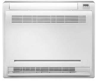
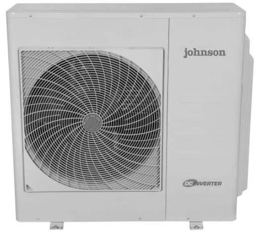
5 2. External Appearance 2.1 Indoor Units External Appearance DKH Duct Four-way cassette(compact) Console 2.2 Outdoor Units General Information 3
6 Product specification 3. Product specification Model Outdoor Unit Installation Method of Pipe Installation Method of Pipe Characteristics Units Cooling JOAU-ZCY218-H11 2 x JOSI-DKH009-N11 Flared Capacity (1) kw Heating Average Pdesign kw SEER / SCOP (2) W/W Energy efficiency class A+ A Annual energy consumption kwh Tbiv o C N/A -7 Tol o C N/A -15 Power supply V/Ph/Hz V/Single/50Hz Circuit breaker rating A 25 Rated power input (Maximum power input) kw 3.2 Rated current (Maximum current) A 14.5 OUTDOOR Refrigerant control Compressor type. model Capillary+EXV Twin Rotary DC Inverter Fan type & quantity Axial x 1 Fan speeds H/L RPM 750 Air flow H/L m3/hr 2500 Sound power level (4) H/L db(a) 65 Sound pressure level (5) H/L db(a) 55 Dimensions WxHxD mm 845x700x320 Weight kg 48 Package dimensions LxWxH mm 965x395x755 Packaged weight kg 52 Stacking height units 2 levels Refrigerant type R410A Refrigerant charge (standard connecting tubing length) kg(10m) 1.9 Additional charge per 1 meter gr / 1m 10m<L<20m 15g/m Liquid line In.(mm) 2x1/4 (Φ6.35) Suction line In.(mm) 2x3/8 (Φ9.52) Max. length for all rooms m 30 Max. length for one indoor unit m 20 Connection Max. OU higher than IU m 10 s between height units difference between indoor and OU lower than IU m 15 outdoor unit Max. height difference between indoor units m 10 Operation control type Remote control 4 General Information
7 Product specification Model Outdoor Unit Installation Method of Pipe Installation Method of Pipe Characteristics Units Cooling JOAU-ZCY327-H11 3 x JOSI-DKH009-N11 Flared Heating Average Capacity (1) kw Pdesign kw SEER / SCOP (2) W/W Energy efficiency class A++ A Annual energy consumption kwh Tbiv o C N/A -7 Tol o C N/A -15 Power supply V/Ph/Hz V/Single/50Hz Circuit breaker rating A 25 Rated power input (Maximum power input) kw 3.6 Rated current (Maximum current) A 16.5 OUTDOOR Refrigerant control Compressor type. model Capillary+EXV Twin Rotary DC Inverter Fan type & quantity Axial x 1 Fan speeds H/L RPM 800 Air flow H/L m3/hr 3500 Sound power level (4) H/L db(a) 68 Sound pressure level (5) H/L db(a) 58 Dimensions WxHxD mm 900x860x315 Weight kg 62 Package dimensions LxWxH mm 1043x395x915 Packaged weight kg 67 Stacking height units 2 levels Refrigerant type R410A Refrigerant charge (standard connecting tubing length) kg(10m) 2.4 Additional charge per 1 meter gr / 1m 15m<L<25m 15g/m Liquid line In.(mm) 3x1/4 (Φ6.35) Suction line In.(mm) 3x3/8 (Φ9.52) Max. length for all rooms m 45 Max. length for one indoor unit m 25 Connections between Max. height OU higher than IU m 10 units difference between indoor and OU lower than IU m 15 outdoor unit Max. height difference between indoor units m 10 Operation control type Remote control General Information 5
8 Product specification Model Outdoor Unit Installation Method of Pipe Installation Method of Pipe Characteristics Units Cooling JOAU-ZCY430-H11 4 x JOSI-DKH009-N11 Flared Capacity (1) kw Heating Average Pdesign kw SEER / SCOP (2) W/W Energy efficiency class A+ A Annual energy consumption kwh Tbiv o C N/A -7 Tol o C N/A -15 Power supply V/Ph/Hz V/Single/50Hz Circuit breaker rating A 25 Rated power input (Maximum power input) kw 3.7 Rated current (Maximum current) A 17 OUTDOOR Refrigerant control Compressor type. model Capillary+EXV Twin Rotary DC Inverter Fan type & quantity Axial x 1 Fan speeds H/L RPM 800 Air flow H/L m3/hr 3800 Sound power level (4) H/L db(a) 70 Sound pressure level (5) H/L db(a) 58 Dimensions WxHxD mm 900x860x315 Weight kg 65 Package dimensions LxWxH mm 1043x395x915 Packaged weight kg 69 Stacking height units 2 levels Refrigerant type R410A Refrigerant charge (standard connecting tubing length) kg(10m) 2.4 Additional charge per 1 meter gr / 1m 20m<L<30m 15g/m Liquid line In.(mm) 4x1/4 (Φ6.35) Suction line In.(mm) 4x3/8 (Φ9.52) Max. length for all rooms m 60 Max. length for one indoor unit m 30 Connections between Max. height OU higher than IU m 10 units difference between indoor and OU lower than IU m 15 outdoor unit Max. height difference between indoor units m 10 Operation control type Remote control 6 General Information
9 Model Outdoor Unit Installation Method of Pipe Installation Method of Pipe Characteristics Units Cooling JOAU-ZCY536-H11 5 x JOSI-DKH009-N11 Flared Product specification Heating Average Capacity (1) kw Pdesign kw SEER / SCOP (2) W/W Energy efficiency class A A Annual energy consumption kwh Tbiv o C N/A -7 Tol o C N/A -15 Power supply V/Ph/Hz V/Single/50Hz Circuit breaker rating A 32 Rated power input (Maximum power input) kw 4.9 Rated current (Maximum current) A 22 OUTDOOR Refrigerant control Compressor type. model Capillary +EXV Twin Rotary DC Inverter Fan type & quantity Axial x 1 Fan speeds H/L RPM 850 Air flow H/L m3/hr 5500 Sound power level (4) H/L db(a) 70 Sound pressure level (5) H/L db(a) 60 Dimensions WxHxD mm 990x345x965 Weight kg 80 Package dimensions LxWxH mm 1120x435x1100 Packaged weight kg 91 Stacking height units 2 levels Refrigerant type Refrigerant charge (standard connecting tubing length) kg(10m) 3 R410A Additional charge per 1 meter gr / 1m 25m<L<30m 15g/m Liquid line In.(mm) 5x1/4 (Φ6.35) Suction line In.(mm) 5x3/8 (Φ9.52) Max. length for all rooms m 75 Max. length for one indoor unit m 30 Connections between Max. height OU higher than IU m 10 units difference between indoor and OU lower than IU m 15 outdoor unit Max. height difference between indoor units m 10 Operation control type Remote control General Information 7
10 Product specification Model Indoor Unit JOSI-DKH009-N11 JOSI-DKH012-N11 Installation Method of Pipe Flared Flared Characteristics Units Cooling Heating Cooling Heating Capacity (4) kw 2.65( ) 2.8( ) 3.54( ) 3.5( ) Power supply INDOOR V Ph 1 1 Hz Fan type & quantity Crossflow x 1 Crossflow x 1 Cooling H/M/L/VL RPM 1150 / 1000 / / 1050 / 800 Fan speeds Heating H/M/L/VL RPM 1150 / 1000 / / 1050 / 800 Air flow (1) H/M/L/VL m3/hr 430/380/320/ /430/390 /310 External static pressure Min Pa 0 0 Sound power level (2) db(a) Sound pressure level(3) H/M/L/VL db(a) 38/35/31/22 36/32/29/23 Moisture removal l/hr 1,0 1.2 Condensate drain tube I.D mm ODΦ17.5 ODΦ17.5 Dimensions WxHxD mm 715x250x x275x188 Net Weight kg Package dimensions LxWxH mm 775x260x x265x350 Packaged weight kg Operation control type Remote control Remote control Model Indoor Unit JOSI-DKH018-N11 Installation Method of Pipe Flared Characteristics Units Cooling Heating Capacity (4) kw 5.0( ) 5.0( ) V Power supply Ph 1 Hz 50 Fan type & quantity Crossflow x 1 Fan speeds Cooling H/M/L/VL RPM 1100 / 800 / 700 Heating H/M/L/VL RPM 1100 / 800 / 700 Air flow (1) H/M/L/VL m3/hr 610/540/460/360 External static pressure Min Pa 0 INDOOR Sound power level (2) db(a) 57 Sound pressure level(3) H/M/L/VL db(a) 36/33/29/23 Moisture removal l/hr 1,7 Condensate drain tube I.D mm ODΦ17.5 Dimensions WxHxD mm 940x275x205 Net Weight kg 9 Package dimensions LxWxH mm 1015x265x350 Packaged weight kg 12.2 Operation control type Remote control 8 General Information
11 Product specification Model Indoor Unit JOSI-DAQ012-N11 JOSI-DCD012-N11 Installation Method of Pipe Flared Flared Characteristics Units Cooling Heating Cooling Heating Capacity (4) kw V Power supply Ph 1 1 Hz Fan type & quantity Centrifugal fan x1 Centrifugal fan x2 Fan speeds Cooling H/M/L/VL RPM 810/780/680/ /1070/1000 Heating H/M/L/VL RPM 810/780/680/ /1070/1000 Air flow (1) H/M/L/VL m3/hr 700/640/560/ /440/410 External static pressure Min Pa 0 25(0~40) INDOOR Sound power level (2) db(a) Sound pressure level(3) H/M/L/VL db(a) 44/40/36 41/39/36 Moisture removal l/hr 1,5 1.5 Condensate drain tube I.D mm ODФ16 ODΦ25 Dimensions WxHxD mm x210x635 Net Weight kg Package dimensions LxWxH mm x655x290 Packaged weight kg Operation control type Remote control Wired remote control General Information 9
12 Product specification Model Indoor Unit JOSI-DBC012-N11 Installation Method of Pipe Flared Characteristics Units Cooling Heating Capacity (4) kw V Power supply Ph 1 Hz 50 Fan type & quantity Centrifugal fan x1 Fan speeds Cooling H/M/L/VL RPM 830/720/660 Heating H/M/L/VL RPM 830/720/660 Air flow (1) H/M/L/VL m3/hr 800/710/560 External static pressure Min Pa 0 Sound power level (2) db(a) 55 Sound pressure level(3) H/M/L/VL db(a) 44/41/38 INDOOR Moisture removal l/hr 1.5 Condensate drain tube I.D mm ODΦ25 Dimensions WxHxD mm 570x260x570 Net Weight kg 16 Package dimensions LxWxH mm 655x655x290 Packaged weight kg 19 Frame dimensions WxHxD mm 647x50x647 Frame net weight kg 2.5 Frame package dimensions LxWxH mm 715x715x123 Frame packaged weight kg 4.5 Operation control type Remote control 10 General Information
13 Indoor Units Part 2 Indoor Units DKH Type Light Commercial Indoor Units 11
14 DKH Type DKH Type 1. Function Dimensions Wiring Diagrams Exploded View and Spare Part list Indoor Units
15 1. Function Function Filter 2 ways of drainage Killer Of Formaldehyde Louver Position Memory Function Ionizer(O) Refrigerant Leakage Detect Silver Ico Filter(O) Self-diag. Function Vitamin C Filter(O) Hydrophilic Aluminum Fin 3M HAM Filter(O) PTC Heating Belt(O) Bio Filter(O) Golden Fin(O) 1W Standby O: optional function Indoor Units 13
16 Dimensions 2. Dimensions H W D Model W D H JOSI-DKH009-N JOSI-DKH012-N JOSI-DKH018-N Model L(mm) R(mm) H(mm) JOSI-DKH009-N11 JOSI-DKH012-N JOSI-DKH018-N Dimension of installation hole(mm) Indoor Units
17 3. Wiring Diagrams JOSI-DKH009-N11, JOSI-DKH012-N11, JOSI-DKH018-N11 Wiring Diagrams Indoor Units 15
18 Exploded View and Spare Part list 4. Exploded View and Spare Part list Exploded View of indoor unit: JOSI-DKH009-N11 16 Indoor Units
19 Exploded View and Spare Part list Spare part list of indoor unit: JOSI-DKH009-N11. BOM Code Part Name Quantity A01165 Panel assembly Filter A00826 Structure Subassembly of Display Box A02198 VLED Display Module E-Parts Cover Plate frame assembly Screw Cap Drain Hose Brass Nut Brass Nut Temperature Sensing Element Fixing clip Evaporator assembly Gas valve assembly Motor Bearing Cover Brushless DC Motor Bearing sleeve Bearing pedestal Cross-flow window rotor Wind Guide Assembly Chassis Assembly stepper motor Pipe Pressing Board Installation Plate A18108 Electronic control box assembly Electrical Control Box Electrical Control Box Indoor main control board assembly Room Temperature Sensor Temperature Sensor A00046 Wire holder Electrical Control Box Cover A15640 Remote controller Seal Extend Water Pipe Filter net of cold catalyst Kit of Screw Accessories 1 Indoor Units 17
20 Exploded View and Spare Part list Exploded View of indoor unit: JOSI-DKH012-N11 18 Indoor Units
21 Exploded View and Spare Part list Spare part list of indoor unit: JOSI-DKH012-N11. BOM Code Part Name Quantity A00987 Panel assembly A00826 Structure Subassembly of Display Box A02198 VLED Display Module E-Parts Cover Plate frame assembly Screw Cap Drain Hose Brass Nut Brass Nut Temperature Sensing Element Fixing clip Evaporator assembly Motor Bearing Cover Brushless DC Motor Bearing sleeve Bearing pedestal Cross-flow Window Rotor Wind Guide Assembly Chassis Assembly stepper motor Pipe Pressing Board Installation Plate A18111 Electronic control box assembly Electrical Control Box Electrical Control Box Indoor main control board assembly Room Temperature Sensor Temperature Sensor A00046 Wire holder Electrical Control Box Cover A15640 Remote controller Seal Extend Water Pipe Filter net of cold catalyst Air filter Right side of the filter Kit of Screw Accessories 1 Indoor Units 19
22 Exploded View and Spare Part list Exploded View of indoor unit: JOSI-DKH018-N11 20 Indoor Units
23 Exploded View and Spare Part list Spare part list of indoor unit: JOSI-DKH018-N11. BOM Code Part Name Quantity A00937 Panel assembly Filter A00996 Structure Subassembly of Display Box A02198 VLED Display Module E-Parts Cover Plate Panel frame assembly Screw Cap Drain Hose Brass Nut Brass Nut Temperature Sensing Element Fixing clip Evaporator assembly Motor Bearing Cover Brushless DC Motor Bearing sleeve Bearing pedestal Cross-flow window rotor Wind Guide Chassis Assembly stepper motor Pipe Pressing Board Installation Plate A18109 Electronic control box assembly Electrical Control Box Electrical Control Box Indoor main control board assembly Room Temperature Sensor Temperature Sensor Wire holder Electrical Control Box Cover A15640 Remote controller Seal Extend Water Pipe Filter net of cold catalyst Kit of Screw Accessories 1 Indoor Units 21
24 Light Commercial Light Commercial 1. Features Dimensions Service Space(unit:mm) Wiring Diagrams Exploded View and Spare Part list Indoor Units
 ⑴ New panel 360 surrounding air outlet design, affords comfortable feeling")

25 1. Features 1.1 Four-way cassette type(compact) ⑴ New panel 360 surrounding air outlet design, affords comfortable feeling Features ⑵ Compact design The body size is mm, it s just smaller than the ceiling board, so it s very easy for installation and will not damage the decoration. The panel size is mm. The hooks are designed in the four corners of the body, which can save installation space. Light Commercial 23


26 Features ⑶ Electric control box built-in design The E-box is simply and safely built inside the indoor unit. It s convenient for installation and maintenance. Can check the control part easily, you only need to open the air return grille. ⑷ Fresh air intake function: Fresh air fulfills air quality more healthy and comfortable. 24 Indoor Units


27 Features Fresh Air Dimension:Φ75mm ⑸ Air passage function Reserves the space for air outlet from the side of indoor unit; It s availed to connect air duct from the two sides to the nearby small rooms. Light Commercial 25
 Front Board, Canvas Air Passage,")
 Air inlet from")


28 Features 1.2 A5 Duct ⑴ Installation accessories: (Optional) Front Board, Canvas Air Passage, Filter, Panel, for easy installation Front Board Canvas Air Passage Filter Panel ⑵ Easy Installation: Two air inlet styles (Bottom side or Rear side) Air inlet from rear is standard for all capacity; air inlet from bottom is optional. The size of air inlet frame from rear and bottom is same, it s very easy to move the cover from bottom to rear side, or from rear to the bottom, in order to matching the installation condition. Air intake from rear (Standard) Air intake from bottom (Optional) ⑶ Fresh air intake function Install one duct from the reserved fresh-air intake to outdoor. Continually inhale the fresh air to improve the quality of the indoor air, fulfills air quality more healthy and comfortable. 26 Indoor Units
 It is easy to draw out the filter from the indoor unit for")


29 Features ⑷ Easy maintenance Clean the filter (Optional, standard product without filter) It is easy to draw out the filter from the indoor unit for cleaning, even the filter is installed in rear side or bottom side. Replace the motor or centrifugal fan Remove the ventilated panel firstly. Remove a half of blower housing and take out the motor with centrifugal fan. Directly remove two bolts, and then replace the motor or centrifugal fan easily. Light Commercial 27

: Built-in drain pump can lift the water to 750mm")
30 Features Motor Blower Housing Ventilated Panel ⑸ Reserved remote on-off and central control ports Reserved remote on-off ports and central control ports, can connect the cable of an on-off controller or a central controller to realize remote on-off control function or group control function. Remote on-off ports Central control ports ⑹ Built-in drain pump (Optional): Built-in drain pump can lift the water to 750mm upmost. It s convenient to install drainage piping under most space condition. 28 Indoor Units


31 Features 750mm upmost ⑺ Built-in display board The standard indoor unit can be controlled by wired controller. There is a display board with a receiver in the E-box. Move out the display, and fix it in other place, even in the distance of 10m. The unit will realized remoter control. The wired controller and the display board can display the error code or production code when the chips detect some failure. Wired Controller (Standard) Remote Controller (Optional) Light Commercial 29
 Consumes up to 30% less energy than non-inverter units DC inverter compressor indoor fan motor adopts DC motor (2) Achieves set")
32 Features Display 1.3 Console (1) Consumes up to 30% less energy than non-inverter units DC inverter compressor indoor fan motor adopts DC motor (2) Achieves set temperature more quickly air supplying from top and bottom or from top only air inlet from four directions 30 Indoor Units

 Comfort flexible air blow: vertical auto swing and wide angle louvers ensure that warm air reaches the furthest corners of the room and increase the air flow coverage Low noise operation, lowest")
33 Features (3) Compact unit body, space saving this unit body is very thin and harmonious with room. It is beautiful, elegant and space saving. lightweight and compact. (4) Flexible installation. can be used for floor standing or lower wall applications as a floor standing floor model, it can be semi or fully recessed without loss of capacity. (5) High efficiency filter built in Formaldehyde nemesis filter active-carbon and biological anti-virus filter is optional. (6) Comfort flexible air blow: vertical auto swing and wide angle louvers ensure that warm air reaches the furthest corners of the room and increase the air flow coverage Low noise operation, lowest to 23Db Low starting power and precise room temperature adjustment (7) Powerful mode can be selected for rapid cooling or heating. (8) Easy cleaning grille and maintenance (9) Indoor unit adopts DC motor, it has five level fan speed meet different requirements. Light Commercial 31
: 2.")
34 Dimensions 2. Dimensions 2.1 Four-way cassette type(compact): 2.2 A5 Duct H G B E F A D C 32 Indoor Units
35 Dimensions M L Model Outline dimension(mm) Air outlet opening size Air return opening size Size of outline dimension mounted plug A B C D E F G H I J K L M JOSI-DCD012-N Console Light Commercial 33
36 Dimensions 34 Indoor Units
37 3. Service Space(unit:mm) 3.1 Four-way cassette(compact) Service Space(unit:mm) 3.2 A5 Duct Ensure enough space required for installation and maintenance. All the indoor units reserve the hole to joint the fresh air pipe. The hole size as following: Light Commercial 35

38 Service Space(unit:mm) 3.3 Console 36 Indoor Units
 ON OFF Fan OFF when ICT<15 OFF ON Fan OFF when ICT<8 ON ON Reserved SW6-1 SW6-2 Temp.")
39 4. Wiring Diagrams Wiring Diagrams JOSI-DBC012-N11(7SP042243) S2 S1(1-2) Address (Central control) 0-F OFF-OFF 0-15(Default=0) 0-F ON-OFF F OFF-ON F ON-ON SW1-1 SW1-2 Anti Cold Air Setting OFF OFF Fan OFF when ICT<24(Default) ON OFF Fan OFF when ICT<15 OFF ON Fan OFF when ICT<8 ON ON Reserved SW6-1 SW6-2 Temp. Compensation (Heating) OFF OFF 6(Default) ON OFF 4 OFF ON 2 ON ON Reserved SW3 OFF ON SW2 OFF ON Auto Restart With Auto Restart (Default) W/O Auto Restart Fan Status When Thermo-OFF FAN ON(Default) FAN OFF Y/G M 5 RCW8(Optional) RCW6 (Optional) P5 4 CN15 CN13 CH CN5 10 H 5 Alarm Output ALARM CN33 Remote Control INDOOR UNIT MAINBOARD CN3 To Central Control CN1 JR6 JR6 TO OUTDOOR UNIT Fresh Air M CN8 Y/G JOSI-DCD012-N11 Light Commercial 37

40 Wiring Diagrams JOSI-DCD012-N11 JOSI-DAQ012-N11 38 Indoor Units
41 Exploded View and Spare Part list 1. Exploded View and Spare Part list Exploded View of indoor unit:josi-dbc012-n11 40 Indoor Units
42 Exploded View and Spare Part list Spare part list of indoor unit:josi-dbc012-n11. BOM Code Part Name Quantity Water receiver assembly Line pressing box A00260 Evaporator assembly Gas valve assembly Evaporator Brass Nut Outlet Pipes of Evaporator Input pipes of Evaporator assembly Joint board of 1 Evaporator Brass Nut Temperature Sensor Evaporator Fixing hanger Chassis Foam Subassembly Chassis Assembly Installation Hanger Installation Hanger Installation Hanger Installation Hanger Sealing board for Pipe Tie-in Subassembly Joint board of Evaporator Motor Installing Foundation Brushless DC Motor Centrifugal Fan Air Guide Coil E-Parts Box assembly Welding Parts of Electrical Control Box Wiring baseplate Indoor Main Control Board Subassembly (Sticker) Wire holder Line pressing card Room Temperature Sensor Electrical Control Box Cover Subassembly A15640 Remote controller Water Level Switch Induction pump Rubber Gasket of Water Drain Pump Drain pump rubber washer II Installing Plate of Water Drain Pump(RoHS) Drain pipe Drain pipe 1 Light Commercial 41
43 Exploded View and Spare Part list Exploded View of indoor unit: JOSI-DCD012-N11 42 Indoor Units
44 Exploded View and Spare Part list Spare part list of indoor unit: JOSI-DCD012-N11. BOM Code Part Name Quantity Chassis assembly Up volute shell Centrifugal fan Below volute shell Fan motor axes clamp (left) Fan motor fixing board Fan motor axes clamp (right) Asynchronous motor Supporter of fan motor Middle beam assembly Left clapboard assembly Hook Evaporator assembly Output pipe assembly Copper nut Input pipe assembly Copper nut Evaporator right support board assembly Pipe temperature sensor assembly Water collector Right clapboard assembly Hook Electronic control box assembly Electronic control box Wire joint Ambient temperature sensor assembly Main control board assembly Cover of electronic control box Pipe clamp board assembly A0077 Display box assembly Display board assembly A07946 Wired controller Rear beam Rear cover assembly Top cover assembly 1 Light Commercial 43
45 Exploded View and Spare Part list Exploded View of indoor unit:josi-daq012-n11 44 Indoor Units
46 Exploded View and Spare Part list Spare part list of indoor unit:josi-daq012-n11. BOM Code Part Name Quantity A0001 Panel assembly Air filter Panel frame assembly Evaporator assembly Pipe temperature sensor assembly Ventilation assembly Chassis assembly Hang board assembly Anti-bacterial filter Bracket of air filter A0034 Electronic control box assembly Installation plate of electric parts I Electrical control box Fixing board of electronic control box II Ambient temperature sensor assembly Wire joint Electronic control box seal plate Installation plate of electric parts Display board assembly A0029 Main control board assembly Fixing board of electronic control box I Auxiliary electric heater control board Water collector Louver motor P Underside louver Air outlet assembly Louver motor Rear net P Up louver Pipe clamp Installation clamp A15640 Remote controller Insulation washer Cover of electronic control box Centrifugal fan Fan motor Supporter assembly of fan motor 1 Light Commercial 45
47 Outdoor Units Part 3 Outdoor Units 1. Dimensions Service Space Refrigeration Cycle Diagram Wiring Diagrams Indoor units combination Operation Limits Sound Levels Exploded View and Spare Part list Outdoor Units
48 Dimensions 1. Dimensions JOSI-DAQ012-N L L2 700 H 6 D1 335 D W1 845 W W2 73 D3 B2 110 B1 120 D H1 R6 A2 50 A1 22 R5 110 H2 Outdoor Units 47
49 Dimensions JOAU-ZCY327-H L L2 860 H 12 D1 333 D W1 900 W D3 B2 B1 97 D W H1 A2 50 R6 110 H2 48 Outdoor Units
50 JOAU-ZCY430-H11 Dimensions L L2 860 H 12 D1 333 D W1 900 W D3 B2 B1 97 D W H1 A2 50 R6 110 H2 Outdoor Units 49
51 Dimensions JOAU-ZCY536-H11 50 Outdoor Units
52 Service Space 2. Service Space (Wall or obstacle) Air inlet More than 30cm Air inlet Air outlet More than 30cm Maintain channel More than 60cm More than 200cm More than 60cm Outdoor Units 51
53 Refrigeration Cycle Diagram 3. Refrigeration Cycle Diagram 3.1 Refrigeration cycle diagram of inverter 1 drive 2 type INDOOR OUTDOOR LIQUID VALVE A EXV A CAPILIARY A CHECK VALVE LIQUID VALVE B EXV B CAPILIARY B CAPILIARY TUBE T3 Condenser temp. sensor HEAT EXCHANGE (EVAPORATOR) T1 Room temp. sensor T4 Ambient temp. sensor HEAT EXCHANGE (CONDENSER) T2 Evaporator temp. sensor middle GAS VALVE A GAS VALVE B T2B-A Evaporator temp. sensor outlet T2B-B 4-WAY VALVE Accumulator Compressor T5 Discharge temp. sensor COOLING HEATING 3.2 Refrigeration cycle diagram of inverter 1 drive 3 type INDOOR OUTDOOR LIQUID VALVE A EXV A CAPILIARY A LIQUID VALVE B EXV B CAPILIARY B CHECK VALVE LIQUID VALVE C EXV C CAPILIARY C CAPILIARY TUBE T3 Condenser temp. sensor HEAT EXCHANGE (EVAPORATOR) T1 Room temp. sensor T4 Ambient temp. sensor HEAT EXCHANGE (CONDENSER) T2 Evaporator temp. sensor middle GAS VALVE A GAS VALVE B T2B-A Evaporator temp. sensor outlet T2B-B 4-WAY VALVE GAS VALVE C T2B-C Accumulator Compressor T5 Discharge temp. sensor COOLING HEATING 3.3 Refrigeration cycle diagram of inverter 1 drive 4 type 52 Outdoor Units
54 Diagram INDOOR OUTDOOR Refrigeration Cycle LIQUID VALVE A EXV A CAPILIARY A LIQUID VALVE B EXV B CAPILIARY B CHECK VALVE LIQUID VALVE C LIQUID VALVE D EXV C CAPILIARY C EXV D CAPILIARY D CAPILIARY TUBE T3 Condenser temp. sensor HEAT EXCHANGE (EVAPORATOR) T1 Room temp. sensor T4 Ambient temp. sensor HEAT EXCHANGE (CONDENSER) GAS VALVE A T2B-A Evaporator temp. sensor outlet T2 Evaporator temp. sensor middle GAS VALVE B GAS VALVE C GAS VALVE D T2B-B T2B-C T2B-D Accumulator Low pressure switch Compressor 4-WAY VALVE High pressure switch T5 Discharge temp. sensor COOLING HEATING 3.4 Refrigeration cycle diagram of inverter 1 drive 5 type INDOOR OUTDOOR LIQUID VALVE A EXV A CAPILIARY A LIQUID VALVE B EXV B CAPILIARY B LIQUID VALVE C EXV C CAPILIARY C CHECK VALVE LIQUID VALVE D LIQUID VALVE E EXV D CAPILIARY D EXV E CAPILIARY E CAPILIARY TUBE T3 Condenser temp. sensor HEAT EXCHANGE (EVAPORATOR) T1 Room temp. sensor GAS VALVE A T2B-A Evaporator temp. sensor outlet T4 Ambient temp. sensor HEAT EXCHANGE (CONDENSER) T2 Evaporator temp. sensor middle GAS VALVE B GAS VALVE C GAS VALVE D GAS VALVE E T2B-B T2B-C T2B-D T2B-E Accumulator Low pressure switch Compressor 4-WAY VALVE High pressure switch T5 Discharge temp. sensor COOLING HEATING Outdoor Units 53
55 Wiring Diagrams 4. Wiring Diagrams JOAU-ZCY218-H11 JOAU-ZCY327-H11 54 Outdoor Units
56 JOAU-ZCY430-H11 Wiring Diagrams JOAU-ZCY536-H11 Outdoor Units 55
57 Indoor units combination 5. Indoor units combination 5.1 Indoor unit combination for JOAU-ZCY218-H11 JOAU-ZCY218-H11 Two IDU Indoor unit combination for JOAU-ZCY327-H11 JOAU-ZCY327-H11 Two IDU Three IDU Indoor unit combination for JOAU-ZCY430-H11 JOAU-ZCY430-H11 Two IDU Three IDU Four IDU Indoor unit combination for JOAU-ZCY536-H11 JOAU-ZCY536-H11 Two IDU Three IDU Four IDU Five IDU Outdoor Units
58 Operation Limits 6. Operation Limits Mode Temperature Cooling operation Heating operation CAUTION: Room temperature Outdoor temperature 0 ~50-15 ~50 (For the models with low temperature cooling system) -15 ~24 1. If the air conditioner is used beyond the above conditions, certain safety protection features may come into operation and cause the unit to operate abnormally. 2. The room relative humidity should be less than 80%. If the air conditioner operates beyond this figure, the surface of the air conditioner may attract condensation. Please set the vertical air flow louver to its maximum angle (vertically to the floor), and set HIGH fan mode. 3. The optimum performance will be achieved during this operating temperature zone. Outdoor Units 57
59 Sound Levels 7. Sound Levels Outdoor Unit Microphone H 1.0m te: H= 0.5 height of outdoor unit Model ise Power db(a) ise level db(a) JOAU-ZCY218-H JOAU-ZCY327-H JOAU-ZCY430-H JOAU-ZCY536-H Outdoor Units
60 Spare Part list Exploded View and 8. Exploded View and Spare Part list Exploded View of outdoor unit: JOAU-ZCY218-H11 Outdoor Units 59
61 Exploded View and Spare Part list Spare part list of outdoor unit: JOAU-ZCY218-H11. Part Name Qty BOM Code. Part Name Qty BOM Code 1 Ambient temperature sensor assembly Rear net G Condenser assembly Input pipe assembly Condenser Output pipe Pipe temperature sensor assembly Pipe temperature sensor assembly Partition assembly board Electronic control box assembly Cover of electronic control box Outdoor main control board assembly Inverter control board assembly Installation plate of electric parts Radiator Terminal assembly board Valve plate Wire joint Chassis assembly Terminal board Rear right clapboard assembly Liquid valve assembly Water collector Liquid valve Front right clapboard assembly Front panel Electronic expansion valve assembly 4-ways assembly valve Air outlet grille A Gas valve Round sticker of air outlet grille A ways valve Axial flow fan Compressor Brushless DC Motor Supporter assembly of fan motor Discharge temperature assembly sensor Cover of inductance Rear supporter Reactor Top cover assembly Copper nut Left supporter Partition assembly board Outdoor Units
62 Spare Part list Exploded View of outdoor unit: JOAU-ZCY327-H11 Exploded View and Outdoor Units 61
63 Exploded View and Spare Part list Spare part list of outdoor unit: JOAU-ZCY327-H11. Part Name Qty BOM Code. Part Name Qty BOM Code 1 Ambient temperature sensor assembly 2 Rear net G Radiator Terminal assembly board Condenser assembly Wire joint Pipe temperature sensor assembly Pipe temperature sensor assembly Terminal board Liquid valve assembly Valve plate Liquid valve Chassis assembly Rear right clapboard assembly Electronic expansion valve assembly Liquid valve assembly Water collector Liquid valve Front right clapboard assembly Electronic expansion valve assembly Front panel Liquid valve assembly Air outlet grille A Liquid valve Round sticker of air outlet grille A Axial flow fan Electronic expansion valve assembly 4-ways valve assembly Brushless DC Motor Gas valve Supporter assembly of fan motor ways valve Rear supporter Capillary assembly Top cover assembly Compressor Left supporter Partition assembly board Electronic control box assembly Cover of electronic control box Outdoor main control board assembly Inverter control board assembly Electronic box installing Discharge temperature assembly sensor Cover of inductance Reactor Reactor Handle Accumulator cylinder Outdoor Units
64 Spare Part list Exploded View of outdoor unit: JOAU-ZCY430-H11 Exploded View and Outdoor Units 63
65 Exploded View and Spare Part list Spare part list of outdoor unit: JOAU-ZCY430-H11. Part Name Qty BOM Code. Part Name Qty BOM Code 1 Ambient temperature sensor assembly Terminal board Rear net G Liquid valve assembly Condenser assembly Liquid valve Pipe temperature sensor assembly Pipe temperature sensor assembly Electronic expansion valve assembly Liquid valve assembly Valve plate Liquid valve Chassis assembly Rear right clapboard assembly Electronic expansion valve assembly Liquid valve assembly Water collector Liquid valve Front right clapboard assembly Front panel Electronic expansion valve assembly 4-ways assembly valve Air outlet grille A Gas valve Round sticker of air A ways valve outlet grille 1 13 Axial flow fan Capillary assembly Brushless DC Motor Compressor Supporter assembly Discharge of fan motor temperature sensor assembly 16 Rear supporter Cover of inductance Top cover assembly Reactor Left supporter Reactor Partition assembly board Electronic control box assembly Cover of electronic control box Outdoor main control board assembly Inverter control board assembly Installation plate of electric parts Handle Accumulator cylinder Liquid valve assembly Liquid valve Electronic expansion valve assembly Suction assembly pipe Radiator Pressure switch Terminal assembly board Terminal board Wire joint Liquid valve assembly Wire joint Outdoor Units
66 Exploded View and Spare Part list Exploded View of outdoor unit: JOAU-ZCY536-H11 66 Outdoor Units
67 Spare Part list Exploded View and Spare part list of outdoor unit: JOAU-ZCY536-H11. Part Name Qty BOM Code. Part Name Qty BOM Code 1 Rear net G Ambient temperature sensor assembly Electronic installing box assembly Active PFC Module Subassembly Condenser assembly Compressor Input pipe assembly Discharge temperature sensor assembly 3.2 Condenser Ways valve assembly Condenser Gas valve Output pipe Ways valve Pipe temperature sensor assembly Pressure switch Pipe temperature sensor assembly liquid valve assembly Big handle Liquid valve Rear right clapboard assembly Electronic expansion valve assembly Valve plate liquid valve assembly Chassis assembly Liquid valve Front right clapboard assembly Electronic expansion valve assembly Air outlet grille A liquid valve assembly Round sticker of air outlet grille 12 Front panel A Liquid valve Electronic expansion valve assembly Rear supporter G liquid valve assembly Top cover assembly Liquid valve Axial flow fan Brushless DC Motor Supporter assembly of fan motor Electronic expansion valve assembly Suction assembly pipe Pressure switch Left supporter Capillary assembly Partition assembly board Electronic control box assembly Inverter control board assembly Accumulator cylinder Fix clamp of segregator PFC Inductor Rectifier bridge Magnetic Loop Outdoor main control board assembly Installation plate of electric parts 21.5 Wire joint liquid valve assembly Liquid valve Electronic expansion valve assembly Wire joint Cover of inductance Radiator Reactor Outdoor Units 67
68 Installation Part 4 Installation 1.Wrench torque sheet for installation Connecting the cables Pipe length and the elevation Installation for the first time Adding the refrigerant after running the system for many years Re-installation while the indoor unit need to be repaired Re-installation while the outdoor unit need to be repaired Installation
69 Wrench torque sheet for installation 1. Wrench torque sheet for installation Outside diameter Torque Additional tightening torque mm N.cm N.cm Ф (153kgf.cm) 1600(163kgf.cm) Ф (255kgf.cm) 2600(265kgf.cm) Ф (357kgf.cm) 3600(367kgf.cm) 2. Connecting the cables The power cord of connect should be selected according to the following specifications sheet. Rated current of appliance minal cross-sectional area (mm²) >3 and >6 and 10 1 >10 and >16 and The cable size and the current of the fuse or switch are determined by the maximum current indicated on the nameplate which located on the side panel of the unit. Please refer to the nameplate before selecting the cable, fuse and switch. 3. Pipe length and the elevation Maximum piping length and height difference 1 drive 2 1 drive 3 1 drive 4 1 drive 5 Max. length for all rooms (m) Max. length for one IU (m) Max. height difference between IU and OU (m) OU higher than IU OU lower than IU Max. height difference between IUs (m) Additional refrigerant charge 1 drive 2 1 drive 3 1 drive 4 1 drive 5 Chargeless pipe length (m) Additional refrigerant charge (g) 15 x (length for all rooms - 10) 15 x (length for all rooms - 15) 15 x (length for all rooms - 20) 15 x (length for all rooms - 25) Caution: Refrigerant pipe diameter is different according to indoor unit to be connected. When using the extension pipe, refer to the tables below. When refrigerant pipe diameter is different from that of outdoor unit union (for 18K indoor unit), additional transfer connector needs to be used on outdoor unit union. Installation 69
70 Pipe length and the elevation Indoor unit Model Pipe diameter (mm/inch) Extension pipe diameter (mm/inch) 7K9K12K Liquid 6.35(1/4) Liquid 6.35(1/4) Gas 9.52(3/8) Gas 9.52(3/8) 18K Liquid 6.35(1/4) Liquid 6.35(1/4) Gas 12.7(1/2) Gas 12.7(1/2) Outdoor unit union diameter (mm/inch) Indoor unit A/B/C/D Liquid 6.35(1/4) Gas 9.52(3/8) 70 Installation
71 4. Installation for the first time Air and moisture in the refrigerant system have undesirable effects as below: Pressure in the system rises. Operating current rises. Cooling or heating efficiency drops. Moisture in the refrigerant circuit may freeze and block capillary tubing. Installation for the first time Water may lead to corrosion of parts in the refrigerant system. Therefore, the indoor units and the pipes between indoor and outdoor units must be leak tested and evacuated to remove gas and moisture from the system. Gas leak check (Soap water method): Apply soap water or a liquid neutral detergent on the indoor unit connections or outdoor unit connections by a soft brush to check for leakage of the connecting points of the piping. If bubbles come out, the pipes have leakage Air purging with vacuum pump (Indoor unit) (Liquid side) (Outdoor unit) Two-way valve Close (Gas side) Manifold valve Compound meter Pressure gauge -0.1MPa Lo Hi Three-way valve Close Handle Lo Charge hose Handle Hi Charge hose Vacuum pump Vacuum pump 1) Completely tighten the flare nuts of the indoor and outdoor units, confirm that both the 2-way and 3-way valves are set to the closed position. 2) Connect the charge hose with the push pin of handle lo to the 3-way valves gas service port.. 3) Connect the charge hose of handle hi connection to the vacuum pump. 4) Fully open the handle Lo of the manifold valve. 5) Operate the vacuum pump to evacuate. 6) Make evacuation for 30 minutes and check whether the compound meter indicates -0.1Mpa. If the meter does not indicate -0.1Mpa after pumping 30 minutes, it should be pumped 20 minutes more. If the pressure can t achieve -0.1Mpa after pumping 50 minutes, please check if there are some leakage points. Fully close the handle Lo valve of the manifold valve and stop the operation of the vacuum pump. Confirm that the gauge needle does not move (approximately 5 minutes after turning off the vacuum pump). 7) Turn the flare nut of the 3-way valves about 45 counterclockwise for 6 or 7seconds after the gas Installation 71
72 Installation for the first time coming out, then tighten the flare nut again. Make sure the pressure display in the pressure indicator is a little higher than the atmosphere pressure. Then remove the charge hose from the 3 way valve. 8) Fully open the 2 way valve and 3 way valve and securely tighten the cap of the 3 way valve Air purging by refrigerant Procedure: 1). Confirm that both the 2-way and 3-way valves are set to the closed position. 2). Connect the charge set and a charging cylinder to the service port of the 3-way valve. 3). Air purging. Open the valves on the charging cylinder and the charge set. Purge the air by loosening the flare nut on the 2-way valve approximately 45 for 3 seconds then closing it for 1 minute; repeat 3 times. After purging the air, use a torque wrench to tighten the flare nut on the 2-way valve. 4). Check the gas leakage. Check the flare connections for gas leakage. 5). Discharge the refrigerant. Close the valve on the charging cylinder and discharge the refrigerant by loosening the flare nut on the 2-way valve approximately 45 until the gauge indicates 0.3 to 0.5 Mpa. 6). Disconnect the charge set and the charging cylinder, and set the 2-way and 3-way valves to the open position. Be sure to use a hexagonal wrench to operate the valve stems. 7). Mount the valve stems nuts and the service port cap. 72 Installation
73 Installation for the first time Be sure to use a torque wrench to tighten the service port cap to a torque 18N m. Be sure to check the gas leakage Adding the refrigerant if the pipe length >5m Electronic scale Procedure: 1). Connect the charge hose to the charging cylinder, open the 2-way valve and the 3-way valve. Connect the charge hose which you disconnected from the vacuum pump to the valve at the bottom of the cylinder. If the refrigerant is R410A, make the cylinder bottom up to ensure the liquid charge. 2). Purge the air from the charge hose. Open the valve at the bottom of the cylinder and press the check valve on the charge set to purge the air (be careful of the liquid refrigerant). 3) Put the charging cylinder onto the electronic scale and record the weight. 4) Operate the air conditioner at the cooling mode. 5) Open the valves (Low side) on the charge set and charge the system with liquid refrigerant. 6).When the electronic scale displays the proper weight (refer to the table), disconnect the charge hose from the 3-way valve s service port immediately and turn off the air conditioner before disconnecting the hose. 7). Mount the valve stem caps and the service port Use torque wrench to tighten the service port cap to a torque of 18N.m. Be sure to check for gas leakage. Installation 73
74 Adding the refrigerant after running the system for many years 5. Adding the refrigerant after running the system for many years Electronic scale Procedure: 1). Connect the charge hose to the 3-way service port, open the 2-way valve and the 3-way valve. Connect the charge hose to the valve at the bottom of the cylinder. If the refrigerant is R410A, make the cylinder bottom up to ensure liquid charge. 2). Purge the air from the charge hose. Open the valve at the bottom of the cylinder and press the check valve on the charge set to purge the air (be careful of the liquid refrigerant). 3) Put the charging cylinder onto the electronic scale and record the weight. 4) Operate the air conditioner at the cooling mode. 5) Open the valves (Low side) on the charge set and charge the system with liquid refrigerant. 6).When the electronic scale displays the proper weight (refer to the gauge and the pressure of the low side), disconnect the charge hose from the 3-way valve s service port immediately and turn off the air conditioner before disconnecting the hose. 7). Mount the valve stem caps and the service port Use torque wrench to tighten the service port cap to a torque of 18N.m. Be sure to check for gas leakage. 74 Installation
75 6. Re-installation while the indoor unit need to be repaired 6.1. Collecting the refrigerant into the outdoor unit Re-installation while the indoor unit need to be repaired Procedure 1). Confirm that both the 2-way and 3-way valves are set to the opened position Remove the valve stem caps and confirm that the valve stems are in the opened position. Be sure to use a hexagonal wrench to operate the valve stems. 2). Connect the charge hose with the push pin of handle lo to the 3-way valves gas service port. 3). Air purging of the charge hose. Open the handle Lo valve of the manifold valve slightly to purge air from the charge hose for 5 seconds and then close it quickly. 4). Set the 2-way valve to the close position. 5). Operate the air conditioner at the cooling cycle and stop it when the gauge indicates 0.1MPa. 6). Set the 3-way valve to the closed position immediately Do this quickly so that the gauge ends up indicating 0.3 to 0.5Mpa. Disconnect the charge set, and tighten the 2-way and 3-way valve s stem nuts. Use a torque wrench to tighten the 3-way valves service port cap to a torque of 1.8 kgf.m. Be sure to check for gas leakage. Installation 75
76 Re-installation while the indoor unit need to be repaired 6.2. Air purging by the refrigerant Procedure: 1). Confirm that both the 2-way and 3-way valves are set to the closed position. 2). Connect the charge set and a charging cylinder to the service port of the 3-way valve Leave the valve on the charging cylinder closed. 3). Air purging. Open the valves on the charging cylinder and the charge set. Purge the air by loosening the flare nut on the 2-way valve approximately 45 for 3 seconds then closing it for 1 minute; repeat 3 times. After purging the air, use a torque wrench to tighten the flare nut on the 2-way valve. 4). Check the gas leakage Check the flare connections for gas leakage. 5). Discharge the refrigerant. Close the valve on the charging cylinder and discharge the refrigerant by loosening the flare nut on the 2-way valve approximately 45 until the gauge indicates 0.3 to 0.5 Mpa. 6). Disconnect the charge set and the charging cylinder, and set the 2-way and 3-way valves to the open position Be sure to use a hexagonal wrench to operate the valve stems. 7). Mount the valve stems nuts and the service port cap Be sure to use a torque wrench to tighten the service port cap to a torque 18N.m. 76 Installation
77 Re-installation while the outdoor unit need to be repaired Be sure to check the gas leakage. 7. Re-installation while the outdoor unit need to be repaired 7.1. Evacuation for the whole system Procedure: 1). Confirm that both the 2-way and 3-way valves are set to the opened position. 2). Connect the vacuum pump to 3-way valve s service port. 3). Evacuation for approximately one hour. Confirm that the compound meter indicates -0.1Mpa. 4). Close the valve (Low side) on the charge set, turn off the vacuum pump, and confirm that the gauge needle does not move (approximately 5 minutes after turning off the vacuum pump). 5). Disconnect the charge hose from the vacuum pump. Installation 77
78 Re-installation while the outdoor unit need to be repaired 7.2. Refrigerant charging Procedure: 1). Connect the charge hose to the charging cylinder, open the 2-way valve and the 3-way valve Connect the charge hose which you disconnected from the vacuum pump to the valve at the bottom of the cylinder. If the refrigerant is R410A, make the cylinder bottom up to ensure liquid charge. 2). Purge the air from the charge hose Open the valve at the bottom of the cylinder and press the check valve on the charge set to purge the air (be careful of the liquid refrigerant). 3) Put the charging cylinder onto the electronic scale and record the weight. 4). Open the valves (Low side) on the charge set and charge the system with liquid refrigerant If the system cannot be charge with the specified amount of refrigerant, or can be charged with a little at a time (approximately 150g each time), operating the air conditioner in the cooling cycle; however, one time is not sufficient, wait approximately 1 minute and then repeat the procedure. 5).When the electronic scale displays the proper weight, disconnect the charge hose from the 3-way valve s service port immediately If the system has been charged with liquid refrigerant while operating the air conditioner, turn off the air conditioner before disconnecting the hose. 6). Mounted the valve stem caps and the service port Use torque wrench to tighten the service port cap to a torque of 18N.m. Be sure to check for gas leakage 78 Installation
79 Electrical Control System Part 5 Electrical Control System 1. Electrical Control Function Troubleshooting Electrical Control System 79
80 Electrical Control Function 1. Electrical Control Function 1.1 Definition T1: Room Air Thermistor (RAT) T2: Indoor Coil Thermistor (ICT) T2B: Indoor Return Gas Thermistor (RGT) T3: Outdoor Coil Thermistor (OCT) T4: Outdoor Air Thermistor (OAT) T5: Compressor Discharge Thermistor (CTT) 1.2 Main Protection Three minutes delay at restart for compressor Temperature protection of compressor discharge When the compressor discharge temp. is getting higher, the running frequency will be limited as below rules: ----If 102 <T5<115, decrease the frequency to the lower level every 2 minutes till to F1. ---If T5>115 for 10 seconds, the compressor will stop and restart till T5< Sensor protection at open circuit and breaking disconnection Indoor fan delayed open function When the unit starts up, the louver will be active immediately and the indoor fan will open 10s later. If the unit runs in heating mode, the indoor fan will be also controlled by anti-cold wind function Fan speed is out of control(excluding JOSI-DKH009-N11) When indoor fan speed keeps too low for certain time, the unit will stop and the LED will display the failure Zero crossing detection error protection(only for JOSI-DKH009-N11) If AC detects time interval is not correct for continuous 240s, the unit will stop and the LED will display the failure. The correct zero crossing signal time interval should be between 6-13ms Inverter module protection The Inverter module has a protection function about current, voltage and temperature. If these protections happen, the corresponding code will display on indoor unit and the unit will stop working Compressor current limit protection If the compressor current exceeds the current limit value for 10 seconds, the compressor frequency will be limited as below table. Cooling mode: Current frequency(hz) Current limit value(a) Frequency limit COOL_F16 COOL_F15 ICOOLLMT12 ICOOLLMT11 Decrease the frequency to COOL_F4 and run at COOL_F4 for 3 minutes. COOL_F14 ICOOLLMT10 After that, the frequency will be adjusted according to the capacity demand and rise to the upper level every 3 minutes COOL_F13 ICOOLLMT9 (When the frequency>cool_f4 via capacity demand). COOL_F12 COOL_F11 COOL_F10 COOL_F9 COOL_F8 COOL_F7 ICOOLLMT8 ICOOLLMT7 ICOOLLMT6 ICOOLLMT5 ICOOLLMT4 ICOOLLMT3 80 Electrical Control System
81 COOL_F6 COOL_F5 ICOOLLMT2 ICOOLLMT1 Electrical Control Function If the current frequency is lower than COOL_F4, the frequency will not be limited. After 10s of the compressor start, if the current>icool, the AC will display the failure for 30 seconds and stop. The AC will restart 3 minutes later. Heating mode: Current frequency(hz) Current limit value(a) Frequency limit HEAT_F16 HEAT_F15 IHEATLMT12 IHEATLMT11 Decrease the frequency to HEAT_F4 and run at HEAT_F4 for 3 minutes. HEAT_F14 IHEATLMT10 After that, the frequency will be adjusted according to the capacity demand and rise to the upper level every 3 minutes (When the frequency>heat_f4 via capacity demand). HEAT_F13 IHEATLMT9 HEAT_F12 HEAT_F11 HEAT_F10 HEAT_F9 HEAT_F8 HEAT_F7 HEAT_F6 HEAT_F5 IHEATLMT8 IHEATLMT7 IHEATLMT6 IHEATLMT5 IHEATLMT4 IHEATLMT3 IHEATLMT2 IHEATLMT1 If the current frequency is lower than HEAT_F4, the frequency will not be limited. After 10s of the compressor start, if the current>iheat, the AC will display the failure for 30 seconds and stop. The AC will restart 3 minutes later Indoor / outdoor units communication protection If the indoor units cannot receive the feedback signal from the outdoor units for 2 minutes, the AC will stop and display the failure Oil return Running rules: 1. If the compressor frequency keeps lower than RET_OIL_FREQ1_ADD for RET_OIL_TIME1_ADD, the AC will rise the frequency to RET_OIL_FREQ2_ADD for RET_OIL_TIME2_ADD and then resume to former frequency. 2. The EXV will keep 300p while the indoor units will keep the current running mode. 3. If the outdoor ambient is higher than TempT4HeatLimit_ADD during the oil return, the AC quit oil return. 1.3 Operation Modes and Functions Fan mode (1) Outdoor fan and compressor stop. (2) Temperature setting function is disabled, and no setting temperature is displayed. (3) Indoor fan can be set to high/med/low/auto; (4) The louver operates same as in cooling mode. (5) Auto fan: For Cassette Duct Electrical Control System 81
82 Electrical Control Function High Medium 1.0 Low For DKH,HND, Console T a b c d e H (H-L)*0.75+L (H-L)*0.5+L (H-L)*0.25+L L Cooling Mode Compressor running rules The compressor will run at corresponding frequency according to the gross amendatory capacity demand. Frequency COOL_F0 COOL_F1 COOL_F2 COOL_F15 COOL_F16 Amendatory capacity demand Meanwhile the maximum running frequency will be adjusted according to the outdoor ambient temp. T4LimFre5_ADD T4LimFre4_ADD T4LimFre3_ADD T4LimFre2_ADD T4LimFre1_ADD limit Outdoor fan running rules 82 Electrical Control System
83 Electrical Control Function T A B C D E DC_FAN_HI_SPD_ADD DC_FAN_MID_SPD_ADD DC_FAN_MIN_SPD_ADD DC_FAN_SLOW_SPD_ADDD DC_FAN_SSLOW_SPD_ADDDD Indoor fan running rules For Cassette A5 In cooling mode, indoor fan runs all the time and the speed can be selected as high, medium, low and auto. The auto fan: High Medium 1.0 Low For DKH,HND, Console: In cooling mode, indoor fan runs all the time and the speed can be selected as high, medium, low and auto. When the compressor is running, the indoor fan is controlled as below: Electrical Control System 83
84 Electrical Control Function The auto fan acts as below rules: T1-Ts a b c d e H (H-L)*0.75+L (H-L)*0.5+L (H-L)*0.25+L L Condenser temperature protection When T3>65 for 3 seconds, the compressor will stop while the indoor fan and outdoor fan will continue. When T3<52, the protection will release and the compressor will restart after 3 minutes Evaporator low temperature protection When T2B<0 for 250 seconds, the indoor unit has no capacity demand and resume till T2B>10. When T2<4, the indoor has no capacity demand and resume till T2> Heating Mode Compressor running rules The compressor will run at corresponding frequency according to the gross amendatory capacity demand. Frequency 0 HEAT_F1 HEAT _F2 HEAT_F15 HEAT _F16 Amendatory capacity demand Outdoor fan running rules: 84 Electrical Control System
85 Electrical Control Function T E D C B A DC_FAN_SSLOW_SPD_ADDADD DC_FAN_SLOW_SPD_ADDDD DC_FAN_MIN_SPD_ADDD DC_FAN_MID_SPD_ADDD DC_FAN_HI_SPD_ADD Indoor fan running rules: For DKH,HND, Console In heating mode, indoor fan can be selected as high, medium, low, auto and silent. The anti-cold-wind function has the priority. When the compressor is running, the indoor fan is controlled as below: If the compressor stops caused by the room temperature rising, the indoor fan will be forced to run 127 seconds with breeze. During this period, the anti-cold-wind is disabled. Auto fan action in heating mode: Electrical Control System 85
86 Electrical Control Function T1-Ts+ΔT L (H+-L)*0.2+L (H+-L)*0.4+L (H+-L)*0.6+L (H+-L)*0.6+L (H+-L)*0.8+L H+ For Cassette & Duct: When the compressor is on, the indoor fan can be set to high, medium, low and auto. And the anti-cold wind function has the priority. Auto fan action: T1-Ts-ΔT Low Medium -5 High Prevent Over-Heating In heating mode, when the indoor unit has no capacity requirement due to indoor room temperature increased, the Indoor fan will run in super breeze. (Anti-cold wind function has the priority) Defrosting mode: Condition of defrosting: If any one of the following items is satisfied, AC will enter the defrosting mode. After the compressor starts up and keeps running, mark the minimum value of T3 from the 10th minutes to 15th minutes as T30. 1)If the compressor cumulate running time is up to 29 minutes and T3< TCDI1, T3+T30SUBT3ONE T30. 2)If the compressor cumulate running time is up to 35 minutes and T3< TCDI2, T3+T30SUBT3TWO T30. 3)If the compressor cumulate running time is up to 29 minutes and T3< TCDI3 for 3 minutes. 4)If the compressor cumulate running time is up to 120 minutes and T3<-15. Condition of ending defrosting: If any one of the following items is satisfied, the defrosting will finish and the machine will turn to normal heating mode. 86 Electrical Control System
87 ----T3 rises to be higher than TCDE1. Electrical Control Function ----T3 keeps to be higher than TCDE2 for 80 seconds. ----The machine has run for 10 minutes in defrosting mode. Defrosting action: 4-Way valve Compressor no longer than 10min Cool-F9 Indoor fan 10S 30S TimeA 10S Anti cold wind Outdoor fan PMV 480P PMV running 4 mins with 480P High evaporator coil temp.t2 protection: If T2>63, the indoor unit has no capacity demand and resume till Auto-mode This mode can be chosen with remote controller and the setting temperature can be changed between 17~30. In auto mode, the machine will choose cooling, heating or fan-only mode according to ΔT (ΔT =T1-Ts). ΔT=T1-Ts ΔT>1-1<ΔT 1 ΔT -1 Running mode Cooling Fan-only Heating Indoor fan will run at auto fan of the relevant mode. The louver operates same as in relevant mode. If the machine switches mode between heating and cooling, the compressor will keep stopping for 15 minutes and then choose mode according to T1-Ts. If the setting temperature is modified, the machine will choose running function again Drying mode DKH,HND(9K,12K) Indoor fan speed is fixed at breeze and can t be changed. The louver angle is the same as in cooling mode. Electrical Control System 87
88 Electrical Control Function Low indoor room temperature protection All protections are active and the same as that in cooling mode. For other models: Indoor fan speed is fixed at breeze and can t be changed. The louver angle is the same as in cooling mode. Low indoor room temperature protection In drying mode, if room temperature is lower than 10, the compressor will stop and not resume until room temperature exceeds 12. All protections are active and the same as that in cooling mode Timer function Timing range is 24 hours Timer on. The machine will turn on automatically when reaching the setting time Timer off. The machine will turn off automatically when reaching the setting time Timer on/off. The machine will turn on automatically when reaching the setting on time, and then turn off automatically when reaching the setting off time Timer off/on. The machine will turn off automatically when reaching the setting off time, and then turn on automatically when reaching the setting on time The timer function will not change the AC current operation mode. Suppose AC is off now, it will not start up firstly after setting the timer off function. And when reaching the setting time, the timer LED will be off and the AC running mode has not been changed The setting time is relative time Economy function The sleep function is available in cooling, heating or auto mode Operation process in sleep mode is as follow: When cooling, the setting temperature rises 1 (be lower than 30 ) every one hour, 2 hours later the setting temperature stops rising and the indoor fan is fixed at low speed. When heating, the setting temperature decreases 1 (be higher than 17 ) every one hour, 2 hours later the setting temperature stops rising and indoor fan is fixed at low speed. (Anti-cold wind function has the priority) Operation time in sleep mode is 7 hours. After 7 hours the AC quits this mode, the unit will turn off Timer setting is available Auto-Restart function The indoor unit is equipped with auto-restart function, which is carried out through an auto-restart module. In case of a sudden power failure, the module memorizes the setting conditions before the power failure. The unit will resume the previous operation setting (not including Swing function) automatically after 3 minutes when power returns. 88 Electrical Control System
89 Forced operation function Enter forced operation function: Press the touch button continually, the AC will run as below sequence: Forced auto Forced cooling Off Electrical Control Function When the machine is off, pressing the touch button will carry the machine to forced auto mode, after this, if pressing the button once again, the machine will turn into forced cooling mode. In forced cooling mode, pressing touch button will turn off the machine In forced operation mode, all general protections and remote control are available Operation rules: Forced cooling mode: The compressor runs at F2 frequency and indoor fan runs as breeze. After running for 30 minutes. the machine will turn to auto mode as 24 setting temperature. Forced auto mode: The action of forced auto mode is the same as normal auto mode with 24 setting temperature When there s indoor unit running in forced cooling, it is the master forced cooling unit. Other indoor units will run at forced cooling mode too and they will be the slave forced cooling units. The slave forced cooling units cannot quit forced cooling mode until the master forced cooling unit quit, and turn to cooling mode in low speed with 24 setting temperature The slave forced cooling units will not be controlled by other signals Drain pump control (For Cassette) Adopt the water-level switch to control the action of drain pump. Main action under different condition :( every 5 seconds the system will check the water level one time) 1. When the A/C operates with cooling (including auto cooling) and forced cooling mode, the pump will start running immediately and continuously, till stop cooling. 2. Once the water level increase and up to the control point, LED will alarm and the drain pump open and continue checking the water level. If the water level fall down and LED disalarmed (drain pump delay close 1 minute) and operate with the last mode. Otherwise the entire system stop operating ( including the pump) and LED remain alarming after 3 minutes Follow me 1) If the indoor PCB receives the signal which results from pressing the FOLLOW ME button on remote controller, the buzzer will emit a sound and this indicates the follow me function is initiated. But when the indoor PCB receives signal which sent from remote controller every 3 minutes, the buzzer will not respond. When the unit is running with follow-me function, the PCB will control the unit according to the temperature from follow-me signal, and the temperature collection function of room temperature sensor will be shielded. 2) When the follow-me function is available, the PCB will not respond according to the setting temperature Electrical Control System 89
90 Electrical Control Function from follow-me signal every 3 minutes. 3) The PCB will take action to the mode change information from remote controller signal, and the follow-me function will be turned off. (if the wired remote controller does not initiate follow me function). 4) When the unit is running with follow-me function, if the PCB doesn t receive any signal from remote controller for 7 minutes or pressing FOLLOW ME button again, the follow-me function will be turned off automatically, and the temperature collection function of room temperature sensor will be available, the PCB will control the unit according to the room temperature detected from its own room temperature sensor and setting temperature. 5) When the indoor PCB receives the follow-me signal from wired remote controller, the control is the same as that from wireless remote controller, but buzzer will not respond. When the PCB receives turning-off follow-me signal from wired remote controller, the unit will quit follow-me function at once. The follow-me function controlled by wired remote controller prevails that by wireless remote controller Heating(optional) In heating operation, the preset temperature of the air conditioner can be as lower as 8, which keeps the room temperature steady at 8 and prevents household things freezing when the house is unoccupied for a long time in severe cold weather Mode conflict The indoor units cannot work cooling mode and heating at same time. Heating mode has a priority. (1) Definition Cooling mode Heating Mode Fan Off Cooling mode Heating Mode Fan Off : mode conflict; : Mode conflict (2) Unit action In case of one Indoor unit working in cooling mode or fan mode, and another indoor unit is set to heating mode, the indoor unit working in cooling mode or fan mode will change to off. The outdoor unit will change to heating mode after compressor stop 3 minutes.. In case of one Indoor unit working in heating mode, and another indoor unit is set to cooling mode or fan mode, the indoor unit setting to cooling mode or fan mode will change to stand by. The outdoor unit will continue working in heating mode. If heating mode stops (not including the indoor unit in heating mode reaching the set temperature), 3 minutes after the outdoor unit restarts and works in cooling mode or fan-only mode Point Check Function There is a check switch in outdoor PCB. Press the switch SW1 to check the states of unit when the unit is running. Press the switch N times it will display the content corresponding to. N. After getting into the check function, it will display. N with 1.5s, meanwhile the low bit decimal of digit display flashing, indicated to 90 Electrical Control System
91 get into the check function display. After 1.5s, it will display the content corresponding to. N. Electrical Control Function The digital display tube will display the follow procedure when push SW1 each time. Display Remark 0 rmal display Display running frequency, running state or malfunction code 1. of indoor units in good connection Actual data 2 Outdoor unit running mode code Off:0,Fan only 1, Cooling:2, Heating:3, Forced cooling:4 3 A indoor unit capacity 4 B indoor unit capacity 5 C indoor unit capacity 6 D indoor unit capacity 7 E indoor unit capacity 8 A Indoor unit capacity demand code 9 B Indoor unit capacity demand code 10 C Indoor unit capacity demand code 11 D Indoor unit capacity demand code 12 E Indoor unit capacity demand code 13 Total indoor units amendatory capacity demand code 14 The frequency corresponding to the total indoor units amendatory capacity demand 15 The frequency after the frequency limit 16 The frequency sending to compressor control chip 17 A indoor unit evaporator outlet temp.(t2ba) 18 B indoor unit evaporator outlet temp.(t2bb) 19 C indoor unit evaporator outlet temp.(t2bc) 20 D indoor unit evaporator outlet temp.(t2bd) 21 E indoor unit evaporator outlet temp.(t2be) The capacity unit is horse power. If the indoor unit is not connected, the digital display tube will show: (7K:0.8HP, 9K:1HP,12K:1.2HP,18K:1.5HP) rm value*hp (7K:0.8HP, 9K:1HP,12K:1.2HP,18K:1.5HP) Forced cooling:7 If the temp. is lower than -9 degree, the digital display tube will show -9.If the temp. is higher than 70 degree, the digital display tube will show 70. If the indoor unit is not connected, the digital display tube will show: 22 A indoor unit room temp.(t1a) If the temp. is lower than 0 degree, the digital display tube will show 23 B indoor unit room temp.(t1b) 0.If the temp. is higher than 50 degree, the digital display tube will show 50. If the indoor unit is not connected, the digital display tube 24 C indoor unit room temp.(t1c) will show: 25 D indoor unit room temp.(t1d) 26 E indoor unit room temp.(t1e) 27 A indoor unit evaporator temp.(t2a) 28 B indoor unit evaporator temp.(t2b) 29 C indoor unit evaporator temp.(t2c) 30 D indoor unit evaporator temp.(t2d) 31 E indoor unit evaporator temp.(t2e) 32 Condenser pipe temp.(t3) 33 Outdoor ambient temp.(t4) If the temp. is lower than -9 degree, the digital display tube will show -9.If the temp. is higher than 70 degree, the digital display tube will show 70. If the indoor unit is not connected, the digital display tube will show: 34 Compressor discharge temp.(t5) The display value is between 30~129 degree. If the temp. is lower than 30 degree, the digital display tube will show 30.If the temp. is higher than 99 degree, the digital display tube will show single digit and tens digit. For example, the digital display tube show 0.5,it means the compressor discharge temp. is 105 degree.) 35 AD value of current The display value is hex number. 36 AD value of voltage For example,the digital display tube show Cd, it means AD value is EXV open angle for A indoor unit 38 EXV open angle for B indoor unit Actual data/4. If the value is higher than 99, the digital display tube will show single Electrical Control System 91
92 Electrical Control Function 39 EXV open angle for C indoor unit digit and tens digit. 40 EXV open angle for D indoor unit For example,the digital display tube show 2.0,it means the EXV open angle is 120 4=480p.) 41 EXV open angle for E indoor unit 42 Frequency limit symbol Bit7 Bit6 Frequency limit caused by IGBT radiator Frequency limit caused by PFC Bit5 Frequency limit caused by T4. Bit4 Frequency limit caused by T2. Bit3 Frequency limit caused by T3. Bit2 Bit1 Bit0 Frequency limit caused by T5 Frequency limit caused by current Frequency limit caused by voltage The display value is hex number. For example, the digital display tube show 2A,then Bit5=1, Bit3=1, Bit1=1. It means frequency limit caused by T4,T3 and current. 43 Average value of T2 (Sum T2 value of all indoor units)/( number of indoor units in good connection) 44 Outdoor unit fan motor state Off:0, High speed:1, Med speed:2, Low speed:3 Breeze:4, Super breeze:5 45 The last error or protection code 00 means no malfunction and protection The following items from to are for the explanation of the point check functions Frequency of compressor: Display Frequency of compressor (Hz) Running mode: Capacity demand: Cooling mode Stand by Display 0 Off 1 Fan only Corresponding mode 2 Cooling mode 3 Heating mode 4 Forced cooling T1 Ts a 4 b 3 c 2 d 1 e 0 f Capacity area a b c d e f rm value (N) Heating mode 92 Electrical Control System
93 Electrical Control Function T1 Ts f e d c b a Capacity area a b c d e f rm value (N) Number of indoor unit Display Number of indoor unit Opening degree of electronic expansion valve: Actual opening degree equals the display data times 4 Electrical Control System 93
94 Troubleshooting 2. Troubleshooting 2.1 Display board Icon explanation on indoor display board (DKH& HND). ION indication lamp(optional function):this lamp illuminates when Clean Air feature is activated. DEFROST indication lamp(for cooling & heating models only): Lights up when the air conditioner starts defrosting automatically or when the warm air control feature is activated in heating operation. OPERATION indication lamp:this lamp illuminates when the air conditioner is in operation. TIMER indication lamp:lights up during Timer operation. Temperature indicator:displays the temperature settings when the air conditioner is operational. Displays the malfunction code Icon explanation on indoor display board (Duct) Timer indicator Operation lamp Temporary button PRE-DEF indicator(cooling and heating type) or fan only indicator(cooling only type) Alarm indicator Infrared signal receiver Display digital tube FUNC 94 Electrical Control System
95 2.1.3 Icon explanation on indoor display board (Compact cassette). Infrared signal receiver Temporary button Troubleshooting Operation temp. Timer indicator PRE-DEF indicator(cooling and heating type) or fan only indicator(cooling only type) Alarm indicator Icon explanation on indoor display board (Console) Infrared signal receiver Operation temp. Timer indicator FUNC PRE-DEF indicator(cooling and heating type) or fan only indicator(cooling only type) Temporary button Outdoor unit s digital display tube There is a digital display tube in outdoor PCB. Digital display tube display function In standby, the LED displays - - In compressor operation, the LED display the running frequency, In defrosting mode, The LED displays df or alternative displays between running frequency and df (each displays 0.5s) In compressor pre-heating, The LED displays PH or alternative displays between running frequency and PH (each displays 0.5s) During the oil return process, The LED displays RO or alternative displays between running frequency and RO (each displays 0.5s) In low ambient cooling mode, the LED displays LC or alternative displays between running frequency and LC (each displays 0.5s) In forced cooling mode, the LED displays FC or alternative displays between running frequency and FC (each displays 0.5s) When PFC module protection occurs three times within 15 minutes, the LED displays E6 or alternative displays between running frequency and E6 (each displays 0.5s) In protection or malfunction, the LED displays error code or protection code. Electrical Control System 95
96 Troubleshooting 2.2 Indoor unit malfunction For DKH,HND Display Operation lamp flash times Timer lamp Failure E0 1 X Indoor EEPROM malfunction E1 2 X Indoor / outdoor units communication error E3 4 X Indoor fan speed has been out of control E4 5 X Open or short circuit of T1 temperature sensor E5 6 X Open or short circuit of T2 temperature sensor F1 2 O Open or short circuit of T4 temperature sensor F2 3 O Open or short circuit of T3 temperature sensor F3 4 O Open or short circuit of T5 temperature sensor F4 5 O Outdoor EEPROM parameter error F5 6 O Outdoor fan speed out of control F6 7 O Open or short circuit of T2B temperature sensor P0 1 IPM module protection P1 2 Voltage protection P4 5 Inverter compressor drive protection P5 6 Mode conflict P6 7 Low pressure protection O(light) X(off) (flash) For Cassette & Duct: NO. MALFUNCTION RUN Timer DEF Alarm DISPLAY DIGITAL TUBE 1 Open or short circuit of T1 temperature sensor X X X E0 2 Open or short circuit of T2 temperature sensor X X X E1 3 Indoor / outdoor units communication error X X X E2 4 Full-water malfunction X X X E3 5 Indoor EEPROM malfunction X X E4 6 IPM module protection X X O E5 7 Open or short circuit of T3 or T4 temperature sensor or Outdoor EEPROM malfunction O X X E6 8 Outdoor fan speed has been out of control O X E7 9 Indoor fan speed has been out of control O O X F5 10 Voltage protection O X O P0 11 Outdoor unit over-current protection X P2 12 Inverter compressor drive protection X X P4 13 Mode conflict X O O P5 Flash(at 2.5Hz) Flash(at 0.5Hz) O light X(off) te: Digital display is only available for A5 duct type. 96 Electrical Control System
97 Troubleshooting For Console: NO. Malfunction Running lamp Timer lamp Defrosting lamp 1 Open or short circuit of T1 temperature sensor X X 2 Open or short circuit of T2 temperature sensor X X 3 Communication malfunction between indoor and outdoor units. X X 4 Outdoor fan speed has been out of control X O 5 Indoor EEPROM malfunction X 6 IPM module protection X 7 Open or short circuit of T3 or T4 temperature sensor or Outdoor unit EEPROM parameter error 8 Voltage protection O 9 Inverter compressor drive protection X 10 Indoor fan Speed has been out of control. O 11 Mode conflict X O O(light) X(off) (flash at 5Hz) (flash at 0.5Hz) Electrical Control System 97
98 Troubleshooting 2.3 Outdoor unit malfunction Display LED STATUS E0 E2 E3 E4 E5 E8 F1 F2 F3 F4 F5 P1 P2 P3 P4 P5 P6 Outdoor EEPROM malfunction Indoor / outdoor units communication error Communication malfunction between IPM board and outdoor main board Open or short circuit of outdoor unit temperature sensor(t3,t4,t5,t2b) Voltage protection Outdoor fan speed has been out of control A Indoor unit coil outlet temperature sensor or connector of sensor is defective B Indoor unit coil outlet temperature sensor or connector of sensor is defective C Indoor unit coil outlet temperature sensor or connector of sensor is defective D Indoor unit coil outlet temperature sensor or connector of sensor is defective E Indoor unit coil outlet temperature sensor or connector of sensor is defective High pressure protection (For JOAU-ZCY430-H11, JOAU-ZCY536-H11) Low pressure protection (For JOAU-ZCY430-H11, JOAU-ZCY536-H11) Current protection of compressor Temperature protection of compressor discharge High temperature protection of condenser IPM module protection te: Once these error codes display, they will disappear in at least 30 seconds if the unit come back to normal.(except E3&E4) 98 Electrical Control System
99 2.4 Solving steps for typical malfunction For the indoor unit Indoor EEPROM malfunction Shut off the power supply and turn it on 1 minute later. Is it still displaying the error code? If the EEPROM chip is welded on PCB, replace the PCB directly. Otherwise, check whether the EEPROM chip plugged in PCB well? Insert the EEPROM well Troubleshooting Replace the indoor PCB. Electrical Control System 99
100 Troubleshooting Indoor / outdoor units communication error Indoor / outdoor units communication error Start: Power off, then Power on the A/C by the Breaker. (reconnect the power wire). Is it still displaying the error code? Check wiring on the outdoor and indoor terminal follow the wiring diagram. Is all connecting correctly? Reconnect the wiring Reconnect the wiring Turn on all indoor unit by remote controller. Is all indoor unit display Measure Vs, is it moving alternately between positive value and negative value? (Vs is the voltage between S and N). Refer PIC 1 A: Is all the wiring between terminal and Indoor PCB connect ok? Change the Indoor PCB Turn off the all indoor units. Is IPM power LED or operating LED lamp On? Refer PIC2 change IPM Power on by remote controller, IIs it still displaying the error code after 3 minutes? Is main board lamp on? Refer PIC 3. Is the reactor connecting well? Reconnect the wiring Change Outdoor Main PCB Is indoor units number correct? Check on the outdoor check point. (2 for dual zone, 3 for tri zone, 4 for qua zone). Refer PIC 4. Trouble is solved first time second time A Change outdoor unit PCB assembly(include wiring) totally 100 Electrical Control System

 Operating Self-Check")
101 Pic 1: check (Vs), is it m between po value? Troubleshooting Pic 2: :IPM (For dual/tri-zone) Operating Self-Check Electrical Control System 101


102 Troubleshooting Pic 2: :IPM (For qua-zone) Power, Self-Check Operating PIC3 :Main board LED when power on and unit standby.. PIC 4: check point button, Press 1 time for check how many indoor units are connected 102 Electrical Control System
103 indoor unit fan speed has been out of control Shut off the power supply and turn it on 1 minute later. Is it still displaying the error code? The unit operates normally. Troubleshooting Shut off the power supply, rotate the fan by hand. Does it rotate properly? Find out the cause and have it solved. For example, check whether the fan is blocked or the bearing is broken? Check the wires of fan motor. Are all the connections good? Correct the connections. Check whether the fan motor is normal through index 1? Replace the fan motor If the malfunction is still existing, replace the main PCB Check whether the main PCB is normal through index 2? Replace the main PCB. The malfunction is solved? Index 1: 1.Indoor AC fan motor Measure the resistance value of each winding by using the tester. For the definite value of the resistance, refer to Main parts check. 2.Indoor DC fan motor(control chip is inside fan motor) Measure the resistance value of each winding by using the tester. If any resistance value is zero, the fan motor must have problems and need to be replaced. Electrical Control System 103
104 Troubleshooting For console: NO. Color 1 Red White 4 Blue 5 Yellow 6 Black 3 For other models: NO. Color 1 Red Black 4 White 5 Yellow 6 Blue Index2: 1: Indoor AC fan motor Power on and set the unit running in fan mode at high fan speed. After running for 15 seconds, measure the voltage of pin1 and pin2. If the value of the voltage is less than 100V(208~240V power supply)or 50V(115V power supply), the PCB must have problems and need to be replaced. 2. Indoor DC fan motor(control chip is inside fan motor) Power on and when the unit is in standby, measure the voltage of pin1-pin3, pin4-pin3 in fan motor connector. If the value of the voltage is not in the range showing in below table, the PCB must have problems and need to be replaced. For other models: 104 Electrical Control System
105 Troubleshooting For console: DC motor voltage input and output For DKH &HND: NO. Color Signal Voltage 1 Red Vs/Vm 280V~380V Black GND 0V 4 White Vcc V 5 Yellow Vsp 0~5.6V 6 Blue FG V For Duct & Cassette: NO. Color Signal Voltage 1 Red Vs/Vm 192V~380V Black GND 0V 4 White Vcc V 5 Yellow Vsp 0~6.5V 6 Blue FG 15V For console: NO. Color Signal Voltage 1 Red VDC 310V White Vcc 15V 4 Blue FG 15V 5 Yellow Vsp 0-7.5V 6 Black GND 0V Electrical Control System 105
106 Troubleshooting Open or short circuit of temperature sensor. Check the connections between temperature sensor and PCB. Are the connections good? Correct the connections. Check the resistance value of the sensor via Appendix 1 Is it normal? Replace indoor or outdoor PCB. Replace the sensor Full-water malfunction If the water-level switch is inserted well? Insert the water-level switch well If the water-level switch is broken? Replace the water-level switch If the water pump is normal? Replace the water pump Check PCB board or replace the indoor main PCB 106 Electrical Control System
107 2.4.2 For the outdoor unit Outdoor EEPROM malfunction(odu E0) Troubleshooting Outdoor EEPROM malfunction If the EEPROM chip is welded on PCB, replace the PCB directly. Otherwise, check whether the EEPROM chip plugged in PCB well? Insert the EEPROM well Replace the outdoor main board Electrical Control System 107
108 Troubleshooting Communication malfunction between IPM board and outdoor main board(odu E3) Communication malfunction between IPM board and outdoor main board Is there at least one LED in the IPM board light? Check the signal wire between the IPM module and the main board, is it connected good? Reconnect and retry. Is error still display? Replace IPM board, and then check whether the system can run normally Replace outdoor main board, and then check whether the system can run normally Replace the electric control box Trouble is solved 108 Electrical Control System
109 Voltage protection(odu E5) Troubleshooting Voltage protection Check the voltage of outdoor unit power supply, whether the voltage between L(L1) and N (L2) is about 220~240VAC Check the power supply Check whether the voltage of IPM board P and N is normal? DC V for 18-27KBtu/h; DC V for 36KBtu/h Replace bridge rectifiers, and then check whether the system can run normally Replace IPM board, and then check whether the system can run normally Replace outdoor main board Trouble is solved Electrical Control System 109
110 Troubleshooting Outdoor unit fan speed has been out of control (E8) Shut off the power supply and turn it on 1 minute later. Is it still displaying the error code? The unit operates normally. Shut off the power supply, rotate the fan by hand. Does it rotate properly? Find out the cause and have it solved. For example, check whether the fan is blocked or the bearing is broken? Check the wires of fan motor. Are all the connections good? Correct the connections. Check whether the fan motor is normal through index 1? Replace the fan motor If the malfunction is still existing, replace the main PCB Check whether the main PCB is normal through index 2? Replace the main PCB. The malfunction is solved? 110 Electrical Control System
111 Index 1: 1.Outdoor DC fan motor(control chip is inside fan motor) Troubleshooting Measure the resistance value of each winding by using the tester. If any resistance value is zero, the fan motor must have problems and need to be replaced. NO. Color 1 Red Black 4 White 5 Yellow 6 Blue Index2: 1. Outdoor DC fan motor(control chip is inside fan motor) Power on and when the unit is in standby, measure the voltage of pin1-pin3, pin4-pin3 in fan motor connector. If the value of the voltage is not in the range showing in below table, the PCB must have problems and need to be replaced. DC motor voltage input and output NO. Color Signal Voltage 1 Red Vs/Vm 140V~380V Black GND 0V 4 White Vcc V 5 Yellow Vsp 0~6.5V 6 Blue FG 15V Electrical Control System 111
112 Troubleshooting High pressure protection (ODU P1) (For JOAU-ZCY430-H11, JOAU-ZCY536-H11) High pressure protection Judge 1: Whether the wiring between the high pressure switch and main control board is connected well or correctly Connect it well Judge 2: Whether the high pressure protector is broken Method: Short connect the high pressure protector socket, check whether the system can run normally Replace high pressure protector Check whether the refrigerant system is ok Judge 3: Check whether the outdoor ambient temperature is higher than 50 Stop the unit Judge 4: Check whether the outdoor unit is bad ventilation Make the outdoor unit ventilate well Judge 5: Check whether the heat exchanger is dirty Clean the heat exchanger Judge 6: Check whether the refrigerant pipe is blocked Let the refrigerant out, then use the high pressure nitrogen or refrigerant to blow pipe, vacuumize and charge the refrigerant again Replace outdoor main board 112 Electrical Control System
113 Low pressure protection (ODU P2) (For JOAU-ZCY430-H11, JOAU-ZCY536-H11) Troubleshooting Low pressure protection Judge 1: Whether the wiring between the low pressure protector and main control board is connected well or correctly Connect it well Judge 2: Whether the low pressure protector is broken Method: Short connect the low pressure protector socket, check whether the system can run normally Replace low pressure protector Check whether the refrigerant system is ok Judge 3: Check whether the outdoor ambient temperature is too low Stop the unit Judge 4: The refrigerant of the system is leakage Method: Connect the pressure gauge to the gauge joint of the system, check whether the pressure is lower than 0.14MPa Leak hunting: Charge nitrogen or refrigerant to the system, if the leakage is serious, there will be distinct gas leakage cici sound; if the leakage is slight, use the suds (mixture of water and abluent is also ok if it can make bubble) or electronic leak detector. Judge 5: The refrigerant pipe is blocked Let the refrigerant out, then use the high pressure nitrogen or refrigerant to blow pipe, vacuumize and charge the refrigerant again Replace outdoor main board Electrical Control System 113
114 Troubleshooting Current protection of compressor(odu P3) Current protection of compressor Judge 1: Check whether the input current of the power supply wire is more than 15A (For 27K(1x3), it is 18.5A.For 36K(1x4), it is 23A Check whether the refrigerant system is ok Judge 2: Check whether the outdoor ambient temperature is higher than 50 Stop the unit Judge 3: Check whether the outdoor unit is bad ventilation Make the outdoor unit ventilate well Judge 4: Check whether the heat exchanger is dirty Clean the heat exchanger Judge 5: The refrigerant pipe is blocked Let the refrigerant out, then use the high pressure nitrogen or refrigerant to blow pipe, vacuumize and charge the refrigerant again Replace outdoor main board,and check whether the system can run normally Replace the electric control box Trouble is solved 114 Electrical Control System
115 Troubleshooting Temperature protection of compressor discharge(odu P4) Temperature protection of compressor discharge Check whether the compressor discharge temp. is more than 115 C? Check whether the refrigerant is leak Stop leaking and add refrigerant Check whether the wiring connection is right between compressor discharge temp. sensor and PCB according to wiring diagrams? Correct the wiring connection Judge: The discharge temp. sensor is broken Method: Check whether the resistance of compressor discharge temp. sensor is right refer to the Appendix 2 Replace the compressor discharge temp. sensor Replace outdoor main board Trouble is solved Electrical Control System 115
116 Troubleshooting High temperature protection of condenser(odu P5) When outdoor pipe temperature is more than 65 C, the unit will stop, and unit runs again when outdoor pipe temp. less than 52 C. High temperature protection of condenser Replace the temperature sensor Check whether the condenser temperature is more than 65 C Check whether the resistance of condenser temp. sensor is correct refer to the Appendix 1 Replace outdoor main board Judge 1: Check whether the outdoor ambient temperature is higher than 50 Stop the unit Judge 2: Check whether the heat exchanger is dirty Clean the heat exchanger Judge 3: The refrigerant pipe is blocked Let the refrigerant out, then use the high pressure nitrogen or refrigerant to blow pipe, vacuumize and charge the refrigerant again 116 Electrical Control System
117 IPM module protection(odu P6) Troubleshooting IPM module protection Check whether the voltage range of P-N on IPM module is normal? DC V for 18-27KBtu/h; DC V for 36KBtu/h Check whether the input power supply is correct? V, 1N, 60Hz Regulate it to correct, then check whether the system can work normally? Check whether the connecting line between main board and the IPM module is connected tightly Connect it tightly, check ok or not? Check whether the power supply line is connected correctly and tightly Connect it correctly and tightly, check ok or not? Check whether the connecting line of the compressor is connected correctly or tightly Connect it well, check ok or not? Check whether the lines in E-part box are connected tightly Connect it tightly, check ok or not? Replace the IPM module, check whether the system can work normally? Check if the outdoor fan runs properly or the outdoor unit ventilation is good. Replace the main board; check whether the system can work normally? Check whether the resistance of the fan motor is normal. If not, replace the fan motor. For other models, refer to the solution of fan speed has been out of control malfunction. F i n d o u t the cause and have it solved. Check whether the bridge rectifiers are normal? Use the multimeter to measure the resistance between each two terminals, check whether there is the condition that value of resistance is 0 Check whether the connecting line of every reactor is normal? If the line is broken, the resistance of the two ports is (models except for M4OA-36HFN1- Q,M4OD-28HFN1-Q, M5OC-36HFN1- Q);Check whether the PFC module broken (for M4OA-36HFN1-Q,M4OD- 28HFN1-Q, M5OC-36HFN1-Q) Replace the bridge rectifiers Replace the connecting line or reactor or replace the PFC module(for M4OC-36HRFN1-M) Replace the compressor, check whether the system can work normally? Trouble is solved Electrical Control System 117
118 Troubleshooting Main parts check Spec. Indoor unit Model JOSI-HND009-N11 JOSI-HND012-N11 JOSI-HND018-N11 Indoor fan motor WZDK20-38G WZDK20-38G WZDK58-38G Model JOSI-DKH009-N11 JOSI-DKH012-N11 JOSI-DKH018-N11 Indoor fan motor RPG20E WZDK20-38G WZDK30-38G Model JOSI-DCD012-N11 JOSI-DBC012-N11 JOSI-DAQ012-N11 Indoor fan motor WZDK27-38GS WZDK37-38G RD A Outdoor unit Model JOAU-ZCY218-H11 JOAU-ZCY327-H11 JOAU-ZCY430-H11 Compressor DA150S1C-20FZ DA250S2C-30MT DA250S2C-30MT Outdoor fan motor WZDK50-38G WZDK72-38G WZDK72-38G Model Compressor Outdoor fan motor JOAU-ZCY536-H11 TNB306FPGMC-L WZDK180-38G 118 Electrical Control System
119 Troubleshooting 1. Temperature sensor checking Disconnect the temperature sensor from PCB, measure the resistance value with a tester. Temperature Sensors. Room temp.(t1) sensor, Indoor coil temp.(t2) sensor, Outdoor coil temp.(t3) sensor, Outdoor ambient temp.(t4) sensor, Compressor discharge temp.(t5) sensor. Measure the resistance value of each winding by using the multi-meter. Electrical Control System 119
120 Troubleshooting Appendix 1 Temperature Sensor Resistance Value Table for T1,T2,T3,T4,T2B ( --K) K Ohm K Ohm K Ohm K Ohm Electrical Control System
121 Troubleshooting Appendix 2 Temperature Sensor Resistance Value Table for T5 ( --K) K Ohm K Ohm K Ohm K Ohm B(25/50)=3950K R(90 )=5KΩ±3% Electrical Control System 121
 0.55Ω(20 ) 0.")
122 Troubleshooting 2.Compressor checking Measure the resistance value of each winding by using the tester. Position Resistance Value DA150S1C-20FZ DA250S2C-30MT TNB306FPGMC-L Blue - Red 0.95Ω(20 ) 0.55Ω(20 ) 0.53Ω(20 ) 122 Electrical Control System
123 Troubleshooting 3. IPM continuity check Turn off the power, let the large capacity electrolytic capacitors discharge completely, and dismount the IPM. Use a digital tester to measure the resistance between P and UVWN; UVW and N. Digital tester rmal resistance value Digital tester rmal resistance value (+)Red (-)Black (+)Red (-)Black P N U V W (Several MΩ) 4: Indoor AC Fan Motor Measure the resistance value of each winding by using the tester. U V W (+)Red N (Several MΩ) Resistance Value Position RPG20E(TongDe) RPG20E(Weilng) Black - Red 415Ω±8% (20 ) 387Ω±8% (20 ) Red - Yellow 396Ω±8% (20 ) 378Ω±8% (20 ) Yellow - Blue 396Ω±8% (20 ) 378Ω±8% (20 ) Electrical Control System 123

124 SERVICE MANUAL Multi Splits Series
HKD DCI Series REFRIGERANT R410A HEATPUMP SM HKD DCI 4-A.1 GB REFRIGERANT
 HKD DCI Series Indoor Units AWSI-HKD009-N11 AWSI-HKD012-N11 AWSI-HKD018-N11 AWSI-HKD024-N11 Outdoor Units AWAU-YKD009-H11 AWAU-YKD012-H11 AWAU-YKD018-H11 AWAU-YKD024-H11 REFRIGERANT REFRIGERANT R410A HEATPUMP
Light Commercial SUPER INVERTER SERIES MULTI TYPE
 Light Commercial SUPER INVERTER SERIES MULTI TYPE Service Manual 2017 CONTENTS 1. General information of Indoor Units... 1 2. Features... 2 3. Dimensions... 12 4. Service Space (unit: mm)... 19 5. Wiring
Westinghouse. Split System Inverter Series. Service Manual
 Westinghouse Split System Inverter Series Service Manual Model: WIWPK/WCHPK Range: 2.6kw 7.6kw CONTENTS 1. Precaution... 1 1.1 Safety Precaution... 1 1.2 Warning... 1 2. Function... 5 3. Dimension... 6
DCH DCI Series R410A HEATPUMP REFRIGERANT
 DCH DCI Series Indoor Units Outdoor Units JOSI-DCH009-N11 JSP023054 JOAU-DCY009-H11 JSP062910 JOSI-DCH012-N11 JSP023055 JOAU-DCY012-H11 JSP062911 JOSI-DCH018-N11 JSP023056 JOAU-DCY018-H11 JSP062912 JOSI-DCH024-N11
F SERIES ON-OFF SERIES. Service Manual 2016
 F SERIES ON-OFF SERIES Service Manual 2016 CONTENTS 1. Precaution... 3 1.1 Safety Precaution... 3 1.2 Warning... 3 2. Function... 6 3. Dimension... 7 3.1 Indoor Unit... 7 3.2 Outdoor Unit... 9 4. Refrigerant
Service Manual AIR CONDITIONER
 Service Manual AIR CONDITIONER DC INVERTER MULTI TYPE This manual applies to models: High Wall Duct Cassette Console Universal CDU 42QHF009DS 42QHF012DS 42QHF018DS 42QSM009DS 42QSM012DS 42QSM018DS 42QTD009DS
SERVICE MANUAL Room Air Conditioner Multi Split Type Indoor units Light Commercial Series
 SERVICE MANUAL Room Air Conditioner Multi Split Type Indoor units Light Commercial Series FSKMIF-71AE2-EU FSKMIF-91AE2-EU FSKIF-121AE2-EU FSKMI-181AE2-EU FSLMIF-71AE2 FSLMIF-91AE2 FSLIF-121AE2 FSLMI-180AE2
SERVICE MANUAL SPLIT WALL-MOUNTED TYPE MODELS MWCOHC30S/MRCOHC30AS MWCOHC36S/MRCOHC36AS
 SERVICE MANUAL SPLIT WALL-MOUNTED TYPE MODELS MWCOHC30S/MRCOHC30AS MWCOHC36S/MRCOHC36AS CONTENTS 1. Precaution... 1 1.1 Safety Precaution... 1 1.2 Warning... 1 2. Function... 6 3. Dimension... 7 3.1 Indoor
Installation, Operation & Maintenance
 Installation, Operation & Maintenance Contura 5G Series R410a High Ambient & High Efficiency MS-SVX041A-EN 1 Contents 1. Precaution 1.1 Safety Precuation 03 1.2 Warning 03 2. Product Specifications 06
Technical Support Division GD CHIGO HEATING & VENTILATION EQUIPMENT CO., LTD.
 Technical Support Division 2017-4-25 New CMV System - Floor ceiling Indoor Unit 1 1. External appearance 2. Nomenclature 3. Specifications 4. Dimensions 5. Service space 6. Piping diagram 7. Wiring diagram
FROZEN SERIE SERVICE MANUAL. DC Inverter R32. Sistemi per la climatizzazione
 DC Inverter R32 Sistemi per la climatizzazione SERVICE MANUAL FROZEN SERIE CONTENTS 1. General information of Outdoor Units... 3 2. Features... 4 3. Dimensions... 5 4. Refrigeration Cycle Diagram... 6
Part 1 General Information... 1 Part 2 Indoor Units... 7 Part 3 Outdoor Units Part 4 Installation Part 5 Control...
 MCAC-UTSM-2008-11 Contents Part 1 General Information... 1 Part 2 Indoor Units... 7 Part 3 Outdoor Units... 88 Part 4 Installation... 127 Part 5 Control... 136 The specifications, designs, and information
MULTI INVERTER SERIE H6M
 MULTI INVERTER SERIE H6M Service manual www.mundoclima.com Thank you very much for purchasing our products. Please read this manual carefully before installing and using the unit. ODMFI-B1-1606 CL20440
SUPER DC INVERTER MULTI TYPE INSTRUKCJA SERWISOWA
 ODMFI-B-1211 INSTRUKCJA SERWISOWA SUPER DC INVERTER MULTI TYPE K2OD-14HFN1-Q, K2OD-18HFN1-Q, K3OD-21HFN1-Q K3OD-27HFN1-Q, K4OD-28HFN1-Q, K4OA-36HFN1-Q K5OC-36HFN1-Q DC MULTI OUTDOOR UNITS CONTENTS 1. General
YC ON-OFF SERIES. Service Manual
 YC ON-OFF SERIES Service Manual CONTENTS 1. Precaution... 3 1.1 Safety Precaution... 3 1.2 Warning... 3 2. Model Lists... 6 3. Dimension... 7 3.1 Indoor Unit... 7 3.2 Outdoor Unit... 11 4. Refrigerant
NORTH AMERICAN HVAC PRODUCTS LTD 3208 BETA AVE, BURNABY BC V5G 4K4 CSNA-1305-A SERVICE MANUAL AIR CONDITIONER SPLIT WALL-MOUNTED TYPE.
 NORTH AMERICAN HVAC PRODUCTS LTD 3208 BETA AVE, BURNABY BC V5G 4K4 CSNA-1305-A SERVICE MANUAL AIR CONDITIONER SPLIT WALL-MOUNTED TYPE Corona Series CONTENTS 1. Precaution... 1 1.1 Safety Precaution...
SERVICE MANUAL Room Air Conditioner DC Inverter Multi Split Outdoor units
 SERVICE MANUAL Room Air Conditioner DC Inverter Multi Split Outdoor units FS2MIF-140AE2 FS2MIF-180AE2 FS3MIF-210AE2 FS3MIF-270AE2 FS4MIF-280AE2 FS4MIF-360AE2 FS5MIF-360AE2 NOTE: Before servicing the unit,
Service Manual. Air Conditional
 Air Conditional Service Manual Большая библиотека технической документации http://splitoff.ru/tehn-doc.html каталоги, инструкции, сервисные мануалы, схемы. -2 - MODEL: AC-FR30CM -3 - CONTENTS SPECIFICATION...
INVERTER SPLIT - TYPE
 INVERTER SPLIT - TYPE ISSUE No 2 DATE 04/09/08 P/No 2020323A2868 CONTENTS SAFETY PRECAUTIONS Warning 2 Operating temperature 2 BEFORE INSTALLATION Tools needed for installation 3 Items required for installing
KSIN INVERTER SERIES Service Manual 2013
 KSIN INVERTER SERIES Service Manual 2013 CONTENTS 1. Precaution............ 1 1.1 Safety Precaution... 1 1.2 Warning... 1 2. Function............ 6 3. Dimension............ 8 3.1 Indoor Units... 8 3.2
SERVICE MANUAL. Room Air Conditioner Split Wall-Mounted Type
 SERVICE MANUAL Room Air Conditioner Split Wall-Mounted Type FSAIF-Pro-94AE2 / FSOAIF-Pro-94AE2 FSAIF-Pro-124AE2 / FSOAIF-Pro-124AE2 FSAIF-Pro-184AE2 / FSOAIF-Pro-184AE2 FSAIF-Pro-244AE2 / FSOAIF-Pro-244AE2
SERVICE MANUAL. KSIO MINI Split DC Inverter Air Conditioner. Model Numbers:
 KSIO MINI Split DC Inverter Air Conditioner SERVICE MANUAL Model Numbers: KSIO009-H124-I KSIO012-H123-I KSIO018-H221-I KSIO024-H219-I KWIO09-H2 KWIO12-H2 Table of Contents 1. Precaution 2. Part Names And
Technical Manual. R410A 50Hz Universal Outdoor Series Inverter type. R410A50Hz Universal Outdoor Series Technical Manual LCAC/2016.
 Outdoor Unit R410A 50Hz Universal Outdoor Series Inverter type Technical Manual LCAC/2016.1 I GD Chigo Heating & Ventilation Equipment Co., Ltd. Content Part 1. General Information... 1 1. Nomenclature...
SEER 15 DC INVERTER SERIES
 NORTH AMERICAN HVAC PRODUCTS LTD Address: 3208 Beta Ave, Burnaby BC Canada V5G 4K4 Tel: 604-4308496 Fax: 1-866-9034371 WWW.NORTHAMERICANHVAC.COM SEER 15 DC INVERTER SERIES Service Manual 2013 SINGLE ZONE
Service Manual for TAS-18EHN, TAS-24EHN
 Service Manual for TAS-18EHN, TAS-24EHN CONTENTS 1. Precaution... 3 1.1 Safety Precaution... 3 1.2 Warning... 3 2. Function... 7 3. Dimension... 8 3.1 Indoor Unit... 8 3.2 Outdoor Unit... 10 4. Refrigerant
1. Dimensions Service Space Piping Diagrams Wiring Diagrams Electric Characteristics...
 Outdoor Units Part 3 Outdoor Units 1. Dimensions... 119 2. Service Space...122 3. Piping Diagrams...123 4. Wiring Diagrams...126 5. Electric Characteristics...133 6. Operation Limits...134 7. Sound Levels...135
DuctlessAire ES Series. Service Manual 2016 ABSSA-B4-1601
 DuctlessAire ES Series Service Manual 2016 ABSSA-B4-1601 CONTENTS 1. Precaution... 1 1.1 Safety Precaution... 1 1.2 Warning... 1 2. Model list... 4 3. Dimension... 5 3.1 Indoor Unit... 5 3.2 Outdoor Unit...
15C Inverter Series. Service Manual
 15C Inverter Series Service Manual CONTENTS 1. Precaution... 1 1.1 Safety Precaution... 1 1.2 Warning... 1 2. Function... 4 3. Dimension... 5 3.1 Indoor Unit... 5 3.2 Outdoor Unit... 7 4. Wiring Diagram...
Multi zone. MULTI OUTDOOR UNITsS. CONDENsSING UNITsS. Revision V1.0: Table of Contents
 MULTI OUTDOOR UNITsS sservice MANUAL Multi zone CONDENsSING UNITsS Revision V1.0: 20160616 Table of Contents 1. Indoor Unit Combination 2. Suggested Indoor Unit Model Numbers 3. Dimension Of Outdoor Unit
Service Manual. Air Conditional
 Air Conditional Service Manual Большая библиотека технической документации http://splitoff.ru/tehn-doc.html каталоги, инструкции, сервисные мануалы, схемы. -2 - MODEL: AC-FR30HM -3 - CONTENTS SPECIFICATION...
SERVICE MANUAL K LIGHT COMMERCIAL
 SERVICE MANUAL 36 48 60K LIGHT COMMERCIAL Cassette indoor unit Under-ceiling indoor unit Ducted indoor unit 42QTD036DS* 42QTD048DS* 42QTD060DS* 42QZL036DS* 42QZL048DS* 42QZL060DS* 42QSM036DS* 42QSM048DS*
SERVICE MANUAL. Room Air Conditioner Split Wall-Mounted Type
 SERVICE MANUAL Room Air Conditioner Split Wall-Mounted Type FSAIF-Pro-95AE2 / FSOAIF-Pro-95AE2 FSAIF-Pro-125AE2 / FSOAIF-Pro-125AE2 FSAIF-Pro-185AE2 / FSOAIF-Pro-185AE2 FSAIF-Pro-245AE2 / FSOAIF-Pro-245AE2
AIR CONDITIONING SYSTEMS wall mounted unit
 AIR CONDITIONING SYSTEMS wall mounted unit SERVICE MANUAL MODELS: AR1MVI32-09WiFiR/AR1MVO32-09 AR1MVI32-12WiFiR/AR1MVO32-12 AR1MVI32-18WiFiR/AR1MVO32-18 AR1MVI32-24WiFiR/AR1MVO32-24 english CONTENTS 1.
CASSETTE type INVERTER MULTI AIR CONDITIONER. Models AUY12LBAB AUY14LBAB AOY18LMAK2
 INVERTER MULTI AIR CONDITIONER CASSETTE type Models Indoor unit AUY12LBAB AUY14LBAB Outdoor unit AOY18LMAK2 CONTENTS SPECIFICATIONS..................... 1 OUTLINE AND DIMENSIONS........... 2 REFRIGERANT
Blanc ON-OFF Series. Service Manual 2016
 Blanc ON-OFF Series Service Manual 2016 MSMA1A-07HRN1 / MOAB02-07HN1 MSMA1A-09HRN1 / MOAB02-09HN1 MSMA1B-12HRN1 / MOBA01-12HN1 MSMA1C-18HRN1 / MOBA03-18HN1 MSMA1D-24HRN1 / MOCA02-24HN1 1 Blanc On-off DM16-01.01.07en
LUNA INVERTER SERIES. Service Manual ASI-A-1301
 LUNA INVERTER SERIES Service Manual 2013 9ASI-A-1301 CONTENTS 1. Precaution... 3 1.1 Safety Precaution... 3 1.2 Warning... 3 2. Function... 7 3. Dimension... 8 3.1 Indoor Unit... 8 3.2 Outdoor Unit...
Mission 3D Inverter Series
 Mission 3D Inverter Series Service Manual 2014 MBSEU-A-1412 CONTENTS 1. Precaution... 3 1.1 Safety Precaution... 3 1.2 Warning... 3 2. Function... 6 3. Dimension... 7 3.1 Indoor Unit... 7 3.2 Outdoor Unit...
Energy Related Products SUPER DC INVERTER SERIES
 Energy Related Products SUPER DC INVERTER SERIES Service Manual 2013 LFIS-B-1309 Contents i Contents Part 1 General Information... 1 Part 2 Indoor Units... 6 Part 3 Outdoor Units... 65 Part 4 Installation...
SUPER DC INVERTER SERIES
 Energy Related Products SUPER DC INVERTER SERIES Service Manual 2016 LFIS-C1-1601 Contents i Contents Part 1 General Information... 1 Part 2 Indoor Units... 6 Part 3 Outdoor Units... 94 Part 4 Installation...
R410A50Hz Universal Outdoor Series Technical Manual
 Outdoor Unit R410A 50Hz Universal Outdoor Series Technical Manual 2013 Version LCAC/2.0/201308 I GD Chigo Heating & Ventilation Equipment Co., Ltd. Content Content PART 1.General Information... 1 1.Nomenclature...
INSTALLATION MANUAL COMFORT...BUILT TO LAST. 9,000, 12,000 and 18,000 BTU SINGLE-ZONE DUCTLESS MINI-SPLIT SYSTEM Heat Pump
 COMFORT...BUILT TO LAST 9,000, 12,000 and 18,000 BTU SINGLE-ZONE DUCTLESS MINI-SPLIT SYSTEM Heat Pump INSTALLATION MANUAL INDOOR UNIT: 1PAMSH09-SZW-14.5 1PAMSH09-SZW-15 1PAMSH12-SZW-15 1PAMSH18-SZW-15
KMIR218-H221 / KMIR327-H217 / KMIR436-H217 / KMIR545-H219
 Multi outdoor units SERVICE MANUAL Multi - Zone heat pump units Model Numbers: KMIR218-H221 / KMIR327-H217 / KMIR436-H217 / KMIR545-H219 Table of Contents 1. Indoor Unit Combination 2. Suggested Indoor
HSP Ducted Series REFRIGERANT. SM HSP Ducted 1-A.1 GB DECEMBER Version:1
 HSP Ducted Series Indoor Units DAF068 DAF085 DAF102 DAF136 Outdoor Units YIF068 YIF085 YIF102 YIF136 REFRIGERANT R410A HEAT PUMP SM HSP Ducted 1-A.1 GB DECEMBER - 2010 Version:1 LIST OF EFFECTIVE PAGES
Amendment Sheet. Nomenclature M 5 AC V 100 C R - F X AA. Code : M5ACV Date : Superceded : M5ACV
 Amendment Sheet Code : M5ACV-2005-0002 Date : 08-05-2006 Superceded : M5ACV-2005-0001 Nomenclature Production spec variation Type of ref. connection X : Not applicable Electrical A : 220-240V/1Ph/50Hz
Dream Inverter Series. Service Manual 2017
 Dream Inverter Series Service Manual 2017 CONTENTS 1. Precaution... 3 1.1 Safety Precaution... 3 1.2 Warning... 3 2. Model List... 6 3. Dimension... 7 3.1 Indoor Unit... 7 3.2 Outdoor Unit... 11 4.Refrigerant
INSTRUKCJA SERWISOWA 12F INVERTER SERIES. Service Manual FSI-A-1310
 INSTRUKCJA SERWISOWA 12F INVERTER SERIES Service Manual 2013 12FSI-A-1310 CONTENTS 1. Precaution... 3 1.1 Safety Precaution... 3 1.2 Warning... 3 2. Function... 7 3. Dimension... 8 3.1 Indoor Unit... 8
HABITAT USER MANUAL TIN310**V33 TIN414**V33 TIN520**V33 TIN625**V33 TIN1036H2V02 TIN1939H2V02 INVERTER MINI SPLIT
 HABITAT INVERTER MINI SPLIT USER MANUAL TIN310**V33 TIN414**V33 TIN520**V33 TIN625**V33 TIN1036H2V02 TIN1939H2V02 WARNING The information contained in the manual is intended for use by a qualified service
PRODIGY 3D Inverter. Technical Manual
 PRODIGY 3D Inverter Technical Manual CONTENTS 1. Precaution... 3 1.1 Safety Precaution... 3 1.2 Warning... 3 2. Function and specifications... 5 3. Dimension... 10 3.1 Indoor Unit... 10 3.2 Outdoor Unit...
SPLIT TYPE ROOM AIR CONDITIONER FLOOR CONSOLE / UNDER CEILING DUAL TYPE
 SPLIT TYPE ROOM AIR CONDITIONER FLOOR CONSOLE / UNDER CEILING DUAL TYPE Indoor unit ABYF8LAT ABYF8LAT ABYF8LAT ABYF8LAT ABYF8LBT ABYF8LBT ABYFLAT ABYFLAT ABYFLAT ABYFLAT ABYFLBT ABYFLBT Outdoor unit AOYA8LACL
CASSETTE type INVERTER MULTI AIR CONDITIONER
 INVERTER MULTI AIR CONDITIONER CASSETTE type Models Indoor unit AUY12LBAB AUY14LBAB Outdoor unit AOY18LMAK2 CONTENTS SPECIFICATIONS..................... 1 OUTLINE AND DIMENSIONS........... 2 REFRIGERANT
Technical Manual. R410A 50Hz Universal Outdoor Series Inverter type Version. R410A50Hz Universal Outdoor Series Technical Manual LCAC/1.
 Outdoor Unit R410A 50Hz Universal Outdoor Series Inverter type Technical Manual 2014 Version LCAC/1.0/201401 I GD Chigo Heating & Ventilation Equipment Co., Ltd. Content PART 1.General Information... 1
Submittal Sheet AIR-CON MULTI-SPLIT II. High-Wall Cassette Duct Floor and Ceiling AMTCM4H4R18
 Submittal Sheet Submitted for: Approval Record Job Name: Contractor: Engineer: Date: Location: Tag: AIR-CON MULTI-SPLIT II Indoor Units Outdoor Unit High-Wall Cassette Duct Floor and Ceiling AMTCM4H4R18
INVERTER SERIE H6 Service manual
 INVERTER SERIE H6 Service manual MUPR-H6 www.mundoclima.com Thank you very much for purchasing our products. Please read this manual carefully before installing and using the unit. AESFI-A-1509 CL20015
Service Manual. Room Air Conditioner Split Wall-Mounted Type. Applies to: HSG-09HRN1 HSG-12HRN1 HSG-18HRN1 HSG-24HRN1
 Service Manual Room Air Conditioner Split Wall-Mounted Type Applies to: HSG-09CRN1 HSG-12CRN1 HSG-18CRN1 HSG-24CRN1 HSG-09HRN1 HSG-12HRN1 HSG-18HRN1 HSG-24HRN1 NOTE: Please read this first before servicing
Service Manual. Compact Series REFRIGERANT R407C R22 COOLING ONLY HEAT PUMP. Indoor Units Outdoor Units IOD 7 CON 7 IOD 9 CON 9 IOD 12 CON 12
 Service Manual Compact Series Indoor Units Outdoor Units IOD 7 CON 7 IOD 9 CON 9 IOD 12 CON 12 REFRIGERANT R407C R22 COOLING ONLY HEAT PUMP SEPTEMBER - 2005 LIST OF EFFECTIVE PAGES LIST OF EFFECTIVE PAGES
RC-54CA RO-50CA RC-54HA RO-50HA. SPLIT TYPE AIR CONDITIONER CASSETTE TYPE (50Hz) Indoor unit Outdoor unit
 Indoor unit Outdoor unit") SPLIT TYPE AIR CONDITIONER CASSETTE TYPE (50Hz) Indoor unit Outdoor unit RCW-54CB RO-50CA RC-54CA RO-50CA RC-54HA RO-50HA CONTENTS SPECIFICATIONS OUTLINE AND DIMENTIONS CIRCUIT DIAGRAM REFRIGERANT SYSTEM
SPLIT TYPE AIR CONDITIONER CASSETTE TYPE (50Hz) Indoor unit Outdoor unit RCW-54CB RO-50CA RC-54CA RO-50CA RC-54HA RO-50HA CONTENTS SPECIFICATIONS OUTLINE AND DIMENTIONS CIRCUIT DIAGRAM REFRIGERANT SYSTEM
WALL MOUNTED type SPLIT TYPE ROOM AIR CONDITIONER CONTENTS. Models
 SPLIT TYPE ROOM AIR CONDITIONER WALL MOUNTED type Models Indoor unit ASY9USCCW ASY9USCCW ASY12USCCW Outdoor unit AOY9USCC AOY9UFCC AOY12USCC CONTENTS SPECIFICATIONS................................... 1
YN-M SERIES MULTI SPLIT SYSTEM MULTI CIRCUIT OUTDOOR UNITS (2, 3 AND 4 ZONES) SERVICE MANUAL PRE 2014 MODELS (Pre Serials) CONDENSING UNITS
 SERVICE MANUAL PRE 2014 MODELS (Pre Serials) CONDENSING UNITS") YN-M SERIES MULTI SPLIT SYSTEM MULTI CIRCUIT OUTDOOR UNITS (2, 3 AND 4 ZONES) SERVICE MANUAL PRE 2014 MODELS (Pre 50130047 Serials) CONDENSING UNITS Parker Davis HVAC International, Inc. Revision B: ODMI
YN-M SERIES MULTI SPLIT SYSTEM MULTI CIRCUIT OUTDOOR UNITS (2, 3 AND 4 ZONES) SERVICE MANUAL PRE 2014 MODELS (Pre 50130047 Serials) CONDENSING UNITS Parker Davis HVAC International, Inc. Revision B: ODMI
AIR CONDITIONER CASSETTE
 Installation manual AIR CONDITIONER CASSETTE English 10. REFRIGERANT TUBING...17 11. PANEL INSTALLING...19 12. FINAL TASKS...21 1 1. REQUIRED TOOLS FOR INSTALLATION WORK 2. SAFETY PRECAUTIONS Installation
Choosing the installation site. Installation. 07 Choosing the installation site
 Installation Installation warnings: 1. Carefully read the installation manual before beginning. 2. Follow each step as shown. 3. Observe all local, state, and national electrical codes and by qualified,
DC Inverter Smart VRF Products(R410A)
") DC Inverter Smart VRF Products(R410A) General Description What is DC Inverter Smart? Inverter Smart system is YDS system: 1. With DC inverter compressor; 2. Condensing unit and heat pump type; 3. It is
DC Inverter Smart VRF Products(R410A) General Description What is DC Inverter Smart? Inverter Smart system is YDS system: 1. With DC inverter compressor; 2. Condensing unit and heat pump type; 3. It is
MINI CHILLER INVERTER H4 Service manual MUENR-H4 (5, 7, 10, 12, 14, 16 kw)
") MINI CHILLER INVERTER H4 Service manual MUENR-H4 (5, 7, 10, 12, 14, 16 kw) CL25610 to CL25615 English Content 1. Outdoor units lineup... 2 2. Nomenclature... 3 3.Features... 4 4. Description of main components...
MINI CHILLER INVERTER H4 Service manual MUENR-H4 (5, 7, 10, 12, 14, 16 kw) CL25610 to CL25615 English Content 1. Outdoor units lineup... 2 2. Nomenclature... 3 3.Features... 4 4. Description of main components...
HGF / HHF Series REFRIGERANT. SM HGFHHF 1-A.1 GB March Version:2
 HGF / HHF Series Indoor Units Outdoor Units AWSI-HGF009-H11 AWSI-HHF009-H11 AWAU-YGF009-H11 AWSI-HGF012-H11 AWSI-HHF012-H11 AWAU-YGF012-H11 AWSI-HGF018-H11 AWSI-HHF018-H11 AWAU-YGF018-H11 AWSI-HGF024-H11
AIR CONDITIONER CASSETTE
 Installation manual ENGLISH AIR CONDITIONER CASSETTE English Indoor unit cassette type 10. REFRIGERANT TUBING...19 14 16 11. PANEL INSTALLING...21 12. FINAL TASKS...23 1 1. REQUIRED TOOLS FOR INSTALLATION
Mono DC. VERTU MONO Split DC Inverter Air Conditioner SERVICE MANUAL MSV1-18HRDN1-MQ0W. Revision A: , Content updated.
 VERTU MONO Split DC Inverter Air Conditioner SERVICE MANUAL Mono DC Revision A: 1305080001, Content updated. Model Numbers: 0 MSV1-09HRFN1-MT0W MSV1-12HRDN1-MQ0W MSV1-24HRDN1-MQ0W MSV1-12HRFN1- MT0W MSV1-18HRDN1-MQ0W
SERVICE MANUAL CONDENSING UNIT ASE-18AH, ASE-24AH, ASE-36AH, ASE-48AH, ASE-60AH
 SERVICE MANUAL CONDENSING UNIT ASE-18AH, ASE-24AH, ASE-36AH, ASE-48AH, ASE-60AH Outdoor Units - appearance 18,000Btu/h 30,000~36,000Btu/h 24,000Btu/h 48,000Btu/h-60,000Btu/h Model Names of Outdoor Units
Content. Part 1 General Information Part 2 Indoor Units Part 3 Outdoor Units Part 4 Installation Part 5 Control...
 R410A Tropical Split Type AC Technical Manual Content Content Part 1 General Information... 2 Part 2 Indoor Units... 6 Part 3 Outdoor Units... 88 Part 4 Installation... 120 Part 5 Control... 154 Indoor
Condensing Unit Service Manual (T1/R410a/60Hz)
") GREE COMMERCIAL AIR CONDITION DUCT TYPE SPLIT AIR CONDITIONER Condensing Unit Service Manual (T/R40a/60Hz) GREE ELECTRIC APPLIANCES INC. OF ZHUHAI CONTENTS PRODUCT... 2 MODELS LIST... 2 2 NOMENCLATURE...
GREE COMMERCIAL AIR CONDITION DUCT TYPE SPLIT AIR CONDITIONER Condensing Unit Service Manual (T/R40a/60Hz) GREE ELECTRIC APPLIANCES INC. OF ZHUHAI CONTENTS PRODUCT... 2 MODELS LIST... 2 2 NOMENCLATURE...
Inverter Ducted XPower 42QSS
 3D DC Inverter Timer Sleep Mode Turbo Mode Auto Leak Detection 49 Compact and versatile is the ideal choice for new or refurbished buildings Key Features EUROVENT CERTIFIED PERFORMANCE: Eurovent Certification
DC Inverter Multi-split System Technical Manual - 50Hz/R410a
 DC Inverter Multi-split System Technical Manual - 50Hz/R410a A/1/LCAC/2/TM/1.0/201111 Content Contents Part 1. General Information... 1 1. Features... 1 2. Nomenclature... 3 3. Products Line-up... 5 4.
Just feel well. 2017/2018 Air conditioning
 1947-20 17 2017/2018 Air conditioning Unique solutions 40 Unique and advanced design for vertical or horizontal installation VERTICAL INSTALLATION q Vertical installation with compact dimensions, only
Service Manual & Installation Manual
 GE Consumer & Industrial Appliances Service Manual & Installation Manual Split System Air Conditioner Model numbers: GE AIR F24 GE AIR F34 GE AIR F41 1 2 3 Introduction and Features Model Remarks GE AIR
C&H NORDIC Commercial 4 SERVICE MANUAL
 C&H NORDIC Commercial 4 SERVICE MANUAL CONTENTS PRODUCT...3 1 MODELS LIST... 3 1.1 Outdoor Unit.... 3 1.2 Indoor Unit.... 4 2 PRODUCT DATA.... 5 2.1 Product Data of Indoor Unit... 5 2.2 Operation Range...
Multi zone Two, Three, Four and Five Zones
 MULTI SPLIT SYSTEM OUTDOOR UNITS SERVICE MANUAL Multi zone Two, Three, Four and Five Zones DC INVERTER MULTI ZONE OUTDOOR UNITS Revision A: ODMI E 1601 PDB55/2016 Model Numbers: YN020GMFI22M2D YN030GMFI22M3D
Service Manual & Installation Manual
 GE Consumer & Industrial Appliances Service Manual & Installation Manual Split System Air Conditioner Model numbers: GE AIR C18 GE AIR C24 GE AIR C34 GE AIR C41 1 Introduction and Features Model Remarks
Vertu Plus 3D Inverter Series
 Vertu Plus 3D Inverter Series Service Manual 2015 VPSFI -A-1511 CONTENTS 1. Precaution... 3 1.1 Safety Precaution... 3 1.2 Warning... 3 2. Function... 6 3. Dimension... 7 3.1 Indoor Unit... 7 3.2 Outdoor
Engineering Data Manual
 Engineering Data Manual Residential Split Low Silhuoette LSN DCI Inverter Series Indoor Units LSN 25 DCI LSN 35 DCI LSN 50 DCI LSN 60 DCI LSN 72 DCI Outdoor Units ONG 25 DCI ONG 35 DCI ONG 50 DCI GC 60
Air Conditioner CONTENTS CS-E18EKU CU-E18EKU CS-E21EKU CU-E21EKU. Order No: MAC C1
 Order No: MAC0512115C1 CS-E18EKU CU-E18EKU CS-E21EKU CU-E21EKU Air Conditioner CONTENTS Page Page 1 Safety Precautions 3 2 Specification 5 2.1. CS-E18EKU CU-E18EKU 5 2.2. CS-E21EKU CU-E21EKU 7 3 Location
AIR CONDITIONER CASSETTE
 Installation manual AIR CONDITIONER CASSETTE English Part Number: 453195200/03 10. REFRIGERANT TUBING...17 11. PANEL INSTALLING...19 12. SPECIAL SETTINGS...22 13. SELF DIAGNOSTICS...23 14. FINAL TASKS...26
Room Air Conditioner Service and Parts Manual
 Cool Dry Temp Mode Room Air Conditioner Service and Parts Manual F Fan Speed hr Timer 0n 0ff Money Saver Fan Only Auto Swing Power CP06 CP08 93011401_01 CONTENTS 1. PREFACE 1.1 SAFETY PRECAUTIONS...2 1.2
CASSETTE type SPLIT TYPE AIR CONDITIONER. (60Hz) AUU18RCLX AUU24RCLX AUU36RCLX AUU42RCLX AOU18RLX AOU24RLX AOU36RLX AOU42RLX CONTENTS.
 AUU18RCLX AUU24RCLX AUU36RCLX AUU42RCLX AOU18RLX AOU24RLX AOU36RLX AOU42RLX CONTENTS.") SPLIT TYPE AIR CONDITIONER CASSETTE type (60Hz) Models Indoor unit AUU8RCLX AUURCLX AUU6RCLX AUURCLX Outdoor unit AOU8RLX AOURLX AOU6RLX AOURLX CONTENTS SPECIFICATIONS... DIMENSIONS... REFRIGERANT SYSTEM
SPLIT TYPE AIR CONDITIONER CASSETTE type (60Hz) Models Indoor unit AUU8RCLX AUURCLX AUU6RCLX AUURCLX Outdoor unit AOU8RLX AOURLX AOU6RLX AOURLX CONTENTS SPECIFICATIONS... DIMENSIONS... REFRIGERANT SYSTEM
SERVICE MANUAL IOS629C2V01 IOS736C2V01 IUS0736C21 ICS0629C21 ICS0736C21 AIR CONDITIONER
 SERVICE MANUAL IOS629C2V01 IOS736C2V01 IUS0736C21 ICS0629C21 ICS0736C21 AIR CONDITIONER i Contents CONTENTS Part 1 General Information... 1 Part 2 Indoor Units... 5 Part 3 Outdoor Units... 32 Part 4 Installation...
Table of Contents. Page. 1. Safety Precautions Specifications Product Features Maintenance and Disassembly...
 Table of Contents Page 1. Safety Precautions... 1 1. In case of Accidents or Emergency 2. Pre-Installation and Installation 3. Operation and Maintenance 2. Specifications... 3 1. Model Reference 2. Electrical
1. MODELS LIST NOMENCLATURE FEATURES PRODUCT DATA FAN CHARACTERISTICS CLEARANCE DATA...
 FIXED FREQUENCY U-MATCH AIR CONDITIONERS TECHNICAL SALES GUIDE Capcity Range: 18000~ 60000 Bth h T3R2250Hz CONTENTS 1. MODELS LIST... 3 2. NOMENCLATURE... 4 3. FEATURES... 5 4. PRODUCT DATA... 9 5. FAN
USER MANUAL NEXXOS INVERTER MINI SPLIT NIN413C2V33 NIN720C2V33 NIN728C2V33
 NEXXOS INVERTER MINI SPLIT USER MANUAL NIN413C2V33 NIN720C2V33 NIN728C2V33 WARNING The information contained in the manual is intended for use by a qualified service technician familiar with safety procedures
DC Inverter Multi-split System Technical Manual - 50Hz/R410a
 DC Inverter Multi-split System Technical Manual - 50Hz/R410a A/1/LCAC/2/TM/2.0 General Information Contents Part 1. General Information... 4 1. Features... 4 2. Nomenclature... 6 3. Products Line-up...
CASSETTE type (50Hz) SPLIT TYPE AIR CONDITIONER. Models Indoor unit Outdoor unit
 SPLIT TYPE AIR CONDITIONER. Models Indoor unit Outdoor unit") SPLIT TYPE AIR CONDITIONER CASSETTE type (50Hz) Models Indoor unit Outdoor unit RCW-12HA RO-12HB C O N T E N T S SPECIFICATIONS........................................ 1 OUTLINE AND DIMENSIONS..............................
SPLIT TYPE AIR CONDITIONER CASSETTE type (50Hz) Models Indoor unit Outdoor unit RCW-12HA RO-12HB C O N T E N T S SPECIFICATIONS........................................ 1 OUTLINE AND DIMENSIONS..............................
SERVICE MANUAL 42QHF009DS* 42QHF012DS* 42QHF018DS* 42QHF022DS* 38QUS009DS* 38QUS012DS* 38QUS018DS* 38QUS022DS* Indoor unit.
 SERVICE MANUAL Indoor unit Outdoor unit 42QHF009DS* 42QHF012DS* 42QHF018DS* 42QHF022DS* 38QUS009DS* 38QUS012DS* 38QUS018DS* 38QUS022DS* INDEX PART1 GENERAL INFORMATION PART2 ELECTRICAL DIAGRAM PART3 TROUBLE
Air Conditioner Service Manual
 Air Conditioner Service Manual Большая библиотека технической документации http://splitoff.ru/tehn-doc.html каталоги, инструкции, сервисные мануалы, схемы. 2 MODEL: AC-S13CEGL1 3 CONTENTS TECHNICAL SPECIFICATION...
R22 air-cooled modular chiller 50Hz unit. Content
 Content 1.Nomenclature... 2 2.Product Schedule... 2. External Appearance... 4.Features... 4 5.Specification... 6 6.Dimension... 10 7.Refrigeration System Sketch Drawing... 14 8.Wiring Diagrams... 16 9.Electric
DC INVERTER SERIES. Service Manual 2013 LIS-E-1312
 DC INVERTER SERIES Service Manual 2013 LIS-E-1312 Contents Part 1 General Information... 1 Part 2 Indoor Units... 6 Part 3 Outdoor Units... 65 Part 4 Installation... 74 Part 5 Electrical Control System...
INSTALLATION MANUAL. Split-type Air Conditioner (Cooling and Heating) Indoor Unit AQB18J6WC AQB24J2WC. Outdoor Unit UQB18J6WC UQB24J2WC
 Indoor Unit AQB18J6WC AQB24J2WC. Outdoor Unit UQB18J6WC UQB24J2WC") AQB8J6WC_IM_E_25864 2006.4.4 3:29 PM Page 7 INSTALLATION MANUAL Indoor Unit AQB8J6WC AQB24J2WC Outdoor Unit UQB8J6WC UQB24J2WC ENGLISH FRANÇAIS ESPAÑOL Split-type Air Conditioner (Cooling and Heating)
AQB8J6WC_IM_E_25864 2006.4.4 3:29 PM Page 7 INSTALLATION MANUAL Indoor Unit AQB8J6WC AQB24J2WC Outdoor Unit UQB8J6WC UQB24J2WC ENGLISH FRANÇAIS ESPAÑOL Split-type Air Conditioner (Cooling and Heating)
High Wall Split Systems Cool Only 9K - 12K - 18K - 24K. Auto. Auto. Fan Speed. Smart LCD Wireless Control. Auto Mode.
 HFC4 1 0 A 0-40V ~, 0Hz 1Ph High Wall Split Systems Cool Only 9K - 1K - 18K - 4K R-410A IAQ $ Auto Auto Fan Speed Timer s Easy Flexible Installation Smart LCD Wireless Control Auto Mode Auto Restart Easy
Contents. Part 1 General Information...2 Part 2 Outdoor units...7 Part 3 Installation...63 Part 4 Controller...79
 MCAC-TSM-2008-02 Contents Part 1 General Information...2 Part 2 Outdoor units...7 Part 3 Installation...63 Part 4 Controller...79 Contents i MCAC-TSM-2008-02 Introduction Introduction Midea Mini Unitary
Floor-Standing Type(S2 Series)
") Floor-Standing Type(S2 Series) Model: MFS2-24CR(N2), MFS2-24HR(N2), MFS2-24AR(N2), MFS2-48CR(N2), MFS2-48AR(N2) Part 1. Product Features Strong air supply. Wide angle and long distance air supply. Easy
Floor-Standing Type(S2 Series) Model: MFS2-24CR(N2), MFS2-24HR(N2), MFS2-24AR(N2), MFS2-48CR(N2), MFS2-48AR(N2) Part 1. Product Features Strong air supply. Wide angle and long distance air supply. Easy
Bosch Split-Type Ductless Air Conditioner / Heat Pump
 Bosch Split-Type Ductless Air Conditioner / Heat Pump Climate 5000 AA Series Service Manual 2 Bosch Climate 5000 AA Series Split Type Ductless Air Conditioner / Heat Pump Service Manual Data subject to
DC INVERTER MULTI-SYSTEM AIR CONDITIONER
 TECHNICAL & SERVICE MANUAL OUTDOOR UNIT : CLM97 CLM7 CLM7 FILE NO. Destination: North America DC INVERTER MULTI-SYSTEM AIR CONDITIONER Capacity at 0V 9,700 BTU/h,00 BTU/h 0,600 BTU/h Outdoor Model No.
Product Data. 38GJQ MULTI-ZONE DUCTLESS SYSTEM MATCHED WITH 40GRQ / 40GJB / 40GJC / 40GJD / 40GJF Indoor Units Sizes 18, 24, 30, 36, 42, 48 and 56
 38GJQ MULTI-ZONE DUCTLESS SYSTEM MATCHED WITH 40GRQ / 40GJB / 40GJC / 40GJD / 40GJF Indoor Units Sizes 18, 24, 30, 36, 42, 48 and 56 Product Data INDUSTRY LEADING FEATURES / BENEFITS AN INEXPENSIVE AND
High Wall SERVICE MANUAL. TLCA-TLHA 07 to 18 FSAAAR TLCA-07 / TLHA-07 TLCA-09 / TLHA-09 TLCA-12 / TLHA-12 TLCA-18 / TLHA-18 SM-TLCA-TLHA-07-18GB 06-08
 High Wall TLCA-TLHA 07 to 18 FSAAAR SERVICE MANUAL TLCA-07 / TLHA-07 TLCA-09 / TLHA-09 TLCA-12 / TLHA-12 TLCA-18 / TLHA-18 SM-TLCA-TLHA-07-18GB 06-08 1. Precaution 1.1 Safety Precaution To prevent injury
LOW STATIC HYDRONIC DUCTED UNIT
 LOW STATIC HYDRONIC DUCTED UNIT PDWA-~AC SERIES PDWA(4R)-~-V-MEDC PDWA(4R)-~-V-MEEU PDWA(R)-~-V PDWA(R+1)-~-P Model cooling capacity( KW) at Medium Speed cooling capacity (KW) at Medium Speed cooling capacity