L23 BLACK P23 CONTEMPORARY GLASS
|
|
|
- Amie Harvey
- 5 years ago
- Views:
Transcription
")

1 L23 BLACK P23 CONTEMPORARY GLASS FLUELESS GAS FIRE INSTALLATION AND USER INSTRUCTIONS All instructions must be handed to user for safekeeping Revision A - 03/08 Country(s) of destination - GB/IE Focal Point Fires plc, Christchurch, Dorset BH23 2BT Tel: Fax: sales@focalpointfires.co.uk
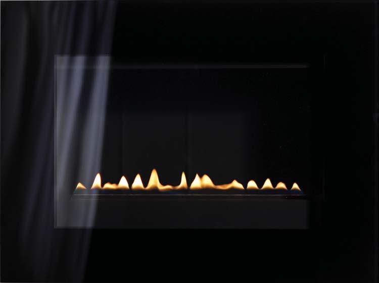
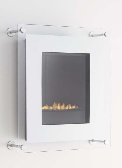
2 P23 Contemporary glass L23 Black
3 INSTALLATION INSTRUCTIONS Preliminary Notes Before Installation This appliance is a high efficiency, flueless, flame effect gas fire. It provides radiant and convected warmth both efficiently and safely utilising the latest type catalytic convertor burner technology. The appliance incorporates a combustion monitoring system (Oxygen Depletion System). It must not be adjusted or put out of operation. If replaced then manufacturers original parts must be used. The appliance is designed to fit various types of situations as listed in the Installation Requirements. This appliance must be installed in accordance with the rules in force and only used in a sufficiently ventilated space. A minimum of 100cm 2 (15.5in 2 ) purpose provided ventilation is required for this appliance. An openable window or louvre is also required. This appliance is factory set for operation on the gas type, and at the pressure stated on the appliance data plate. The room size should be a minimum of 23m 3 (812ft 3 ) to allow adequate circulation of air and ensure the correct operation of the fire. This volume may include adjacent spaces but these spaces must not be separated by a door. In order to convert from cubic feet (ft 3 ) to cubic metres (m 3 ) divide the room volume (in ft 3 ) by This appliance is intended as a secondary source of heat only and should not be used in a room without some form of background heating present. The appliance must not be installed in a bedroom, bathroom or any sleeping area. The appliance does not require a flue system of any type as the catalytic converter cleans the flue products to provide a complete combustion system, which is intrinsically safe. The appliance must be installed by a competent person in accordance with Gas Safety (Installation and Use) Regulations 1998 or rules in force. It is strongly recommended that a CORGI registered engineer is used for this purpose, as they are the only persons approved by the HSE under the above regulations. On initial lightup of a new appliance, the newness will burn off within the first few hours of operation. During this period some smoke may be emitted from outlet grille, this should be no cause for concern. Accordingly, the room should be well ventilated with all windows and doors open during this period. Read all these instructions before commencing installation.
4 Section Contents Page No. 1.0 Important Notes Appliance Data Installation Requirements Room Sizing Site Requirements Ventilation Unpacking the Appliance Component Checklist Gas Supply Routes Fixing the Appliance Checking the Burner 5 Section Contents Page No. 8.0 Testing and Commissioning Operating the Appliance Spark Failure Setting pressure Fitting the Decorative Frame Briefing the customer Servicing Servicing the Burner Unit Pilot Assembly Catalyst Testing for Firebox Leakage Troubleshooting Guide 10 User Instructions 1.0 IMPORTANT NOTES This appliance is a catalytic flueless flame effect gas fire, providing radiant and convected warmth. It is designed to operate on Natural Gas following factory set adjustments, (see Data Plate on appliance for gas type and pressure). It is the LAW that all gas appliances and fittings are installed by a competent person (such as a CORGI registered fitter) and in accordance with the Gas Safety (Installation and Use) Regulations 1998, the relevant British Standards for Installation, Codes of Practice and the Manufacturers' Instructions. The installation shall also be carried out in accordance with the following regulations: The Building Regulations issued by the Department of the Environment, the Building Standards (Scotland) (Consolidation) Regulations issued by the Scottish Development Department. Relevant British standards insofar as the relevant areas are not covered by these instructions. Note: For Republic of Ireland, reference should be made to the relevant standards governing installation. (IS 813: 1996) Failure to comply with these regulations could lead to prosecution and deem the warranty invalid. This appliance must be installed in accordance with the rules in force and used only in a sufficiently ventilated space. A minimum of 100cm 2 (15.5 in 2 ) purpose provided ventilation is required for this appliance, an openable window or louvre is also required. To reduce the possibility of draughts entering the room via the air vent, we recommend the use of "Black Hole" or "Vortex" type vents featuring internal baffles. It should be noted that heaters create warm air currents. These currents move heat to wall surfaces next to the heater. Installing the heater next to vinyl or cloth wall coverings or operating the heater where impurities in the air (such as tobacco smoke) exist, may discolour walls. Consult ALL instructions before installation and use of this appliance. This appliance is free from any asbestos material. 1
5 APPLIANCE DATA L23 Models P23 Models Gas Group G20 Natural Gas CAT I2H G20 Natural Gas CAT I2H Inlet Pressure 20 mbar (+/- 2.0mbar) 20 mbar (+/- 2.0mbar) Max Energy Input Gross 2.0 kw Gross 2.0 kw Net 1.8 kw Net 1.8 kw Max Gas Rate 0.20 m3/h 0.20 m3/h Min Energy Input Gross 1.3 kw Gross 1.0 kw Net 1.15 kw Net 0.9 kw Pilot Energy Input Gross 166 W Gross 166 W Net 150 W Net 150 W Burner Pressure High 18.7 mbar. (+/-1.5 mbar). Hot 18.7 mbar. (+/-1.5 mbar). Hot 18.6 mbar. (+/-1.5 mbar). Cold 18.6 mbar. (+/-1.5 mbar). Cold Low 7.4 mbar. (+/-0.75 mbar). Hot 4.1 mbar. (+/-0.75 mbar). Hot 7.3 mbar (+/-0.75 mbar). Cold 4.0 mbar (+/-0.75 mbar). Cold Main burner flow restrictor Stereo 1.03mm (1/4 BSP) Stereo 1.03mm (1/4 BSP) Oxypilot SIT/Bray 9082 SIT/Bray 9082 Gas Inlet Connection 8mm inlet restrictor elbow 8mm inlet restrictor elbow Ignition Piezo spark Piezo spark Spark Gap 4.0 mm (± 1.0mm) 4.0 mm (± 1.0mm) Please see Data Badge affixed to appliance for current data. This appliance is for use only with the gas type, and at the pressure stated on the appliance Data Badge. INSTALLATION REQUIREMENTS If the appliance is to be sited near a disused natural draught flue it is recommended that the old flue should be partially sealed off to prevent draughts, however some ventilation will be required to prevent condensation. The appliance is designed to be wall mounted. It is possible to install the appliance onto certain types of combustible materials - see section entitled Clearances to combustible materials. In the event that the fire is sited near a disused or unserviceable fireplace served by a natural draught flue, any existing under grate draught device should be sealed off to prevent loss of heat or creation of draughts. The passageway into the flue should be partially sealed to prevent excessive draughts, however some ventilation will be required in the old flue to prevent condensation and dampness. Advice should be sought from your local building control officer. ROOM SIZING All Models : The room size should be a minimum of 23m 3 (e.g x 10 1 x 8 ) to allow adequate circulation of air and ensure the correct operation of the fire. This volume may include adjacent spaces but these spaces must not be separated by a door. To calculate a room size in cubic metres (m 3 ) divide the room volume in cubic feet (ft 3 ) by SITE REQUIREMENTS This appliance is designed to be wall-hung. Do not recess any part of the appliance into the wall. This Appliance may be installed in any room in a home except bedrooms and bathrooms. Installation in living rooms is common, however other rooms such as kitchens, dining rooms and hallways are permitted, providing a suitable natural gas supply is available, and rooms sizing and ventilation requirements are strictly adhered to (see section 4.1). The appliance is designed to be versatile, and as such will operate correctly when exposed to normal gentle draughts experienced within the home. It is not recommended, however that the appliance be installed in areas where it is likely to be exposed to persistent strong draughts, that may be generated by outside doors or windows, air vents etc. It is recommended that the appliance should not be installed within one metre of any air vent. 2
6 4.0 SITE REQUIREMENTS (continued) Clearances to non-combustibles Non combustible surfaces are defined as brick, metal, marble, concrete etc. and also a number of man-made materials impervious to flame. If in doubt refer to the material manufacturer for further information before proceeding with installation. Clearances to the sides of the appliance are 100mm (4in). Clearance to the front of the appliance is 500mm (20in). The back of the appliance may be installed directly onto a non-combustible wall, providing the area behind the appliance is flat and does not interfere with the various vent holes in the back panel of the appliance. A non combustible shelf of any depth may be positioned above the appliance provided it is no closer than 400mm from the top of the appliance glass panel and the wall above the appliance is non combustible. The appliance must not be positioned vertically within 60mm (2.4in) of a solid floor (i.e. wood or stone) or hearth. This dimension is measured vertically to the bottom of the appliance firebox. Clearances to combustible materials Combustible materials are defined as wood, fabrics, or other materials likely to combust if exposed to flame. Generally, any material, which is likely to discolour, melt or misshape when exposed to moderate heat, should be considered as a combustible material or surface. Clearance to the sides of the appliance are 100mm (4in) but curtains, drapes and other fabrics are not permitted within a distance of 500mm (20in) of the appliance sides. No such materials are permitted directly above the appliance regardless of distance. The minimum clearance to the ceiling above the appliance is 800mm (31.5in) measured from the top of the appliance inner glass panel. Combustible materials should not be positioned directly in front of the appliance within a distance of one metre. Under no circumstances should any electrical equipment e.g. plasma screen TV sets etc. be positioned on the wall above the appliance. The appliance is designed to be wall mounted alone and not in conjunction with any type of combustible fire surround. No combustible shelves should be positioned on the wall above the appliance. It should be established that any mirrors or picture frames etc. to be positioned on the wall above the appliance are able to withstand prolonged exposure to moderate heat and moisture before proceeding with their installation. The back of the appliance may be installed directly onto a combustible wall, providing it is relatively flat and does not interfere with the various vent holes in the back panel of the appliance. The wall must be structurally sound and constructed from a material capable of withstanding moderate heat. Finished plaster, conventional wall paper and dry-lined plasterboard are examples of suitable materials. Materials such as flock, blown vinyl and embossed paper which are sensitive to even small amounts of heat should be avoided as scorching and or discolouration may occur over time. If the appliance is to be mounted on a dry lined wall or a timber framed construction wall then the integrity and ability of the wall to carry the weight of the appliance must be confirmed. It is important in these circumstances that any vapour control barrier is not damaged, and that any structural members of the house frame are not damaged. 4.1 The appliance must not be positioned vertically within 100 mm (4in) of a carpeted floor, rugs or fabric materials of any kind. This dimension is measured vertically to the bottom of the appliance firebox. VENTILATION A minimum of 100 cm 2 purpose provided ventilation is required for this appliance. This may be achieved either with one vent 100 cm 2 at a high or low position in the room, or split ventilation i.e. 50cm 2 be installed at high level and 50cm 2 be installed at low level within the room. An openable window or equivalent is also required. The requirements of other flued appliance operating in the same room or space must be taken into consideration when assessing ventilation. 3
7 VENTILATION (continued) Any ventilation fitted must comply with BS 5871 part 4 and BS 5440 part 2. Ventilation fitted under, or within immediate vicinity of the appliance must not be used as it may adversely effect performance of the ODS system. The appliance MUST NOT be installed in a bedroom, bathroom or any sleeping area. For Republic of Ireland, see relevant rules in force. The appliance should not be installed within one metre of any air vent. UNPACKING THE APPLIANCE Remove the outer packaging, remove any instructions or fixing kits. Read ALL these instructions before continuing to unpack or install this appliance. Lift off the remaining packaging components and remove the contents of the box. Check that the components supplied correlate with the component checklist. Please dispose of all the packaging materials at your local recycling centre. COMPONENT CHECKLIST QUANTITY DESCRIPTION 1 Firebox and burner assembly 1 Set of manufacturers instructions 1 Decorative black glass facia assembly (L23 models) 1 Decorative silver glass facia panel (P23 models) 4 Decotaive metal corner columns (P23 models) 1 Screw and wall plug pack 1 Rubber grommet 1 Fitting template 6.0 GAS SUPPLY ROUTES There are four possible entry points for the gas supply pipework to enter the appliance firebox. These entry points are knock out type holes. Non-concealed gas connections may be made using the entry points at either end of the firebox or the one in the bottom of the firebox. A concealed gas connection may be made using the knock out hole in the centre back of the firebox. Select the most appropriate entry point and knock out the relevant hole No more than 1.5m of 8mm diameter pipe must be used to avoid unnecessary pressure drops. If a concealed gas connection is to be made, the supply pipe should always be sleeved through walls and floors using the shortest possible route. For concealed supply pipe routing, pipes must (where possible) be vertical and providing there is sufficient wall thickness available, they should be placed in pipe chases. Horizontal pipe runs should be avoided. Prior to chasing a solid wall, an inspection should be made to note the proximity of any cables/sockets outlets which may already be buried. Pipes must be secured using suitable clips and protected against corrosion. Ideally factory finished protected pipework and fittings should be used. Joints should be kept to a minimum and compression fittings must not be used. The pipework installation must be tested for soundness before any protection is applied and/or the pipework and fittings are buried. 4


8 7.0 FIXING THE APPLIANCE After having selected the final mounting position of the appliance, taking into account the site requirements as specified in section 4 of these instructions, the integrity of the wall, and the feasibility of the proposed supply pipe routing, the firebox of appliance may be secured to the wall. A fitting template is supplied to assist with this. For L23 models : Mark the positions shown as Gas model L23G on the wall. For P23 models : Mark the positions shown as Gas model P23G on the wall. If the appliance is to be mounted on the inner leaf of a conventional cavity wall, or a solid wall, drill four holes to a depth of 42mm using a 8mm masonry bit. Insert the wallplugs provided. If the appliance is to be mounted on a dry lined wall or a timber framed construction wall then special cavity screw fixings will be required which are not supplied with this product. These should be constructed from metal and not plastic. If a concealed gas connection is to be made ensure the gas supply pipe is in it s final position and can enter the appliance in the correct position when the appliance is hung on the wall. Insert the wall fixing screws into the top wall plugs, taking care to leave the screws protruding approximately 5mm from the wall. Now hang the appliance onto these screws through the two keyhole shaped holes in the back panel of the appliance. Insert the lower fixing screws into the lower wall plugs through the corresponding fixing holes in the lower part of the back panel. Do not tighten fully. Before tightening the wall mounting screws fully, at this stage it is recommended to check the horizontal alignment of the appliance with a spirit level, as small adjustments can still be made if necessary. When this has been checked, tighten all four fixing screws fully. To access the upper fixing screws insert a screwdriver either through the round holes in the front of the outlet grille, or alternatively for easier access the outlet grille may be removed and the fixing screws accessed more directly through the holes in the deflector baffle as shown above. 7.1 CHECKING THE BURNER There are no imitation fuel bed components to install. The appliance features a ribbon burner which is designed to produce a continuous band of flame over it s length. The burner should be visually inspected to ensure it is free from any foreign matter. If it is necessary to clean or dust off the burner then the glass door should be removed by removal of the four retaining screws. Re-fit the glass door after cleaning or inspection, ensuring a good seal. 5

9 TESTING AND COMMISSIONING Turn on and test the gas supply up to the fire for any leaks, in accordance with the current edition of BS6891. OPERATING THE APPLIANCE The pilot is visible behind the left hand side of the burner. The control knob is located on the lower right hand side of the outer case. It is of a spherical design and is marked as shown in the diagram to the right; Push in and turn the control knob to the SPARK position, and hold there for a few seconds. Continue turning anti-clockwise through the spark click to the PILOT light position, ensuring the pilot has lit. If not, return the knob clockwise, and repeat. When the pilot lights after the spark, keep the knob depressed for approximately ten seconds. Now release the knob and the pilot should stay alight. If the pilot is extinguished during use, wait three minutes before repeating the ignition procedure. OFF position SPARK position LOW position HIGH position To achieve the HIGH setting, push the control knob in slightly and continue turning anti-clockwise to the high position. The main burner should light after a few seconds. To decrease the setting to LOW, turn the control knob clockwise to the low setting. To turn to the PILOT position from the HIGH or LOW positions, press the control knob in, and return to the pilot position and release. To turn the fire OFF, keep the knob pressed in, return to the off position and release SPARK FAILURE The gap between the spark electrode and the pilot should be 3-5mm to produce a good spark. There should be no need to adjust this. If under any circumstances the piezo electric spark fails, the pilot cannot be lit manually. SETTING PRESSURE The pressure test point is located on the left hand side of the appliance, on the main burner pipe, next to the brass restrictor/connector. Release the setting pressure test point screw, and attach a U gauge. Light the fire on the HIGH setting. To commission the appliance, the burner pressure must be in accordance with the figures stated in the data section of these instructions. The fire is factory set to achieve these pressures and any significant variation could indicate a supply problem. If the pressure is too high, the gas supply meter may be set incorrectly. This should be checked with the fire running and if necessary reset by the gas supplier. If the burner pressure is too low, then check the inlet pressure with the appliance running. If this is less than approximately 20mbar it will need to be reset by the gas supplier. If the setting pressure is too low, but the meter pressure is acceptable, then a problem in the supply pipework is to be suspected. This will be dirt and debris, kinked or inadequate size pipes, restriction in a fitting, shut off elbow not fully open or solder flashing across a joint. Identify the cause of the restriction and rectify. Switch the fire off, disconnect the U gauge and refit the test nipple screw. Light the fire and check for gas soundness. In the event that the burner pressure is not in accordance with the figures stated in the data section of these instructions, the appliance must not be commissioned, and the manufacturer should be contacted for guidance. 6
10 8.4 FITTING THE DECORATIVE FRAME ASSEMBLY P23 models : The appliance is supplied with a selection of differently couloured decorative frames. Remove the chosen decorative frame assembly from any protective packaging, and remove any protective film that may be present on the frame. The frame is hung onto the firebox via the two upper hanging brackets and then secured to the firebox via the two lower knurled fixing bolts, which are inserted through the holes in the lower frame mounting brackets after the frame is in position. See diagrams to the right and below. P23 models L23 and P23 models: Remove the glass facia panel from any protective packaging. The glass facia panel is supported by four M6 screws which protrude from the front of the outer casing. Ensure each screw is unscrewed approximately one turn from the fully screwed in position in order to create a 2mm gap (shown). Simply hang the facia panel onto the outer casing ensuring that the corresponding keyhole shaped holes engage the screwheads fully. P23 models: To fit the decorative corner columns, ensure the main glass facia is mounted in position. Remove any transit tape and unscrew the front clamping disc and remove. L23 models Front clamping disc Compress the assembly Compress the column assembly and position behind the glass panel, lining up with the appropriate hole. Release the assembly when in position and secure in place by refitting the front clamping disc. 7
11 9.0 BRIEFING THE CUSTOMER All instructions must be handed to the user for safekeeping. Show the customer how to light and control the fire. After commissioning the appliance, the customer should be instructed on the safe use of the appliance and the need for regular servicing. Frequency of service depends on usage, but MUST be carried out at least once annually. Advise that cleaning of the fire maybe achieved when the fire is cold using a damp cloth and mild detergent on most surfaces. Advise that the fire will emit a "newness" smell for a time after initial commissioning and that extra ventilation may be needed during this time. Recommend that a guard be used for the protection of the young, pets, the elderly and the infirm 10.0 SERVICING Isolate the fire from the gas supply. Ensure that the fire is fully cold before attempting service. A suggested procedure for servicing is detailed below. 1. Lay out the dustsheet and tools. 2. Remove the decorative frame/glass facia assembly. Removal is reverse of section Remove the glass door assembly (4 screws) and clean carefully. 4. Inspect the burner and the catalyst and clean if necessary with a soft brush. 5. Disconnect the gas supply. 6. Detach the burner front cover plate by removal of the four retaining screws. Undo the four screws retaining the burner support brackets to the base and rear of the firebox. Remove the control knob and spindle assembly from the valve by removal of the spindle retaining clip. 7. Remove the burner unit, strip off the burner pipes and clean thoroughly. 8. Clean the in-line restrictor, pilot assembly and the burner tube. Do not attempt to remove the pilot injector as this can cause damage. 9. Re-assemble components. 10. Turn on the gas supply and leak test. Check pilot and burner for good ignition. 11. Refit the glass door assembly, ensuring correct orientation and a good seal. 12. Refit the decorative facia/frame assembly as detailed in section Check the purpose provided ventilation is un-obstructed. 14. Light the fire and test setting pressures. 15. Check safe operation of the appliance For specific servicing instructions, see relevant sections. SERVICING THE BURNER UNIT AND GAS ASSEMBLY Firstly, remove the decorative glass facia assembly as described in section 8.4. Remove the inner glass panel, and disconnect the gas connection inside appliance. The gas connections to the gas valve can now be released. Detach the burner front cover plate by removal of the four retaining screws. Undo the four screws retaining the burner support brackets to the base and rear of the firebox, and remove the control knob and spindle assembly by removal of the spindle retaining clip. The burner may now be removed. Remove the pilot and main burner pipes and blow through to dislodge any debris. Now remove the restrictor elbow and blow through to make sure it is entirely clear. Unclip the pilot lint gauze and clean with a soft brush. Clean the exterior of the pilot assembly with a soft brush and blow through the flame ports on the pilot head. Check the aeration holes are free from lint or dirt. The pilot assembly can be removed if required by disconnecting the electrode HT lead, gas pipe and unscrewing the mounting screws and lifting away. The pilot assembly is a non-serviceable item and should not be taken apart. Aeration holes must be absolutely clear internally for proper operation. NEVER MODIFY OR BEND THE THERMOCOUPLE TO MAKE THE PILOT STAY ALIGHT. Modifications are dangerous and can have serious unseen effects on safety. If the pilot will not stay lit there is a problem with dirt, the gas supply to it, or the thermocouple needs replacement. The gas valve is a non-serviceable item. If this needs replacement, remove M4 securing screw holding the valve in place, remove all pipe unions, electrode lead, thermocouple lead and then the complete valve. Replacement must be original manufacturers parts. Re-assembly is the reverse of removal. Ensure setting pressures are as stated in Section 2; Appliance Data. 8
12 10.2 PILOT ASSEMBLY Clean the pilot assembly with a soft brush and blow through. Check the aeration holes are free of any dirt or lint. Clean thoroughly internally, the connection can be removed from the base of the pilot unit using two spanners to make cleaning easier. Do not damage or try to dismantle the pilot injector. The unit is factory set and the only check necessary is to ensure the spark gap is correct. See specifications for gas setting. NEVER MODIFY OR BEND THE THERMOCOUPLE TO MAKE THE PILOT STAY ALIGHT. If the pilot will not stay lit there is a problem with dirt, the gas supply, or the thermocouple needs replacement. Modifications are dangerous and can have a serious unseen effect on safety and therefore MUST not be done. Replacements must be original manufacturers parts. Re-assemble in the reverse of removal. Ensure setting pressures are as stated in Section 2; Appliance Data CATALYST It is recommended that the catalysts are inspected for signs of damage and dirt during routine servicing procedures. The expected life of the catalysts is in excess of 11,000 hours (10 years of normal use). After this time the catalysts should be replaced. If there are any deposits of dirt or soot on the catalyst they should be cleaned with a soft brush and a vacuum cleaner. If removed for cleaning ensure the seals are in good condition before replacing the catalyst. New seals will usually be required. The performance of the catalysts may be checked using a combustion gas analyser as follows. Any analyser used should conform to EN Ignite the fire as per the operating instructions, and run at maximum setting for 15 minutes. Position gas sample probe directly over the catalysts via the outlet grille, on top of the appliance. Record the carbon dioxide (CO2) concentration and then the carbon monoxide (CO) concentration as displayed by the analyser - also noting the units in which the values are expressed. Most analysers display carbon dioxide (CO2) concentrations in percentage (%) terms and carbon monoxide concentration in parts per million (ppm) terms. In order to calculate the combustion ratio for the appliance (CO/CO2) it is first necessary to express both gas concentrations in terms of percentage. To convert from parts per million (ppm) to a percentage (%) divide the ppm figure by 10,000. Examples : 35ppm = %, 15ppm = %, 5ppm = %. Now divide the concentration of carbon monoxide (CO) expressed in percent by the concentration of carbon dioxide (CO2) to obtain the appliance combustion ratio. CO (%) CO2 (%) = ratio The combustion ratio of the gasses emitted by the catalytic convertor should not exceed If replacing, firstly, remove the decorative frame/glass facia as described in section 8.4. The catalysts are located on the top of the internal firebox and can be removed be unscrewing the retaining nuts securing the clamping plates. Remove the catalysts their seals and discard. Refit the new catalysts and seals in reverse order, ensure the catalysts and the glass door have good seals TESTING FOR FIREBOX LEAKAGE Appliances that are several years old or have been extensively dismantled should be checked for soundness. It is important that all the products of combustion pass through the catalytic converter at the top of the firebox before leaving the appliance. The firebox is heated by lighting for a few minutes to provide a flow through the firebox. The burner is then shut off and a smoke pellet or match introduced at the base of the fire underneath the burner tray. Large quantities of smoke will emerge from the top of the appliance, but none should emerge from the joints or gasket faces, especially around the door. It is important to note that the appliance can never be expected to be 100% smoke tight and small quantities of smoke may be seen in corners of joints and gasket faces etc without affecting safety when the fire is in operation. 9
13 11.0 TROUBLESHOOTING GUIDE Fire sparks but pilot does not light Pilot lights but then goes out Fire does not spark at pilot Fire runs for a time and then cuts off Pilot flame shrinks when fire is on high Fire smells when first lit or in use No gas to fire, check isolators are open. Pipe work blockage, clean out. Air not fully purged, re purge supply or wait longer. Spark earthing to metal work, reset gap correctly. Blocked pilot, clean out internally. Severe restriction in gas supply: clear obstruction. Faulty thermocouple, replace pilot unit. Blocked pilot, clean out. Blocked lint gauze, clean. Hold control knob in for longer. Check control knob does not foul indicator plate. If the pilot will not stay lit there is a problem with dirt, the gas supply, or the thermocouple needs replacement. Modifications are dangerous and can have a serious unseen effect on safety. NEVER MODIFY OR BEND THE THERMOCOUPLE TO MAKE THE PILOT STAY ALIGHT. HT lead detached, refit. Check the spark gap (see section 8.2). Faulty piezo unit, replace. Debris shorting out electrode, clean. Spark shorting to metalwork under tray, realign HT lead. Loose or faulty thermocouple, rectify. Blocked pilot, clean out. Dirt or lint in pilot aeration hole or on the lint gauze, clean thoroughly. If the pilot will not stay lit there is a problem with dirt, the gas supply, or the thermocouple needs replacement. Modifications are dangerous and can have a serious unseen effect on safety. NEVER MODIFY OR BEND THE THERMOCOUPLE TO MAKE THE PILOT STAY ALIGHT. Poor gas flow to fire, check pressure with fire on high. If pressure is low, remove any restriction in pipework or valve. Check all isolators are adequately sized and fully open. Check meter pressure is adequate. If the pilot will not stay lit there is a problem with dirt, the gas supply, or the thermocouple needs replacement. Modifications are dangerous and can have a serious unseen effect on safety. NEVER MODIFY OR BEND THE THERMOCOUPLE TO MAKE THE PILOT STAY ALIGHT. Newness smell from brand new appliance. Leakage occurring. Carry out leakage test and rectify any problems. Combustible materials used in incorrect positions. 10
14 USER INSTRUCTIONS Section Content Page No 1.0 Important Notes Clearances to Combustibles Ventilation & Room Size Operating Instructions Combustion Monitoring System Cleaning Servicing List of Replacement Parts IMPORTANT NOTES The installation and Servicing of this fire MUST only be carried out by a competent person (such as a CORGI registered fitter) in accordance with the Gas Safety (Installation and Use) Regulations 1998, the relevant British Standards, Codes of Practice, the Building Regulations and the manufacturer's instructions. Failure to comply with the above recommendations could lead to prosecution and invalidate the appliance warranty. Always keep a note of the installer's name and address, CORGI registration number, the original purchase receipt and the date of installation for future reference. Failure to produce these documents may invalidate the warranty. The appliance should be serviced regularly to ensure continued safe operation. See the servicing section for further reference. Parts of this appliance become naturally hot during use. It is recommended that a suitable fireguard conforming to BS 8423 : 2002 is used, especially where young children, pets, the elderly or infirm are concerned. The manufacturer of this appliance considers all surfaces as working surfaces with the exception of the control knob and indicator bracket. Combustible items, such as flooring and furniture and soft wall coverings (such as blown vinyl or embossed paper), low temperature surrounds etc may discolour if fitted too close to the fire. See relevant section for further details on clearances to combustibles. No combustible materials or flooring should protrude onto the hearth (if fitted). This appliance incorporates a combustion monitoring system (ODS). DO NOT burn any foreign material on this fire. Under no circumstances shall the appliance be used if the glass front door or panel has been removed, damaged or is open. DO NOT place any objects on top of the appliance, or cover the outlet grille in any way. DO NOT operate the appliance with any parts removed or missing. The integral catalysts should be checked by the installer upon servicing to ensure there are no defects or obstructions that may prevent the satisfactory flow of combustion products. The expected life of the catalyst is in excess of 11,000 hours (10 years of normal use). After this time the catalyst should be replaced. This appliance is only suitable for the gas type for which it is supplied. It should be noted that heaters create warm air currents. These currents move heat to wall surfaces next to the heater. Installing the heater next to vinyl or cloth wall coverings or operating the heater where impurities in the air (such as tobacco smoke) exist, may discolour walls. WARNING: Due to the nature of this product the area around the top of the appliance (i.e. the grille) gets very hot. Care should be taken when operating the appliance. 1
15 2.0 CLEARANCES TO COMBUSTIBLES Clearances to combustible materials Combustible materials are defined as wood, fabrics, or other materials likely to combust if exposed to flame. Generally, any material, which is likely to discolour, melt or misshape when exposed to moderate heat, should be considered as a combustible material or surface. Clearance to the sides of the appliance are 100mm(4in) but curtains, drapes and other fabrics are not permitted within a distance of 500mm(20in) of the appliance sides. No such materials are permitted directly above the appliance regardless of distance. The minimum clearance to the ceiling above the appliance is 800mm measured from the top of the appliance glass panel. Combustible materials should not be positioned directly in front of the appliance within a distance of one metre. Under no circumstances should any electrical equipment e.g. plasma screen TV sets etc. be positioned on the wall above the appliance. The appliance is designed to be wall mounted alone and not in conjunction with any type of combustible fire surround. No combustible shelves should be positioned on the wall above the appliance. It should be established that any mirrors or picture frames etc. to be positioned on the wall above the appliance are able to withstand prolonged moderate heat before proceeding with their installation. The back of the appliance may be installed directly onto a combustible wall, providing it is relatively flat and does not interfere with the various vent holes in the back panel of the appliance. The wall must be structurally sound and constructed from a material capable of withstanding moderate heat. Finished plaster, conventional wall paper and dry-lined plasterboard are examples of suitable materials. Materials such as flock, blown vinyl and embossed paper which are sensitive to even small amounts of heat should be avoided as scorching and or discolouration may occur over time. The appliance must not be positioned vertically within 100 mm of a carpeted floor, rugs or fabric materials of any kind. This dimension is measured vertically to the bottom of the appliance firebox. Clearances to non-combustibles Non combustible surfaces are defined as brick, metal, marble, concrete etc. and also a number of man-made materials impervious to flame. If in doubt refer to the material manufacturer for further information before proceeding with installation. Clearances to the sides of the appliance are 100mm (4in). Clearance to the front of the appliance is 500mm (20in). The back of the appliance may be installed directly onto a non-combustible wall, providing it is relatively flat and does not interfere with the various vent holes in the back panel of the appliance. A non combustible shelf of any depth may be positioned above the appliance provided it is no closer than 400mm from the top of the appliance glass panel and the wall above the appliance is non combustible. The appliance must not be positioned vertically within 60mm of a solid floor (i.e. wood or stone) or hearth. This dimension is measured vertically to the bottom of the appliance firebox. 3.0 VENTILATION AND ROOM SIZE Purpose provided ventilation of 100cm 2 is required for this appliance. An openable window or equivalent is also required. The appliance should not be installed within 500mm of any air vent. Any ventilation fitted must comply with BS 5871 part 4 and BS 5440 part 2. Ventilation fitted under, or within immediate vicinity of the appliance must not be used as it may adversely effect performance of the combustion monitoring system (ODS) system. The requirements of other appliances operating in the space or room must be taken into consideration when assessing ventilation requirements, this will have been carried out by your CORGI registered installer. A supply of fresh air into the room is advisable to maintain temperatures within limits. The appliance MUST NOT be installed in a bedroom or bathroom. For Republic of Ireland, see relevant rules in force. 2
16 VENTILATION AND ROOM SIZE (continued) The room size should be a minimum of 23m 3 (e.g x 10 1 x 8 ) to allow adequate circulation of air and ensure the correct operation of the fire. This volume may include adjacent spaces but these spaces must not be separated by a door. To calculate a room size in cubic metres (m 3 ) divide the room volume in cubic feet (ft 3 ) by This appliance is intended as a secondary source of heat only and should not be used in a room without some form of background heating present. OPERATING INSTRUCTIONS The pilot is visible behind the left hand side of the burner. The control knob is located on the lower right hand side of the outer case. It is of a spherical design and is marked as shown in the diagram to the OFF position right. Push in and turn the control knob to the SPARK position, and hold there for a few seconds. Continue turning anti-clockwise through the spark click to the PILOT light position, ensuring the pilot has lit. If not, return the knob clockwise, and repeat. When the pilot lights after the spark, keep the knob depressed for approximately ten seconds. Now release the knob and the pilot should stay alight. If the pilot is extinguished during use, wait three minutes before repeating the ignition procedure. SPARK position LOW position HIGH position To achieve the HIGH setting, push the control knob in slightly and continue turning anti-clockwise to the high position. The main burner should light after a few seconds. To decrease the setting to LOW, turn the control knob clockwise to the low setting To turn to the PILOT position from the HIGH or LOW positions, press the control knob in, and return to the pilot position and release. To turn the fire OFF, keep the knob pressed in, return to the off position and release. COMBUSTION MONITORING SYSTEM This fire is fitted with a combustion monitoring safety device (ODS). If the appliance shuts down during use for no apparent reason then several reasons may be suspected. If a door or window has been opened creating a draught, then pilot disturbance could be the problem and removal of the draught should resolve this. The appliance can then be re-lit in accordance with the previous section. If pilot disturbance is not the cause, then the ODS safety system may be in operation. Switch the appliance OFF, call in your installer to check the appliance and ventilation. Remedial work must be carried out as required. DO NOT allow the appliance to be used until the appliance and installation is passed as safe. If the pilot continues to be extinguished, you must call your installer to check the operation of the complete appliance. CLEANING Before carrying out any of the following operations, ensure that the appliance is OFF and completely cold. INNER GLASS PANEL - This can be cleaned with a suitable glass cleaner, or propriety ceramic hob cleaner. Test on a small area first. GLASS FACIA PANEL - This should only be cleaned using a suitable glass cleaner. Test on a small area first. PAINTED AREAS - These can be cleaned using a dry cloth. SERVICING The appliance should be checked on an annual basis to ensure it is working safely. The frequency of service will depend on usage, but MUST be carried out at least once annually. Servicing must be carried out by a competent person, such as a CORGI registered installer. The Installation instructions carry full servicing details for the use of the installer. LIST OF SPARE PARTS PART NO. ITEM PART NO. ITEM F Glass door assembly F Pilot assembly FT003155/1 Gas valve TRAY055 Burner tray F Catalyst F Seal kit for Catalyst As our policy is one of continuous improvement and development, we hope therefore you will understand we must retain the right to amend details and/or specifications without prior notice. 3 F860591
PLATINUM FIRES. Revision A - 10/05 Country(s) of destination - GB/IE
 of destination - GB/IE") PLATINUM FIRES ADEN ALITA ALVA FLUELESS GAS FIRE INSTALLATION AND USER INSTRUCTIONS All instructions must be handed to user for safekeeping Revision A - 10/05 Country(s) of destination - GB/IE Platinum
PLATINUM FIRES ADEN ALITA ALVA FLUELESS GAS FIRE INSTALLATION AND USER INSTRUCTIONS All instructions must be handed to user for safekeeping Revision A - 10/05 Country(s) of destination - GB/IE Platinum
PLASMA CAPELLA PLATINUM
 PLASMA CAPELLA PLATINUM FLUELESS GAS FIRE INSTALLATION AND USER INSTRUCTIONS All instructions must be handed to user for safekeeping Revision C - 08/08 Country(s) of destination - GB/IE Focal Point Fires
STONE CONTEMPORARY GLASS
 STONE LIMESTONE - GRANITE CONTEMPORARY GLASS FLUELESS GAS FIRE INSTALLATION AND USER INSTRUCTIONS All instructions must be handed to user for safekeeping Revision A - 06/08 Country(s) of destination -
INSTALLATION & USER INSTRUCTIONS WALL MOUNTED HIGH EFFICIENCY GAS FIRE
 INSTALLATION & USER INSTRUCTIONS WALL MOUNTED HIGH EFFICIENCY GAS FIRE MODELS COVERED BY THESE INSTRUCTIONS Focal Point Fires plc. Christchurch, Dorset BH23 2BT Tel: 01202 499330 Fax: 01202 499326 www.focalpointfires.co.uk
installation and user instructions
 installation and user instructions All instructions must be handed to user for safekeeping Revision A - 06/09 Country(s) of destination - GB/IE eko 5010 eko 5020 eko 5030 eko 5040 fuel effect gas fire
INSTALLATION & USER INSTRUCTIONS
 INSTALLATION & USER INSTRUCTIONS WALL MOUNTED HIGH EFFICIENCY GAS FIRE Christchurch, Dorset BH23 2BT Tel: 01202 588 638 Fax: 01202 499 639 www.ekofires.co.uk e-mail: sales@ekofires.co.uk MODELS COVERED
AFINA FLUELESS GAS STOVE INSTALLATION AND USER INSTRUCTIONS
 AFINA FLUELESS GAS STOVE INSTALLATION AND USER INSTRUCTIONS All instructions must be handed to user for safekeeping Revision A - 08/05 Country(s) of destination - GB/IE CK Fires Ltd. 1 Stour House, Clifford
NOVO HIGH EFFICIENCY GAS FIRE MODELS : P23G, L23G. All instructions must be handed to user for safekeeping
 NOVO HIGH EFFICIENCY GAS FIRE MODELS : P23G, L23G All instructions must be handed to user for safekeeping Revision E - 01/13 Country(s) of destination - GB/IE Pure Glow Limited Stourvale Road Lye Stourbridge
MUSE MODEL : P23 WALL MOUNTED FLUELESS GAS FIRE
 MUSE MODEL : P23 WALL MOUNTED FLUELESS GAS FIRE INSTALLATION INSTRUCTIONS It is the LAW that all gas appliances and fittings are installed by a competent person (such as a CORGI registered fitter) and
INSTALLATION & USER INSTRUCTIONS
 INSTALLATION & USER INSTRUCTIONS WALL MOUNTED HIGH EFFICIENCY GAS FIRE MODELS COVERED BY THESE INSTRUCTIONS 5090 GAS FIRE GB IE Christchurch, Dorset BH23 2BT Tel: 01202 588 638 Fax: 01202 499 639 www.ekofires.co.uk
installation and user instructions
 installation and user instructions All instructions must be handed to user for safekeeping Revision B - 08/11 Country(s) of destination - GB/IE eko 5510 eko 5520 eko 5530 high efficiency flueless gas fire
INSTALLATION & USER INSTRUCTIONS
 INSTALLATION & USER INSTRUCTIONS HIGH EFFICIENCY GAS STOVE MODELS COVERED BY THESE INSTRUCTIONS LEIRVIK FLUELESS STOVE DALVIK FLUELESS STOVE Focal Point Fires plc. Christchurch, Dorset BH23 2BT Tel: 01202
INSTALLATION & USER INSTRUCTIONS INSET DECORATIVE GAS FIRE
 INSTALLATION & USER INSTRUCTIONS INSET DECORATIVE GAS FIRE MODELS COVERED BY THESE INSTRUCTIONS HANNINGTON BRASS F500310 HANNINGTON BLACK F500311 Focal Point Fires plc. Christchurch, Dorset BH23 2BT Tel:
INSTALLATION & USER INSTRUCTIONS
 INSTALLATION & USER INSTRUCTIONS INSET FLUELESS GAS FIRE Focal Point Fires plc. Christchurch, Dorset BH23 2BT Tel: 01202 499330 Fax: 01202 499326 www.focalpointfires.co.uk e : sales@focalpointfires.co.uk
Model Apex Falcon, Titan & Zenit
 Model Apex Falcon, Titan & Zenit Installation and User Instructions All instructions must be handed to user for safekeeping This is not a DIY product and must be installed by a Gas Safe registered installer
Wall-mounted Gas Fires. 39 Portrait INSTALLATION,USER & SERVICING INSTRUCTIONS (TO BE LEFT WITH THE CUSTOMER) UK & IRELAND
 UK & IRELAND") Wall-mounted Gas Fires 39 Portrait INSTALLATION,USER & SERVICING INSTRUCTIONS (TO BE LEFT WITH THE CUSTOMER) UK & IRELAND UK IE INSTALLATION INSTRUCTIONS CONTENTS Important Notes Page 2 Commissioning the
Wall-mounted Gas Fires 39 Portrait INSTALLATION,USER & SERVICING INSTRUCTIONS (TO BE LEFT WITH THE CUSTOMER) UK & IRELAND UK IE INSTALLATION INSTRUCTIONS CONTENTS Important Notes Page 2 Commissioning the
NIGMA. Fuel Effect Gas Fire INSTALLATION, SERVICING AND USER INSTRUCTIONS. All instructions must be handed to the user for safekeeping
 Σ NIGMA Fuel Effect Gas Fire INSTALLATION, SERVICING AND USER INSTRUCTIONS All instructions must be handed to the user for safekeeping Revision A 09/03 Country(s) of destination: GB, IE Focal Point Fires
INSTALLATION & USER INSTRUCTIONS
 INSTALLATION & USER INSTRUCTIONS STONE EFFECT DECORATIVE GAS FIRE MODELS COVERED BY THESE INSTRUCTIONS POLARIS GB IE Focal Point Fires plc. Christchurch, Dorset BH23 2BT Tel: 01202 499330 Fax: 01202 499326
installation and user instructions
 installation and user instructions All instructions must be handed to user for safekeeping Revision A - 06/09 Country(s) of destination - GB/IE eko 00 fuel effect gas fire INSTALLATION INSTRUCTIONS Preliminary
installation and user instructions
 installation and user instructions All instructions must be handed to user for safekeeping Revision A - 08/09 Country(s) of destination - GB/IE eko 4010 eko 400 high efficiency fuel effect gas fire Eko
OWNER S GUIDE ETERNITY. MODEL 540C (GC No ) INSET BALANCED FLUE GAS FIRE
 INSET BALANCED FLUE GAS FIRE") 600B637/02 ETERNITY MODEL 540C (GC No. 32-032-19) INSET BALANCED FLUE GAS FIRE THIS APPLIANCE IS FOR USE WITH NATURAL GAS (G20) THIS APPLIANCE IS FOR USE IN THE UNITED KINGDOM (GB) AND THE REPUBLIC OF
600B637/02 ETERNITY MODEL 540C (GC No. 32-032-19) INSET BALANCED FLUE GAS FIRE THIS APPLIANCE IS FOR USE WITH NATURAL GAS (G20) THIS APPLIANCE IS FOR USE IN THE UNITED KINGDOM (GB) AND THE REPUBLIC OF
ULTIMATE INSET LIVE FUEL EFFECT GAS FIRE MODEL 417 OWNER GUIDE
 ULTIMATE INSET LIVE FUEL EFFECT GAS FIRE MODEL 417 OWNER GUIDE THE NATURAL GAS MODEL IS FOR G20 AT A SUPPLY PRESSURE OF 20mbar THE PROPANE GAS MODEL IS FOR G31 AT A SUPPLY PRESSURE OF 37mbar THESE APPLIANCES
INSTALLATION & USER INSTRUCTIONS
 INSTALLATION & USER INSTRUCTIONS INSET DECORATIVE GAS FIRE MODELS COVERED BY THESE INSTRUCTIONS eko 2050 Christchurch, Dorset BH23 2BT Tel: 01202 588 638 Fax: 01202 499 639 www.ekofires.co.uk e-mail: sales@ekofires.co.uk
Versailles. Balanced Flue. Coal Effect Gas Fire INSTALLATION, SERVICING AND USER INSTRUCTIONS
 Versailles Balanced Flue Coal Effect Gas Fire INSTALLATION, SERVICING AND USER INSTRUCTIONS All instructions must be handed to the user for safekeeping Revision A 02/04 Country(s) of destination: GB, IE
Torch framed Installation Guide
 Torch framed 40010567-0602 Installation Guide 1 2 3 4 1 < < < < 5 6 7 > > > > 2 Content 1 Introduction... 1 2 Safety Instructions... 2 3 Installation requirements... 3 3.1 Rear surface construction...
MODEL 466 Radiant / Convector Gas Fire Black Beauty
 I N S T A L L E R G U I D E MODEL 466 Radiant / Convector Gas Fire Black Beauty Please keep in a safe place for future reference 600A734/02 Please leave this Installer Guide with the user This appliance
INSTALLATION INSTRUCTIONS COMPACT GAS STOVE MODEL NUMBER 550
 INSTALLATION INSTRUCTIONS COMPACT GAS STOVE MODEL NUMBER 550 Before installation ensure that the local distribution conditions (identification of the type of gas and pressure) and the adjustment of the
MODEL 466 Radiant / Convector Gas Fire Black Beauty
 O W N E R G U I D E MODEL 466 Radiant / Convector Gas Fire Black Beauty This Owner Guide is intended to help you care for your Valor gas fire. Please read carefully before using your gas fire and keep
INSTALLATION & USER INSTRUCTIONS
 INSTALLATION & USER INSTRUCTIONS CHARMOUTH WALL MOUNTED ELECTRIC FIRE Model shown: Charmouth All instructions must be handed to the user for safekeeping. Revision L - 08/15 1 I N S TA L L AT I O N & U
INSTALLATION & USER INSTRUCTIONS
 INSTALLATION & USER INSTRUCTIONS HIGH EFFICIENCY GAS FIRE MODELS COVERED BY THESE INSTRUCTIONS BLENHEIM HE GAS FIRE HORIZON HE GAS FIRE LULWORTH HE GAS FIRE Focal Point Fires plc. Christchurch, Dorset
OWNER GUIDE. Model 739 OPEN DECORATIVE GAS FIRE. (GC No )
") 5113426/01 OWNER GUIDE Model 739 OPEN DECORATIVE GAS FIRE (GC No. 32-032-54) THIS APPLIANCE IS FOR USE WITH NATURAL GAS (G20). WHEN CONVERTED USING CONVERSION KIT NO. 0595211 THIS APPLIANCE IS FOR USE
5113426/01 OWNER GUIDE Model 739 OPEN DECORATIVE GAS FIRE (GC No. 32-032-54) THIS APPLIANCE IS FOR USE WITH NATURAL GAS (G20). WHEN CONVERTED USING CONVERSION KIT NO. 0595211 THIS APPLIANCE IS FOR USE
INSTALLATION & USER INSTRUCTIONS
 INSTALLATION & USER INSTRUCTIONS WALL MOUNTED ELECTRIC FIRE MODELS COVERED BY THESE INSTRUCTIONS SMEG UK LTD 3a Park Square Milton Park Abingdon OX14 4RN L30 FABEBL L30 FABECR L30 FABERE L30 FABESI L30
Model BR660VA Heat Engine
 5112253/01 Model BR660VA Heat Engine POWER FLUE INSET GAS FIRE (GC No. 32-032-44) THIS APPLIANCE IS FOR USE WITH NATURAL GAS (G20). WHEN CONVERTED USING CONVERSION KIT NO. 0591149 THIS APPLIANCE IS FOR
BLACK KNIGHT 2 - Classic Collection
 BLACK KNIGHT 2 - Classic Collection Installation & Servicing Instructions (GC No. 32 170 16) IMPORTANT - THIS FIRE DOES NOT NORMALLY REQUIRE ADDITIONAL VENTILATION INTO THE ROOM IN WHICH IT IS INSTALLED
INSTALLATION & USER INSTRUCTIONS FULL DEPTH RADIANT/CONVECTOR INSET GAS FIRE
 INSTALLATION & USER INSTRUCTIONS FULL DEPTH RADIANT/CONVECTOR INSET GAS FIRE MODELS COVERED BY THESE INSTRUCTIONS GB IE ELYSEE RADIANT F500007 Focal Point Fires plc. Christchurch, Dorset BH23 2BT Tel:
OWNER S GUIDE MODEL BR417 VA
 600B702/06 OWNER S GUIDE MODEL BR417 VA (G.C.32-032-07) Inset Live Fuel Effect Gas Fire with Ultimate Front AS SUPPLIED, THIS APPLIANCE IS FOR USE WITH NATURAL GAS (G20) WHEN CONVERTED USING VALOR CONVERSION
Installation & Service Instructions
 Part No. 966/9350/1 02 Potterton Housewarmer Illusion ASD - G.C. NO. 37 590 16 966 Inset DGF with ILLUSION FACIA Potterton Housewarmer Stratton ASD - G.C. NO. 37 590 17 966 Inset DGF with STRATTON FACIA
ARIES AURA BLENHEIM STYLE
 ARIES AURA BLENHEIM STYLE FULL DEPTH GAS FIRE INSTALLATION AND USER INSTRUCTIONS All instructions must be handed to user for safekeeping Revision A - 05/05 Country(s) of destination - GB/IE Focal Point
OWNER GUIDE. Anthem, Bolero, Camden, Minima, Victorian or Westminster fascia
 5114465/01 OWNER GUIDE Model 741 INSET LIVE FUEL EFFECT GAS FIRE Fitted with Anthem, Bolero, Camden, Minima, Victorian or Westminster fascia (GC No. 32-032-56) THIS APPLIANCE IS FOR USE WITH NATURAL GAS
Dovre 250 Cast Iron Gas Stove
 Dovre 50 Cast Iron Gas Stove NATURAL GAS AND LPG INSTALLATION, SERVICING AND USER INSTRUCTIONS THIS PRODUCT IS FOR USE ONLY IN GREAT BRITAIN AND IRELAND These instructions are to be left with the customer,
(manual control) (ezi-slide control) INSET COAL EFFECT GAS CONVECTOR FIRE V1/100/B INSTALLATION & USER INSTRUCTIONS
 (ezi-slide control) INSET COAL EFFECT GAS CONVECTOR FIRE V1/100/B INSTALLATION & USER INSTRUCTIONS") Model Number: V1/100/A V1/100/B (manual control) (ezi-slide control) INSET COAL EFFECT GAS CONVECTOR FIRE INSTALLATION & USER INSTRUCTIONS GB IE SUITABLE FOR USE ON NATURAL GAS (G20) AT 20mbar SUPPLY PRESSURE
Model Number: V1/100/A V1/100/B (manual control) (ezi-slide control) INSET COAL EFFECT GAS CONVECTOR FIRE INSTALLATION & USER INSTRUCTIONS GB IE SUITABLE FOR USE ON NATURAL GAS (G20) AT 20mbar SUPPLY PRESSURE
INSTALLATION & USERS INSTRUCTIONS. FOR USE WITH NATURAL GAS 20 mbar For use in GB and IE
 1 valentine s buildings Bechers drive Aintree racecourse Business Park L9 5ay CF1 L GAS APPLIANCE INSET CONVENTIONAL FLUED GAS FIRE INSTALLATION & USERS INSTRUCTIONS FOR USE WITH NATURAL GAS G20 @ 20 mbar
OWNER GUIDE. Sunfire II Radiant. Radiant / Convector Gas Fire. Model 347 (G. C. Number )
") 5110946/01 OWNER GUIDE Sunfire II Radiant Radiant / Convector Gas Fire Model 347 (G. C. Number 32-032-62) THIS APPLIANCE IS FOR USE WITH NATURAL GAS (G20) THIS APPLIANCE IS SUITABLE ONLY FOR INSTALLATION
5110946/01 OWNER GUIDE Sunfire II Radiant Radiant / Convector Gas Fire Model 347 (G. C. Number 32-032-62) THIS APPLIANCE IS FOR USE WITH NATURAL GAS (G20) THIS APPLIANCE IS SUITABLE ONLY FOR INSTALLATION
INSTALLATION & USER INSTRUCTIONS
 INSTALLATION & USER INSTRUCTIONS Focal Point Fires plc. Christchurch, Dorset BH23 2BT Tel: 01202 499330 Fax: 01202 499326 www.focalpointfires.co.uk e : sales@focalpointfires.co.uk WALL INSET GAS FIRES
INSTALLATION & USER INSTRUCTIONS
 INSTALLATION & USER INSTRUCTIONS FULL DEPTH RADIANT & CONVECTOR GAS FIRES Focal Point Fires plc. Christchurch, Dorset BH23 2BT Tel: 01202 499330 Fax: 01202 499326 www.focalpointfires.co.uk e : sales@focalpointfires.co.uk
installation and user instructions
 installation and user instructions All instructions must be handed to user for safekeeping Revision A - 06/09 Country(s) of destination - GB/IE eko 010 - eko 020 fuel effect gas fire manual - remote control
OWNER GUIDE. Model 750. INSET LIVE FUEL EFFECT GAS FIRE Fitted with Harmony, Avignon or Style fascia. (GC No )
") 5112499/01 OWNER GUIDE Model 750 INSET LIVE FUEL EFFECT GAS FIRE Fitted with Harmony, Avignon or Style fascia (GC No. 32-032-58) THIS APPLIANCE IS FOR USE WITH NATURAL GAS (G20) WHEN CONVERTED USING CONVERSION
5112499/01 OWNER GUIDE Model 750 INSET LIVE FUEL EFFECT GAS FIRE Fitted with Harmony, Avignon or Style fascia (GC No. 32-032-58) THIS APPLIANCE IS FOR USE WITH NATURAL GAS (G20) WHEN CONVERTED USING CONVERSION
Model 341 Black Beauty Slimline
 600B690/13 OWNER GUIDE Model 341 Black Beauty Slimline LIVE FUEL EFFECT GAS FIRE (GC No. 32-032-30) We trust that this guide gives sufficient details to enable this appliance to be operated and maintained
installation and user instructions
 installation and user instructions All instructions must be handed to user for safekeeping Revision A - 06/09 Country(s) of destination - GB/IE eko 3030 eko 3035 eko 3040 eko 3050 eko 3060 eko 3065 fuel
SLIMLINE RADIANT GAS FIRE
 SLIMLINE RADIANT GAS FIRE FOR USE WITH CHLOE - JULIET - NEW WAVE - HEAT WAVE ANNABELLE - ZARA - CARMEN - CARMEN HIW INSTALLATION AND USER INSTRUCTIONS All instructions must be handed to user for safekeeping
INSTALLATION, USERS AND SERVICING INSTRUCTIONS
 INSTALLATION, USERS AND SERVICING INSTRUCTIONS SLIMLINE (FAN FLUE) HOTBOX Inset Decorative coal or pebble effect Gas Fire For use with Natural Gas (G20) @ 20mbar or Butane (G30) @ 28mbar or Propane (G31)
CRYSTAL FIRES. Inset Conventional Flue Fire. (BOSTON/MIAMI) Cf1 and MANHATTAN USER INSTALLATION AND SERVICING INSTRUCTIONS
 Cf1 and MANHATTAN USER INSTALLATION AND SERVICING INSTRUCTIONS") CRYSTAL FIRES (BOSTON/MIAMI) Cf1 and MANHATTAN Inset Conventional Flue Fire USER INSTALLATION AND SERVICING INSTRUCTIONS FOR USE WITH NATURAL GAS G20 @ 20 mbar For use in GB and IE CE THESE INSTRUCTIONS
CRYSTAL FIRES (BOSTON/MIAMI) Cf1 and MANHATTAN Inset Conventional Flue Fire USER INSTALLATION AND SERVICING INSTRUCTIONS FOR USE WITH NATURAL GAS G20 @ 20 mbar For use in GB and IE CE THESE INSTRUCTIONS
INSTALLATION & USER INSTRUCTIONS
 INSTALLATION & USER INSTRUCTIONS MULTIFLUE/INSET GAS FIRE Focal Point Fires plc. Christchurch, Dorset BH23 2BT Tel: 01202 499330 Fax: 01202 499326 www.focalpointfires.co.uk e : sales@focalpointfires.co.uk
ASTRO PORTABLE LPG CABINET HEATER Model No. KCH
 ASTRO PORTABLE LPG CABINET HEATER Model No. KCH205-002 PLEASE READ CAREFULLY BEFORE USE These instructions should be read in conjunction with the Assembly and Safety Instructions on pages 3-7. After initial
Sonnet Plus Anthem Genesis Soraya
 5110524/01 OWNER GUIDE Sonnet Plus Anthem Genesis Soraya Model 747 (GC No. 32-032-51) INSET LIVE FUEL EFFECT GAS FIRE THIS APPLIANCE IS FOR USE WITH NATURAL GAS (G20) WHEN CONVERTED USING CONVERSION KIT
Sonnet Plus Anthem Genesis Soraya
 5108617/01 OWNER GUIDE Sonnet Plus Anthem Genesis Soraya Model 746 (GC No. 32-032-57) INSET LIVE FUEL EFFECT GAS FIRE THIS APPLIANCE IS FOR USE WITH NATURAL GAS (G20) WHEN CONVERTED USING CONVERSION KIT
Kalahari DECORATIVE FUEL EFFECT GAS FIRE
 Kalahari DECORATIVE FUEL EFFECT GAS FIRE User Instructions These instructions should be read by the user before operating the appliance and retained for future reference Model No. KRDC00MN & KRDC00SN are
EMBERGLOW CLASSIC RADIANT CONVECTOR GAS FIRE. Installation and Maintenance Instructions
 , EMBERGLOW CLASSIC RADIANT CONVECTOR GAS FIRE Installation and Maintenance Instructions Hand these instructions to the user Model No. FEMC00MN is for use on Natural Gas (G20) at a supply pressure of 20
INSTALLATION & USER INSTRUCTIONS
 INSTALLATION & USER INSTRUCTIONS WALL MOUNTED ELECTRIC FIRE Superior Fires Christchurch, Dorset BH23 2BT Tel: 01202 588 632 Fax: 01202 499326 www.superiorfires.co.uk Email : sales@superiorfires.co.uk MODELS
INSTALLATION & USER INSTRUCTIONS
 INSTALLATION & USER INSTRUCTIONS MULTIFLUE/INSET GAS FIRE Pure Glow Limited Stour Vale Road Lye, Stourbridge West Midlands DY9 8PP t: 01384 893060 f: 01384 897728 www.pureglowltd.co.uk email: info@pureglowltd.co.uk
Model 347 BLACK BEAUTY
 110945/03 OWNER GUIDE Model 347 BLACK BEAUTY RADIANT / CONVECTOR GAS FIRE (G. C. No. 32-032-62) We trust that this guide gives sufficient details to enable this appliance to be operated and maintained
INSET LIVE FUEL EFFECT GAS FIRE
 600B741/02 OWNER S GUIDE MODEL BR650 VA (GC No. 32-032-39) INSET LIVE FUEL EFFECT GAS FIRE THIS APPLIANCE IS FOR USE WITH NATURAL GAS (G20) WHEN CONVERTED USING CONVERSION KIT NO.591149 THIS APPLIANCE
COAL EFFECT BALANCED FLUE GAS FIRE
 Raglan COAL EFFECT BALANCED FLUE GAS FIRE Installation and Maintenance Instructions Hand these instructions to the user Model No. KBFC**MN for use on Natural Gas (G20) at a supply pressure of 20 mbar in
GrateGlow THE ALL NEW CAPITAL COLLECTION. G20 at 20mbar convertible to G31 at 37mbar. For use in GB and le. Users Instructions
 GrateGlow A CARVER GROUP COMPANY --..--... THE GAS CONSUMERS' COUNCIL (GCC) IS AN INDEPENDENT ORGANISATION WHICH PROTECTS THE INTEREST OF GAS USERS. IF YOU NEED ADVICE, YOU WILL FIND THE TELEPHONE NUMBER
INSTALLATION & USER INSTRUCTIONS
 INSTALLATION & USER INSTRUCTIONS WALL MOUNTED LCD ELECTRIC FIRE GB IE Focal Point Fires plc. Christchurch, Dorset BH23 2BT Tel: 01202 499330 Fax: 01202 499326 www.focalpointfires.co.uk e - mail : sales@focalpointfires.co.uk
INSTALLATION & USER INSTRUCTIONS
 INSTALLATION & USER INSTRUCTIONS WALL MOUNTED ELECTRIC FIRE MODELS COVERED BY THESE INSTRUCTIONS GB IE Focal Point Fires plc. Christchurch, Dorset BH23 2BT Tel: 01202 499330 Fax: 01202 499326 www.focalpointfires.co.uk
GB IE INSTALLATION & USER INSTRUCTIONS. Model Number: V1/300/B (ez-slide control) HIGH EFFICIENCY INSET COAL EFFECT GAS CONVECTOR FIRE
 HIGH EFFICIENCY INSET COAL EFFECT GAS CONVECTOR FIRE") Model Number: V1/300/B (ez-slide control) HIGH EFFICIENCY INSET COAL EFFECT GAS CONVECTOR FIRE INSTALLATION & USER INSTRUCTIONS GB IE SUITABLE FOR USE ON NATURAL GAS (G20) AT 20mbar SUPPLY PRESSURE These
Model Number: V1/300/B (ez-slide control) HIGH EFFICIENCY INSET COAL EFFECT GAS CONVECTOR FIRE INSTALLATION & USER INSTRUCTIONS GB IE SUITABLE FOR USE ON NATURAL GAS (G20) AT 20mbar SUPPLY PRESSURE These
Baxi Brazilia F5, F5S & F8S
 Baxi Brazilia F5, F5S & F8S Balanced Flue Gas Wall Heaters Comp No. 243469 - Iss 1-6/99 Installation and Servicing Instructions Natural Gas Baxi Brazilia F 5 G.C.No. 35 075 0lA Baxi Brazilia F 5S Grey
INSTALLATION & USER INSTRUCTIONS
 INSTALLATION & USER INSTRUCTIONS LED ELECTRIC FIRE Focal Point Fires plc. Christchurch, Dorset BH23 2BT Tel: 01202 499330 Fax: 01202 499326 www.focalpointfires.co.uk e : sales@focalpointfires.co.uk MODELS
These Appliances must be installed and serviced by a competent person as stipulated by the Gas Safety (Installation & Use) Regulations.
 Regulations.") G350/11 and 12 FREESTANDING FRYERS INSTALLATION and SERVICING INSTRUCTIONS These Appliances must be installed and serviced by a competent person as stipulated by the Gas Safety (Installation & Use) Regulations.
G350/11 and 12 FREESTANDING FRYERS INSTALLATION and SERVICING INSTRUCTIONS These Appliances must be installed and serviced by a competent person as stipulated by the Gas Safety (Installation & Use) Regulations.
Black Beauty Unigas II
 I N S T A L L E R G U I D E MODEL 473 Room Sealed Radiant / Convector Gas Fire Black Beauty Unigas II Please keep in a safe place for future reference 2 600A742/02 Please leave this Installer Guide with
INSTALLATION & USER INSTRUCTIONS
 INSTALLATION & USER INSTRUCTIONS WALL MOUNTED ELECTRIC FIRE MODELS COVERED BY THESE INSTRUCTIONS GB IE SMEG UK LTD 3a Park Square Milton Park Abingdon OX14 4RN L30 FABEBL L30 FABECR L30 FABERE L30 FABESI
MODEL 326 Radiant / Convector Gas Fire Sun~Fire
 O W N E R G U I D E MODEL 326 Radiant / Convector Gas Fire Sun~Fire This Owner Guide is intended to help you care for your Valor gas fire. Please read carefully before using your gas fire and keep for
Plus Model BR645 VA (G.C )
") 600B656/05 Plus Model BR645 VA (G.C. 32-032-34) As supplied, this appliance is for use with natural gas (G20) When converted using conversion kit no. 591149 this appliance is for use with propane gas (G31)
600B656/05 Plus Model BR645 VA (G.C. 32-032-34) As supplied, this appliance is for use with natural gas (G20) When converted using conversion kit no. 591149 this appliance is for use with propane gas (G31)
Classic DECORATIVE FUEL EFFECT GAS FIRE. Installation, Maintenance & User Instructions
 Classic DECORATIVE FUEL EFFECT GAS FIRE Installation, Maintenance & User Instructions Hand these instructions to the user Model No s CSRC**MN is only for use on Natural Gas (G20) at a supply pressure of
STRATA BATTERY IGNITION RADIANT CONVECTOR GAS FIRE
 STRATA BATTERY IGNITION RADIANT CONVECTOR GAS FIRE Installation, Maintenance & User Instructions Hand these instructions to the user Model No s FORS**EN are for use on Natural Gas (G20) at a supply pressure
Emberglow COAL EFFECT BALANCED FLUE GAS FIRE
 Emberglow COAL EFFECT BALANCED FLUE GAS FIRE User Instructions These instructions should be read by the user before operating the appliance and retained for future reference Model No. FEBC00MN is only
Orchestra COAL EFFECT BALANCED FLUE GAS FIRE
 Orchestra COAL EFFECT BALANCED FLUE GAS FIRE Installation and Maintenance Instructions Hand these instructions to the user Model No s FBFN76G & FBFN98G are for use on Natural Gas (G20) at a supply pressure
This appliance must be installed and serviced by a competent person as stipulated by the Gas Safety (Installation & Use) Regulations.
 Regulations.") G3512 and G3532 DOMINATORPLUS Grills INSTALLATION and SERVICING INSTRUCTIONS This appliance must be installed and serviced by a competent person as stipulated by the Gas Safety (Installation & Use) Regulations.
G3512 and G3532 DOMINATORPLUS Grills INSTALLATION and SERVICING INSTRUCTIONS This appliance must be installed and serviced by a competent person as stipulated by the Gas Safety (Installation & Use) Regulations.
Model 741FS. Dream, Heritage or Opulent OWNER GUIDE. INSTALLER: Please leave this guide with the owner Baxi Heating U.K. Limited 2007.
 5112500/02 Model 741FS Inset live fuel effect gas fire Incorporating the BAXI FIRES DIVISION CONTROL Fitted with one of the following fascia. Dream, Heritage or Opulent (GC No. 32-032-56) We trust that
INSTALLATION & USER INSTRUCTIONS
 INSTALLATION & USER INSTRUCTIONS WALL MOUNTED ELECTRIC FIRE Superior Fires Christchurch, Dorset BH23 2BT Tel: 01202 588 632 Fax: 01202 499326 www.superiorfires.co.uk Email : sales@superiorfires.co.uk MODELS
Baxi Solaire Super Gas Fire Natural Gas Comp N o /95
 Please leave these Instructions with the user. Baxi Solaire Super Gas Fire Natural Gas Comp N o 236216-10/95 Baxi Solaire Super - G.C.N o 32 077 36 Installation And Servicing Instructions Installation
CLASSIC II QUATTRO DECORATIVE FUEL EFFECT APPLIANCES FOR USE WITH NATURAL GAS IIN INSTALLATION, SERVICING & USER INSTRUCTIONS
 CLASSIC II QUATTRO DECORATIVE FUEL EFFECT APPLIANCES FOR USE WITH NATURAL GAS IIN INSTALLATION, SERVICING & USER INSTRUCTIONS THESE INSTRUCTIONS MUST BE LEFT WITH THE USER MANUFACTURED BY: MULTIGLOW FIRES
RADIANT / CONVECTOR GAS FIRE MODEL 426 (GC ) INSTALLATION & SERVICING INSTRUCTIONS INSTALLER: Please leave these instructions with the owner
 INSTALLATION & SERVICING INSTRUCTIONS INSTALLER: Please leave these instructions with the owner") THIS APPLIANCE IS FOR USE WITH NATURAL GAS (G20) AT A SUPPLY PRESSURE OF 20mbar (8in w.g.) THIS APPLIANCE IS FOR USE IN THE UNITED KINGDOM (GB) AND THE REPUBLIC OF IRELAND (IE) RADIANT / CONVECTOR GAS
THIS APPLIANCE IS FOR USE WITH NATURAL GAS (G20) AT A SUPPLY PRESSURE OF 20mbar (8in w.g.) THIS APPLIANCE IS FOR USE IN THE UNITED KINGDOM (GB) AND THE REPUBLIC OF IRELAND (IE) RADIANT / CONVECTOR GAS
5traxo INSTALLATION AND SERVICING INSTRUCTIONS MANDATORY REQUIREMENTS INSTALLATION
 5traxo Division of Legge Fabheat Ltd Longfield Road, Sydenham, Leamington Spa CV31 1XB Tel. (0926) 882233 Fax (0926) 450846 Registered in England No. 500091 Universal INSTALLATION AND SERVICING INSTRUCTIONS
INSTALLATION & USER INSTRUCTIONS
 INSTALLATION & USER INSTRUCTIONS LED ELECTRIC STOVE Christchurch, Dorset BH23 2BT Tel: 01202 588 638 Fax: 01202 499 639 www.ekofires.co.uk e-mail: sales@ekofires.co.uk MODELS COVERED BY THESE INSTRUCTIONS
INSTALLER S GUIDE. MODEL 639 Open Decorative Gas Fire
 3002369/03 INSTALLER S GUIDE MODEL 639 Open Decorative Gas Fire (G.C No. 32-032-47) THIS APPLIANCE IS FOR USE WITH NATURAL GAS (G20) WHEN CONVERTED USING CONVERSION KIT NO. 0591301 THIS APPLIANCE IS FOR
THE INSTRUCTIONS IN THIS MANUAL APPLY TO KENT GAS FIRES. CONTENTS:-
 THE INSTRUCTIONS IN THIS MANUAL APPLY TO KENT GAS FIRES. THE MODELS COVERED ARE:- For use with Natural Gas:- KENT ESTATE NG, KENT ULTIMA NG For use with Liquid Propane Gas (LPG):- KENT ESTATE LP, KENT
INSTALLER GUIDE MODEL BR417 VA. (G.C ) Inset Live Fuel Effect Gas Fire with Ultimate. Front
 Inset Live Fuel Effect Gas Fire with Ultimate. Front") 600B702/06 INSTALLER GUIDE MODEL BR417 VA (G.C.32-032-07) Inset Live Fuel Effect Gas Fire with Ultimate Front AS SUPPLIED, THIS APPLIANCE IS FOR USE WITH NATURAL GAS (G20). WHEN CONVERTED USING VALOR CONVERSION
600B702/06 INSTALLER GUIDE MODEL BR417 VA (G.C.32-032-07) Inset Live Fuel Effect Gas Fire with Ultimate Front AS SUPPLIED, THIS APPLIANCE IS FOR USE WITH NATURAL GAS (G20). WHEN CONVERTED USING VALOR CONVERSION
KALIDO 73. Convector Gas Fire MODEL NUMBERS: ACF526NG & ACF526P INSTALLATION, USER AND SERVICING INSTRUCTIONS
 KALIDO 73 Convector Gas Fire MODEL NUMBERS: ACF526NG & ACF526P INSTALLATION, USER AND SERVICING INSTRUCTIONS THESE INSTRUCTIONS MUST REMAIN WITH THE USER 0120 THIS APPLIANCE MEETS THE REQUIREMENTS OF THE
Integra Convector Plus Manual
 Integra Convector Plus Manual Inset Live Fuel Effect Gas Fire Installation and Users Instructions These instructions should be read by the installer before installation and then should be handed to the
Model 939 Heat Engine
 INSTALLER AND OWNER GUIDE 5117291/04 Model 939 Heat Engine OPEN DECORATIVE GAS FIRE (GC No. 32-032-54) For further advice please contact the retailer or company from where you purchased your fire INSTALLER:
Gas Fire Patio Heater Q9
 Gas Fire Patio Heater Q9 Instruction Manual Please read the manual BEFORE you unpack or install the fire TABLE OF CONTENTS Warning 3 Getting Started 4 What s Included 5 Assembly Procedures 6 Product Drawing
INSTALLER GUIDE COALFLAME & LIMOUSIN. MODEL BR627 (GC No ) INSET LIVE FUEL EFFECT GAS FIRE
 INSET LIVE FUEL EFFECT GAS FIRE") 600B607/05 INSTALLER GUIDE COALFLAME & LIMOUSIN MODEL BR627 (GC No. 32-032-22) INSET LIVE FUEL EFFECT GAS FIRE AS SUPPLIED, THIS APPLIANCE IS FOR USE WITH NATURAL GAS (G20) WHEN CONVERTED USING VALOR CONVERSION
600B607/05 INSTALLER GUIDE COALFLAME & LIMOUSIN MODEL BR627 (GC No. 32-032-22) INSET LIVE FUEL EFFECT GAS FIRE AS SUPPLIED, THIS APPLIANCE IS FOR USE WITH NATURAL GAS (G20) WHEN CONVERTED USING VALOR CONVERSION
Apex. Model Options Liberty 6 & 10. Information & Installation Guide
 Apex Model Options Liberty 6 & 10 Information & Installation Guide This is not a DIY product and must be installed by a Gas Safe registered installer The information contained herein is not meant to replace
INSTALLER GUIDE. Model 754. INSET LIVE FUEL EFFECT GAS FIRE Fitted with. Artura fascia. (GC No )
") 5113454/02 Model 754 INSET LIVE FUEL EFFECT GAS FIRE Fitted with Artura fascia (GC No. 32-032-59) THIS APPLIANCE IS FOR USE WITH NATURAL GAS (G20). THIS APPLIANCE IS SUITABLE ONLY FOR INSTALLATION IN THE
5113454/02 Model 754 INSET LIVE FUEL EFFECT GAS FIRE Fitted with Artura fascia (GC No. 32-032-59) THIS APPLIANCE IS FOR USE WITH NATURAL GAS (G20). THIS APPLIANCE IS SUITABLE ONLY FOR INSTALLATION IN THE
INSTALLER AND OWNER GUIDE. For further advice please contact the retailer or company from where you purchased your stove
 INSTALLER AND OWNER GUIDE 5138118/01 Vega 200 Gas Model 944 CAST-IRON GAS STOVE Fitted with a Ceramic Coal fuel effect. (GC No. 32-264-20) For further advice please contact the retailer or company from
morsø PANTHER GAS STOVE
 morsø PANTHER GAS STOVE MODEL No. 553 OWNER S GUIDE This appliance meets the requirements of the European Gas Directive This guide is intended to help you care for your morsø gas stove. It gives sufficient
THE INSTRUCTIONS IN THIS MANUAL APPLY TO MASPORT BOSTON (Flued) AND CALGARY (Flueless) GAS FIRES.
 AND CALGARY (Flueless) GAS FIRES.") THE INSTRUCTIONS IN THIS MANUAL APPLY TO MASPORT BOSTON (Flued) AND CALGARY (Flueless) GAS FIRES. THE MODELS COVERED ARE:- MG 3000 STD NG, and MG 3000 FLS NG for use with Natural Gas MG 3000 STD LP, and
THE INSTRUCTIONS IN THIS MANUAL APPLY TO MASPORT BOSTON (Flued) AND CALGARY (Flueless) GAS FIRES. THE MODELS COVERED ARE:- MG 3000 STD NG, and MG 3000 FLS NG for use with Natural Gas MG 3000 STD LP, and
Squirrel - Gas Stoves
 Squirrel - Gas Stoves Model No. 551 - With Open Flue INSTALLATION INSTRUCTIONS This appliance is for use with natural gas (G20) When converted using conversion kit no. 555111 this appliance is for use