SAVE THESE INSTRUCTIONS
|
|
|
- Cassandra Dean
- 5 years ago
- Views:
Transcription

1

2 SAVE THESE INSTRUCTIONS
3 iv When these safety symbols appear on the following pages, they will alert you to the possibility of serious injury if you do not comply with the corresponding instructions. The hazard may originate from something mechanical or electrical shock. Please read the instructions carefully. When you see this safety symbol on the following pages, it will alert you to the possibility of damage to your HEATMOR TM Stainless Steel Outdoor Furnace if you do not comply with the corresponding instructions. Please read the instructions carefully. The HEATMOR TM Stainless Steel Outdoor Furnace is certified to offer safe service provided it is installed, operated and maintained in accordance with the instructions contained in this manual. Proper personal protective equipment, (PPE), MUST BE WORN AT ALL TIMES when servicing and maintaining any of the HEATMOR TM Stainless Steel Outdoor Furnace product line. TABLE OF CONTENTS Page # I DEAR HEATMOR OWNER 1 II NOTICE TO THE READER 2 III CERTIFICATE OF COMPLIANCE 3,4 1 HEATMOR STAINLESS STEEL FURNACE MODELS 5 2 FURNACE SPECIFICATIONS 6 3 FRONT CUT AWAY VIEW OF HEATMOR OUTDOOR FURNACE 7 FURNACE PARTS LIST 8 4 REAR CUT AWAY VIEW OF HEATMOR OUTDOOR FURNACE 9 FURNACE PARTS LIST 10 5 MINIMUM CLEARANCE SEPARATION SPECIFICATIONS 11 6 WARNINGS AND PRECAUTIONS 12 A Installation 12 B Electrical 13 C Other 13 7 CONCRETE PAD SPECIFICATIONS INSTALLATION OF THE HEATMOR FURNACE 17 A Equipment Required 17 B Placing the HEATMOR on the Concrete Pad 17 C Caulking Around the Firebox Base 17 D Caulking Around the Outside Perimeter of HEATMOR 17 E Filling the HEATMOR Outdoor Furnace Initially with Water 18 F Maintaining Water in the Bladder and in the HEATMOR 19 G Initial Installation of Sand 20 i. Types of sand to use 20 ii. Installation 20 9 SAFE OPERATING GUIDELINES 21 A Operation 21 B Lighting Your HEATMOR for the First Time 23 C Dew Point 24 D Loading Wood into the HEATMOR 25 E What can I burn? 26 i. Wood 26 F How does a fire burn out? 26 G Types of Wood 27 H Wood as a Fuel 27 I Stages of Combustion 27 J Efficiency Measurements and Types of Fires 28 K Types of Fires 28 L Handling and Storage of Wood 29 M Types of Coal 30 N Coal as a Fuel 30 v
4 O Handling and Storage of Coal 30 P Loading Coal into the HEATMOR WATER 31 A Qualities of Water to Use 31 B Water Level Maintenance 31 C Removal of water and replacement of water 31 D Water Additives 32 E Water Treatment Additives and Safety Specifications 33 F Adding Water Treatment and Freeze Protection Products BLADDER ASSEMBLY 36 A Bladder 36 B Bladder Gate Valve and Bladder Hose 37 C Water Level Gauge 38 D Bladder Cover Plate WATER JACKET 39 A Water Jacket 39 B Supply Line and Return Line Connectors 39 C Relief Vent Pipe and Weighted Pop off Ball FIREBOX AND OTHER COMPONENTS 40 A Firebox 40 B Firebox Door 41 C Firebox Door Hoses and Elbows 43 D Firebox Door Handle 44 E Firebox Door Hinge 44 F Firebox Door Latch 44 G Firebox Door Holder 45 H Firebox Door Gasket 45 I Firebox Door Frame 46 J Firebox / Base Connector Clamps 46 K Firebrick 47 L Standard Grates 47 M Optional Shaker Grates 48 N Sand 49 i. Types of sand to use 49 ii. Installation 49 O Flash Curtain / Heat Shield AIR SUPPLY 51 A Combustion Air Blower and Flipper Assembly 51 i. Operation of the Combustion Air Blower and Flipper Assembly 51 ii. Steps to Maintain your Blower / Flipper Assembly 51 B Air Box(s) 52 C Combustion Air Percentage Tube 53 D Automatic Fan Switch (A.F.S.) CHIMNEY AND TOP FLUE 54 A Chimney 54 B Chimney Extension(s) 54 C Flue 55 D Top Flue Cover 55 E Flue Scraper ASHES 56 A Ash Management and Ash Removal 56 B Ash Pan 57 C Ash Auger 57 D Ash Auger Tube 57 E Ash Auger Tube Cover Plate THERMOMETER (TEMPERATURE GAUGE) ELECTRICAL 60 A Electrical Supply 60 B Electrical Supply Junction Box 60 C Double Electrical Outlets at rear 61 D Water Temperature Range Control (Aquastat on the left) 61 E High Water Temperature Safety Shutoff Controller (Aquastat on the right) 62 F Front Light and Fan Power Switch 63 G In The Event of a Power Failure EXTERIOR CLADDING AND INSULATION 65 A Outer Door of HEATMOR 65 B Roof of the HEATMOR 65 C Sides of the HEATMOR 66 D Insulation AIR LEAKS 67 A Checking For Air Leaks 67 B Why do we not want any air leaks? WATER LEAKS DOMESTIC COIL SEASON START UP & SHUT DOWN CHECKLISTS FREQUENTLY ASKED QUESTIONS TROUBLESHOOTING AND SOLUTIONS 75 HEATMOR STAINLESS STEEL LIMITED WARRANTY 88 HEATMOR FOR LIFE 91 NOTES 92 vi vii
5 Dear HEATMOR Owner, On behalf of myself and the employees of HEATMOR, I would like to take this opportunity to personally thank you for the purchase of our HEATMOR Stainless Steel Outdoor Furnace. You can be assured that your HEATMOR was constructed with great emphasis on quality and workmanship. It is our commitment to provide you with the finest outdoor furnace in the industry. We wish you many years of trouble-free use and we sincerely hope you enjoy the comforts of burning wood. This manual contains the manufacturer s recommendations for operation and maintenance of the HEATMOR Stainless Steel Outdoor Furnace. Also included are some regular maintenance tips and FAQ s (frequently asked questions). Please observe and follow all safety instructions as directed in this manual. SAVE THESE INSTRUCTIONS FOR FUTURE REFERENCE. Finally, please fill out your registration and warranty forms, if you haven t done so already. If you have any further questions on the operation or maintenance of your HEATMOR Outdoor Furnace, please contact your local dealer. Sincerely, NOTICE TO THE READER HEATMOR Inc. warrants and guarantees ALL HEATMOR Stainless Steel Outdoor Furnace Models. HEATMOR Inc. does not warrant or guarantee any of the supporting products described within this Operations and Maintenance Manual. The contents, descriptions, directions, diagrams, and recommendations within this material are for the sole purpose of suggested operation and maintenance methods. Furthermore, HEATMOR Inc. shall not be liable for any special, consequential, or exemplary damages, resulting, in whole or part, from the readers neglectful use, based upon the material within this Operations and Maintenance Manual. Adhere to and follow all maintenance procedures set forth in this manual. The methods of operation described within this Operations and Maintenance Manual have proven to be effective for HEATMOR Inc. for the sole purpose of the operation of a HEATMOR Stainless Steel Outdoor Furnace. All formulas and figures listed within this Operations and Maintenance Manual are approximated and should be read as such. Gerry Reed, President For additional copies or information, contact HEATMOR Inc. 105 Industrial Park Court NE, P.O. Box 787, Warroad, MN USA Phone: (218) Fax: (218) Website: woodheat@heatmor.com Copyright HEATMOR INC. All rights reserved. No part of this Operations and Maintenance Manual may be reproduced or used in any form or by any means - graphic, electronic or mechanical, including photocopying, recording, taping, or information storage and retrieval systems - without the written permission of HEATMOR Inc. MODELS (100 CSS, 200 CSS, 400 DCSS) Supplemental literature will be provided in addition to this manual for Models 200 CSS/OB, 400 DCSS/OB, 600 CSS and 800 CSS. 1 2
6 Units are Safety Listed by Omni Test Laboratories Report # 275-O-11-4 and # 275-O-12-4 Listed to UL and CSA B Units are Safety Listed by Omni Test Laboratories Report # 275-O-11-4 and # 275-O-12-4 Listed to UL and CSA B
 Base Width (Inches) (Footprint) Overall Height (Inches) (With chimney stub) Overall Length (Inches) Base Length (Inches) (Footprint) 50 46.5 50 46.5 50 46.5 82.5 82.5 82.5 65 53.")
 75 150 2 x 150 = 300 Chimney Size (Inches) 8 8 8 Wood Length (Inches) 24 36 54 Insulated Heating Area (Sq. Ft.")
 14 21 32 Firebox Door Size (Inches) (W x H) 20 x 18 20 x 18 20 x 18 Flue Transfer Area (Sq. Ft.) 6.")
7 CHAPTER 1 HEATMOR STAINLESS STEEL OUTDOOR FURNACE MODELS CHAPTER 2 RESIDENTIAL FURNACE SPECIFICATIONS Model 100 CSS Model 200 CSS Specifications Model 100 CSS Model 200 CSS Model 400 DCSS Overall Width (Inches) Base Width (Inches) (Footprint) Overall Height (Inches) (With chimney stub) Overall Length (Inches) Base Length (Inches) (Footprint) Total Weight (lbs., without water) Water Capacity (U.S. gallons) Forced Draft (C.F.M.) x 150 = 300 Chimney Size (Inches) Wood Length (Inches) Insulated Heating Area (Sq. Ft.)* 1 Loading/day 2 Loading/day ,000 Firebox Width (Inches) Firebox Length (Inches) Firebox Height (Inches) Volume of Firebox (Cu. Ft.) Firebox Door Size (Inches) (W x H) 20 x x x 18 Flue Transfer Area (Sq. Ft.) BTU s (maximum)** 100, , ,000 Water Jacket Steel Gauge Firebox Steel Gauge Base Steel Gauge Base of Unit to Bottom of Loading Door (Inches) Warranty - Workmanship 409 Stainless Stainless Stainless Stainless Stainless Stainless Stainless Stainless Stainless Limited Lifetime Limited Lifetime Limited Lifetime Warranty - Corrosion Limited Lifetime Limited Lifetime Limited Lifetime Approvals Test Standards UL CSA-B UL CSA-B UL CSA-B Hook-ups Back Back Back Total Heat Extraction Area (Sq. Ft.) Type of Fuel Wood and Coal Only Wood and Coal Only Wood and Coal Only Electrical Supply 115 V, 60HZ, 1 Phase 115 V, 60HZ, 1 Phase 115 V, 60HZ, 1 Phase * This is an estimate only. Actual loadings per day may vary depending on structures heated and type of wood used. ** This value should only be used as an indication of the furnace s heat recovery ability. Sustained outputs at this rate will increase the loadings per day. Some types of wood may prevent the furnace from reaching this maximum output. Model 400 DCSS 5 6
 FURNACE PARTS LIST Firebox 1) Firebox 2) Firebox door 3) Firebox door hoses and elbows 4) Firebox door handle 5) Firebox door hinge 6) Firebox door latch 7) Firebox door handle holder(not shown) 8)")
 Water jacket 16) Water jacket (surrounds firebox) 18) Supply line threaded connector(next page) 19) Return line threaded connector(next page) 20) Relief vent pipe Air supply 22)")
8 CHAPTER 3 FRONT CUT-AWAY VIEW OF HEATMOR OUTDOOR FURNACE (For parts not shown on the cut-away view, please refer to the appropriate chapter for further details.) FURNACE PARTS LIST Firebox 1) Firebox 2) Firebox door 3) Firebox door hoses and elbows 4) Firebox door handle 5) Firebox door hinge 6) Firebox door latch 7) Firebox door handle holder(not shown) 8) Firebox door gasket 9) Firebox door frame 10) Firebox / base connector clamps 11) Firebrick 12) Standard grates 13) Optional shaker grates(not shown) 14) Sand(not shown) 15) Flash curtain / heat shield(next page) Water jacket 16) Water jacket (surrounds firebox) 18) Supply line threaded connector(next page) 19) Return line threaded connector(next page) 20) Relief vent pipe Air supply 22) Combustion air blower (400 DCSS - 2 Fans) 23) Flipper assembly 24) Air box(s)(next page) 25) Combustion air percentage tube(next page) 26) Automatic Fan Switch (A.F.S.) Chimney and top flue 27) Chimney Stub 28) Chimney extension(s)(not shown) 29) Top rectangular flue(next page) 30) Top flue cover plate(next page) 31) Top flue scraper(not shown) Ashes 32) Ash pan 33) Ash auger(not shown) 34) Ash auger tube(next page) 35) Ash auger tube cover plate(next page) Bladder assembly 36) Bladder 37) Bladder gate valve and hose 38) Water level gauge 39) Bladder inspection cover plate Thermometer 40) Thermometer Electrical 41) Electrical supply junction box(next page) 42) Electrical plug outlets(next page) 43) Water temperature controller (aquastat) (next page) 44) Water temperature high-limit controller (aquastat) (next page) 45) Front light and combustion air blower control switch Housing 46) Outer front door(not shown) 47) Outer rear door(not shown) 48) Roof 49) Sides(not shown) 50) Insulation(not shown) Optional hot water internal coil 51) Internal coil(not shown) Lift hook 52) Lift ring 53) Box of Chemical, Keys, Manual 7 8
 FURNACE PARTS LIST Firebox 1) Firebox 2) Firebox door 3) Firebox door hoses and elbows 4) Firebox door handle 5) Firebox door hinge 6) Firebox door latch 7) Firebox door handle holder(not shown) 8)")
 Water jacket (surrounds firebox) 18) Supply line threaded connector 19) Return line threaded connector 20) Relief vent pipe Air supply 22) Combustion air blower (400 DCSS - 2")
9 CHAPTER 4 REAR CUT-AWAY VIEW OF HEATMOR OUTDOOR FURNACE (For parts not shown on the cut-away view, please refer to the appropriate chapter for further details.) FURNACE PARTS LIST Firebox 1) Firebox 2) Firebox door 3) Firebox door hoses and elbows 4) Firebox door handle 5) Firebox door hinge 6) Firebox door latch 7) Firebox door handle holder(not shown) 8) Firebox door gasket 9) Firebox door frame 10) Firebox / base connector clamps 11) Firebrick 12) Standard grates 13) Optional shaker grates(not shown) 14) Sand(not shown) 15) Flash curtain / heat shield Water jacket 16) Water jacket (surrounds firebox) 18) Supply line threaded connector 19) Return line threaded connector 20) Relief vent pipe Air supply 22) Combustion air blower (400 DCSS - 2 Fans) 23) Flipper assembly 24) Air box(s) 25) Combustion air percentage tube 26) Automatic Fan Switch (A.F.S.) Chimney and top flue 27) Chimney Stub 28) Chimney extension(s)(not shown) 29) Top rectangular flue 30) Top flue cover plate 31) Top flue scraper(not shown) Ashes 32) Ash pan 33) Ash auger(not shown) 34) Ash auger tube 35) Ash auger tube cover plate Bladder assembly 36) Bladder 37) Bladder gate valve and hose 38) Water level gauge 39) Bladder inspection cover plate Thermometer 40) Thermometer Electrical 41) Electrical supply junction box 42) Electrical plug outlets 43) Water temperature controller (aquastat) 44) Water temperature high-limit controller (aquastat) 45) Front light and combustion air blower control switch Housing 46) Outer front door(not shown) 47) Outer rear door(not shown) 48) Roof 49) Sides(not shown) 50) Insulation(not shown) Optional hot water internal coil 51) Internal coil(not shown) Lift hook 52) Lift ring 53) Box of Chemical, Keys, Manual 9 10
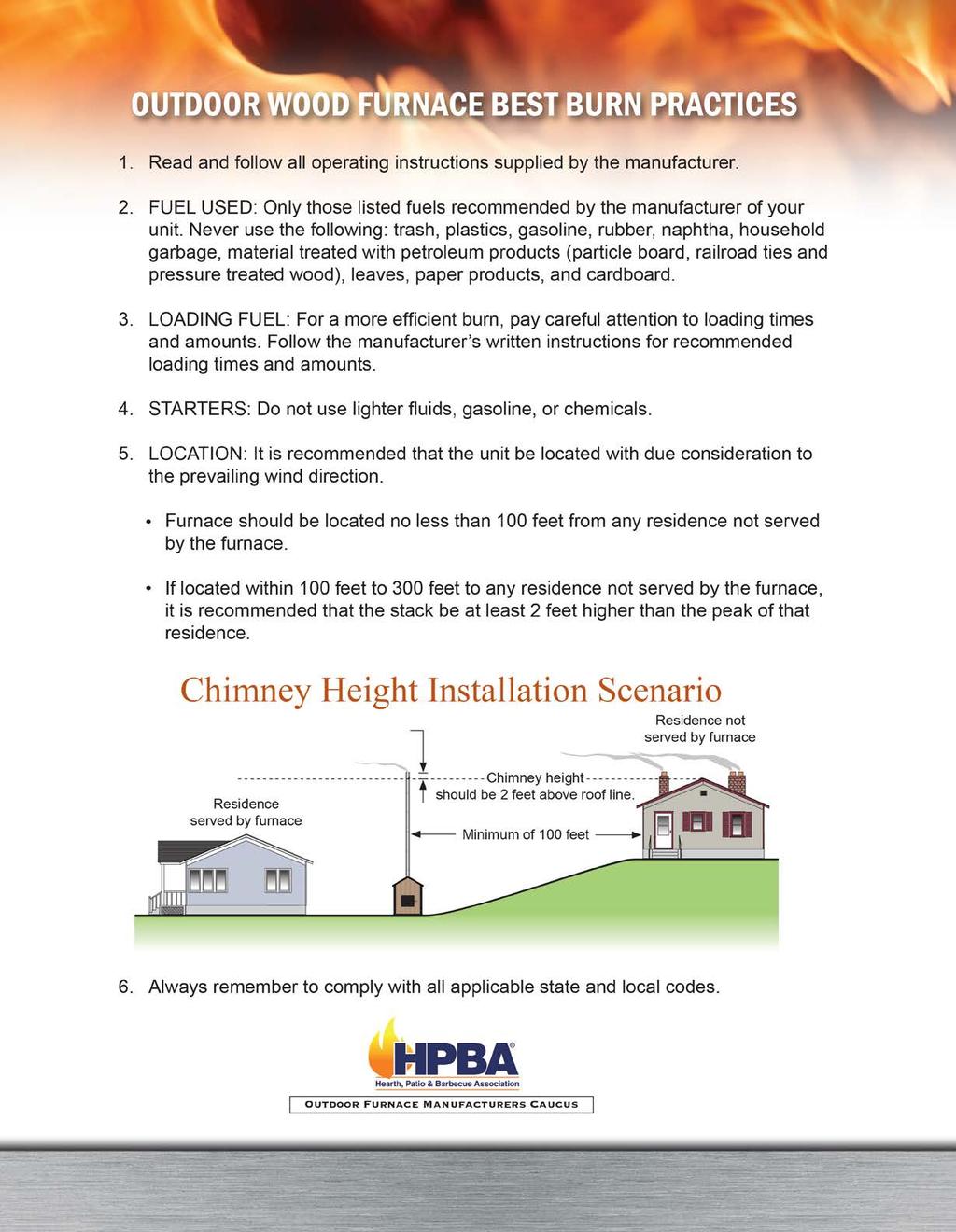
10 CHAPTER 6 MINIMUM CLEARANCE SEPARATION SPECIFICATIONS The HEATMOR furnace, is certified to be installed outside, away from other buildings. Please observe the following Clearance to Combustibles guidelines. If you have any further questions, which are not addressed in this Operators Manual, please contact your local dealer for further information. To HEATMOR Stainless Steel Outdoor Furnace Back. 96 Inches To HEATMOR Stainless Steel Outdoor Furnace Top. 18 Inches To HEATMOR Stainless Steel Outdoor Furnace Front. 48 Inches To HEATMOR Stainless Steel Outdoor Furnace Chimney. 96 Inches To HEATMOR Stainless Steel Outdoor Furnace Sides. 6 Inches Do not store combustible liquids or materials near the furnace. It is not recommended to install the furnace in any form of building. Before installing your HEATMOR Stainless Steel Outdoor Furnace, if in the United States, always check any and all applicable state and local regulations and inform your insurance agent. Before installing your HEATMOR Stainless Steel Outdoor Furnace, if in Canada, always check any and all applicable Provincial and Municipal regulations and inform your insurance agent. HEATMOR Inc. strongly recommends not installing a HEATMOR Stainless Steel Outdoor Furnace within 50 feet of any flammable structure. A HEATMOR Stainless Steel Outdoor Furnace should be located with consideration to your neighbor s property and in accordance with local ordinances. the Best Burn Practices for further operating considerations. HEATMOR Outdoor Furnaces, Model 100 CSS, 200 CSS and 400 DCSS are not designed or certified to be located in densely populated areas. WARNINGS AND PRECAUTIONS Please read the following list of cautions, warnings and dangers before installing and operating your HEATMOR STAINLESS STEEL OUTDOOR FURNACE. If you have any questions or concerns regarding any of the following cautions, warnings, dangers or instructions in this Operations and Maintenance manual, please contact your local dealer. Familiarize yourself with the Best Burn Practices located on the inside front cover. Installation Installation should be performed by a qualified installer and will comply with all the requirements of the authority having jurisdiction over the installation. 1) The HEATMOR furnace is designed for outside installations, away from other buildings. 2) Please observe the following Clearance to Combustibles guidelines. To unit back = 96 inches To unit front = 48 inches To unit top = 18 inches To unit sides = 6 inches To chimney = 96 inches 3) Before installing the furnace, always check any and all applicable state, provincial, and local regulations. 4) HEATMOR Inc. strongly recommends not installing a HEATMOR Stainless Steel Outdoor Furnace within 50 feet of any flammable structure. 5) A HEATMOR Stainless Steel Outdoor Furnace should be located with consideration to your neighbor s property and in accordance with local ordinances. HEATMOR Outdoor Furnaces, Model 100 CSS, 200 CSS and Model 400 DCSS, are not designed to be located in densely populated areas. 6) HEATMOR suggests the use of brass fittings when installing the unit. 7) Before installing the HEATMOR furnace, contact and inform your insurance agent. 8) The HEATMOR Outdoor Furnace is to be installed on a concrete base only. Any attempt to place the furnace on any other surface may void the warranty. 9) Do not connect the HEATMOR furnace to the chimney of any existing heating system. 10) This unit was not designed, nor is it recommended, for use as a stand-alone heating system. A back up source of heat must be in place to prevent the outdoor furnace from freezing and to provide supplementary heat for the heated buildings. 11) Do not pressurize the HEATMOR Outdoor Furnace. This unit is designed to operate under atmospheric pressure only. 12) Place the in-line fill/drain assembly in a location where the drained contents of the HEATMOR will not cause damage to the surrounding areas or it s contents
11 CHAPTER 6 CHAPTER 7A Electrical MODEL 100 PAD SPECIFICATIONS Other 1) Do not connect the electrical components of the HEATMOR Outdoor Furnace to any other electrical appliance. 2) This HEATMOR Outdoor Furnace operates on 115-volt power only. Do not connect the furnace to a 220- volt electrical supply. 3) HEATMOR INC. recommends a licensed professional electrician make all the necessary electrical connections involved with the installation of the furnace. 4) Always disconnect the HEATMOR Outdoor Furnace from the main electrical supply before servicing any of the electrical components of the HEATMOR Outdoor Furnace. 5) Always disconnect any existing electrical connections to any in-house heating system, before installing the outdoor furnace to any existing indoor heating system or appliances. 6) The red wire from the high-limit aquastat on the back of the HEATMOR should be wired to the indoor temperature control to override the thermostat. This will dissipate excess heat in the event of a possible malfunction with the HEATMOR. (The red wire is capped off in the electrical junction box when the HEATMOR is new.) 1) The unit may be connected to an existing indoor boiler system by installing a water-to-water heat exchanger AUGER 26 HOLES FOR HOOK-UPS 12 BASE: OUTDOOR FURNACE SITS ON THIS PAD PATIO STONES OR SEPARATE CEMENT SLAB FOR CONVENIENT LOADING The actual pad size is 50 x 58. This gives approximately 2 extra on all sides of furnace. CAUTION: Do not exceed this length measurement. Width can be wider if desired. The bottom of the loading door is 24 above ground or base of furnace. If you desire to have the leading door higher, you can do so by making the pad depth thicker. Example: 12 instead of 4 or any figure in between. Patio stones or separate cement pad in front of the loading door should NOT be attached to main base of furnace. It is recommended to use steel mesh or R-bar in pad for strength. Benefits to raising the pad: 1. Gives space below the ash auger to place a pail for convenient ash removal. 2. Allows better visibility of the firebox. 3. Less bending when adding wood. 4. Keeps smoke above the operator. 5. Protects the base of the HEATMOR. 1) HEATMOR INC. recommends that you contact a licensed professional plumber to make all necessary plumbing installations between the HEATMOR furnace and the existing heating system of your building(s). 2) Do not operate the HEATMOR furnace until all electrical and water line connections have been properly installed and tested. 3) Do not allow any fire in the firebox until the HEATMOR has the correct amount of water and sand installed. OUTDOOR FURNACE SITS HERE LOADING DOOR SIDE VIEW ASH AUGER CEMENT BASE UNDERGROUND LINES FOUR INCH GRAVEL BASE CEMENT BASE 4-12 HIGHER THAN WHERE THE OPERATOR STANDS. LOADING AREA PATIO STONES OR SEPARATE CEMENT SLAB. GROUND LEVEL 13 14
12 MODEL 200 PAD SPECIFICATIONS CHAPTER 7B CHAPTER 7C MODEL 400 PAD SPECIFICATIONS AUGER 26 HOLES FOR HOOK-UPS The actual pad size is 50 x 70. This gives approximately 2 extra on all sides of furnace. CAUTION: Do not exceed this length measurement. Width can be wider if desired. The bottom of the loading door is 24 above ground or base of furnace. If you desire to have the leading door higher, you can do so by making the pad depth thicker. Example: 12 instead of 4 or any figure in between AUGER 26 HOLES FOR HOOK-UPS The actual pad size is 50 x 88. This gives approximately 2 extra on all sides of furnace. CAUTION: Do not exceed this length measurement. Width can be wider if desired. The bottom of the loading door is 24 above ground or base of furnace. If you desire to have the leading door higher, you can do so by making the pad depth thicker. Example: 12 instead of 4 or any figure in between. BASE: OUTDOOR FURNACE SITS ON THIS PAD Patio stones or separate cement pad in front of the loading door should NOT be attached to main base of furnace. Patio stones or separate cement pad in front of the loading door should NOT be attached to main base of furnace. It is recommended to use steel mesh or R-bar in pad for strength. BASE: OUTDOOR FURNACE SITS ON THIS PAD It is recommended to use steel mesh or R-bar in pad for strength. Benefits to raising the pad: Benefits to raising the pad: PATIO STONES OR SEPARATE CEMENT SLAB FOR CONVENIENT LOADING Gives space below the ash auger to place a pail for convenient ash removal. 2. Allows better visibility of the firebox. 3. Less bending when adding wood. 4. Keeps smoke above the operator. 5. Protects the base of the HEATMOR. PATIO STONES OR SEPARATE CEMENT SLAB FOR CONVENIENT LOADING Gives space below the ash auger to place a pail for convenient ash removal. 2. Allows better visibility of the firebox. 3. Less bending when adding wood. 4. Keeps smoke above the operator. 5. Protects the base of the HEATMOR. LOADING DOOR LOADING DOOR OUTDOOR FURNACE SITS HERE OUTDOOR FURNACE SITS HERE SIDE VIEW SIDE VIEW ASH AUGER CEMENT BASE 4-12 HIGHER THAN WHERE THE OPERATOR STANDS. ASH AUGER CEMENT BASE 4-12 HIGHER THAN WHERE THE OPERATOR STANDS. CEMENT BASE LOADING AREA PATIO STONES OR SEPARATE CEMENT SLAB. CEMENT BASE LOADING AREA PATIO STONES OR SEPARATE CEMENT SLAB. UNDERGROUND LINES FOUR INCH GRAVEL BASE GROUND LEVEL FOUR INCH GRAVEL BASE UNDERGROUND LINES GROUND LEVEL 15 16
 Need to have an airtight seal between the concrete base and the perimeter of the firebox base.")

13 CHAPTER 8 INSTALLATION OF THE HEATMOR FURNACE Installation should be performed by a qualified installer and will comply with all the requirements of the authority having jurisdiction over the installation. Principles 1) Need to have an airtight seal between the concrete base and the perimeter of the firebox base. 2) Need to seal the perimeter of the entire HEATMOR so rodents are not able to find a home inside the HEATMOR. 3) Need to lift the HEATMOR without damaging it. Filling the HEATMOR Outdoor Furnace Initially with Water Before filling your HEATMOR furnace with water, all plumbing connections at the back of the HEATMOR furnace, all electrical hookups, and all heating appliances should be installed and tested for possible leaks. HEATMOR suggests the use of brass fittings when installing the unit. If you have any questions regarding installation of the furnace or any aspect of installation, contact your local dealer. Equipment Required 1) It is not possible to lift a HEATMOR with the forks of a forklift under the HEATMOR. It must be lifted from the top, by the lifting hook. A crane or heavy backhoe works best, although a heavy duty farm tractor is acceptable. a) With a farm tractor, extreme care must be taken to prevent the HEATMOR from swinging and causing damage to the HEATMOR. Placing the HEATMOR on the Concrete Base 2) Before setting the HEATMOR onto the concrete base, it is a good idea to place a solid sheet of the proper reflective air foil (also called bubble foil) between the concrete and the HEATMOR. This will absorb ridges in the concrete and make it easier to apply caulking around the inside perimeter of the base of the HEATMOR. This reflective foil will also reflect escaping heat up into the sand, and help prevent air leaks into the firebox if cement cracks. 3) Make sure the total area of the base (where the sand is going) is on solid concrete. Do not let the base extend past the hole in the concrete where the lines come in. 4) After the HEATMOR is in place perform the following; Caulking around the Firebox Base a) One person should get into the HEATMOR. b) Apply a substantial bead of caulking around the entire inside perimeter of the base. This will give an airtight seal so no air will seep through the sand. This should require about three tubes of High Temperature Silicone. Caulking around the Outside Perimeter of HEATMOR c) With a sharp knife, trim any excess bubble foil that extends past the base of the HEATMOR. d) Apply a bead of caulking around the entire outside Lift Hook Note: Never start a fire inside the firebox until the water jacket is full of water, and sand has been added to the base to the correct level. 1) Close the bladder gate valve located at the front of the HEATMOR furnace. This valve will ensure no water can enter the bladder. 2) Close the bottom supply line valve at the back of the HEATMOR. 3) Open the top return line valve at the back of the HEATMOR. 4) Remove the weighted ball on the roof of the stove from the relief vent pipe. (If so equipped) 5) Connect the water source to the return line leading to the HEATMOR. Use a garden hose to add the water to the return line. 6) Turn on the source of water. 7) The pressured water will now flow through and remove the air out of the return line as the water flows into the HEATMOR. 8) Continue adding water until water flows out the relief vent pipe, onto the roof of the HEATMOR. 9) Turn off the source of water. Rear of Furnace The HEATMOR is now full of water and the return line is also full of water and air free, BUT the supply line leading from the HEATMOR to the building to be heated is still full of air. 10) Close the top return line valve at the back of the HEATMOR. 11) Remove the garden hose that was used to deliver the source of water from the top return line, BUT leave the garden hose valve open. 12) Open the bottom supply line at the back of the HEATMOR (bottom). The pressure of the water in the HEATMOR will now force water from the HEATMOR through the supply line back into the building to be heated. This water will soon discharge from where the garden hose was connected. When there is a steady stream of water flowing, the air will be removed from that supply line. Usually it requires the removal of approximately five gallons of water to ensure the line is air-free. NOTE: The circulator pumps cannot push much air through a system. They are designed to move water not air. 13) Start the circulating pump. Remember to properly bleed air from the pump

14 ABSOLUTELY NO FIRE IN THE FIREBOX WHEN PERFORMING THIS REPAIR. DO NOT PERFORM THIS REPAIR WHEN UNIT WATER TEMPERATURE IS UNSAFE. ALWAYS WEAR PROPER PERSONAL PROTECTIVE EQUIPMENT WHEN WORKING WITH WATER AND CHEMICALS. Maintaining the Correct Amount of Water in the Bladder and in the HEATMOR 1) Keep your bladder valve closed when filling your stove with water, but open at all other times. Your bladder should have a small amount of water in it. Low Water Condition If the water level is below the bladder port when the water heats up, air will enter the bladder instead of water. To remove the air from the bladder, follow step 1 above and make sure there is a good seal. Next: 1) Open the bladder gate valve. 2) CAREFULLY remove the bladder hose, allowing the bladder to empty its contents. 3) After bladder is empty of air/water, re-attach the bladder hose to the bladder gate valve and tighten the hose clamp. Next, follow step 1 above. Initial Installation of Sand Types of sand to use 1) Sand that does not contain clay, rocks or organic matter is appropriate. Use a sand that when packed will not allow air to pass through. Mortar sand, or sand that is used in the redi-mix concrete business is good. Never use gravel. 2) Model 100 CSS furnaces require approximately 0.18 cubic yards, Model cubic yards, and Model cubic yards of sand. Installation 1) Cover the grates with a piece of cardboard. 2) One person enters the firebox. 3) Another person shovels the sand into the firebox while the person inside packs the sand completely, using a piece of wood like a 2 x 4 x 10 inches long. 4) Fill the base with sand, level to the top of the grates. NOTE: NEVER LIGHT A FIRE INSIDE THE FIREBOX UNTIL THE WATER JACKET IS FULL OF WATER AND SAND HAS BEEN ADDED TO THE CORRECT LEVEL IN THE BASE. Stove without Sand NOTE: NEVER LIGHT A FIRE INSIDE THE FIREBOX UNTIL THE WATER JACKET IS FULL OF WATER, AND SAND HAS BEEN ADDED TO THE BASE TO THE CORRECT LEVEL. INSTALLATION SHOULD BE PERFORMED BY A QUALIFIED INSTALLER AND WILL COMPLY WITH ALL THE REQUIREMENTS OF THE AUTHORITY HAVING JURISDICTION OVER THE INSTALLATION. Stove with Sand READ THROUGH THE ENTIRE OPERATIONS AND MAINTENANCE MANUAL BEFORE OPERATING YOUR HEATMOR STAINLESS STEEL OUTDOOR FURNACE
15 CHAPTER 9 SAFE FURNACE OPERATION GUIDELINES OPERATION HEATMOR OUTDOOR FURNACES, MODEL 100 CSS, 200 CSS, AND 400 DCSS ARE CERTIFIED TO BURN WOOD AND APPROVED COAL ONLY. CONTACT HEATMOR FOR APPROVED COAL TYPES. Coal should only be burned in a HEATMOR Furnace equipped with a Shaker Grate System. Burning of other materials may result in serious burns, health consequences, or damage to this furnace and other components of the heating system and may void warranty. ***IMPORTANT NOTICE*** PLEASE REFER TO FILLING YOUR HEATMOR FURNACE WITH WOOD, FOR ADDITIONAL SAFE LOADING PROCEDURES. 8) Do not store combustible liquids or materials near the outdoor furnace. Adhere to the Clearance to Combustibles guidelines. 9) Never use gasoline, kerosene, charcoal, lighter fluid or similar liquids to start, re-start or freshen up a fire. Using such liquids may result in severe burns and injury. 10) When adding water, water treatment or maintaining the HEATMOR furnace, protective clothing must be worn at all times. 11) Never leave the HEATMOR furnace unattended while the firebox door is open or unlatched. 12) Stay clear of any smoke emitting from the firebox. 13) Do not burn garbage, tires, solvents, engine oil, gasoline, or other inappropriate materials. 14) Store ashes outside, in a metal container with a metal tight fitting lid, away from the outdoor furnace and other buildings. No other waste should be placed in this container. 15) Wear a particle mask when removing ashes. 16) Ash auger may be hot after removing ashes. 17) In case of power failure, do not open any doors on the HEATMOR. Monitor the water temperature very closely. freeze protection in this manual. 18) In below freezing weather, if the water temperature in the HEATMOR drops below 40 degrees Fahrenheit, drain all water from the HEATMOR immediately (if there is no anti-freeze in your system). 19) Water additives supplied with a HEATMOR do not give any freeze protection. 20) Always remove the weighted pop off ball before removing more than 5 gallons of water from the HEATMOR. 21) Check daily for creosote buildup until experience shows how often cleaning is necessary. 22) Be aware that the hotter the fire, the less creosote is deposited, and that weekly cleanings can be necessary in mild weather, even though monthly cleanings can be enough in the coldest months. 1) Never open the firebox door if the combustion air blower is operating or if you suspect a roaring hot fire inside the firebox. 2) Never open firebox door immediately after the combustion air blowers have shut off. If the water temperature is very close to the high setting, you should assume the air combustion fans have just shut off. 3) If there is more than a wiff of smoke coming from the chimney and the draft fan is off, do not open the firebox door for at least two minutes. The burn cycle would have just ended and the firebox will be full of unburned gases (smoke) that may ignite when fresh air is introduced. 4) Load the unit with wood carefully, but quickly. After loading wood make sure all debris is cleaned from the firebox doorframe and gasket. Then close firebox door securely. 5) Keep the firebox door, ash auger tube cover cap, top flue cover plate, and the outer door of the HEATMOR furnace closed at all times except for servicing and refueling. 6) Keep the locking handle on the outer door locked at all times when not servicing or refueling to reduce the risk of tampering and possible injury. 7) Never add water to the HEATMOR furnace if the internal water temperature is over 212 degrees Fahrenheit. Failure to adhere to this warning may cause a steam flash and result in an explosion
16 Lighting the HEATMOR for the First Time When lighting the HEATMOR furnace for the first time, all installations must be complete and the furnace must be full of water. It is recommended to open bladder valve, and then build fire to bring the water up to temperature. The lighting process is fairly simple. Please use the following steps simply as a guideline or contact your local dealer for further instruction. Read the entire manual before lighting, so you have a complete working knowledge of the furnace. Ask for a demonstration from your local dealer. It is very important to fully educate all persons who will be lighting and fueling the HEATMOR furnace. PLEASE READ THROUGH ALL LIGHTING YOUR HEATMOR STEPS BEFORE LIGHTING YOUR FURNACE. DEW POINT NOTE: As the temperature inside of the firebox is increasing, there will be some sweating inside the firebox. There may be streams of water running down the inside firebox walls and down the inside of the firebox door. Water may run out onto the fan cover, below the firebox door, and even out the auger tube. THE HEATMOR IS NOT LEAKING! Just as moisture collects on the inside of a warm house window on a cold outside day, the same thing is occurring inside the HEATMOR firebox. The warm moisture in the smoke is condensing on the cold firebox walls of the HEATMOR. In most typical situations, once the water temperature is above approximately 130 degrees Fahrenheit, the sweating will stop because you are above the dew point. 1) Close the green valve, supplying the bladder, located at the front of the stove. 2) Ensure that the furnace is full of water by running five gallons of water onto the roof of the HEATMOR. 3) Ensure that there is 115-volt electrical power supplying the HEATMOR furnace. 4) Place some small pieces of wood (five pounds) with paper into the firebox. 5) Place a few larger pieces of wood (20 pounds) on top of the smaller pieces. 6) Light the fire. 7) Leave the fire box door partially open to allow the fire to start burning. The firebox door should only need to be open about two inches. At this point the smoke should go up the chimney and not out the firebox door. 8) Once the fire is burning rather briskly, close the fire box door and turn off the light switch which in turn will make the combustion air blower(s) operate. 9) Operate the blowers for approximately 10 minutes. 10) Turn off the blowers. Wait a few seconds to allow the combustion to decrease. 11) Open the firebox door and add a substantial amount of wood to the firebox. 12) Turn on the blowers. 13) Securely close the firebox door and outer door. NOTE: Before the furnace is fired up, the furnace is filled with water. While the furnace is filling with water, the bladder is shut off to prevent excess water into the bladder, preventing over fill. When the furnace is freshly filled the water temperature is approximately 50 degrees Fahrenheit. When the furnace is full of water you will notice water coming out onto the roof from the relief vent pipe. At this point the water should be turned off and the bladder valve opened. After the furnace is fired up, the water temperature will start to increase. While the water temperature rises, the water will expand as it heats up, causing the excess water to go into the bladder. It will go into the bladder because it is the place of least restriction. This is another reason why we do not fill the bladder initially, too much water in the bladder at cooler temperatures could cause the bladder to overfill at higher temperatures caused by the expansion of the water during temperature rise
17 Loading Wood into the HEATMOR Please read through the entire HEATMOR Operation and Maintenance Manual and talk to your local dealer for instruction. Ask for a demonstration from your local dealer. It is very important to fully educate all those who will be loading the furnace with wood. Loading a large amount of wood into the HEATMOR furnace once a day is not always best. We have found that you have a more efficient fire and produce less smoke when you add fuel twice a day. Example: Half of the days demand in the morning and half in the evening. The number of loadings and the amount of wood needed will vary depending on the amount of heat being removed. Here are some suggested points to assist you in loading your furnace. 1) Make sure you have your fuel readily available to fill your furnace. (ie. a wheelbarrow full of wood near the furnace) 2) Maintain a clear, clean area in front of the furnace. 3) Open the outer front door. This allows you access to the inner firebox door as well as opens the antirollout device. This allows air into the firebox to decrease the possibility of the exhaust igniting and creating a flash back before you open the main firebox door. 4) Turn on the light switch. The light should turn on and the combustion air blowers should turn off if they were operating correctly. 5) Standing to the right, next to the exterior door, with your left hand and your left arm outstretched, move the fire box door handle out of the safety latch. 6) Crack the firebox door open about two inches and allow any pressure left over in the firebox to escape. 7) Open the firebox door as you step backwards towards the exterior door. This allows you to be out of the way if there is a flash back or exhaust exiting the door opening. 8) Set the firebox door handle into the holder provided on the outer door. 9) After all exhaust has been eliminated, give the ashes over the grates a light stirring with a long rake. 10) Add the necessary fuel to the firebox, being careful not to push ashes into the air boxes. 11) Close the firebox door and latch securely. 12) Turn off the light switch. This will return power to the blowers and turn off the light. 13) Close and lock the exterior door. What should I burn? This furnace is designed to burn well-seasoned cordwood ONLY(unless you have a coal option with shaker grates). Well seasoned wood is wood that has been properly prepared for combustion. Proper seasoning is generally accepted to be wood that has been harvested, split if necessary, and stored for a reasonable amount of time. The most efficient preparation will result in a wood moisture content of 20 percent to 30 percent. If the moisture content is more than 30 percent a significant amount of recoverable heat will be utilized in boiling off the water in the wood which escapes as steam. This loss will accelerate as the moisture content increases. Wood that is too dry will combust too rapidly, thereby increasing heat and fuel loss out of the stack. Our experience indicates that piece diameters of 6 to 8 inches are preferable. Larger pieces (up to 10 inch diameter) will perform well as long as they are properly seasoned. Fortunately, the combustion process will see a mix so that larger/smaller and damper/drier wood combinations can still provide a good result. Learn to load the furnace to most appropriately match the heat demand. Warmer outdoor temperatures indicate a need for smaller loads, thereby matching demand to supply and resulting in higher efficiencies. Being aware that your individual Types of Wood will aid in your decisions. How does a fire burn out? When the temperature of the water has reached its high limit (185 degrees Fahrenheit), the combustion air blower(s) shut off. At this point, the fire banks. When the air combustion blower(s) turn back on, there may not be enough coals to restart the fire. You will then need to restart the fire. If this situation occurs, you may want to transfer to your standard system for better efficiency. A new unit will require the establishment of bed of coals which will aid in re-establishing proper combustion. This may take a few burn cycles. Please refer to the Outdoor Wood Furnace Best Burn Practices located on the inside front cover of this manual
18 Types of Wood There are different types of wood, classified by species, hard or soft, old or new, dry or damp, even larger or smaller. All will burn satisfactorily as long as the proper moisture content and heat load combinations are observed. Therefore, knowing your heat load demands and our fuel supply characteristics is very important. Wood as a Fuel Wood as a fuel contains more moisture than most heating fuels. Therefore, proper management of the process is more important. Heat is required to evaporate the moisture from the fuel. Once moisture is evaporated, proper control of the remainder of the combustion process is also required. At about 600 degrees Fahrenheit the wood will gasify. At this point the fuel/air mixture is fuel rich. With proper secondary air introduction the fuel/air mixture will approach ideal and result in proper combustion. Your Heatmor furnace is designed to create this situation. Wood too high in moisture content results in lower temperatures and unreliable performance. Stages of Combustion During the four stages of combustion, wood breaks down into water, smoke and charcoal. The first stage occurs when wood is placed in the furnace. It must be heated to drive off the moisture. The higher the moisture content, the greater the amount of heat needed and subsequently lost for heating purposes. The drier the wood, the more rapidly it can be heated and passed through this first stage of heating the water. When moisture is being driven from the wood, white smoke may be emitted from the chimney. This is what we call steam smoke. It is mostly water vapor. In the second stage, at 500 degrees Fahrenheit, wood begins to break down chemically. If this smoke is released but not burned, two-thirds of the energy in the wood will be lost. A hot fire is needed to burn the smoke. Efficiency Measurements and Types of Fires There are different ways of expressing efficiency and to correctly compare values. Combustion Efficiency - Input Based The amount of fuel that is completely burned compared to the total amount available for combustion expressed as a percentage. For example: An open bonfire; 100 pounds of wood burns and produces three pounds of ash, which equals 97 percent combustion efficiency. Good combustion efficiency but poor heating efficiency. No heat got into the house. Heating Efficiency - Output Based The percentage of the heat produced that was actually absorbed into the water and transferred into the house from the Heatmor TM. Net Efficiency This is the product of the combustion and heating efficiencies. Ninety percent combustion efficiency times 60 percent heating efficiency results in a 54 percent net efficiency. Loading Of The Furnace Loading the furnace relative to the heat load will result in more efficient performance. More nearly matching your fuel load to the current temperature conditions for an 8 to 12 hour burn will result in longer burn cycles, higher overall burn temperatures and more efficient performance. Your furnace has been rated for an 8 hour burn cycle. Burning wood with less than 30% moisture content will also result in better efficiency. The third stage takes place at temperatures above 1100 degrees Fahrenheit. At this point, the smoke is burning at 100 percent efficiency, as long as the proper amounts of oxygen, temperature and draft are present. If one of these elements is missing, the combustion will be incomplete. The third stage is the most important stage of wood combustion since smoke represents two-thirds of the wood heat. The fourth stage takes place after 1100 degrees Fahrenheit to 2000 degrees Fahrenheit temperatures have been reached. The smoke and gases are completely burned and the charcoal remains, which represents approximately one-third of the wood heat, and allows the fire to re-start when required. When a new charge of wood is loaded, the first stage of combustion begins again. The charcoal heats the fresh wood until it gets hot enough to react and ignite, and the process continues. All four stages can take place concurrently but complete combustion requires proper placement of secondary air and adequate temperatures. This is incorporated in the design of the Heatmor furnace


 Q. Is it a good idea to put the front of my HEATMOR into my wood storage building so I can load the HEATMOR from inside? A. This is never a good idea.")
19 Handling and Storage of Wood Common questions concerning wood storage. 1) Q. Do I have to keep my wood covered? A. It can be more convenient. It is an extra task if snow has to be knocked off the wood before it is loaded into the firebox. Rain and snow landing on the exposed wood will tend to add a certain amount of moisture to the wood. first stage of the burning process. Uncovered wood will still burn. 2) Q. Why is it important to have my loading of wood directly at the furnace when I go to load my furnace? Why must I load my furnace quickly? A. Because of the large firebox and large firebox door, it often only takes a few minutes after opening the door, until the unburned wood in the firebox will ignite and cause smoke to come out the loading door. 3) Q. Is it a good idea to put the front of my HEATMOR into my wood storage building so I can load the HEATMOR from inside? A. This is never a good idea. The HEATMOR, is designed to be placed outside away from all buildings to maintain optimum safety. the Clearance to Combustibles section. (See page 11) 4) Q. What is the best method of handling wood? A. Handle wood as little as possible. Keep the wood covered. Keep the wood storage area neat and tidy. If you have a tractor that can lift pallets or crates, you are well on your way to solving all three concerns. Have available approximately 20 crates (5 feet square x 5 feet high). Take the crates to where you are cutting the wood with the tractor. As you cut, pile the wood in the crates. Use the tractor to move and store the full crates not too far from the HEATMOR. Cover them if you wish. Use the tractor to bring the crates to the front of the HEATMOR, as you need them. Throw the wood into the firebox. 5) Q. What is seasoned wood and how long should I season my wood? A. Seasoned wood is wood that is cut and then stored for a certain amount of time prior to use. We recommend seasoning hardwoods for one to two years and softwoods six months to one and a half years. Ideal moisture content of seasoned wood is percent. Types of Coal There are three main types of coal approved for use in a HEATMOR furnace. They are Pennsylvania anthracite, Eastern Canadian bituminous and Western Canadian sub-bituminous. Coal can vary in size by grade. Use stove coal or a similar size. Smaller sizes may restrict airflow and larger sizes may not burn efficiently, if at all. Please follow all local laws concerning the storage and burning of coal. local dealer for further information on the types of coal available in your local area. Coal as a Fuel Coal, as a fuel, requires more under grate air for burning coal. Each type of coal, whether hard or soft will burn differently, which produces different quantities of ash. For burning coal in the HEATMOR furnaces, the air restrictor should be removed from the combustion air restrictor tube that goes between the airbox and the ash pan. Remove the blower flipper assembly and pry the air restrictor out with a pry bar. This will allow adequate under grate airflow for burning coal. (Refer to airboxes or contact your local dealers for further information on burning coal.) Depending on coal type and airflow needs, an optional Air Block Off can be installed into the airbox to force all air through the ashpan. Handling and Storage of Coal Some types will absorb water and expand; therefore it is recommended that coal must be kept dry. Loading Coal into the HEATMOR Coal may be easily fed into the HEATMOR Furnace with a small metal scoop shovel. With some experimentation you will determine the proper filling technique, amounts and frequency of loading for your HEATMOR furnace while burning coal. Load coal to the bottom of the firebox door frame fill line. Coal should only be burned in a HEATMOR Furnace equipped with a Shaker Grate System. Air restrictor tube holds the air restrictor. Air Block Off 29 30
20 CHAPTER 10 WATER Qualities of Water to Use Water quality will vary from one location to another. Different qualities of water can have a damaging effect on your HEATMOR furnace, pumps, and plumbing components. Please observe the following guidelines for best results. Do not add water from ponds or off roofs. Do not add water exceeding 50 parts per million (ppm) in chlorides. Do not add water over 27 grains hardness - mix this water 50/50 with softened water. Do not add water exceeding 50 ppm silica content. Do not add water from shallow wells. Do not add water from a well that has recently been shocked with chlorine. Water Level Maintenance You can verify the water level of your HEATMOR by checking the fullness of the bladder. The water level gauge ( add water weight) inside the front door of the HEATMOR should be up near the bladder, not down near the shelf. An even better method of gauging the fullness of the bladder is to reach up through the bladder cover plate and feel the bladder. The bladder should still have wrinkles in it when the water temperature is 180 degrees Fahrenheit. If the filling procedures were done correctly, the bladder would have been the last thing topped up after the water jacket of your HEATMOR. Filling your Furnace Initially for further details or contact your local dealer. Removal/Replacement of System Water If a sediment faucet was installed at the back of furnace, it may be used for draining purposes. If you have a sediment faucet installed on the main manifold in the house, that also can be used to drain the HEATMOR. The drained contents of the HEATMOR must be discharged to an area or place where they will not damage property or create an environmental hazard. If you are draining the system because of total system shutdown in cold weather, remember to also drain the supply and return lines to prevent freeze-up. Water Additives ABSOLUTELY NO FIRE IN THE FIREBOX WHEN PERFORMING THIS REPAIR. DO NOT PERFORM THIS REPAIR WHEN UNIT WATER TEMPERATURE IS UNSAFE. ALWAYS WEAR PROPER PERSONAL PROTECTIVE EQUIPMENT WHEN WORKING WITH WATER AND CHEMICALS. Principles of Water Treatment 1) Minimize the corrosion potential of system metallurgy. 2) Keep water in the 8 to 10 ph range. 3) Acts as an oxygen scavenger. 4) Water treatment supplied with the HEATMOR does not give any freeze protection. 5) With proper chemical control, longer equipment life can be achieved. Addition of Water Treatment When installing a completely new system, we recommend that the system first be filled with water only. After two or three days of operation, check that all air is out of the system, and all connections are leak free. Once the entire system is confirmed to be leak free, add the water treatment. To add water treatment to the HEATMOR furnace, follow these steps. 1) Before adding the treatment, drain out a corresponding amount of water. 2) Take a funnel and place it into the relief vent pipe. 3) Pour the entire contents of the water treatment chemical, as supplied, into the HEATMOR furnace. 4) Top up your HEATMOR furnace with water and fill the bladder. Filling the Bladder Initially for details or contact your local dealer. Water Treatment Maintenance / Result The water in the HEATMOR should be chemically analyzed once per year to ensure the proper levels of treatment are being maintained. local dealer as to where to have your water tested. Provide the testing person with an amount of water from your HEATMOR, equal to approximately 20 ounces, in a clean container. The amount of water treatment that has to be added yearly is dependent on how much fresh water you have added to your system since the last test. Be certain to add a water treatment that is approved by your dealer and HEATMOR Inc. To refill your HEATMOR, refer to Filling your Furnace Initially. It is important to add water treatment to the HEATMOR once you have refilled your HEATMOR. For further information on replacing the water in your furnace, contact your local dealer
21 Water Treatment Additives and Safety Specifications Water Treatment Safety Specifications DANGER: CORROSIVE MATERIAL - CAUSES BURNS CAUTION: KEEP OUT OF THE REACH OF CHILDREN Product Identification: Control Water Stove Treatment and Rust Inhibitor Product Manufacturer: Image Supply Inc. Contents: Danger: First Aid: Sodium Nitrate Potassium Hydroxide Hidacid Azure Blue Dye Water Harmful or fatal if swallowed. Avoid skin, clothing and eye contact Avoid breathing mist or vapors Keep container closed and away from children Skin Contact: Immediately flush skin with plenty of water. Remove contaminated clothing and shoes. Wash clothing before reuse. Call a physician if irratation develops and persists. Eye Contact: Immediately flush eyes with plenty of water for at least 15 minutes. Inhalation: Move to fresh air. Ingestion: Harmful or fatel if swallowed. Give several glasses of water followed by citrus juice then olive oil. Get medical attention. Freeze Protection Principles of Freeze Protection When the total system is operating as designed, there is no need to add anti-freeze. However if the water in the outdoor furnace is not going to be kept above 50 degrees Fahrenheit in cold weather, freeze protection must be considered. In a properly designed system, the indoor appliances will automatically come on, generate heat, and keep the supply line, return line, and outdoor furnace from freezing by transferring some of the heat generated, back to the outdoor furnace. This will only happen if the circulating pumps are running. It is recommended to always have a backup system in place. Freeze protection products have lower heat transfer capabilities than water. Freeze protection products will not necessarily inhibit corrosion. Some insurance companies will not insure an outdoor furnace with glycol in the system. Ensure the correct freeze protection product is used. Non-toxic, propylene glycol based, boiler antifreeze is recommended. One such product is DOWFROST HD from Dow Chemicals. Before draining the water, please refer to Removal/Replacement of System Water. When installing a completely new system, we recommend that the system first be filled with water only. After two or three days of operation, check that all air is out of the system, and all connections are leak free. Once the entire system is confirmed to be leak free, add the water treatment and/or freeze protection. Before adding the treatment, drain out a corresponding amount of water. NEVER GIVE ANYTHING BY MOUTH TO AN UNCONSCIOUS PERSON Handling instructions: Wear eye/face protection. Wear goggles and Alkali resistant gloves. Wear suitable protective clothing. Clean up: Contain and/or absorb spill with inert material(e.g. sand, vermiculite), then place in a suitable container. Do not flush to sewer or allow to enter waterways. Use appropriate Personal Protective Equipment. Neutralize area with vinegar. Wash contaminated clothing before reuse. Other precautions: Do not leave unattended when open. Do not reuse container. This product does not provide any freeze protection. FOR MEDICAL EMERGENCIES CALL United States: INFOTRAC Canada:
 Drain the correct amount of water from the system for the products being added.")
22 CHAPTER 11 Adding Freeze Protection Products ABSOLUTELY NO FIRE IN THE FIREBOX WHEN PERFORMING THIS REPAIR. DO NOT PERFORM THIS REPAIR WHEN UNIT WATER TEMPERATURE IS UNSAFE. ALWAYS WEAR PROPER PERSONAL PROTECTIVE EQUIPMENT WHEN WORKING WITH WATER AND CHEMICALS. 1) Drain the correct amount of water from the system for the products being added. 2) Take a funnel and place it into the relief vent pipe. 3) Pour the contents of the freeze protection products, into the HEATMOR furnace. Do not pressurize the HEATMOR ; do not attempt to thread fittings onto the relief vent pipe and pump additives into the HEATMOR under pressure. 4) Top off your furnace with water and fill your bladder. Filling the Bladder Initially for details or contact your local dealer. BLADDER ASSEMBLY Principles It is best not to have the system water, that is in the water jacket, exposed to the atmosphere. This is because of system water loss through evaporation. When system water is lost, it must be replenished or soon the water jacket would be empty. Not only is replenishing lost system water a nuisance, it is also accelerating the corrosion process throughout the total system, because adding fresh system water is also adding more corrosion causing minerals. The challenge is to maintain an airtight system, while at the same time, allowing for the expansion and contraction of system water as it warms and cools. This is accomplished in a HEATMOR design through the rubber bladder. Bladder Principle of the Bladder The HEATMOR is designed to be a semi-closed system. The bladder is a reservoir that accepts the increased volume of water that results when the water within the water jacket expands as it is heated. Similarly, when the water within the water jacket cools down, water is drawn out of the bladder. Operation of the Bladder The bladder has a capacity of approximately 8 gallons. Normally, the bladder should have a small amount of water in it at all times. As the furnace cycles, the amount of water in the bladder will increase and decrease. If at any time the furnace is requiring additional water it will use the reserve water in the bladder before having to be topped up. Bladder Filling the Bladder with Water 1) Keep your bladder valve closed when filling your stove with water, but open at all other times. Your bladder should have a small amount of water in it. Maintenance / Result To maintain your furnace bladder simply keep the bladder so that it has a small amount of water in it, so the bladder continues to supply the water jacket with water. If the water level does run low, the possibilities of water boiling and firebox warping are increased

 Remove the water level gauge and pull the rope through the eyelet. 4) Remove the hose clamp from the bladder gate valve.")
 Install the new bladder with the valve stem in the rear of the bladder compartment with the hose coming down through the center of the tube.")
23 Removal and Replacement of the Bladder ABSOLUTELY NO FIRE IN THE FIREBOX WHEN PERFORMING THIS REPAIR. DO NOT PERFORM THIS REPAIR WHEN UNIT WATER TEMPERATURE IS UNSAFE. ALWAYS WEAR PROPER PERSONAL PROTECTIVE EQUIPMENT WHEN WORKING WITH WATER AND CHEMICALS. 1) Turn off the (green) bladder gate valve located at the front of the HEATMOR furnace to the left of the thermometer. 2) Remove the bladder cover plate held in place by two wing nuts. 3) Remove the water level gauge and pull the rope through the eyelet. 4) Remove the hose clamp from the bladder gate valve. 5) Pull the bladder hose away from the bladder gate valve and let the water drain from the bladder. Be careful, it could be warm. 6) Remove the old bladder and install the new bladder. 7) Install the new bladder with the valve stem in the rear of the bladder compartment with the hose coming down through the center of the tube. Connect the tube to the bladder valve s 1/2 inch barbed fitting and tighten hose clamp. 8) Thread the rope over the bladder and through the eyelet. Attach the add water plate onto the rope. 9) Open the bladder gate valve and follow the Filling the Bladder with Water instructions. Bladder Gate Valve and Bladder Hose Principle of the Bladder Gate Valve and Bladder Hose The bladder gate valve provides water flow control in maintaining the bladder and filling the furnace with water. The bladder hose provides a means for the water to freely flow from the water jacket to the bladder allowing expansion and contraction. WHEN THE HEATMOR FURNACE IS OPERATING, THE BLADDER GATE VALVE MUST BE OPEN. Bladder Gate Valve Maintenance / Result To maintain the bladder gate valve, open and close the valve periodically to prevent it from seizing. Ensure that the hose clamp is tightly fastened, securing the bladder hose to the bladder and to the bladder gate valve. Bladder Gate Valve and Bladder Hose (cont.) 5) Remove the old bladder gate valve and install the new bladder gate valve. 6) Attach the bladder hose to the bladder gate valve and tighten the hose clamp. 7) Keeping the bladder gate valve closed, add water until furnace is full. 8) Open the bladder gate valve and follow the Filling the Bladder with Water instructions. 9) Turn on the power to the furnace. Water Level Gauge Principle of the Water Level Gauge The water level gauge simply gives you an accurate reading of when the bladder is full or empty of water. Maintenance / Result To maintain your water level gauge, ensure that it can move freely through the eyelet. If it does not move freely, the risk of the rope wearing and breaking or inaccurate readings are possible. Removal and Replacement 1) Drain some of the water from the furnace to allow you to maneuver around the bladder. 2) Remove the water level gauge from the rope. 3) Remove the rope and replace it with a new water level gauge rope. 4) Thread the rope over the bladder and through the eyelet. 5) Attach the water level gauge. 6) Refill the bladder referring to the instructions Filling the Bladder with Water instructions. Bladder Cover Plate Principle of the Bladder Cover Plate The bladder cover plate simply gives protection to the bladder from possible back flashes and excess heat. It helps hold up the bladder in position, and when it is removed allows a large space to service the bladder. Add Water Sign Removal and Replacement ABSOLUTELY NO FIRE IN THE FIREBOX WHEN PERFORMING THIS REPAIR. DO NOT PERFORM THIS REPAIR WHEN UNIT WATER TEMPERATURE IS UNSAFE. ALWAYS WEAR PROPER PERSONAL PROTECTIVE EQUIPMENT WHEN WORKING WITH WATER AND CHEMICALS. Removal and Replacement To remove and replace the bladder cover plate, loosen the wing nuts and install the new cover plate. Tighten the wing nuts. Bladder Cover Plate 1) Turn off the power to the furnace. 2) Drain some of the water from the furnace to prevent water from draining while you are replacing the valve. 3) Loosen the hose clamp holding the bladder hose to the bladder gate valve. 4) Remove the bladder hose from the bladder gate valve and let the water drain from the bladder

 water from the bottom of the water jacket.")
24 CHAPTER 12 CHAPTER 13 WATER JACKET Principles of the Water Jacket Water within the water jacket absorbs heat produced in the firebox. The heated water is used to transfer heat from the HEATMOR into the building needing heat. The water jacket and the firebox are one welded component and can be replaced. Maintenance Keep the proper concentration of water treatment in the water. Supply Line and Return Line Threaded Connectors Principles The HEATMOR furnace is designed to draw the supply (hot) water from the bottom of the water jacket. This may seem irregular (people know hot water rises), but this method mixes the water in the water jacket better and often extends pump life. The return (cooler) water connects to the, upper, rear spud of the HEATMOR. A circulator (pump) moves the water at approximately three to 10 gallons per minute, through both lines under very little pressure (3 psi). Always attach a BRASS fitting into the STAINLESS STEEL spud to prevent galvanic corrosion. Relief Vent Pipe and Weighted Pop off Ball Principles The relief vent pipe is connected to the top of the water jacket. When the water within the water jacket is heated it expands, the water will expand into the bladder, instead of out onto the roof. FIREBOX AND OTHER COMPONENTS Firebox Principles of the Firebox Wood is burned inside the firebox to generate heat. This heat is absorbed into the water in the water jacket. The firebox and water jacket are one welded component and can be replaced. When the water is up to temperature and the combustion air blowers are off, the firebox must be airtight. Operation of the Firebox Temperatures within the firebox can reach 2000 degrees Fahrenheit. Smoke exits from the firebox into the flue. During normal operation, there will be a slight buildup of black creosote on the firebox walls. This buildup will sometimes appear flaky. Maintenance / Result Wood should not be thrown into the firebox in a rough manner. Creosote should never have to be scraped off the firebox walls. Removal and Replacement 1) Remove all wood and let the unit cool down. 2) Drain all water and disconnect main power. 3) Remove the total roof of the HEATMOR. 4) Remove sides of the HEATMOR. 5) Remove the doors and corners of the HEATMOR. 6) Remove the insulation. 7) Disconnect plumbing, aquastat and high limit and all electrical from the water jacket. 8) Loosen the firebox / base connector clamps. 9) Lift the old firebox / water jacket component off the base. 10) Lift the new firebox / water jacket component onto the base. 11) Apply new silicone. 12) Reverse the above. Firebox Relief Vent Pipe 39 40

25 Firebox Door Principles of the Firebox Door The firebox door is water cooled to prevent warping of the door. It also acts like a water jacket, absorbing heat from the fire, and placing that energy into the water. Being water cooled, the front of the firebox door will never be hotter than the water. The cold outside atmospheric air is drawn over the warm surface of the firebox door, by the combustion blowers, which is then warmed and forced into the firebox as warmed combustion air. This lessens the time needed for the interior of the firebox to reach that high smoke burning temperature. It is important that the firebox door seal maintains an airtight seal. Operation of the Firebox Door Water from the main waterjacket flows in a loop between the firebox door and the waterjacket by natural thermal siphoning. Since there is no pump involved, there is very little pressure. During this process, the water cools the door and the water in the door is heated. Firebox Door Handle Firebox Door Handle shut. Make a collar of cardboard between the jaws of two pairs of vice-grips and clamp the door hoses tight at the center point of their length. 4) Loosen the hose clamps and remove the door hoses from the firebox door. 5) Loosen and remove the nuts and bolts holding the firebox door on to the hinge. 6) Remove the firebox door from the hinges and remove the handle from the firebox door. To replace the firebox door, follow these steps: 1) Replace the bolts and nuts onto the new door just as they were removed. 2) Hang the firebox door on the hinges loosely, with the nuts just slightly more than finger tight, and attach the handle on to the firebox door allowing the handle to just barely float freely. Note: Ensure there is a tight seal around the firebox door frame while it is closed and latched shut. The firebox door must remain parallel with the door frame. 3) Close the firebox door and allow the handle to rest freely in the latch. 4) Get the firebox door parallel with the door frame ledge and tighten the nuts and bolts a little more firmly onto the hinges. You may want to block up the firebox door until the hinge is re-tightened. 5) Re-attach the door hoses, tighten the hose clamps, and unclamp the vice-grips. 6) Light a fire in the firebox; then ensure that there are no air leaks. You will be able to detect them by noticing smoke escaping through any air leaks, while the blowers are running. Safe Operating Guidelines for further instructions on how to safely open and close the firebox door or contact your local dealer. Maintenance / Result A properly adjusted firebox door will not allow smoke to enter or escape the firebox. Maintain a tight seal all around the perimeter of the firebox door at all times. There may be times when the perimeter of the firebox door will build up with creosote strings, especially along the bottom. To keep the perimeter clean, occasionally scrape down to the steel. Do not cut, scrape or disturb the actual soft, pliable seal. Keep the door correctly adjusted on the hinges so that the pliable seal is being forced against the firebox ledge. Keep all nuts and bolts on the handle, latch and hinges properly adjusted. Note: If there is smoke leakage around the firebox door or one corner of the door, it is adjustable. 7) Lift the door handle off the latch and allow it to rest loosely. 8) With two 1 1/8 inch wrenches, loosen the appropriate hinge (top or bottom) so it is slightly more than finger tight. (Use only the bottom nut to adjust.) 9) While the bolt is slightly tight, rap the nut between the hinge halves, with a punch and hammer. 10) With hinge bolt reset, tighten the lower nut. 11) The top and bottom firebox door should remain parallel with the door frame. If it tends to sag, block it up with appropriate blocking until the hinge is re-tightened. The seal itself consists of a rope in the groove of the firebox door, covered with high temperature silicone. Failure to manage and maintain the firebox door could result in premature replacement of parts and a buildup of creosote. (When replacing the Firebox Door, it is recommended to replace the Door Hoses at this time.) ABSOLUTELY NO FIRE IN THE FIREBOX WHEN PERFORMING THIS REPAIR. DO NOT PERFORM THIS REPAIR WHEN UNIT WATER TEMPERATURE IS UNSAFE. ALWAYS WEAR PROPER PERSONAL PROTECTIVE EQUIPMENT WHEN WORKING WITH WATER AND CHEMICALS. Removal and Replacement To remove the firebox door, follow these steps: 1) Turn off power to the combustion air blowers. 2) Ensure that the fire in the firebox is extinguished. 3) Stop the flow of water from the water jacket through the door hoses by pinching the two door hoses 41 42

 in the elbows is possible over time, which slowly reduces the water flow through the door.")

 Turn off power to the air combustion blowers.")
 Loosen the hose clamps on each elbow. 5) Remove each of the door hoses from the elbows. 6) Using a wrench, unscrew each of the door elbows, note how the elbows are angled.")
26 Firebox Door Hoses and Elbows Principle of the Door Hoses The door hoses allow water to circulate between the firebox door and the water jacket. Operation of the Door Hoses The door hoses allow water from the water jacket to pass through the firebox door, through thermal siphoning. Firebox Door for further details. Maintenance / Result Maintaining the door hoses and elbows ensures that water is able to flow through the door. Build-up (calcium) in the elbows is possible over time, which slowly reduces the water flow through the door. If water does not flow freely through the hoses to the firebox door, you may hear popping sounds in the door. Once the hoses are around five years old or if they show signs of wear, they should be replaced. Replacement of hoses or cleaning of the elbows is always easier if the water is cool rather than hot. To clean the elbows, remove the hoses and use a pipe cleaning brush to clear out the build-up. Door Hose 11) Check for leaks. 12) Repeat the steps to change additional door hoses. Removal and Replacement To remove and replace the elbows, use the following steps: 1) Turn off power to the air combustion blowers. 2) Ensure that the fire in the firebox is extinguished, which will allow the water to cool. 3) With hose clamps or vice-grips, pinch each door hose in the middle of the hose, creating a tight seal. 4) Loosen the hose clamps on each elbow. 5) Remove each of the door hoses from the elbows. 6) Using a wrench, unscrew each of the door elbows, note how the elbows are angled. 7) Replace the door elbows using pipe compound and a wrench. Ensure the elbows are secure and angled correctly so the hoses will slide on easily. 8) Push the door hoses onto the new elbows. 9) Tighten the hose clamps on each top and bottom hose, securely fastening the door hose to the elbow. 10) Remove the vice-grips pinching the door hoses. This will allow water to flow through hoses. 11) Check for leaks. Firebox Door Handle Elbow ABSOLUTELY NO FIRE IN THE FIREBOX WHEN PERFORMING THIS REPAIR. DO NOT PERFORM THIS REPAIR WHEN UNIT WATER TEMPERATURE IS UNSAFE. ALWAYS WEAR PROPER PERSONAL PROTECTIVE EQUIPMENT WHEN WORKING WITH WATER AND CHEMICALS. Removal and Replacement To remove and replace the door hoses, use the following steps: 1) Turn off power to the air combustion blowers. 2) Ensure that the fire in the firebox is extinguished, which will allow the water to cool. 3) With hose clamps or vice-grips, pinch the door hoses in the middle of the hose. 4) Before removing the old door hose, cut the new pieces of door hose, one at 19 inches and the other at 21 inches. These measurements are critical. 5) Pinch the new door hose in the middle of the hose, creating a tight seal. 6) Loosen the hose clamps on each end of the door hose. 7) Remove the first end of the door hose needing Clamping hose replacement. 8) Push on the end of the new door hose and repeat the steps for the opposite end of the hose. 9) Tighten the hose clamps, securely fastening the door hose to the nipple on the furnace or firebox door. 10) Remove the vice-grips pinching the door hoses. This will allow water to flow through. Principles of the Firebox Door Handle Fastened to the firebox door, the handle provides a secure method of controlling the opening and closing of the firebox door. By opening the firebox door, (only until the door handle hits the second stage of the safety latch), gives a space for fresh air to enter the firebox without the risk of a flash back. The firebox door handle is also designed to stick to the firebox door handle holder on the outer door. This procedure prevents either of the doors closing while the Heatmor TM is being loaded with wood. Maintenance / Result To maintain the door handle, ensure the handle closes and opens fairly easily. If the handle closes too hard, it will be hard to open and close the door. If the closure is too loose, it will be harder to obtain a perfect seal around the door. If you do not have a firm seal, you could potentially create an air leak resulting in further complications. Air Leaks for further details or contact your local dealer. You can adjust the two bolts on the latch for correct closure. Firebox Door Handle Removal and Replacement To remove the handle, use the following steps. Firebox Door Handle 1) Turn off power to the blowers. 2) Ensure the fire in the firebox is extinguished. 3) Loosen and remove the nut on the bearing and the nut on the mounting plate. 4) Replace the handle 5) Replace and tighten the nut on the bearing and the nut on the mounting plate


27 Firebox Door Hinge Principle of the Firebox Door Hinge Supports the firebox doors and allows for adjustment. Maintenance / Result The adjustable hinge works in conjunction with the door handle and the firebox door. The hinge has slotted holes so the firebox door can be adjusted to provide a solid fit against the firedoor frame. Secure and stable, the hinge allows the firebox door to swing free and smooth. Firebox Door Latch Principles of the Firebox Door Latch The safety latch is designed to provide additional safety by preventing the firebox door from opening too quickly, potentially allowing a flashback. The latch is adjustable and replaceable. Maintenance/result The latch is adjustable with the two bolts. The two bolts must be tightened firmly. When properly adjusted, the firebox door handle will close and open with ease and create a perfect seal around the door. Firebox Door Hinge Firebox Door Magnet against the firebox door frame. Keep all nuts and bolts on the handle, and latch and hinges properly adjusted. The seal itself consists of a fiberglass rope in the groove of the firebox door, covered with high temperature silicone. Failure to manage and maintain the firebox door gasket could result in air entering into the firebox when the combustion air fans are off or smoke escaping around the seal when the combustion air blowers are running. Air entering the firebox when the fans are off results in the wood continuing to smolder, resulting in the furnace overheating and more than a wiff of smoke emitting from the chimney. Often, this type of smoke has an unpleasant odor. Creosote will also be formed. When the fans are running and the door seal is not sealing tightly, smoke will be forced through the leaking door seal. This causes the front of the furnace to be smoke filled and soon the front of the firebox will be covered with soot. Premature replacement of parts and a buildup of creosote will result. Removal and Replacement ABSOLUTELY NO FIRE IN THE FIREBOX WHEN PERFORMING THIS REPAIR. DO NOT PERFORM THIS REPAIR WHEN UNIT WATER TEMPERATURE IS UNSAFE. ALWAYS WEAR PROPER PERSONAL PROTECTIVE EQUIPMENT. Firebox Door Magnet Principles of the Firebox Door Magnet The firebox door magnet provides a means of holding both the outer front door and the firebox door completely open while the operator is loading wood into the HEATMOR. Operation 1) Open the firebox door as you step backwards towards the exterior door. This allows you to be out of the way if there is a flash back or smoke exiting the door opening. 2) Stick the firebox door handle onto the firebox door handle magnet provided on the outer door. 3) To remove the firebox door from the magnet, turn the handle to the left and pull the inner door away by the handle. Firebox Door Gasket Principles of the Firebox Door Gasket The firebox door gasket creates an airtight seal between the firebox door frame and the firebox door. It is a pliable seal that can be removed and replaced if damaged or worn. Maintenance/Result Occasionally, scrape the perimeter of the firebox door to keep it clean. Do not cut, scrape or disturb the pliable seal. Keep the door correctly adjusted on the hinges to ensure the pliable seal is being forced Firebox Door Gasket 1) Using a sharp knife, carefully cut away the silicone seal around the firebox door seal channel. 2) Remove the old gasket from underneath the old silicone. 3) Remove all old silicone with a wire wheel or steel brush. 4) Replace with a single length of new gasket material. Do not pack or over stretch the new gasket. Once in place allow, the material to relax before cutting to length. 5) Cover the door rope with silicone and tool to a smooth, flat, finish. 6) Leave the firebox door open for 24 hours to allow silicone to dry completely. NOTE: You will need 78 inches of 1 inch door rope material plus two tubes of caulking. The door rope kit is available from your HEATMOR dealer. Firebox Door Frame Principles of the Firebox Door Frame To provide a small edge that will seal into the firedoor gasket to provide an airtight seal. Maintenance / result Keep the door frame cleaned down to the steel at all times. Failure to do so results in a build up of creosote, resulting in a barrier to an airtight seal, air leaks and premature gasket replacement. Firebox Door Frame 45 46


 Remove the black, high temperature silicone bead at the bottom of the firebrick. 4) Using a pry-bar, remove the broken brick. 5) Replace the broken brick.")
 Push the ashes to the back of the firebox or remove all the ashes from the firebox. 3) Run a small prybar around the perimeter of the grate and the edge of the ash pit to loosen the grate.")
28 Firebox / Base Connector Clamps Principles of the Firebox / Base Connector Clamps To allow easy separation of the firebox / water jacket assembly and the base, if repairs are needed to either assembly. Firebrick Principles of the Firebrick Once heated, the firebricks hold heat for a long period of time. This creates a warm firebox between cycles. Because of this heat, when the combustion air blowers start, the fire inside the firebox can re-ignite and reach the smoke burning temperature of 1100 degrees Fahrenheit much faster. Maintenance/Result Allow the ashes to bank up against the firebrick to act as a cushion against hard knocks of wood. If bricks are broken, they should be replaced as soon as possible. Firebrick Removal and Replacement 1) Let the fire go out and allow the ashes to cool completely. Remove the ashes from the firebox. 2) Crawl into the firebox. 3) Remove the black, high temperature silicone bead at the bottom of the firebrick. 4) Using a pry-bar, remove the broken brick. 5) Replace the broken brick. 6) Apply a new bead of high temperature silicone along the base of the brick. Standard Grates Removal and Replacement 1) Allow the ashes to burn completely and extinguish. 2) Push the ashes to the back of the firebox or remove all the ashes from the firebox. 3) Run a small prybar around the perimeter of the grate and the edge of the ash pit to loosen the grate. 4) Lift out the broken grate. 5) Clean the edge of the ash pit in which the new grate will sit. 6) Install the new grate. Make sure to install the new grate with the narrow width of the slot towards the fire. Optional Shaker Grates Using Your Shaker Grate System There are two main modes of operation for the Shaker Grate System. These are Shake mode and Dump mode. Shake mode is used mainly for daily use and consists of handle movement with the stop in place. Moving the handle back and forth with the stop in place allows for the breaking up and release of small pieces of klinker and ash into the ashpan. This should be done daily or whenever coal is added to the furnace. See figure 1. The second mode is Dump mode and consists of handle movement with the stop moved out of the way. Moving the handle back and forth, with the stop out of the way, allows for full movement of the shaker grates as well as the breaking up and release of large pieces of klinker into the ashpan. Dump mode is needed when the klinker buildup on the shaker grates is such that it causes restriction of airflow to the fire. See Figure 2. Figure 1 Principles of the Standard Grates Grates allow combustion air from the combustion air blowers to pass from below the grates, up through the grates, through a shallow depth of ashes and then to the bottom of the burning fire. This way the ashes will burn completely into a fine powder that will flow through the grates into the ash pit. Because air is being forced through the ashes, the glowing embers will be more apt to ignite and set the wood ablaze. Maintenance/Result Standard Grates 1) Never make the slots in the grates wider than factory dimensions. If hot coals can pass through the grates, warping of the grates may result. 2) Make sure the grates are always resting in the grooves of the ash pit. If the grates move out of place, it may result in hot coals slipping under the grates causing warpage of the grates. 3) Make sure the narrow side of the slot is next to the fire. 4) Replace broken grates immediately or a chain reaction of broken grates may result. 5) The grates will not break under reasonable knocks of heavy wood. During normal operation the shaker grates must be in a neutral position as shown in Figure 3. It is important that after using the shaker system in dump mode, all klinker and ash is cleared out from the ashpan leaving NOTHING behind. Anything left under the shaker grates can re-ignite causing damage to the shaker grates. Figure 2 Figure


29 Sand Flash Curtain / Heat Shield Principles of Sand in the Base of the Firebox The HEATMOR furnace, in boiler terms, is a dry base boiler. This is to say there is no water around the base of the firebox. The firebrick and sand hold and release heat to the firebox during the off cycle. This shortens the time when smoke will be emitted. A sand base provides complete corrosion protection to the most corrosion prone area of a furnace. Maintenance/Result Sand The sand should never need to be removed. When stirring the ashes, rake only the area over the grates. There is no need to stir the areas where the sand is located. Maintain the sand level to the top of the grates. Check the level on a yearly basis and add sand if necessary. page 20 for types of sand to use. Principles of the Flash Curtain / Heat Shield The purpose of the flash curtain is to decrease the amount of smoke emitted from the door when loading wood into the firebox. The flash curtain decreases the size of the firebox opening, making that size more in proportion to the area the natural draft of the chimney will draw from. As a heat shield, the flash curtain restricts the amount of direct heat that contacts the firebox door directly. ABSOLUTELY NO FIRE IN THE FIREBOX WHEN PERFORMING THIS REPAIR. ALWAYS WEAR PROPER PERSONAL PROTECTIVE EQUIPMENT. Removal and Replacement 1) Allow the ashes to extinguish and then remove all the ashes from the firebox. 2) Allow the water to cool down. 3) One person should get into the firebox and with a small scoop, remove the sand from around the ash pit. 4) Replace as above. Maintenance/Result Leaving the flash curtain in place is effective for the principles outlined above. Removal and Replacement 1) The plate is slotted at the top and fits loosely onto two hooks, installed above the firebox door opening. 2) With the ashes cooled down, lift up on the plate until it releases itself from the hooks. Flash Curtain Proper placement of Flash Curtain 49 50
 and Flipper Assembly(s) THE FLIPPER MUST OPERATE PERFECTLY OR PROBLEMS QUICKLY ARISE.")
30 CHAPTER 14 AIR SUPPLY Maximum draft should not exceed 0.20 inches water column, if exceeded could cause solid fuel fire to burn out of control. Combustion Air Blower(s) and Flipper Assembly(s) THE FLIPPER MUST OPERATE PERFECTLY OR PROBLEMS QUICKLY ARISE. Principles The combustion air blowers and flipper assemblies supply air for combustion inside the firebox. The flipper assemblies keep air out of the firebox when combustion is not needed. These components are removable and serviceable. Operation of the Combustion Air Blower(s) and Flipper Assembly(s) When the water temperature reaches the high water temperature setting, the aquastat turns the blower(s) off. At this point, the hinged flipper falls shut, preventing air from getting into the firebox. Flipper Assembly When the water temperature reaches the low water temperature setting, the aquastat turns the blower(s) on. At this point, the hinged flipper opens from the force of the blower(s) and allows air into the firebox. The hinged flipper must completely open and close all of the time. When it is closed, it must seal completely. If more than a wiff of smoke is coming from the chimney when the blower(s) has been off for approximately 10 minutes, this is a strong indication the hinged flipper is not shutting properly. Maintenance / Result Clean the fin blades of the squirrel cage fan. Ensure the flipper assembly is clean and seals completely when closed. Steps to Maintain your Blower / Flipper Assembly. 1) Turn off the main power supply to the furnace. 2) Loosen and remove the two thumb nuts securing the blower / flipper assembly to the large air tube, and remove the blower / flipper assembly. 3) With a small brush, scrape any dust or residue that has accumulated on the fins of the blower. 4) With a small brush or scraper, scrape any dust or residue built up on the flipper assembly. 5) Ensure the flipper is resting completely on its seat. If it is not resting completely, perhaps there is dust or soot built up on the flipper, or some other obstruction not allowing it to close tightly. 6) Securely fasten the blower/flipper assembly back to the large air tube ensuring there are no air leaks. Removal and Replacement 1) Turn off the main power supply to the furnace. 2) Loosen and remove the thumbnuts securing the blower / flipper assembly to the air tube. 3) Disconnect the electrical wire from the blower. 4) Remove the flipper assembly from the blower by removing the four bolts. This will require a 7/16 inch wrench. 5) Attach the existing flipper assembly to the new blower. 6) Rewire the electrical wire to the blower. Contact a licensed electrician if you have any questions. 7) Securely fasten the blower back to the air tube ensuring that there are no air leaks. THE FLIPPER MUST OPERATE PERFECTLY OR PROBLEMS QUICKLY ARISE. If the flipper is unable to open and close freely, or remains partially open or partially closed, the furnace will starve for air resulting in a smoldering fire instead of an intense fire. More smoke and creosote is the result. If the flipper is not operating correctly, it causes a snowball effect of problems. MAINTAIN THE FLIPPER! Air Box(s) Principle The air box is designed to distribute the appropriate percentage of air from the blower(s), into different areas of the firebox so the fire will burn efficiently and clean. Maintenance / Result Check for ashes in the air box. If ashes are in the air box, they may interfere with the opening and closing of the flipper. If ashes cover the air outlets, less air will get into the firebox. When raking ashes, be careful not to pull the ashes over or into the air box/(s). Be certain the ashes are cold and extinguished before attempting to remove ashes from the air box. To maintain the air box, remove the blower / flipper assembly and clean the ashes out of the air box with a mini-vacuum that is made for ashes, metal brush or metal scraper. You may need to loosen up hard packed ashes. Securely fasten the blower / flipper assembly back onto the large air tube ensuring there are no air leaks. Air Box 51 52


31 CHAPTER 15 Combustion Air Restrictor Tube Principle The combusion air restrictor tube allows air flow from the airbox to the ashpan. It helps to provide combusion air into the ashpan, through the grates and to the bottom of the charge of wood. Operation The combustion air restrictor tube is designed with a restrictor inside of the tube. This feature is installed on all standard wood burning HEATMOR furnaces. This restrictor helps to divert combustion air above the grates as well as allow proper airflow to the underside of the grates. This standard setup is for wood burning. If coal is going to be burned, the restrictor must be removed to allow more under grate airflow and less over grate airflow. This is done by removing the combustion blower/flipper assembly and using a small prybar to remove the restrictor. Maintenance Maintenance should be completed regularly to ensure no ash has accumulated inside the combustion air restrictor tube, limiting airflow. If the furnace does not have proper airflow, the combustion efficiency is reduced, resulting in increased smoke and creosote. Automatic Fan Switch (A.F.S.) The Automatic Fan Switch must operate correctly for safe operation of the Heatmor Combustion Air Restrictor Tube Automatic Fan Switch Principle The fan switch turns the fan on while the outer door is opened to clear the possible excess fuel build up in the firebox. Along with normal recommended, safe firebox door opening practices, the risk of a flash back is greatly reduced. Operation The Automatic Fan Switch automatically turns on the fan when the front outer door is open. The Automatic Fan Switch can be over ridden by the Front light and Combustion Air Blower Control Switch and the high limit will also override the Automatic Fan Switch. Maintenance/Result Ensure that the outer door closes properly to activate the Automatic Fan Switch. If the outer door does not close properly the switch could stay in the fan on position or if the Automatic Fan Switch fails in the fan on position, the Heatmor combustion fan will continue to run until the high limit is tripped. Ensure that the Automatic Fan Switch is working properly: if the Heatmor is off when you approach the Heatmor, the fan should come on when you open the outer door, if it does not, then your Automatic Fan Switch has failed in the fan off position. CHIMNEY AND TOP FLUE Chimney Principles The principle of the chimney is to discharge smoke from the flue into the atmosphere. Maintenance Make sure chimney and chimney extensions are clean and in good condition. The chimney may be cleaned from the top with a chimney-cleaning device. Inspect the chimney once a month during the heating season to ensure there is not an excessive amount of creosote. If an excessive creosote buildup has occurred, it must be removed promptly to reduce the risk of a chimney fire. When the unit is shut down for the summer, inspect and clean the chimney for the next heating season. When the furnace is not in use, cover chimney so nothing can enter. Chimney Extension(s) Principle Chimney extensions discharge smoke higher into the atmosphere. They also discharge sparks higher into the atmosphere, so they have more chance of being burned out before they reach the ground. Approved chimney extensions may be added to the chimney to discharge smoke to higher levels. Discharging smoke at a higher level helps keep smoke above property level, especially on low pressure or cloudy, hazy or wet days. When installing chimney extension you must have no less than three tech-12 screws (self-tapping). Any chimney extension exceeding 10ft must be supported with guide wires. Please refer to the Best Burn Practices located on the inside front cover of this Operations and Maintenance Manual. Maintenance / Result 1) See chimney maintenance above. 2) Purchase approved chimney extensions that fit together correctly. If the extensions don t fit properly, creosote will run down the outside of the chimney extensions and cause corrosion to the roof. 3) Annually remove chimney extensions for cleaning and safety purposes. In case of chimney fire shut off combustion fan switch and consult your dealer. 8 inch by 32.5 inch steel chimney connector extensions are available from your local dealer. Rain Caps and Spark Arrestor: Consult your local dealer for optional components. Chimney 53 54


32 CHAPTER 16 Creosote Creosote - Formation and Need for Removal - Flue When wood is burned slowly, it produces tar and other organic vapors, which combine with expelled moisutre to form creosote. The creosote vapors condense in the relatively cool chimney flue of a slow burning fire. As a result, creosote residue accumulates on the flue lining. When ignited this creosote makes an extremely hot fire. The chimney connector and chimney should be inspected at least twice monthly during the heating season to determine if a creosote buildup has occurred. If creosote has accumulate it should be removed to reduce the risk of a chimney fire. DO NOT connect to a chimney flue serving another appliance. Principles of the Flue The flue allows the passage of heat, smoke, and gases from the firebox to the chimney. Because the flue is surrounded with water, heat is transferred to the water surrounding the flue. This captures heat that would otherwise be lost out the chimney, assisting in the process of a more efficient burn. Maintenance Only dust should accumulate in the flue. If creosote develops, the cause should be determined an eliminated. 1) Inspect and clean the flue once a month during the heating season. 2) Remove the one-half inch nuts holding the flue cover and remove the cover. 3) Using the flue scraper provided with the HEATMOR furnace, push the dust to the front of the flue and let it fall down into the firebox. Remove this dust as you would ashes. If a lot of dust is dropped down, be certain that the air slot of the front air box is not covered. 4) Re-attach the flue cover plate, making sure to tighten the nuts to make an airtight seal. 5) If the HEATMOR Furnace unit is shut down for the summer, inspect and clean the flue for the next heating season. Flue Cover Principles The flue cover is airtight and provides access to the flue for cleanout. Flue Removing Flue Cover Flue Scraper ASHES Ash Management and Ash Removal 1) If ash management is deficient, the HEATMOR will not perform to its optimum. It is time well spent to ensure proper ash management. In the long run, the operator will be paid back many times over in higher efficiency and better performance. Improper ash management results in one unfavorable condition starting a chain reaction of additional problems. 2) Allow all wood in the firebox to fully burn out every day or two, and use this opportunity to rake the ashes in the firebox, down into the grates. By timing the loading of wood so the water temperature drops approximately 10 degrees below the low water temperature set-point, means all fuel in the firebox is used up, and the only thing burning are the ashes. An hour or two of this condition will ensure an easy, smoke free opportunity to rake the ashes. When all fuel has been burned out of the ashes, they will be a pale brown color. With a light raking assistance, they will fall through the grates into the ash pan below. It is best to rake the area over the grate, every day, such that the grates are at least 25 percent clear of ash. This allows upward movement of combustion air. YOU CAN OBTAIN ASH RAKES FROM YOUR LOCAL DEALER 3) If the ashes don t flow into the ash pan while being raked, the ash pan is possibly full. Removing the ashes from the ash pan before it is completely full ensures the proper airflow from below the grates is maintained and also ensures the ashes can drop through the grates into the ash pan. Ashes should be removed before the ash pan is completely full. 4) Be careful not to pull the ashes too close to the front (or the rear) of the firebox, blocking off the combustion airflow from the air boxes. 5) Do not allow ashes to build up on top of the grates. Air needs to flow through the grates to fuel the fire. A blocked grate can cause inefficient or non-existent combustion conditions. 6) It is not necessary to rake or move the ashes that accumulate around the sides of the firebox. Usually they will naturally flow onto the grate area, courtesy of being disturbed as wood is added. 7) A rule of thumb is to remove ashes every two weeks. Choose a certain day of the week and faithfully do the ash removal chore on that same day, every week. 8) Completely burned ashes will appear like flour. They may be dusty when being removed with the auger. A particle mask should be worn when removing ashes with the auger. 9 ) Removed ashes should be stored in a steel container, sealed with a steel tight fitting lid, and placed in an area free of combustible materials for a few days, to allow the ashes to completely cool before being disposed. Flue Scraper Principles The flue scraper is provided for cleaning the flue only and is not Ash Management and Ash Removal (cont.) designed to be used for other purposes


 should be removed during each ash removal. The ash pan is replaceable. Removal and Replacement 1) Remove all sand from base area.")
 Slide ash pan approximately three inches towards the front of the HEATMOR base, to free the ash pan from the ash auger tube at the back of the ash pan.")
 Ash Auger Tube Principles The ash auger tube is a six inch diameter tube that extends from the rear of the ash pan, to approximately four inches past the")

 Replace the ash auger tube cover plate and securely tighten the two thumb nuts.")
33 Ash Management and Ash Removal (cont.) 10) If wood with nails is burned, the nails will find their way through the grates and can be removed with the ashes. Normal nails should pose no problem. If the nails are U shaped, they may loop over the grate and restrict the auger. Remove these nails from the grate with a magnet. With proper handling, it is not necessary to let the fire go out or the ashes to cool before removing ashes. Ash Pan Principles The ash pan is a storage reservoir for completely burned ashes and provides support for the grates. It is also a distribution area for the combustion air that flows upwards through the grates. A reasonable amount of ashes (two to four gallons) should be removed during each ash removal. The ash pan is replaceable. Removal and Replacement 1) Remove all sand from base area. 2) Remove small air pipe leading from ash pan to front air box. 3) Slide ash pan approximately three inches towards the front of the HEATMOR base, to free the ash pan from the ash auger tube at the back of the ash pan. 4) Lift the ash pan straight up and remove through the firebox door opening. 5) Replace with a new or repaired unit. 6) Replace sand. Ash Pan (below grates) Ash Auger Tube Principles The ash auger tube is a six inch diameter tube that extends from the rear of the ash pan, to approximately four inches past the cladding of the HEATMOR. This extension allows placing a container under the tube to catch the ashes. Ash Auger Tube Cover Plate Principles The auger tube cover plate is a round plate that is secured onto the end of the ash auger tube, creating an airtight seal. Operation 1) When removing ashes, always turn off combustion air blowers. 2) Remove the two thumb nuts. 3) Insert the ash auger and remove the ashes. 4) Replace the ash auger tube cover plate and securely tighten the two thumb nuts. Ash Auger Tube Cover Plate Removal of Ash Auger Tube Cover Plate Disconnect power before removing ashes. Ash Auger Principles The auger provides a convenient and cleaner method of removing ashes from ash pan. Ash Auger Operation 1) The ash auger should never be left in the ash pan between clean-outs of ashes. Doing so will interfere with the required combustion airflow beneath the grates, and required combustion airflow up through the grates. 2) Twist the auger into the ashes and either screw or pull the ashes out. 3) A proper method of storing the ash auger is to attach a six inch PVC pipe, three feet long, to the side of the HEATMOR. Storing the auger in the tube will keep it from being frozen into or under snow


34 CHAPTER 17 CHAPTER 18 TEMPERATURE GAUGE Temperature Gauge Principles The temperature gauge displays the temperature of the water in the water jacket. The temperature gauge body fits into a well. The well is completely watertight and is threaded into the water jacket. This allows the temperature gauge to be removed with no loss of water. The temperature gauge is for reference only, not to be used for exact temperature readings. More accurate equipment is needed to determine actual water temperature. Maintenance Keep the face of the dial clean by cleaning periodically with glass cleaner. Temperature Gauge Removal and Replacement 1) To remove the temperature gauge from the well, pull straight out on the face of the dial. Do not pull on the face of the dial in a twisting motion. A twisting motion may result in de-calibrating the temperature gauge. 2) To install, push the temperature gauge straight into the well. (Ensure contact paste has been applied to well.) NOTE: Different makes and models of temperature gauges have different sized wells. Often they are not interchangeable. Replace with the correct unit from your local dealer. NOTE: The temperature reading on the temperature gauge may not coincide exactly with the temperature of the water leaving the back of the HEATMOR or the temperature of the water arriving into the building being heated. There may also be small variances between the temperature reading on the temperature gauge at the front of the HEATMOR and the aquastats on the back of the HEATMOR. These variances result from: 1) The temperature gauge is reading the temperature of the water at the top of the water jacket, at the front of the HEATMOR. The hot supply water is taken from the bottom of the water jacket at the rear of the HEATMOR. 2) The same reason for the variance between the temperature gauge and the aquastats. 3) Until the water is thoroughly mixed, whether or not the unit is firing, there will be variances between the different instruments. IN A NORMAL OPERATING MODE, SMALL VARIANCES IN READINGS AND CALIBRATIONS WILL NOT AFFECT THE END RESULTS OF THE TOTAL SYSTEM. ELECTRICAL Principles The HEATMOR TM furnace comes with all internal components pre-wired. Provision is made for easy attachment of the main electrical power supply to the HEATMOR controls. Electrical outlets at the rear of the HEATMOR accommodate plugging in circulating pumps. Electrical Supply Have a licensed electrician make all electrical connections. Required electrical power supply to the HEATMOR is 115 volts, 60HZ, 1 phase. 1) Use only 14/3 electrical wire. 2) The 14/3 wire will actually contain 4 wires; a) black, b) white, c) red, d) ground 3) If the electrical wire is being buried in the trench, be certain to use electrical wire approved for direct burial. 4) Do not place electrical wire in close contact with the supply and return lines. 5) The electrical supply wire should be connected to it s own circuit. Electrical Supply Junction Box Principles The electrical components of the HEATMOR furnace are pre-wired at the factory. All the wiring becomes centralized in the junction box. Connecting the main power supply to the HEATMOR : 1) Remove the plate on the Electrical Supply Junction Box. 2) Insert the electrical supply wire through the hole in the housing corner and route up the back into the supply junction box. 3) Basically, the black wires are connected, the white wires are connected, the ground wires are connected, and the red wires are connected. 4) Tighten the screw clamp in the electrical connector to hold the supply wire firm. 5) Replace the plate on the Electrical Supply Junction Box. Maintenance Keep the junction box clean and dry. Keep the cover plate firmly attached at all times. Make certain the MARR connectors (wire nuts) are properly installed and holding tight. Electrical Supply Junction Box 59 60
 Principles The proper name is an aquastat.")
 Turn off the main power supply to the HEATMOR.")
 Loosen the two screws at the back of the aquastat, which clamp the aquastat to the well in the water jacket.")
 7) The clamp must fit around the groove of the well. Tighten the clamp with the two screws at the back of the aquastat body.")
35 Double Electrical Outlets at Rear Principles To provide a live source of 115V power to power pumps, trouble lights, etc. Maintenance Do not overload the circuit Keep the outlets clean Water Temperature Range Control (Aquastat on the left) Principles The proper name is an aquastat. It is referred to as an aquastat because it Electrical Supply Junction Box measures the temperature of water (aqua means water). It is sometimes referred to as a thermostat but thermo means air. It does not measure the temperature of air. THIS IS THE ONLY UNIT THAT REGULATES THE WATER TEMPERATURE. Removal and Replacement 1) Turn off the main power supply to the HEATMOR. 2) Remove the aquastat cover. 3) Disconnect and label or draw a diagram of each wire connection on the aquastat. 4) Loosen the two screws at the back of the aquastat, which clamp the aquastat to the well in the water jacket. 5) Pull the aquastat body straight out of the well, making sure the copper wire and probe is being pulled out of the well along with the body. 6) Insert the new unit probe first, into the well. (Ensure contact paste has been applied to well.) 7) The clamp must fit around the groove of the well. Tighten the clamp with the two screws at the back of the aquastat body. 8) Connect the electrical wires to the appropriate connections, following the label or diagram. 9) Replace the cover. 10) Turn on the power. 11) Adjust the dial and white wheel to the preferred settings. Removal of Aquastat Cover 1) At it s low setting it will turn the combustion air blower(s) on, re-igniting the fire. 2) At its high setting it will turn the combustion air blower(s) off, extinguishing the fire. 3) The difference between the highest temperature of the water and the lowest temperature of the water can be adjusted from 5 degrees Fahrenheit to 30 degrees Fahrenheit. From the factory, this control is set at approximately 180 degrees Fahrenheit for the high and 165 degrees Fahrenheit for the low. Operation 1) This aquastat can not be set any higher than 180 degrees Fahrenheit. 2) Do not have a low water temperature below 155 degrees Fahrenheit. 3) Adjusting the white dial to a lower number is recommended if there is a small removal of heat, as in warm weather. This smaller variance allows for shorter time duration between burns. However, it is not recommended to run your furnace during warm weather as your efficiency is greatly reduced. Water Temperature Range Control High Water Temperature Safety Shutoff Control (Aquastat on the right) Principles The correct name is an aquastat. It is referred to as an aquastat because it measures the temperature of water (aqua means water). It is sometimes referred to as a thermostat, but thermo means air. It does not measure the temperature of air. The High Water Temperature Safety Shutoff Control turns off all electrical power to the combustion air blowers and the front light if an excessive water temperature is reached. To provide added safety and notification, when a high water temperature is reached, this aquastat will send electrical power to the red wire. The red wire leading from the HEATMOR back to the power source can be installed so the electrical power will sound an alarm or will override the comfortable heat settings within the heated building. By starting heating appliances in the building, heat will be drawn off the HEATMOR, dumped into the building, creating an elevated temperature environment in the building, and hence a notification of an unusually high water temperature within the HEATMOR. By removing this excess heat from the HEATMOR, a boil will normally be avoided. Wire Probe High Temp Safety Shutoff Adjustments 1) Turning the main dial to a given setting determines the high temperature of the water. 2) Adjusting the white dial determines the spread, in degrees Fahrenheit, between the high and low water temperatures. Water Temperature Control Settings Dial Operation From the factory, this control is set at 200 degrees Fahrenheit. When the water temperature within the water jacket lowers to 195 degrees Fahrenheit; the electrical circuit to the main combustion air blower(s) would be re-activated. The combustion air blowers will not come back on until the low water temperature is reached. There is no need to make any adjustment. Leave it set at 200 degrees Fahrenheit. Removal of Aquastat Cover 61 62
 Drain stove below aquastat bungs. 5) Remove electrical box cover. 6) Disconnect - Black - Brown - Red. 7) Pull wires - Black - Brown - Red. 8) Remove faulty High Limit with 1 wrench.")
 Reconnect wires at junction box - Black - Brown - Red. 12) Replace junction cover. 13) Replace side tin. 14) Refill with water. 15) Turn power back on.")
36 Removal and Replacement 1) Turn off the main power supply to the HEATMOR. 2) Remove the back right side tray panel - 5/16th nut driver. 3) Make sure stove temperature is not hot. 4) Drain stove below aquastat bungs. 5) Remove electrical box cover. 6) Disconnect - Black - Brown - Red. 7) Pull wires - Black - Brown - Red. 8) Remove faulty High Limit with 1 wrench. 9) Insert new High Limit aquastat. Tighten - use Teflow tape on threads. 10) Pull wires - Black - Brown - Red through corner & electrical box. 11) Reconnect wires at junction box - Black - Brown - Red. 12) Replace junction cover. 13) Replace side tin. 14) Refill with water. 15) Turn power back on. Front Light and Fan Power Switch 6) Secure the cover plate. 7) Turn the main electrical power supply back on to the HEATMOR. Note: It is recommended to contact a licensed electrician to perform the above operation. In the Event of a Power Failure If a power failure occurs during the use of a HEATMOR, do not open the firebox door to provide draft for the fire to burn. Allow the fire to go out. In case of a prolonged power failure, a generator should be used as a back-up power source. Front Light and Fan Power Switch Front Light Principles 1) To provide light while fueling. 2) To provide a means of turning off the combustion air blowers on demand. 3) To provide a visual warning that electrical power to the combustion air blowers has been terminated. Operation of the Front Light and Fan Power Switch By adjusting the fan power switch to the down position, the electrical power to the combustion air blower(s) is manually terminated, and the front light turns on. This light will then illuminate the area in front of the HEATMOR. The light must be turned off for electrical power to be running to the combustion air blowers. IF THE WATER TEMPERATURE IS HIGH ENOUGH TO TRIGGER THE HIGH WATER TEMPERATURE SAFETY SHUTOFF, THE FRONT LIGHT WILL NOT TURN ON WHEN THE FAN POWER SWITCH IS IN THE DOWN POSITION. Removal and Replacement of the Front Light Bulb 1) Remove the glass globe by first loosening the setscrew and then unscrew the globe. 2) Replace the light bulb. 3) Replace the globe and tighten the setscrew. Removal and Replacement of the Fan Power/Light Switch 1) Turn off the main electrical power supply to the HEATMOR. 2) Remove the switch cover plate. 3) Make a sketch of the location of the wires on the switch. 4) Remove the wires, and replace the switch. This is a special 3-way switch. 5) Replace the wires as in the diagram
 Secure the new roof to the frame of the furnace. 6) Re-seal the lift point and relief vent pipe with high temperature silicone.")


37 CHAPTER 19 EXTERIOR CLADDING AND INSULATION Outer Front Door of the HEATMOR 3) Lift the old roof steel off the furnace. 4) Install the new roof steel. 5) Secure the new roof to the frame of the furnace. 6) Re-seal the lift point and relief vent pipe with high temperature silicone. Principles of the Outer Front Door The outer door of the furnace is an exterior door, which is insulated to retain the heat that radiates from the firebox door and water jacket surface. The door provides a lockable, protective surface to prevent any hot surface from being exposed. Operation of the Outer Front Door The outer door is hinged and opens to the right of the furnace. As the door opens, it releases the Automatic Fan Switch, which allows air to enter the air box reducing the risk of a flashback. A keyed lock is installed on the left side of the door providing an easy way to ensure the door cannot be opened causing untrained users to be injured. Maintenance / Result Keep the door free from any obstruction and ensure that the inner seal of the door seals against the doorframe. This will keep cold air from entering the heated air cavity, which provides the air box and firebox with air. Removal and Replacement To remove the outer door, the lock handle must be unlocked and opened. Pick up the old door from the hinges and place and secure the new door into position. Test the door to ensure a tight seal to the doorframe of the furnace. Roof of the HEATMOR Outer Front and Back Door Lockable Door Sides of the HEATMOR Principle of the Sides The sides of the furnace are clad with your choice of steel siding. The steel siding provides a dry covering to protect the insulation of the furnace. Maintenance / Result Inspect the sides of the furnace once a year to verify that none of the screws have broken. A large number of broken screws can allow damage to the furnace siding. Ensure there is a good seal so no water can enter into the insulation covering the sides of the water jacket. Removal and Replacement If the sides have been damaged or if you would like to change the color of your unit, they can be replaced with different steel siding. Follow the following steps or contact your local dealer. 1) Remove all the screws holding the damaged steel siding secure. 2) Lift the old steel off the furnace. 3) Install the new steel siding. 4) Secure the new steel to the frame of the furnace. Outer Side Principle of the Roof The roof of the furnace is one solid piece of roofing steel creased in the center. This provides a dry covering to protect the insulation of the furnace. Maintenance / Result Inspect the roof of the furnace once a year to verify that none of the roof screws have broken. A large number of broken roof screws can allow damage to the furnace roof. Ensure the lift hook and chimney are sealed so no water can enter into the roof insulation. ABSOLUTELY NO FIRE IN THE FIREBOX WHEN PERFORMING THIS REPAIR. DO NOT PERFORM THIS REPAIR WHEN UNIT WATER TEMPERATURE IS UNSAFE. ALWAYS WEAR PROPER PERSONAL PROTECTIVE EQUIPMENT. Removal and Replacement If the roof has been damaged it can be replaced. Follow these steps or contact your local dealer. 1) Remove the silicone from around the lift hook and vent pipe. 2) Remove all roof screws holding the damaged roof secure. Roof Insulation Principle of the Insulation The insulation helps retain the heat in the water, which has been heated by the fire. It also provides a heat barrier to ensure that the outer steel siding does not resease any heat. Maintenance / Result It is important to keep the insulation dry. Wet insulation loses its R-Value. Keep the base of the furnace sealed to prevent small rodents from making nests or wrecking the insulation. Removal and Replacement To remove and replace the insulation, refer to the preceding removal and replacement steps involving the roof and siding. If you have any further questions, please contact your local dealer. Insulation
38 CHAPTER 20 CHAPTER 21 AIR LEAKS Checking For Air Leaks Once your HEATMOR system is up and running, we recommend that you conduct an initial check for air leaks from the furnace. To detect an air leak, put some green grass (or something which will create heavy smoke) into the furnace. When the furnace is smoking, cover the chimney and turn off the blower and watch for smoke leaks. WATER LEAKS If you suspect that your HEATMOR Stainless Steel Outdoor Furnace has developed a water leak, please contact your local dealer for verification and further details. Air leaks cause the fire to not burn as hot or efficiently. In result you will use more wood to achieve the desired water temperature. The HEATMOR Outdoor Furnace is designed with over / under forced drafts and if air leaks occur, it would change the output of the furnace. AIR LEAKS INTO THE FIREBOX WILL CAUSE THE FORMATION OF EXCESS CREOSOTE
39 DOMESTIC COIL (OPTIONAL) CHAPTER 22 Principle of the Domestic Coil The domestic coil provides a method of heating water indirectly through water-to-water convection. This method of heating needs to be planned from the initial stages of purchasing your HEATMOR. A HEATMOR Outdoor Furnace must be special ordered and manufactured with a special hole at the back of the furnace to accommodate the domestic coil. Operation of the Domestic Coil The coil is inserted at the rear of the furnace through a hole in the water jacket and fastened by nuts and bolts. The domestic coil plate is sealed to the outer face of the water jacket by a sealing gasket. As water passes through the domestic coil, the water in the water jacket heats it. Maintenance / Result Make sure a tight seal is maintained between the coil plate and the outer face of the water jacket. Firmly fastened connections are essential to ensure there are no leaks. The ph level of the water treatment is important to assist in corrosion control. Low water treatment levels could lead to domestic coil pinhole leaks. This would allow the water to mix together causing contamination of domestic water and pressurization in the water jacket resulting in water spillage. Removal and Replacement If you suspect you have a leak or faulty internal coil requiring replacement, contact your local dealer. SEASON START-UP MAINTENANCE CHECKLIST To begin season start-up of your Heatmor TM Outdoor Furnace, assuming you followed the procedures outlined in the End of Season Maintenance Checklist, follow the instructions below: 1. Remove cap from chimney. 2. Build fire in firebox and bring your furnace up to temperature. ( the Lighting the Heatmor TM for the first time section of the Heatmor TM Operations and Maintenance Manual.) 3. Once your furnace is up to temperature, you can start all pumps. CAUTION: It is recommended to start your pumps AFTER you bring your furnace up to temperature. This helps ensure your system isn t air locked and ensure your water is circuating correctly. 4. Your start-up is complete. CHAPTER
40 END OF SEASON MAINTENANCE CHECKLIST To begin End of Season Shutdown of your Heatmor Outdoor Furnace, follow the instructions below: 1. Turn off pump(s). 2. Clean Flue ( the Flue section of the Heatmor TM Operations and Maintenance Manual.) a) Remove the one-half inch nuts holding the flue cover and remove the cover. b) Using the flue scraper provided with the HEATMOR furnace, push the dust to the front of the flue and let it fall down into the firebox. Remove this dust as you would ashes. If a lot of dust is dropped down, be certain that the air slot of the front air box is not covered. c) Re-attach the flue cover plate, making sure to tighten the nuts to make an airtight seal. yearly is dependent on how much fresh water you have added to your system since the last test. Be certain to add a water treatment that is approved by your dealer and HEATMOR Inc. NOTE: To keep the Control Image (water chemical) circulated and properly coated throughout the HEAT- MOR system, it is recommended to start pumps at least once a month for approximately 2-3 hours. 3. Clean ashes out of Firebox. ( the Ashes section of the Heatmor TM Operations and Maintenance Manual.) a) Thoroughly pull ashes from sides and corners of Firebox. Rake ashes in Firebox down into the grates. 4. Auger ashes out of Ash Pan. ( the Ashes section of the Heatmor TM Operations and Maintenance Manual.) 5. Place cap on Chimney. There is no specific product sold for this use, but a five gallon bucket or something similar will cover the chimney keeping unwanted moisture and visitors away. 6. Properly clean Fan(s). ( the Air Supply section of the Heatmor TM Operations and Maintenance Manual.) 1) Turn off the main power supply to the furnace. 2) Loosen and remove the two thumb nuts securing the blower / flipper assembly to the large air tube, and remove the blower / flipper assembly. 3) With a small brush, scrape any dust or residue that has accumulated on the fins of the blower. 4) With a scraper or brush, remove any residue built up on the flipper assembly. 5) Ensure the flipper is resting completely on its seat. If it is not resting completely, perhaps there is dust or soot built up on the flipper, or some other obstruction not allowing it to close tightly. 6) Replace firebox door elbows every other season. If you did not change your firedoor elbows last year, it is strongly suggested to change them following the steps on page 43. 7) Securely fasten the blower / flipper assembly back to the large air tube ensuring there are no air leaks. 7. Check PH level of your system water. Your PH level should be between ( the Water section in the Heatmor Operations and Maintenance Manual.) The water in the HEATMOR should be chemically analyzed once per year to ensure the proper levels of treatment are being maintained. local dealer as to where to have your water tested. Provide the testing person with an amount of water from your HEATMOR, equal to approximately 20 ounces, in a clean container. The amount of water treatment that has to be added 71 72
41 CHAPTER 24 FREQUENTLY ASKED QUESTIONS 1. Q. How much water should be in the bladder? A. When the furnace is initially filled, there should be about one inch of water in the bladder with the water at a temperature of 50 degrees Fahrenheit. When the furnace is at its operating temperature, the bladder should be near full but not hard. Overfilling the bladder can shorten the life of the bladder. : Maintaining the correct amount of water in the bladder and in the HEATMOR. 2. Q. Why is water coming out of the overflow relief vent pipe? A. When the furnace is initially filled and too much water is in the furnace, it releases through the relief vent pipe when the furnace is up to temperature. If this happens, a small amount of water should be removed from the furnace so the bladder is not hard. : Installation of the HEATMOR Furnace. 3. Q. Why is my furnace wet on the inside of the firebox? A. When your furnace is first fired up, and also at times during normal operation, the atmosphere inside the firebox will exceed the dew point causing condensation. : Furnace has excessive moisture in firebox (Located in Trouble Shooting and Solutions). Dew Point (Located in Safe Operating Guidelines). 4. Q. Why does my furnace fail to respond to the switch at the front of the furnace? For example; the light will not come on and the fan will not operate? A. The high limit aquastat has probably overridden the operating aquastat. If this has happened, it should also trigger your distribution system or high water temperature warning. : High Water Temperature Safety Shutoff Controller (Located in Electrical). 5. Q. Why is it getting so warm in my house and I cannot reduce the temperature with the thermostat? A. At this point the high limit aquastat has been tripped on. To detect the precise reason, please contact your local dealer. : Checking for air leaks (Located in Air Leaks). 7. Q. Why am I experiencing an excess build up of creosote in the furnace? A. You more than likely are introducing unwanted draft into the firebox. This may be caused by several things, including a door ajar, ash auger tube cover loose, flipper assembly stuck. If your furnace is in a location where wind may effect the pressure differential across the furnace, it could cause draft to leak past the flipper. : Creosote Build-up (Located in Trouble Shooting and Solutions). 8. Q. How do you change a door hose while the furnace is in operation? A. Never change a door hose unless the furnace is cooled. Please refer to the firebox door hose section in the manual for further details or contact your local dealer. : Firebox Door Hoses and Elbows (Located in Firebox and Other Components). 9. Q. My furnace combustion blower continues to run but the fire will not burn until I open the door? A. Your flipper assembly is most likely stuck closed. Please refer to the combustion blower, flipper assembly section in the manual for further details or contact your local dealer. : Combustion Air Blower and Flipper Assembly (Located in Air Supply). 10. Q. Water is coming out of the rectangular top chimney flue? A. Similar to the firebox, when your furnace is initially fired up and also at times during normal operation, the atmosphere inside the firebox and chimney flue will exceed the dew point causing condensation. : Furnace has excessive moisture in firebox (Located in Trouble Shooting and Solutions) Dew Point (Located in Safe Operating Guidelines). : High Water Temperature Safety Shutoff Controller (Located in Electrical). 6. Q. My furnace is shut down but still continues to increase in water temperature? A. There is an air leak somewhere in the furnace. Check all flippers and seals, ensuring that there is an airtight seal
42 CHAPTER 24 TROUBLESHOOTING AND SOLUTIONS PROBLEM CAUSE SOLUTION PROCEDURE Main Principles to Remember Enough Wood. Enough Water. Fans On Air Must Get In. Fans Off Air Must Stay Out. Water Temperature between 165 and 180 degrees Fahrenheit. Base leaks air. Aquastat set too high. Reseal Base. Set Aquastat. Caulking around the Firebox Base. Electrical (Water Temperature Range Control). PROCEDURES ARE REFERENCED TO THIS HEATMOR OPERATORS AND MAINTENANCE MANUAL Aquastat malfunction. Replace Aquastat. Electrical (Water Temperature Range Control). PROBLEM CAUSE SOLUTION PROCEDURE Water Level is Low. Add Water. Filling the HEATMOR Outdoor Furnace Initially with Water. Furnace Boils Draft flipper stuck open. Remove blower and flipper assembly. Clean, lube or replace. Steps to Maintain your Blower and Flipper Assembly. Creosote buildup on firebox doorframe causing improper door seal. Remove creosote from doorframe. Firedoor Frame Draft Flipper not closing 100 percent. Blower, Flipper Assembly plate not tight. Ashes holding flipper open in air box(s). Firebox door improperly adjusted. Remove blower and flipper assembly. Clean, lube or replace. Tighten wing nuts. Clean out ashes. Adjust Firebox Door. Steps to Maintain your Blower and Flipper Assembly. Steps to Maintain your Blower and Flipper Assembly. Air Box(s). Firebox Door. Flipper assembly plate not tight. Wrong type of sand or not enough sand. Very windy day causing a negative draft on the chimney. Too little heat draw off HEATMOR. Tighten thumb nuts and ensure a tight seal is established. Remove and replace or add sand. Consult Dealer. Consult Dealer. Steps to Maintain your Blower and Flipper Assembly Sand (Firebox and other Components). Firebox door ajar, not shut tight. Ash Auger tube not sealed tight. Top flue cover plate not sealed. Door gasket damaged. Close Fire Door Tight. Close Tube Cover Firmly. Tighten ½ inch nuts. Replace Gasket. Firebox Door. Ash Auger Tube Cover Plate. Top Rectangular Flue. Firebox Door Gasket. No Heat in Building Circulating Pump not Functioning. Fire Out. Water level low. Replace Pump. Light Fire. Add Water. Lighting your Heatmor. Water Level Maintenance
43 PROBLEM CAUSE SOLUTION PROCEDURE PROBLEM CAUSE SOLUTION PROCEDURE Power loss. Electrical Supply. Blowers not running properly or up to speed. Clean Blowers. Steps to Maintain your Blower and Flipper Assembly. Pump malfunction. Replace Pump or Cartridge. Ashes in Air Box(s). Clean Air Box(s). Air Box(s). Air trapped in water lines. Bleed lines. Too many ashes in Firebox restricting air flow. Clean out ashes with Auger. Ash Management and Ash Removal. Malfunction of heating appliances in building. Repair, adjust or replace. Restricted air flow into Blower(s) air inlet. Clean Blowers. Steps to Maintain your Blower and Flipper Assembly. Furnace will not burn properly or will not maintain water temperature. Chimney plugged. Not enough wood in Firebox. Poor quality wood. Draft flipper stuck. Clean Chimney. Add wood. Better wood. Remove blower and flipper assembly-clean, lube or replace. Chimney Stub. Loading wood into the HEATMOR. Types of Wood. Steps to Maintain your Blower and Flipper Assembly. Aquastat not set properly. Too much heat draw on Heatmor Furnace. Wood is too big in diameter - not enough surface area to burn to provide enough heat. Water Level low. Set Aquastat. Verify HEATMOR furnace size for application. Re-size fuel. Add Water. Electrical (Water Temperature Range Control). Wood. Filling the HEATMOR Outdoor Furnace Initially with Water. Electrical power is off or not constant. Fire is out. Flue plugged. Check all electrical connections. Call dealer or licensed electrician. Re-light fire. Clean Flue. Electrical (Contact Local Dealer). Lighting Your HEATMOR. Top Rectangular Flue. Furnace has excessive moisture in Firebox. Excessive moisture in Fuel. Chimney plugged. Flue plugged. Use dryer wood. Clean Chimney. Clean Flue. Types of Wood. Chimney Stub / Chimney Extension(s). Top Rectangular Flue. Blower fins are full of dust. Clean Blowers. Steps to Maintain your Blower and Flipper Assembly. Ashes in Air Box(s). Clean Air Box(s). Air Box
44 PROBLEM CAUSE SOLUTION PROCEDURE PROBLEM CAUSE SOLUTION PROCEDURE Too many ashes in Furnace. Clean out ashes. Ash Management and Removal. Building too warm. Defective in-house thermostat. Replace thermostat. Water temperature not being held in the degree Fahrenheit range. Excessive Moisture in Fuel Adjust aquastat setting. Use dryer wood Electrical (Water Temperature Range Control). Types of Wood. Air leakage around Door. Aquastat malfunction. Outdoor furnace is overheating. Replace Door Gasket. Replace Aquastat. Check for air leaks. Firebox Door Gasket. Electrical (Water Temperature Range Control). Checking for Air Leaks. Furnace boils or rattles before reaching maximum operating temperature. Water temperature range too broad. Reduce Temperature. Electrical (Water Temperature Range Control). Controls for heating appliances in building need to be adjusted. Water Controls in building. Adjust, relocate, add more controls to monitor and control heat. Add controls to control hot water flow for heat. Firebox Door pops or rattles. Improper Antifreeze. Operating temperature too high. Elbow(s) or hoses are clogged, restricting water flow through door hoses. Loading fuel too close to the firebox door. Water temperature range setting is too wide Very hot burning fire. Flash Curtain / Heat Shield has been removed. Use recommended Anti-freeze. Maximum temperature setting should not exceed 180 degrees Fahrenheit. Unclog or replace elbow(s) or hoses. Load your fuel away from the firebox door. Adjust aquastat spread setting closer Mix in some bigger or less cured wood. Install Flash Curtain / Heat Shield. Electrical (Water Temperature Range Control). Firebox Door Hoses and Elbows. Loading wood into the HEATMOR. Electrical (Water Temperature Range Control). Wood. Flash Curtain / Heat Shield. Too much supply water going to certain heating appliances. Outdoor temperatures are warmer and supply controls have not been adjusted. High limit switch set too low. Adjust water flow. Adjust water flow. Adjust setting. Electrical (Water Temperature Range Control) Creosote build-up. Air leakage around Door. Firebox receiving air somewhere when fans are off. Fire is not burning hot. Replace Door Gasket. Check all seals for air leaks. Run a smoke check. Check type of wood burning and if blowers working properly. Firebox Door Gasket. Checking for Air Leaks. Types of Wood, Combustion Air Blowers / Flipper Assemblies.
45 PROBLEM CAUSE SOLUTION PROCEDURE PROBLEM CAUSE SOLUTION PROCEDURE Burning high surface area wood (small pieces). Add larger pieces of wood. Types of Wood. Failure to rake ashes periodically. Rake ashes. Ash Management and Ash Removal. Air flow is not sufficient for the type of fuel. Ashes in Air Box(s). Check and clean fan blades. Check and clean flipper assembly. Clean Air Box(s). Combustion Air Blowers / Flipper Assemblies. Air Box. Blowers continue to operate and thermometer is reading a higher than setting temperature. Water level is low. Add water. Filling the Furnace Initially with Water. Chimney Plugged. Burning wet wood. Burning unseasoned wood. Clean Chimney. Add dryer wood as fuel. Add seasoned wood to your fuel. Chimney Stub. Types of Wood. Types of Wood. Defective thermometer. Defective aquastat(s) Replace thermometer. Replace aquastat(s) Thermometer. Electrical (Water Temperature Range Control). Flue plugged. Clean Flue. Top Rectangular Flue. Defective Automatic Fan Switch (A.F.S.) Replace A.F.S. Automatic Fan Swith. Thermometer (temp gauge) exceeds 212 degrees Fahrenheit. Furnace is not boiling. Charcoal build-up in rear of firebox. Water temperature not being held in the 160 to 180 degree range Low water level Excessive ashes. Faulty back blower. (400 DCSS ONLY) Back blower has air flow restriction. (400 DCSS ONLY) Adjust setting. Add water. (Let Furnace cool first) Remove ashes. Replace Blower. Clean Blower and Air Box. Electrical (Water Temperature Range Control). Water Level Maintenance. Ash Management and Ash Removal. Combustion Air Blowers / Flipper Assemblies. Combustion Air Blowers / Flipper Assemblies, Air Box(s). Too much smoke comes out firebox door while loading. Opening firebox door when there is fuel still inside. Burning wet wood or poor quality wood. Opening door within two minutes of blowers turning off. Firebox air leak. Flash Curtain / Heat Shield has been removed. Water temperature is low. Do not add so much fuel all at one time. Add dryer, seasoned wood. Open door sooner or wait for next cycle to start. Check all seals for or air leaks. Run a smoke check. Install Flash Curtain / Heat Shield Fuel fire. Loading Wood into the HEATMOR. Types of Wood. Loading Wood into the HEATMOR. Air Leaks. Flash Curtain / Heat Shield. Loading Wood into the HEATMOR
46 PROBLEM CAUSE SOLUTION PROCEDURE PROBLEM CAUSE SOLUTION PROCEDURE Furnace pad has not been raised above ground level. Raise pad. Smoke from chimney is an annoyance. Chimney is not high enough. Add Chimney Extension. Chimney Extension(s). Draft fan has not been turned off while loading. Turn off fan before loading. Loading Wood into the HEATMOR. Improper location of furnace (trees, buildings, winds, neighbors). Possibly relocate furnace. Contact local dealer. Losing Water Furnace is boiling (could happen when away, sleeping or at work). Very slow leak somewhere in the system. Add water. Complete a full furnace check of all systems. Check and tighten any leaking fittings. Filling the Furnace Initially with Water. Built up creosote is burning off firebox surface. Wood pieces are too small - too much surface area. Draft blowers have just turned off. Maintain hot fire. Smoke will dissipate. Wood. Someone is taking hot water from the system when needed. Someone has accidentally opened a valve and not told anyone. Leaking water line. Add water. Add water. Fix leak in water line. Water Level Maintenance. Water Level Maintenance. Bladder is leaking. Replace bladder. Bladder. Burning what seems to be a lot of wood. Burning garbage. Burning wet wood. Losing heat into the ground. Poor insulation. Ground water is extracting heat from the water lines. DO NOT BURN GARBAGE. Burn dryer wood. Re-insulate water lines and maintain a dry perimeter. Provide a method for ground water to drain. Types of Wood. Contact Your Contact Your Door hoses are leaking. Replace door hoses. Firebox Door Hoses and Elbows. Wood is too dry. Burning too fast and hard. Types of Wood. Bladder gate valve needs adjusting. Adjust and tighten gate valve. Bladder Gate Valve and Bladder Hose. Wood is too small of pieces. Add larger pieces of wood. Wood. Hose clamps are leaking. Tighten hose clamps. Top flue is clogged. Clean Top Flue. Top Rectangular Flue
47 PROBLEM CAUSE SOLUTION PROCEDURE PROBLEM CAUSE SOLUTION PROCEDURE Cannot get building(s) warm enough. Using more heat in building than you realize (heating more sq.ft., appliances, with one heat source than before). Insufficient heating devices in building. Improperly installed heating devices in building. Heating devices need maintenance. HEATMOR not running between degrees Fahrenheit. Insufficient water circulation from HEATMOR. Unbalanced supply water distribution. One appliance getting more than it s share of the total flow of hot water. Defective in house (building) thermostat and controls. Consult your dealer. Verify furnace size for complete applications. Call your local dealer. Correct installation of heating devices. Maintain heating devices. Adjust aquastats. a) Check circulating pumps. Replace if necessary. b) Line that is kinked. c) Air in system. d) Need a larger pump. e) Lines are too small. f) Pump has a restriction in the intake (piece of plastic or foil). Re-balance and distribute water from outdoor furnace. Balance the system by adjusting the flows of water to the different heating appliances. Balance the system by adjusting the flows of water to the different heating appliances. Replace thermostats and controls. Contact Your Contact Your Contact Your Contact Your Electrical-aquastat. Contact Your Not enough domestic hot water. Faulty electrical supply. Indoor forced air furnace fan is full of dirt or filter is plugged and therefore the air flow is reduced going through the coil. Improper installation of coil in forced air furnace. Too small a coil in forced air furnace. Inadequate Baseboard. Hot water heater is too small. Somewhere in the domestic water system of the house, the hot and the cold can mix, (as in a single faucet outlet) and the resulting mixed warm water is being sent to the hotwater taps instead of pure hotwater Manifold not balanced properly. One appliance getting more than its share of the total flow of hot water. Outdoor furnace water temperature is not consistently between 160 and 180 degrees Fahrenheit. Check electrical connections and check When a water-to-water heat exchanger is installed, a temp drop of across heat exchanger may be experienced. Sidearm exchanger needs to have a pump installed. Balance the system by adjusting the flow of water to the different heating appliances. Adjust aquastat. Electrician
 with some water conditions, the sidearm will clog up with scale (lime) and restrict or shut off the flow completely through the sidearm.")
48 PROBLEM CAUSE SOLUTION PROCEDURE PLEASE READ THE HEATMOR TM STAINLESS STEEL LIMITED LIFETIME WARRANTY. Over time, (approx. five years) with some water conditions, the sidearm will clog up with scale (lime) and restrict or shut off the flow completely through the sidearm. IF YOU HAVE ANY QUESTIONS, PLEASE CONTACT YOUR LOCAL DEALER. COMPLETE AND SEND THE FURNACE REGISTRATION TO YOUR LOCAL DEALER, DISTRIBUTOR OR HEATMOR INC. WITHIN 30 DAYS OF PURCHASE DATE TO VALIDATE THE WARRANTY. Improper hook up of the sidearm exchanger. Water in Auger Tube. Condensation formation on cooler steel. Maintain constant firebox temperature. Ash Auger Tube. Water temperature doesn t correspond with aquastat settings. Inadequate rate of flow of water allowing layering of water temperatures. Flow should be at least eight gallons per minute. Check pump and installation. No contact paste applied to well of Aquastat and / or High Limit Aquastat. Remove aquastat from well and apply paste. Water Temperature Range Control. No contact paste applied to well of Temperature Gauge. Remove Temperature Gauge from well and apply paste. Temperature Gauge. Faulty Aquastat. Replace Aquastat. Water Temperature Range Control

49 HEATMOR TM STAINLESS STEEL LIMITED LIFETIME WARRANTY HEATMOR TM warrants this outdoor furnace, to the owner, to be free of defect in material and workmanship throughout the lifetime of the purchase. This warranty excludes the electrical components such as aquastats, thermostats, fans, and pumps, as their manufacturer guarantees them. The bladder, firebrick, cast iron grates, gaskets and auger are all under warranty by HEATMOR TM for a period of one (1) year from the date of purchase. HEATMOR TM does not warranty parts damaged by freezing, overheating, pressurization, use of unauthorized fuels or abuse. The HEATMOR TM is designed to be least susceptible to corrosion; therefore corrosion is covered under this warranty. The initial five (5) years warranty coverage of the furnace weldment and ash pan is 100 percent. After five (5) years, HEATMOR TM will credit a percent of the original purchase price of the furnace weldment and ash pan. The percent credit from HEATMOR TM applied to the current price of a replacement unit is as follows: 70 percent in year 6, 60 percent in year 7, 40 percent in year 8, 20 percent in year 9, 15 percent in years 10 through 19, 10 percent in years 20 and beyond. Customer will receive a percentage discount on the replacement furnace only. No cash surrender value. If warranty requires replacement of any part, HEATMOR TM will take responsibility for the actual cost of the replacement part only. The customer is responsible for the transportation cost and labor. No other warranty is expressed or implied. HEATMOR TM is not responsible for the cost of plumbing, replacement of antifreeze, shipping costs, or any other indirect costs associated with the replacement of the part. Outdoor furnaces are not intended to be the only source of heat. Therefore, it is recommended that a back-up system be in place to prevent damages caused by lack of heat. No unauthorized adjustment or repairs will be covered by warranty. HEATMOR TM specifically disavows any other representation, warranty, or liability related to the condition or use of the product. To validate this warranty, your registration must be completed within thirty (30) days of purchase date and mailed to: HEATMOR TM, 105 Industrial Park Ct. N.E., P.O. Box 787, Warroad, MN REGISTRATION (Please Print Clearly) Purchaser s Name: Last First Initial Address: Mailing Address/Box # City State/Province Zip/Postal Code Phone: ( ) Model: See inside of front door for data plate that has model information Serial No. Date of Purchase: / / Month Day Year Referred By: Name and Address I have read and understand the conditions of this warranty. Dealership Name: (please print) Dealer Signature: Customer Signature: You will receive an acknowledgement from HEATMOR TM regarding the receipt of your warranty and registration forms. Please retain the acknowledgment in your records. In the event of resale of a HEATMOR TM Stainless Steel Outdoor Furnace, HEATMOR TM will honor the remaining warranty if a fee of $25.00 is submitted along with a Warranty Transfer Certificate. Please contact your local dealer for information regarding the transfer of a warranty. 07/12/2011 Copy Distribution White Heatmor / Yellow Distributor / Pink Dealer / Gold - Customer Pink Dealer Gold - Customer Copy Distribution White Heatmor NEW FURNACE Yellow Distributor DELIVERY CHECK SHEET Congratulations on your new furnace purchase! We are pleased you have chosen a Heatmor and we wish you many years of enjoyable wood heat. If you like your Heatmor, tell your friends and neighbors about it. A satisfied customer is our best salesperson! Sincerely, CUSTOMER APPROVAL DELIVERY CHECKLIST I have inspected my new Heatmor and acknowledge that all the items on the delivery checklist have been reviewed with me by the salesperson. I have been presented with a key for my locked Heatmor and assume the responsibility of operation and maintenance of it. q Review owners manual. q Describe installations methods and recommendations. q Review warranty and maintenance requirements. q Explain required maintenance schedule. q Demonstrate safety hazards and proper operation of Heatmor. Customer Signature q Describe possible problems caused by different wood/conditions. 200CSS 400DCSS 600CSS 800CSS 200SSRII Date Model: 100CSS Serial No. Date: (Please print)
50 Outdoor Furnaces NOTES * 91 92
51 NOTES NOTES 93 94
52

53
GENERAL CSS SAVE THESE INSTRUCTIONS. Manuel en Français disponible en ligne:
 GENERAL CSS SAVE THESE INSTRUCTIONS Manuel en Français disponible en ligne: www.heatmor.com When these safety symbols appear on the following pages, they will alert you to the possibility of serious injury
COAL BURNER SAVE THESE INSTRUCTIONS. Manuel en Français disponible en ligne:
 COAL BURNER SAVE THESE INSTRUCTIONS Manuel en Français disponible en ligne: www.heatmor.com When these safety symbols appear on the following pages, they will alert you to the possibility of serious injury
Specifications 3. Bladder 5. Chimney 12. Air Supply 12. Anti-Rollout Device and Ash Auger Tube 14. Timer 15
 TABLE OF CONTENTS Page No. Specifications 3 Bladder 5 Fire Door 7 Chimney 12 Air Supply 12 Anti-Rollout Device and Ash Auger Tube 14 Timer 15 Supply Line and Return Line Threaded Connectors 15 Low Water
Outdoor Furnaces THE. save these instructions French manual available at
 TM Outdoor Furnaces THE save these instructions French manual available at www.heatmor.com When these safety symbols appear on the following pages, they will alert you to the possibility of serious injury
Outdoor Furnaces save these instructions
 TM Outdoor Furnaces save these instructions When these safety symbols appear on the following pages, they will alert you to the possibility of serious injury if you do not comply with the corresponding
TABLE OF CONTENTS. Site preparation 2 Placement. 2 Chimney and stove pipe connections. 2
 TABLE OF CONTENTS SECTION TITLE PAGE 1. SITE PREPARATION AND INSTALLATION Site preparation 2 Placement. 2 Chimney and stove pipe connections. 2 Installation. 3 Water supply and return.. 3 Pressure/relief
CONVENIENCES FEATURES ADVANTAGES APPLICATIONS
 FEATURES High Grade 409 Stainless Steel Stainless steel heat transfer tubes Class A insulated chimney 4 models to choose from Fan forced draft Smoke by pass 20 year limited warranty Safety latch firebox
OWNERS MANUAL MODEL DO110 & DO180 IS CERTIFIED TO: Unit Serial # Purchased From Company Address
 OWNERS MANUAL MODEL DO110 & DO180 IS CERTIFIED TO: UL 391 CAN/CSA B366.1 Unit Serial # Purchased From Company Address Name of Installer Installer Telephone # Date Installed IMPORTANT This manual must be
INTRODUCTION THIS MANUAL INCLUDES IMPORTANT SAFETY INFORMATION
 INSTALLATION AND OPERATING INSTRUCTIONS FOR THE HARDY Fuel Oil Furnace Models D-140 & D-350 HARDY MANUFACTURING COMPANY, INC. 12345 ROAD 505 PHILADELPHIA, MS 39350 PHONE: (601) 656-5866 FAX: (601) 656-4559
Owner s Manual for. PennStoker
 Owner s Manual for PennStoker Table of Contents 1. Installation Placement ---------------------------------------------------------------------------------------- pg.3 Chimney Hook-up ---------------------------------------------------------------------------
B.C.S. Shop Heaters 26, 30 & 36 (36 shown)
") BIOMASS COMBUSTION SYSTEMS, INC. 67 MILLBROOK ST., SUITE 502 WORCESTER, MA 01606 508-798-5970 - FAX 508-798-5971 B.C.S. Shop Heaters 26, 30 & 36 (36 shown) INSTALLATION MANUAL HAND FIRED SYSTEMS 8-09 Biomass
BIOMASS COMBUSTION SYSTEMS, INC. 67 MILLBROOK ST., SUITE 502 WORCESTER, MA 01606 508-798-5970 - FAX 508-798-5971 B.C.S. Shop Heaters 26, 30 & 36 (36 shown) INSTALLATION MANUAL HAND FIRED SYSTEMS 8-09 Biomass
Dear Customer, We at Northwest Mfg., Inc. would like to thank you for purchasing the
 Dear Customer, We at Northwest Mfg., Inc. would like to thank you for purchasing the WoodMaster Plus heating system. It is our goal to build the highest quality product at a competitive price, and maintain
THE HYPROTHERM FRONT LOADING FORCED AIR FURNACE. Manufactured by HyproTherm, LLC Salem, Arkansas
 INSTALLATION AND OPERATING INSTRUCTIONS FOR THE HYPROTHERM FRONT LOADING FORCED AIR FURNACE Manufactured by HyproTherm, LLC Salem, Arkansas 72576 870-895-2688 INTRODUCTION Thank-You and congratulations
Corn Flame Energy Corn Stove Model 3000
 Corn Flame Energy Corn Stove Model 3000 Installation and Operation Guide Read thoroughly before starting installation Save this manual for future reference SAFETY NOTICE If this stove is not properly installed,
Upholstery and Drapery Cleaner. Operator and Parts Manual. Model No.: gal Extractor. MNL32506 Rev. 00 (08-98)
") 32506 Upholstery and Drapery Cleaner Model No.: 32506 3 gal Extractor Operator and Parts Manual KLEENRITE 1122 MAPLE STREET MADERA CA 93637 U.S.A. FAX: 1-559-673-5725 CUSTOMER SERVICE: 1-800-241-4865 MNL32506
32506 Upholstery and Drapery Cleaner Model No.: 32506 3 gal Extractor Operator and Parts Manual KLEENRITE 1122 MAPLE STREET MADERA CA 93637 U.S.A. FAX: 1-559-673-5725 CUSTOMER SERVICE: 1-800-241-4865 MNL32506
INTRODUCTION TO HITZER STOVES INSTALLATION AND OPERATION
 INTRODUCTION TO HITZER STOVES INSTALLATION AND OPERATION Welcome to our proud team of HITZER heater owners. Your HITZER heater has the finest in Swiss craftsmanship and quality material to assure you that
PUSHING THE LIMITS OF WHAT IS POSSIBLE
 PUSHING THE LIMITS OF WHAT IS POSSIBLE PRISTINE SERIES Burns up to 60% Less Wood than a conventional boiler. Using negative pressure, our line of down draft gasification furnaces are constructed from 409
PLEASE KEEP THESE INSTRUCTIONS FOR FUTURE REFERENCE PELLET STOVE HP-0020S
 PLEASE KEEP THESE INSTRUCTIONS FOR FUTURE REFERENCE PELLET STOVE HP-0020S Freestanding OWNER S MANUAL Contact your building or fire officials about restrictions and installation inspection requirements
Operating Instructions
 Operating Instructions BA-003 Read and understand this manual before use. Keep this manual for future reference. CONFORMS TO UL STD.No.1017 Certified to CSA STD C22.2 No.243-10 For questions or concerns
Aqua Balance. User s Information Manual. WMB-155C Wall Mount Gas-Fired Combination Boiler Heating and Domestic Hot Water
 Aqua Balance WMB-155C Wall Mount Gas-Fired Combination Boiler Heating and Domestic Hot Water User s Information Manual * Low Lead Content If the information in this manual is not followed exactly, a fire
WOOD STOVE SERVICE MANUAL
 WOOD STOVE SERVICE MANUAL WARNING Fire Risk. Hearth & Home Technologies disclaims any responsibility for, and the warranty will be voided by, the following actions: Installation and use of any damaged
OPERATING & MAINTENANCE MANUAL
 DO NOT DISCARD OPERATING & MAINTENANCE MANUAL Quality Fireplaces for Life INSTALLER: LEAVE THIS MANUAL WITH THE APPLIANCE Contact local building or fire officials about restrictions and installation inspection
INSTRUCTION MANUAL (UNIT APPEARANCE MAY VARY FROM IMAGE) BEFORE USE, PLEASE READ AND FOLLOW ALL SAFETY RULES AND OPERATING INSTRUCTIONS.
 BEFORE USE, PLEASE READ AND FOLLOW ALL SAFETY RULES AND OPERATING INSTRUCTIONS.") INSTRUCTION MANUAL Model Number: FR551 REFRIGERATOR-FREEZER (UNIT APPEARANCE MAY VARY FROM IMAGE) BEFORE USE, PLEASE READ AND FOLLOW ALL SAFETY RULES AND OPERATING INSTRUCTIONS. Igloo has a policy of continuous
INSTRUCTION MANUAL Model Number: FR551 REFRIGERATOR-FREEZER (UNIT APPEARANCE MAY VARY FROM IMAGE) BEFORE USE, PLEASE READ AND FOLLOW ALL SAFETY RULES AND OPERATING INSTRUCTIONS. Igloo has a policy of continuous
REFRIGERATOR SAFETY. Your safety and the safety of others are very important.
 REFRIGERATOR SAFETY Your safety and the safety of others are very important. We have provided many important safety messages in this manual for your appliance. Always read and obey all safety messages.
OWNERS MANUAL LIBERATOR ROCKET HEATER Model: RMH-1
 OWNERS MANUAL LIBERATOR ROCKET HEATER Model: RMH-1 SAVE THIS MANUAL FOR FUTURE REFERENCE LIBERATOR STOVE, LLC ST. LOUIS, MO. (314)-770-1043 Thank you for your purchase of the Liberator Rocket Heater. This
Installation GUIDE VDWU524SS VDWU524WSSS FDWU524WS FDWU524 VDWU324SS FDWU324
 Installation GUIDE VDWU524SS VDWU524WSSS FDWU524WS FDWU524 VDWU324SS FDWU324 To prevent accidents, which could cause serious injury or death, as well as machine damage read these instructions before installation
Installation and Operating manual
 Installation and Operating manual www.portablespaceheater.ca Certified to CSA and UL Standards i Table of Contents Table of Contents... ii Overview...1 1. Safe Operation...1 2. DOs and DO NOTs...2 3. Components...4
Technical Datasheet. Solo Innova Models 30 and 50. Benefits at a Glance: Solo Innova
 Solo Innova Models 30 and 50 Technical Datasheet Solo Innova Solo Innova is a patented, wood-fired gasification boiler available in two sizes with outputs from 102,500 to 170,700 Btu/hr. Benefits at a
DISHWASHER. Models DW2432 and DW2432SS. Installation Manual. Write Serial Number (on inner door of unit) here:
 here:") DISHWASHER Models DW2432 and DW2432SS Installation Manual Write Serial Number (on inner door of unit) here: Felix Storch, Inc. Summit Appliance Division 770 Garrison Avenue Bronx, New York 10474 www.summitappliance.com
DISHWASHER Models DW2432 and DW2432SS Installation Manual Write Serial Number (on inner door of unit) here: Felix Storch, Inc. Summit Appliance Division 770 Garrison Avenue Bronx, New York 10474 www.summitappliance.com
Hitzer Energy Master II Stoker Furnace Model 710 Owner s Manual Installation and Operation
 Hitzer Energy Master II Stoker Furnace Model 710 Owner s Manual Installation and Operation Save this Manual Operating Instructions and Maintenance Enclosed. Thoroughly Read and Understand Instructions.
APPUZO RANGE HOOD INSTALLATION
 IMPORTANT SAFETY INFORMATION TO REDUCE THE RISK OF FIRE, ELECTRIC SHOCK, OR PERSONAL INJURY, PLEASE READ THE FOLLOWING: Use the range hood only in the manner intended by the manufacturer. If you have questions,
INSTALLATION GUIDE Dual Fuel Ranges
 INSTALLATION GUIDE Dual Fuel Ranges Contents Wolf Dual Fuel Ranges......................... 3 Safety Instructions............................ 4 Dual Fuel Range Specifications.................. 5 Dual Fuel
Troubleshooting and Maintenance: Wood Stoves
 Troubleshooting and Maintenance: Wood Stoves What product should I use to clean the glass? There exist many specialized products on the market. The majority works very well. They are usually sold at both
User s Information Manual
 User s Information Manual CONDENSING GAS BOILER 220/299/300/399 If the information in this manual is not followed exactly, a fire or explosion may result, causing property damage, personal injury or loss
HOMEOWNER'S GUIDE FOR YOUR CONTEMPO FIREPLACE TABLE OF CONTENTS
 10031 Southern SE Albuquerque NM 87123 505.291.0500 fax 505.291.9317 HOMEOWNER'S GUIDE FOR YOUR CONTEMPO FIREPLACE Before building your first fire, read this warranty and operation manual carefully. By
Cookshack, Inc. Model FEC100 Fast Eddy Oven. Version /1/10
 Cookshack, Inc. Model FEC100 Fast Eddy Oven Operator s Manual Please read this entire manual installation and use of this pellet fired smoker oven. Failure to follow these instructions could result in
SuperStor Glass Lined Storage Tank
 SuperStor Glass Lined Storage Tank INSTALLATION MAINTENANCE TROUBLESHOOTING PARTS Storage Tank Models GL-50 / GL-80* GL-119* / GL-175* For Residential and Commercial Use *Available in Metal Jacketed ASME
OPERATOR S MANUAL FOR YOUR SAFETY. 4 Gallon / Liter Part No. PB408SV
 120 VOLT WET / DRY VAC 4 Gallon / 15.14 Liter Part No. PB408SV FOR YOUR SAFETY Read and understand this manual before use. Keep this manual for future reference. OPERATOR S MANUAL TABLE OF CONTENTS SECTION
INSTALLATION INSTRUCTIONS TXV Coils for Manufactured Housing EMA
 TXV Coils for Manufactured Housing EMA NOTE: Read the entire instruction manual before starting the installation. SAFETY CONSIDERATIONS Improper installation, adjustment, alteration, service, maintenance,
Fully-automatic Gas tankless Water Heater USER'S MANUAL FOR MODEL EZ-101 ISO9001 certified
 Fully-automatic Gas tankless Water Heater USER'S MANUAL FOR MODEL EZ-101 ISO9001 certified Thank you for purchasing our fully-automatic gas-fired tankless water heater. Please completely read this Manual
User s Manual WS-63TB36SS WS-63TB42SS NOTE: PLEASE INSPECT HOOD IMMEDIATELY UPON RECEIVING. CLAIM OF DAMAGE AFTER 7 DAYS OF DELIVERY WILL BE DENIED.
 www.windsterhood.com User s Manual WS-63TB36SS WS-63TB42SS ISLAND SERIES NOTE: PLEASE INSPECT HOOD IMMEDIATELY UPON RECEIVING. CLAIM OF DAMAGE AFTER 7 DAYS OF DELIVERY WILL BE DENIED. This unit is designed
Standard and CELDEK Evaporative Cooler Modules Installation, Operation, and Maintenance Manual
 Standard and CELDEK Evaporative Cooler Modules Installation, Operation, and Maintenance Manual Standard Evaporative Cooler CELDEK Evaporative Cooler RECEIVING AND INSPECTION Upon receiving unit, check
Tough on Winter, Easy on You
 Tough on Winter, Easy on You CERTIFIED ISO 9001 C E R T I E D I F High Efficiency Multi-fuel Furnaces by Comfort and Peace of Mind 4 great reasons to choose the MF eseries furnace 1 Easy on You At HeatMaster
VENTING CLEARANCES. BBT NORTH AMERICA Bosch Group. Bosch Water Heating 340 Mad River Park, Waitsfield, VT TWH-V-26 page 1 of 6 rev 01/06
 page 1 of 6 VENTING CLEARANCES The vents should not be obstructed and all joints properly fitted. Floors, ceilings and walls must be cut or framed to provide necessary clearance to vents. Metal strippings
Columbia Boiler Company
 EMG Series Boilers Available in Natural Gas & Propane Rev 12012 Columbia Boiler Company PO Box 1070 Pottstown, PA 19464 Tel (610) 473-8457 Fax (610) 367-6800 Website www.columbiaboiler.com Email cbcsales@ptd.net
Standard and CELDEK Evaporative Cooler Modules Installation, Operation, and Maintenance Manual
 Standard and CELDEK Evaporative Cooler Modules Installation, Operation, and Maintenance Manual Standard Evaporative Cooler CELDEK Evaporative Cooler RECEIVING AND INSPECTION Upon receiving unit, check
HOUSEHOLD FREEZER 048-GM-48303/048-GM-48304/048-GM-48305
 HOUSEHOLD FREEZER 048-GM-48303/048-GM-48304/048-GM-48305 TABLE OF CONTENTS NAMES OF THE PARTS 2 IMPORTANT SAFETY INSTRUCTIONS 3 INSTALLATION INSTRUCTIONS BEFORE USING YOUR FREEZER. 3 INSTALLING YOUR FREEZER
LP GAS PIZZA OVEN USER MANUAL
 LP GAS PIZZA OVEN USER MANUAL To reduce the risk of fire, burn hazard or other injury, read the USER MANUAL carefully and completely before using this appliance FOR OUTDOOR USE ONLY Before Cleaning, make
Empyre Pro Series. Installation and Operation Instructions. Models 100, 200 and 400. Phase II Wood Gasifier
 Empyre Pro Series Installation and Operation Instructions Models 100, 200 and 400 Phase II Wood Gasifier TABLE OF CONTENTS Introduction...3 4 The Empyre Pro Series Hot Water Furnace... 3 How The Empyre
Dishwasher Installation Manual
 Dishwasher Installation Manual DW 51600 SS DW 51600 FBI DWT 51600 SS DWT 51600 FBI DWT 81800 FBI DWT 81800 SS DWT 81800 SSIH DWT 81800 SSWS DWT 52600 WIH DWT 52600 SSIH DWT 52600 BIH DWT 52800 WIH DWT
INSTALLATION INSTRUCTIONS & HOME OWNERS MANUAL ECO 18 ECO 24 ECO 27 IMPORTANT SAFETY INFORMATION
 INSTALLATION INSTRUCTIONS & HOME OWNERS MANUAL ECO 18 ECO 24 ECO 27 IMPORTANT SAFETY INFORMATION As when installing or using any high voltage electrical appliance, basic safety precautions should always
Bullet Burner Matchlit Fire Pit Insert AIR MIXER NOT REQUIRED DUE TO AIR MIX CHAMFERS
 www.theoutdoorplus.com Bullet Burner Matchlit Fire Pit Insert AIR MIXER NOT REQUIRED DUE TO AIR MIX CHAMFERS Bullet Orifice Close-Up Air Mix Chamfer Installation & Operation Instructions Index: 1) General
Residential Gas Hybrid Water Heater
 Residential Gas Hybrid Water Heater USER S INFORMATION MANUAL WGRGH20NG75F / WGRGH20NG76F / WGRGH20NG100F WGRGHNG75F / WGRGHNG76F / WGRGHNG100F Models* *A suffix of LP denotes propane gas NOTICE: Westinghouse
COPPER INSERT INSTALLATION INSTRUCTIONS, USE AND CARE GUIDE
 COPPER INSERT INSTALLATION INSTRUCTIONS, USE AND CARE GUIDE DESIGNER SERIES MODELS Model Width CFM Type of Motor & Blower VSL430 BF 28-3/8" * Remote VSL436 BF 34-3/8" * Remote VSL442 BF 40-3/8" * Remote
Good Ideas For Propane Safety
 Good Ideas For Propane Safety What You Don't Know CAN Hurt You Safety...It's Up to You Propane is a safe, reliable fuel. Like many other fuels, however, it is flammable. That means it can be dangerous
Corn / Pellet Stove Model: #OLV-PC
 Corn / Pellet Stove Model: #OLV-PC OPERATING & MAINTENANCE MANUAL Contact local building or fire officials about restrictions and installation inspection requirements in your area. SAVE THESE INSTRUCTIONS
For use with models: PGM304-1, versions M-B PGM365-1, versions M-E, M-F & M-G
 PGM-1 Cooktops For use with models: PGM304-1, versions M-B PGM365-1, versions M-E, M-F & M-G Install ation Instructions Part No. 65476 Rev. B Table of Contents Appliance Safety...1 Important Safety Instructions...2
BLAST-IT-ALL BUMPER BLASTER
 LARRY HESS AND ASSOCIATES, INC 185 PIPER LANE / SALISBURY, NC 28147 PHONE: 1-800-535-2612 / FAX: 1-704-638-9311 WWW.BLAST-IT-ALL.COM BLAST-IT-ALL BUMPER BLASTER SUCTION BLAST CABINET NOTE: It is the responsibility
G-10s. Instruction Manual. G-Series Cooler UPRIGHT COOLER. Part No.11IPA
 G-Series Cooler UPRIGHT COOLER Part No.11IPA-062800 Instruction Manual FOR YOUR FUTURE REFERENCE Thank you for using our product. This manual will guide you in getting the best use of your cooler. Remember
Fig. 1 - Unit PGD4, PGS4, WPG4
 OWNER S MANUAL 14 SEER Single -Package Air Conditioner and Gas Furnace System with R -410A Refrigerant Single Phase 2 to 5 Nominal Tons Three Phase 3 to 5 Nominal Tons PGD4andPGS4SeriesE,WPG4SeriesB Fig.
NY Thermal Inc. WF-200 Wood Fired Boiler
 NY Thermal Inc. WF-200 Wood Fired Boiler Date: 2011-10-14 1.0 Chimney Inspection Read these instructions before operating or installing this boiler The boiler should be hooked up with a chimney of the
User s Manual WS-68N30SS WS-68N36SS WS-68N42SS
 ISLAND SERIES www.windsterhood.com User s Manual WS-68N30SS WS-68N36SS WS-68N42SS NOTE: PLEASE INSPECT HOOD IMMEDIATELY UPON RECEIVING. CLAIM OF DAMAGE AFTER 7 DAYS OF DELIVERY WILL BE DENIED. This unit
Little Helios. Use Instructions Portable Barrel Burner. Toll Free: Phone: (+1)
") Warranty GEI Works warrants these products against defects in material and workmanship under normal use and service for a period of six months. GEI Works obligation under this warranty is limited solely
Warranty GEI Works warrants these products against defects in material and workmanship under normal use and service for a period of six months. GEI Works obligation under this warranty is limited solely
INSTALLATION INSTRUCTIONS TXV Horizontal Duct Coils EHD
 TXV Horizontal Duct s EHD These instructions must be read and understood completely before attempting installation. It is important that the Blower and Duct System be properly sized to allow the system
HOMEOWNERS GUIDE FOR YOUR WOOD BURNING FIREPLACE
 P127003 01 P/N 127003-01 Rev. B 01/2016. HOMEOWNERS GUIDE FOR YOUR WOOD BURNING FIREPLACE Read this manual carefully before using your wood burning fireplace. Understand and observe all guidelines included
Table of Contents. Safety Information Content Checklist Measurements Preparation Installation
 TABLE OF CONTENTS 1 Table of Contents Safety Information... 2 3 Content Checklist... 4 Measurements... 5 Preparation... 6 Installation... 7 8 Installation Diagram... 9 Operation & Features... 10 Cleaning
HOMEOWNERS GUIDE FOR YOUR WOOD BURNING FIREPLACE
 P127004 01 P/N 127004-01 Rev. B 01/2016. HOMEOWNERS GUIDE FOR YOUR WOOD BURNING FIREPLACE Read this manual carefully before using your wood burning fireplace. Understand and observe all guidelines included
20-GALLON PARTS WASHER OWNER S MANUAL
 20-GALLON PARTS WASHER OWNER S MANUAL WARNING: Read carefully and understand all INSTRUCTIONS before operating. Failure to follow the safety rules and other basic safety precautions may result in serious
Installation Instructions Dual Fuel Ranges
 Installation Instructions Dual Fuel Ranges E30DF74EPS E36DF76EPS E48DF76EPS 5995447082 2 Safety IMPORTANT SAFETY INSTRUCTIONS Safety Precautions Do not attempt to install or operate your unit until you
CELDEK Evaporative Cooler Module Installation, Operation, and Maintenance Manual. CELDEK Evaporative Cooler
 CELDEK Evaporative Cooler Module Installation, Operation, and Maintenance Manual CELDEK Evaporative Cooler RECEIVING AND INSPECTION Upon receiving unit, check for any interior and exterior damage, and
User s Manual WALL MOUNT SERIES TABLE OF CONTENTS RA7730SS/RA77B30SS RA7736SS/RA77B36SS RA7742SS/RA77B42SS RA7748SS/RA77B48SS.
 TABLE OF CONTENTS 1 Table of Contents www.windsterhood.com Safety Information... 2 3 WALL MOUNT SERIES User s Manual RA7730SS/RA77B30SS RA7736SS/RA77B36SS RA7742SS/RA77B42SS RA7748SS/RA77B48SS NOTE: PLEASE
SCOTTY WOOD FURNACE Model DB-102 OWNER S MANUAL IMPORTANT
 SCOTTY WOOD FURNACE Model DB-102 OWNER S MANUAL IMPORTANT READ OWNER S MANUAL THOROUGHLY BEFORE INSTALLING FURNACE OR LIGHTING FIRE. CONSULT LOCAL AUTHORITIES IF IN DOUBT ABOUT YOUR LOCAL FIRE SAFETY REGULATIONS.
User s Manual WS-62N30SS WS-62N36SS NOTE: PLEASE INSPECT HOOD IMMEDIATELY UPON RECEIVING. CLAIM OF DAMAGE AFTER 7 DAYS OF DELIVERY WILL BE DENIED.
 WALL MOUNT SERIES www.windsterhood.com User s Manual WS-62N30SS WS-62N36SS NOTE: PLEASE INSPECT HOOD IMMEDIATELY UPON RECEIVING. CLAIM OF DAMAGE AFTER 7 DAYS OF DELIVERY WILL BE DENIED. This unit is designed
Integrated Ventilation System
 Integrated Ventilation System For use with models: IVS1, IVSR1, IVS2, IVSR2 Installation Instructions Part No. 65278 Rev. K Table of Contents Important Safety Instructions... 1 Important Information About
User s Manual WS-69TB30 / WS-69TB36 (22 ) WS-69TB42 / WS-69TB48 (22 ) WS-69TS30 / WS-69TS36 (18 ) WS-69TS42 / WS-69TS48 (18 )
 WS-69TB42 / WS-69TB48 (22 ) WS-69TS30 / WS-69TS36 (18 ) WS-69TS42 / WS-69TS48 (18 )") www.windsterhood.com User s Manual LINER SERIES WS-69TB30 / WS-69TB36 (22 ) WS-69TB42 / WS-69TB48 (22 ) WS-69TS30 / WS-69TS36 (18 ) WS-69TS42 / WS-69TS48 (18 ) NOTE: PLEASE INSPECT HOOD IMMEDIATELY UPON
www.windsterhood.com User s Manual LINER SERIES WS-69TB30 / WS-69TB36 (22 ) WS-69TB42 / WS-69TB48 (22 ) WS-69TS30 / WS-69TS36 (18 ) WS-69TS42 / WS-69TS48 (18 ) NOTE: PLEASE INSPECT HOOD IMMEDIATELY UPON
Shenandoah R65-E Coal Burning Heater Manual
 Shenandoah R65-E Coal Burning Heater Manual Installation & Operating Instructions Please read this entire manual before installation. Save these instructions. GENERAL INFORMATION Congratulations on your
CHEST FREEZER INSTRUCTION MANUAL. Model No.: EWCF5WBX EWCF7WBX
 CHEST FREEZER INSTRUCTION MANUAL Model No.: EWCF5WBX EWCF7WBX To ensure proper use of this appliance and your safety, please read the following instructions completely before operating this appliance.
Sanitaire. Owner s Guide. 10 GALLON Box Extractor SC6088 Series IMPORTANT
 Sanitaire 10 GALLON Box Extractor SC6088 Series Part No. SC6088 Rev 2 (3/14) Owner s Guide IMPORTANT Do not return this product to the store. Call 1-800-800-8975* Monday - Friday 8:00 AM to 7:30 PM and
Pellet Vent INSTALLATION INSTRUCTIONS
 Pellet Vent INSTALLATION INSTRUCTIONS A MAJOR CAUSE OF CHIMNEY RELATED FIRES IS FAILURE TO MAINTAIN REQUIRED CLEARANCES (AIR SPACES) TO COMBUSTIBLE MATERIALS. IT IS OF THE UTMOST IMPORTANCE THAT THIS PELLET
Malm Fireplaces, Inc. 368 Yolanda Avenue, Santa Rosa, CA (707) Fax: (707)
 Fax: (707)") Malm Fireplaces, Inc. 368 Yolanda Avenue, Santa Rosa, CA 95404 (707) 523-7747 - Fax: (707) 571-8036 info@malmfireplaces.com Fire Drum 2 Tested to U/L Standards 1482 and 737 Assembly And Installation Instructions
Malm Fireplaces, Inc. 368 Yolanda Avenue, Santa Rosa, CA 95404 (707) 523-7747 - Fax: (707) 571-8036 info@malmfireplaces.com Fire Drum 2 Tested to U/L Standards 1482 and 737 Assembly And Installation Instructions
User s Manual ISLAND SERIES TABLE OF CONTENTS RA-7630SS RA-7636SS RA-7642SS RA-7648SS. Table of Contents. Safety Information...
 - TABLE OF CONTENTS Table of Contents 1 www.windsterhood.com Safety Information... 2 3 ISLAND SERIES User s Manual RA-7630SS RA-7636SS RA-7642SS RA-7648SS NOTE: PLEASE INSPECT HOOD IMMEDIATELY UPON RECEIVING.
PRO SERIES IMPORTANT SAFETY INFORMATION
 INSTALLATION INSTRUCTIONS & HOME OWNERS MANUAL PRO SERIES IMPORTANT SAFETY INFORMATION When installing or using any high voltage electrical appliance, basic safety precautions should always be followed.
Installation & Operation Manual Models:
 SJS-I-O Rev C Installation & Operation Manual Models: 60-119 : If the information in this manual is not followed exactly, a fire or explosion may result causing property damage, personal injury or loss
SuperStor Ultra Stainless Steel Storage Tank
 SuperStor Ultra Stainless Steel Storage Tank INSTALLATION START-UP MAINTENANCE PARTS Storage Tank Models SSU-30CB / SSU-45CB SSU-60CB / SSU-80CB / SSU-119CB For Residential and Commercial Use This manual
Report number: 0538WF001S. Installation instructions for. Fireplaces
 Report number: 0538WF001S Installation instructions for Fireplaces 1 TABLE OF CONTENTS GENERAL INFORMATION... 3 IMPORTANT... 3 LOCATION... 3 MANCHESTER FOYER SHALE GREY DIMENSIONS... 4 MANCHESTER FOYER
Can I install my stove using an existing masonry chimney?
 FAQ: Wood Stoves Can I install a wood stove in my mobile home? Yes, you can install a wood stove in a mobile home. However, the stove you install must have been specifically approved for mobile home applications.
USER S INFORMATION MANUAL Model: HSE 125 N/P, HSE 145 N/P Gas-fired, Condensing Boiler and Instantaneous Water Heater
 USER S INFORMATION MANUAL Model: HSE 125 N/P, HSE 145 N/P Gas-fired, Condensing Boiler and Instantaneous Water Heater Contents Section Page Major Components... 2 1 About Our Manual... 2 2 Refractory Handling...
RS Chimney Fan for Solid Fuel Applications
 Installation & Operating Manual RS Chimney Fan for Solid Fuel Applications USA CAN Product Information... Chapter 1 + 2 Mechanical Installation... Chapter 3 Electrical Installation... Chapter 4 Start Up
Owner s Information Manual
 48ES---A and 48VL---A Comfort and Performance 13 and 14 SEER Single Packaged Air Conditioner and Gas Furnace System With Puron (R---410A) Refrigerant Single and Three Phase 2---5 Nominal Tons (Sizes 24---60)
MANUAL COVER. To expedite parts ordering or technical questions, please include your Model and Serial Number listed below in all correspondence.
 MANUAL COVER We at Larry Hess & Associates, Inc. would like to take this opportunity to thank you for your patronage. The machine you have purchased has been manufactured and assembled in the USA with
OWNER S MANUAL. Installation, Operation & Maintenance Manual EPA QUALIFIED RS7300E RS7400E
 OWNER S MANUAL EPA QUALIFIED RS7300E RS7400E Installation, Operation & Maintenance Manual RETAIN THIS MANUAL CONSERVEZ CE MANUEL UL 391, UL 726 & CSA B366.1 Mailing: PO Box 1237 Shipping: 2716 Crescent
INSTALLATION AND OPERATING INSTRUCTIONS. Ariterm 60+
 INSTALLATION AND OPERATING INSTRUCTIONS Ariterm 60+ CONTENTS General.... 2 Installation.... 4-5 Installation of temperature limit valve... 6 Measurements and connections... 7 Technical specifications and
MANCHESTER FOYER INSTALLATION GUIDE AND OWNER S MANUAL
 MANCHESTER FOYER INSTALLATION GUIDE AND OWNER S MANUAL TABLE OF CONTENTS GENERAL INFORMATION... 3 IMPORTANT... 3 LOCATION... 3 MANCHESTER FOYER SHALE GREY DIMENSIONS... 4 MANCHESTER FOYER HARVEST GOLD
RS Chimney Fan for Solid Fuel Applications
 Installation & Operating Manual RS Chimney Fan for Solid Fuel Applications USA CAN Product Information... Chapters 1 + 2 Mechanical Installation... Chapter 3 Electrical Installation... Chapter 4 Start
INSTALLATION AND OPERATING INSTRUCTIONS FOR THE HARDY OUTSIDE WOOD BURNING HEATER. Model KBP270
 INSTALLATION AND OPERATING INSTRUCTIONS FOR THE HARDY OUTSIDE WOOD BURNING HEATER Model KBP270 HARDY MANUFACTURING COMPANY, INC. 12345 ROAD 505 PHILADELPHIA, MS 39350 PHONE: (601) 656-5866 FAX: (601) 656-4559
INSTALLATION INSTRUCTIONS TXV Horizontal Slab Coils WLSH
 TXV Horizontal Slab Coils WLSH These instructions must be read and understood completely before attempting installation. It is important that the Blower and Duct System be properly sized to allow the system
WMHP Series R410a Heat Pump INSTALLATION INSTRUCTIONS
 WMHP Series R410a Heat Pump INSTALLATION INSTRUCTIONS **WARNING TO INSTALLER, SERVICE PERSONNEL AND OWNER** Altering the product or replacing parts with non authorized factory parts voids all warranty
SHERWOOD INDUSTRIES IS AN ENVIRONMENTALLY RESPONSIBLE COMPANY. THIS MANUAL IS PRINTED ON RECYCLED PAPER.
 SHERWOOD INDUSTRIES IS AN ENVIRONMENTALLY RESPONSIBLE COMPANY. THIS MANUAL IS PRINTED ON RECYCLED PAPER. PLEASE KEEP THESE INSTRUCTIONS FOR FUTURE REFERENCE PELLET STOVE WINDSOR OWNER S MANUAL Contact
INSTALLATION and OPERATION MANUAL DIRECT STEAM KETTLES MOUNTED ON ELECTRIC BOILER BASE CABINET MODELS: EMT-6 EMT-10 EMT-12 EMT-6-6 EMT-10-6 EMT-10-10
 INSTALLATION and OPERATION MANUAL DIRECT STEAM KETTLES MOUNTED ON ELECTRIC BOILER BASE CABINET MODELS: EMT-6 EMT-10 EMT-12 EMT-6-6 EMT-10-6 EMT-10-10 CROWN FOOD SERVICE EQUIPMENT LTD. 70 OAKDALE ROAD,
Packaged Heat Pumps. Owner s Guide to Operating and Maintaining Your Heat Pump
 Packaged Heat Pumps Owner s Guide to Operating and Maintaining Your Heat Pump NOTE TO EQUIPMENT OWNER: For your convenience, please record the model and serial numbers of your new equipment in the spaces