EXC-450 User s Manual
|
|
|
- Merryl Holt
- 5 years ago
- Views:
Transcription


1 Superior Liquid Cooling Systems EXC-450 User s Manual English v1.0 ISO 9001 Printed in Korea
2 A newer version of this User Manual may exist. Please be sure to check our support page for the latest version of this guide: GENERAL PRECAUTION Please read this manual carefully before beginning the installation of your Koolance system. ABOUT SIGNS Throughout this document, critical information is highlighted in gray-colored boxes. The following symbols are intended to help prevent any situation which may cause personal injury and/or damage to equipment: WARNING: Indicates a potentially hazardous situation which, if not avoided, could result in personal injury or be life-threatening. CAUTION: Indicates a potentially hazardous situation which, if not avoided, may result in damage to equipment or property. PROHIBITED: Indicates a prohibited action. PROHIBITED USE This product is designed, developed and manufactured as contemplated for general use, including without limitation: general office use, personal use and household use, but is not designed, developed and manufactured as contemplated for use accompanying fatal risks or dangers that, unless extremely high safety is secured, could lead directly to death, personal injury, severe physical damage or other loss, including without limitation: nuclear power core control, airplane control, air traffic control, mass transport operation control, life support, or weapon launching control. If these products are used in such hazardous environments, Koolance Incorporated does not warrant them. TRADEMARKS The Koolance name and logo are trademarks or registered trademarks of Koolance, Inc. Other company and product names used in this publication are for identification purposes only and may be trademarks or registered trademarks of their respective companies. COPYRIGHT All rights reserved. Copyright (C) Koolance Incorporated. User Manual 1
3 WARNING: The Koolance liquid coolant contains chemicals which may be harmful or fatal if swallowed. KEEP THIS AND ALL DANGEROUS CHEMICALS OUT OF THE REACH OF CHILDREN. Please refer to the coolant MSDS available on our website: CAUTION: Always keep the chiller upright during operation. Additionally, THE UNIT MUST BE KEPT UPRIGHT FOR AT LEAST 24 HOURS BEFORE POWERING ON. This is to allow enough oil to reach the compressor. Powering-on the unit too early can permanently damage the compressor and is not covered by the product warranty. CAUTION: The chiller is specific to one input voltage. Supply only the proper input voltage, as labeled above the power terminals on the rear of the unit. Supplying the improper voltage can damage the unit and is not covered by the product warranty. CAUTION: This cooling system can chill liquid below the ambient air temperature, which may cause condensation to form on tubing and cold plates. It is highly recommended to keep the temperature at or above the ambient temperature. (See TEMP SET for details.) Table of Contents System Diagram... 4 Positioning the System... 5 External Fittings... 5 Coolant Filling and Powering-On... 7 Display Panel... 8 Temp Set... 9 Alarm Set Relay Set Pump Set Display Set Troubleshooting Limited Warranty Product Specifications CAUTION: Do not use a temperature set-point that is below the coolant s freezing point. This may damage the cooling unit and is not covered by the product warranty. It is recommended to always keep the temperature set-point at or above ambient temperature. KOOLANCE CONTACT INFORMATION Koolance Incorporated (USA) - Weight: 9kg (approx.) - Dimensions: 533 x 203 x 152mm (approx.) - Operating Temperature Range: Ambient 0-40 C, Water 0-40 C - Cooling Capacity: 450W ( C liquid/ambient - Refrigerant: R-134a - Pump: Koolance P/N PMP Power Input: 24 VDC, 250W or higher - Power Consumption: 230W (approx.) Address: 2840 W. Valley Hwy. N., Auburn, WA, USA Telephone: Fax: Sales sales@koolance.com Tech tech@koolance.com Web: 2 User Manual 3


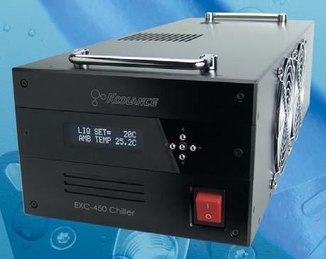
4 System Diagram Positioning the System Carrying Handles LED Display Panel Fill Port CAUTION: Always keep the chiller upright during operation. Additionally, THE UNIT MUST BE KEPT UPRIGHT FOR AT LEAST 24 HOURS BEFORE POWERING ON. This is to allow enough oil to reach the compressor. Powering-on the unit too early can permanently damage the compressor and is not covered by the product warranty. Control Panel The chiller must be run upright at all times. Upon arrival of this product via transport or courier shipping, it must be kept upright FOR AT LEAST 24 HOURS BEFORE BEING POWERED ON to allow enough oil to reach the compressor. Power Switch Condenser Fans Relay & Thermocouple Terminals (Optional) Reservoir Level Coolant Outlet Coolant Inlet Drain Plug OK NO NO External Fittings Install G 1/4 BSPP threaded fittings you have purchased into the Inlet and Outlet ports. It s recommended to hand-tighten all fittings to avoid damaging the cooling unit. Parallel threads seal at their o-ring. Do not use any plumber s tape or putty on the threads, which can interfere with the o-ring seal. Power Connection Leave the Drain plug installed. This is only opened when emptying coolant. 4 User Manual 5


. Squeeze the tube while pushing it firmly over the fitting. Tubing should completely cover the fitting or barb.")


.")


5 Cut tubing into two segments. You will need to connect each to the rear nozzles. Each hose connection will use a threaded compression ring or hose clamp to keep it secure. Be sure to thread the compression ring or hose clamp onto the hose before attaching it. Slowly fill the system with coolant. To maintain the product warranty, use only Koolance approved coolant. Many alternative liquids and additives can cause permanent damage to the cooling unit (through chemical reaction, corrosion, biological growth, thermal expansion, viscosity, etc.). Squeeze the tube while pushing it firmly over the fitting. Tubing should completely cover the fitting or barb. Replace the fill port on the reservoir. Do not overtighten the fill port. CAUTION: The chiller is specific to one input voltage and polarity direction. Supply only the proper input voltage and polarity, as labeled near the power terminals. Supplying the improper voltage or polarity can damage the unit and is not covered by the product warranty. Tighten the connection by sliding the compression nut down over the fitting and screwing securely. For hose barbs, use pliers to move it into the proper position before releasing. Coolant Filling and Powering-On EXC-450 requires a 24VDC, 230W power supply (not included). Connect wires to the positive + and negative - terminals, as labeled on the back of the unit. WARNING: Most coolants are electrically conductive. Use caution when filling the system, and keep all liquids away from electronics and power cables. Keep the primary AC power cable unplugged whenever filling or draining coolant. Power on the cooling unit. Set the pump to the highest speed setting until most of the air in the cooling loop has been pushed into the reservoir. Once this occurs, the liquid noise will drop. This process can take several minutes, depending on the filling technique and what s connected to the system. Once all devices (cold plates, fittings, etc.) have been connected with tubing, the system can be filled with coolant. The fill port is located on top of the system over the reservoir. Remove the large slot-headed screw with a screwdriver or large coin. During this process, components may need to be tilted gently to assist with air evacuation. The reservoir level will decrease during this procedure. Remove the fill port cap and add more liquid as needed. Maximum and minimum fill markings are provided on the back side of the unit to help maintain the coolant level. 6 User Manual 7
6 Display Panel The Koolance display panel allows control and monitoring of various aspects of the cooling unit. 5 buttons are used, with directional arrows to navigate or change settings, and a center button to select/exit. Navigate Up, Increase Setting TEMP SET CAUTION: This cooling system can chill liquid below the ambient air temperature, which may cause condensation to form on tubing and cold plates. It is highly recommended to keep the temperature at or above the ambient temperature. (See below for details.) On the main screen, hold for 3 seconds to change display units between C/ F and LPM/GPM. You can exit any menu and return to the main screen by holding for 2 seconds. To reset ALL settings to default, hold + for 3 seconds. Main Menu To enter the main menu, briefly press. The selected option will begin flashing. Use and to navigate this menu. Navigate Left TEMP SET: Temperature set-point adjustment ALARM SET: Alarm settings RELAY SET: Relay Trigger settings PUMP SET: Pump speed settings DISPLAY SET: LCD display settings Navigate Down, Decrease Setting Navigate Right Enter/Exit When in the top menu, press to enter one of the above categories. To exit from here, press. Under TEMP SET, you can select the active temperature sensor and set-point the chiller will try to follow. There are four temperature options to select from. Press and to scroll among these options: CAUTION: Do not use a temperature set-point that is below the coolant s freezing point. This may damage the cooling unit and is not covered by the product warranty. It is recommended to always keep the temperature set-point at or above ambient temperature. LIQ TEMP: Liquid temperature (Range: 1 to 50 C) EXT TEMP: Rear sensor, if attached (Range: 1 to 149 C) LIQ-AMB: Delta-T between liquid & ambient (Range: -50 to 50 C) EXT-AMB: Delta-T between rear sensor & ambient (Range: -50 to 50 C) The sensor currently displayed in this menu is what the chiller will follow. Only one can be active. Press to adjust the target temperature value using and. Below are some examples: LIQ TEMP= 28C Maintain coolant coming from the chiller at 28 C EXT TEMP= 50C Maintain the external sensor at 50 C (if attached) LIQ-AMB= -5C Maintain a difference between the liquid and ambient air of -5 C (keep liquid 5 C below ambient) EXT-AMB= 5C Maintain a difference between the external sensor and ambient air of +5 C (keep sensor 5ºC above ambient) External Sensor This unit provides a terminal on the rear for connecting a K-type thermocouple (not included) for external monitoring and temperature configuration. Press again to exit configuration of the sensor. Press to return to the previous menu. With these settings, it s possible to set the liquid temperature below the environmental air temperature. If liquid temperatures reach the ambient dew point, condensation (water droplets) can form on tubing and cold plates connected to the chiller. Unless condensation is prepared for, it is recommended to keep the chiller on LIQ- AMB with a minimum value of 0 C (which keeps liquid at ambient). 8 User Manual 8 User Manual 9
7 ALARM SET PUMP SET This menu affects when the built-in audio alarm will sound. Upon entering the alarm menu, the temperature delta-t value will flash. Press or to adjust this value. Press to accept and return to the previous menu. ALARM SET (TEMP SET) ± 5C WARNING: The cooling system s pump can not be run dry for any period of time. Never power-on the chiller without sufficient liquid in the reservoir. Dry-running (and thereby damaging the pump) is not covered under the Koolance product warranty. In the above example, the alarm will sound if the temperature exceeds a 5 C difference (+ or -) from the chiller s currently active temperature sensor (see TEMP SET ). The maximum delta-t setting range for the alarm is 49 C. The regular audio alarm is a repeating beep. If a steady alarm tone is heard, this indicates the relay has also been triggered (see RELAY SET ). NOTE: The alarm temperature must be at least 1 C (1-2 F) lower than the relay temperature. If an alarm temperature can not be increased, first increase the relay temperature. Likewise, if a relay temperature can not be decreased, first decrease the alarm temperature. The pump speed can be manually set from 1 (lowest) to 10 (highest): PUMP(1-10) 7LV : Pump Speed Level The pump speed level will flash. Press or to adjust. Press to return to the previous menu. DISPLAY SET The display settings configure which values you wish to appear on the front display and how they are shown: RELAY SET DISPLAY FIXED CYCLIC : Show 2 fixed values or cycle multiple values Rear terminals are provided for a temperatureconfigurable relay. Wires can be connected as normally-open (NO), or normally-closed (NC), labeled below the terminals. To adjust the relay trigger point, enter the RELAY SET menu. Press or to adjust this value. Press to accept and return to the previous menu. RELAY SET (TEMP SET) ± 40C In the above example, the relay will trigger if the temperature exceeds a 40 C difference (+ or -) from the chiller s currently active temperature sensor (see TEMP SET ). The maximum delta-t setting range for the relay is 50 C. NOTE: The relay temperature must be at least 1 C (1-2 F) higher than the alarm temperature. If an alarm temperature can not be increased, first increase the relay temperature. Likewise, if a relay temperature can not be decreased, first decrease the alarm temperature. The first option, FIXED, will flash. Press or to change between these options. Press to configure one of the selections, or press to exit. If FIXED is selected, two lines will be shown: LIQ SET EXT TEMP 20C : First line display option 21.4C : Second line display option The first line will flash. Press or to change what this line will display: LIQ SET : (Field varies) Shows current active sensor and user set-point AMB TEMP : Shows ambient air temperature LIQ TEMP : Shows reservoir liquid temperature EXT TEMP : Shows external sensor temperature (if connected) FAN : Shows condenser fan RPM PUMP : Shows pump impeller RPM FLOW : Shows liquid flow rate through the unit Press to move to line 2, and similarly use or to choose what will be displayed on the second line. Press again to exit. 10 User Manual 11
8 If CYCLIC is chosen from the DISPLAY SET menu, multiple values can be rotated through the front display. The first line will flash. Use and to navigate to other lines. Press to enable or disable each value. This will remove the asterisk, thereby hiding that line from being shown on the main screen: *LIQ SET : (Field varies) Show current active sensor and user set-point *AMB TEMP : Show ambient air temperature LIQ TEMP : Hide liquid temperature *EXT TEMP : Show external sensor temperature (if connected) FAN : Hide condenser fan RPM PUMP : Hide pump impeller RPM *FLOW : Show liquid flow rate through the unit Press to return to the previous menu, or press to exit DISPLAY SET. Troubleshooting We hope your Koolance system will provide you with years of reliable cooling performance. To help avoid unnecessary RMA issues, we have prepared this list of possible operational problems, and their most common solutions. 1. After filling the reservoir with coolant and turning on the system, there are no visible signs of liquid movement... Check the flow meter value (see DISPLAY SET ). If there is no detected flow immediately after filling the reservoir, or the flow rate is very low or periodic, this usually indicates the pump has not finished priming. Open the fill port on top of the chiller and temporarily set the pump speed to 10 (see PUMP SET ) to help push out the air. If possible while the pump is running, gently tilt your cold plates or other components connected to the chiller in various directions to assist with bleeding air from the cooling loop. If it becomes necessary to tilt the chiller to assist with priming, close the fill port and power-off the unit before doing so. 3. The temperature alarm sounds and I m not sure why... The offending temperature sensor and value will flash in the front display whenever an alarm sounds. Check that your currently selected temperature sensor and alarm are configured as desired (see TEMP SET and ALARM SET ). If you are certain the cooling system is working properly otherwise, try resetting all system settings by holding + for 3 seconds. 4. My system appears to be leaking fluid or water... Check that the fittings on the rear inlet/outlet and drain plug are securely tightened (by hand, not with tools). They are parallel type threads, so no plumber s tape or putty should be used or this can interfere with proper sealing. If during operation the outsides of your tubing or cold plates is wet, this can indicate condensation. The chiller temperature setting should not be lower than the ambient room air temperature. (See TEMP SET for recommendations.) 5. The front display is locked up or not responding. Reset all system settings by holding + for 3 seconds. After a reset, all configuration settings (temperature, alarm, fans, etc.) must be updated again. 12 User Manual 13
9 Limited Warranty Koolance Incorporated ( Koolance ) warrants each new Koolance liquid-cooled system ( the system ), against defects in materials or workmanship for a period of one year from the date of purchase, and agrees to repair or replace any defective Koolance system without charge. Shipping costs are non-refundable. This warranty is non-transferable. All warranty claims must be accompanied by the original proof of purchase. THIS WARRANTY DOES NOT COVER DAMAGE RESULTING FROM ACCIDENT, MISUSE OR ABUSE, LACK OF REASONABLE CARE, SHIPPING DAMAGE, MODIFICATIONS, THE AFFIXING OF ANY ATTACHMENT NOT PROVIDED WITH THE PRODUCT, LOSS OF PARTS, OR OPERATING COMPONENTS AT SPEEDS OR FUNCTIONS OTHER THAN THOSE SPECIFIED BY THEIR MANUFACTURERS. Use of unauthorized replacement parts or liquids will void this warranty. Koolance Incorporated will not pay for warranty service performed by a non-authorized repair or diagnostic service and will not reimburse the consumer for damage resulting from warranty service performed by a non-authorized repair service. No responsibility is assumed for any special incidental or consequential damages due to a defective Koolance product. In order to obtain warranty service, contact our RMA department for information. The product must be shipped postage prepaid to an authorized Koolance service location. It is suggested that, for your protection, you return shipments of product by insured mail, insurance prepaid. Damage occurring during shipment is not covered by this warranty. Shipping costs are non-refundable. No other warranty, written or oral, is authorized by Koolance Incorporated. Disclaimer IN NO EVENT SHALL KOOLANCE INCORPORATED OR ITS EMPLOYEES, AGENTS, SUPPLIERS, MANUFACTURERS, OR CONTRACTORS BE LIABLE FOR ANY DAMAGES OF ANY KIND OR CHARACTER, INCLUDING WITHOUT LIMITATION ANY COMPENSATORY, INCIDENTAL, DIRECT, INDIRECT, SPECIAL, PUNITIVE, OR CONSEQUENTIAL DAMAGES, LOSS OF USE, LOSS OF DATA, LOSS OF INCOME OR PROFIT, LOSS OF OR DAMAGE TO PERSONS OR PROPERTY, CLAIMS OF THIRD PARTIES, OR OTHER LOSSES OF ANY KIND OR CHARACTER, AND WHETHER OR NOT THE POSSIBILITY OF SUCH LOSS OR DAMAGE HAS BEEN NOTIFIED TO KOOLANCE INCORPORATED. 14
10 A newer version of this User Manual may exist. Please be sure to check our support page for the latest version of this guide: GENERAL PRECAUTION Please read this manual carefully before beginning the installation of your Koolance system. ABOUT SIGNS Throughout this document, critical information is highlighted in gray-colored boxes. The following symbols are intended to help prevent any situation which may cause personal injury and/or damage to equipment: WARNING: Indicates a potentially hazardous situation which, if not avoided, could result in personal injury or be life-threatening. CAUTION: Indicates a potentially hazardous situation which, if not avoided, may result in damage to equipment or property. PROHIBITED: Indicates a prohibited action. PROHIBITED USE This product is designed, developed and manufactured as contemplated for general use, including without limitation: general office use, personal use and household use, but is not designed, developed and manufactured as contemplated for use accompanying fatal risks or dangers that, unless extremely high safety is secured, could lead directly to death, personal injury, severe physical damage or other loss, including without limitation: nuclear power core control, airplane control, air traffic control, mass transport operation control, life support, or weapon launching control. If these products are used in such hazardous environments, Koolance Incorporated does not warrant them. TRADEMARKS The Koolance name and logo are trademarks or registered trademarks of Koolance, Inc. Other company and product names used in this publication are for identification purposes only and may be trademarks or registered trademarks of their respective companies. COPYRIGHT All rights reserved. Copyright (C) Koolance Incorporated. User Manual 1
11 WARNING: The Koolance liquid coolant contains chemicals which may be harmful or fatal if swallowed. KEEP THIS AND ALL DANGEROUS CHEMICALS OUT OF THE REACH OF CHILDREN. Please refer to the coolant MSDS available on our website: CAUTION: Always keep the chiller upright during operation. Additionally, THE UNIT MUST BE KEPT UPRIGHT FOR AT LEAST 24 HOURS BEFORE POWERING ON. This is to allow enough oil to reach the compressor. Powering-on the unit too early can permanently damage the compressor and is not covered by the product warranty. CAUTION: The chiller is specific to one input voltage. Supply only the proper input voltage, as labeled above the power terminals on the rear of the unit. Supplying the improper voltage can damage the unit and is not covered by the product warranty. CAUTION: This cooling system can chill liquid below the ambient air temperature, which may cause condensation to form on tubing and cold plates. It is highly recommended to keep the temperature at or above the ambient temperature. (See TEMP SET for details.) Table of Contents System Diagram... 4 Positioning the System... 5 External Fittings... 5 Coolant Filling and Powering-On... 7 Display Panel... 8 Temp Set... 9 Alarm Set Relay Set Pump Set Display Set Troubleshooting Limited Warranty Product Specifications CAUTION: Do not use a temperature set-point that is below the coolant s freezing point. This may damage the cooling unit and is not covered by the product warranty. It is recommended to always keep the temperature set-point at or above ambient temperature. KOOLANCE CONTACT INFORMATION Koolance Incorporated (USA) - Weight: 9kg (approx.) - Dimensions: 533 x 203 x 152mm (approx.) - Operating Temperature Range: Ambient 0-40 C, Water 0-40 C - Cooling Capacity: 450W ( C liquid/ambient - Refrigerant: R-134a - Pump: Koolance P/N PMP Power Input: 24 VDC, 230W - Power Consumption: 230W (approx.) Address: 2840 W. Valley Hwy. N., Auburn, WA, USA Telephone: Fax: Sales sales@koolance.com Tech tech@koolance.com Web: 2 User Manual 3
12 System Diagram Positioning the System Carrying Handles LED Display Panel Fill Port CAUTION: Always keep the chiller upright during operation. Additionally, THE UNIT MUST BE KEPT UPRIGHT FOR AT LEAST 24 HOURS BEFORE POWERING ON. This is to allow enough oil to reach the compressor. Powering-on the unit too early can permanently damage the compressor and is not covered by the product warranty. Control Panel The chiller must be run upright at all times. Upon arrival of this product via transport or courier shipping, it must be kept upright FOR AT LEAST 24 HOURS BEFORE BEING POWERED ON to allow enough oil to reach the compressor. Power Switch Condenser Fans Relay & Thermocouple Terminals (Optional) Reservoir Level Coolant Outlet Coolant Inlet Drain Plug OK NO NO External Fittings Install G 1/4 BSPP threaded fittings you have purchased into the Inlet and Outlet ports. It s recommended to hand-tighten all fittings to avoid damaging the cooling unit. Parallel threads seal at their o-ring. Do not use any plumber s tape or putty on the threads, which can interfere with the o-ring seal. Power Connection Leave the Drain plug installed. This is only opened when emptying coolant. 4 User Manual 5
13 Cut tubing into two segments. You will need to connect each to the rear nozzles. Each hose connection will use a threaded compression ring or hose clamp to keep it secure. Be sure to thread the compression ring or hose clamp onto the hose before attaching it. Slowly fill the system with coolant. To maintain the product warranty, use only Koolance approved coolant. Many alternative liquids and additives can cause permanent damage to the cooling unit (through chemical reaction, corrosion, biological growth, thermal expansion, viscosity, etc.). Squeeze the tube while pushing it firmly over the fitting. Tubing should completely cover the fitting or barb. Replace the fill port on the reservoir. Do not overtighten the fill port. CAUTION: The chiller is specific to one input voltage and polarity direction. Supply only the proper input voltage and polarity, as labeled near the power terminals. Supplying the improper voltage or polarity can damage the unit and is not covered by the product warranty. Tighten the connection by sliding the compression nut down over the fitting and screwing securely. For hose barbs, use pliers to move it into the proper position before releasing. Coolant Filling and Powering-On EXC-450 requires a 24VDC, 230W power supply (not included). Connect wires to the positive + and negative - terminals, as labeled on the back of the unit. WARNING: Most coolants are electrically conductive. Use caution when filling the system, and keep all liquids away from electronics and power cables. Keep the primary AC power cable unplugged whenever filling or draining coolant. Power on the cooling unit. Set the pump to the highest speed setting until most of the air in the cooling loop has been pushed into the reservoir. Once this occurs, the liquid noise will drop. This process can take several minutes, depending on the filling technique and what s connected to the system. Once all devices (cold plates, fittings, etc.) have been connected with tubing, the system can be filled with coolant. The fill port is located on top of the system over the reservoir. Remove the large slot-headed screw with a screwdriver or large coin. During this process, components may need to be tilted gently to assist with air evacuation. The reservoir level will decrease during this procedure. Remove the fill port cap and add more liquid as needed. Maximum and minimum fill markings are provided on the back side of the unit to help maintain the coolant level. 6 User Manual 7

 On the main screen, hold for 3 seconds to change display units between C/ F and LPM/GPM.")
14 Display Panel The Koolance display panel allows control and monitoring of various aspects of the cooling unit. 5 buttons are used, with directional arrows to navigate or change settings, and a center button to select/exit. Navigate Up, Increase Setting TEMP SET CAUTION: This cooling system can chill liquid below the ambient air temperature, which may cause condensation to form on tubing and cold plates. It is highly recommended to keep the temperature at or above the ambient temperature. (See below for details.) On the main screen, hold for 3 seconds to change display units between C/ F and LPM/GPM. You can exit any menu and return to the main screen by holding for 2 seconds. To reset ALL settings to default, hold + for 3 seconds. Main Menu To enter the main menu, briefly press. The selected option will begin flashing. Use and to navigate this menu. Navigate Left TEMP SET: Temperature set-point adjustment ALARM SET: Alarm settings RELAY SET: Relay Trigger settings PUMP SET: Pump speed settings DISPLAY SET: LCD display settings Navigate Down, Decrease Setting Navigate Right Enter/Exit When in the top menu, press to enter one of the above categories. To exit from here, press. Under TEMP SET, you can select the active temperature sensor and set-point the chiller will try to follow. There are four temperature options to select from. Press and to scroll among these options: CAUTION: Do not use a temperature set-point that is below the coolant s freezing point. This may damage the cooling unit and is not covered by the product warranty. It is recommended to always keep the temperature set-point at or above ambient temperature. LIQ TEMP: Liquid temperature (Range: 1 to 50 C) EXT TEMP: Rear sensor, if attached (Range: 1 to 149 C) LIQ-AMB: Delta-T between liquid & ambient (Range: -50 to 50 C) EXT-AMB: Delta-T between rear sensor & ambient (Range: -50 to 50 C) The sensor currently displayed in this menu is what the chiller will follow. Only one can be active. Press to adjust the target temperature value using and. Below are some examples: LIQ TEMP= 28C Maintain coolant coming from the chiller at 28 C EXT TEMP= 50C Maintain the external sensor at 50 C (if attached) LIQ-AMB= -5C Maintain a difference between the liquid and ambient air of -5 C (keep liquid 5 C below ambient) EXT-AMB= 5C Maintain a difference between the external sensor and ambient air of +5 C (keep sensor 5ºC above ambient) External Sensor This unit provides a terminal on the rear for connecting a K-type thermocouple (not included) for external monitoring and temperature configuration. Press again to exit configuration of the sensor. Press to return to the previous menu. With these settings, it s possible to set the liquid temperature below the environmental air temperature. If liquid temperatures reach the ambient dew point, condensation (water droplets) can form on tubing and cold plates connected to the chiller. Unless condensation is prepared for, it is recommended to keep the chiller on LIQ- AMB with a minimum value of 0 C (which keeps liquid at ambient). 8 User Manual 8 User Manual 9
 ± 5C WARNING: The cooling system s pump can not be run dry for any period of time.")
15 ALARM SET PUMP SET This menu affects when the built-in audio alarm will sound. Upon entering the alarm menu, the temperature delta-t value will flash. Press or to adjust this value. Press to accept and return to the previous menu. ALARM SET (TEMP SET) ± 5C WARNING: The cooling system s pump can not be run dry for any period of time. Never power-on the chiller without sufficient liquid in the reservoir. Dry-running (and thereby damaging the pump) is not covered under the Koolance product warranty. In the above example, the alarm will sound if the temperature exceeds a 5 C difference (+ or -) from the chiller s currently active temperature sensor (see TEMP SET ). The maximum delta-t setting range for the alarm is 49 C. The regular audio alarm is a repeating beep. If a steady alarm tone is heard, this indicates the relay has also been triggered (see RELAY SET ). NOTE: The alarm temperature must be at least 1 C (1-2 F) lower than the relay temperature. If an alarm temperature can not be increased, first increase the relay temperature. Likewise, if a relay temperature can not be decreased, first decrease the alarm temperature. The pump speed can be manually set from 1 (lowest) to 10 (highest): PUMP(1-10) 7LV : Pump Speed Level The pump speed level will flash. Press or to adjust. Press to return to the previous menu. DISPLAY SET The display settings configure which values you wish to appear on the front display and how they are shown: RELAY SET DISPLAY FIXED CYCLIC : Show 2 fixed values or cycle multiple values Rear terminals are provided for a temperatureconfigurable relay. Wires can be connected as normally-open (NO), or normally-closed (NC), labeled below the terminals. To adjust the relay trigger point, enter the RELAY SET menu. Press or to adjust this value. Press to accept and return to the previous menu. RELAY SET (TEMP SET) ± 40C In the above example, the relay will trigger if the temperature exceeds a 40 C difference (+ or -) from the chiller s currently active temperature sensor (see TEMP SET ). The maximum delta-t setting range for the relay is 50 C. NOTE: The relay temperature must be at least 1 C (1-2 F) higher than the alarm temperature. If an alarm temperature can not be increased, first increase the relay temperature. Likewise, if a relay temperature can not be decreased, first decrease the alarm temperature. The first option, FIXED, will flash. Press or to change between these options. Press to configure one of the selections, or press to exit. If FIXED is selected, two lines will be shown: LIQ SET EXT TEMP 20C : First line display option 21.4C : Second line display option The first line will flash. Press or to change what this line will display: LIQ SET : (Field varies) Shows current active sensor and user set-point AMB TEMP : Shows ambient air temperature LIQ TEMP : Shows reservoir liquid temperature EXT TEMP : Shows external sensor temperature (if connected) FAN : Shows condenser fan RPM PUMP : Shows pump impeller RPM FLOW : Shows liquid flow rate through the unit Press to move to line 2, and similarly use or to choose what will be displayed on the second line. Press again to exit. 10 User Manual 11
16 If CYCLIC is chosen from the DISPLAY SET menu, multiple values can be rotated through the front display. The first line will flash. Use and to navigate to other lines. Press to enable or disable each value. This will remove the asterisk, thereby hiding that line from being shown on the main screen: *LIQ SET : (Field varies) Show current active sensor and user set-point *AMB TEMP : Show ambient air temperature LIQ TEMP : Hide liquid temperature *EXT TEMP : Show external sensor temperature (if connected) FAN : Hide condenser fan RPM PUMP : Hide pump impeller RPM *FLOW : Show liquid flow rate through the unit Press to return to the previous menu, or press to exit DISPLAY SET. Troubleshooting We hope your Koolance system will provide you with years of reliable cooling performance. To help avoid unnecessary RMA issues, we have prepared this list of possible operational problems, and their most common solutions. 1. After filling the reservoir with coolant and turning on the system, there are no visible signs of liquid movement... Check the flow meter value (see DISPLAY SET ). If there is no detected flow immediately after filling the reservoir, or the flow rate is very low or periodic, this usually indicates the pump has not finished priming. Open the fill port on top of the chiller and temporarily set the pump speed to 10 (see PUMP SET ) to help push out the air. If possible while the pump is running, gently tilt your cold plates or other components connected to the chiller in various directions to assist with bleeding air from the cooling loop. If it becomes necessary to tilt the chiller to assist with priming, close the fill port and power-off the unit before doing so. 3. The temperature alarm sounds and I m not sure why... The offending temperature sensor and value will flash in the front display whenever an alarm sounds. Check that your currently selected temperature sensor and alarm are configured as desired (see TEMP SET and ALARM SET ). If you are certain the cooling system is working properly otherwise, try resetting all system settings by holding + for 3 seconds. 4. My system appears to be leaking fluid or water... Check that the fittings on the rear inlet/outlet and drain plug are securely tightened (by hand, not with tools). They are parallel type threads, so no plumber s tape or putty should be used or this can interfere with proper sealing. If during operation the outsides of your tubing or cold plates is wet, this can indicate condensation. The chiller temperature setting should not be lower than the ambient room air temperature. (See TEMP SET for recommendations.) 5. The front display is locked up or not responding. Reset all system settings by holding + for 3 seconds. After a reset, all configuration settings (temperature, alarm, fans, etc.) must be updated again. 12 User Manual 13
17 Limited Warranty Koolance Incorporated ( Koolance ) warrants each new Koolance liquid-cooled system ( the system ), against defects in materials or workmanship for a period of one year from the date of purchase, and agrees to repair or replace any defective Koolance system without charge. Shipping costs are non-refundable. This warranty is non-transferable. All warranty claims must be accompanied by the original proof of purchase. THIS WARRANTY DOES NOT COVER DAMAGE RESULTING FROM ACCIDENT, MISUSE OR ABUSE, LACK OF REASONABLE CARE, SHIPPING DAMAGE, MODIFICATIONS, THE AFFIXING OF ANY ATTACHMENT NOT PROVIDED WITH THE PRODUCT, LOSS OF PARTS, OR OPERATING COMPONENTS AT SPEEDS OR FUNCTIONS OTHER THAN THOSE SPECIFIED BY THEIR MANUFACTURERS. Use of unauthorized replacement parts or liquids will void this warranty. Koolance Incorporated will not pay for warranty service performed by a non-authorized repair or diagnostic service and will not reimburse the consumer for damage resulting from warranty service performed by a non-authorized repair service. No responsibility is assumed for any special incidental or consequential damages due to a defective Koolance product. In order to obtain warranty service, contact our RMA department for information. The product must be shipped postage prepaid to an authorized Koolance service location. It is suggested that, for your protection, you return shipments of product by insured mail, insurance prepaid. Damage occurring during shipment is not covered by this warranty. Shipping costs are non-refundable. No other warranty, written or oral, is authorized by Koolance Incorporated. Disclaimer IN NO EVENT SHALL KOOLANCE INCORPORATED OR ITS EMPLOYEES, AGENTS, SUPPLIERS, MANUFACTURERS, OR CONTRACTORS BE LIABLE FOR ANY DAMAGES OF ANY KIND OR CHARACTER, INCLUDING WITHOUT LIMITATION ANY COMPENSATORY, INCIDENTAL, DIRECT, INDIRECT, SPECIAL, PUNITIVE, OR CONSEQUENTIAL DAMAGES, LOSS OF USE, LOSS OF DATA, LOSS OF INCOME OR PROFIT, LOSS OF OR DAMAGE TO PERSONS OR PROPERTY, CLAIMS OF THIRD PARTIES, OR OTHER LOSSES OF ANY KIND OR CHARACTER, AND WHETHER OR NOT THE POSSIBILITY OF SUCH LOSS OR DAMAGE HAS BEEN NOTIFIED TO KOOLANCE INCORPORATED. 14
KD-CLN-LP200 Ultrasonic Vinyl Record Cleaner User s Manual English v1.2 Printed in Korea
 TM TM www.klaudio.com KD-CLN-LP200 Ultrasonic Vinyl Record Cleaner User s Manual English v1.2 Printed in Korea s are updated regularly. Please be sure to check our support page for a newer version of this
EXT-440 User s Manual
 Superior Liquid Cooling Systems www.koolance.com EXT-440 User s Manual English v1.0 ISO 9001 Printed in Korea Protected by U.S. Patents 6,313,990; 6,664,627; 7,167,366; 7,295,436 Other Technology Pending
ERM-3K4U User s Manual
 Superior Liquid Cooling Systems ERM-3K4U User s Manual English v1.00 Protected by U.S. Patents 6,664,627; 6,313,990; 6,234,240; 5,731,954 Other Technology Pending U.S. & World-Wide Patents This User Manual
User s Manual. PC & RP-1000 Based Systems. Superior Liquid Cooling Systems. English v1.02 ISO
 Superior Liquid Cooling Systems www.koolance.com PC4-1000 & RP-1000 Based Systems User s Manual English v1.02 ISO 9001 Printed in Korea Protected by U.S. Patents 6,664,627; 6,313,990; 6,234,240; 5,731,954
INSTALLER S & OWNER S MANUAL
 INSTALLER S & OWNER S MANUAL HVAC INSTALLER: PLEASE LEAVE MANUAL FOR HOMEOWNER DEH 3000R Part No. 4028407 Dehumidifier & Ventilation System Controller 4201 Lien Road, Madison, WI 53704 TOLL-FREE (800)-533-7533
INSTALLER S & OWNER S MANUAL
 INSTALLER S & OWNER S MANUAL HVAC INSTALLER: PLEASE LEAVE MANUAL FOR HOMEOWNER Part No. 4028539 Dehumidifier & Ventilation System Controller 4201 Lien Rd Madison, WI 53704 TOLL-FREE 1-800-533-7533 www.thermastor.com
MIGHTY PRO 1/4 HP CHILLER
 1 MIGHTY PRO 1/4 HP CHILLER FOR TANKS UP TO 170 GALLONS TOP QUALITY & HIGHLY EFFICIENT INTEGRATED DUAL STAGE THERMOSTAT 2 ASSEMBLY PARTS FRONT TOP VIEW BACK 3 SET UP INSTRUCTIONS 1. Remove chiller and
WARNING. Pro Pack Portable Spray Pack 3A1292C. Operation. Model 24F893 Maximum Working Pressure 12 psi (0.83 bar, MPa)
") Operation Pro Pack Portable Spray Pack - For use with Graco hand-held sprayers (except Fine-Finish sprayers) - - For portable spray applications of water-based and oil-based (mineral spirit-type) architectural
Operation Pro Pack Portable Spray Pack - For use with Graco hand-held sprayers (except Fine-Finish sprayers) - - For portable spray applications of water-based and oil-based (mineral spirit-type) architectural
Quest PowerHeat HFC 100 Pro
 Quest PowerHeat HFC 100 Pro Installation, Operation and Maintenance Instructions Read and Save These Instructions This manual is provided to acquaint you with the portable fan coil so that installation,
Owner s Manual Phoenix Aquadry TX 200
 4201 Lien Rd. Madison, WI 53704 Owner s Manual Phoenix Aquadry TX 200 Installation, Operation & Service Instructions Read and Save These Instructions The Phoenix Aquadry TX 200, like the TX 80, can be
User Manual. Humidity-Temperature Chart Recorder. Model RH520
 User Manual Humidity-Temperature Chart Recorder Model RH520 Introduction Congratulations on your purchase of the Extech RH520 Temperature + Humidity Chart Recorder. The RH520 measures and displays Temperature,
Prime Tower. Inline Chiller. Instructions for Models #2645,2646
 Prime Tower Inline Chiller Instructions for Models #2645,2646 Warning and Safety Instructions... Page 2 Chiller Installation... Page 3 Temperature Controller Programming... Page 5 Warranty... Page 6 JEE
P/N CC-100. Coolant Circulator. Operation manual
 P/N 4411-0019 CC-100 Coolant Circulator Operation manual Manual Version 1 Revision B July 1, 1998 Table of Contents Chapter 1 Introduction... 5 Description...5 Specifications...5 Chapter 2 Warnings...
Thermostat Series. Installation Manual TSTBM-RRS--TW-A Revised 02-13
 Installation Manual Thermostat Series TSTBM-RRS--TW-A Remote Temperature Sensor (Requires TSTBM3H2CPH6W-A) TSTBM-RRS--TW-A 2 TSTBM-RRS--TW-A Table Of Contents Table of Contents Thermostat Quick Reference...
User's Guide. Pinless Moisture Meter. Model MO257
 User's Guide Pinless Moisture Meter Model MO257 Introduction Congratulations on your purchase of the Extech MO257 Pinless Moisture Meter. The pinless moisture sensor monitors the moisture in wood and other
Environmental Monitoring SmartSlot Card
 Environmental Monitoring SmartSlot Card AP9612TH Installation and Quick Start Manual Contents Introduction............................. 1 Overview 1 Product inventory 1 Safety notice 2 Your inspection
AIC Brazed Plate Heat Exchanger Operating and Instruction Manual
 AIC Brazed Plate Heat Exchanger Operating and Instruction Manual Advanced Industrial Components Page 1 of 8 Customer Service Call: 1-888-738-1350 1.0 Installation 1.1 Mounting/support unit: a) On a shelf
Prime chiller. Inline Chiller. Instructions for Models #2645,2646
 Prime chiller Inline Chiller Instructions for Models #2645,2646 Warning and Safety Instructions... Page 2 Chiller Installation... Page 3 Temperature Controller Programming... Page 5 Warranty... Page 7
IMPORTANT SAFETY INSTRUCTIONS EC-AG1-25 EC-AG1, EC-AG2 SAVE THESE INSTRUCTIONS.
 IMPORTANT SAFETY INSTRUCTIONS 2 1. Read and Follow All Instructions 2. Read this manual completely before attempting installation. 3. All permanent electrical connections should be made by a qualified
Prime Chiller Mini-Chillers
 Prime Chiller Mini-Chillers Instructions for Model#2680, 2635 Warning and Safety Instructions... Page 2 Chiller Installation... Page 3 Programming Thermostat... Page 4 Warranty... Page 5 EMAIL:INFO@CURRENT-USA.COM
AC6 & AC8 HORIZONTAL SERIES Sealed Metallic Centrifugal Pumps Installation and Maintenance Instructions
 AC6 & AC8 HORIZONTAL SERIES Sealed Metallic Centrifugal Pumps Installation and Maintenance Instructions ASSEMBLY PUMPS WITH MOTORS 1. No assembly required. Unpack the pump and motor and examine for any
Quest Dry 150 Dual. quest Asset Protection and IAQ Solutions. Read and Save These Instructions. Installation, Operation and Maintenance Instructions
 Quest Dry 150 Dual Read and Save These Instructions This manual is provided to acquaint you with the dehumidifier so that installation, operation and maintenance can proceed successfully. Ultimate satisfaction
VX SERIES Wireless Thermostat with Occupancy Sensor
 VX SERIES Wireless Thermostat with Occupancy Sensor INSTRUCTION MANUAL Table of Contents Thermostat Installation... 7 Installing the Wireless Control Card...8 Mounting the thermostat to the wall...9 Thermostat
Quest Dry. Quest 110 Dual. Read and Save These Instructions. Installation, Operation and Maintenance Instructions
 Quest Dry Quest 110 Dual Read and Save These Instructions This manual is provided to acquaint you with the dehumidifier so that installation, operation and maintenance can proceed successfully. Ultimate
Projection Alarm Clock USER GUIDE
 Projection Alarm Clock USER GUIDE Jazwares, Inc. 2012 CONTENTS Please read the instructions along with the Alarm Clock carefully before you use it, so that you can operate it conveniently. WELCOME, Warnings
Digital Refrigerant System Analyzer. MAXMIN Psi kpa Bar MPa C F R TIME P T UNITS
 Digital Refrigerant System Analyzer INSTRUCTION MANUAL ENGLISH LOW START PRS T-LOW SUPERHEAT MAXMIN kpa Bar MPa R TIME P T HIGH END PRS T-HIGH SUBCOOL VAC 1-800-547-5740 Fax: (503) 643-6322 www.ueitest.com
DUAL VOLTAGE REFRIGERATORS 220/240 VOLTS AC AND 12/24 VOLTS DC INSTALLATION AND OWNER S MANUAL
 DUAL VOLTAGE REFRIGERATORS 220/240 VOLTS AC AND 12/24 VOLTS DC INSTALLATION AND OWNER S MANUAL Service Information If service or parts are required, contact the nearest Norcold Service Center. To find
Whynter Portable Ice Maker 33 lb capacity - White
 Whynter Portable Ice Maker 33 lb capacity - White Model # : IMC-330WS INSTRUCTION MANUAL Congratulations on your new Whynter product. To ensure proper operation, please read this Instruction Manual carefully
TUB AND SHOWER FAUCET
 ITEM #043465 TUB AND SHOWER FAUCET MODEL #F0E509CP Français / Español p. 4 Project Source ATTACH YOUR RECEIPT HERE Serial Number Purchase Date Questions, problems, missing parts? Before returning to your
VADA - Rain2Main Automatic Rainwater Controller
 PRODUCT OVERVIEW / APPLICATION The Vada Rain2Main is designed to select between stored rainwater (when available) and mains supply water, and send this water to your toilet cistern, washing machine, garden
Towel Warmer MAKE EVERYDAY A SPA DAY
 Towel Warmer MAKE EVERYDAY A SPA DAY TABLE OF CONTENTS Warnings and Cautions....1 FCC Information...4 Location of Parts and Controls...6 Set Up... 7 Using the Towel Warmer....8 Selecting the Timer...9
INSTRUCTION MANUAL C-4010 SCAN HERE
 FENIEX // 2018 // INSTRUCTION MANUAL Is this the latest version? SCAN HERE C-4010 INSTRUCTION MANUAL Feniex Product Copyrights This price List and the mentioned Feniex products include or describe copyrighted
CH750, CH751 & CH951 CHILLERS
 CH750, CH751 & CH951 CHILLERS Operator s & Installation Manual Release Date: April 19, 2002 Publication Number: 91256 Revision Date: March 25, 2014 Revision: F Visit the Cornelius web site at www.cornelius.com
MAYFIELD CEILING FAN LISTED E ITEM # MODEL #BTH44ABZC5C BTH44BNK5C Español p. 20 ATTACH YOUR RECEIPT HERE.
 Harbor Breeze is a registered trademark of LF, LLC. All Rights Reserved. ITEM #0331094 0331096 MAYFIELD CEILING FAN MODEL #BTH44ABZC5C BTH44BNK5C Español p. 20 ATTACH YOUR RECEIPT HERE Serial Number Purchase
Towel Warmer. Luxurious warmth for towels, robes and blankets
 Towel Warmer Luxurious warmth for towels, robes and blankets Table of contents Warnings and Cautions................................................... 2 Location of Controls......................................................
Power Pack Service Manual
 Power Pack Service Manual MMPP4301-EP MMPP4301 MMPP4301-PKG MMPP4302 MMPP4302-PKG MMPP4305-PKG MMPP4301-WC MMPP4302-WC MMPP4305-PKG-WC www.micromatic.com 1 TABLE OF CONTENTS Equipment Specifications...
ICE MAKER. Model: IM-101 INSTRUCTION MANUAL
 ICE MAKER Model: IM-101 INSTRUCTION MANUAL It is important that you read these instructions before using your portable ice maker and we strongly recommend that you keep them in a safe place for future
MCD. Corona Discharge Ozone Generators MANUFACTURED BY Bullock Lane San Luis Obispo, CA
 MCD Corona Discharge Ozone Generators MANUFACTURED BY 3428 Bullock Lane San Luis Obispo, CA 93401 4-0622 Copyright 2005 DEL Ozone, Inc. IMPORTANT SAFETY INSTRUCTIONS When installing and using DEL Models
CHILLER DADDY MODEL: CHL-501 Intended Use For: Residential & Office Water Chiller
 CHILLER DADDY MODEL: CHL-501 Intended Use For: Residential & Office Water Chiller OWNER S MANUAL TABLE OF CONTENTS 1. FOR YOUR SAFETY 2. LOCATION REQUIREMENTS 3. INSTALLATION PROCEDURES 4. PRESSURE LIMITER
Prime Chiller 1/10th HP Chiller
 Prime Chiller 1/10th HP Chiller Instructions for Model# 2635 Warning and Safety Instructions... Page 2 Chiller Installation... Page 3 Programming Thermostat... Page 4 Warranty... Page 5 EMAIL:INFO@CURRENT-USA.COM
SEABREEZE. SeaBreeze Rain Shower System Model #1086-CH Owner's Manual
 SEABREEZE SeaBreeze Rain Shower System Model #1086-CH Owner's Manual SeaBreeze Model #1086 Please Read The Following Instructions COMPLETELY Before Beginning! Our goal is to ensure your installation goes
Owner s Manual. Terpene Trap CF 1000
 Owner s Manual Terpene Trap CF 1000 IMPORTANT SAFETY INFORMATION: Please carefully read this manual before attempting to use your Terpene Trap. For your safety, comply with all safety instructions and
Owner s Manual Refrigerated Compressed Air Dryers Models F-200, 250, 300 & F350
 Owner s Manual Refrigerated Compressed Air Dryers Models F-200, 250, 300 & F350 Read carefully before attempting to assemble, install, operate or maintain the product described. Protect yourself and others
IMPORTANT INFORMATION - PLEASE READ CAREFULLY
 Honeywell Garrett Direct Fit Performance Intercooler 2015+ 3.5L / 2.7L Ford F150 EcoBoost Bill of Materials and Precautions Application: 2015+ Ford F150 3.5L / 2.7L Eco Boost Part Number: 870702-6001 Part
15Hp/20Hp Deluxe Compressor-Dryer System
 15Hp/20Hp Deluxe Compressor-Dryer System User Manual Installation Instructions Take your air system into the future with molecular sieve technology used in the Tsunami Regenerative Dryer compressed air
Panel Mounted Heat Exchangers by Dantherm, Inc.
 Panel Mounted Heat Exchangers by Dantherm, Inc. PRODUCT INFORMATION MANUAL C0028 003 Pinnacle OM Manual Rev AB Page 1 of 14 Dantherm, Inc. 110 Corporate Drive, Suite K Spartanburg, SC 29303 Tel # +1 864
Operator s Manual. The Quietek
 Operator s Manual The Quietek Congratulations! Congratulations on your purchase of the Quietek euthanization system. Please read this operator s manual which explains proper operation of the instrument.
Mixing Degas Vessel (MDV) EC-1, EC-2, EC-4, Total Eclipse 2 or 4, and TrioPure-25 or TrioPure-50
 EC-1, EC-2, EC-4, Total Eclipse 2 or 4, and TrioPure-25 or TrioPure-50") INSTALLATION MANUAL for MDV Mixing Degas Vessel (MDV) EC-1, EC-2, EC-4, Total Eclipse 2 or 4, and TrioPure-25 or TrioPure-50 MANUFACTURED BY 3428 Bullock Lane San Luis Obispo, CA 93401 800-676-1335 4-0635
INSTALLATION MANUAL for MDV Mixing Degas Vessel (MDV) EC-1, EC-2, EC-4, Total Eclipse 2 or 4, and TrioPure-25 or TrioPure-50 MANUFACTURED BY 3428 Bullock Lane San Luis Obispo, CA 93401 800-676-1335 4-0635
GRUNDFOS INSTRUCTIONS. Sololift2 C-3. Installation and operating instructions
 GRUNDFOS INSTRUCTIONS Sololift2 C-3 Installation and operating instructions English (US) English (US) Installation and operating instructions Original installation and operating instructions. CONTENTS
Beacon 800 Gas Monitor Operator s Manual
 Beacon 800 Gas Monitor Operator s Manual Part Number: 71-0037RK Revision: F Released: 4/18/17 www.rkiinstruments.com Product Warranty RKI Instruments, Inc. warrants gas alarm equipment sold by us to be
TRU-TEMP VALVE. Tru-Temp Pressure Balance 1/2" Rough-In Valve Owner's Manual 3001-RIV-PB-ORB 3001-RIV-PB-BN 3001-RIV-PB-CH 3003-RIV-PB-ORB
 TRU-TEMP VALVE 3001-RIV-PB-CH 3003-RIV-PB-CH Tru-Temp Pressure Balance 1/2" Rough-In Valve Owner's Manual 3001-RIV-PB-BN 3003-RIV-PB-BN 3001-RIV-PB-ORB 3003-RIV-PB-ORB Rough-In Valve Model #3001-RIV-PB
Power Pack Service Manual
 Power Pack Service Manual MMPP4301-EP MMPP4301 MMPP4301-WC MMPP4301-PKG MMPP4301-PKG-WC MMPP4302 MMPP4302-WC MMPP4302-PKG MMPP4302-PKG-WC MMPP4303-PKG MMPP4303-PKG-WC MMPP4303-PKG-3 MMPP4305-PKG MMPP4305-PKG-WC
WKS 4000 SERIES (USA only) --INSTALLATION INSTRUCTIONS--
 --INSTALLATION INSTRUCTIONS--") 8610 Production Avenue San Diego, California 92121 (858) 566-7465 Fax (858) 566-1943 WKS 4000 SERIES (USA only) --INSTALLATION INSTRUCTIONS-- Thank you for choosing a BREEZAIRE cooling unit. We believe
8610 Production Avenue San Diego, California 92121 (858) 566-7465 Fax (858) 566-1943 WKS 4000 SERIES (USA only) --INSTALLATION INSTRUCTIONS-- Thank you for choosing a BREEZAIRE cooling unit. We believe
INSTRUCTION MANUAL HS-229G
 INSTRUCTION MANUAL HS-229G 510977 STEP 1 - Where to Install the Thermostatic Steam Trap Determine where to install the thermostatic steam trap based on the following information. a. The trap should be
Air Cleaning Equipment, Inc. 303 N. Main St. Broadway, NC iers.com
 Read and Save These Instructions Horizon Galaxy - Installation and Operations Manual Air Cleaning Equipment, Inc. 303 N. Main St. Broadway, NC 27505 www.horizondehumidif iers.com 1 Safety Notes: The Horizon
Quest Dry 105, 155, and 205 Dual
 Quest Dry 105, 155, and 205 Dual Read and Save These Instructions This manual is provided to acquaint you with the dehumidifier so that installation, operation and maintenance can proceed successfully.
Ion Endeavor Pump Controller Digital Level Control with Pump Alternation and High Water Alarm
 Ion Endeavor Controller Digital Level Control with Alternation Page 1 of 8 General Overview The Ion Endeavor is a pump controller that senses a water level of up to 72", has a configurable water level/pump
Installation Instructions / Warranty. Starck 10111XX XX XX1
 Installation Instructions / Warranty Starck 10111XX1 10120XX1 10211XX1 90502203 1/2005 Starck single control lavatory faucet 10111XX1 Starck tall single control lavatory faucet 10120XX1 Starck single control
Chore-Tronics Load Cell Indicator
 Chore-Tronics Load Cell Indicator June 2008 CTB Inc. Warranty Load Cell Indicator CTB Inc. Warranty CTB Inc. warrants each new product manufactured by it to be free from defects in material or workmanship
Ion Genesis II Pump Controller Digital Level Control with Pump Alternation and High Water Alarm
 Page 1 of 8 General Overview Thank you for purchasing an Ion Genesis controller. Take the time to read the instructions carefully before using this appliance. We strongly recommend that you keep this instruction
OPERATION MANUAL. CLASSIC 10 and CLASSIC 18 SERIAL NUMBER FROM JANUARY 2009 (0109) TO PRESENT
 TO PRESENT") OPERATION MANUAL CLASSIC 10 and CLASSIC 18 SERIAL NUMBER FROM JANUARY 2009 (0109) TO PRESENT READ THIS MANUAL CAREFULLY FOR INSTRUCTIONS ON CORRECT INSTALLATION AND USAGE, AND READ ALL SAFEGUARDS SECCIÓN
OPERATION MANUAL CLASSIC 10 and CLASSIC 18 SERIAL NUMBER FROM JANUARY 2009 (0109) TO PRESENT READ THIS MANUAL CAREFULLY FOR INSTRUCTIONS ON CORRECT INSTALLATION AND USAGE, AND READ ALL SAFEGUARDS SECCIÓN
Operator s Manual. The Bullet Blender 50 BB50-AU, BB50-DX. Contents. Congratulations!
 Operator s Manual The Bullet Blender 50 BB50-AU, BB50-DX Congratulations! Congratulations on your purchase of a Bullet Blender 50 by Next Advance, Inc., for mixing, lysing, disrupting, and homogenizing
Blade Series Heat Exchanger Operation and Installation
 Blade Series Heat Exchanger Operation and Installation *IMPORTANT* For safe and satisfactory operation, please read the following instructions. Keep these instructions for future reference. Some information
Installation Instructions Model: EB Single-Lever Lavatory Faucet
 by Dawn Kitchen & Bath Products, Inc. 877-Dawn-USA dp@dawnusa.net www.dawnusa.net Installation Instructions Model: EB1359150 Single-Lever Lavatory Faucet TABLE OF CONTENTS Preparation Parts Installation
USER MANUAL. Bottled Water Dispenser SAVE FOR FUTURE USE. Model #
 Model # 900161: Page 1 USER MANUAL Bottled Water Dispenser Model # 900161 TO REDUCE THE RISK OF INJURY AND PROPERTY DAMAGE, USER MUST READ THIS MANUAL BEFORE ASSEMBLING, INSTALLING & OPERATING DISPENSER.
Ambient Weather RC-8487 ClearView Radio Controlled Travel Alarm Clock with Indoor Temperature User Manual
 Ambient Weather RC-8487 ClearView Radio Controlled Travel Alarm Clock with Indoor Temperature User Manual Table of Contents 1. Introduction... 1 2. Getting Started... 2 2.1 Display Features... 2 2.2 Parts
INSTRUCTION MANUAL P Heating and 1 Cooling
 REPLACEMENT COMPONENTS DIVISION CARRIER CORPORATION www.totaltouch.info Technical Support: 1-866-90TOUCH (1-866-908-6824) INSTRUCTION MANUAL P286-1200 2 Heating and 1 Cooling Physical Dimensions Case:
Whole House Filter Model: WH-LD
 INSTALLATION, OPERATION AND MAINTENANCE MANUAL Save manual for future reference Whole House Filter Model: WH-LD! WARNING Please read carefully before proceeding with installation. Your failure to follow
INSTALLATION AND OPERATION INSTRUCTIONS
 MODEL: RCT-MLT III INSTALLATION AND OPERATION INSTRUCTIONS INTRODUCTION IF YOU CANNOT READ OR UNDERSTAND THESE INSTALLATION INSTRUCTIONS DO NOT ATTEMPT TO INSTALL OR OPERATE This remote control system
Installation & Operating Instructions
 PREMIUM Installation & Operating Instructions AQP-20SIL Signature Filtered Water Cooler Premium Selection Congratulations on your purchase of a Aquaport Signature Filtered Water Cooler This unit is easy
Model NT20e Installation Guide
 Model NT20e Installation Guide Rev 1.4 Page 2 of 14 1. Preparing for Installation CAUTION Do not remove the NT20e from the Electro-static bag until instructed from this installation guide. The NT20e is
Inline Heater for Solvent or Gas. Installation and Operation Manual
 SH Series Inline Heater for Solvent or Gas Installation and Operation Manual This instruction manual explains the basic operation of the Process Technology inline solvent or gas heater. We recommend reading
PERFECT CHILL WINE CHILLER. USE AND CARE MANUAL MODEL Bottle
 PERFECT CHILL WINE CHILLER USE AND CARE MANUAL MODEL 88013 35 Bottle SAFETY INFORMATION------------------------------------------------------------ 2 WELCOME------------------------------------------------------------------------------------
WATLOW IND. WATROD Modular Duct Heater Installation & Maintenance Manual I&M NUMBER: Page: 1 Date:6/11/2008 Rev: 2
 I&M NUMBER: 316-42-15-1 Page: 1 _ Pre Installation Check to make sure that heater received is the same as that ordered. Elements may come in contact with each other during shipment. Minor adjustments to
Prime Chiller Modular Upgradable Chiller
 Prime Chiller Modular Upgradable Chiller Instructions for Models Single Stage Thermostat #2604, 2606 Dual Stage Thermostat #2614, 2616 Single Stage Thermostat w/ TXV #2626, 2627 Warning and Safety Instructions...
Installation & Maintenance Instructions. Smart Guard Ultra ZERO AIR LOSS CONDENSATE DRAIN 02/09
 Installation & Maintenance Instructions Smart Guard Ultra ZERO AIR LOSS CONDENSATE DRAIN 02/09 GENERAL OPERATION The Smart Guard Ultra is a zero-air-loss, electronic level sensing condensate drain. By
Radio Frequency Do s & Don ts
 Radio Frequency Do s & Don ts Please read before installing! Almost all of us have used a cordless phone, cellular phone, or FRS radios by now. They all work with the same principles as our wireless products
CH250 AND CH251 CHILLERS
 CH250 AND CH251 CHILLERS Operator s & Installation Manual Release Date: April 19, 2004 Publication Number: 620914801 Revision Date: May 15, 2015 Revision: G Visit the Cornelius web site at www.cornelius.com
POWER PACK SERVICE MANUAL
 POWER PACK SERVICE MANUAL MMPP4301-EP MMPP4301 MMPP4301-WC MMPP4301-PKG MMPP4301-PKG-WC MMPP4302 MMPP4302-WC MMPP4302-PKG MMPP4302-PKG-WC MMPP4303-PKG MMPP4303-PKG-WC MMPP4303-PKG-3 MMPP4305-PKG MMPP4305-PKG-WC
User's Guide. Pinless Moisture/Humidity Meter + IR. Model MO290
 User's Guide Pinless Moisture/Humidity Meter + IR Model MO290 Introduction Congratulations on your purchase of the Extech MO290 Pinless Moisture Meter with Patented Built-in IR Thermometer. Monitor moisture
OPERATING MANUAL. The Guardian Hand Held Security Metal Detector
 OPERATING MANUAL The Guardian Hand Held Security Metal Detector COMFORT GRIP OPERATOR DETECTION ALERTS Audio Alert High Pitch Sound Vibration Alert - Silent Operation LED Target Indicator - Red INTERFERENCE
User's Guide. Pinless Moisture/Humidity Meter with Memory + IR Thermometer. Model MO295
 User's Guide Pinless Moisture/Humidity Meter with Memory + IR Thermometer Model MO295 Introduction Congratulations on your purchase of the Extech MO295 Pinless Moisture Meter with Patented Built-in IR
Installation Manual. THM-0100 Setpoint Thermostat Version THM HBX Control Systems Inc.
 Installation Manual M-000 Setpoint Thermostat Version.04 M-000 HBX Control Systems Inc. TABLE OF CONTENTS Introduction Index Safety symbols and Warnings Index Receipt and Inspection Description Technical
This instruction manual explains the use of three models listed on the left.
 Semiconductor Manufacturing Gas Detector This instruction manual explains the use of three models listed on the left. Keep this Instruction Manual available for quick reference when needed. Read this Instruction
Battery Powered Actuator with Watering Timer RBC MVA
 Battery Powered Actuator with Watering Timer RBC MVA I N S T R U C T I O N M A N U A L TABLE OF CONTENTS 1. Introduction 1 2. About the RBC MVA battery operated timer 1 3. Component identification 1 4.
Battery Powered In-line Valve with Watering Timer RBC 7000
 Battery Powered In-line Valve with Watering Timer RBC 7000 I N S T R U C T I O N M A N U A L Table of contents 1. Introduction 1 2. About the RBC 7000 battery timer 1 3. Component identification 1 4. LCD
17 U.S. gallon portable low profile drain with electric pump
 Assembly and operation instructions 17 U.S. gallon portable low profile drain with electric pump Model 3669 Date of issue February 2018 Form number 404513 Version 2 Contents Safety...........................
Installation Manual. Detector Bases: PAD100-IB, PAD100-RB & PAD100-SB
 - + - + - + 1. Description This document provides instructions for mounting and wiring the Detector Bases PAD100-, PAD100-RB and PAD100-SB. The following detectors are compatible with Detector Bases PAD100-,
OUT TO WALLJACK. Input
 Innovative Technologies in Custom Electronic Design & Manufacturing Thank you for purchasing our Intermediate FreezeAlarm, model FA-I. The FreezeAlarm Intermediate model will automatically call up to three
SFD. Suburban Filter Dryer. User Manual Installation Instructions
 SFD Suburban Filter Dryer User Manual Installation Instructions Take your air system into the future with patented, molecular sieve technology used in the SFD regenerative cycle compressed air drying system.
IMPORTANT INFORMATION - PLEASE READ CAREFULLY
 Honeywell Garrett Direct Fit Performance Intercooler 2015+ 3.5L / 2.7L Ford F150 EcoBoost Bill of Materials and Precautions Application: 2015+ Ford F150 3.5L / 2.7L Eco Boost Part Number: 870702-6001 Part
SolarPRO CURVE HEATER OWNER S MANUAL
 SolarPRO CURVE HEATER OWNER S MANUAL MODEL 4721 ENGLISH IMPORTANT SAFETY RULES Read all instructions BEFORE assembling and using this product. KEEP THIS MANUAL. IMPORTANT DO NOT RETURN PRODUCT TO STORE
REMOTE FAUCET PUMP SYSTEM
 REMOTE FAUCET PUMP SYSTEM Use & Care Guide See Important Safeguards on Page 2 An exclamation point within an equilateral triangle is intended to alert user to the presence of important operating and maintenance
XC Portable Air Conditioning
 PORTABLE AIR CONDITIONERS XC Portable Air Conditioning XC-14A, XC-22A, XC-30A Models USER & INSTALLATION MANUAL www.xpcc.com 2013 Xtreme Power Conversion Corporation. All rights reserved. Table of Contents
OFFICE PRO 63 READ THIS MANUAL CAREFULLY FOR INSTRUCTIONS ON CORRECT INSTALLATION AND USAGE AND READ ALL SAFEGUARDS
 OPERATION MANUAL OFFICE PRO 63 READ THIS MANUAL CAREFULLY FOR INSTRUCTIONS ON CORRECT INSTALLATION AND USAGE AND READ ALL SAFEGUARDS SECCIÓN EN ESPAÑOL SECTION EN FRANÇAIS AVAILABLE AT WWW.MOVINCOOL.COM
High Temperature InfraRed Thermometer with Laser Pointer
 User s Manual High Temperature InfraRed Thermometer with Laser Pointer MODEL 42545A Introduction Congratulations on your purchase of the Model 42545A IR Thermometer. The 42545A is capable of non-contact
Famous Trails Anaheim, California
 Famous Trails Anaheim, California Phone (714) 701-9671 Fax (714) 701-9672 Toll Free: (877) 97SCOPE www.famoustrails.com MD9100 Metal Detector OWNER S MANUAL 1 CONTENTS Features... 3 Preparation.. 4 Assembling
CWR265SZ 26 Bottle Built-in Wine Cooler Owner s Manual
 CWR265SZ 26 Bottle Built-in Wine Cooler Owner s Manual This owner s manual provides instructions on safe installation use, and troubleshooting assistance. Please read it carefully and save it for reference
OWNERS MANUAL MODEL EXTERMINATOR VS900 C/R BLACK VAPOR CLEANING SYSTEM SAFETY INSTRUCTIONS OPERATIONS CARE AND MAINTENANCE TROUBLESHOOTING WARRANTY
 OWNERS MANUAL MODEL EXTERMINATOR VS900 C/R BLACK VAPOR CLEANING SYSTEM SAFETY INSTRUCTIONS OPERATIONS CARE AND MAINTENANCE TROUBLESHOOTING WARRANTY BEFORE USING THIS VAPOR CLEANING SYSTEM READ THESE INSTRUCTIONS
2-Port alarmcharge Hub - Manual
 Installation Manual 1. What s in the box 2. Fixture preparation 3. Mounting 4. Mechanical 5. Device power Operation Manual 6. Device connectors and connections 7. Alarming remote control 8. Safety 9. Warranty