(12) Patent Application Publication (10) Pub. No.: US 2005/ A1
|
|
|
- Ashlee Anthony
- 5 years ago
- Views:
Transcription
1 (19) United States US 2005O1612O2A1 (12) Patent Application Publication (10) Pub. No.: US 2005/ A1 Merkys et al. (43) Pub. Date: Jul. 28, 2005 (54) MICROCHANNEL CONDENSER ASSEMBLY (75) Inventors: Justin P. Merkys, Barrington, IL (US); Doug McAlpine, Bartlett, IL (US); Susan A. Seaman, Streamwood, IL (US); Norman E. Street, O'Fallon, MO (US) Correspondence Address: MICHAEL BEST & FRIEDRICH, LLP 100 E WISCONSNAVENUE MILWAUKEE, WI (US) (73) Assignee: Hussmann Corporation, Bridgeton, MO (US) (21) Appl. No.: 10/762,416 (22) Filed: Jan. 22, 2004 Publication Classification (51) (52) Int. Cl."... F28F 13/12 U.S. Cl /122 (57) ABSTRACT A condenser assembly adapted to condense an evaporated refrigerant for use in a retail Store refrigeration System. The condenser assembly includes at least one microchannel condenser coil including an inlet manifold and an outlet manifold. The inlet manifold includes an inlet port for receiving the refrigerant, and the outlet manifold includes an outlet port for discharging the refrigerant. The condenser assembly also includes a frame Supporting the at least one microchannel condenser coil.
2
3
4
5
6 Jul. 28, 2005 Sheet 5 of 12 US 2005/ A1
7 Patent Application Publication Jul. 28, 2005 Sheet 6 of 12 US 2005/ A1
8 Patent Application Publication Jul. 28, 2005 Sheet 7 of 12 US 2005/ A1
9
10
11
12
13 Patent Application Publication Jul. 28, 2005 Sheet 12 of 12 US 2005/ A1

14 US 2005/ A1 Jul. 28, 2005 MICROCHANNEL CONDENSER ASSEMBLY FIELD OF THE INVENTION This invention relates generally to condenser coils, and more particularly to condenser coils for use in retail Store refrigeration Systems. BACKGROUND OF THE INVENTION 0002 Typical retail store refrigeration systems often uti lize conventional fin-and-tube condenser coils to dissipate heat from refrigerant passing through the condenser coils. Usually, in large-scale retail Store refrigeration Systems, a Singular, oftentimes large, conventional fin-and-tube con denser coil is sized to dissipate, or reject, an amount of heat equal to the heat load of the refrigeration System. In other words, the Singular fin-and-tube condenser coil is sized to dissipate the amount of heat in the refrigerant that was absorbed in other portions of the refrigeration System Fin-and-tube condenser coils, such as those utilized in many retail Store refrigeration Systems, often display poor efficiencies in dissipating heat from the refrigerant passing through the coils. As a result, fin-and-tube condenser coils can be rather large for the amount of heat they can dissipate from the refrigerant. Further, the larger the condenser coil becomes, the more refrigerant used in the refrigeration System, thus effectively increasing potential damage to the environment by an accidental atmospheric release Usually, in large-scale retail store refrigeration Systems, the Single fin-and-tube condenser coil is positioned outside the retail Store, Such as on a rooftop, to allow heat transfer between the fin-and-tube condenser coil and the outside environment (i.e., to allow the heat in the refrigerant to dissipate into the outside environment). Further, a mechanical draft may be provided by a fan, for example, to air-cool the fin-and-tube condenser coil Another form of heat exchangers is the microchan nel coil. Currently, the only major application of microchan nel coils is in the automotive industry. In an example automotive application, microchannel coils may be used as a condenser and/or an evaporator in the air conditioning System of an automobile. A microchannel condenser coil, for example, in an automotive air conditioning System is typi cally located toward the front of the engine compartment, where Space to mount the condenser coil is limited. There fore, the microchannel condenser coil, which is much Smaller than a conventional fin-and-tube condenser coil that would otherwise be used in the automotive air conditioning system, is a suitable fit for use in an automobile. Prior to the present invention, the microchannel condenser coil has not been used in retail Store refrigeration Systems, in part, because of the high costs and difficulty that would be associated with manufacturing a microchannel condenser coil large enough to accommodate the heat load of the refrigeration System. SUMMARY OF THE INVENTION 0006 The present invention provides, in one aspect, a condenser assembly adapted to condense a refrigerant for use in a retail Store refrigeration System. The condenser assembly includes at least one microchannel condenser coil including an inlet manifold and an outlet manifold. The inlet manifold has an inlet port for receiving the refrigerant, and the outlet manifold has an outlet port for discharging the refrigerant. The condenser assembly also includes a frame Supporting the condenser coil The present invention provides, in another aspect, a condenser assembly adapted to condense a refrigerant for use in a retail Store refrigeration System. The condenser assembly includes a first microchannel condenser coil con figured Such that the refrigerant makes at least one pass therethrough, and a Second microchannel condenser coil fluidly connected with the first microchannel condenser coil. The Second microchannel condenser coil is configured Such that the refrigerant makes at least one pass through the Second microchannel condenser coil after making at least one pass through the first microchannel condenser coil. The condenser assembly also includes a frame Supporting the first and Second microchannel condenser coils The present invention provides, in yet another aspect, a condenser assembly adapted to condense a refrig erant for use in a retail Store refrigeration System. The condenser assembly includes a first microchannel condenser coil configured Such that the refrigerant makes at least one pass therethrough, and a Second microchannel condenser coil configured Such that the refrigerant makes at least one pass therethrough. The condenser assembly also includes an inlet header fluidly connected with the first and second microchannel condenser coils. The inlet header is configured to deliver the refrigerant to the first and Second microchan nel condenser coils. The condenser assembly further includes an outlet header fluidly connected with the first and second microchannel condenser coils. The outlet header is config ured to receive refrigerant from the first and Second micro channel condenser coils. The first and Second microchannel condenser coils are connected to receive and deliver refrig erant in a parallel relationship between the inlet and outlet headers. The condenser assembly also includes a frame Supporting the first and Second microchannel condenser coils The present invention provides, in a further aspect, a method of assembling a condenser assembly adapted to condense a refrigerant for use in a retail Store refrigeration System. The method includes providing a first microchannel condenser coil configured Such that the refrigerant makes at least one pass therethrough, fluidly connecting the first microchannel condenser coil to a Second microchannel condenser coil configured Such that the refrigerant makes at least one pass through the Second microchannel condenser after making at least one pass through the first microchannel condenser coil, and Supporting the first and Second micro channel condenser coils with a frame The present invention provides, in another aspect, a method of assembling a condenser assembly adapted to condense a refrigerant for use in a retail Store refrigeration System. The method includes providing a first microchannel condenser coil configured Such that the refrigerant makes at least one pass therethrough and a Second microchannel condenser coil configured Such that the refrigerant makes at least one pass therethrough. The method also includes fluidly connecting an inlet header to the first and Second microchannel condenser coils. The inlet header is configured to deliver the refrigerant to the first and Second microchan nel condenser coils. The method further includes fluidly

15 US 2005/ A1 Jul. 28, 2005 connecting an outlet header to the first and Second micro channel condenser coils. The outlet header is configured to receive the refrigerant from the first and Second microchan nel condenser coils. The first and Second microchannel condenser coils are connected to receive and deliver refrig erant in a parallel relationship between the inlet and outlet headers. Also, the method includes Supporting the first and Second microchannel condenser coils with a frame Other features and aspects of the present invention will become apparent to those skilled in the art upon review of the following detailed description, claims and drawings. BRIEF DESCRIPTION OF THE DRAWINGS In the drawings, wherein like reference numerals indicate like parts: 0013 FIG. 1 is a perspective view of a first construction of a condenser assembly of the present invention FIG. 2 is an enlarged perspective view of a first microchannel condenser coil of the condenser assembly of FIG FIG. 3a is a partial section view of the first microchannel condenser coil of FIG. 2, exposing multiple microchannels FIG. 3b is a broken view of the first microchannel condenser coil of FIG FIG. 4 is a perspective view of a second construc tion of a condenser assembly of the present invention FIG. 5 is a perspective view of a condensing unit including the condenser assembly of FIG. 1 and a compres SO FIG. 6a is a perspective view of a second micro channel condenser coil that may be utilized in a condenser assembly of the present invention FIG. 6b is a perspective view of a third micro channel condenser coil that may be utilized in a condenser assembly of the present invention FIG. 7a is a schematic view of multiple micro channel condenser coils arranged as a multiple row assem bly, illustrating the multiple coils in a Series arrangement FIG. 7b is a schematic view of multiple micro channel condenser coils arranged as a multiple row assem bly, illustrating the multiple coils in a parallel arrangement FIG. 8a is a schematic view of multiple micro channel condenser coils arranged in a single row assembly, illustrating the multiple coils in a Series arrangement FIG. 8b is a schematic view of multiple micro channel condenser coils arranged in a single row assembly, illustrating the multiple coils in a parallel arrangement FIG. 9a is a schematic view of multiple coil assemblies in a Series configuration with an inlet header and an outlet header FIG. 9b is a schematic view of multiple coil assemblies in a parallel configuration with an inlet header and an outlet header FIG. 10 is a perspective view of a third construc tion of a condenser assembly of the present invention FIG. 11 is a perspective view of a fourth construc tion of a condenser assembly of the present invention FIG. 12 is a perspective view of a fifth construction of a condenser assembly of the present invention Before any features of the invention are explained in detail, it is to be understood that the invention is not limited in its application to the details of construction and the arrangements of components Set forth in the following description or illustrated in the drawings. The invention is capable of other embodiments and of being practiced or of being carried out in various ways. Also, it is to be understood that the phraseology and terminology used herein is for the purpose of description and should not be regarded as limited. DETAILED DESCRIPTION With reference to FIG. 1, a first configuration of a condenser assembly 10 is shown. The condenser assembly 10 may be used in a large-scale retail Store refrigeration System, Such as that found in many large grocery Stores or Supermarkets. In Such a refrigeration System, the condenser assembly 10 may be positioned outside the retail store, such as on the rooftop of the store, to allow heat transfer from the condenser assembly 10 to the outside environment. The role of the condenser assembly 10 in the refrigeration system is to receive compressed, gaseous refrigerant from one or more compressors (not shown), condense the gaseous refrigerant back into its liquid form, and discharge the compressed, liquid refrigerant to one or more evaporators (not shown) located inside the Store. The liquid refrigerant is evaporated when it is passed through the evaporators, and the gaseous refrigerant is drawn into the one or more compressors for re-processing into the refrigeration System. 0032) Refrigerant-22, or R-22, in addition to anyhy drous ammonia, for example, may be used in Such a refrig eration System to provide Sufficient cooling to the refrigera tion System. If R-22 is used as the refrigerant of choice, the components of the refrigeration System in contact with the R-22 may be made from copper, aluminum, or Steel, among other materials. However, as understood by those skilled in the art, if anyhydrous ammonia is used as the refrigerant of choice, copper components of the refrigeration System in contact with the anyhydrous ammonia may corrode. Alter natively, other refrigerants (including both two-phase and Single-phase refrigerants or coolants) may be used with the condenser assembly In addition to retail store refrigeration systems, the condenser assembly 10 may also be used in various process industries, where the condenser assembly 10 may be a portion of a fluid cooling System using a single-phase coolant (e.g., glycol). In Such an application, the role of the condenser assembly 10 the fluid cooling System is to receive heated liquid coolant from one or more heat Sources (e.g., a pump or an engine, not shown), cool the heated liquid, and discharge the cooled liquid coolant to the one or more heat Sources. The cooled liquid coolant is again heated when it is put in thermal contact with the one or more heat Sources, and the heated gaseous coolant is routed by a pump or compres Sors for re-processing into the fluid cooling System In the illustrated construction of FIG. 1, the con denser assembly 10 includes two microchannel condenser coils 14a, 14b being supported by a frame 18. The frame 18
. As shown in FIGS.")
16 US 2005/ A1 Jul. 28, 2005 may be a freestanding structure as shown in FIG. 1. How ever, the frame 18 may comprise any number of different designs other than that shown in FIG. 1. As such, the illustrated frame 18 of FIG. 1 is intended for illustrative purposes only. 0035). As shown in FIGS. 3a-3b, each microchannel condenser coil 14a, 14b includes an inlet manifold 22a, 22b and an outlet manifold 26a, 26b fluidly connected by a plurality of flat tubes 30. The inlet manifold 22a, 22b includes an inlet port 34a, 34b for receiving refrigerant, and the outlet manifold 26a, 26b includes an outlet port 38a, 38b for discharging the refrigerant. One or more baffles (not shown) may be placed in the inlet manifold 22a, 22b and/or the outlet manifold 26a, 26b to cause the refrigerant to make multiple passes through the flat tubes 30 for enhanced cooling of the refrigerant. 0036) The flat tubes 30 may be formed to include mul tiple internal passageways, or microchannels 42, that are much Smaller in size than the internal passageway of the coil in a conventional fin-and-tube condenser coil. The micro channels 42 allow for more efficient heat transfer between the airflow passing over the flat tubes 30 and the refrigerant carried within the microchannels 42, compared to the air flow passing over the coil of the conventional fin-and-tube condenser coil. In the illustrated construction, the micro channels 42 each are configured with a rectangular cross section, although other constructions of the flat tubes 30 may have passageways of other cross-sections. The flat tubes 30 are separated into about 10 to 15 microchannels 42, with each microchannel 42 being about 1.5 mm in height and about 1.5 mm in width, compared to a diameter of about 9.5 mm (%") to 12.7 mm (%") for the internal passageway of a coil in a conventional fin-and-tube condenser coil. However, in other constructions of the flat tubes 30, the microchannels 42 may be as small as 0.5 mm by 0.5 mm, or as large as 4 mm by 4 mm The flat tubes 30 may also be made from extruded aluminum to enhance the heat transfer capabilities of the flat tubes 30. In the illustrated construction, the flat tubes 30 are about 22 mm wide. However, in other constructions, the flat tubes 30 may be as wide as 26 mm, or as narrow as 18 mm. Further, the spacing between adjacent flat tubes 30 may be about 9.5 mm. However, in other constructions, the Spacing between adjacent flat tubes 30 may be as much as 16 mm, or as little as 3 mm As shown in FIG. 3b, each microchannel con denser coil 14a, 14b includes a plurality of fins 46 coupled to and positioned along the flat tubes 30. The fins 46 are generally arranged in a Zig-Zag pattern between adjacent flat tubes 30. In the illustrated construction, the fin density mesured along the length of the flat tubes 30 is between 12 and 24 fins per inch. However, in other constructions of the microchannel condenser coils 14a, 14b, the fin density may be slightly less than 12 fins per inch or more than 24 fins per inch. Generally, the fins 46 aid in the heat transfer between the airflow passing through the microchannel condenser coils 14a, 14b and the refrigerant carried by the microchan nels. The fins 46 may also include a plurality of louvers formed therein to provide additional heat transfer area. The increased efficiency of the microchannel condenser coils 14a, 14b is due in part to Such a high fin density, compared to the fin density of 2 to 4 fins per inch of a conventional fin-and-tube condenser coil The increased efficiency of the microchannel con denser coils 14a, 14b, compared to a conventional fin-and tube condenser coil, allows the microchannel condenser coils 14a, 14b to be physically much smaller than the fin-and-tube condenser coil. As a result, the microchannel condenser coils 14a, 14b are not nearly as tall, and are not nearly as wide as a conventional fin-and-tube condenser coil The microchannel condenser coils 14a, 14b are attractive for use with large-scale refrigeration Systems for these and other reasons. Since the microchannel condenser coils 14a, 14b are much Smaller than conventional fin-and tube condenser coils, the microchannel condenser coils 14a, 14b may occupy less space on the rooftops of the retail Stores in which they are installed. As a result, the micro channel condenser coils 14a, 14b are more aesthetically appealing from an outside perspective of the Store Since the microchannel condenser coils 14a, 14b are much Smaller than conventional fin-and-tube condenser coils, the microchannel condenser coils 14a, 14b may also contain less refrigerant compared to the conventional fin and-tube condenser coils. Further, less refrigerant may be required to be contained within the entire refrigeration System, therefore effectively decreasing potential damage to the environment by an accidental atmospheric release. Also, as a result of being able to decrease the amount of refrigerant in the refrigeration System, the retail Stores may See an energy Savings, since the compressor(s) may expend less energy to compress the decreased amount of refrigerant in the refrigeration System The condenser assembly 10 also includes fans 50 coupled to the microchannel condenser coils 14a, 14b to provide an airflow through the coils 14a, 14b. As shown in FIGS. 1 and 2, each microchannel condenser coil 14a, 14b includes two fans 50 mounted thereon. Alternatively, cen trifugal blowers (not shown) may be used in place of the fans 50 or in combination with the fans 50. The fans 50 are supported in a fan shroud 54, which guides the airflow generated by the fans 50 through the microchannel con denser coils 14a, 14b, and helps distribute the airflow amongst the face of each condenser coil 14a, 14b. In a preferred construction of the condenser assembly 10, the fans 50 may be low-noise fans, like the SWEPTWINGTM fans available from Revcor, Inc. of Carpentersville, Ill. to help decrease noise emissions from the condenser assembly 10. In other constructions of the condenser assembly 10, more or less than two fans 50 may be used for each condenser coil 14a, 14b to generate the airflow through the condenser coil 14a, 14b. Also, the fans 50 and/or the shroud 54 may comprise any number of designs different than that shown in FIGS FIG. 2 illustrates the shroud 54 Supporting an electric motor 58 for driving one of the fans 50. The electric motor 58 may be configured to operate using either an AC or DC power source. Further, the electric motor 58 may be electrically connected to a controller (not shown) that Selec tively activates the electric motor 58 to drive the fan 50 depending on any number of conditions monitored by the controller. For example, the fans 50 may be cycled on and off to either increase or decrease the heat transfer capability of the condenser coils 14a, 14b. In one manner of operating the fans 50, the fans 50 may be turned off during the

17 US 2005/ A1 Jul. 28, 2005 nighttime, when the ambient temperature around the con denser assembly 10 is typically less than during the daytime. In another manner of operating the fans 50, the controller may receive a Signal from a pressure Sensor that is in communication with one or both of the condenser coils 14a, 14b that is proportional to the pressure in the coils 14a, 14b. A measured pressure greater than Some pre-determined threshold pressure may trigger the controller to activate the electric motors 58 to drive the fans 50 to provide additional heat transfer capability to the coils 14a, 14b. Likewise, a measured pressure less than Some pre-determined threshold pressure may trigger the controller to deactivate the electric motors 58 to stop the fans FIG. 1 illustrates two microchannel condenser coils 14a, 14b fluidly connected with the refrigeration sys tem in a Series arrangement. The inlet port 34a of a first microchannel condenser coil 14a is shown coupled to an inlet header 59, whereby compressed, gaseous refrigerant is pumped to the first microchannel condenser coil 14a via the inlet header 59. In the illustrated construction, the inlet header 59 is coupled to the inlet port 34a by a brazing or welding process. Such a brazing or welding process pro vides a Substantially fluid-tight connection between the inlet header 59 and the inlet port 34a. However, other construc tions of the condenser assembly 10 may utilize some sort of fluid-tight releasable couplings to allow Serviceability of the coils 14a, 14b The outlet port 38a of the first microchannel con denser coil 14a is shown coupled to an inlet port 34b of a Second microchannel condenser coil 14b via a connecting conduit 60. In the illustrated construction, the outlet port 38a of the first microchannel condenser coil 14a is coupled to the connecting conduit 60 by a brazing or welding process, and the inlet port 34b of the second microchannel condenser coil 14b is also coupled the connecting conduit 60 by a brazing or welding process. AS previously Stated, Such a brazing or welding process provides a Substantially fluid-tight connec tion between the outlet port 38a of the first microchannel condenser coil 14a and the inlet port 34b of the second microchannel condenser coil 14b. However, other construc tions of the condenser assembly 10 may utilize some sort of permanent or releasable fluid-tight couplings. 0046) The outlet port 38b of the second microchannel condenser coil 14b is shown coupled to an outlet header 61, whereby compressed, Substantially liquefied refrigerant is discharged from the Second microchannel condenser coil 14b to the outlet header 61 for transporting the liquid refrigerant to a receiver (not shown) or other component in the refrigeration System. Further, in the illustrated construc tion, the outlet port 38b of the second microchannel con denser coil 14b is coupled to the outlet header 61 by a brazing or welding process to provide a Substantially fluid tight connection between the outlet port 38b of the second microchannel condenser coil 14b and the outlet header 61. However, other constructions of the condenser assembly 10 may utilize Some Sort of permanent or releasable fluid-tight couplings During operation of the refrigeration system utiliz ing the condenser assembly 10 of FIG. 1, the compressed, gaseous refrigerant is pumped into the first microchannel condenser coil 14a, where the heat transfer between the airflow passing through the condenser coil 14a and the refrigerant causes the gaseous refrigerant to at least partially condense as the refrigerant passes through the flat tubes 30. If baffles are not placed in either of the inlet or outlet manifolds 22a, 26a of the first microchannel condenser coil 14a, the refrigerant will make one pass from the inlet manifold 22a to the outlet manifold 26a before being discharged from the first microchannel condenser coil 14a. Further, the fans 50 may be activated to provide and/or enhance the airflow through the first microchannel con denser coil 14a to further enhance cooling of the refrigerant Since the condenser coils 14a, 14b are connected in a Series arrangement, the refrigerant is passed from the first microchannel condenser coil 14a to the Second microchan nel condenser coil 14b. If only a portion of the compressed, gaseous refrigerant is condensed in the first microchannel condenser coil 14a, then the remaining portion is condensed in the second microchannel condenser coil 14b. Like the first microchannel condenser coil 14a, if baffles are not placed in either of the inlet or outlet manifolds 22b, 26b of the second microchannel condenser coil 14b, the refrigerant will make one pass from the inlet manifold 22b to the outlet manifold 26b before being discharged from the Second microchannel condenser coil 14b. Further, the fans 50 may be activated to provide and/or enhance the airflow through the Second microchannel condenser coil 14b to further enhance cooling of the refrigerant FIG. 4 illustrates a condenser assembly 62 having two microchannel condenser coils 64a, 64b fluidly con nected with the refrigeration System in a parallel arrange ment. The frame 18 illustrated in FIG. 4 is substantially the same as that shown in FIG. 1, the particular design of which is for illustrative purposes only and will not be further discussed. The fans 50 and the fan shrouds 54 are also substantially the same as that shown in FIG. 1, and will not be further discussed. Inlet ports 66a, 66b of the first and Second microchannel condenser coils 64a, 64b are shown extending from inlet manifolds 70a, 70b and coupled to an inlet header 74, whereby compressed, gaseous refrigerant is pumped to the first and Second microchannel condenser coils 64a, 64b via the inlet header 74. In the illustrated construc tion, the inlet header 74 is coupled to the inlet ports 66a, 66b of the first and Second microchannel condenser coils 64a, 64b by a brazing or welding process to provide a Substan tially fluid-tight connection between the inlet header 74 and the inlet ports 66a, 66b. However, other constructions of the condenser assembly 62 may utilize Some Sort of permanent or releasable fluid-tight couplings In addition, orifice buttoning may be used in the condenser assembly 62 to facilitate a Substantially equal distribution of refrigerant to the coils 64a, 64b along the inlet header 74. This may be accomplished by varying the flow space through the inlet ports 66a, 66b of the coils 64a, 64b. In the illustrated construction of FIG. 4, coil 64b is located downstream of coil 64a. Furthermore, to maintain a substantially similar flow rate of refrigerant through both of the coils 64a, 64b, the inlet port 66a of coil 64a may be smaller than the inlet port 66b of coil 64b to accommodate for the pressure drop between the coils 64a, 64b. However, in other constructions of the condenser assembly 62, other restricting devices (not shown) may be positioned in the inlet ports 66a, 66b to provide a varying flow space rather than varying the size of the inlet ports 66a, 66b.
 Outlet ports 78a, 78b of the first and second microchannel condenser coils 64a, 64b are shown extending from outlet manifolds 82a, 82b coupled to an outlet header 86, whereby")
18 US 2005/ A1 Jul. 28, ) Outlet ports 78a, 78b of the first and second microchannel condenser coils 64a, 64b are shown extending from outlet manifolds 82a, 82b coupled to an outlet header 86, whereby compressed, liquid refrigerant is discharged from the first and Second microchannel condenser coils 64a, 64b via the outlet header 86. In the illustrated construction, the outlet header 86 is coupled to the outlet ports 78a, 78b of the first and Second microchannel condenser coils 64a, 64b by a brazing or welding process to provide a Substan tially fluid-tight connection between the outlet header 86 and the outlet ports 78a, 78b. However, other constructions of the condenser assembly 62 may utilize Some Sort of perma nent or releasable fluid-tight couplings In some constructions of the condenser assembly 62, the outlet header 86 may be configured to be used as a receiver for the liquid refrigerant condensed by the micro channel condenser coils 64a, 64b (see FIG. 10). The receiver is typically sized to be able to hold all of the refrigerant in the System in a condensed form. One or more liquid refrigerant lines may therefore fluidly connect the receiver and the one or more evaporators in the refrigeration System. By configuring the outlet header 86 to also act as the liquid refrigerant receiver, a dedicated Separate receiver tank (not shown) is not required in the refrigeration System. This allows a sizable component, in addition to the piping asso ciated there with, to be eliminated from the refrigeration System. Additional benefits Such as those outlined above may be realized by reducing the amount of refrigerant in the refrigeration System Also, in the illustrated construction, the inlet ports 66a, 66b extend substantially transversely from the inlet manifolds 70a, 70b, and the outlet ports 78a, 78b extend substantially transversely from the outlet manifolds 82a, 82b to fluidly connect with the inlet and outlet headers 74, 86. However, in other constructions of the condenser assembly 62, the inlet ports 66a, 66b and the outlet ports 78a, 78b may extend from the respective inlet manifolds 70a, 70b and the outlet manifolds 82a, 82b as shown in FIG. 1, and utilize additional intermediate piping to fluidly connect the inlet ports 66a, 66b with the inlet header 74 and the outlet ports 78a, 78b with the outlet header During operation of the refrigeration system utiliz ing the condenser assembly 62 of FIG. 4, the compressed, gaseous refrigerant is pumped through the inlet header 74, where the Some of the gaseous refrigerant enters the first microchannel condenser coil 64a and the remaining gaseous refrigerant enters the Second microchannel condenser coil 64b. Heat transfer between the airflow passing through the condenser coils 64a, 64b and the refrigerant causes the gaseous refrigerant to condense as the refrigerant passes through the flat tubes 30. If baffles are not placed in either of the inlet manifold 70a or the outlet manifold 82a of the first microchannel condenser coil 64a, the refrigerant will make one pass from the inlet manifold 70a to the outlet manifold 82a before being discharged from the first micro channel condenser coil 64a to the outlet header 86. Further, the fans 50 may be activated to provide and/or enhance the airflow through the first microchannel condenser coil 64a to further enhance cooling of the refrigerant Since the condenser coils 64a, 64b are connected with the refrigeration System in a parallel arrangement, and if baffles are not placed in either of the inlet manifold 70b or the outlet manifold 82b of the second microchannel con denser coil 64b, the refrigerant will make one pass from the inlet manifold 70b to the outlet manifold 82b before being discharged from the Second microchannel condenser coil 64b to the outlet header 86, where the liquid refrigerant rejoins the liquid refrigerant discharged by the first micro channel condenser coil 64a. Further, the fans 50 may be activated to provide and/or enhance the airflow through the Second microchannel condenser coil 64b to further enhance cooling of the refrigerant Each microchannel condenser coil 64a, 64b may also include multiple inlet and outlet ports (not shown), corresponding with multiple baffles (not shown) located within the inlet manifolds 70a, 70b and/or the outlet mani folds 82a, 82b to provide multiple cooling circuits through out each microchannel condenser coil 64a, 64b The condenser assembly 10 or 62 may also include a compressor 90 coupled thereto to yield a condenser unit 94 (see FIG. 5). The compressor 90 may be coupled to the frame 18 of the condenser assembly 10 or 62 by any of a number of conventional methods, and may be fluidly con nected with the microchannel condenser coils 14a, 14b, 64a, 64b to provide the compressed, gaseous refrigerant to the coils 14a, 14b, 64a, 64b. Conventionally, the compressor is located in a machine room Separate from the retail area of the retail Store. The compressor in the machine room is typically remotely located from the rest of the components in the refrigeration System, including the evaporators, which are typically located within refrigerated merchandisers (not shown) in the retail area of the store, and the condensers, which are typically located on the rooftop of the retail Store. By placing the compressor 90 with the condenser assembly 10 or 62, the amount of piping and conduit required to fluidly connect the compressor 90 with the microchannel condenser coils 14a, 14b, 64a, 64b may be decreased. Subsequently, the amount of refrigerant that is carried in the System may also be decreased The microchannel condenser coils 14a, 14b, 64a, 64b allow for a unique method of assembling the condenser assemblies 10, 62. AS previously Stated, a single, large conventional fin-and-tube condenser coil is typically pro Vided in a retail Store refrigeration System to condense all of the refrigerant in the refrigeration System. This conventional fin-and-tube condenser coil must be appropriately sized to accommodate the heat load of the refrigeration System. In other words, the conventional fin-and-tube condenser coil must be large enough to dissipate the heat in the gaseous refrigerant for the entire System. Such a condenser coil must often be custom manufactured to the Size required by the refrigeration System. Further, the frame and fan Shrouds may also require custom manufacturing to match up with the custom manufactured conventional fin and tube condenser coil. This may drive up the costs associated with manufac turing a condenser assembly utilizing a conventional fin and-tube condenser coil The microchannel condenser coils 14a, 14b, 64a, 64b are manufactured in standard sizes, which allows the manufacturer of the condenser assembly 10 or 62 to utilize their expertise to calculate the total heat load of a particular refrigeration System and determine how many Standard sized microchannel condenser coils 14a, 14b or 64a, 64b will be required to satisfy the total heat load of the refrig

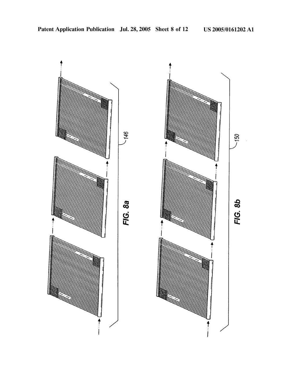
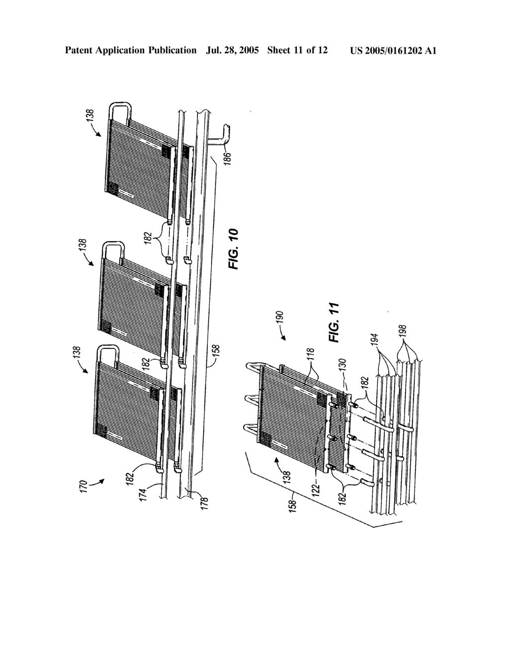
19 US 2005/ A1 Jul. 28, 2005 eration System. After determining how many Standard-sized microchannel condenser coils 14a, 14b or 64a, 64b will be required, the manufacturer may utilize their capabilities to put together the condenser assembly 10 or 62. Fluid con nections may be made by brazing or welding processes, or releasable couplings may be used to allow Serviceability of the coils 14a, 14b or 64a, 64b. Further, the fans 50 and the fan shrouds 54 may be manufactured or purchased by the condenser assembly manufacturer in Standard sizes to match up with the Standard-sized microchannel condenser coils 14a, 14b, 64a, 64b. Also, the frame 18 may be either custom made to Support multiple connected microchannel con denser coils 14a, 14b or 64a, 64b, or the frame 18 may be Standard-sized to Support a Single or dual microchannel condenser coils 14a, 14b or 64a, 64b, for example. This method of assembling the condenser assemblies 10, 62 may allow the manufacturer to Streamline their operation, which in turn may result in decreased costs for the manufacturer Although only two microchannel condenser coils 14a, 14b or 64a, 64b are shown in the illustrated construc tions of FIGS. 1 and 4, more or less than two microchannel condenser coils 14a, 14b or 64a, 64b may be included in the condenser assemblies 10 or 62 to satisfy the total heat load of the refrigeration System in which the microchannel con denser coils 14a, 14b or 64a, 64b will be used With reference to FIGS. 6a and 6b, other con denser coils may be utilized in the condenser assemblies 10, 62. FIG. 6a illustrates a microchannel condenser coil 98 substantially similar to the coils 14a, 14b, 64a, 64b with the exception that the coil 98 includes multiple inlet ports 102 and outlet ports 106. This style of microchannel condenser coil 98 may provide a better distribution of vaporized refrigerant to an inlet manifold 110 of the coil 98, in addition to a better distribution of liquid refrigerant from an outlet manifold 114 of the coil FIG. 6b illustrates another microchannel con denser coil 118 substantially similar to the coils 14a, 14b, 64a, 64b, 98 with the exception that the coil 118 is divided into two separate and distinct fluid circuits by a baffle 122 positioned in an inlet manifold 126 of the coil 118 and another baffle 130 positioned in an outlet manifold 134 of the coil 118. This style of microchannel condenser coil 118 may allow refrigerant from multiple refrigeration circuits (corresponding with multiple refrigeration display cases) to be passed through the coil 118. As a result, benefits such as a reduction in the number of Separate and dedicated con denser coils for each refrigeration circuit may be achieved by using the coil 118 of FIG. 6b. Subsequently, the amount of refrigerant that is carried in each refrigeration circuit may also be reduced With reference to FIGS. 7a-8b, any of the micro channel condenser coils 14a, 14b, 64a, 64b, 98, or 118 may be grouped together in either Single-row assemblies or multiple-row assemblies. FIGS. 7a and 7b illustrate coils being grouped in multiple-row assemblies 138, 142, respec tively. Specifically, FIGS. 7a and 7b illustrate coils being grouped in three-row assemblies 138, 142. In the three-row assemblies 138, 142 of FIGS. 7a and 7b, the coils are Stacked one on top of another Such that airflow is directed through all of the coils. Although three coils are shown in the multiple-row assemblies 138,142 of FIGS. 7a and 7b, more or less than three coils 14a, 14b, 64a, 64b, 98, or 118 may be used depending on the total heat load of a particular refrigeration system in which the assemblies 138, 142 are used. In addition, although FIGS. 7a and 7b generally illustrate the coils 14a, 14b, it should be known that any of the coils 14a, 14b, 64a, 64b, 98, or 118 may be used in forming the assemblies 138, With particular reference to FIG.7a, the three coils in the assembly 138 are shown in a fluid series connection, whereby refrigerant is passed through the three coils one after another. However, with particular reference to FIG.7b, the three coils in the assembly 142 are shown in a fluid parallel connection, whereby refrigerant is passed through the coils independently of one another. In constructing the condenser assemblies 10, 62, it is up to the manufacturer to determine if multiple-row assemblies 138,142 will be used. Furthermore, if multiple-row assemblies 138,142 are to be used, it is up to the manufacturer to determine whether to use an assembly 138 having coils grouped in a fluid Series connection, or an assembly 142 having coils grouped in a fluid parallel connection FIGS. 8a and 8b illustrate coils being grouped in single-row assemblies 146,150. Specifically, FIGS. 8a and 8b illustrate the coils being grouped in a single-row assem bly 146 of three coils. In the single-row assemblies 146,150 of FIGS. 8a and 8b, the coils are unfolded, or spread out Such that airflow passing through one of the coils is not directed through another of the three coils. Although three coils are shown in the single-row assemblies 146, 150 of FIGS. 8a and 8b, more or less than three coils may be used depending on the total heat load of the particular refrigera tion system in which the assemblies 146, 150 are used. In addition, although FIGS. 8a and 8b generally illustrate the coils 14a, 14b, it should be known that any of the coils 14a, 14b, 64a, 64b, 98, or 118 may be used in forming the assemblies 146, With particular reference to FIG.8a, the three coils in the assembly 146 are shown in a fluid Series connection, whereby refrigerant is passed through the three coils one after another. However, with particular reference to FIG. 8b, the three coils in the assembly 150 are shown in a fluid parallel connection, whereby refrigerant is passed through the coils independently of one another. In constructing the condenser assemblies 10, 62, it is up to the manufacturer to determine if single-row assemblies 146, 150 will be used. Furthermore, if single-row assemblies 146, 150 are to be used, it is up to the manufacturer to determine whether to use an assembly 146 having coils grouped in a fluid Series connection, or an assembly 150 having coils grouped in a fluid parallel connection With reference to FIGS. 9a-9b, one or more assem blies 138, 142, 146, or 150 may be grouped into a series configuration 154 or a parallel configuration 158 with an inlet header 162 and an outlet header 166. As shown in FIG. 9a, a three-row assembly 138 and a single row assembly 146 are grouped into a fluid Series configuration 154 between the inlet header 162 and the outlet header 166. Although the three-row assembly 138 and single-row assembly 146 are shown in the series configuration 154 of FIG. 9a, any combination of multiple-row assemblies 138 or 142 and single-row assemblies 146 or 150 may be used depending on the determination of the manufacturer. In addition, more or less than two assemblies 138,142,146, or 150 may be used

20 US 2005/ A1 Jul. 28, 2005 in the Series configuration 154 depending on the total heat load of the particular refrigeration System in which the Series configuration 154 is used. In addition, although FIG. 9a generally illustrates the coils 14a, 14b, it should be known that any of the coils 14a, 14b, 64a, 64b, 98, or 118 may be used in forming the assemblies 138, 142, 146, or 150 that comprise either the Series configuration 154 or the parallel configuration As shown in FIG. 9b, a three-row assembly 138 and a single row assembly 146 are grouped into a fluid parallel configuration 158 between the inlet header 162 and the outlet header 166. Although the three-row assembly 138 and the single-row assembly 146 are shown in the parallel configuration 158 of FIG. 9b, any combination of multiple row assemblies 138 or 142 and single-row assemblies 146 or 150 may be used depending on the determination of the manufacturer. In addition, more or less than two assemblies 138, 142, 146, or 150 may be used in the parallel configu ration 158 depending on the total heat load of the particular refrigeration system in which the parallel configuration 158 is used. In addition, although FIG. 9a generally illustrates the coils 14a, 14b, it should be known that any of the coils 14a, 14b, 64a, 64b, 98, or 118 may be used in forming the assemblies 138, 142, 146, or 150 that comprise either the series configuration 154 or the parallel configuration 158. Further, one or more baffles (not shown) may be positioned in the inlet and outlet headers 162, 166 between adjacent assemblies 138,142,146, or 150 to divide the configuration 154 or 158 into multiple fluid circuits Using the above terminology, FIG. 1 illustrates a single-row assembly 146 in a series configuration 154 between the inlet header 59 and the outlet header 61, whereby the coils 14a, 14b in the single-row assembly 146 are grouped into a fluid Series connection. Also, using the above terminology, FIG. 4 illustrates a single-row assembly 150 in a parallel configuration 158 between the inlet header 74 and the outlet header 86, whereby the coils 64a, 64b in the single-row assembly 150 are grouped into a fluid parallel connection FIG. 10 illustrates a third construction of a con denser assembly 170 including three two-row assemblies 138 in a parallel configuration 158 between an inlet header 174 and an outlet header 178. Each two-row assembly 138 includes two microchannel condenser coils 14a, 14b grouped in a fluid Series connection. Rather than being permanently connected to the inlet and outlet headers 174, 178, respectively, the coils 14a, 14b may be coupled to the inlet and outlet headers 174, 178 by fluid-tight releasable couplings 182. The couplings 182 are illustrated in FIG. 10, and may comprise any known Suitable fluid-tight, quick release coupling and/or releasable coupling. By using the couplings 182 in place of permanently connecting the coils 14a, 14b to the inlet and outlet headers 174, 178, the assemblies 138 are permitted to be removed and/or replaced to accommodate a varying heat load or to permit Service ability of a damaged assembly The condenser assembly 170 also includes an over sized outlet header 178 that also acts as a receiver for the liquid refrigerant discharged from the coils 14a, 14b. One or more liquid refrigerant outlets 186 may extend from the oversized outlet header 178 to distribute the liquid refriger ant to the one or more evaporators in the refrigeration System FIG. 11 illustrates a fourth construction of a con denser assembly 190 including a two-row assembly 138, with three Separate and distinct fluid circuits, in a parallel configuration 158 between multiple inlet headers 194 and multiple outlet headers 198. The two-row assembly 138 includes two microchannel condenser coils 118 grouped in a fluid Series connection. AS previously explained, the coils 118 each include respective baffles 122, 130 in the inlet and outlet manifolds 126, 134 to establish separate and distinct fluid circuits through the assembly 138. Like the assemblies 138 of FIG. 10, the assembly 138 of FIG. 11 may utilize fluid-tight couplings 182 to permit removal and/or replace ment of the assembly 138 to accommodate a varying heat load or to permit serviceability of a damaged assembly FIG. 12 illustrates a fifth construction of a con denser assembly 202 including a single-row assembly 150 between an inlet header 206 and an outlet header 210. The single-row assembly 150 includes four microchannel con denser coils 64a, 64b grouped in a fluid parallel connection. The coils 64a, 64b are inclined with respect to the inlet and outlet headers 206, 210, such that the footprint of the condenser assembly 202 is reduced (compared to the assem bly 62 of FIG. 4, for example). Although FIG. 12 generally illustrates the coils 64a, 64b, it should be known that any of the coils 14a, 14b, 64a, 64b, 98, or 118 may be used in forming the assembly As indicated by FIGS. 1, 4, and 10-12, the con denser assemblies 10, 62, 170, 190, 202 can be relatively Small or relatively large. If a relatively large heat load must be satisfied, a relatively large condenser assembly (Such as the assembly 170 of FIG. 10) having a plurality of assem blies 138, 142, 146, or 150 may be used. However, if a relatively Small heat load must be Satisfied, a relatively Small condenser assembly (such as the assemblies 10, 62 of FIGS. 1 and 4, respectively) having only one assembly 138, 142, 146, 150 may be used. The condenser assemblies 10, 62, 170, 190, 202 are shown for exemplary reasons only, and are not meant to limit the Spirit and/or Scope of the present invention. We claim: 1. A condenser assembly adapted to condense a refriger ant for use in a retail Store refrigeration System, the con denser assembly comprising: at least one microchannel condenser coil including an inlet manifold and an outlet manifold, the inlet mani fold having an inlet port for receiving the refrigerant, and the outlet manifold having an outlet port for discharging the refrigerant; and a frame Supporting the condenser coil. 2. The condenser assembly of claim 1, further comprising at least one fan Supported by the frame, the fan being configured to generate an airflow at least partially through the microchannel condenser coil. 3. The condenser assembly of claim 1, wherein the microchannel condenser coil includes a plurality of cooling fins Spaced thereon between 12 and 24 fins per inch. 4. The condenser assembly of claim 1, wherein the microchannel condenser coil includes a plurality of micro channels fluidly connecting the inlet manifold and the outlet manifold, the microchannels measuring between about 0.5 mm by about 0.5 mm and about 4 mm by about 4 mm in cross-section.

21 US 2005/ A1 Jul. 28, A condenser assembly adapted to condense a refriger ant for use in a retail Store refrigeration System, the con denser assembly comprising: a first microchannel condenser coil configured Such that the refrigerant makes at least one pass therethrough; a Second microchannel condenser coil fluidly connected with the first microchannel condenser coil, the Second microchannel condenser coil being configured Such that the refrigerant makes at least one pass through the Second microchannel condenser coil after making at least one pass through the first microchannel condenser coil; and a frame Supporting the first and Second microchannel condenser coils. 6. The condenser assembly of claim 5, further comprising at least one fan Supported by the frame, the fan being configured to generate an airflow at least partially through at least one of the first and Second microchannel condenser coils. 7. The condenser assembly of claim 5, wherein at least one of the first and Second microchannel condenser coils include a plurality of cooling fins Spaced thereon between 12 and 24 fins per inch. 8. The condenser assembly of claim 5, wherein at least one of the first and Second microchannel condenser coils include a plurality of microchannels fluidly connecting the inlet manifold and the outlet manifold, the microchannels measuring between about 0.5 mm by about 0.5 mm and about 4 mm by about 4 mm in cross-section. 9. The condenser assembly of claim 5, wherein the first and Second microchannel condenser coils each include an inlet manifold and an outlet manifold, and wherein the outlet manifold of the first microchannel condenser coil is fluidly connected with the inlet manifold of the Second microchan nel condenser coil. 10. The condenser assembly of claim 9, wherein the respective inlet manifolds each include at least one inlet port, and the respective outlet manifolds each include at least one outlet port, and wherein the outlet port of the first microchannel condenser coil is coupled to the inlet port of the Second microchannel condenser coil. 11. The condenser assembly of claim 5, wherein the Second microchannel condenser coil is in a fluid Series connection with the first microchannel condenser coil. 12. A condenser assembly adapted to condense a refrig erant for use in a retail Store refrigeration System, the condenser assembly comprising: a first microchannel condenser coil configured Such that the refrigerant makes at least one pass therethrough; a Second microchannel condenser coil configured Such that the refrigerant makes at least one pass there through; an inlet header fluidly connected with the first and second microchannel condenser coils, the inlet header being configured to deliver the refrigerant to the first and Second microchannel condenser coils, an outlet header fluidly connected with the first and Second microchannel condenser coils, the outlet header being configured to receive refrigerant from the first and Second microchannel condenser coils, wherein the first and Second microchannel condenser coils are con nected to receive and deliver refrigerant in a parallel relationship between the inlet and outlet headers, and a frame Supporting the first and Second microchannel condenser coils. 13. The condenser assembly of claim 12, further com prising at least one fan Supported by the frame, the fan being configured to generate an airflow at least partially through at least one of the first and Second microchannel condenser coils. 14. The condenser assembly of claim 12, wherein at least one of the first and Second microchannel condenser coils include a plurality of cooling fins Spaced thereon between 12 and 24 fins per inch. 15. The condenser assembly of claim 12, wherein the first and Second microchannel condenser coils each include an inlet manifold and an outlet manifold. 16. The condenser assembly of claim 15, wherein the inlet and outlet manifolds of the first and Second microchannel condenser coils are fluidly connected by a plurality of microchannels, the microchannels measuring between about 0.5 mm by about 0.5 mm and about 4 mm by about 4 mm in cross-section. 17. The condenser assembly of claim 15, wherein the inlet manifolds of the first and Second microchannel condenser coils are fluidly connected with the inlet header. 18. The condenser assembly of claim 17, wherein the inlet manifolds of the first and Second microchannel condenser coils each include at least one inlet port, the at least one inlet port of the first microchannel condenser coil being coupled to the inlet header, and the at least one inlet port of the Second microchannel condenser coil being coupled to the inlet header. 19. The condenser assembly of claim 15, wherein the outlet manifolds of the first and Second microchannel con denser coils are fluidly connected with the outlet header. 20. The condenser assembly of claim 19, wherein the outlet manifolds of the first and Second microchannel con denser coils each include at least one outlet port, the at least one outlet port of the first microchannel condenser coil being coupled to the outlet header, and the at least one outlet port of the Second microchannel condenser coil being coupled to the outlet header. 21. A method of assembling a condenser assembly adapted to condense a refrigerant for use in a retail Store refrigeration System, the method comprising: providing a first microchannel condenser coil configured Such that the refrigerant makes at least one pass there through; fluidly connecting the first microchannel condenser coil to a Second microchannel condenser coil configured Such that the refrigerant makes at least one pass through the Second microchannel condenser after making at least one pass through the first microchannel condenser coil; and Supporting the first and Second microchannel condenser coils with a frame. 22. The method of claim 21, further comprising position ing at least one fan over at least one of the first and Second microchannel condenser coils, the fan being configured to generate an airflow through the at least one of the first and Second microchannel condenser coils.

22 US 2005/ A1 Jul. 28, The method of claim 21, wherein fluidly connecting the first microchannel condenser coil to the Second micro channel condenser coil includes coupling an outlet port of the first microchannel condenser coil with an inlet port of the Second microchannel condenser coil. 24. The method of claim 21, further comprising: calculating a total heat load of the refrigeration System; and determining how many microchannel condenser coils should be fluidly interconnected. 25. A method of assembling a condenser assembly adapted to condense a refrigerant for use in a retail Store refrigeration System, the method comprising: providing a first microchannel condenser coil configured Such that the refrigerant makes at least one pass there through; providing a Second microchannel condenser coil config ured Such that the refrigerant makes at least one pass therethrough; fluidly connecting an inlet header to the first and Second microchannel condenser coils, the inlet header being configured to deliver the refrigerant to the first and Second microchannel condenser coils, fluidly connecting an outlet header to the first and Second microchannel condenser coils, the outlet header being configured to receive the refrigerant from the first and Second microchannel condenser coils, wherein the first and Second microchannel condenser coils are con nected to receive and deliver refrigerant in a parallel relationship between the inlet and outlet headers, and Supporting the first and Second microchannel condenser coils with a frame. 26. The method of claim 25, further comprising position ing at least one fan over at least one of the first and Second microchannel condenser coils, the fan being configured to generate an airflow through the at least one of the first and Second microchannel condenser coils. 27. The method of claim 25, wherein fluidly connecting the inlet header to the first and Second microchannel con denser coils includes coupling respective inlet ports of the first and Second microchannel condenser coils to the inlet header. 28. The method of claim 25, wherein fluidly connecting the outlet header to the first and Second microchannel condenser coils includes coupling respective outlet ports of the first and Second microchannel condenser coils to the outlet header. 29. The method of claim 25, further comprising: calculating a total heat load of the refrigeration System; and determining how many microchannel condenser coils should be fluidly interconnected.
(12) Patent Application Publication (10) Pub. No.: US 2004/ A1
 Patent Application Publication (10) Pub. No.: US 2004/ A1") (19) United States US 20040206110A1 (12) Patent Application Publication (10) Pub. No.: US 2004/0206110 A1 Lifson et al. (43) Pub. Date: (54) VAPOR COMPRESSION SYSTEM WITH BYPASS/ECONOMIZER CIRCUITS (76)
(19) United States US 20040206110A1 (12) Patent Application Publication (10) Pub. No.: US 2004/0206110 A1 Lifson et al. (43) Pub. Date: (54) VAPOR COMPRESSION SYSTEM WITH BYPASS/ECONOMIZER CIRCUITS (76)
(12) (10) Patent No.: US 9, B2. Schaeffer et al. (45) Date of Patent: Jun. 13, 2017
 (10) Patent No.: US 9, B2. Schaeffer et al. (45) Date of Patent: Jun. 13, 2017") United States Patent USOO9677796B2 (12) (10) Patent No.: US 9,677.796 B2 Schaeffer et al. (45) Date of Patent: Jun. 13, 2017 (54) MODULAR REFRIGERATIONASSEMBLY 2,585,360 A * 2/1952 Williams... F25D 3.06
United States Patent USOO9677796B2 (12) (10) Patent No.: US 9,677.796 B2 Schaeffer et al. (45) Date of Patent: Jun. 13, 2017 (54) MODULAR REFRIGERATIONASSEMBLY 2,585,360 A * 2/1952 Williams... F25D 3.06
A1(t1) (12) Patent Application Publication (10) Pub. No.: US 2011/ A1. (19) United States. Jiang et al. (43) Pub. Date: Sep.
 (12) Patent Application Publication (10) Pub. No.: US 2011/ A1. (19) United States. Jiang et al. (43) Pub. Date: Sep.") (19) United States US 2011 O232884A1 (12) Patent Application Publication (10) Pub. No.: US 2011/0232884 A1 Jiang et al. (43) Pub. Date: Sep. 29, 2011 (54) HEAT EXCHANGER (75) Inventors: Jianlong Jiang,
(19) United States US 2011 O232884A1 (12) Patent Application Publication (10) Pub. No.: US 2011/0232884 A1 Jiang et al. (43) Pub. Date: Sep. 29, 2011 (54) HEAT EXCHANGER (75) Inventors: Jianlong Jiang,
(12) United States Patent
 United States Patent") US008011 196B2 (12) United States Patent Eber et al. (54) REFRIGERANT CONTROL OF A HEATRECOVERY CHILLER (75) Inventors: Alan Hv Eber, La Crosse, WI (US); Steven J. Pitts, LaCrescent, MN (US); Brian T.
US008011 196B2 (12) United States Patent Eber et al. (54) REFRIGERANT CONTROL OF A HEATRECOVERY CHILLER (75) Inventors: Alan Hv Eber, La Crosse, WI (US); Steven J. Pitts, LaCrescent, MN (US); Brian T.
-50. Liquid outlet 1-1. Liquid outlet 2-1. Liquid outlet b. Liquid outlet 4-1. N-Liquid inlet 4. N-Liquid inlet 2.
 (19) United States (12) Patent Application Publication (10) Pub. No.: US 2008/0196442 A1 Lu US 2008O196442A1 (43) Pub. Date: Aug. 21, 2008 (54) (75) (73) (21) (22) (60) AIRCRAFT GALLEY REFRGERATION SYSTEM
(12) Patent Application Publication (10) Pub. No.: US 2014/ A1
 Patent Application Publication (10) Pub. No.: US 2014/ A1") (19) United States US 2014O137590A1 (12) Patent Application Publication (10) Pub. No.: US 2014/0137590 A1 Chopko et al. (43) Pub. Date: May 22, 2014 (54) INTEGRATED TRANSPORT Publication Classification
(19) United States US 2014O137590A1 (12) Patent Application Publication (10) Pub. No.: US 2014/0137590 A1 Chopko et al. (43) Pub. Date: May 22, 2014 (54) INTEGRATED TRANSPORT Publication Classification
(12) Patent Application Publication (10) Pub. No.: US 2004/ A1
 Patent Application Publication (10) Pub. No.: US 2004/ A1") (19) United States US 20040188059A1 (12) Patent Application Publication (10) Pub. No.: US 2004/0188059 A1 Todd, JR. et al. (43) Pub. Date: Sep. 30, 2004 (54) HEAT PIPE SYSTEM FOR COOLING FLYWHEEL ENERGY
(19) United States US 20040188059A1 (12) Patent Application Publication (10) Pub. No.: US 2004/0188059 A1 Todd, JR. et al. (43) Pub. Date: Sep. 30, 2004 (54) HEAT PIPE SYSTEM FOR COOLING FLYWHEEL ENERGY
(12) Patent Application Publication (10) Pub. No.: US 2012/ A1
 Patent Application Publication (10) Pub. No.: US 2012/ A1") (19) United States (12) Patent Application Publication (10) Pub. No.: US 2012/0017627 A1 Jeong et al. US 201200 17627A1 (43) Pub. Date: Jan. 26, 2012 (54) (75) (73) (21) (22) (86) (30) APPARATUS FOR PURIFYING
(19) United States (12) Patent Application Publication (10) Pub. No.: US 2012/0017627 A1 Jeong et al. US 201200 17627A1 (43) Pub. Date: Jan. 26, 2012 (54) (75) (73) (21) (22) (86) (30) APPARATUS FOR PURIFYING
(12) Patent Application Publication (10) Pub. No.: US 2005/ A1. Weng et al. (43) Pub. Date: Jun. 23, 2005
 Patent Application Publication (10) Pub. No.: US 2005/ A1. Weng et al. (43) Pub. Date: Jun. 23, 2005") (19) United States US 2005O133195A1 (12) Patent Application Publication (10) Pub. No.: US 2005/0133195A1 Weng et al. (43) Pub. Date: Jun. 23, 2005 (54) HEAT EXCHANGER USING WATER LIQUID (52) U.S. C.. 165/53
(19) United States US 2005O133195A1 (12) Patent Application Publication (10) Pub. No.: US 2005/0133195A1 Weng et al. (43) Pub. Date: Jun. 23, 2005 (54) HEAT EXCHANGER USING WATER LIQUID (52) U.S. C.. 165/53
(12) Patent Application Publication (10) Pub. No.: US 2004/ A1
 Patent Application Publication (10) Pub. No.: US 2004/ A1") (19) United States US 20040000399A1 (12) Patent Application Publication (10) Pub. No.: US 2004/0000399 A1 Gavula (43) Pub. Date: Jan. 1, 2004 (54) AIR-TO-AIR HEAT PUMP DEFROST BYPASS LOOP (76) Inventor:
(19) United States US 20040000399A1 (12) Patent Application Publication (10) Pub. No.: US 2004/0000399 A1 Gavula (43) Pub. Date: Jan. 1, 2004 (54) AIR-TO-AIR HEAT PUMP DEFROST BYPASS LOOP (76) Inventor:
(12) Patent Application Publication (10) Pub. No.: US 2013/ A1
 Patent Application Publication (10) Pub. No.: US 2013/ A1") (19) United States US 2013 0098582A1 (12) Patent Application Publication (10) Pub. No.: US 2013/0098582 A1 Stark (43) Pub. Date: Apr. 25, 2013 (54) METHOD USING HEAT PIPES WITH MULTIPLE EVAPORATOR/CONDENSER
(19) United States US 2013 0098582A1 (12) Patent Application Publication (10) Pub. No.: US 2013/0098582 A1 Stark (43) Pub. Date: Apr. 25, 2013 (54) METHOD USING HEAT PIPES WITH MULTIPLE EVAPORATOR/CONDENSER
(12) United States Patent
 United States Patent") USOO969604.4B2 (12) United States Patent Shafer et al. (10) Patent No.: (45) Date of Patent: Jul. 4, 2017 (54) AIR CONDITIONER UNITS AND METHODS FOR PROVIDING MAKE-UP AR (71) Applicant: General Electric
USOO969604.4B2 (12) United States Patent Shafer et al. (10) Patent No.: (45) Date of Patent: Jul. 4, 2017 (54) AIR CONDITIONER UNITS AND METHODS FOR PROVIDING MAKE-UP AR (71) Applicant: General Electric
(12) Patent Application Publication (10) Pub. No.: US 2009/ A1
 Patent Application Publication (10) Pub. No.: US 2009/ A1") (19) United States US 2009001 0625A1 (12) Patent Application Publication (10) Pub. No.: US 2009/0010625 A1 FOWler et al. (43) Pub. Date: Jan. 8, 2009 (54) FLOW THROUGH HEATER (75) Inventors: Lucas L. Fowler,
(19) United States US 2009001 0625A1 (12) Patent Application Publication (10) Pub. No.: US 2009/0010625 A1 FOWler et al. (43) Pub. Date: Jan. 8, 2009 (54) FLOW THROUGH HEATER (75) Inventors: Lucas L. Fowler,
(12) (10) Patent No.: US 7, B2 Army, Jr. et al. (45) Date of Patent: Mar. 13, 2007
 (10) Patent No.: US 7, B2 Army, Jr. et al. (45) Date of Patent: Mar. 13, 2007") United States Patent USOO7188488B2 (12) (10) Patent No.: Army, Jr. et al. (45) Date of Patent: Mar. 13, 2007 (54) PACK AND A HALF CONDENSING CYCLE 2003/0084681 A1* 5/2003 Haas... 62/402 PACK WITH COMBINED
United States Patent USOO7188488B2 (12) (10) Patent No.: Army, Jr. et al. (45) Date of Patent: Mar. 13, 2007 (54) PACK AND A HALF CONDENSING CYCLE 2003/0084681 A1* 5/2003 Haas... 62/402 PACK WITH COMBINED
into "ill (12) Patent Application Publication (10) Pub. No.: US 2008/ A1 (19) United States 12d Roberts (43) Pub. Date: Feb.
 Patent Application Publication (10) Pub. No.: US 2008/ A1 (19) United States 12d Roberts (43) Pub. Date: Feb.") (19) United States US 2008.0034781A1 (12) Patent Application Publication (10) Pub. No.: US 2008/0034781 A1 Roberts (43) Pub. Date: Feb. 14, 2008 (54) BEVERAGE PITCHER COLD PLATE STATION (76) Inventor:
(19) United States US 2008.0034781A1 (12) Patent Application Publication (10) Pub. No.: US 2008/0034781 A1 Roberts (43) Pub. Date: Feb. 14, 2008 (54) BEVERAGE PITCHER COLD PLATE STATION (76) Inventor:
(12) Patent Application Publication (10) Pub. No.: US 2005/ A1
 Patent Application Publication (10) Pub. No.: US 2005/ A1") (19) United States US 2005.0072175A1 (12) Patent Application Publication (10) Pub. No.: US 2005/0072175A1 Umeo et al. (43) Pub. Date: Apr. 7, 2005 (54) AIR CONDITIONER ANDTRUCK EQUIPPED WITH SAME (76)
(19) United States US 2005.0072175A1 (12) Patent Application Publication (10) Pub. No.: US 2005/0072175A1 Umeo et al. (43) Pub. Date: Apr. 7, 2005 (54) AIR CONDITIONER ANDTRUCK EQUIPPED WITH SAME (76)
SYS; Só-N III. sžess 43. United States Patent (19) Voorhis 5,706, Jan. 13, Date of Patent: Patent Number:
 Voorhis 5,706, Jan. 13, Date of Patent: Patent Number:") United States Patent (19) Voorhis III 11 45 US005706670A Patent Number: Date of Patent: Jan. 13, 1998 54 BDIRECTIONAL METERD FLOW CONTROL DEVICE (75) 73 21 22 51 52 58) 56 Inventor: Roger J. Voorhis, Pennellville,
United States Patent (19) Voorhis III 11 45 US005706670A Patent Number: Date of Patent: Jan. 13, 1998 54 BDIRECTIONAL METERD FLOW CONTROL DEVICE (75) 73 21 22 51 52 58) 56 Inventor: Roger J. Voorhis, Pennellville,
(12) Patent Application Publication (10) Pub. No.: US 2008/ A1
 Patent Application Publication (10) Pub. No.: US 2008/ A1") US 2008.0005926A1 (19) United States (12) Patent Application Publication (10) Pub. No.: US 2008/0005926 A1 Goggin (43) Pub. Date: Jan. 10, 2008 (54) APPARATUS AND METHOD FOR REDUCING CLOTHES DRYER LINT
US 2008.0005926A1 (19) United States (12) Patent Application Publication (10) Pub. No.: US 2008/0005926 A1 Goggin (43) Pub. Date: Jan. 10, 2008 (54) APPARATUS AND METHOD FOR REDUCING CLOTHES DRYER LINT
(12) United States Patent
 United States Patent") (12) United States Patent Kuroki et al. USOO6467288B2 (10) Patent No.: (45) Date of Patent: Oct. 22, 2002 (54) HEAT-PUMP WATER HEATER (75) Inventors: Jyouji Kuroki, Kariya (JP); Hisayoshi Sakakibara, Nishio
(12) United States Patent Kuroki et al. USOO6467288B2 (10) Patent No.: (45) Date of Patent: Oct. 22, 2002 (54) HEAT-PUMP WATER HEATER (75) Inventors: Jyouji Kuroki, Kariya (JP); Hisayoshi Sakakibara, Nishio
(12) United States Patent (10) Patent No.: US 7,654,310 B2. Li (45) Date of Patent: Feb. 2, 2010
 United States Patent (10) Patent No.: US 7,654,310 B2. Li (45) Date of Patent: Feb. 2, 2010") USOO765431 OB2 (12) United States Patent (10) Patent No.: Li (45) Date of Patent: Feb. 2, 2010 (54) LOOP HEAT PIPE 6,840,304 B1* 1/2005 Kobayashi et al.... 165,111 7,231,961 B2 * 6/2007 Alex et al....
USOO765431 OB2 (12) United States Patent (10) Patent No.: Li (45) Date of Patent: Feb. 2, 2010 (54) LOOP HEAT PIPE 6,840,304 B1* 1/2005 Kobayashi et al.... 165,111 7,231,961 B2 * 6/2007 Alex et al....
(12) Patent Application Publication (10) Pub. No.: US 2007/ A1
 Patent Application Publication (10) Pub. No.: US 2007/ A1") (19) United States US 200700.44517A1 (12) Patent Application Publication (10) Pub. No.: US 2007/0044517 A1 Yang et al. (43) Pub. Date: Mar. 1, 2007 (54) DETERGENT SUPPLYING APPARATUS OF CLOTHES WASHING
(19) United States US 200700.44517A1 (12) Patent Application Publication (10) Pub. No.: US 2007/0044517 A1 Yang et al. (43) Pub. Date: Mar. 1, 2007 (54) DETERGENT SUPPLYING APPARATUS OF CLOTHES WASHING
(12) United States Patent
 United States Patent") (12) United States Patent Vogel et al. USOO6286322B1 (10) Patent No.: (45) Date of Patent: US 6,286,322 B1 Sep. 11, 2001 (54) (75) (73) (*) (21) (22) (51) (52) (58) (56) HOT GAS DEFROST REFRIGERATION SYSTEM
(12) United States Patent Vogel et al. USOO6286322B1 (10) Patent No.: (45) Date of Patent: US 6,286,322 B1 Sep. 11, 2001 (54) (75) (73) (*) (21) (22) (51) (52) (58) (56) HOT GAS DEFROST REFRIGERATION SYSTEM
(12) Patent Application Publication (10) Pub. No.: US 2005/ A1
 Patent Application Publication (10) Pub. No.: US 2005/ A1") (19) United States (12) Patent Application Publication (10) Pub. No.: US 2005/0160759 A1 Chaney et al. US 2005O160759A1 (43) Pub. Date: (54) (75) (73) (21) (22) (60) CHILLER RESERVOR WITH INTERNAL BAFFLES
(19) United States (12) Patent Application Publication (10) Pub. No.: US 2005/0160759 A1 Chaney et al. US 2005O160759A1 (43) Pub. Date: (54) (75) (73) (21) (22) (60) CHILLER RESERVOR WITH INTERNAL BAFFLES
}} }} }} L'1 \( - Gas. ***`C Jààlà (O) EAGLACAK V2" () 212 ( /V/ (12) Patent Application Publication (10) Pub. No.: US 2014/ A1
 EAGLACAK V2 () 212 ( /V/ (12) Patent Application Publication (10) Pub. No.: US 2014/ A1") (19) United States US 20140224460A1 (12) Patent Application Publication (10) Pub. No.: US 2014/0224460 A1 Means (43) Pub. Date Aug. 14, 2014 (54) MICROCHANNEL HEAT EXCHANGER (71) Applicant: Trane International
(19) United States US 20140224460A1 (12) Patent Application Publication (10) Pub. No.: US 2014/0224460 A1 Means (43) Pub. Date Aug. 14, 2014 (54) MICROCHANNEL HEAT EXCHANGER (71) Applicant: Trane International
(12) Patent Application Publication (10) Pub. No.: US 2007/ A1. Day (43) Pub. Date: Oct. 11, 2007
 Patent Application Publication (10) Pub. No.: US 2007/ A1. Day (43) Pub. Date: Oct. 11, 2007") US 20070234909A1 (19) United States (12) Patent Application Publication (10) Pub. No.: US 2007/0234909 A1 Day (43) Pub. Date: Oct. 11, 2007 (54) DECORATOR TEMPERATURE CONTROL Publication Classification
US 20070234909A1 (19) United States (12) Patent Application Publication (10) Pub. No.: US 2007/0234909 A1 Day (43) Pub. Date: Oct. 11, 2007 (54) DECORATOR TEMPERATURE CONTROL Publication Classification
(12) Patent Application Publication (10) Pub. No.: US 2015/ A1
 Patent Application Publication (10) Pub. No.: US 2015/ A1") (19) United States US 2015O168032A1 (12) Patent Application Publication (10) Pub. No.: US 2015/0168032 A1 Steele (43) Pub. Date: Jun. 18, 2015 (54) POWER SUPPLY SYSTEM FORTRANSPORT Publication Classification
(19) United States US 2015O168032A1 (12) Patent Application Publication (10) Pub. No.: US 2015/0168032 A1 Steele (43) Pub. Date: Jun. 18, 2015 (54) POWER SUPPLY SYSTEM FORTRANSPORT Publication Classification
(12) Patent Application Publication (10) Pub. No.: US 2016/ A1
 Patent Application Publication (10) Pub. No.: US 2016/ A1") (19) United States US 201602O767OA1 (12) Patent Application Publication (10) Pub. No.: US 2016/0207670 A1 CHOU (43) Pub. Date: Jul. 21, 2016 (54) ONE-PIECE FOOD CONTAINER WITH RIM (52) U.S. Cl. CPC...
(19) United States US 201602O767OA1 (12) Patent Application Publication (10) Pub. No.: US 2016/0207670 A1 CHOU (43) Pub. Date: Jul. 21, 2016 (54) ONE-PIECE FOOD CONTAINER WITH RIM (52) U.S. Cl. CPC...
United States Patent 19
 United States Patent 19 USOO5853046A 11 Patent Number: 5,853,046 Williams et al. (45) Date of Patent: Dec. 29, 1998 54) HEAT EXCHANGER SEAL APPARATUS 4.914,929 4/1990 Shimazaki. 5,036,931 8/1991 Iritani.
(12) United States Patent (10) Patent No.: US 6,920,917 B2
 United States Patent (10) Patent No.: US 6,920,917 B2") USOO6920917B2 (12) United States Patent (10) Patent No.: Inoue et al. (45) Date of Patent: Jul. 26, 2005 (54) DOUBLE-PIPE HEAT EXCHANGER 5,950,716 A 9/1999 Appelquist et al.... 165/109.1 6,220,344 B1 *
USOO6920917B2 (12) United States Patent (10) Patent No.: Inoue et al. (45) Date of Patent: Jul. 26, 2005 (54) DOUBLE-PIPE HEAT EXCHANGER 5,950,716 A 9/1999 Appelquist et al.... 165/109.1 6,220,344 B1 *
United States Patent Modine et al.
 United States Patent Modine et al. 54 MODULAR AR COOLED CONDENSER 72) Inventors: Arthur B. Modine; Homer D. Hug gins; Neal A. Cook, all of Racine, Wis. 73) Assignee: Modine Manufacturing Company 22 Filed:
Dec. 15, ,318. Filed July 26, Sheets-Sheet l REFRIGERATING SYSTEM N. H. GAY
 Dec. 1, 1931. N. H. GAY 1836,318 REFRIGERATING SYSTEM Filed July 26, 1926 2 Sheets-Sheet l Dec. 1, 1931. N. H. GAY REFRIGERATING SYSTEM Filed July 26, l926 l,836,318 2 Sheets-Sheet 2 Patented Dec. 1, 1931
(12) Patent Application Publication (10) Pub. No.: US 2010/ A1
 Patent Application Publication (10) Pub. No.: US 2010/ A1") US 20100205768A1 (19) United States (12) Patent Application Publication (10) Pub. No.: US 2010/0205768 A1 Oh (43) Pub. Date: Aug. 19, 2010 (54) BRUSH ASSEMBLY OF VACUUM CLEANER (30) Foreign Application
US 20100205768A1 (19) United States (12) Patent Application Publication (10) Pub. No.: US 2010/0205768 A1 Oh (43) Pub. Date: Aug. 19, 2010 (54) BRUSH ASSEMBLY OF VACUUM CLEANER (30) Foreign Application
(2) Patent Application Publication (10) Pub. No.: US 2009/ A1
 Patent Application Publication (10) Pub. No.: US 2009/ A1") (19) United tates U 20090094991A1 (2) Patent Application Publication (10) Pub. No.: U 2009/0094991A1 Yu et al. (43) Pub. Date: Apr. 16, 2009 9 (54) HIGH EFFICIENCY HYBRID AIR Publication Classification
(19) United tates U 20090094991A1 (2) Patent Application Publication (10) Pub. No.: U 2009/0094991A1 Yu et al. (43) Pub. Date: Apr. 16, 2009 9 (54) HIGH EFFICIENCY HYBRID AIR Publication Classification
(12) United States Patent
 United States Patent") USOO9655489B2 (12) United States Patent Ha et al. (10) Patent No.: (45) Date of Patent: US 9,655.489 B2 May 23, 2017 (54) VACUUM CLEANER (71) Applicant: LG ELECTRONICS INC., Seoul (KR) (72) Inventors:
USOO9655489B2 (12) United States Patent Ha et al. (10) Patent No.: (45) Date of Patent: US 9,655.489 B2 May 23, 2017 (54) VACUUM CLEANER (71) Applicant: LG ELECTRONICS INC., Seoul (KR) (72) Inventors:
(12) Patent Application Publication (10) Pub. No.: US 2008/ A1
 Patent Application Publication (10) Pub. No.: US 2008/ A1") (19) United States US 20080047159A1 (12) Patent Application Publication (10) Pub. No.: US 2008/0047159 A1 Mackay (43) Pub. Date: Feb. 28, 2008 (54) SECONDARY LINT TRAP FOR Publication Classification RESIDENTAL
(19) United States US 20080047159A1 (12) Patent Application Publication (10) Pub. No.: US 2008/0047159 A1 Mackay (43) Pub. Date: Feb. 28, 2008 (54) SECONDARY LINT TRAP FOR Publication Classification RESIDENTAL
(12) Patent Application Publication (10) Pub. No.: US 2007/ A1
 Patent Application Publication (10) Pub. No.: US 2007/ A1") (19) United States US 20070074369A1 (12) Patent Application Publication (10) Pub. No.: US 2007/0074369 A1 Stuthers et al. (43) Pub. Date: Apr. 5, 2007 (54) DUAL PURPOSE FLOOR CLEANING APPARATUS AND METHOD
(19) United States US 20070074369A1 (12) Patent Application Publication (10) Pub. No.: US 2007/0074369 A1 Stuthers et al. (43) Pub. Date: Apr. 5, 2007 (54) DUAL PURPOSE FLOOR CLEANING APPARATUS AND METHOD
(12) United States Patent (10) Patent No.: US 6,176,097 B1. Kim (45) Date of Patent: Jan. 23, 2001
 United States Patent (10) Patent No.: US 6,176,097 B1. Kim (45) Date of Patent: Jan. 23, 2001") USOO6176097B1 (12) United States Patent (10) Patent No.: Kim (45) Date of Patent: Jan. 23, 2001 (54) SIDE BY SIDE TYPE REFRIGERATOR AND 5,477,699 12/1995 Guess et al.... 62/187 METHOD FOR CONTROLLING 5,732,561
USOO6176097B1 (12) United States Patent (10) Patent No.: Kim (45) Date of Patent: Jan. 23, 2001 (54) SIDE BY SIDE TYPE REFRIGERATOR AND 5,477,699 12/1995 Guess et al.... 62/187 METHOD FOR CONTROLLING 5,732,561
(12) Patent Application Publication (10) Pub. No.: US 2007/ A1
 Patent Application Publication (10) Pub. No.: US 2007/ A1") (19) United States US 20070209656A1 (12) Patent Application Publication (10) Pub. No.: US 2007/0209656A1 Lee (43) Pub. Date: Sep. 13, 2007 (54) VAPOR HEATING TYPE COOKING APPARATUS (76) Inventor: Won-Ki
(19) United States US 20070209656A1 (12) Patent Application Publication (10) Pub. No.: US 2007/0209656A1 Lee (43) Pub. Date: Sep. 13, 2007 (54) VAPOR HEATING TYPE COOKING APPARATUS (76) Inventor: Won-Ki
219,432,433,436,528,529, 99,483 is ABSTRACT 56) References Cited
 References Cited") USOO6075229A United States Patent (19) 11 Patent Number: 6,075,229 Vanselow (45) Date of Patent: Jun. 13, 2000 54). CUP WARMER HOLDER 4,442,343 4/1984 Genuit et al.... 219/433 4,463,664 8/1984 Peace......
USOO6075229A United States Patent (19) 11 Patent Number: 6,075,229 Vanselow (45) Date of Patent: Jun. 13, 2000 54). CUP WARMER HOLDER 4,442,343 4/1984 Genuit et al.... 219/433 4,463,664 8/1984 Peace......
USOO A United States Patent (19) 11 Patent Number: 5,921,315 Dinh (45) Date of Patent: *Jul. 13, 1999
 11 Patent Number: 5,921,315 Dinh (45) Date of Patent: *Jul. 13, 1999") USOO592.1315A United States Patent (19) 11 Patent Number: 5,921,315 Dinh (45) Date of Patent: *Jul. 13, 1999 54) THREE-DIMENSIONAL HEAT PIPE 2 330 965 6/1977 France. 2 407 445 5/1979 France. 75 Inventor:
USOO592.1315A United States Patent (19) 11 Patent Number: 5,921,315 Dinh (45) Date of Patent: *Jul. 13, 1999 54) THREE-DIMENSIONAL HEAT PIPE 2 330 965 6/1977 France. 2 407 445 5/1979 France. 75 Inventor:
(12) Patent Application Publication (10) Pub. No.: US 2004/ A1
 Patent Application Publication (10) Pub. No.: US 2004/ A1") (19) United States US 2004O140251A1 (12) Patent Application Publication (10) Pub. No.: US 2004/0140251A1 Hsiao (43) Pub. Date: Jul. 22, 2004 (54) ULTRAVIOLET CLEANING WATER DEVICE (76) Inventor: Chih-Ling
(19) United States US 2004O140251A1 (12) Patent Application Publication (10) Pub. No.: US 2004/0140251A1 Hsiao (43) Pub. Date: Jul. 22, 2004 (54) ULTRAVIOLET CLEANING WATER DEVICE (76) Inventor: Chih-Ling
USOO A United States Patent (19) 11 Patent Number: 6,164,247 Iwasaki et al. (45) Date of Patent: Dec. 26, 2000 LLP
 11 Patent Number: 6,164,247 Iwasaki et al. (45) Date of Patent: Dec. 26, 2000 LLP") USOO6164247A United States Patent (19) 11 Patent Number: Iwasaki et al. (45) Date of Patent: Dec. 26, 2000 54 INTERMEDIATE FLUID TYPE WAPORIZER, 4,417,951 11/1983 Stanisic et al.... 122/492 AND NATURAL
USOO6164247A United States Patent (19) 11 Patent Number: Iwasaki et al. (45) Date of Patent: Dec. 26, 2000 54 INTERMEDIATE FLUID TYPE WAPORIZER, 4,417,951 11/1983 Stanisic et al.... 122/492 AND NATURAL
4-26. United States Patent (19) Woollenweber et al. R XI N Patent Number: 6,102,672 (45) Date of Patent: Aug. 15, (75)
 Woollenweber et al. R XI N Patent Number: 6,102,672 (45) Date of Patent: Aug. 15, (75)") United States Patent (19) Woollenweber et al. 54 (75) MOTOR-DRIVEN CENTRIFUGAL AIR COMPRESSOR WITH INTERNAL COOLING ARFLOW Inventors: William E. Woollenweber, Carlsbad; Edward M. Halimi, Montecito, both
United States Patent (19) Woollenweber et al. 54 (75) MOTOR-DRIVEN CENTRIFUGAL AIR COMPRESSOR WITH INTERNAL COOLING ARFLOW Inventors: William E. Woollenweber, Carlsbad; Edward M. Halimi, Montecito, both
US A United States Patent (19) 11 Patent Number: 5,711,159. Whipple, III 45 Date of Patent: Jan. 27, 1998
 11 Patent Number: 5,711,159. Whipple, III 45 Date of Patent: Jan. 27, 1998") US00571 19A United States Patent (19) 11 Patent Number: 5,711,9 Whipple, III Date of Patent: Jan. 27, 1998 54 ENERGY-EFFICIENT REFRIGERATOR OTHER PUBLICATIONS CONTROL SYSTEM Donald E. Knoop et al., "An
US00571 19A United States Patent (19) 11 Patent Number: 5,711,9 Whipple, III Date of Patent: Jan. 27, 1998 54 ENERGY-EFFICIENT REFRIGERATOR OTHER PUBLICATIONS CONTROL SYSTEM Donald E. Knoop et al., "An
(12) Patent Application Publication (10) Pub. No.: US 2005/ A1
 Patent Application Publication (10) Pub. No.: US 2005/ A1") (19) United States US 2005OO39486A1 (12) Patent Application Publication (10) Pub. No.: US 2005/0039486A1 Knoll (43) Pub. Date: (54) SUBMERGED EVAPORATOR WITH (52) U.S. Cl.... 62/512; 62/515 INTEGRATED
(19) United States US 2005OO39486A1 (12) Patent Application Publication (10) Pub. No.: US 2005/0039486A1 Knoll (43) Pub. Date: (54) SUBMERGED EVAPORATOR WITH (52) U.S. Cl.... 62/512; 62/515 INTEGRATED
Tikhonov et al. (45) Date of Patent: Mar. 13, (54) REFRIGERATOR WITH SELECTIVE (56) References Cited ARFLOWPASSAGES BETWEEN THE
 Date of Patent: Mar. 13, (54) REFRIGERATOR WITH SELECTIVE (56) References Cited ARFLOWPASSAGES BETWEEN THE") (12) United States Patent USOO8132423B2 () Patent No.: US 8,132,423 B2 Tikhonov et al. (45) Date of Patent: Mar. 13, 2012 (54) REFRIGERATOR WITH SELECTIVE (56) References Cited ARFLOWPASSAGES BETWEEN THE
(12) United States Patent USOO8132423B2 () Patent No.: US 8,132,423 B2 Tikhonov et al. (45) Date of Patent: Mar. 13, 2012 (54) REFRIGERATOR WITH SELECTIVE (56) References Cited ARFLOWPASSAGES BETWEEN THE
(12) United States Patent (10) Patent No.: US 7,708,183 B2
 United States Patent (10) Patent No.: US 7,708,183 B2") USOO7708183B2 (12) United States Patent (10) Patent No.: Dautenhahn (45) Date of Patent: May 4, 2010 (54) REFLOW SOLDER OVEN WITH COOLING 5,611,476 A 3, 1997 Soderlund et al. DIFFUSER 5,641,341 A * 6/1997
USOO7708183B2 (12) United States Patent (10) Patent No.: Dautenhahn (45) Date of Patent: May 4, 2010 (54) REFLOW SOLDER OVEN WITH COOLING 5,611,476 A 3, 1997 Soderlund et al. DIFFUSER 5,641,341 A * 6/1997
Ahmed et al. (43) Pub. Date: Apr. 3, (54) FIELD WELDABLE CONNECTIONS (21) Appl. No.: 09/970,353
 Pub. Date: Apr. 3, (54) FIELD WELDABLE CONNECTIONS (21) Appl. No.: 09/970,353") US 2003.0062157A1 (19) United States (12) Patent Application Publication (10) Pub. No.: US 2003/0062157 A1 Ahmed et al. (43) Pub. Date: Apr. 3, 2003 (54) FIELD WELDABLE CONNECTIONS (21) Appl. No.: 09/970,353
US 2003.0062157A1 (19) United States (12) Patent Application Publication (10) Pub. No.: US 2003/0062157 A1 Ahmed et al. (43) Pub. Date: Apr. 3, 2003 (54) FIELD WELDABLE CONNECTIONS (21) Appl. No.: 09/970,353
(12) United States Patent
 United States Patent") (12) United States Patent Oikawa et al. USOO6778394B2 (10) Patent No.: (45) Date of Patent: Aug. 17, 2004 (54) ELECTRONIC DEVICE HAVING A HEAT DSSPATION MEMBER (75) Inventors: Hironori Oikawa, Hadano (JP);
(12) United States Patent Oikawa et al. USOO6778394B2 (10) Patent No.: (45) Date of Patent: Aug. 17, 2004 (54) ELECTRONIC DEVICE HAVING A HEAT DSSPATION MEMBER (75) Inventors: Hironori Oikawa, Hadano (JP);
(12) Patent Application Publication (10) Pub. No.: US 2006/ A1
 Patent Application Publication (10) Pub. No.: US 2006/ A1") (19) United States US 20060026976A1 (12) Patent Application Publication (10) Pub. No.: US 2006/0026976A1 Carpenter (43) Pub. Date: Feb. 9, 2006 (54) CLIMATE CONTROLAND DEHUMIDIFICATION SYSTEMAND METHOD
(19) United States US 20060026976A1 (12) Patent Application Publication (10) Pub. No.: US 2006/0026976A1 Carpenter (43) Pub. Date: Feb. 9, 2006 (54) CLIMATE CONTROLAND DEHUMIDIFICATION SYSTEMAND METHOD
(12) United States Patent (10) Patent No.: US 8,375,741 B2
 United States Patent (10) Patent No.: US 8,375,741 B2") US008375741B2 (12) United States Patent () Patent No.: Taras et al. () Date of Patent: Feb. 19, 2013 (54) REFRIGERANTSYSTEM WITH (56) References Cited INTERCOOLER AND LIQUID/VAPOR NJECTION U.S. PATENT
US008375741B2 (12) United States Patent () Patent No.: Taras et al. () Date of Patent: Feb. 19, 2013 (54) REFRIGERANTSYSTEM WITH (56) References Cited INTERCOOLER AND LIQUID/VAPOR NJECTION U.S. PATENT
(12) Patent Application Publication (10) Pub. No.: US 2006/ A1
 Patent Application Publication (10) Pub. No.: US 2006/ A1") (19) United States US 20060266O74A1 (12) Patent Application Publication (10) Pub. No.: US 2006/0266074 A1 Groll et al. (43) Pub. Date: (54) HEAT PUMP SYSTEM WITH MULTI-STAGE COMPRESSION (75) Inventors:
(19) United States US 20060266O74A1 (12) Patent Application Publication (10) Pub. No.: US 2006/0266074 A1 Groll et al. (43) Pub. Date: (54) HEAT PUMP SYSTEM WITH MULTI-STAGE COMPRESSION (75) Inventors:
(12) Patent Application Publication (10) Pub. No.: US 2002/ A1
 Patent Application Publication (10) Pub. No.: US 2002/ A1") (19) United States US 2002O14634.4A1 (12) Patent Application Publication (10) Pub. No.: US 2002/0146344 A1 WALTA (43) Pub. Date: Oct. 10, 2002 (54) SYSTEM FOR CLEANING, DISINFECTING AND/OR DRYING ENDOSCOPES
(19) United States US 2002O14634.4A1 (12) Patent Application Publication (10) Pub. No.: US 2002/0146344 A1 WALTA (43) Pub. Date: Oct. 10, 2002 (54) SYSTEM FOR CLEANING, DISINFECTING AND/OR DRYING ENDOSCOPES
IIIHHHHHHHHHHHHH. United States Patent (19) CSi. 11 Patent Number: 5,318,230 (45) Date of Patent: Jun. 7, Ferguson et al.
 CSi. 11 Patent Number: 5,318,230 (45) Date of Patent: Jun. 7, Ferguson et al.") United States Patent (19) Ferguson et al. 54 GARBAGE DISPOSAL ASSEMBLY WITH DECORATIVE SINK FLANGE MASK 75 Inventors: Lloyd G. Ferguson, Marietta, Ga.; Peter J. Taylor, Bishops Wood, United Kingdom 73)
United States Patent (19) Ferguson et al. 54 GARBAGE DISPOSAL ASSEMBLY WITH DECORATIVE SINK FLANGE MASK 75 Inventors: Lloyd G. Ferguson, Marietta, Ga.; Peter J. Taylor, Bishops Wood, United Kingdom 73)
(12) United States Patent
 United States Patent") US007997.965B2 (12) United States Patent Veuillet et al. () Patent No.: (45) Date of Patent: US 7.997.965 B2 Aug. 16, 2011 (54) AIR CONDITIONING SYSTEM (75) Inventors: Franck Veuillet, Nievroz (FR); Eric
US007997.965B2 (12) United States Patent Veuillet et al. () Patent No.: (45) Date of Patent: US 7.997.965 B2 Aug. 16, 2011 (54) AIR CONDITIONING SYSTEM (75) Inventors: Franck Veuillet, Nievroz (FR); Eric
(12) Patent Application Publication (10) Pub. No.: US 2008/ A1
 Patent Application Publication (10) Pub. No.: US 2008/ A1") (19) United States (12) Patent Application Publication (10) Pub. No.: US 2008/0173797 A1 Sanford et al. US 20080173797A1 (43) Pub. Date: Jul. 24, 2008 (54) (75) (73) (21) (22) PHOTOELECTRIC SWITCH Inventors:
(19) United States (12) Patent Application Publication (10) Pub. No.: US 2008/0173797 A1 Sanford et al. US 20080173797A1 (43) Pub. Date: Jul. 24, 2008 (54) (75) (73) (21) (22) PHOTOELECTRIC SWITCH Inventors:
United States Patent (19) Jackson
 Jackson") United States Patent (19) Jackson (54) 76 21 22) (51) 52) 58) 56) BUILDING EXTERIOR FIRE PREVENTION SYSTEM Inventor: Willie C. Jackson, 2.4808 Mission Blvd., Hayward, Calif. 94545 Appl. No.:754,792 Filed:
United States Patent (19) Jackson (54) 76 21 22) (51) 52) 58) 56) BUILDING EXTERIOR FIRE PREVENTION SYSTEM Inventor: Willie C. Jackson, 2.4808 Mission Blvd., Hayward, Calif. 94545 Appl. No.:754,792 Filed:
(12) Patent Application Publication (10) Pub. No.: US 2003/ A1
 Patent Application Publication (10) Pub. No.: US 2003/ A1") (19) United States US 2003O194330A1 (12) Patent Application Publication (10) Pub. o.: US 2003/0194330 A1 Lifson (43) Pub. Date: Oct. 16, 2003 (54) SHORT REVERSE ROTATIO OF COMPRESSOR AT STARTUP (76) Inventor:
(19) United States US 2003O194330A1 (12) Patent Application Publication (10) Pub. o.: US 2003/0194330 A1 Lifson (43) Pub. Date: Oct. 16, 2003 (54) SHORT REVERSE ROTATIO OF COMPRESSOR AT STARTUP (76) Inventor:
United States Patent (19) Koskela
 Koskela") United States Patent (19) Koskela 54 (76) (21) 22) 51 52) (58) 56 SOLAR WATER HEATING SYSTEMAND HEAT EXCHANGER FOR USE WITH EXISTING HOT WATER SYSTEMS Inventor: Marvin O. Koskela, 4222 E. Calle Redonda,
United States Patent (19) Koskela 54 (76) (21) 22) 51 52) (58) 56 SOLAR WATER HEATING SYSTEMAND HEAT EXCHANGER FOR USE WITH EXISTING HOT WATER SYSTEMS Inventor: Marvin O. Koskela, 4222 E. Calle Redonda,
USOO A United States Patent (19) 11 Patent Number: 5,875,645 Dunnigan (45) Date of Patent: Mar. 2, 1999
 11 Patent Number: 5,875,645 Dunnigan (45) Date of Patent: Mar. 2, 1999") USOO5875645A United States Patent (19) 11 Patent Number: Dunnigan (45) Date of Patent: Mar. 2, 1999 54). SELF-SEALING VENDING MACHINE 5,678,421 10/1997 Maynard et al.... 62/407 REFRIGERATION APPARATUS
USOO5875645A United States Patent (19) 11 Patent Number: Dunnigan (45) Date of Patent: Mar. 2, 1999 54). SELF-SEALING VENDING MACHINE 5,678,421 10/1997 Maynard et al.... 62/407 REFRIGERATION APPARATUS
United States Patent (19) Dean
 Dean") United States Patent (19) Dean 54 (76) 21) 22 63 51 52 58) 56) ARVENTTLATION CONTROL SYSTEM Inventor: Arthur C. Dean, 13403 Vimy Ridge Rd., Alexander, Ark. 72002 Appl. No.: 63,429 Filed: Jun. 18, 1987
United States Patent (19) Dean 54 (76) 21) 22 63 51 52 58) 56) ARVENTTLATION CONTROL SYSTEM Inventor: Arthur C. Dean, 13403 Vimy Ridge Rd., Alexander, Ark. 72002 Appl. No.: 63,429 Filed: Jun. 18, 1987
(12) Patent Application Publication (10) Pub. No.: US 2014/ A1
 Patent Application Publication (10) Pub. No.: US 2014/ A1") (19) United States US 20140374060A1 (12) Patent Application Publication (10) Pub. No.: US 2014/0374060 A1 Labaste Mauhe et al. (43) Pub. Date: (54) DEVICE FOR AIR CONDITIONING A DRIVE (52) U.S. Cl. TRAN
(19) United States US 20140374060A1 (12) Patent Application Publication (10) Pub. No.: US 2014/0374060 A1 Labaste Mauhe et al. (43) Pub. Date: (54) DEVICE FOR AIR CONDITIONING A DRIVE (52) U.S. Cl. TRAN
(12) Patent Application Publication (10) Pub. No.: US 2006/ A1
 Patent Application Publication (10) Pub. No.: US 2006/ A1") (19) United States US 20060277782A1 (12) Patent Application Publication (10) Pub. No.: Chen et al. (43) Pub. Date: Dec. 14, 2006 (54) NEGATIVE PRESSURE TYPE DRYING MACHINE THAT UTILIZES THE ENERGY OF THE
(19) United States US 20060277782A1 (12) Patent Application Publication (10) Pub. No.: Chen et al. (43) Pub. Date: Dec. 14, 2006 (54) NEGATIVE PRESSURE TYPE DRYING MACHINE THAT UTILIZES THE ENERGY OF THE
(12) Patent Application Publication (10) Pub. No.: US 2013/ A1
 Patent Application Publication (10) Pub. No.: US 2013/ A1") US 20130193219A1 (19) United States (12) Patent Application Publication (10) Pub. No.: US 2013/0193219 A1 Xia et al. (43) Pub. Date: Aug. 1, 2013 (54) LOW PRESSURE AND HIGH-LOW (52) U.S. Cl. TEMPERATURE
US 20130193219A1 (19) United States (12) Patent Application Publication (10) Pub. No.: US 2013/0193219 A1 Xia et al. (43) Pub. Date: Aug. 1, 2013 (54) LOW PRESSURE AND HIGH-LOW (52) U.S. Cl. TEMPERATURE
(12) United States Patent (10) Patent No.: US 6,361,301 B1
 United States Patent (10) Patent No.: US 6,361,301 B1") USOO636.1301B1 (12) United States Patent (10) Patent No.: Scaglotti et al. (45) Date of Patent: Mar. 26, 2002 (54) HEATER ASSEMBLY FOR BLOW MOLDING 5,256,341. 10/1993 Denis et al. PLASTIC PREFORMS 5,549,468
USOO636.1301B1 (12) United States Patent (10) Patent No.: Scaglotti et al. (45) Date of Patent: Mar. 26, 2002 (54) HEATER ASSEMBLY FOR BLOW MOLDING 5,256,341. 10/1993 Denis et al. PLASTIC PREFORMS 5,549,468
United States Patent (19) 11 Patent Number: 5,020,331
 11 Patent Number: 5,020,331") United States Patent (19) 11 Patent Number: Michny ) Date of Patent: Jun. 4, 1991 54 REFRIGERANT RECLAMATION SYSTEM 4,934,390 6/1990 SE v v 0 w al..." 62/77 4,938,031 7/1990 nz et al.... 62/149 (75) Inventor:
United States Patent (19) 11 Patent Number: Michny ) Date of Patent: Jun. 4, 1991 54 REFRIGERANT RECLAMATION SYSTEM 4,934,390 6/1990 SE v v 0 w al..." 62/77 4,938,031 7/1990 nz et al.... 62/149 (75) Inventor:
16 2 A. Z. % 17. (12) Patent Application Publication (10) Pub. No.: US 2010/ A1. (19) United States NZ S. S. ZN Z SS 33 N N NNNNNNNNNNNNXN
 Patent Application Publication (10) Pub. No.: US 2010/ A1. (19) United States NZ S. S. ZN Z SS 33 N N NNNNNNNNNNNNXN") (19) United States US 201001 86434A1 (12) Patent Application Publication (10) Pub. No.: US 2010/0186434 A1 LOu et al. (43) Pub. Date: (54) AUTOMOTIVE THERMOSTATIC EXPANSION VALVE WITH REDUCED HISS (75)
(19) United States US 201001 86434A1 (12) Patent Application Publication (10) Pub. No.: US 2010/0186434 A1 LOu et al. (43) Pub. Date: (54) AUTOMOTIVE THERMOSTATIC EXPANSION VALVE WITH REDUCED HISS (75)
(12) Patent Application Publication (10) Pub. No.: US 2015/ A1
 Patent Application Publication (10) Pub. No.: US 2015/ A1") (19) United States US 20150291450A1 (12) Patent Application Publication (10) Pub. No.: US 2015/0291450 A1 Sherzer (43) Pub. Date: Oct. 15, 2015 (54) METHOD FOR SOLIDS REMOVAL IN HEAT Publication Classification
(19) United States US 20150291450A1 (12) Patent Application Publication (10) Pub. No.: US 2015/0291450 A1 Sherzer (43) Pub. Date: Oct. 15, 2015 (54) METHOD FOR SOLIDS REMOVAL IN HEAT Publication Classification
(12) United States Patent (10) Patent No.: US 6,647,932 B1
 United States Patent (10) Patent No.: US 6,647,932 B1") USOO664.7932B1 (12) United States Patent (10) Patent No.: Cui et al. (45) Date of Patent: Nov. 18, 2003 (54) COMPACT BOILER WITH TANKLESS (56) References Cited HEATER FOR PROVIDING HEAT AND DOMESTIC HOT
USOO664.7932B1 (12) United States Patent (10) Patent No.: Cui et al. (45) Date of Patent: Nov. 18, 2003 (54) COMPACT BOILER WITH TANKLESS (56) References Cited HEATER FOR PROVIDING HEAT AND DOMESTIC HOT
United States Patent (19) Henle
 Henle") United States Patent (19) Henle 54 COMBINATION WATER SUPPLY AND WASTE HOLDING TANK (76) Inventor: George A. Henle, 920 Penfield St., Beecher, Ill. 60401 22 Filed: Jan. 15, 1975 (21) Appl. No.: 541,225
United States Patent (19) Henle 54 COMBINATION WATER SUPPLY AND WASTE HOLDING TANK (76) Inventor: George A. Henle, 920 Penfield St., Beecher, Ill. 60401 22 Filed: Jan. 15, 1975 (21) Appl. No.: 541,225
(12) Patent Application Publication (10) Pub. No.: US 2010/ A1
 Patent Application Publication (10) Pub. No.: US 2010/ A1") (19) United States US 2010O136392A1 (12) Patent Application Publication (10) Pub. No.: US 2010/0136392 A1 PULLIAM et al. (43) Pub. Date: Jun. 3, 2010 (54) CELL TEMPERATURE SENSING (21) Appl. No.: 12/571,926
(19) United States US 2010O136392A1 (12) Patent Application Publication (10) Pub. No.: US 2010/0136392 A1 PULLIAM et al. (43) Pub. Date: Jun. 3, 2010 (54) CELL TEMPERATURE SENSING (21) Appl. No.: 12/571,926
United States Patent (19)
") United States Patent (19) Studinger (54) MOBILE SELF CONTAINED PRESSURE SPRAYER 76 Inventor: John H. Studinger, 5700 Montview Blvd., Denver, Colo. 80207 (22 Filed: June 26, 1972 21 Appl. No. 266,415 52
United States Patent (19) Studinger (54) MOBILE SELF CONTAINED PRESSURE SPRAYER 76 Inventor: John H. Studinger, 5700 Montview Blvd., Denver, Colo. 80207 (22 Filed: June 26, 1972 21 Appl. No. 266,415 52
United States Patent (19) 11 Patent Number: 5,651,270 Low et al. 45 Date of Patent: Jul. 29, 1997
 11 Patent Number: 5,651,270 Low et al. 45 Date of Patent: Jul. 29, 1997") US005651270A United States Patent (19) 11 Patent Number: Low et al. 45 Date of Patent: Jul. 29, 1997 54 CORE-IN-SHELL HEAT EXCHANGERS FOR Attorney, Agent, or Firm--George E. Bogatie MULTISTAGE COMPRESSORS
US005651270A United States Patent (19) 11 Patent Number: Low et al. 45 Date of Patent: Jul. 29, 1997 54 CORE-IN-SHELL HEAT EXCHANGERS FOR Attorney, Agent, or Firm--George E. Bogatie MULTISTAGE COMPRESSORS
USOO A United States Patent (19) 11 Patent Number: 5,993,656 Cordani (45) Date of Patent: Nov.30, 1999
 11 Patent Number: 5,993,656 Cordani (45) Date of Patent: Nov.30, 1999") USOO5993656A United States Patent (19) 11 Patent Number: 5,993,656 Cordani (45) Date of Patent: Nov.30, 1999 54). SELECTIVE FLUIDABSORBING DEVICE 4,861,469 8/1989 Rossi et al.... 21.0/502.1 5,130,018 7/1992
USOO5993656A United States Patent (19) 11 Patent Number: 5,993,656 Cordani (45) Date of Patent: Nov.30, 1999 54). SELECTIVE FLUIDABSORBING DEVICE 4,861,469 8/1989 Rossi et al.... 21.0/502.1 5,130,018 7/1992
(12) Patent Application Publication (10) Pub. No.: US 2011/ A1
 Patent Application Publication (10) Pub. No.: US 2011/ A1") (19) United States (12) Patent Application Publication (10) Pub. No.: US 2011/0107760 A1 Quinn et al. US 2011 01 07760A1 (43) Pub. Date: May 12, 2011 (54) (75) (73) (21) (22) INTERCOOLER HAVING CONDENSATE
(19) United States (12) Patent Application Publication (10) Pub. No.: US 2011/0107760 A1 Quinn et al. US 2011 01 07760A1 (43) Pub. Date: May 12, 2011 (54) (75) (73) (21) (22) INTERCOOLER HAVING CONDENSATE
(12) United States Patent (10) Patent No.: US 6,639,797 B2
 United States Patent (10) Patent No.: US 6,639,797 B2") USOO66397.97B2 (12) United States Patent (10) Patent No.: Saeki et al. (45) Date of Patent: Oct. 28, 2003 (54) COMPUTER HAVING COOLING DEVICE 6,118,655 A 9/2000 Mecredy et al.... 361/687 6,315,033 B1 *
USOO66397.97B2 (12) United States Patent (10) Patent No.: Saeki et al. (45) Date of Patent: Oct. 28, 2003 (54) COMPUTER HAVING COOLING DEVICE 6,118,655 A 9/2000 Mecredy et al.... 361/687 6,315,033 B1 *
(12) Patent Application Publication (10) Pub. No.: US 2013/ A1
 Patent Application Publication (10) Pub. No.: US 2013/ A1") (19) United States (12) Patent Application Publication (10) Pub. No.: US 2013/0307237 A1 CHEN US 2013 0307237A1 (43) Pub. Date: Nov. 21, 2013 (54) MEDICAL CART SYSTEM (75) Inventor: (73) Assignee: (21)
(19) United States (12) Patent Application Publication (10) Pub. No.: US 2013/0307237 A1 CHEN US 2013 0307237A1 (43) Pub. Date: Nov. 21, 2013 (54) MEDICAL CART SYSTEM (75) Inventor: (73) Assignee: (21)
(12) United States Patent
 United States Patent") US009377236B2 (12) United States Patent Hinde et al. () Patent No.: US 9,377,236 B2 (45) Date of Patent: Jun. 28, 2016 (54) (71) (72) (73) (*) (21) (22) (86) (87) (65) (60) (51) (52) (58) CO2 REFRGERATION
US009377236B2 (12) United States Patent Hinde et al. () Patent No.: US 9,377,236 B2 (45) Date of Patent: Jun. 28, 2016 (54) (71) (72) (73) (*) (21) (22) (86) (87) (65) (60) (51) (52) (58) CO2 REFRGERATION
(12) Patent Application Publication (10) Pub. No.: US 2013/ A1
 Patent Application Publication (10) Pub. No.: US 2013/ A1") (19) United States US 20130298579A1 (12) Patent Application Publication (10) Pub. No.: US 2013/0298579 A1 Dingle et al. (43) Pub. Date: (54) VAPOR COMPRESSION DEHUMIDIFIER (52) U.S. Cl. USPC... 62/90;
(19) United States US 20130298579A1 (12) Patent Application Publication (10) Pub. No.: US 2013/0298579 A1 Dingle et al. (43) Pub. Date: (54) VAPOR COMPRESSION DEHUMIDIFIER (52) U.S. Cl. USPC... 62/90;
(12) Patent Application Publication (10) Pub. No.: US 2007/ A1
 Patent Application Publication (10) Pub. No.: US 2007/ A1") (19) United States (12) Patent Application Publication (10) Pub. No.: US 2007/0089676 A1 Klemm US 2007.0089676A1 (43) Pub. Date: Apr. 26, 2007 (54) ARRANGEMENT FOR THE VAPOR DEPOSITION ON SUBSTRATES (76)
(19) United States (12) Patent Application Publication (10) Pub. No.: US 2007/0089676 A1 Klemm US 2007.0089676A1 (43) Pub. Date: Apr. 26, 2007 (54) ARRANGEMENT FOR THE VAPOR DEPOSITION ON SUBSTRATES (76)
(12) United States Patent
 United States Patent") () United States Patent Wells et al. USOO6345685B1 (10) Patent No.: (45) Date of Patent: Feb., 2002 (54) LOUDSPEAKER SYSTEM (76) Inventors: Leigh D. Wells; Emma-Jane Smith, both of Providence Cottage,
() United States Patent Wells et al. USOO6345685B1 (10) Patent No.: (45) Date of Patent: Feb., 2002 (54) LOUDSPEAKER SYSTEM (76) Inventors: Leigh D. Wells; Emma-Jane Smith, both of Providence Cottage,
United States Patent (19) Bratt
 Bratt") United States Patent (19) Bratt 54) (75) (73) 21 22 63) (51) (52) (58) (56) HOT GAS ENGINE HEATER HEAD Inventor: Jan C. Bratt, Malmö, Sweden Assignee: United Stirling AB, Malmö, Sweden Appl. No.: 852,071
United States Patent (19) Bratt 54) (75) (73) 21 22 63) (51) (52) (58) (56) HOT GAS ENGINE HEATER HEAD Inventor: Jan C. Bratt, Malmö, Sweden Assignee: United Stirling AB, Malmö, Sweden Appl. No.: 852,071
(12) United States Patent (10) Patent No.: US 7.437,888 B2. Son et al. (45) Date of Patent: Oct. 21, 2008
 United States Patent (10) Patent No.: US 7.437,888 B2. Son et al. (45) Date of Patent: Oct. 21, 2008") US007437888B2 (12) United States Patent (10) Patent No.: US 7.437,888 B2 Son et al. (45) Date of Patent: Oct. 21, 2008 (54) REFRGERATOR 6,352,105 B1* 3/2002 Serratto... 165,221 6,488,009 B2 * 12/2002 Sakurai
US007437888B2 (12) United States Patent (10) Patent No.: US 7.437,888 B2 Son et al. (45) Date of Patent: Oct. 21, 2008 (54) REFRGERATOR 6,352,105 B1* 3/2002 Serratto... 165,221 6,488,009 B2 * 12/2002 Sakurai
(12) Patent Application Publication (10) Pub. No.: US 2010/ A1
 Patent Application Publication (10) Pub. No.: US 2010/ A1") (19) United States US 20100051713A1 (12) Patent Application Publication (10) Pub. No.: US 2010/0051713 A1 Back et al. (43) Pub. Date: (54) HOT WATER CIRCULATION SYSTEM (30) Foreign Application Priority
(19) United States US 20100051713A1 (12) Patent Application Publication (10) Pub. No.: US 2010/0051713 A1 Back et al. (43) Pub. Date: (54) HOT WATER CIRCULATION SYSTEM (30) Foreign Application Priority
(12) United States Patent
 United States Patent") USOO823 O714B2 (12) United States Patent Intagliata et al. (10) Patent No.: US 8,230,714 B2 (45) Date of Patent: Jul. 31, 2012 (54) (75) (73) (*) (21) (22) (65) (60) (51) (52) (58) DE CARRIER ASSEMBLY
USOO823 O714B2 (12) United States Patent Intagliata et al. (10) Patent No.: US 8,230,714 B2 (45) Date of Patent: Jul. 31, 2012 (54) (75) (73) (*) (21) (22) (65) (60) (51) (52) (58) DE CARRIER ASSEMBLY
(12) Patent Application Publication (10) Pub. No.: US 2014/ A1
 Patent Application Publication (10) Pub. No.: US 2014/ A1") (19) United States US 2014O130538A1 (12) Patent Application Publication (10) Pub. No.: US 2014/0130538 A1 Bond et al. (43) Pub. Date: May 15, 2014 (54) WOODEN ICE CREAM MAKER (52) U.S. Cl. CPC... A23G
(19) United States US 2014O130538A1 (12) Patent Application Publication (10) Pub. No.: US 2014/0130538 A1 Bond et al. (43) Pub. Date: May 15, 2014 (54) WOODEN ICE CREAM MAKER (52) U.S. Cl. CPC... A23G
(12) United States Patent
 United States Patent") USO08074459B2 (12) United States Patent Murakami et al. (10) Patent No.: (45) Date of Patent: US 8,074,459 B2 Dec. 13, 2011 (54) (75) (73) (*) (21) (22) (86) (87) (65) (51) (52) (58) (56) HEAT PUMP SYSTEMI
USO08074459B2 (12) United States Patent Murakami et al. (10) Patent No.: (45) Date of Patent: US 8,074,459 B2 Dec. 13, 2011 (54) (75) (73) (*) (21) (22) (86) (87) (65) (51) (52) (58) (56) HEAT PUMP SYSTEMI
(12) Patent Application Publication (10) Pub. No.: US 2013/ A1
 Patent Application Publication (10) Pub. No.: US 2013/ A1") (19) United States US 2013 01701 42A1 (12) Patent Application Publication (10) Pub. No.: US 2013/0170142 A1 Weaver, JR. et al. (43) Pub. Date: Jul. 4, 2013 (54) HEAT EXCHANGE ASSEMBLY FOR USE (52) U.S.
(19) United States US 2013 01701 42A1 (12) Patent Application Publication (10) Pub. No.: US 2013/0170142 A1 Weaver, JR. et al. (43) Pub. Date: Jul. 4, 2013 (54) HEAT EXCHANGE ASSEMBLY FOR USE (52) U.S.
United States Patent (19) Mays et al.
 Mays et al.") United States Patent (19) Mays et al. 54 DRUM WITH INTERNAL STATIC MDXER 75 Inventors: Harry Mays, Merced; Michael Morrison, Stockton, both of Calif. 73 Assignee: North American Packaging Company, Merced,
United States Patent (19) Mays et al. 54 DRUM WITH INTERNAL STATIC MDXER 75 Inventors: Harry Mays, Merced; Michael Morrison, Stockton, both of Calif. 73 Assignee: North American Packaging Company, Merced,
(12) Patent Application Publication (10) Pub. No.: US 2013/ A1. Lyubchenko (43) Pub. Date: Jan. 31, 2013 (54) CRYOSAUNA (57) ABSTRACT
 Patent Application Publication (10) Pub. No.: US 2013/ A1. Lyubchenko (43) Pub. Date: Jan. 31, 2013 (54) CRYOSAUNA (57) ABSTRACT") (19) United States US 2013 0025302A1 (12) Patent Application Publication (10) Pub. o.: US 2013/0025302 A1 Lyubchenko (43) Pub. Date: Jan. 31, 2013 (54) CRYOSAUA (57) ABSTRACT A cryosauna for recreational
(19) United States US 2013 0025302A1 (12) Patent Application Publication (10) Pub. o.: US 2013/0025302 A1 Lyubchenko (43) Pub. Date: Jan. 31, 2013 (54) CRYOSAUA (57) ABSTRACT A cryosauna for recreational
(12) Patent Application Publication (10) Pub. No.: US 2007/ A1. ZOumut (43) Pub. Date: Mar. 15, 2007
 Patent Application Publication (10) Pub. No.: US 2007/ A1. ZOumut (43) Pub. Date: Mar. 15, 2007") US 2007.0056599A1 (19) United States (12) Patent Application Publication (10) Pub. No.: US 2007/0056599 A1 ZOumut (43) Pub. Date: Mar. 15, 2007 (54) HOOKAH BOWL (52) U.S. Cl.... 131/329; 131/173 (76) Inventor:
US 2007.0056599A1 (19) United States (12) Patent Application Publication (10) Pub. No.: US 2007/0056599 A1 ZOumut (43) Pub. Date: Mar. 15, 2007 (54) HOOKAH BOWL (52) U.S. Cl.... 131/329; 131/173 (76) Inventor:
D.C. (21) Appl. No.: 727,081. (22 Filed: Sep. 27, Int. C... G21C 13/10 52 U.S. C /87; 176/38; 52/ /DIG
 Appl. No.: 727,081. (22 Filed: Sep. 27, Int. C... G21C 13/10 52 U.S. C /87; 176/38; 52/ /DIG") United States Patent (19) Wampole (54) 75 73 NUCLEAR REACTOR INSULATION AND PREHEAT SYSTEM Inventor: Assignee: Nevin C. Wampole, Latrobe, Pa. The United States of America as represented by the United States
United States Patent (19) Wampole (54) 75 73 NUCLEAR REACTOR INSULATION AND PREHEAT SYSTEM Inventor: Assignee: Nevin C. Wampole, Latrobe, Pa. The United States of America as represented by the United States
Oct. 11, M. E. PENNINGTON 1,882,030 CONDITIONING SYSTEM FOR COLD STORAGE ROOMS
 Oct. 11, 1932. M. E. PENNINGTON 1,882,030 CONDITIONING SYSTEM FOR COLD STORAGE ROOMS 24%23. Filed Oct. 18, 1929 a 2. s 2 % 2 2 s2 2 % 2 as sease teams ass=sessessessessessesserences 2 2 272,222 % % 2.
(12) Patent Application Publication (10) Pub. No.: US 2011/ A1
 Patent Application Publication (10) Pub. No.: US 2011/ A1") (19) United States (12) Patent Application Publication (10) Pub. No.: US 2011/0197606A1 Zimmermann et al. US 2011 0197606A1 (43) Pub. Date: (54) (76) (21) (22) (86) (30) REFRGERATION SYSTEM Inventors:
(19) United States (12) Patent Application Publication (10) Pub. No.: US 2011/0197606A1 Zimmermann et al. US 2011 0197606A1 (43) Pub. Date: (54) (76) (21) (22) (86) (30) REFRGERATION SYSTEM Inventors:
(12) United States Patent (10) Patent No.: US 6,751,973 B2
 United States Patent (10) Patent No.: US 6,751,973 B2") USOO6751973B2 (12) United States Patent (10) Patent No.: Erisgen (45) Date of Patent: Jun. 22, 2004 (54) LOW PROFILE CONDENSING UNIT 4,132,088 A 1/1979 Grosskopf... 62/298 5,184,474. A * 2/1993 Ferdows......
USOO6751973B2 (12) United States Patent (10) Patent No.: Erisgen (45) Date of Patent: Jun. 22, 2004 (54) LOW PROFILE CONDENSING UNIT 4,132,088 A 1/1979 Grosskopf... 62/298 5,184,474. A * 2/1993 Ferdows......
United States Patent (15) 3,638,447 Abe (45) Feb. 1, 1972
 3,638,447 Abe (45) Feb. 1, 1972") O United States Patent (15) 3,638,447 Abe (45) Feb. 1, 1972 54 REFRIGERATOR WITH CAPILLARY 56) References Cited CONTROL MEANS UNITED STATES PATENTS (72) Inventor: Yoritsune Abe, Tochigi-ken, Japan 2,106,591
O United States Patent (15) 3,638,447 Abe (45) Feb. 1, 1972 54 REFRIGERATOR WITH CAPILLARY 56) References Cited CONTROL MEANS UNITED STATES PATENTS (72) Inventor: Yoritsune Abe, Tochigi-ken, Japan 2,106,591
(12) Patent Application Publication (10) Pub. No.: US 2012/ A1
 Patent Application Publication (10) Pub. No.: US 2012/ A1") (19) United States (12) Patent Application Publication (10) Pub. No.: US 2012/0087088 A1 Killion et al. US 20120087.088A1 (43) Pub. Date: Apr. 12, 2012 (54) (75) (73) (21) (22) (86) (63) (60) MCROSCALE
(19) United States (12) Patent Application Publication (10) Pub. No.: US 2012/0087088 A1 Killion et al. US 20120087.088A1 (43) Pub. Date: Apr. 12, 2012 (54) (75) (73) (21) (22) (86) (63) (60) MCROSCALE
(12) United States Patent
 United States Patent") US007 145105B2 (12) United States Patent Gaullard (10) Patent No.: (45) Date of Patent: Dec. 5, 2006 (54) ELECTRIC KETTLE (75) Inventor: Hervé Gaullard, Courtefontaine (FR) (73) Assignee: SEB SA, Ecully
US007 145105B2 (12) United States Patent Gaullard (10) Patent No.: (45) Date of Patent: Dec. 5, 2006 (54) ELECTRIC KETTLE (75) Inventor: Hervé Gaullard, Courtefontaine (FR) (73) Assignee: SEB SA, Ecully
(12) Patent Application Publication (10) Pub. No.: US 2004/ A1
 Patent Application Publication (10) Pub. No.: US 2004/ A1") US 2004O232165A1 (19) United States (12) Patent Application Publication (10) Pub. No.: Lee (43) Pub. Date: Nov. 25, 2004 (54) GLUE GUN (52) U.S. Cl.... 222/146.5 (76) Inventor: Kuo-Jium Lee, Taichung (TW)
US 2004O232165A1 (19) United States (12) Patent Application Publication (10) Pub. No.: Lee (43) Pub. Date: Nov. 25, 2004 (54) GLUE GUN (52) U.S. Cl.... 222/146.5 (76) Inventor: Kuo-Jium Lee, Taichung (TW)
?till SPTT T. United States Patent (19) ea O ----m-m-m-m-m-m- Charpentier et al. 72K7777. ZZZZZZZZ
 ea O ----m-m-m-m-m-m- Charpentier et al. 72K7777. ZZZZZZZZ") United States Patent (19) Charpentier et al. 54 PROCESS AND DEVICE FOR CORRECTING THE OVALIZATION OF ROLLS FOR THE CONTINUOUS CASTING OF METAL STRIP (75 Inventors: Jacques Charpentier, Saint Julien de
United States Patent (19) Charpentier et al. 54 PROCESS AND DEVICE FOR CORRECTING THE OVALIZATION OF ROLLS FOR THE CONTINUOUS CASTING OF METAL STRIP (75 Inventors: Jacques Charpentier, Saint Julien de