CU-RE18RKE CU-RE24RKE CS-RE18RKEW CS-RE24RKEW. Destination Europe L.America Turkey WARNING
|
|
|
- Louisa Chase
- 5 years ago
- Views:
Transcription
1 Order No: PAPAMY502047CE Indoor Unit CS-RE8RKEW CS-RE24RKEW Outdoor Unit CU-RE8RKE CU-RE24RKE Destination Europe L.America Turkey WARNING This service information is designed for experienced repair technicians only and is not designed for use by the general public. It does not contain warnings or cautions to advise non-technical individuals of potential dangers in attempting to service a product. Products powered by electricity should be serviced or repaired only by experienced professional technicians. Any attempt to service or repair the product or products dealt with in this service information by anyone else could result in serious injury or death. PRECAUTION OF LOW TEMPERATURE In order to avoid frostbite, be assured of no refrigerant leakage during the installation or repairing of refrigerant circuit. Panasonic Corporation 205.
2 TABLE OF CONTENTS. Safety Precautions Specifications Features Location of Controls and Components Indoor Unit Outdoor Unit Remote Control Dimensions Indoor Unit & Remote Control Outdoor Unit Refrigeration Cycle Diagram Block Diagram CS-RE8RKEW CU-RE8RKE CS-RE24RKEW CU-RE24RKE Wiring Connection Diagram Indoor Unit Outdoor Unit Electronic Circuit Diagram Indoor Unit Outdoor Unit Printed Circuit Board Indoor Unit Outdoor Unit Installation Instruction Select the Best Location Indoor Unit Outdoor Unit Operation and Control Basic Function Airflow Direction Timer Control Auto Restart Control Indication Panel Quiet Operation (Cooling Mode/Cooling Area of Dry Mode) Quiet Operation (Heating) Powerful Mode Operation Protection Control Protection Control For All Operations Protection Control For Cooling & Soft Dry Operation Protection Control For Heating Operation Servicing Mode Auto OFF/ON Button Remote Control Button Troubleshooting Guide Refrigeration Cycle System Relationship Between The Condition Of The Air Conditioner And Pressure And Electric Current Breakdown Self Diagnosis Function Error Codes Table Self-diagnosis Method Disassembly and Assembly Instructions Indoor Electronic Controllers, Cross Flow Fan and Indoor Fan Motor Removal Procedures Outdoor Electronic Controller Removal Procedure Technical Data Cool Mode Performance Data Heat Mode Performance Data Service Data Cool Mode Outdoor Air Temperature Characteristic Heat Mode Outdoor Air Temperature Characteristic Piping Length Correction Factor Exploded View and Replacement Parts List Indoor Unit Outdoor Unit
3 . Safety Precautions Read the following SAFETY PRECAUTIONS carefully before perform any servicing. Electrical work must be installed or serviced by a licensed electrician. Be sure to use the correct rating of the power plug and main circuit for the model installed. The caution items stated here must be followed because these important contents are related to safety. The meaning of each indication used is as below. Incorrect installation or servicing due to ignoring of the instruction will cause harm or damage, and the seriousness is classified by the following indications. WARNING CAUTION This indication shows the possibility of causing death or serious injury. This indication shows the possibility of causing injury or damage to properties. The items to be followed are classified by the symbols: This symbol denotes item that is PROHIBITED from doing. Carry out test run to confirm that no abnormality occurs after the servicing. Then, explain to user the operation, care and maintenance as stated in instructions. Please remind the customer to keep the operating instructions for future reference.. Do not modify the machine, part, material during repairing service. WARNING 2. If wiring unit is supplied as repairing part, do not repair or connect the wire even only partial wire break. Exchange the whole wiring unit. 3. Do not wrench the fasten terminal. Pull it out or insert it straightly. 4. Engage dealer or specialist for installation and servicing. If installation of servicing done by the user is defective, it will cause water leakage, electrical shock or fire. 5. Install according to this installation instructions strictly. If installation is defective, it will cause water leakage, electric shock or fire Use the attached accessories parts and specified parts for installation and servicing. Otherwise, it will cause the set to fall, water leakage, fire or electrical shock. Install at a strong and firm location which is able to withstand the set s weight. If the strength is not enough or installation is not properly done, the set will drop and cause injury. For electrical work, follow the local national wiring standard, regulation and the installation instruction. An independent circuit and single outlet must be used. If electrical circuit capacity is not enough or defect found in electrical work, it will cause electrical shock or fire. This equipment is strongly recommended to install with Earth Leakage Circuit Breaker (ELCB) or Residual Current Device (RCD). Otherwise, it may cause electrical shock and fire in case equipment breakdown or insulation breakdown. Do not use joint cable for indoor / outdoor connection cable. Use the specified Indoor/Outdoor connection cable, refer to installation instruction CONNECT THE CABLE TO THE INDOOR UNIT and connect tightly for indoor / outdoor connection. Clamp the cable so that no external force will be acted on the terminal. If connecting or fixing is not perfect, it will cause heat up or fire at the connection. Wire routing must be properly arranged so that control board cover is fixed properly. If control board cover is not fixed perfectly, it will cause heat-up or fire at the connection point of terminal, fire or electrical shock. When install or relocate air conditioner, do not let any substance other than the specified refrigerant, eg. air etc. mix into refrigeration cycle (piping). (Mixing of air etc. will cause abnormal high pressure in refrigeration cycle and result in explosion, injury etc.). Do not install outdoor unit near handrail of veranda. When installing air-conditioner unit at veranda of high rise building, child may climb up to outdoor unit and cross over the handrail and causing accident. This equipment must be properly earthed. Earth line must not be connected to gas pipe, water pipe, earth of lightning rod and telephone. Otherwise, it may cause electric shock in case equipment breakdown or insulation breakdown. 5. Keep away from small children, the thin film may cling to nose and mouth and prevent breathing Do not use unspecified cord, modified cord, joint cord or extension cord for power supply cord. Do not share the single outlet with other electrical appliances. Poor contact, poor insulation or over current will cause electrical shock or fire. Tighten the flare nut with torque wrench according to specified method. If the flare nut is over-tightened, after a long period, the flare may break and cause refrigerant gas leakage. For R40A model, use piping, flare nut and tools which is specified for R40A refrigerant. Using of existing (R22) piping, flare nut and tools may cause abnormally high pressure in the refrigerant cycle (piping), and possibly result in explosion and injury. Thickness or copper pipes used with R40A must be more than 0.8 mm. Never use copper pipes thinner than 0.8 mm. It is desirable that the amount of residual oil less than 40 mg/0 m. During installation, install the refrigerant piping properly before run the compressor. (Operation of compressor without fixing refrigeration piping and valves at opened condition will caused suck-in of air, abnormal high pressure in refrigeration cycle and result in explosion, injury etc). 3
4 WARNING During pump down operation, stop the compressor before remove the refrigeration piping. (Removal of compressor while compressor is operating and valves are opened will cause suck-in of air, abnormal high pressure in refrigeration cycle and result in explosion, injury etc.) After completion of installation or service, confirm there is no leakage or refrigerant gas. It may generate toxic gas when the refrigerant contacts with fire. 22. Ventilate if there is refrigerant gas leakage during operation. It may cause toxic gas when refrigerant contacts with fire. 23. Do not insert your fingers or other objects into the unit, high speed rotating fan may cause injury. 24. Must not use other parts except original parts described in catalog and manual. 25. Using of refrigerant other than the specified type may cause product damage, burst and injury etc. CAUTION Do not install the unit at place where leakage of flammable gas may occur. In case gas leaks and accumulates at surrounding of the unit, it may cause fire. Carry out drainage piping as mentioned in installation instructions. If drainage is not perfect, water may enter the room and damage the furniture. Tighten the flare nut with torque wrench according to specified method. If the flare nut is over-tightened, after a long period, the flare may break and cause refrigerant gas leakage. 4. Do not touch outdoor unit air inlet and aluminium fin. It may cause injury. 5. Select an installation location which is easy for maintenance Pb free solder has a higher melting point than standard solder; typically the melting point is 50 F 70 F (30 C 40 C) higher. Please use a high temperature solder iron. In case of the soldering iron with temperature control, please set it to 700 ± 20 F (370 ± 0 C). Pb free solder will tend to splash when heated too high (about 00 F / 600 C). Power supply connection to the room air conditioner. Use power supply cord 3.5 mm² (.0 ~.75HP), mm² (2.0 ~ 2.5HP) type designation IEC 57 or heavier cord. Connect the power supply cord of the air conditioner to the mains using one of the following method. Power supply point should be in easily accessible place for power disconnection in case of emergency. In some countries, permanent connection of this air conditioner to the power supply is prohibited. ) Power supply connection to the receptacle using power plug. Use an approved 5/6A (.0 ~.75HP), 6A (2.0HP), 20A (2.5HP) power plug with earth pin for the connection to the socket. 2) Power supply connection to a circuit breaker for the permanent connection. Use an approved 6A (.0 ~ 2.0HP), 20A (2.5HP) circuit breaker for the permanent connection. It must be a double pole switch with a minimum 3.0 mm contact gap. Do not release refrigerant during piping work for installation, servicing, reinstallation and during repairing a refrigerant parts. Take care of the liquid refrigerant, it may cause frostbite. 9. Installation or servicing work: It may need two people to carry out the installation or servicing work. 0. Do not install this appliance in a laundry room or other location where water may drip from the ceiling, etc.. Do not sit or step on the unit, you may fall down accidentally. 2. Do not touch the sharp aluminium fins or edges of metal parts. If you are required to handle sharp parts during installation or servicing, please wear hand glove. Sharp parts may cause injury. 4
5 2. Specifications Cooling Heating Model Indoor CS-RE8RKEW CS-RE24RKEW Outdoor CU-RE8RKE CU-RE24RKE Performance Test Condition EUROVENT EUROVENT Power Supply Capacity Phase, Hz Single, 50 Single, 50 V Min. Mid. Max. Min. Mid. Max. kw BTU/h Kcal/h Running Current A Input Power W k 2.03k k 2.67k Annual Consumption kwh ErP EER W/W BTU/hW Kcal/hW Pdesign kw SEER (W/W) Annual Consumption kwh Class A++ A+ Power Factor % Indoor Noise (H/L/QLo) ErP Outdoor Noise Capacity db-a 44 / 37 / / 38 / 35 Power Level db 60 / 53 / / 54 / 5 db-a Power Level db 6 66 kw BTU/h Kcal/h Running Current A Input Power W k 2.60k k 3.3k COP W/W BTU/hW Kcal/hW Pdesign kw Tbivalent C -0-0 SCOP (W/W) Annual Consumption kwh Class A+ A Power Factor % Indoor Noise (H/L/QLo) Outdoor Noise db-a 44 / 37 / / 38 / 35 Power Level db 60 / 53 / / 54 / 5 db-a Power Level db 6 66 Low Temp. : Capacity (kw) / I.Power (W) / COP 5.80 / 2.35k / / 2.77k / 2.59 Extr Low Temp. : Capacity (kw) / I.Power (W) / COP 4.98 / 2.4k / / 2.75k / 2.23 Max Current (A) / Max Input Power (W).4 / 2.60k 4.5 / 3.3k Starting Current (A)
6 Compressor Indoor Fan Outdoor Fan Speed Speed Indoor Airflow Outdoor Airflow Refrigeration Cycle Dimension Model Indoor CS-RE8RKEW CS-RE24RKEW Outdoor CU-RE8RKE CU-RE24RKE Type Hermetic Motor (Rotary) Hermetic Motor (Rotary) Motor Type Brushless (4-poles) Brushless (4-poles) Output Power W k Type Cross-Flow Fan Cross-Flow Fan Material ASG20K ASG20K Motor Type DC / Transistor (8 poles) DC / Transistor (8 poles) Input Power W Output Power W QLo Lo Me Hi SHi Cool rpm Heat rpm Cool rpm Heat rpm Cool rpm Heat rpm Cool rpm Heat rpm Cool rpm Heat rpm Type Propeller Fan Propeller Fan Material PP PP Motor Type DC (8-poles) DC (8-poles) Input Power W Output Power W Hi Cool rpm Heat rpm Moisture Removal L/h (Pt/h) 2.8 (5.9) 3.9 (8.2) QLo Lo Me Hi SHi Hi Cool m 3 /min (ft 3 /min).37 (402) 0.6 (375) Heat m 3 /min (ft 3 /min) 3.05 (46) 2.38 (437) Cool m 3 /min (ft 3 /min) 2.59 (445) 2.00 (424) Heat m 3 /min (ft 3 /min) 4.28 (504) 3.84 (489) Cool m 3 /min (ft 3 /min) 4.43 (50) 5.20 (537) Heat m 3 /min (ft 3 /min) 6. (569) 6.67 (589) Cool m 3 /min (ft 3 /min) 6.3 (575) 8.4 (650) Heat m 3 /min (ft 3 /min) 7.9 (630) 9.5 (690) Cool m 3 /min (ft 3 /min) 9.7 (677) 8.82 (665) Heat m 3 /min (ft 3 /min) 9.78 (699) (709) Cool m 3 /min (ft 3 /min) 39.2 (385) 50.2 (770) Heat m 3 /min (ft 3 /min) 37.9 (340) 50.2 (770) Control Device Expansion Valve Expansion Valve Refrigerant Oil cm 3 FV50S (450) FV50S (800) Refrigerant Type g (oz) R40A,.9k (42.0) R40A,.80k (63.5) Height (I/D / O/D) mm (inch) 290 (-7/6) / 695 (27-3/8) 290 (-7/6) / 795 (3-5/6) Width (I/D / O/D) mm (inch) 070 (42-5/32) / 875 (34-5/32) 070 (42-5/32) / 875 (34-5/32) Depth (I/D / O/D) mm (inch) 240 (9-5/32) / 320 (2-5/8) 240 (9-5/32) / 320 (2-5/8) Weight Net (I/D / O/D) kg (lb) 2 (26) / 46 (0) 2 (26) / 67 (48) 6
7 Piping Model Indoor CS-RE8RKEW CS-RE24RKEW Outdoor CU-RE8RKE CU-RE24RKE Pipe Diameter (Liquid / Gas) mm (inch) 6.35 (/4) / 2.70 (/2) 6.35 (/4) / 5.88 (5/8) Standard length m (ft) 5.0 (6.4) 5.0 (6.4) Length range (min max) m (ft) 3 (9.8) ~ 20 (65.6) 3 (9.8) ~ 30 (98.4) I/D & O/D Height different m (ft) 5.0 (49.2) 20 (65.6) Additional Gas Amount g/m (oz/ft) 20 (0.2) 30 (0.3) Length for Additional Gas m (ft) 7.5 (24.6) 0 (32.8) Drain Hose Indoor Heat Exchanger Outdoor Heat Exchanger Air Filter Inner Diameter mm Length mm Fin Material Aluminium (Pre Coat) Aluminium (Pre Coat) Fin Type Slit Fin Slit Fin Row Stage FPI Size (W H L) mm Fin Material Aluminium (Pre Coat) Aluminium (Pre Coat) Fin Type Corrugated Fin Corrugated Fin Row Stage FPI Size (W H L) mm : :865.8 Material Polypropelene Polypropelene Type One-touch One-touch Power Supply Outdoor Outdoor Power Supply Cord A Nil Nil Thermostat Nil Nil Protection Device Electronic Contol Electronic Contol Indoor Operation Range Outdoor Operation Range Cooling Heating Cooling Heating Dry Bulb Wet Bulb Dry Bulb Wet Bulb Maximum C Minimum C 6 6 Maximum C Minimum C 6 6 Maximum C Minimum C -0-0 Maximum C Minimum C Cooling capacities are based on indoor temperature of 27 C Dry Bulb (80.6 F Dry Bulb), 9.0 C Wet Bulb (66.2 F Wet Bulb) and outdoor air temperature of 35 C Dry Bulb (95 F Dry Bulb), 24 C Wet Bulb (75.2 F Wet Bulb) 2. Heating capacities are based on indoor temperature of 20 C Dry Bulb (68 F Dry Bulb) and outdoor air temperature of 7 C Dry Bulb (44.6 F Dry Bulb), 6 C Wet Bulb (42.8 F Wet Bulb) 3. Heating low temperature capacity, Input Power and COP measured at 230 V, indoor temperature of 20 C, outdoor 2/ C. 4. Heating extreme low temperature capacity, Input Power and COP measured at 230 V, indoor temperature of 20 C, outdoor -7/-8 C. 5. Standby power consumption 2.0W (when switched OFF by remote control, except under self-protection control). 6. Specifications are subjected to change without prior notice for further improvement. 7. Maximum heating capacity shown are the values based on powerful operation. 8. If the EUROVENT Certified models can be operated under the extra-low temperature condition, -7 C DB and -8 C WB temperature with rated voltage 230V shall be used. 9. The annual consumption is calculated by multiplying the input power by an average of 500 hours per year in cooling mode. 0. SEER and SCOP classification is at 230V only in accordance with EN For heating, SCOP indicates the value of only Average heating season. Other fiche data indicates in an attached sheet. 7
8 3. Features Inverter Technology o Wider output range o Energy saving o More precise temperature control Environment Protection o Non-ozone depletion substances refrigerant (R40A) Long Installation Piping o CS-RE8RKEW / CU-RE8RKE, long piping up to 20 meter o CS-RE24RKEW / CU-RE24RKE, long piping up to 30 meter Easy to use remote control Quality Improvement o Random auto restart after power failure for safety restart operation o Gas leakage protection o Prevent compressor reverse cycle o Inner protector to protect compressor o Noise prevention during soft dry operation Serviceability Improvement o Breakdown Self Diagnosis function 8
 TIMER (Orange) Horizontal Airflow direction louver Do not adjust by hand.")
9 POWER TIMER QUIE T 4. Location of Controls and Components 4. Indoor Unit Air Purifying filter Front panel Air Filters Auto OFF/ON button Use when remote control is misplaced or malfunction occurs. Aluminium Fin INDICATOR POWERFUL POWER (Green) TIMER (Orange) Horizontal Airflow direction louver Do not adjust by hand. Remote Control receiver POWERFUL QUIET (Orange) (Orange) Vertical Airflow direction louver Do not adjust by hand. 4.2 Outdoor Unit 4.3 Remote Control Transmitter Remote control display OFF/ON Operation mode Temperature setting Powerful/Quiet operation Airflow direction selection Fan speed selection Timer setting Check Clock setting 9
10 5. Dimensions 5. Indoor Unit & Remote Control <Top View> <Side View> Air intake direction <Front View> <Side View> Left piping hole Air outlet direction ~2 070 ~2 Right piping hole <Bottom View> <Remote Control Transmitter> <Back View> <Remote Control Holder> 40 (4~6) 6.5 Relative position between the indoor unit and the installation plate <Front View> Installation plate Indoor unit external dimensions line Left piping hole Right piping hole Unit : mm


11 5.2 Outdoor Unit 5.2. CU-RE8RKE
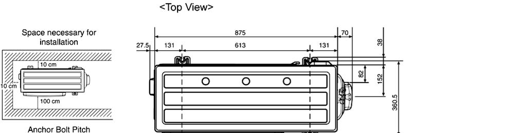
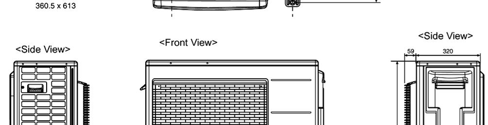
12 5.2.2 CU-RE24RKE 2
13 6. Refrigeration Cycle Diagram 6.. CS-RE8RKEW CU-RE8RKE INDOOR OUTDOOR LIQUID SIDE EXPANSION VALVE RECEIVER PIPE TEMP. SENSOR [EVA INLET] 2-WAY VALVE PIPE TEMP. SENSOR INTAKE TEMP. SENSOR PIPE TEMP. SENSOR AIR TEMP. SENSOR HEAT EXCHANGER (EVAPORATOR) HEAT EXCHANGER (CONDENSER) GAS SIDE STRAINER 3-WAY VALVE 4-WAY VALVE COMPRESSOR TEMP. SENSOR COMPRESSOR COOLING HEATING 3
14 6..2 CS-RE24RKEW CU-RE24RKE INDOOR OUTDOOR PIPE TEMP. SENSOR [EVA INLET] LIQUID SIDE 2-WAY VALVE RECEIVER STRAINER EXPANSION VALVE STRAINER PIPE TEMP. SENSOR INTAKE TEMP. SENSOR PIPE TEMP. SENSOR AIR TEMP. SENSOR HEAT EXCHANGER (EVAPORATOR) HEAT EXCHANGER (CONDENSER) GAS SIDE 3-WAY VALVE DISCHARGE MUFFLER 4-WAY VALVE COMPRESSOR TEMP. SENSOR COMPRESSOR COOLING HEATING 4
15 7. Block Diagram 7. CS-RE8RKEW CU-RE8RKE FUSE SINGLE PHASE POWER SUPPLY FUSE3 2 3 FUSE2 DB2 CT400 REACTOR DB 4-WAYS VALVE Q FUSE M P N U V W MS 3 ~ NTC TH CR3 RY-C RY-HOT RY-PWR RY-AC PTC PTC2 SC D46 D47 NTC TH2 DB3 NOISE FILTER SC (INDOOR UNIT) (OUTDOOR UNIT) L N M 5
16 7.2 CS-RE24RKEW CU-RE24RKE FUSE SINGLE PHASE POWER SUPPLY 2 3 FUSE2 DB2 SC RY-PWR RY-AC RY-HOT D47 REACTOR RY-C DB NTC TH2 DB3 FUSE M P N MS 3 ~ NOISE FILTER NTC TH SC (INDOOR UNIT) (OUTDOOR UNIT) L N M PTC REACTOR 4-WAYS VALVE 6
17 8. Wiring Connection Diagram 8. Indoor Unit ELECTRONIC CONTROLLER (MAIN) SW0 CN-RMT (WHT) 4 TO OUTDOOR UNIT TEMP. FUSE 02 C (3A) TERMINAL BOARD 2 3 GROUNDING TERMINAL YLW/GRN EVAPORATOR M FAN MOTOR BLK WHT RED GRN AC306 (BLK) AC303 (WHT) AC304 (RED) G30 (GRN) CN-FM (WHT) Y 7 B W BL 4 R FUSE30 T3.5A L250V COMMUNICATION CIRCUIT NOISE FILTER CIRCUIT RECTIFICATION CIRCUIT CN-DISP (YLW) CN-STM (WHT) 5 CN-STM2 (YLW) CN-TH (RED) 5 6 BR R O Y P BR R O Y P 0 t 5 5 M M PIPING TEMP. SENSOR 2 (THERMISTOR) 0 t PIPING TEMP. SENSOR (THERMISTOR) 0 t SUCTION TEMP. SENSOR (THERMISTOR) UP DOWN LOUVER MOTOR LEFT RIGHT LOUVER MOTOR REMARKS B : BLUE P: PINK BR: BROWN O: ORANGE BL: BLACK Y: YELLOW W: WHITE G: GREEN R: RED Y/G: YELLOW/GREEN 7 CN-DISP (WHT) ELECTRONIC CONTROLLER (DISPLAY & RECEIVER) W W W W W W W REMOTE CONTROLLER 7
18 t 0 t 0 t Outdoor Unit 8.2. CU-RE8RKE SINGLE PHASE POWER SUPPLY TO INDOOR UNIT (BLK) (WHT) (RED) YELLOW GROUNDING TERMINAL CABINET SIDE PLATE L YLW/GRN YLW/GRN N BLK CONTROL BOARD (BLK) BLK WHT 2 (WHT) WHT CONTROL BOARD 3 (RED) RED BLK WHT GRN GRN COM3 (RED) AC-BLK (BLACK) FUSE3 (20A 250V) AC-WHT (WHITE) FG0 (GREEN) LJP7 (GREEN) TERMINAL BOARD GRY L2-I (GRAY) COMMUNICATION CIRCUIT NOISE FILTER CIRCUIT PFC CIRCUIT REACTOR FUSE2 (T3.5A L250V) GRY L2-O (GRAY) RECTIFICATION CIRCUIT ELECTRONIC CONTROLLER RECTIFICATION CIRCUIT SWITCHING POWER SUPPLY CIRCUIT Q0 P N FUSE (T2.5A L250V) U V W (RED) (BLU) (YLW) CN-DCFM (WHITE) BLUE TRADE MARK RED COMP. TERMINAL REMARKS BLU: BLUE BLK: BLACK WHT: WHITE RED: RED YLW: YELLOW GRY: GRAY GRN: GREEN ORG: ORANGE YLW/GRN: YELLOW/GREEN RED BLU YLW RED RED BLU YLW MS 3 ~ COMPRESSOR CN-HOT (BLUE) RY-HOT 3 BLU ELECTRO-MAGNETIC COIL (4-WAYS VALVE) CN-EV (WHITE) 6 M ELECTRO-MAGNETIC COIL (EXPANSION VALVE) CN-TANK (WHITE) 3 COMP. TEMP. SENSOR (THERMISTOR) CN-TH (WHITE) 4 PIPING TEMP. SENSOR (THERMISTOR) 7 OUTDOOR AIR TEMP. SENSOR (THERMISTOR) BLK WHT BLU YLW M FAN MOTOR Resistance of Compressor Windings MODEL CU-RE8RKE CONNECTION 5RD32XBA2 U-V.897 Ω U-W.882 Ω V-W.907 Ω Note: Resistance at 20 C of ambient temperature. 8
19 8.2.2 CU-RE24RKE SINGLE PHASE POWER SUPPLY TO OUTDOOR UNIT TERMINAL BOARD BLK L WHT N TERMINAL BOARD 2 3 CABINET SIDE PLATE YLW/GRN YLW/GRN CONTROL BOARD BLK WHT RED ACL (BLACK) FUSE3 (25A 250V) ACN (WHITE) COM3 (RED) GRN FG (GREEN) NOISE FILTER CIRCUIT COMMUNICATION CIRCUIT CN-BLK (BLACK) CN-WHT (WHITE) CN-COM (YELLOW) ELECTRONIC CONTROLLER (NOISE FILTER) YELLOW BLUE RED TRADE MARK COMP. TERMINAL REMARKS BLU: BLUE BLK: BLACK WHT: WHITE RED: RED YLW: YELLOW GRY: GRAY GRN: GREEN ORG: ORANGE YLW/GRN: YELLOW/GREEN 4 BLK WHT WHT WHT WHT WHT ELECTRONIC CONTROLLER (MAIN) AC-BLK (BLACK) AC-WHT (WHITE) 4 CN-COM (YELLOW) REACTOR BLK GRY GRY BLK GRY GRY BLK L-I (GRAY) 4 WAY VALVE CIRCUIT L2-I (GRAY) FUSE2 T3.5A L250V 4 4 PFC CIRCUIT RECTIFICATION CIRCUIT REACTOR BLK L-O L2-O (BLACK) (BLACK) P Q0 U V N W RECTIFICATION CIRCUIT FUSE T2.5A L250V CN-FM (WHITE) CN-TH (WHITE) 4 CN-TANK (WHITE) CN-EV (WHITE) SWITCHING POWER SUPPLY CIRCUIT (RED) (BLUE) (YELLOW) CN-HOT (BLUE) RED BLU YLW RED 3 3 RED BLU YLW 4 BLK M WHT BLU YLW M MS 3 ~ COMPRESSOR FAN MOTOR OUTDOOR AIR TEMP. SENSOR (THERMISTOR) 0 t 0 t PIPING TEMP. SENSOR (THERMISTOR) 0 t COMP. TEMP. SENSOR (THERMISTOR) ELECTRO-MAGNETIC COIL (EXPANSION VALVE) ELECTRO-MAGNETIC COIL (4-WAYS VALVE) Resistance of Compressor Windings MODEL CU-RE24RKE CONNECTION 5KD240XAF2 U-V Ω U-W Ω V-W Ω Note: Resistance at 20 C of ambient temperature. 9
20 9. Electronic Circuit Diagram 9. Indoor Unit Sensor (Thermistor) Characteristics 60 2 Pipe Temp. Sensor Intake Air Temp. Sensor Resistance (kω) 5V 5V C3 0.µ 6V *R89 *R54 5V *R *C45 *C Temperature (ºC) REMOTE CONTROLLER TERMINAL BOARD 2 3 TO OUTDOOR UNIT TEMP. FUSE 02 C (3A) GROUNDING TERMINAL YLW/GRN EVAPORATOR M FAN MOTOR ELECTRONIC CONTROLLER (DISPLAY & RECEIVER) PCB20 5V_ IC Vout Vcc GND GND GND POWER (GREEN) 6 LED20 R /0W 5% CN-DISP (WHT) C20 47µ 6.3V C µ 6V TIMER (ORANGE) 7 LED202 R202 2k /0W 5% POWERFUL GND-A (ORANGE) 8 R203 LED203 QUIET 9 R204 (ORANGE) LED204 BLK AC306 (BLK) FUSE30 T3.5A L250V WHT RED AC303 (WHT) AC304 (RED) NOISE FILTER CIRCUIT IC03 GRN G30 (GRN) COMMUNICATION CIRCUIT IC05 Y 7 B W BL R CN-FM (WHT) 4 RECTIFICATION CIRCUIT ELECTRONIC CONTROLLER (MAIN) R62 5.0k *CN-RMT 2V VCC GND 2V VCC GND C25 µ 6V 2V R47 /2W 43 R46 /2W CN-STM WHITE 68 5% 68 5% BZ0 5V BZ 2V R30 k *CN-STM2 5V *CN-TH RED R6 20.0k C27 µ 6V *R63 *C28 5V R85 5.k *C47 *C48 BR R O M Y P 5 UP DOWN LOUVER MOTOR BR R O M Y P 5 LEFT RIGHT LOUVER MOTOR SUCTION TEMP. SENSOR (THERMISTOR) PIPING TEMP. SENSOR (THERMISTOR) PIPING TEMP. SENSOR 2 (THERMISTOR) t t t
21 9.2 Outdoor Unit 9.2. CU-RE8RKE SINGLE PHASE POWER SUPPLY TO INDOOR UNIT (BLK) (WHT) (RED) REACTOR GROUNDING TERMINAL CABINET SIDE PLATE L YLW/GRN YLW/GRN N BLK CONTROL BOARD (BLK) BLK WHT 2 (WHT) WHT 3 (RED) RED GRN COM3 (RED) AC-BLK (BLACK) FUSE3 (20A 250V) AC-WHT (WHITE) FG0 (GREEN) TERMINAL BOARD GRY L2-I (GRAY) COMMUNICATION CIRCUIT NOISE FILTER CIRCUIT FUSE2 (T3.5A L250V) GRY L2-O (GRAY) C46 µ 6.3V RECTIFICATION CIRCUIT 90 R0 5.8k 5V C45 µ 6.3V R00 5.0k C49 µ 0V 5V R k SWITCHING POWER SUPPLY CIRCUIT 3 CN-TANK CN-TH COMP. TEMP. SENSOR (THERMISTOR) (50kΩ 3950) OUTDOOR AIR TEMP. SENSOR (THERMISTOR) (5kΩ 3950) PIPING TEMP. SENSOR (THERMISTOR) (4.96kΩ 3800) CONTROL BOARD GRN LJP7 (GREEN) PFC CIRCUIT RECTIFICATION CIRCUIT Q0 P N U V W (RED) (BLU) (YLW) RED BLU YLW RED BLU YLW MS 3 ~ *D33 *D34 FUSE (T2.5A L250V) RED COMPRESSOR CN-HOT (BLUE) RY-HOT 3 *D35 *D36 *CN-EV BLU ELECTRO-MAGNETIC COIL (4-WAYS VALVE) M 3V *C84 CN-DCFM (WHITE) ELECTRONIC CONTROLLER 7 ELECTRO-MAGNETIC COIL (EXPANSION VALVE) BLK WHT BLU YLW M FAN MOTOR Sensor (Thermistor) Characteristics Outdoor Air Sensor 2 Outdoor Heat Exchanger Sensor Compressor Temp. Sensor (Thermistor) Characteristics Resistance (kω) Resistance (kω) Temperature ( o C) Temperature ( o C) 2
22 9.2.2 CU-RE24RKE SINGLE PHASE POWER SUPPLY TO OUTDOOR UNIT TERMINAL BOARD L N BLK WHT TERMINAL BOARD 2 3 CABINET SIDE PLATE YLW/GRN YLW/GRN CONTROL BOARD BLK WHT RED ACL (BLACK) FUSE3 (25A 250V) ACN (WHITE) COM3 (RED) R k /0W 5V R k /0W 52 G b c e GRN FG (GREEN) NOISE FILTER CIRCUIT COMMUNICATION CIRCUIT Q25 Q26 R427 47k /0W 4.7k 0k c e G CN-BLK (BLACK) CN-WHT (WHITE) CN-COM WHITE ELECTRONIC CONTROLLER (NOISE FILTER) b 5V G BLK WHT AC-BLK (BLACK) AC-WHT (WHITE) CN-COM (YELLOW) G V 5V R59 0k C63 000p 50V G5 REACTOR BLK GRY GRY BLK GRY GRY BLK L-I (GRAY) L2-I (GRAY) FUSE2 T3.5A L250V 4 4 PFC CIRCUIT REACTOR BLK L-O L2-O (BLACK) (BLACK) P Q N RECTIFICATION CIRCUIT FUSE T2.5A L250V (RED) (BLUE) U V (YELLOW) W CN-FM (WHITE) RED BLU YLW RED 3 3 RED BLU YLW 4 BLK M WHT BLU YLW 7 MS 3 ~ COMPRESSOR FAN MOTOR TANK TEMP. SENSOR (50kΩ 3950) OUTDOOR TEMP. SENSOR (5kΩ 3950) PIPE TEMP. SENSOR (4.96kΩ 3800) 3CN-TANK V 02 R k /0W % G5 CN-TH C49 µ 6.3V G5 R00 5.0k /0W % 5V 90 R0 5.8k /0W % C45 µ 6.3V G5 G5 G5 C46 µ 6.3V G2 D33 D34 D35 D36 CN-EV 4 WAY VALVE CIRCUIT 3V G2 C µ 25V RECTIFICATION CIRCUIT ELECTRONIC CONTROLLER (MAIN) SWITCHING POWER SUPPLY CIRCUIT CN-HOT (BLUE) 3 ELECTRO-MAGNETIC COIL (4-WAYS VALVE) EXPAND VALVE M Sensor (Thermistor) Characteristics Outdoor Air Sensor 2 Outdoor Heat Exchanger Sensor Compressor Temp. Sensor (Thermistor) Characteristics Resistance (kω) Resistance (kω) Temperature ( o C) Temperature ( o C) 22

 0.")
23 0. Printed Circuit Board 0. Indoor Unit 0.. Main Printed Circuit Board AC304 AC303 G30 AC306 CN-FM CN-RMT CN-STM2 CN-STM CN-DISP CN-TH JP (Random Auto Restart enable/disable) 0..2 Indicator Printed Circuit Board CN-DISP 23
 L2- CURRENT TRANSFORMER (CT) CN-HOT CN-DCFM COM3 CN-TANK CN-EV CN-TH AC-BLK AC-WHT")
24 0.2 Outdoor Unit 0.2. Main Printed Circuit Board CU-RE8RKE L-0 L2-0 POWER TRANSISTOR (IPM) L2- CURRENT TRANSFORMER (CT) CN-HOT CN-DCFM COM3 CN-TANK CN-EV CN-TH AC-BLK AC-WHT 24
25 CU-RE24RKE L-0 POWER TRANSISTOR (IPM) L2-0 CURRENT TRANSFORMER (CT) AC-WHT AC-BLK CN-HOT CN-COM CN-FM CN-TANK CN-TH CN-EV 25
26 0.2.2 Noise Filter Printed Circuit Board CU-RE24RKE CN-COM COM3 ACL CN-BLK ACN CN-WHT FG 26
27 65 mm or more. Installation Instruction. Select the Best Location.. Indoor Unit Do not install the unit in excessive oil fume area such as kitchen, workshop and etc. There should not be any heat source or steam near the unit. There should not be any obstacles blocking the air circulation. A place where air circulation in the room is good. A place where drainage can be easily done. A place where noise prevention is taken into consideration. Do not install the unit near the door way. Ensure the spaces indicated by arrows from the wall, ceiling, fence or other obstacles. Recommended installation height for indoor unit shall be at least 2.5 m...2 Outdoor Unit If an awning is built over the unit to prevent direct sunlight or rain, be careful that heat radiation from the condenser is not obstructed. There should not be any animal or plant which could be affected by hot air discharged. Keep the spaces indicated by arrows from wall, ceiling, fence or other obstacles. Do not place any obstacles which may cause a short circuit of the discharged air. If piping length is over the [piping length for additional gas], additional refrigerant should be added as shown in the table. Model Horse Power (HP) Piping si ze Gas Liquid RE9** * RE2*** RE5** *.0HP.5HP.75HP 9.52mm (3/8") 2.7mm 6.35mm RE8*** 2.0HP (/2") (/4") RE24** * 2.5HP 5.88m m (5/8") Std. Length (m) 5 Max. Elevation (m) Min. Piping Length (m) Max. Piping Length (m) Additional Refrigerant (g/m) Piping Length for add. gas (m) Indoor/Outdoor Unit Installation Diagram Piping direction (Front side) Right Right Rear Right Left Left bottom Rear Left bottom 50 mm or more (Left and right are identical) Insulation of piping connections Carry out insulation after checking for gas leaks and secure with vinyl tape. Vinyl tape Remote control holder fixing screws 6 Remote control 3 It is advisable to avoid more than 2 blockage directions. For better ventilation & multiple-outdoor installation, please consult authorized dealer/specialist. Remote control holder 5 Attention not to bend up drain hose Attaching the remote control holder to the wall 00 mm or more 000 mm or more 00 mm or more 300 mm or more Installation parts you should purchase ( ) Installation plate Bushing-Sleeve ( ) Sleeve ( ) Putty ( ) (Gum Type Sealer) Bend the pipe as closely on the wall as possible, but be careful that it doesn t break. Vinyl tape (wide) ( ) Apply after carrying out a drainage test. To carry out the drainage test, remove the air filters and pour water into the heat exchanger. Saddle ( ) Power supply cord ( ) Connection cable Liquid side piping ( ) Gas side piping ( ) Additional drain hose ( ) This illustration is for explanation purposes only. The indoor unit will actually face a different way Example: For RE9*** If the unit is installed at 0 m distance, the quantity of additional refrigerant should be 50 g... (0-7.5) m 20 g/m = 50 g. 27
28 .2 Indoor Unit.2. How to Fix Installation Plate The mounting wall shall be strong and solid enough to prevent if from the vibration. Wall Wall More than More than Wall Indoor unit 2 screw More than mm Measuring Tape 24.5 mm 6 5 Installation plate 24.5 mm 28 mm For best strength of INDOOR unit installation, it is highly recommended to locate at 5 position as shown. 28 mm Model Dimension RE9***, RE2***, RE5*** or 490 mm 82 mm 439 mm 432 mm 43 mm 95 mm RE8***, RE24*** 590 mm 82 mm 539 mm 532 mm 69 mm 29 mm The center of installation plate should be at more than at right and left of the wall. The distance from installation plate edge to ceiling should more than. From installation plate center to unit s left side is. From installation plate center to unit s right side is. B : For left side piping, piping connection for liquid should be about from this line. : For left side piping, piping connection for gas should be about from this line.. Mount the installation plate on the wall with 5 screws or more (at least 5 screws). (If mounting the unit on the concrete wall, consider using anchor bolts.) o Always mount the installation plate horizontally by aligning the marking-off line with the thread and using a level gauge. 2. Drill the piping plate hole with ø70 mm hole-core drill. o Line according to the left and right side of the installation plate. The meeting point of the extended line is the center of the hole. Another method is by putting measuring tape at position as shown in the diagram above. The hole center is obtained by measuring the distance namely 28 mm for left and right hole respectively. o Drill the piping hole at either the right or the left and the hole should be slightly slanting to the outdoor side..2.2 To Drill a Hole in the Wall and Install a Sleeve of Piping Insert the piping sleeve to the hole. 2 Fix the bushing to the sleeve. 3 Cut the sleeve until it extrudes about 5 mm from the wall. Indoor Sleeve for tube assembly Wall Outdoor 5 mm CAUTION When the wall is hollow, please be sure to use the sleeve for tube assembly to prevent dangers caused by mice biting the connection cable. 4 Finish by sealing the sleeve with putty or caulking compound at the final stage. ø70 mm through hole Approx. 5-7 mm Bushing for tube assembly Putty or caulking compound 28
29 PUSH PUSH PUSH PUSH.2.3 Indoor Unit Installation Do not turn over the unit without it s shock absorber during pull out the piping. It may cause intake grille damage. Use shock absorber during pull out the piping to protect the intake grille from damage. pull out the piping pull out the piping Piping Piping Intake grille Shock absorber.2.3. For the right rear piping Step- Step-2 Step-3 Step-4 Pull out the Indoor piping Install the Indoor Unit Secure the Indoor Unit Insert the connection cable For the right and right bottom piping Step- Step-2 Step-3 Step-4 Pull out the Indoor piping Install the Indoor Unit Insert the connection cable Secure the Indoor Unit For the embedded piping Step- Step-2 Step-3 Step-4 Step-5 Replace the drain hose Bend the embedded piping Use a spring bender or equivalent to bend the piping so that the piping is not crushed. Pull the connection cable into Indoor Unit The inside and outside connection cable can be connected without removing the front grille. Cut and flare the embedded piping When determining the dimensions of the piping, slide the unit all the way to the left on the installation plate. Refer to the section Cutting and flaring the piping. Install the Indoor Unit Step-6 Connect the piping Please refer to Connecting the piping column in outdoor unit section. (Below steps are done after connecting the outdoor piping and gas-leakage confirmation.) Step-7 Insulate and finish the piping Step-8 Please refer to Insulation of piping connection column as mentioned in indoor/outdoor unit installation. Secure the Indoor Unit Right Rear piping Tape it with piping in a position as mentioned in Fig. below. Piping Drain hose Cover for the right piping Cover for the bottom piping How to keep the cover In case of the cover is cut, keep the cover at the rear of chassis as shown in the illustration for future reinstallation. (Left, right and 2 bottom covers for piping.) Right and Right Bottom piping Install the indoor unit Hook the indoor unit onto the upper portion of installation plate. (Engage the indoor unit with the upper edge of the installation plate). Ensure the hooks are properly seated on the installation plate by moving it in left and right. Secure the Indoor Unit marking Tape it with piping in a position as mentioned in Fig. below. Piping Drain hose Cover for the right piping. Press the lower left and right side of the unit against the installation plate until hooks engages with their slot (sound click). Insert the connection cable About mm Guide surface Cover Cover for the for the bottom piping left piping Cover for the bottom piping Indoor unit Unit s hook Cover for piping Cover for the left piping To take out the unit, push the marking at the bottom unit, and pull it slightly towards you to disengage the hooks from the unit. Connection cable Gas side piping Liquid side piping Connection cable Drain hose Hooks at installation plate Sleeve for piping hole Piping Drain hose Installation plate (This can be used for left rear piping and left bottom piping also.) 29
30 Replace the drain hose Rear view for left piping installation Drain cap Drain hose Drain hose Connection cable Adjust the piping slightly downwards. Piping Drain hose Sleeve for piping hole Connection cable More than 950 mm (.0 ~.75HP) or More than 50 mm (2.0 ~ 2.5HP) How to pull the piping and drain hose out, in case of the embedded piping. Apply putty or caulking material to seal the wall opening. PVC tube for drain hose (VP-20) More than 700 mm More than 950 mm (.0 ~.75HP) or More than 50 mm (2.0 ~ 2.5HP) More than 470 mm Connection cable Piping Drain hose from main unit PVC tube (VP-65) for piping and connection cable PVC tube for drain hose (VP-30) In case of left piping how to insert the connectioncable and drain hose. Drain hose 45 PVC tube for drain hose Indoor unit Cable Piping Cable Piping (For the right piping, follow the same procedure) 00 mm (.0 ~.75HP) or 72 mm (2.0 ~ 2.5HP).2.4 Connect the Cable to the Indoor Unit The inside and outside connection cable can be connected without removing the front grille. 2 Connection cable between indoor unit and outdoor unit shall be approved polychloroprene sheathed 4.5 mm 2 flexible cord, type designation IEC 57 or heavier cord. Do not use joint connection cable. Replace the wire if the existing wire (from concealed wiring, or otherwise) is too short. Allowable connection cable length of each indoor unit shall be 30 m or less. 3 Bind all the indoor and outdoor connection cable with tape and route the connection cable via the escapement. 4 Remove the tapes and connect the connection cable between indoor unit and outdoor unit according to the diagram below. 30
31 Tape Terminal Board Terminals on the indoor unit Colour of wires Terminals on the outdoor unit Connection cable Indoor & outdoor Connection cable Earth Wire longer than others AC wires for safety reason Escapement Holder Recommended length (mm) Recommended length (mm) a b c d Indoor & outdoor Connection cable Outdoor unit WARNING This equipment must be properly earthed. Note: Secure the connection cable onto the control board with the holder. Ensure the colour of wires of outdoor unit and the terminal Nos. are the same to the indoor s respectively. Earth wire shall be Yellow/Green (Y/G) in colour and longer than other AC wires for safety reason. WIRE STRIPPING, CONNECTING REQUIREMENT No loose strand when inserted 0 ± mm Wire stripping Indoor/outdoor connection terminal board 5 mm or more (gap between wires) Conductor fully inserted Conductor over inserted Conductor not fully inserted ACCEPT PROHIBITED PROHIBITED WARNING RISK OF FIRE JOINING OF WIRES MAY CAUSE OVERHEATING AND FIRE. OR Do not joint wires OR OR Use complete wire without joining. Use approved socket and plug with earth pin. Wire connection in this area must follow to national wiring rules. 3
32 .2.4. Cutting and flaring the piping Please cut using pipe cutter and then remove the burrs. 2 Remove the burrs by using reamer. If burrs are not removed, gas leakage may be caused. Turn the piping end down to avoid the metal powder entering the pipe. 3 Please make flare after inserting the flare nut onto the copper pipes. Improper flaring Pipe Reamer Bar Handle Yoke Core Bar mm Inclined Surface Cracked Uneven damaged thickness. To cut Point down 2. To remove burrs Clamp handle 3. To flare Red arrow mark Copper pipe When properly flared, the internal surface of the flare will evenly shine and be of even thickness. Since the flare part comes into contact with the connections, carefully check the flare finish. 32
33 .3 Outdoor Unit.3. Install the Outdoor Unit After selecting the best location, start installation according to Indoor/Outdoor Unit Installation Diagram. Fix the unit on concrete or rigid frame firmly and horizontally by bolt nut (ø0 mm). 2 When installing at roof, please consider strong wind and earthquake. Please fasten the installation stand firmly with bolt or nails. A B C Model A B C D RE9*** 570 mm 05 mm 8.5 mm 320 mm RE2*** RE5*** 540 mm 60 mm 8.5 mm 330 mm RE8*** RE24*** 63 mm 30 mm 24 mm mm D.3.2 Connect the Piping.3.2. Connecting the Piping to Indoor Please make flare after inserting flare nut (locate at joint portion, of tube assembly) onto the copper pipe. (In case of using long piping) Connect the piping Align the center of piping and sufficiently tighten the flare nut with fingers. Further tighten the flare nut with torque wrench in specified torque as stated in the table. Do not overtighten, overtightening may cause gas leakage. Piping size Torque 6.35 mm (/4 ) [8 N m (.8 kgf m)] 9.52 mm (3/8 ) [42 N m (4.3 kgf m)] 2.7 mm (/2 ) [55 N m (5.6 kgf m)] 5.88 mm (5/8 ) [65 N m (6.6 kgf m)] 9.05 mm (3/4 ) [00 N m (0.2 kgf m)] Connecting the Piping to Outdoor Decide piping length and then cut by using pipe cutter. Remove burrs from cut edge. Make flare after inserting the flare nut (located at valve) onto the copper pipe. Align center of piping to valves and then tighten with torque wrench to the specified torque as stated in the table. Spanner or Wrench Torque wrench Connecting the Piping to Outdoor Multi Decide piping length and then cut by using pipe cutter. Remove burrs from cut edge. Make flare after inserting the flare nut (locate at valve) onto the copper pipe. Align center of piping to valve and then tighten with torque wrench to the specified torque as stated in the table. Auxiliary pipe (male side) Hall Union Liquid side Flare Nut Connection pipe (female side) 33
34 * For Gas side piping please refer table and diagram below Outdoor Multi combination model CS-RE9***, CS-RE2*** CU-2E5***, CU-2E8***, CU-2RE5***, CU-2RE8***, CU-3E8***, CU-4E23***, CU-4E27***, CU-5E34*** Pipe size (refer to diagram) 2 Auxiliary pipe (male side) Auxiliary pipe (male side) Hall Union Hall Union Packing Pipe size reducer (CZ-MAP) Flare Nut Connection pipe (female side) Flare Nut Gas side Connection pipe (female side) CS-RE5***, CS-RE8*** CU-3E8***, CU-4E23***, CU-4E27***, CU-5E34*** 2 (CZ-MAP) 3 Pipe size reducer Hall Union (CZ-MA3P) Flare Nut Packing Hall Union CS-RE24*** CU-4E27***, CU-5E34*** 3 (CZ-MA2P) & (CZ-MA3P) Auxiliary pipe (male side) (Indoor) Packing Connection pipe (female side) Pipe size expander (CZ-MA2P) Auxiliary pipe (male side) (Outdoor).3.3 Evacuation of the Equipment WHEN INSTALLING AN AIR CONDITIONER, BE SURE TO EVACUATE THE AIR INSIDE THE INDOOR UNIT AND PIPES in the following procedure. Indoor unit Liquid side Two-way valve Outdoor unit Close Gas side OPEN Three-way valve Close Lo Hi Vacuum pump CLOSE Connect a charging hose with a push pin to the Low side of a charging set and the service port of the 3-way valve. o Be sure to connect the end of the charging hose with the push pin to the service port. 2 Connect the center hose of the charging set to a vacuum pump. 3 Turn on the power switch of the vacuum pump and make sure that the needle in the gauge moves from 0 cmhg (0 MPa) to -76 cmhg (-0. MPa). Then evacuate the air approximately ten minutes. 4 Close the Low side valve of the charging set and turn off the vacuum pump. Make sure that the needle in the gauge does not move after approximately five minutes. Note: BE SURE TO TAKE THIS PROCEDURE IN ORDER TO AVOID REFRIGERENT GAS LEAKAGE. 5 Disconnect the charging hose from the vacuum pump and from the service port of the 3-way valve. 6 Tighten the service port caps of the 3-way valve at a torque of 8 N m with a torque wrench. 7 Remove the valve caps of both of the 2-way valve and 3-way valve. Position both of the valves to OPEN using a hexagonal wrench (4 mm). 34
35 8 Mount valve caps onto the 2-way valve and the 3-way valve. o Be sure to check for gas leakage.. If gauge needle does not move from 0 cmhg (0 MPa) to -76 cmhg (-0. MPa), in the step above take the following measure: - If the leak stops when the piping connections are tightened further, continue working from step. - If the leak does not stop when the connections are retightened, repair location of leak. - Do not release refrigerant during piping work for installation and reinstallation. - Take care of the liquid refrigerant, it may cause frostbite..3.4 Connect the Cable to the Outdoor Unit. Remove the control board cover from the unit by loosening the screw. 2. Cable connection to the power supply through Isolating Devices (Disconnecting means). Connect approved type polychloroprene sheathed power supply cord 3.5 mm 2 (.0 ~.75HP), mm 2 (2.0 ~ 2.5HP) type designation IEC 57 or heavier cord to the terminal board, and connect the others end of the cord to Isolating Devices (Disconnecting means). Do not use joint power supply cord. Replace the wire if the existing wire (from concealed wiring, or otherwise) is too short. In unavoidable case, joining of power supply cord between isolating devices and terminal board of air conditioner shall be done by using approved socket and plug with earth pin rated 5/6A (.0 ~.75HP) or 6A (2.0HP) or 20A (2.5HP). Wiring work to both socket and plug must follow to national wiring standard. 3. Connection cable between indoor unit and outdoor unit shall be approved polychloroprene sheathed 4.5 mm 2 flexible cord, type designation IEC 57 or heavier cord. Do not use joint connection cable. Replace the wire if the existing wire (from concealed wiring, or otherwise) is too short. Allowable connection cable length of each indoor unit shall be 30 mm or less. 4. Connect the power supply cord and connection cable between indoor unit and outdoor unit according to the diagram below. Terminals on the indoor unit Colour of wires (connection cable) Terminals on the outdoor unit (Power supply cord) Terminals on the isolating devices (Disconnecting means) 2 3 L N 2 3 (L) (N) 5. Secure the power supply cord and connection cable onto the control board with the holder. 6. Attach the control board cover back to the original position with screw. 7. For wire stripping and connection requirement, refer to instruction.2.4 of indoor unit. Earth wire longer than others AC wires for safety reason Power supply cord Isolating Devices Indoor & outdoor Connection cable Indoor unit WARNING Terminal Board Earth wire longer than others AC wires for safety reason Holder This equipment must be properly earthed. Note: Isolating Devices (Disconnecting means) should have minimum 3.0 mm contact gap. Earth wire shall be Yellow/Green (Y/G) in colour and longer than other AC wires for safety reason..3.5 Piping Insulation Please carry out insulation at pipe connection portion as mentioned in Indoor/Outdoor Unit Installation Diagram. Please wrap the insulated piping end to prevent water from going inside the piping. 2 If drain hose or connecting piping is in the room (where dew may form), please increase the insulation by using POLY-E FOAM with thickness 6 mm or above. 35

36 2. Operation and Control 2. Basic Function Inverter control, which equipped with a microcomputer in determining the most suitable operation mode as time passes, automatically adjusts output power for maximum comfort always. In order to achieve the suitable operation mode, the microcomputer maintains the set temperature by measuring the temperature of the environment and performing temperature shifting. The compressor at outdoor unit is operating following the frequency instructed by the microcomputer at indoor unit that judging the condition according to internal setting temperature and intake air temperature. 2.. Internal Setting Temperature Once the operation starts, remote control setting temperature will be taken as base value for temperature shifting processes. These shifting processes are depending on the air conditioner settings and the operation environment. The final shifted value will be used as internal setting temperature and it is updated continuously whenever the electrical power is supplied to the unit Cooling Operation Thermostat control Compressor is OFF when Intake Air Temperature - Internal Setting Temperature < -.5 C continue for 3 minutes. When compressor is OFF (Thermostat OFF) and AUTO FAN is set the fan will stop periodically. Compressor is ON after waiting for 3 minutes, if the Intake Air Temperature - Internal Setting Temperature > Compressor OFF point Soft Dry Operation Thermostat control Compressor is OFF when Intake Air Temperature - Internal Setting Temperature < -2.0 C continue for 3 minutes. When compressor is OFF (Thermostat OFF) and AUTO FAN is set the fan will stop periodically. Compressor is ON after waiting for 3 minutes, if the Intake Air Temperature - Internal Setting Temperature > Compressor OFF point Heating Operation Thermostat control Compressor is OFF when Intake Air Temperature - Internal Setting Temperature > +2.0 C continued for 3 minutes. Compressor is ON after waiting for 3 minutes, if the Intake Air Temperature - Internal Setting Temperature < Compressor OFF point. 36
37 2..5 Automatic Operation This mode can be set using remote control and the operation is decided by remote control setting temperature, remote control operation mode and indoor intake air temperature. During operation mode judgment, indoor fan motor (with speed of Lo-) is running for 30 seconds to detect the indoor intake air temperature. Every 0 minutes, the indoor temperature is judged. For the st judgment If indoor intake temperature - remote control setting temperature 2 C, COOL mode is decided. 2 If -2 C indoor intake temperature - remote control setting temperature < 2 C, DRY mode is decided. 3 If indoor intake temperature - remote control setting temperature < -2 C, HEAT mode is decided. For the 2nd judgment onwards If indoor intake temperature - remote control setting temperature 3 C, if previous operate in DRY mode, then continue in DRY mode. otherwise COOL mode is decided. 2 If -2 C indoor intake temperature - remote control setting temperature < 3 C, maintain with previous mode. 3 If indoor intake temperature - remote control setting temperature < -2 C, HEAT mode is decided Indoor Fan Motor Operation A. Basic Rotation Speed (rpm) i. Manual Fan Speed [Cooling, Dry] Fan motor s number of rotation is determined according to remote control setting. Remote Control Tab (rpm) Hi Me+ Me Me- Lo [Heating] Fan motor s number of rotation is determined according to remote control setting. Remote Control Tab (rpm) Shi Me+ Me Me- Lo ii. Auto Fan Speed [Cooling, Dry] According to room temperature and setting temperature, indoor fan speed is determined automatically. When set temperature is not achieved, the indoor fan will operate according to pattern below. When set temperature achieved, the fan speed will be fixed. 37
38 [Heating] According to indoor pipe temperature, automatic heating fan speed is determined as follows. B. Feedback control Immediately after the fan motor started, feedback control is performed once every second. During fan motor on, if fan motor feedback 2550 rpm or < 50 rpm continue for 0 seconds, then fan motor error counter increase, fan motor is then stop and restart. If the fan motor counter becomes 7 times, then H9 - fan motor error is detected. Operation stops and cannot on back Outdoor Fan Motor Operation Outdoor fan motor is operated with one fan speed only. It starts when compressor starts operation and it stops 30 seconds after compressor stops operation. 2.2 Airflow Direction There are two types of airflow, vertical airflow (directed by horizontal vane) and horizontal airflow (directed by vertical vanes). 2 Control of airflow direction can be automatic (angles of direction is determined by operation mode, heat exchanger temperature and intake air temperature) and manual (angles of direction can be adjusted using remote control) Vertical Airflow Cooling Dry Operation Mode Auto Manual Auto Manual Vane Angle ( ) Usual (Ventilation) 5 ~ 35 Control with dew 5 ~ 35 Usual (Ventilation) Control with dew Usual 5 ~ 35 Control with dew 5 ~ 35 Usual Control with dew Heating Manual Usual Automatic vertical airflow direction can be set using remote control; the vane swings up and down within the angles as stated above. For heating mode operation, the angle of the vane depends on the indoor heat exchanger temperature as Figure below. It does not swing during fan motor stop. When the air conditioner is stopped using remote control, the vane will shift to close position. 38
39 2 Manual vertical airflow direction can be set using remote control; the angles of the vane are as stated above and the positions of the vane are as Figure 2 below. When the air conditioner is stopped using remote control, the vane will shift to close position Horizontal Airflow Automatic horizontal airflow direction can be set using remote control; the vane swings left and right within the angles as stated below. It does not swing during fan motor stop. For heating mode operation, the angle of the vane depends on the indoor heat exchanger temperature as Figure below. Operation Mode Vane Angle ( ) A 68 ~ 5 Heating, with heat exchanger temperature B 90 Cooling and Soft Dry 68 ~ 5 2 Manual horizontal airflow direction can be set using remote control; the angles of the vane are as stated below and the positions of the vane are as Figure 2 above. Pattern Airflow Direction Patterns at Remote Control Vane Angle ( )
40 2.3 Timer Control There are 2 sets of ON and OFF timer available to turn the unit ON or OFF at different preset time. If more than one timer had been set, the upcoming timer will be displayed and will activate in sequence ON Timer Control ON timer and ON timer 2 can be set using remote control, the unit with timer set will start operate earlier than the setting time. This is to provide a comfortable environment when reaching the set ON time. 60 minutes before the set time, indoor (at fan speed of Lo-) and outdoor fan motor start operate for 30 seconds to determine the indoor intake air temperature and outdoor air temperature in order to judge the operation starting time. From the above judgment, the decided operation will start operate earlier than the set time as shown below OFF Timer Control OFF timer and OFF timer 2 can be set using remote control, the unit with timer set will stop operate at set time. 2.4 Auto Restart Control When the power supply is cut off during the operation of air conditioner, the compressor will re-operate within three to four minutes (there are 0 patterns between 2 minutes 58 seconds and 3 minutes 52 seconds to be selected randomly) after power supply resumes. 2 This type of control is not applicable during ON/OFF Timer setting. 3 This control can be omitted by short the circuit of JP at indoor unit printed circuit board. 2.5 Indication Panel LED POWER TIMER POWERFUL QUIET Color Green Orange Orange Orange Light ON Operation ON Timer Setting ON Powerful ON Quiet ON Light OFF Operation OFF Timer Setting OFF Powerful OFF Quiet OFF Note: If POWER LED is blinking, the possible operation of the unit are Hot Start, during Deice operation, operation mode judgment, or ON timer sampling. If Timer LED is blinking, there is an abnormality operation occurs. 40
41 2.6 Quiet Operation (Cooling Mode/Cooling Area of Dry Mode) A. Purpose To provide quiet cooling operation compare to normal operation. B. Control condition a. Quiet operation start condition o When POWERFUL/QUIET button at remote control is pressed twice. QUIET LED illuminates (low intensity). b. Quiet operation stop condition When one of the following conditions is satisfied, quiet operation stops: a. POWERFUL/QUIET button is pressed again. b. Stop by OFF/ON switch. c. Timer off activates. 2 When quiet operation is stopped, operation is shifted to normal operation with previous setting. 3 When fan speed is changed, quiet operation is shifted to quiet operation of the new fan speed. 4 When operation mode is changed, quiet operation is shifted to quiet operation of the new mode. 5 During quiet operation, if timer on activates, quiet operation maintains. 6 After off, when on back, quiet operation is not memorized. C. Control contents Fan speed is changed from normal setting to quiet setting of respective fan speed. 2 Fan speed for quiet operation is reduced from setting fan speed. 2.7 Quiet Operation (Heating) A. Purpose To provide quiet heating operation compare to normal operation. B. Control condition a. Quiet operation start condition o When POWERFUL/QUIET button at remote control is pressed. UIET LED illuminates. b. Quiet operation stop condition When one of the following conditions is satisfied, quiet operation stops: a. POWERFUL/QUIET button is pressed again. b. Stop by OFF/ON switch. c. Timer off activates. 2 When quiet operation is stopped, operation is shifted to normal operation with previous setting. 3 When fan speed is changed, quiet operation is shifted to quiet operation of the new fan speed. 4 When operation mode is changed, quiet operation is shifted to quiet operation of the new mode. 5 During quiet operation, if timer on activates, quiet operation maintains. 6 After off, when on back, quiet operation is not memorized. C. Control contents a. Fan Speed manual Fan speed is changed from normal setting to quiet setting of respective fan speed. 2 Fan speed for quiet operation is reduced from setting fan speed. b. Fan Speed Auto Indoor FM RPM depends on pipe temp sensor of indoor heat exchanger. 2.8 Powerful Mode Operation When the powerful mode is selected, the internal setting temperature will shift lower up to 2 C (for Cooling/Soft Dry) or higher up to 3.5 C (for Heating) than remote control setting temperature for 20 minutes to achieve the setting temperature quickly. 4
42 3. Protection Control 3. Protection Control For All Operations 3.. Time Delay Safety Control o The compressor will not start for three minutes after stop of operation. o This control is not applicable if the power supply is cut off and on again or after 4-way valve deices condition Total Running Current Control When the outdoor unit total running current (AC) exceeds X value, the frequency instructed for compressor operation will be decreased. 2 If the running current does not exceed X value for five seconds, the frequency instructed will be increased. 3 However, if total outdoor unit running current exceeds Y value, compressor will be stopped immediately for three minutes. Operation Mode RE8RKE RE24RKE X (A) Y (A) X (A) Y (A) Cooling / Soft Dry (A) Cooling / Soft Dry (B) Cooling / Soft Dry (C) Heating The first 30 minutes of cooling operation, (A) will be applied RE8RK RE24RK 3..3 IPM (Power transistor) Prevention Control Overheating Prevention Control o When the IPM temperature rises to 20 C (RE8RK) and 0 C (RE24RK), compressor operation will stop immediately. o Compressor operation restarts after three minutes the temperature decreases to 0 C (RE8RK) and 95 C (RE24RK). o If this condition repeats continuously 4 times within 20 minutes, timer LED will be blinking ( F96 is indicated). DC Peak Current Control o When electric current to IPM exceeds set value of 30.0 ± 5.0 A, the compressor will stop operate. Then, operation will restart after three minutes. o If the set value is exceeded again more than 30 seconds after the compressor starts, the operation will restart after one minute. o If the set value is exceeded again within 30 seconds after the compressor starts, the operation will restart after one minute. If this condition repeats continuously for seven times, all indoor and outdoor relays will be cut off, timer LED will be blinking ( F99 is indicated). 42
43 3..4 Compressor Overheating Prevention Control Instructed frequency for compressor operation will be regulated by compressor top temperature. The changes of frequency are as below figure. If compressor discharge temperature exceeds 07 C (RE8RK) and 2 C (RE24RK), compressor will be stop, occurs 4 times per 20 minutes, timer LED will be blinking ( F97 is to be confirmed). R E8RK RE24RK 3..5 Low Pressure Prevention Control (Gas Leakage Detection) Control start conditions o For 5 minutes, the compressor continuously operates and outdoor total current is between.38a and.65a (RE8RK only). o For 5 minutes, the compressor continuously operates and outdoor total current is between.88a and 2.85A (Cooling), 2.85A and 3.57A (Heating) (RE24RK only). o During Cooling and Soft Dry operations: Indoor suction temperature indoor piping temperature is below 4 C. o During Heating operations: Indoor piping temperature indoor suction is under 5 C. Control contents o o Compressor stops (and restart after 3 minutes). If the conditions above happen 2 times within 20 minutes, the unit will: Stop operation Timer LED blinks and F9 indicated Low Frequency Protection Control When the compressor operate at frequency lower than 24 Hz (RE8RK) and 20 Hz (RE24RK) continued for 20 minutes, the operation frequency will be changed to 23 Hz (RE8RK) and 2 Hz (RE24RK) for 2 minutes Low Frequency Protection Control 2 When all below conditions comply, the compressor frequency will change to lower frequency. Temperature, T, for: Cooling / Soft Dry Heating Indoor intake air ( C) T < 4 or T 30 T < 4 or T 28 Outdoor air ( C) T < 3 or T 38 T < 4 or T 24 Indoor heat exchanger ( C) T < 30 T 0 43
44 3.2 Protection Control For Cooling & Soft Dry Operation 3.2. Outdoor Air Temperature Control The compressor operating frequency is regulated in accordance to the outdoor air temperature as shown in the diagram below. This control will begin minute after the compressor starts. Compressor frequency will adjust base on Outdoor Air Temperature. The compressor will be stopped to avoid compressor overloading. COMP. ON -0 C -2 C COMP. OFF Cooling Overload Control Outdoor air temperature Pipe temperature limitation / restriction (RE24RK only) o Detects the Outdoor pipe temperature and carry out below restriction/limitation (Limit the compressor Operation frequency) o The compressor stop if outdoor pipe temperature exceeds 63 C (RE8RK) and 65 C (RE24RK). o If the compressor stops 4 times in 20 minutes, Timer LED blinking (F95: outdoor high pressure rise protection) Dew Prevention Control To prevent dew formation at indoor unit discharge area. 2 This control activated if: o Outdoor air temperature and Indoor pipe temperature judgment by microcontroller if fulfilled. o When Cooling or Dry mode is operated more than 20 minutes or more. 3 This control stopped if: o Compressor stopped. o Remote control setting changed. (fan speed / temperature) o Outdoor air temperature and indoor intake temperature changed. 4 Fan speed will be adjusted accordingly in this control Freeze Prevention Control When indoor heat exchanger temperature is lower than 0 C continuously for six minutes, compressor will stop operating. 2 Compressor will resume its operation three minutes after the indoor heat exchanger is higher than 5 C. 3 At the same time, indoor fan speed will be higher than during its normal operation. 4 If indoor heat exchanger temperature is higher than 5 C for five minutes, the fan speed will return to its normal operation. 44
45 3.2.5 Freeze Prevention Control 2 Control start conditions o During Cooling operation and soft dry operation During thermo OFF condition, indoor intake temperature is less than 0 C or Compressor stops for freeze prevention control o Either one of the conditions above occurs 5 times in 60 minutes. 2 Control contents o Operation stops. o Timer LED blinks and H99 indicated Odor Cut Control To reduce the odor released from the unit. o Start Condition AUTO FAN Speed is selected during COOL or DRY operation. During freeze prevention control and timer preliminary operation, this control is not applicable. o Control content Depends on compressor conditions:. Compressor OFF Compressor ON. The indoor unit fan stops temporarily and then starts to blow at minimum airflow for 30 seconds. 2. Compressor ON Compressor OFF. The indoor unit fan stops for 90 seconds and then blows at minimum airflow for 20 seconds. 3.3 Protection Control For Heating Operation 3.3. Intake Air Temperature Control Compressor will operate at limited frequency if indoor intake air temperature is 30 C or above Outdoor Air Temperature Control The maximum current value is regulated when the outdoor air temperature rises above 4 C in order to avoid compressor overloading. The compressor will be stopped to avoid compressor overloading. COMP. ON -5 C -7 C COMP. OFF Outdoor air temperature 45
46 3.3.3 Overload Protection Control The compressor operating frequency is regulated in accordance to indoor heat exchanger temperature as shown in below figures. If the heat exchanger temperature exceeds 60 C, compressor will stop (RE8RK). Indoor Heat Exchanger Temp. RE8RK RE24RK Cold Draught Prevention Control When indoor pipe temperature is low, cold draught operation starts where indoor fan speed will be reduced Deice Operation When outdoor pipe temperature and outdoor air temperature is low, deice operation start where indoor fan motor and outdoor fan motor stop and operation LED blinks. 46

47 4. Servicing Mode 4. Auto OFF/ON Button AUTO OPERATION MODE The Auto Operation will be activated immediately once the Auto OFF/ON button is pressed. This operation can be used to operate air conditioner with limited function if remote control is misplaced or malfunction. 2 TEST RUN OPERATION (FOR PUMP DOWN/SERVICING PURPOSE) The Test Run operation will be activated if the Auto OFF/ON button is pressed continuously for more than 5 seconds. A beep sound will occur at the fifth seconds, in order to identify the starting of Test Run operation (Forced cooling operation). Within 5 minutes after Forced cooling operation start, the Auto OFF/ON button is pressed for more than 5 seconds. A 2 beep sounds will occur at the fifth seconds, in order to identify the starting of Forced heating operation. The Auto OFF/ON button may be used together with remote control to set / change the advance setting of air conditioner operation. 3 REMOTE CONTROL NUMBER SWITCH MODE The Remote Control Number Switch Mode will be activated if the Auto OFF/ON button is pressed continuously for more than seconds (3 beep sounds will occur at th seconds to identify the Remote Control Number Switch Mode is in standby condition) and press AC RESET button and then press any button at remote control to transmit and store the desired transmission code to the EEPROM. There are 4 types of remote control transmission code could be selected and stored in EEPROM of indoor unit. The indoor unit will only operate when received signal with same transmission code from remote control. This could prevent signal interference when there are 2 or more indoor units installed nearby together. To change remote control transmission code, short or open jumpers at the remote control printed circuit board. JB JA Remote Control Printed Circuit Board Jumper A (JA) Jumper B (JB) Remote Control No. Short Open A (Default) Open Open B Short Short C Open Short D During Remote Control Number Switch Mode, press any button at remote control to transmit and store the transmission code to the EEPROM. 47
48 4 REMOTE CONTROL RECEIVING SOUND OFF/ON MODE The Remote Control Receiving Sound OFF/ON Mode will be activated if the Auto OFF/ON button is pressed continuously for more than 6 seconds (4 beep sounds will occur at 6th seconds to identify the Remote Control Receiving Sound Off/On Mode is in standby condition) and press AC Reset button at remote control. Press Auto OFF/ON button to toggle remote control receiving sound. - Short beep : Turn OFF remote control receiving sound. - Long beep : Turn ON remote control receiving sound. After Auto OFF/ON button is pressed, the 20 seconds counter for Remote Control Receiving Sound OFF/ON Mode is restarted. 4.2 Remote Control Button 4.2. SET BUTTON To check remote control transmission code and store the transmission code to EEPROM. o Press SET button for more than 0 seconds by using pointer. o Press TIMER SET button unit a beep sound is heard as confirmation of transmission code change RESET (RC) To clear and restore the remote control setting to factory default o Press once to clear the memory RESET (AC) To restore the unit s setting to factory default o Press once to restore the unit s setting TIMER To change indoor unit indicator s LED intensity o Press continuously for 5 seconds TIMER To change remote control display from Degree Celsius to Degree Fahrenheit. o Press continuously for 0 seconds. 48
49 5. Troubleshooting Guide 5. Refrigeration Cycle System In order to diagnose malfunctions, make sure that there are no electrical problems before inspecting the refrigeration cycle. Such problems include insufficient insulation, problem with the power source, malfunction of a compressor and a fan. The normal outlet air temperature and pressure of the refrigeration cycle depends on various conditions, the standard values for them are shown in the table on the right. 49
50 5.2 Relationship Between The Condition Of The Air Conditioner And Pressure And Electric Current Condition of the air conditioner Insufficient refrigerant (gas leakage) Clogged capillary tube or Strainer Low Pressure Cooling Mode High Pressure Electric current during operation Low Pressure Heating Mode High Pressure Electric current during operation Short circuit in the indoor unit Heat radiation deficiency of the outdoor unit Inefficient compression Carry out the measurements of pressure, electric current, and temperature fifteen minutes after an operation is started. 50
51 5.3 Breakdown Self Diagnosis Function 5.3. Self Diagnosis Function (Three Digits Alphanumeric Code) Once abnormality has occurred during operation, the unit will stop its operation, and Timer LEDs blink. Although Timer LED goes off when power supply is turned off, if the unit is operated under a breakdown condition, the LED will light up again. In operation after breakdown repair, the Timer LED will no more blink. The last error code (abnormality) will be stored in IC memory To Make a Diagnosis Timer LED start to blink and the unit automatically stops the operation. 2 Press the CHECK button on the remote controller continuously for 5 seconds will be displayed on the remote controller display. Note: Display only for - -. (No transmitting signal, no receiving sound and no Power LED blinking.) 4 Press the TIMER or button on the remote controller. The code H00 (no abnormality) will be displayed and signal will be transmitted to the main unit. 5 Every press of the button (up or down) will increase abnormality numbers and transmit abnormality code signal to the main unit. 6 When the latest abnormality code on the main unit and code transmitted from the remote controller are matched, power LED will light up for 30 seconds and a beep sound (continuously for 4 seconds) will be heard. If no codes are matched, power LED will light up for 0.5 seconds and no sound will be heard. 7 The breakdown diagnosis mode will be canceled by pressing the CHECK button continuously for 5 seconds or without any operation the remote control for 30 seconds. 8 The LED will be off if the unit is turned off or the RESET button on the main unit is pressed To Display Memorized Error Code (Protective Operation) status: Turn power on. 2 Press the CHECK button on the remote controller continuously for 5 seconds will be displayed on the remote controller display. Note: Display only for - -. (No transmitting signal, no receiving sound and no Power LED blinking.) 4 Press the TIMER or button on the remote controller. The code H00 (no abnormality) will be displayed and signal will be transmitted to the main unit. The power LED lights up. If no abnormality is stored in the memory, three beeps sound will be heard. 5 Every press of the button (up or down) will increase abnormality numbers and transmit abnormality code signal to the main unit. 5 6 When the latest abnormality code on the main unit and code transmitted from the remote controller are matched, power LED will light up for 30 seconds and a beep sound (continuously for 4 seconds) will be heard. If no codes are matched, power LED will light up for 0.5 seconds and no sound will be heard. 7 The breakdown diagnosis mode will be canceled unless pressing the CHECK button continuously for 5 seconds or operating the unit for 30 seconds. 8 The same diagnosis can be repeated by turning power on again. Check button To Clear Memorized Error (Protective Operation) Status after Repair: Turn power on (in standby condition). 2 Press the AUTO button for 5 seconds (A beep receiving sound) on the main unit to operate the unit at Forced Cooling Operation mode. 3 Press the CHECK button on the remote controller for about second with a pointed object to transmit signal to main unit. A beep sound is heard from main unit and the data is cleared Temporary Operation (Depending On Breakdown Status) Press the AUTO button (A beep receiving sound) on the main unit to operate the unit. (Remote control will become possible.) 2 The unit can temporarily be used until repaired. Error Code Operation Temporary items H23 Cooling Emergency H27, H28 Cooling, Heating Operation with H26 Cooling, Heating limited power
52 5.4 Error Codes Table Diagnosis display Abnormality / Protection control Abnormality Judgment Protection Operation Problem Check location H00 No memory of failure Normal operation H H2 H4 H5 H6 H9 H23 H24 H25 H27 H28 H30 H32 H33 H34 H36 H37 H38 H39 Indoor/outdoor abnormal communication Indoor unit capacity unmatched Indoor intake air temperature sensor abnormality Compressor temperature sensor abnormality Outdoor current transformer (CT) abnormality Indoor fan motor merchanism lock Indoor heat exchanger temperature sensor abnormality Indoor heat exchanger temperature sensor 2 abnormality Indoor ion device abnormality Outdoor air temperature sensor abnormality Outdoor heat exchanger temperature sensor abnormality Outdoor discharge pipe temperature sensor abnormality Outdoor heat exchanger temperature sensor 2 abnormality Indoor / outdoor misconnection abnormality Outdoor heat sink temperature sensor abnormality Outdoor gas pipe temperature sensor abnormality Outdoor liquid pipe temperature sensor abnormality Indoor/Outdoor mismatch (brand code) Abnormal indoor operating unit or standby units After operation for minute 90s after power supply Indoor fan only operation can start by entering into force cooling operation Continuous for 5s Continuous for 5s Continuous happen for 7 times Continuous for 5s Continuous for 5s Port is ON for 0s during ion device off Continuous for 5s Continuous for 5s Continuous for 5s Continuous for 5s Continuous for 2s Continuous for 5s Continuous for 5s 3 times happen within 40 minutes Indoor/outdoor communication not establish Total indoor capability more than maximum limit or less than minimum limit, or number of indoor unit less than two Indoor intake air temperature sensor open or short circuit Compressor temperature sensor open or short circuit Current transformer faulty or compressor faulty Indoor fan motor lock or feedback abnormal Indoor heat exchanger temperature sensor open or short circuit Indoor heat exchanger temperature sensor 2 open or short circuit Indoor/outdoor wire terminal Indoor/outdoor PCB Indoor/outdoor connection wire Indoor/outdoor connection wire Indoor/outdoor PCB Specification and combination table in catalogue Indoor intake air temperature sensor lead wire and connector Compressor temperature sensor lead wire and connector Outdoor PCB faulty or compressor faulty Fan motor lead wire and connector Fan motor lock or block Indoor heat exchanger temperature sensor lead wire and connector Indoor heat exchanger temperature sensor 2 lead wire and connector ion device PCB Heating protection operation only Cooling protection operation only Outdoor air temperature sensor open or short circuit Outdoor heat exchanger temperature sensor open or short circuit Outdoor discharge pipe temperature sensor open or short circuit Outdoor heat exchanger temperature sensor 2 open or short circuit Indoor and outdoor rated voltage different Outdoor heat sink temperature sensor open or short circuit Outdoor gas pipe temperature sensor open or short circuit Outdoor liquid pipe temperature sensor open or short circuit Brand code not match Wrong wiring and connecting pipe, expansion valve abnormality, indoor heat exchanger sensor open circuit Outdoor air temperature sensor lead wire and connector Outdoor heat exchanger temperature sensor lead wire and connector Outdoor discharge pipe temperature sensor lead wire and connector Outdoor heat exchanger temperature sensor 2 lead wire and connector Indoor and outdoor units check Outdoor heat sink sensor Outdoor gas pipe temperature sensor lead wire and connector Outdoor liquid pipe temperature sensor lead wire and connector Check indoor unit and outdoor unit Check indoor/outdoor connection wire and connection pipe Indoor heat exchanger sensor lead wire and connector Expansion valve and lead wire and connector 52
53 Diagnosis display H4 H59 H64 H70 H97 H98 H99 F F7 F90 F9 F93 F94 F95 F96 F97 F98 F99 Abnormality / Protection control Abnormal wiring or piping connection ECONAVI sensor abnormality Outdoor high pressure sensor abnormality Light sensor abnormality Outdoor fan motor mechanism lock Indoor high pressure protection Indoor operating unit freeze protection 4-way valve switching abnormality Indoor standby units freezing abnormality Power factor correction (PFC) circuit protection Refrigeration cycle abnormality Compressor abnormal revolution Compressor discharge overshoot protection Outdoor cooling high pressure protection Power transistor module overheating protection Compressor overheating protection Total running current protection Outdoor direct current (DC) peak detection Abnormality Judgment Protection Operation Continuous for 25s Continuous for minutes Continuous for 24 hours, 5days 2 times happen within 30 minutes 4 times happen within 30 minutes 3 times happen within 40 minutes 4 times happen within 0 minutes 2 times happen within 20 minutes 4 times happen within 20 minutes 4 times happen within 30 minutes 4 times happen within 20 minutes 4 times happen within 30 minutes 3 times happen within 30 minutes 3 times happen within 20 minutes Continuous happen for 7 times Problem Wrong wiring and connecting pipe, expansion valve abnormality ECONAVI sensor open or short circuit High pressure sensor open circuit during compressor stop Light sensor open or short circuit Outdoor fan motor lock or feedback abnormal Indoor high pressure protection (Heating) Indoor freeze protection (Cooling) 4-way valve switching abnormal Wrong wiring and connecting pipe, expansion valve leakage, indoor heat exchanger sensor open circuit Power factor correction circuit abnormal Refrigeration cycle abnormal Compressor abnormal revolution Compressor discharge pressure overshoot Cooling high pressure protection Power transistor module overheat Check location Check indoor/outdoor connection wire and connection pipe Expansion valve and lead wire and connector ECONAVI sensor (defective or disconnected) ECONAVI PCB High pressure sensor Lead wire and connector Light sensor (defective or disconnected) Outdoor fan motor lead wire and connector Fan motor lock or block Check indoor heat exchanger Air filter dirty Air circulation short circuit Check indoor heat exchanger Air filter dirty Air circulation short circuit 4-way valve Lead wire and connector Check indoor/outdoor connection wire and pipe Indoor heat exchanger sensor lead wire and connector Expansion valve lead wire and connector Outdoor PCB faulty Insufficient refrigerant or valve close Power transistor module faulty or compressor lock Check refrigeration system Check refrigeration system Outdoor air circuit PCB faulty Outdoor air circuit (fan motor) Compressor overheat Insufficient refrigerant Total current protection Power transistor module current protection Check refrigeration system Power source or compressor lock Power transistor module faulty or compressor lock 53
54 5.5 Self-diagnosis Method 5.5. H (Indoor/Outdoor Abnormal Communication) Malfunction Decision Conditions During startup and operation of cooling and heating, the data received from outdoor unit in indoor unit signal transmission is checked whether it is normal. Malfunction Caused Faulty indoor unit PCB. Faulty outdoor unit PCB. Indoor unit-outdoor unit signal transmission error due to wiring error. Indoor unit-outdoor unit signal transmission error due to breaking of wire in the connection wires between the indoor and outdoor units. Troubleshooting When abnormality indication starts again Measure the AC voltage at terminal & 2 of outdoor unit terminal board Caution For safety reason and to prevent component breakdown, always switch off the power before remove and connect the component. NO Is the measured voltage 230/240V? AC power supply abnormal fluctuation YES Measure the DC voltage at terminal 2 & 3 (communication terminals) of outdoor unit terminal board Is the measured DC voltage fluctuate between 0~70V? (Value depend on multimeter accuracy) YES Measure the AC voltage at terminal & 2 of indoor unit terminal board NO Defect in communication circuitry of outdoor unit PCB Replace the PCB Is the measured voltage 230/240V? YES Measure the DC voltage at terminal 2 & 3 of indoor unit terminal board NO Improper connection at terminals indoor/outdoor Check indoor/outdoor connecting cable Is the measured DC voltage fluctuate between 0~70V? NO Improper connection at terminals indoor/outdoor Check indoor/outdoor connecting cable YES Defect in receiver/transmitter module of the communication circuitry in indoor unit PCB Replace the indoor unit PCB 54


55 5.5.2 H2 (Indoor/Outdoor Capacity Rank Mismatched) Malfunction Decision Conditions During startup, error code appears when different types of indoor and outdoor units are interconnected. Malfunction Caused Wrong models interconnected. Wrong indoor unit or outdoor unit PCBs mounted. Indoor unit or outdoor unit PCBs defective. Indoor-outdoor unit signal transmission error due to wrong wiring. Indoor-outdoor unit signal transmission error due to breaking of wire 3 in the connection wires between the indoor and outdoor units. Troubleshooting 55


56 5.5.3 H4 (Indoor Intake Air Temperature Sensor Abnormality) Malfunction Decision Conditions During startup and operation of cooling and heating, the temperatures detected by the indoor intake air temperature sensor are used to determine sensor errors. Malfunction Caused Faulty connector connection. Faulty sensor. Faulty PCB. Troubleshooting 56


57 5.5.4 H5 (Compressor Temperature Sensor Abnormality) Malfunction Decision Conditions During startup and operation of cooling and heating, the temperatures detected by the outdoor compressor temperature sensor are used to determine sensor errors. Malfunction Caused Faulty connector connection. Faulty sensor. Faulty PCB. Troubleshooting 57

58 5.5.5 H6 (Outdoor Current Transformer) Malfunction Decision Conditions An input current, detected by Current Transformer CT, is below threshold value when the compressor is operating at certain frequency value for 3 minutes. Malfunction Caused Lack of gas Broken CT (current transformer) Broken Outdoor PCB Troubleshooting 58
. Malfunction Caused Operation stops due to short circuit inside the fan motor winding. Operation stops due to breaking of wire inside the fan motor.")
59 5.5.6 H9 (Indoor Fan Motor DC Motor Mechanism Locked) Malfunction Decision Conditions The rotation speed detected by the Hall IC during fan motor operation is used to determine abnormal fan motor (feedback of rotation > 2550rpm or < 50rpm). Malfunction Caused Operation stops due to short circuit inside the fan motor winding. Operation stops due to breaking of wire inside the fan motor. Operation stops due to breaking of fan motor lead wires. Operation stops due to Hall IC malfunction. Operation error due to faulty indoor unit PCB. Troubleshooting 59


60 5.5.7 H23 (Indoor Pipe Temperature Sensor Abnormality) Malfunction Decision Conditions During startup and operation of cooling and heating, the temperatures detected by the indoor heat exchanger temperature sensor are used to determine sensor errors. Malfunction Caused Faulty connector connection. Faulty sensor. Faulty PCB. Troubleshooting 60


61 5.5.8 H27 (Outdoor Air Temperature Sensor Abnormality) Malfunction Decision Conditions During startup and operation of cooling and heating, the temperatures detected by the outdoor air temperature sensor are used to determine sensor errors. Malfunction Caused Faulty connector connection. Faulty sensor. Faulty PCB. Troubleshooting 6


62 5.5.9 H28 (Outdoor Pipe Temperature Sensor Abnormality) Malfunction Decision Conditions During startup and operation of cooling and heating, the temperatures detected by the outdoor pipe temperature sensor are used to determine sensor errors. Malfunction Caused Faulty connector connection. Faulty sensor. Faulty PCB. Troubleshooting 62


63 5.5.0 H30 (Compressor Discharge Temperature Sensor Abnormality) Malfunction Decision Conditions During startup and operation of cooling and heating, the temperatures detected by the outdoor discharge pipe temperature sensor are used to determine sensor errors. Malfunction Caused Faulty connector connection. Faulty sensor. Faulty PCB. Troubleshooting 63

64 5.5. H32 (Outdoor Heat Exchanger Temperature Sensor 2 Abnormality) Malfunction Decision Conditions During startup and operation of cooling and heating, the temperatures detected by the outdoor heat exchanger temperature sensor are used to determine sensor errors. Malfunction Caused Faulty connector connection. Faulty sensor. Faulty PCB. Troubleshooting 64


65 5.5.2 H33 (Unspecified Voltage between Indoor and Outdoor) Malfunction Decision Conditions The supply power is detected for its requirement by the indoor/outdoor transmission. Malfunction Caused Wrong models interconnected. Wrong indoor unit and outdoor unit PCBs used. Indoor unit or outdoor unit PCB defective. Troubleshooting 65
66 5.5.3 H34 (Outdoor Heat Sink Temperature Sensor Abnormality) Malfunction Decision Conditions During startup and operation of cooling and heating, the temperatures detected by the outdoor heat sink temperature sensor are used to determine sensor errors. Malfunction Caused Faulty connector connection. Faulty sensor. Faulty PCB. Troubleshooting 66

67 5.5.4 H36 (Outdoor Gas Pipe Sensor Abnormality) Malfunction Decision Conditions During startup and operation of cooling and heating, the temperatures detected by the outdoor gas pipe temperature sensor are used to determine sensor errors. Malfunction Caused Faulty connector connection. Faulty sensor. Faulty PCB. Troubleshooting 67

68 5.5.5 H37 (Outdoor Liquid Pipe Temperature Sensor Abnormality) Malfunction Decision Conditions During startup and operation of cooling and heating, the temperatures detected by the outdoor liquid pipe temperature sensor are used to determine sensor errors. Malfunction Caused Faulty connector connection. Faulty sensor. Faulty PCB. Troubleshooting 68


69 5.5.6 H97 (Outdoor Fan Motor DC Motor Mechanism Locked) Malfunction Decision Conditions The rotation speed detected by the Hall IC during fan motor operation is used to determine abnormal fan motor. Malfunction Caused Operation stops due to short circuit inside the fan motor winding. Operation stops due to breaking of wire inside the fan motor. Operation stops due to breaking of fan motor lead wires. Operation stops due to Hall IC malfunction. Operation error due to faulty outdoor unit PCB. Troubleshooting 69


70 5.5.7 H98 (Error Code Stored in Memory and no alarm is triggered / no TIMER LED flashing) Malfunction Decision Conditions Indoor high pressure is detected when indoor heat exchanger is detecting very high temperature when the unit is operating in heating operation. Phenomena: unit is stopping and re-starting very often in heating mode Malfunction Caused Indoor heat exchanger thermistor Clogged air filter or heat exchanger Over-bent pipe (liquid side) Troubleshooting 70
 but store in EEPROM Malfunction Decision")
. Malfunction Caused Clogged air filter of the indoor unit.")

71 5.5.8 H99 (Indoor Freeze Prevention Protection: Cooling or Soft Dry) Error code will not display (no TIMER LED blinking) but store in EEPROM Malfunction Decision Conditions Freeze prevention control takes place (when indoor pipe temperature is lower than 2 C). Malfunction Caused Clogged air filter of the indoor unit. Dust accumulation on the indoor unit heat exchanger. Air short circuit. Detection error due to faulty indoor pipe temperature sensor. Detection error due to faulty indoor unit PCB. Troubleshooting 7
72 5.5.9 F (4-way valve Abnormality) Malfunction Decision Conditions When indoor heat exchanger is cold during heating (except deice) or when indoor heat exchanger is hot during cooling and compressor operating, the 4-way valve is detected as malfunction. Malfunction Caused Indoor heat exchanger (pipe) thermistor 4-way valve malfunction Troubleshooting * Check gas side pipe for hot gas flow in cooling mode 72
.")
73 F7 (Indoor Standby Units Freezing Abnormality) Malfunction Decision Conditions When the different between indoor intake air temperature and indoor pipe temperature is above 0 C or indoor pipe temperature is below -.0 C. Remark: When the indoor standby unit is freezing, the outdoor unit transfers F7 error code to the corresponding indoor unit and H39 to other indoor unit(s). Malfunction Caused Wrong wiring connection Faulty sensor Faulty expansion valve Troubleshooting 73


74 5.5.2 F90 (Power Factor Correction Protection) Malfunction Decision Conditions To maintain DC voltage level supply to power transistor. To detect high DC voltage level after rectification. Malfunction Caused During startup and operation of cooling and heating, when Power Factor Correction (PFC) protection circuitry at the outdoor unit main PCB senses abnormal DC voltage level for power transistors. When DC voltage detected is LOW, transistor switching will turn ON by controller to push-up the DC level. When DC voltage detected is HIGH (39Vdc 425Vdc), active LOW signal will send by the controller to turn OFF relay RY-C. Troubleshooting 74


75 F9 (Refrigeration Cycle Abnormality) Malfunction Decision Conditions The input current is low while the compressor is running at higher than the setting frequency. Malfunction Caused Lack of gas. 3-way valve close. Troubleshooting 75

76 F93 (Compressor Rotation Failure) Malfunction Decision Conditions A compressor rotation failure is detected by checking the compressor running condition through the position detection circuit. Malfunction Caused Compressor terminal disconnect. Outdoor PCB malfunction. Troubleshooting 76


77 F95 (Outdoor High Pressure Protection: Cooling or Soft Dry) Malfunction Decision Conditions During operation of cooling or soft dry, when outdoor unit heat exchanger high temperature data is detected by the outdoor unit heat exchanger thermistor. Malfunction Caused Outdoor heat exchanger temperature rise due to short-circuit of hot discharge air flow. Outdoor heat exchanger temperature rise due to defective of outdoor fan motor. Outdoor heat exchange temperature rise due to defective outdoor heat exchanger thermistor. Outdoor heat exchanger temperature rise due to defective of outdoor unit PCB. Troubleshooting 77


78 F96 (IPM Overheating) Malfunction Decision Conditions During operating of cooling and heating, when IPM temperature data (00 C) is detected by the IPM temperature sensor. Multi Models Only o Compressor Overheating: During operation of cooling and heating, when the compressor OL is activated. o Heat Sink Overheating: During operation of cooling and heating, when heat sink temperature data (90 C) is detected by the heat sink temperature sensor. Malfunction Caused IPM overheats due to short circuit of hot discharge air flow. IPM overheats due to defective of outdoor fan motor. IPM overheats due to defective of internal circuitry of IPM. IPM overheats due to defective IPM temperature sensor. Multi Models Only Compressor OL connector poor contact. Compressor OL faulty. Troubleshooting 78
 is detected by the compressor")

79 F97 (Compressor Overheating) Malfunction Decision Conditions During operation of cooling and heating, when compressor tank temperature data (2 C) is detected by the compressor tank temperature sensor. Malfunction Caused Refrigerant shortage (refrigerant leakage). 2/3 way valve closed. Detection error due to faulty compressor tank temperature sensor. Troubleshooting 79
 is detected by checking the input current value being detected by current")

80 F98 (Input Over Current Detection) Malfunction Decision Conditions During operation of cooling and heating, when an input over-current (X value in Total Running Current Control) is detected by checking the input current value being detected by current transformer (CT) with the compressor running. Malfunction Caused Over-current due to compressor failure. Over-current due to defective outdoor unit PCB. Over-current due to defective inverter main circuit electrolytic capacitor. Over-current due to excessive refrigerant. Troubleshooting 80
.")


81 F99 (DC Peak Detection) Malfunction Decision Conditions During startup and operation of cooling and heating, when inverter DC peak data is received by the outdoor internal DC Peak sensing circuitry. Malfunction Caused DC current peak due to compressor failure. DC current peak due to defective power transistor(s). DC current peak due to defective outdoor unit PCB. DC current peak due to short circuit. Troubleshooting Checking the power transistor. Never touch any live parts for at least 0 minutes after turning off the circuit breaker. If unavoidable necessary to touch a live part, make sure the power transistor s supply voltage is below 50V using the tester. For the UVW, make measurement at the Faston terminal on the board of the relay connector. Tester s negative terminal Power transistor (+) UVW Power transistor (-) UVW Tester s positive terminal UVW Power transistor (+) UVW Power transistor (-) Normal resistance Several kω to several MΩ Abnormal resistance 0 or 8


82 6. Disassembly and Assembly Instructions WARNING High Voltage are generated in the electrical parts area by the capacitor. Ensure that the capacitor has discharged sufficiently before proceeding with repair work. Failure to heed this caution may result in electric shocks. 6. Indoor Electronic Controllers, Cross Flow Fan and Indoor Fan Motor Removal Procedures 6.. To remove front grille 6..2 To remove horizontal vane Figure Figure 2 82
 wire from PCB, then detach AC306 (BLK) and AC304 (RED) wires from")

83 6..3 To remove electronic controller Figure 3 9. Detach AC303 (WHT) wire from PCB, then detach AC306 (BLK) and AC304 (RED) wires from Terminal Board Complete. AC304 AC303 G30 AC Detach connectors as labelled from the electronic controller. Then pull out main controller gently. CN-FM CN-RMT CN-STM2 CN-STM CN-DISP CN-TH Figure 4 83


84 6..4 To remove discharge grille Figure To remove control board Figure 6 84


85 6..6 To remove cross flow fan and indoor fan motor Figure 7 Figure 8 Figure 9 85

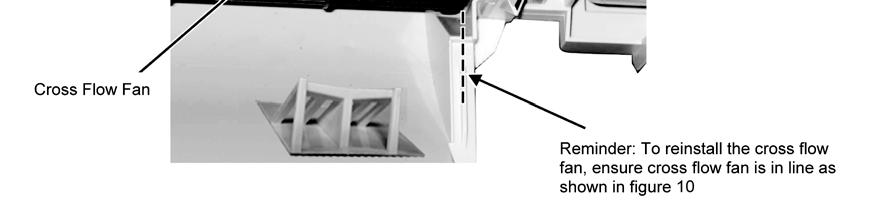
86 Figure 0 86


87 6.2 Outdoor Electronic Controller Removal Procedure 6.2. CU-RE8RKE Remove the 8 screws of the Top Panel. 4 Remove the Control Board. Fig. 2 Remove the 8 screws of the Front Panel. Fig. 4 5 Remove the 6 screws of the Electronic Controller. Fig. 2 3 Remove the Top Cover of the Electronic Controller. Fig. 5 Caution! When handling electronic controller, be careful of electrostatic discharge. Fig. 3 87


88 6.2.2 CU-RE24RKE Remove the 8 screws of the Top Panel. Fig. 4 5 Remove the 6 screws of the Electronic Controller. Fig. 2 Remove the 8 screws of the Front Panel. Fig. 5 Fig. 2 3 Remove the Top Cover of the Electronic Controller. Caution! When handling electronic controller, be careful of electrostatic discharge. Fig. 3 4 Remove the Control Board. 88
AUTO COOL DRY FAN SPEED AIR SWING OFF ON TIMER TIMER OFF/ON FAN SPEED MODE TEMP AIR SWING TIMER ON SET OFF CANCEL AC RC SET CHECK CLOCK RESET
 AUTO COOL DRY MODE TIMER ON OFF TIMER OFF/ON TEMP ON TIMER FAN SPEED AIR SWING SET 1 2 3 FAN SPEED AIR SWING OFF CANCEL AC RC SET CHECK CLOCK RESET Order No: PAPAMY1611008CE Indoor Unit CS-MPS9SKH CS-MPS12SKH
AUT O HE AT COOL DRY FAN SPEE D AIR SW ING OFF/ON MODE TEMP AIR SW ING POWERFUL/ QUIET TIMER ON SET OFF CANCEL SET CHECK CLOCK RESET WARNING
 AUT O HE AT COOL DRY POWERFUL/ QUIET FAN SPEE D AC AIR SW ING SET CHECK CLOCK RESET FAN SPEED AIR SW ING RC Order No: PAPAMY502046CE Indoor Unit CS-RE9RKEW CS-RE2RKEW CS-RE5RKEW Outdoor Unit CU-RE9RKE
CU-3E23CBPG, CU- 4E27CBPG,
 Order No. PHAAM0810051C2 Air Conditioner Indoor Unit Outdoor Unit CS-E7JKEW CU-E7JKE CS-E9JKEW CU-E9JKE CS-E12JKEW CU-E12JKE CS-E15JKEW CU-E15JKE CS-E15JKEW CU-E15JKE-1 CS-E7JKEW-3 CU-E7JKE-3 CS-E9JKEW-3
IMPORTANT SAFETY NOTICE
 Order No: PAPAMY703052CE Indoor Unit CS-TE20TKEW CS-TE25TKEW CS-TE35TKEW CS-TE42TKEW Outdoor Unit CU-TE20TKE CU-TE25TKE CU-TE35TKE CU-TE42TKE Destination Europe Turkey Please file and use this manual together
Destination Europe WARNING
 Order No: PAPAMY1406071CE Indoor Unit CS-E12QD3EAW Outdoor Unit CU-E12QD3EA Destination Europe Please file and use this manual together with the service manual for Model No. CU-2E15PBE CU-2E18PBE CU-3E18PBE
TABLE OF CONTENTS. Air Conditioner CS-MRE12MKE
 Order No. PHAAM1103074C8 Indoor Unit CS-MRE7MKE CS-MRE9MKE CS-MRE12MKE Air Conditioner Outdoor Unit CU-2RE15MBE CU-2RE18MBE TABLE OF CONTENTS PAGE 1 Safety Precautions-----------------------------------------------
CU-S9NKV-7 CU-S12NKV-7 CU-S18NKV-7 CU-S22NKV-7 CS-S9NKV-7 CS-S12NKV-7 CS-S18NKV-7 CS-S22NKV-7 WARNING
 Order No: PAPAMY1206010CE Indoor Unit CS-S9NKV-7 CS-S12NKV-7 CS-S18NKV-7 CS-S22NKV-7 Outdoor Unit CU-S9NKV-7 CU-S12NKV-7 CU-S18NKV-7 CU-S22NKV-7 WARNING This service information is designed for experienced
Air Conditioner CONTENTS CS-E18EKU CU-E18EKU CS-E21EKU CU-E21EKU. Order No: MAC C1
 Order No: MAC0512115C1 CS-E18EKU CU-E18EKU CS-E21EKU CU-E21EKU Air Conditioner CONTENTS Page Page 1 Safety Precautions 3 2 Specification 5 2.1. CS-E18EKU CU-E18EKU 5 2.2. CS-E21EKU CU-E21EKU 7 3 Location
TABLE OF CONTENTS. Air Conditioner. Indoor Unit Outdoor Unit CS-NE9LKE CU-NE9LKE CS-NE12LKE CU-NE12LKE CS-XE9LKE-5 CU-NE9LKE CS-XE12LKE-5 CU-NE12LKE
 Order No. PHAAM1007139C2 Air Conditioner Indoor Unit Outdoor Unit CS-NE9LKE CU-NE9LKE CS-NE12LKE CU-NE12LKE CS-XE9LKE-5 CU-NE9LKE CS-XE12LKE-5 CU-NE12LKE TABLE OF CONTENTS PAGE 1 Safety Precautions-----------------------------------------------
TABLE OF CONTENTS. Air Conditioner CS-E24GKES CU-E24GKE CS-E28GKE CU-E28GKE
 Order No. MAC0701008C2 CS-E24GKES CU-E24GKE CS-E28GKE CU-E28GKE Air Conditioner TABLE OF CONTENTS PAGE 1 Safety Precautions----------------------------------------------- 2 2 Specifications -----------------------------------------------------
TABLE OF CONTENTS. Air Conditioner CS-NE7GKE CU-NE7GKE CS-NE9GKE CU-NE9GKE CS-NE12GKE CU-NE12GKE
 Order No. MAC0705021C2 Air Conditioner CS-NE7GKE CU-NE7GKE CS-NE9GKE CU-NE9GKE CS-NE12GKE CU-NE12GKE TABLE OF CONTENTS PAGE 1 Safety Precaution ------------------------------------------------ 2 2 Specifications
Air-to-Water Heatpump
 Order No. PHAAM1006120C2 Air-to-Water Heatpump Indoor Unit Outdoor Unit WH-SDC07C3E5 WH-UD07CE5-A WH-SDC09C3E5 WH-UD09CE5-A WH-SDC12C6E5 WH-UD12CE5-A WH-SDC14C6E5 WH-UD14CE5-A WH-SDC16C6E5 WH-UD16CE5-A
CS-XE9EKE CU-XE9EKE CS-XE12EKE CU-XE12EKE
 Order No. MAC0512111C8 Air Conditioner CS-XE9EKE CU-XE9EKE CS-XE12EKE CU-XE12EKE TABLE OF CONTENTS PAGE 1 Safety Precautions----------------------------------------------- 3 2 Specifications -----------------------------------------------------
CS-E18NKUA CS-E24NKUA CU-E18NKUA CU-E24NKUA TABLE OF CONTENTS WARNING
 Order No: PAPAMY1204088CE Indoor Unit CS-E18NKUA CS-E24NKUA Outdoor Unit CU-E18NKUA CU-E24NKUA WARNING This service information is designed for experienced repair technicians only and is not designed for
CS-CZ9SKE CS-CZ12SKE CU-CZ9SKE CU-CZ12SKE. Destination N. Europe WARNING CAUTION
 POWER / DEICE TIMER HEAT Order No: PAPAMY1607084CE Indoor Unit CS-CZ9SKE CS-CZ12SKE Outdoor Unit CU-CZ9SKE CU-CZ12SKE Destination N. Europe WARNING This service information is designed for experienced
CU-HZ25TKE CU-HZ35TKE CU-HZ25TKE-5 CS-HZ25TKE CS-HZ35TKE CS-HZ25TKE-5. Destination North Europe
 Order No: PAPAMY1707099CE Indoor Unit CS-HZ25TKE CS-HZ35TKE CS-HZ25TKE-5 Outdoor Unit CU-HZ25TKE CU-HZ35TKE CU-HZ25TKE-5 Destination North Europe WARNING This service information is designed for experienced
Destination Europe Turkey
 OFF / ON Order No: PAPAMY1505102CE Indoor Unit CS-E18RD3EAW Outdoor Unit CU-E18RBEA Destination Europe Turkey WARNING This service information is designed for experienced repair technicians only and is
CU-YE9MKE CU-YE12MKE CU-YE18MKE CS-YE9MKE CS-YE12MKE CS-YE18MKE TABLE OF CONTENTS WARNING
 Order No: PHA-AG1102003C2 Indoor Unit CS-YE9MKE CS-YE12MKE CS-YE18MKE Outdoor Unit CU-YE9MKE CU-YE12MKE CU-YE18MKE WARNING This service information is designed for experienced repair technicians only and
TABLE OF CONTENTS. Air Conditioner
 Order No. MAC0804027A2 Air Conditioner CS-E9GFEW-2 CU-E9GFE-2 CS-E12GFEW-2 CU-E12GFE-2 CS-E18GFEW-2 CU-E18GFE-2 CU-2E15GBE CU-3E18EBE CU-3E23CBPG CU-4E27CBPG Please file and use this manual together with
WARNING IMPORTANT SAFETY NOTICE
 Order No: PAPAMY8020CE Indoor Unit CS-FZ25UKE CS-FZ35UKE CS-FZ50UKE CS-FZ60UKE Outdoor Unit CU-FZ25UKE CU-FZ35UKE CU-FZ50UKE CU-FZ60UKE Destination Europe Turkey FAN SPEED FAN SPEED WARNING This service
CS-RE9JKX-1 CS-RE12JKX-1 CS-RE15JKX-1 CU-RE9JKX-1 CU-RE12JKX-1 CU-RE15JKX-1 TABLE OF CONTENTS WARNING
 Order No: PHA-AG1002007C2 Indoor Unit CS-RE9JKX-1 CS-RE12JKX-1 CS-RE15JKX-1 Outdoor Unit CU-RE9JKX-1 CU-RE12JKX-1 CU-RE15JKX-1 WARNING This service information is designed for experienced repair technicians
CS-UE9PKE CS-UE12PKE CU-UE9PKE CU-UE12PKE TABLE OF CONTENTS WARNING
 Order No: PAPAGZ121215CE Indoor Unit CS-UE9PKE CS-UE12PKE Outdoor Unit CU-UE9PKE CU-UE12PKE WARNING This service information is designed for experienced repair technicians only and is not designed for
CU-Z7SKE CU-Z9SKE CU-Z12SKE CU-Z18SKE CS-XZ7SKEW CS-XZ9SKEW CS-XZ12SKEW CS-XZ18SKEW. Destination EU E.Europe L.America Turkey WARNING
 Order No: PAPAMY1604028CE Indoor Unit CS-XZ7SKEW CS-XZ9SKEW CS-XZ12SKEW CS-XZ18SKEW Outdoor Unit CU-Z7SKE CU-Z9SKE CU-Z12SKE CU-Z18SKE Destination EU E.Europe L.America Turkey WARNING This service information
Air-to-Water Hydromodule + Tank WH-UX12FE5 WH-UD12FE5 WH-UD16FE5. Destination Europe WARNING
 Order : PAPAMY420CE Air-to-Water Hydromodule + Tank Indoor Unit WH-ADC26G6E5 Outdoor Unit WH-UX09FE5 WH-UX2FE5 WH-UD2FE5 WH-UD6FE5 Destination Europe WARNING This service information is designed for experienced
DC INVERTER MULTI-SYSTEM AIR CONDITIONER
 TECHNICAL & SERVICE MANUAL OUTDOOR UNIT : CU-3KE19NBU CU-4KE24NBU CU-4KE31NBU DC INVERTER MULTI-SYSTEM AIR CONDITIONER Capacity at 0V 19,100 BTU/h,200 BTU/h 30,600 BTU/h Outdoor Model No. CU-3KE19NBU CU-4KE24NBU
INSTALLATION MANUAL. Split-type Air Conditioner (Cooling and Heating) Outdoor Unit UQB09JJWC UQB12JJWC. Indoor Unit AQB09JJWC AQB12JJWC
 Outdoor Unit UQB09JJWC UQB12JJWC. Indoor Unit AQB09JJWC AQB12JJWC") AQB09JJ6WC_IM_E_2585 2006.4.17 4:26 PM Page 17 INSTALLATION MANUAL Indoor Unit AQB09JJWC AQB12JJWC Outdoor Unit UQB09JJWC UQB12JJWC ENGLISH FRANÇAIS ESPAÑOL Split-type Air Conditioner (Cooling and Heating)
AQB09JJ6WC_IM_E_2585 2006.4.17 4:26 PM Page 17 INSTALLATION MANUAL Indoor Unit AQB09JJWC AQB12JJWC Outdoor Unit UQB09JJWC UQB12JJWC ENGLISH FRANÇAIS ESPAÑOL Split-type Air Conditioner (Cooling and Heating)
INSTALLATION MANUAL. Split-type Air Conditioner (Cooling and Heating) Indoor Unit AQB18J6WC AQB24J2WC. Outdoor Unit UQB18J6WC UQB24J2WC
 Indoor Unit AQB18J6WC AQB24J2WC. Outdoor Unit UQB18J6WC UQB24J2WC") AQB8J6WC_IM_E_25864 2006.4.4 3:29 PM Page 7 INSTALLATION MANUAL Indoor Unit AQB8J6WC AQB24J2WC Outdoor Unit UQB8J6WC UQB24J2WC ENGLISH FRANÇAIS ESPAÑOL Split-type Air Conditioner (Cooling and Heating)
AQB8J6WC_IM_E_25864 2006.4.4 3:29 PM Page 7 INSTALLATION MANUAL Indoor Unit AQB8J6WC AQB24J2WC Outdoor Unit UQB8J6WC UQB24J2WC ENGLISH FRANÇAIS ESPAÑOL Split-type Air Conditioner (Cooling and Heating)
Split-type Air-Conditioner INSTALLATION MANUAL CONTENTS FOR INSTALLER MXZ-3B54VA MXZ-4B71VA. English
 Split-type Air-Conditioner MXZ-3B54VA MXZ-4B71VA INSTALLATION MANUAL English Refer to the installation manual of each indoor unit for indoor unit installation. IMPORTANT NOTES TO COMPLY WITH THE REQUIREMENTS
Air Conditioner CONTENTS CS-TE9DKE CU-TE9DKE CS-TE12DKE CU-TE12DKE. Order No. RAC C2
 Order No. RAC0502005C2 Air Conditioner CS-TE9DKE CU-TE9DKE CS-TE12DKE CU-TE12DKE CONTENTS Page Page 1 Features 2 2 Functions 3 2.1. Remote Control 3 2.2. Indoor Unit 4 2.3. Outdoor unit 5 3 Product Specifications
INSTALLATION MANUAL COMFORT...BUILT TO LAST. 9,000, 12,000 and 18,000 BTU SINGLE-ZONE DUCTLESS MINI-SPLIT SYSTEM Heat Pump
 COMFORT...BUILT TO LAST 9,000, 12,000 and 18,000 BTU SINGLE-ZONE DUCTLESS MINI-SPLIT SYSTEM Heat Pump INSTALLATION MANUAL INDOOR UNIT: 1PAMSH09-SZW-14.5 1PAMSH09-SZW-15 1PAMSH12-SZW-15 1PAMSH18-SZW-15
Room Air Conditioner CONTENTS CS-E9BKP CU-E9BKP5 CS-E12BKP CU-E12BKP5. Order No: MAC C2
 Order No: MAC008C Room Air Conditioner CS-E9BKP CU-E9BKP5 CS-EBKP CU-EBKP5 CONTENTS Page Page Features Functions Product Specifications 6 Dimensions 0 5 Refrigeration Cycle Diagram 6 Block Diagram 7 Wiring
DC INVERTER MULTI-SYSTEM AIR CONDITIONER
 TECHNICAL & SERVICE MANUAL OUTDOOR UNIT : CLM97 CLM7 CLM7 FILE NO. Destination: North America DC INVERTER MULTI-SYSTEM AIR CONDITIONER Capacity at 0V 9,700 BTU/h,00 BTU/h 0,600 BTU/h Outdoor Model No.
TECHNICAL DATA & SERVICE MANUAL
 TECHNICAL DATA & SERVICE MANUAL OUTDOOR UNIT: GRF188R5TAA GRF228R5TAA GRF228R7TAA SPLIT SYSTEM AIR CONDITIONER Model No. Product Code No. GRF188R5TAA 38.7107.083 GRF228R5TAA 38.7107.084 GRF228R7TAA 38.7107.085
Split-type Air-Conditioner
 Split-type Air-Conditioner MXZ-2C52VA Installation Manual For INSTALLER This manual only describes the installation of outdoor unit. When installing the indoor unit, refer to the installation manual of
Split-type Air-Conditioner
 Split-type Air-Conditioner MXZ-2D52VA Installation Manual For INSTALLER This manual only describes the installation of outdoor unit. When installing the indoor unit, refer to the installation manual of
TECHNICAL DATA & SERVICE MANUAL
 TECHNICAL DATA & SERVICE MANUAL OUTDOOR UNIT:. TRIAL SPLIT SYSTEM AIR CONDITIONER Model No. Product Code No. 38.7107.102. 0.8180.611.02 09/2012 IMPORTANT! Please read before installation This air conditioning
Air Conditioner. Outdoor Unit CU-2Z35TBE CU-2Z41TBE CU-2Z50TBE. Destination Europe
 Order No: PAPAMY1702035CE Air Conditioner Outdoor Unit CU-2Z35TBE CU-2Z41TBE CU-2Z50TBE Destination Europe Please file and use this manual together with the service manual for Model No. CS-MZ16TKE CS-Z20TKEW
AOYG18LFC OUTDOOR UNIT INSTALLATION MANUAL INSTALLATION MANUAL. For authorized service personnel only. PART NO
 AOYG8LFC OUTDOOR UNIT INSTALLATION MANUAL INSTALLATION MANUAL For authorized service personnel only. English PART NO. 93778639 93778639_IM.indb /20/20 6:07:25 PM AIR CONDITIONER OUTDOOR UNIT INSTALLATION
SINGLE - ZONE Ductless Split System Heat Pumps Installation, Operation & Maintenance Manual
 Presents SINGLE - ZONE Ductless Split System Heat Pumps Installation, Operation & Maintenance Manual 9k,12k 18k 24k, 30k, 36k ECR International, Inc. 2201 Dwyer Avenue, Utica NY 13501 Phone: 800.325.5479
DC INVERTER SPLIT SYSTEM AIR CONDITIONER
 AIR CONDITIONER TECHNICAL & SERVICE MANUAL KS1872 + C1872 + CL1872 KS2472 + C2472 + CL2472 FILE NO. Destination: North America DC INVERTER SPLIT SYSTEM AIR CONDITIONER Indoor Model No. KS1872 KS2472 Product
Installation and Operation Manual. CMA12SB-0 Series. Horizontal/Side Discharge Condensing Units
 Installation and Operation Manual CMA12SB-0 Series Horizontal/Side Discharge Condensing Units 517.787.2100 www.marsdelivers.com www.heatcontroller.com Heat Controller CONTENTS PAGE 1. PRES... 1 2. INSTALLATION
Air Conditioner CONTENTS CS-V18DKE CU-V18DKE CS-V24DKE CU-V24DKE. Order No. MAC C2
 Order No. MAC0410044C2 CS-V18DKE CU-V18DKE CS-V24DKE CU-V24DKE Air Conditioner CONTENTS Page Page 1 Features 2 2 Functions 3 2.1. Remote Control 3 2.2. Indoor Unit 4 2.3. Outdoor Unit 5 3 Product Specifications
1. BEFORE INSTALLATION
 ENGLISH SPLIT-TYPE AIR CONDITIONERS INSTALLATION MANUAL MSZ-D30/36NA MSY-D30/36NA JG79A061H09 Phillips screwdriver Level Scale Utility knife or scissors 3 in. (75 mm) hole saw Torque wrench Wrench (or
Installation Instructions
 40MAQ High Wall Ductless Split System Sizes 09 to 36 Installation Instructions NOTE: Read the entire instruction manual before starting the installation TABLE OF CONTENTS PAGE SAFETY CONSIDERATIONS 2 PARTS
TECHNICAL DATA & SERVICE MANUAL
 TECHNICAL DATA & SERVICE MANUAL INDOOR UNIT: CAF97R5IAA CAF98MR5IAA CAF127R5IAA CAF128MR5IAA CAF187R5IAA SPLIT SYSTEM AIR CONDITIONER Model No. CAF97R5IAA CAF127R5IAA CAF187R5IAA CAF98MR5IAA CAF128MR5IAA
SPLIT-TYPE ROOM AIR CONDITIONER
 Before using your air conditioner, please read this manual carefully and keep it for future reference SPLIT-TYPE ROOM AIR CONDITIONER Please read this installation manual completely before installing the
DAIKIN AIR CONDITIONER
 3P226011-1A M07B242A DAIKIN AIR CONDITIONER Two-dimensional bar code is a code for manufacturing. Safety Precautions (1) Read these Safety Precautions carefully to ensure correct installation. This manual
1. BEFORE INSTALLATION
 ENGLISH SPLIT-TYPE AIR CONDITIONERS INSTALLATION MANUAL MSZ-D30/36NA MSY-D30/36NA JG79A061H01 Phillips screwdriver Level Scale Utility knife or scissors 3 in. (75 mm) hole saw Torque wrench Wrench (or
Air-to-Water Hydromodule + Tank WH-UD05HE5-1 WH-UD07HE5-1 WH-UD09HE5-1. Destination Europe Turkey
 Order : PAPAMY1607068CE Air-to-Water Hydromodule + Tank Indoor Unit WH-ADC0309H3E5 Outdoor Unit WH-UD03HE5-1 WH-UD05HE5-1 WH-UD07HE5-1 WH-UD09HE5-1 Destination Europe Turkey WARNING This service information
TECHNICAL DATA & SERVICE MANUAL
 TECHNICAL DATA & SERVICE MANUAL OUTDOOR UNIT: AE726SCL AE752SCL AE71SCL3 AE735SCL AE752SCL3 AE100SCL3 AE764SCL3 AE125SCL3 SPLIT SYSTEM AIR CONDITIONER Model No. AE726SCL AE735SCL AE752SCL AE752SCL3 AE764SCL3
1. BEFORE INSTALLATION
 ENGLISH SPLIT-TYPE AIR CONDITIONERS INSTALLATION MANUAL JG79A191H07 MSZ-GE06/09/12/15/18NA MSY-GE09/12/15/18NA When installing multi units, refer to the installation manual of the multi unit for outdoor
1. BEFORE INSTALLATION
 ENGLISH SPLIT-TYPE AIR CONDITIONERS INSTALLATION MANUAL MSZ-FH09/12/15NA JG79A805H01 When installing multi units, refer to the installation manual of the multi unit for outdoor unit installation. Phillips
INSTALLATION INSTRUCTIONS
 INSTALLATION INSTRUCTIONS Solenoid Valve Kit For 3WAY VRF System CZ-PXXXHR3 () IMPORTANT! Please Read Before Starting This solenoid Valve kit must be installed by the sales dealer or installer. This information
CONTENTS INSTALLATION MANUAL HFC FOR INSTALLER R410A. utilized 1. THE FOLLOWING SHOULD ALWAYS BE OBSERVED FOR SAFETY... 2
 SPLIT-TYPE AIR CONDITIONER CONTENTS INSTALLATION MANUAL 1. THE FOLLOWING SHOULD ALWAYS BE OBSERVED FOR SAFETY... 2 Model MXZ-A26/32WV HFC utilized R410A 2. INSTALLATION DIAGRAM & ACCESSORIES... 2 3. SELECTING
TECHNICAL & SERVICE MANUAL WINDOW TYPE AIR CONDITIONER SA 183A FILE NO. SA 183A REFERENCE NO. SM Destination Australia SA-183A
 TECHNICAL & SERVICE MANUAL SA 183A FILE NO. WINDOW TYPE AIR CONDITIONER Model No. Product Code No. SA-183A 1 851 006 96 Destination Australia SA 183A REFERENCE NO. SM700514 IMPORTANT! Please Read Before
[FLARE CONNECTION TYPE] ATTENTION
![[FLARE CONNECTION TYPE] ATTENTION](/thumbs/88/117511702.jpg "[FLARE CONNECTION TYPE] ATTENTION") SPLIT-TYPE AIR CONDITIONERS Model MXZ-2A20NA [FLARE CONNECTION TYPE] HFC utilized R410A INSTALLATION MANUAL ATTENTION This manual mentions how to install only the outdoor unit, MXZ-2A20NA. As for the way
SPLIT-TYPE AIR CONDITIONERS Model MXZ-2A20NA [FLARE CONNECTION TYPE] HFC utilized R410A INSTALLATION MANUAL ATTENTION This manual mentions how to install only the outdoor unit, MXZ-2A20NA. As for the way
TECHNICAL & SERVICE MANUAL WINDOW TYPE AIR CONDITIONER SA 128S5 FILE NO. SA 128S5 REFERENCE NO. SM700338
 TECHNICAL & SERVICE MANUAL SA 128S5 FILE NO. WINDOW TYPE AIR CONDITIONER Model No. Product Code No. Destination SA-128S5-A 1 851 004 09 General (50Hz) & Europe SA 128S5 REFERENCE NO. SM700338 IMPORTANT!
Installation Instructions
 40MBFQ Floor Console Ductless System Sizes 09 to 58 Installation Instructions TABLE OF CONTENTS PAGE SAFETY CONSIDERATIONS... 2 PARTS LIST... 3 SYSTEM REQUIREMENTS... 4 WIRING... 4 DIMENSIONS... 5 CLEARANCES...
R32 INSTALLATION MANUAL ENGLISH AIR CONDITIONER (SPLIT TYPE) Indoor unit RAS-10PKVPG-E RAS-13PKVPG-E RAS-16PKVPG-E
 Indoor unit RAS-10PKVPG-E RAS-13PKVPG-E RAS-16PKVPG-E") R32 INSTALLATION MANUAL AIR CONDITIONER (SPLIT TYPE) ENGLISH Indoor unit RAS-10PKVPG-E RAS-13PKVPG-E RAS-16PKVPG-E Outdoor unit RAS-10PAVPG-E RAS-13PAVPG-E RAS-16PAVPG-E 1121451198 EN CONTENTS PRES FOR
R32 INSTALLATION MANUAL AIR CONDITIONER (SPLIT TYPE) ENGLISH Indoor unit RAS-10PKVPG-E RAS-13PKVPG-E RAS-16PKVPG-E Outdoor unit RAS-10PAVPG-E RAS-13PAVPG-E RAS-16PAVPG-E 1121451198 EN CONTENTS PRES FOR
HEAT PUMP INSTALLATION MANUAL
 DUCTLESS INVERTER HEAT PUMP INSTALLATION MANUAL Models: TERRA09HP230V1A TERRA12HP230V1A TERRA18HP230V1B TERRA24HP230V1B Thank you for choosing a Gree Terra Ductless Heat Pump for your customer. Please
Operating Instructions
 Operating Instructions Air Conditioner Model No. Indoor Unit CS-PC9QKH CS-PC12QKH CS-PC18QKH CS-PC24QKH CS-PC28QKH Outdoor Unit CU-PC9QKH CU-PC12QKH CU-PC18QKH CU-PC24QKH CU-PC28QKH Operating Instructions
ROOM AIR CONDITIONER INSTALLATION MANUAL
 ROOM AIR CONDITIONER INSTALLATION MANUAL (Inverter Split Type) Please read this installation manual completely before installing the product When the power cord is damaged, replacement work shall be performed
MXZ-4B80VA MXZ-5B100VA INSTALLATION MANUAL
 Split-type Air-Conditioner MXZ-4B80VA MXZ-5B100VA INSTALLATION MANUAL Refer to the installation manual of each indoor unit for indoor unit installation. English Deutsch Français Nederlands Español Italiano
INSTALLATION MANUAL SPLIT TYPE ROOM AIR CONDITIONER (PART NO )
") SPLIT TYPE ROOM AIR CONDITIONER INSTALLATION MANUAL (PART NO. 9312791019-01) This air conditioner uses new refrigerant HFC (R410A). The basic installation work procedures are the same as conventional refrigerant
SPLIT TYPE ROOM AIR CONDITIONER INSTALLATION MANUAL (PART NO. 9312791019-01) This air conditioner uses new refrigerant HFC (R410A). The basic installation work procedures are the same as conventional refrigerant
WH-UD03HE5 WH-UD05HE5 WH-SDC03H3E5 WH-SDC05H3E5. Destination Europe Turkey WARNING
 Order No: PAPAMY1509111CE Indoor Unit WH-SDC03H3E5 WH-SDC05H3E5 Outdoor Unit WH-UD03HE5 WH-UD05HE5 Destination Europe Turkey WARNING This service information is designed for experienced repair technicians
INSTALLATION MANUAL. R410A Split Series. Model RXS24LVJU. Installation manual R410A Split series. Manual de instalación Serie Split R410A.
 INSTALLATION MANUAL R410A Split Series Installation manual R410A Split series English Français Manual de instalación Serie Split R410A Español Model RXS24LVJU Safety Precautions Read these Safety Precautions
Safety Precautions (1)
") 3P207257-3D M07B061D DAIKIN AIR CONDITIONER Two-dimensional bar code is a code for manufacturing. Safety Precautions (1) Read these Safety Precautions carefully to ensure correct installation. This manual
3P207257-3D M07B061D DAIKIN AIR CONDITIONER Two-dimensional bar code is a code for manufacturing. Safety Precautions (1) Read these Safety Precautions carefully to ensure correct installation. This manual
Choosing the installation site. Installation. 07 Choosing the installation site
 Installation Installation warnings: 1. Carefully read the installation manual before beginning. 2. Follow each step as shown. 3. Observe all local, state, and national electrical codes and by qualified,
WH-TD20B3E5 WH-TD30B3E5
 Order No: PHAAM1004143C2 WH-TD20B3E5 WH-TD30B3E5 WARNING This service information is designed for experienced repair technicians only and is not designed for use by the general public. It does not contain
Split-type Air-Conditioner
 Split-type Air-Conditioner MXZ-2E52VAD MXZ-3E54VAD MXZ-4E71VAD Installation Manual For INSTALLER This manual only describes the installation of outdoor unit. When installing the indoor unit, refer to the
INVERTER SPLIT - TYPE
 INVERTER SPLIT - TYPE ISSUE No 2 DATE 04/09/08 P/No 2020323A2868 CONTENTS SAFETY PRECAUTIONS Warning 2 Operating temperature 2 BEFORE INSTALLATION Tools needed for installation 3 Items required for installing
TECHNICAL & SERVICE MANUAL WINDOW TYPE AIR CONDITIONER SA 123A FILE NO. SA 123A REFERENCE NO. SM700513
 TECHNICAL & SERVICE MANUAL SA 123A FILE NO. WINDOW TYPE AIR CONDITIONER Model No. Product Code No. Destination SA-123A 1 851 006 95 Australia SA 123A REFERENCE NO. SM700513 IMPORTANT! Please Read Before
Installation Instructions
 38MHR Outdoor Unit Single Zone Ductless System Sizes 09 to 24 Installation Instructions NOTE: Read the entire instruction manual before starting the installation. NOTE: Images are for illustration purposes
INSTALLATION MANUAL Duct Type Series MH FECA
 INSTALLATION MANUAL Duct Type Series MH FECA ENGLISH FRANÇAIS ESPAÑOL Free Joint Multi Air Conditioner (Cooling and Heating) E S F DB98-960A() Safety Precautions The following safety precautions must be
Installation Instructions
 40MHH High Wall Ductless System Sizes 09 to 24 Installation Instructions NOTE: Read the entire instruction manual before starting the installation. NOTE: Images are for illustration purposes only. Actual
Installation Instructions
 40MBFQ Floor Console Ductless System Sizes 09 to 12 Installation Instructions TABLE OF CONTENTS PAGE SAFETY CONSIDERATIONS... 2 PARTS LIST... 3 SYSTEM REQUIREMENTS... 4 DIMENSIONS... 5 CLEARANCES... 5
Installation Manual. KS Series KS09 KS12 KS18 KS24 KS28. J3387_Kaden_Installer_Manual_ indd 1
 Wall Mounted AIR CONDITIONER Installation Manual KS Series KS09 KS12 KS18 KS24 KS28 J3387_Kaden_Installer_Manual_050917.indd 1 5/09/2017 9:07 AM J3387_Kaden_Installer_Manual_050917.indd 2 5/09/2017 9:07
1. BEFORE INSTALLATION
 ENGLISH SPLIT-TYPE AIR CONDITIONERS INSTALLATION MANUAL Model names are indicated in 1-3. JG79A145H05 Phillips screwdriver Level Scale Utility knife or scissors 75 mm hole saw Torque wrench Wrench (or
TECHNICAL DATA & SERVICE MANUAL SPLIT SYSTEM AIR CONDITIONER INDOOR UNIT: AW22AL AW28AL AW38AL AW42AL AW22AL AW28AL AW38AL
 TECHNICAL DATA & SERVICE MANUAL INDOOR UNIT: AW22AL AW28AL AW38AL AW42AL SPLIT SYSTEM AIR CONDITIONER Model No. Product Code No. AW22AL 387030005 AW28AL 387030006 AW38AL 387030007 AW42AL 387030094 0.8180.467.0
DC INVERTER SPLIT SYSTEM AIR CONDITIONER
 TECHNICAL & SERVICE MANUAL XHS1271 & PNR-XS1872 + CH1271 XHS1872 & PNR-XS1872 + CH1872 FILE NO. Destination: North America DC INVERTER SPLIT SYSTEM AIR CONDITIONER Indoor Model No. Body (Panel) XHS1271
TECHNICAL DATA & SERVICE MANUAL
 TECHNICAL DATA & SERVICE MANUAL OUTDOOR UNIT: DUAL SPLIT SYSTEM AIR CONDITIONER Model No. Product Code No. 38.7107.098 38.7107.103 38.7107.106 0.8180.597.03 09/2012 IMPORTANT! Please read before installation
TECHNICAL DATA & SERVICE MANUAL SPLIT SYSTEM AIR CONDITIONER OUTDOOR UNIT: AE22AC/ACL/AH AE28AC/ACL/AH AE38AC/ACL/AH AE42AC/ACL/AH
 TECHNICAL DATA & SERVICE MANUAL OUTDOOR UNIT: AE22AC/ACL/AH AE28AC/ACL/AH AE38AC/ACL/AH AE42AC/ACL/AH SPLIT SYSTEM AIR CONDITIONER Model No. Product Code No. AE22AH 387031006 AE28AH 387031007 AE38AH 387031008
TABLE OF CONTENTS. NOTE: Read the entire instruction manual before starting the installation. TROUBLESHOOTING... 13
 R 410A Duct Free Split System Air Conditioner and Heat Pump Product Family: DFS4(A/H) System, DFC4(A/H)3 Outdoor, DFF4(A/H)H Indoor NOTE: Read the entire instruction manual before starting the installation.
Room Air Conditioner Service and Parts Manual
 Cool Dry Temp Mode Room Air Conditioner Service and Parts Manual F Fan Speed hr Timer 0n 0ff Money Saver Fan Only Auto Swing Power CP06 CP08 93011401_01 CONTENTS 1. PREFACE 1.1 SAFETY PRECAUTIONS...2 1.2
DC INVERTER SPLIT SYSTEM AIR CONDITIONER
 TECHNICAL & SERVICE MANUAL XS171 & PNRXS187 + C171 XS171 & PNRXS187 + CL171 XS187 & PNRXS187 + CH187 XS187 & PNRXS187 + CL187 FILE NO. Destination: North America DC INVERTER SPLIT SYSTEM AIR CONDITIONER
Operating Instructions Air Conditioner
 alleru-buster F566894 Operating Instructions Air Conditioner Indoor Unit CS-RE9JKR CS-RE1JKR Outdoor Unit CU-RE9JKR CU-RE1JKR ENGLISH ~ 7 Before operating the unit, read these operating instructions thoroughly
INSTALLATION MANUAL. R410A Split Series. Models RXS15LVJU RXS18LVJU. Installation manual R410A Split series. Manuel dinstallation Série split R410A
 INSTALLATION MANUAL R410A Split Series Installation manual R410A Split series English Manuel dinstallation Série split R410A Français Manual de instalación Serie Split R410A Español Models RXS15LVJU RXS18LVJU
INSTALLATION MANUAL. R22 Split Series. Models FTY25GXV1 FTY35GXV1. Installation manual R22 Split series
 00_CV_3P211822-2C.fm Page 1 Tuesday, November 27, 2007 6:24 PM INSTALLATION MANUAL R22 Split Series Installation manual R22 Split series English Рóêоводство по монтажó Серия R22 с раздельной óстановêой
1. BEFORE INSTALLATION
 ENGLISH SPLIT-TYPE AIR CONDITIONERS INSTALLATION MANUAL REFRIGERANT JG79B528H01 Model names are indicated in 1-3. Phillips screwdriver Level Scale Utility knife or scissors 75 mm hole saw Torque wrench
Operating Instructions Air Conditioner
 F56690 Operating Instructions Air Conditioner Indoor Unit CS-S9JKR CS-S1JKR Outdoor Unit CU-S9JKR CU-S1JKR Before operating the unit, read these operating instructions thoroughly and keep them for future
Installation Instructions
 8GXM / 0GXM Multi---Split High---Wall Duct Free Split System 8GXM --- Size 18k, k, and 0k 0GXM --- Size 9k, 1k, and 18k Installation Instructions NOTE: Read the entire instruction manual before starting
1. BEFORE INSTALLATION
 ENGLISH SPLIT-TYPE AIR CONDITIONERS INSTALLATION MANUAL REFRIGERANT JG79B530H01 Model names are indicated in 1-3. Phillips screwdriver Level Scale Utility knife or scissors 75 mm hole saw Torque wrench
DLCLRA. INSTALLATION INSTRUCTIONS Outdoor Unit Single Zone Ductless System Sizes 36 to 58 TABLE OF CONTENTS
 DLCLRA INSTALLATION INSTRUCTIONS Outdoor Unit Single Zone Ductless System Sizes 36 to 58 Fig. 1 - Size 36 TABLE OF CONTENTS PAGE SAFETY CONSIDERATIONS... 2 PARTS LIST... 3 SYSTEM REQUIREMENTS... 4 WIRING...
FLOOR-STANDING SPLIT TYPE ROOM AIR CONDITIONER
 Before using your air conditioner, please read this manual carefully and keep it for future reference. FLOOR-STANDING SPLIT TYPE ROOM AIR CONDITIONER Please read this installation manual completely before
FLOOR-STANDING TYPE AIR CONDITIONER INSTALLATION MANUAL
 FLOOR-STANDING TYPE AIR CONDITIONER INSTALLATION MANUAL CONTENTS SAFETY PRECAUTIONS Warning... Caution... INSTALLATION INSTRUCTIONS Accessories...;...3 Selecting installation place...4 PIPE CONNECTION
Installation Instructions
 40MAQ High Wall Ductless System Sizes 09 to 36 Installation Instructions NOTES: Read the entire instruction manual before starting the installation. Images are for illustration purposes only. Actual models
DC INVERTER SPLIT SYSTEM AIR CONDITIONER
 AIR CONDITIONER TECHNICAL & SERVICE MANUAL CS-KE30NKU + CU-KE30NKU CS-KE36NKU + CU-KE36NKU DC INVERTER SPLIT SYSTEM AIR CONDITIONER Indoor Model No. CS-KE30NKU CS-KE36NKU Product Code No. 1 852 360 88
OWNER S AND INSTALLATION MANUAL RAV-480FS2B/RAV-480AS2B RAV-600FS8B/RAV-600AS8B
 OWNER S AND INSTALLATION MANUAL RAV-480FS2B/RAV-480AS2B RAV-600FS8B/RAV-600AS8B P/N: 52FS2B54070-R CONTENTS PRECAUTIONS Important Safety Information Hints For Economical Operation Standard Safety Instructions
Horizontal/Side Discharge Condensing Units
 INSTALLATION, OPERATION & MAINTENANCE MANUAL Horizontal/Side Discharge Condensing Units Models CMA12SD-0 CMA18SD-1 CMA24SD-1 CMA30SD-1 CMA36SD-1 CMA48SD-1 517.787.2100 www.marsdelivers.com Horizontal/Side
Operating Instructions
 Operating Instructions Air Conditioner Model No. Indoor Unit CS-E12QD3RW CS-E18QD3RW Single Split Outdoor Unit CU-E12QD3R CU-E18QD3R Multi Split Outdoor Unit CU-4E23QBR CU-4E27QBR CU-5E34QBR Operating