RSMSD Technical Guide
|
|
|
- Polly Chapman
- 5 years ago
- Views:
Transcription

1 RSMSD Technical Guide
2 AAON/WattMaster Controls Inc NW River Park Drive Parkville, MO Toll Free Phone: PH: (816) FAX: (816) Visit our web site at Copeland Digital Scroll is a registered trademark of Copeland Corporation, Sidney, OH WattMaster Form: AA-RSMSD-TGD-01C Copyright April 2018 WattMaster Controls, Inc. AAON Part Number: V97750 AAON is a registered trademark of AAON, Inc., Tulsa, OK. Neither WattMaster Controls, Inc. nor AAON assumes any responsibility for errors or omissions in this document. This document is subject to change without notice.
3 TABLE OF CONTENTS OVERVIEW... 4 Features and Applications... 4 Module Dimensions... 5 INSTALLATION & WIRING... 6 Input Wiring... 6 Suction Pressure Sensor... 6 Head Pressure Sensor... 6 Compressor Discharge Temperature Sensor... 6 Output Wiring... 7 Modulating Compressor... 7 Condenser Fan Signal... 7 INPUTS & OUTPUTS... 8 SEQUENCE OF OPERATIONS Cooling Mode Dehumidifi cation Operation Head Pressure Control TROUBLESHOOTING LED Diagnostics OE Suction Pressure Transducer Testing for R410A Copeland Discharge Thermistor Temperature Sensor Testing Leaving Water Temperature Sensor Testing Head Pressure Transducer Troubleshooting APPENDIX: CONDENSER CONFIGURATION One Condenser Per RSMSD On/Off Condenser Options
4 OVERVIEW RSMSD Overview Features & Applications The OE RSMSD Refrigerant System Module for Digital Compressors (RSMSD) (AAON Part No: V92410) monitors and controls the refrigeration circuit of a single digital compressor. The module is designed for R410-A refrigerant. The RSMSD is connected to the VCC-X / VCCX2 Controller. Only 1 RSMSD Module can be connected to the system. There are 2 E-BUS Expansion Ports which allow the use of communicating sensors and the E-BUS Modules. The RSMSD provides 2 analog inputs, 3 binary inputs, 3 relays, and 1 analog output. See Figures 2 & 3, pages 6 & 7 for wiring. The RSMSD Module provides the following: Modulates the Compressor to satisfy the Suction Coil (Saturated) Temperature. The Suction Coil (Saturated) Temperature Setpoint is reset by the VCC-X / VCCX2 Controller to maintain the Supply Air Temperature during Cooling Mode. During Dehumidification Mode, it controls the Compressor to the Suction (Saturation) Temperature Setpoint. In Heating mode, the RSMSD modulates and stages the compressor to maintain a given Supply Air Temperature Setpoint. Modulates the Condenser Fan or Valve to maintain the Head Pressure Setpoint. Provides alarms and safeties for the Compressor and Condenser operation. Allows connection of the Modular Service Tool SD to the module when required communication wire is run to the VCC-X / VCCX2 Controller. 4
5 OVERVIEW RSMSD Dimensions Figure 1: RSMSD Dimensions 5
6 WIRING RSMSD Inputs Wiring RSMSD Wiring The RSMSD monitors and controls the refrigeration circuit of a single digital compressor. The module is designed for R410-A refrigerant. The RSMSD is connected to the VCC-X / VCCX2 Controller. Only 1 RSMSD Module can be connected to the system. There are 2 E-BUS Expansion Ports which allow the use of communicating sensors and the E-BUS Modules. The RSMSD provides 2 analog inputs, 3 binary inputs, 3 relays, and 1 analog output. See Figure 2, below for inputs wiring and Figure 3, page 7 for outputs wiring. Suction Pressure Sensor Wiring The OE Suction Pressure Transducer must be wired as shown in Figure 2, below. It is typically required for all VCC-X / VCCX2 applications. The Suction Pressure Sensor is used to measure suction pressure at the HVAC unit s DX evaporator coil suction line. This suction line pressure is converted to saturated refrigerant temperature. The saturated refrigerant temperature is used to properly control the compressors to maintain a given Suction Coil (Saturated) Temperature Setpoint. In Cooling mode, the VCC-X / VCCX2 resets the Suction Coil (Saturated) Temperature Setpoint to maintain a given supply air temperature setpoint. In Dehumidification mode, the Suction Coil (Saturated) Temperature Setpoint is a user configurable setpoint that can be reset based on indoor humidity levels. OE RSMSD RSM FOR SINGLE DIGITAL COMPRESSOR SUCTION PRESSURE 1 SENSOR HEAD PRESSURE 1 SENSOR (BY OTHERS) RD WH BK RD WH BK +V SP +V HP COMP STATUS 1 BIN1 COMP. DISCHARGE TEMP. 1 SENSOR OUTSIDE COIL TEMP/POWF EMERGENCY SHUTDOWN BIN3 BIN4 TEMP 1 LEAVING WATER TEMP SENSOR TEMP 3 24VAC Size Transformer For Correct Total Load. RSMSD = 18 VA Line Voltage Figure 2: RSMSD Inputs Wiring 6
7 WIRING RSMSD Outputs Wiring CAUTION: The Shraeder port used for installation of the suction pressure transducer should be located in a vertical position of the suction line to prevent refrigerant oil from accumulating in the sensor. Compressor Discharge Sensor The Digital Compressor Discharge Temperature Sensor monitors the discharge temperature from the Digital Compressor to protect against overheating. Head Pressure Control The Head Pressure Transducer is used to measure Head Pressure at the discharge line. This Head Pressure is used to drive the Condenser Fan with a 0-10 VDC output signal or valve with a 2-10 VDC output signal to maintain a given Head Pressure Setpoint. Leaving Water Temperature Sensor The Leaving Water Temperature Sensor is used to measure the Leaving Water Temperature when used on a WSHP unit. OE RSMSD RSM FOR SINGLE DIGITAL COMPRESSOR NOTE: ALL RELAY OUTPUTS ARE NORMALLY OPEN AND RATED FOR 24 VAC POWER ONLY - 1 AMP MAXIMUM LOAD RLY1 RLY3 RLY5 COMM UNLOAD 24 VAC 24 VAC ONLY COMPRESSOR 1 ENABLE CONDENSER 1 ENABLE REVERSING VALVE + DIGITAL COMPRESSOR 1 AOUT1 CONDENSER SIGNAL 1 + COM Connects To VCC-X or VCCX2 Loop Communications Connector When Used On A Split System. Connect to VCC-X or VCCX2 Controller Line Voltage 24VAC Size Transformer For Correct Total Load. RSMSD = 18 VA Figure 3: RSMSD Outputs Wiring 7
8 INPUTS & OUTPUTS RSMSD Input/Output Map Zone Zone REFRIGERATION SYSTEM MODULE FOR DIGITAL COMPRESSORS Analog Inputs 1 Suction Pressure 1 Sensor (SP-1) 2 Head Pressure 1 Sensor (HP-1) 3 Not Used 4 Not Used Compressor Discharge Temperature Sensor 1 5 (TEMP1) 6 Not Used 7 Leaving Water Temperature Sensor (TEMP3) Binary Inputs 1 Compressor Status 1 (BIN1) 2 Not Used Outside Coil Temperature / Proof of Water Flow 3 (BIN3) 4 Emergency Shutdown (BIN4) Analog Outputs (0-10 VDC) 1 Condenser 1 Fan Signal (AOUT1) 2 Not Used Binary Outputs (24 VAC) 1 Compressor 1 Enable Relay (RLY1) 2 Not Used 3 Condenser 1 Enable Relay (RLY3) 4 Not Used 5 Reversing Valve Relay (RLY5) Table 1: RSMSD Inputs & Outputs 8
9 INPUTS & OUTPUTS RSMSD Inputs & Outputs RSMSD - Inputs & Outputs +5V VDC Power This output is a 5 VDC output that supplies power to the Suction Pressure Transducers. SP-1 - Suction Pressure Transducer The Suction Pressure Sensor is used to measure suction pressure at the HVAC unit s DX evaporator coil suction line. This suction line pressure is converted to saturated refrigerant temperature. The saturated refrigerant temperature is used to properly control the compressor to maintain a given Suction Coil (Saturated) Temperature Setpoint. In Cooling mode, the VCC-X / VCCX2 resets the Suction Coil (Saturated) Temperature Setpoint to maintain a given supply air temperature setpoint. In Dehumidification mode, the Suction Coil (Saturated) Temperature Setpoint is a user-configurable setpoint that can be reset based on indoor humidity levels. +5V VDC Power This output is a 5 VDC output that supplies power to the Head Pressure Transducer. HP-1 - Head Pressure Transducer The Head Pressure Transducer is used to measure Head Pressure at the discharge line. This Head Pressure is used to drive the Condenser Fan to maintain a given Head Pressure Setpoint. TEMP1 - Compressor Discharge Temperature Sensor 1 Input The Digital Compressor Discharge Temperature Sensor monitors the discharge temperature from the Digital Compressor to protect against overheating. TEMP3 - Leaving Water Temperature Sensor Input This input monitors the Condenser Leaving Water Temperature and determines if the water source condenser is operating in a safe water temperature range. BIN1 - Compressor Status 1 When this wet contact input closes, a 24 volt signal to Binary Input #1 indicates that Compressor 1 is running. Typically, the source for this is relay output 1. If Binary Input 1 opens, Compressor 1 Enable Relay will de-energize and a Compressor Alarm will be generated. BIN3 - Outside Coil Temperature / Proof of Water Flow Status This input can be used for the following two options: Air to Air Heat Pump This wet contact input monitors a Defrost Coil Temperature Switch on air to air heat pump units. If the compressors are operating in the Heating Mode and this switch closes, it will initiate a Defrost Mode. Water Source Heat Pump This wet contact input is for the Water Proof of Flow Switch. If the Water Proof of Flow Switch contact opens while the Condenser Valve is operating, the controller will react to protect the system depending on the current mode of operation. BIN4 - Emergency Shutdown This wet contact input is used to initiate shutdown of the HVAC unit when a N.C. Smoke Detector (by others), Firestat (by others), or other shutdown condition (by others) contact is opened. The controller remains active and can initiate alarm relays. NOTE: The Binary Inputs require wet contacts (24 VAC only) to recognize an active input. If you provide dry contacts, the contact closure will not be recognized. AOUT1 - Condenser Fan 1 Signal This 0-10 VDC output is used to control/modulate the Condenser 1 Fan /Valve to maintain the Head Pressure Setpoint. RLY1 - Compressor 1 Enable This relay enables the Compressor 1. RLY3 - Condenser 1 Enable This relay enables the Condenser 1 Fan / Water Valve. RLY5 - Reversing Valve Enable This relay enables the Reversing Valve. 9
10 SEQUENCE OF OPERATIONS Zone Zone Cooling, Dehumidification & Head Pressure Control Cooling Mode Operation Head Pressure Control In the Cooling Mode, as the Supply Air Temperature (SAT) rises above the Active SAT Cooling Setpoint, the compressor will stage on and modulate to maintain the Active Evaporator Coil Suction (Saturated) Temperature Setpoint. One compressor is controlled per Refrigerant System Module (RSMSD). Dehumidification Operation The RSMSD activates the Cooling Stages based on the actual Evaporator Coil Temperature compared to the Evaporator Coil Suction (Saturation) Temperature Setpoint. The Evaporator Coil Suction (Saturation) Temperature is calculated by using the Suction Pressure Sensor and converting the pressure to temperature. For Copeland Digital Scroll Compressor units, the RSMSD will modulate the Copeland Digital Scroll Compressor to maintain the Evaporator Coil Suction (Saturation) Temperature Setpoint and activate the Compressors as necessary. The RSMSD can monitor a Head Pressure Transducer and control a Condenser Fan to maintain a Head Pressure Setpoint. The RSMSD must be configured for an Air Cooled Condenser. A Condenser Relay is commanded on when the compressor is enabled (except if the unit is in Heat Pump Defrost Mode). On an Air Cooled Unit, the Condenser Fan will be controlled with 0-10 VDC output signal. When the Condenser Signal first activates, it maintains at 100% for 10 seconds. In the Cooling Mode, the Condenser Signal will modulate to maintain the Cooling Head Pressure Setpoint. The signal can modulate between 15% and 100%. If the Head Pressure exceeds 550 PSIG, the condenser control signal will immediately go to 100% and a High Head Pressure Alarm will be generated. The alarm will be deactivated when the Head Pressure drops below 540 PSIG. In the Dehumidification Mode, the Condenser Output Signal controls to the Reheat Head Pressure Setpoint. High Head Pressure conditions produce the same effects as in the Cooling Mode. If no Head Pressure Sensor is detected, the Condenser Output Signal will be maintained at 100%. 10
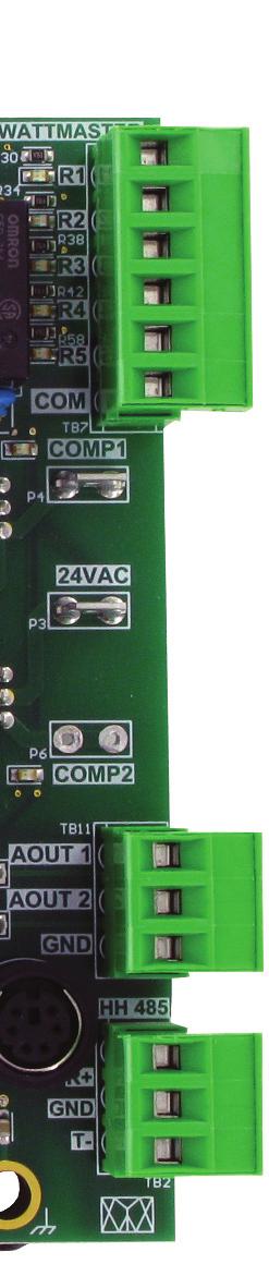
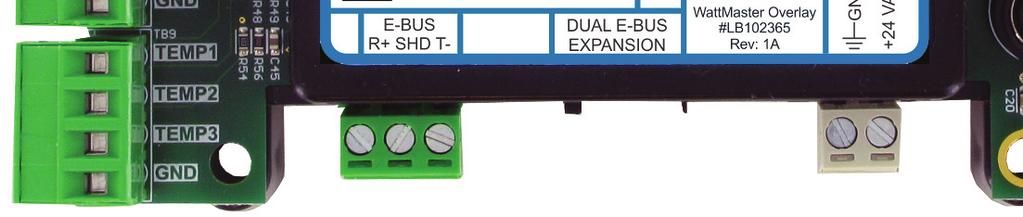
11 TROUBLESHOOTING RSMSD LED Diagnostics Using LEDs To Verify Operation The RSMSD is equipped with LEDs that can be used to verify operation and perform troubleshooting. There are LEDs for communication, operation modes, and diagnostic codes. See Figure 4, below for the LED locations. The LEDs associated with these inputs and outputs allow you to see what is active without using a voltmeter. The LEDs and their uses are as follows: Diagnostic LEDs STATUS - If the software is running, this LED should blink at a rate of 1 blink per second. ALARM - If the module does not receive communications for more than 1 minute, this LED will light up, the relays will turn off, and the Analog Outputs will go to 0 VDC. COMM - Every time the module receives a valid E-BUS request from the VCC-X / VCCX2 Controller, this LED will blink on and then off, signifying that it received a valid request and responded. POWER - This LED will light up to indicate that 24 VAC power has been applied to the controller. Binary Input LEDs BIN1 - This green LED will light up when Compressor Status 1 contact is closed. BIN3 - This green LED will light up when the Outside Coil Temperature switch is closed. BIN4 - This green LED will light up when the Emergency Shutdown switch is closed. Relay LEDs RLY1, RLY 3, RLY5 - These green LEDs will light up when the relays are enabled and will stay lit as long as they are active. Digital Compressor LEDs COMP1 - This green LED will light up when Digital Compressor 1 is unloading. RSMSD STATUS ALARM COMM POWER LEDs RELAY LEDs COMP-1 LED BINARY INPUT LEDs Figure 4: RSMSD LED Locations 11
12 TROUBLESHOOTING Zone OE Suction Pressure Transducer Testing Zone OE Suction Pressure Transducer Testing for R410A Refrigerant The Evaporator Coil Temperature is calculated by converting the Suction Pressure to Temperature. The Suction Pressure is obtained by using the OE Suction Pressure Transducer, which is connected into the Suction Line of the Compressor. Use the voltage column to check the Suction Pressure Transducer while connected to the RSMSD Module(s). The VCC-X/VCCX2 and the RSMSD Module must be powered for this test. Read voltage with a meter set on DC volts. Place the positive lead from the meter on the SP1/SP2 terminal located on the RSMSD Module terminal block. Place the negative lead from the meter on the ground () terminal located adjacent to the SP1/SP2 terminal on the RSMSD Module terminal block. Use a refrigerant gauge set and/or an accurate electronic thermometer to measure the temperature or suction line pressure near where the Suction Pressure Transducer is connected to the suction line. Measure the Voltage at the SP1/SP2 and terminals and compare it to the appropriate chart depending on the refrigerant you are using. If the temperature/voltage or pressure/ voltage readings do not align closely with the chart, your Suction Pressure Transducer is probably defective and will need to be replaced. See the OE Suction Pressure Transducer, Pressure, Temperature, and Voltage Chart for R410A Refrigerant testing. The charts show a temperature range from 20 F to 80 F. For troubleshooting purposes, the DC Voltage readings are also listed with their corresponding temperatures and pressures. Temperature F OE Suction Pressure Transducer Coil Pressure Temperature Voltage Chart for R410A Refrigerant Pressure PSI Signal DC Volts Temperature F Pressure PSI Signal DC Volts Table 2: Coil Pressure/Voltage/Temp for OE Suction Pressure Transducers - R410A Refrigerant 12
13 TROUBLESHOOTING Copeland Discharge Thermistor Temperature Sensor Testing Copeland Discharge Thermistor Temperature Sensor Testing The following sensor voltage and resistance table is provided to aid in checking sensors that appear to be operating incorrectly. Many system operating problems can be traced to incorrect sensor wiring. Be sure all sensors are wired per the wiring diagrams in this manual. If the sensors still do not appear to be operating or reading correctly, check voltage and/or resistance to confirm that the sensor is operating correctly per the table. Please follow the notes and instructions the appear after the chart when checking sensors. Discharge Thermistor Temperature/ Resistance Temp (ºF) Temp (ºC) Resistance (K Ohms) Input (VDC) Discharge Thermistor Temperature/ Resistance Temp (ºF) Temp (ºC) Resistance (K Ohms) Input (VDC) Table 3, cont.: Discharge Thermistor Temperature/ Resistance Thermistor Sensor Testing Instructions Use the resistance column to check the thermistor sensor while disconnected from the controllers (not powered). Use the voltage column to check sensors while connected to powered controllers. Read voltage with meter set on DC volts. Place the - (minus) lead on terminal and the + (plus) lead on the sensor input terminal being investigated. If the voltage is above 4.98 VDC, then the sensor or wiring is open. If the voltage is less than 0.38 VDC, then the sensor or wiring is shorted. Table 3: Discharge Thermistor Temperature/ Resistance 13
14 TROUBLESHOOTING Temperature Sensor Testing Zone Zone Leaving Water Temperature Sensor Testing The following sensor voltage and resistance table is provided to aid in checking sensors that appear to be operating incorrectly. Many system operating problems can be traced to incorrect sensor wiring. Be sure all sensors are wired per the wiring diagrams in this manual. If the sensors still do not appear to be operating or reading correctly, check voltage and/or resistance to confirm that the sensor is operating correctly per the tables. Please follow the notes and instructions that appear after the chart when checking sensors. Temperature Resistance Voltage for Type III 10 K Ohm Thermistor Sensors Temp (ºF) Temp (ºC) Resistance (Ohms) Input (VDC) Temperature Resistance Voltage for Type III 10 K Ohm Thermistor Sensors Temp (ºF) Temp (ºC) Resistance (Ohms) Input (VDC) Table 4, cont.: Temperature/Resistance for Type III 10K Ohm Thermistor Sensors Thermistor Sensor Testing Instructions Use the resistance column to check the thermistor sensor while disconnected from the controllers (not powered). Use the voltage column to check sensors while connected to powered controllers. Read voltage with meter set on DC volts. Place the - (minus) lead on terminal and the + (plus) lead on the sensor input terminal being investigated. If the voltage is above 4.88 VDC, then the sensor or wiring is open. If the voltage is less than 0.05 VDC, then the sensor or wiring is shorted. Table 4: Temperature/Resistance for Type III 10K Ohm Thermistor Sensors 14
15 TROUBLESHOOTING Head Pressure Transducer Troubleshooting Head Pressure Transducer Troubleshooting If you suspect there is a problem related to the head pressure transducer, measurements can be taken at the HP1 and HP2 terminals. Reference Table 5, below. Head Pressure Transducer Chart Voltage Pressure Voltage Pressure Table 5: Head Pressure Transducer Chart 15
16 APPENDIX: CONDENSER OPTIONS Single Condenser For 1 Module Single Condenser for 1 Module See Figure 5, below for Single Condenser for 1 Module wiring. Refer to the figures on the following page for Prism2 configuration, Modular Service Tool Screen selection, and HVAC unit application. OE RSMSD RSM FOR SINGLE DIGITAL COMPRESSOR NOTE: ALL RELAY OUTPUTS ARE NORMALLY OPEN AND RATED FOR 24 VAC POWER ONLY - 1 AMP MAXIMUM LOAD 24 VAC ONLY RLY1 RLY3 RLY5 COMM UNLOAD 24 VAC COMPRESSOR 1 ENABLE CONDENSER 1 ENABLE REVERSING VALVE + DIGITAL COMPRESSOR 1 AOUT1 CONDENSER SIGNAL 1 + COM Connects To VCC-X or VCCX2 Loop Communications Connector When Used On A Split System. Connect to VCC-X or VCCX2 Controller Line Voltage 24VAC Size Transformer For Correct Total Load. RSMSD = 18 VA Figure 5: Single Condenser for 1 RSMSD Module Wiring 16

17 APPENDIX: CONDENSER OPTIONS Single Condenser Per Module Figure 6: Prism2 Condenser Configuration RSMSD Main Configuration Screen #2 - Condenser Options RSMD CONFIGURATION Condenser Options 1 Cond for 1 RSMSD USE < or > TO CHANGE Select the 1 Condenser for 1 RSMD option on the above Hand Held Service Tool Screen. HVAC Unit Application The One Condenser per RSMSD configuration is used with the following HVAC units: B-BOX Air to Air Heat Pump B-BOX WSHP C-BOX Ton C-BOX Air to Air Heat Pump C-BOX WSHP 17
18 APPENDIX: CONDENSER OPTIONS ON/OFF Condenser Options Select this option to have the Condenser Fan turn On/Off with the Compressors. This can also be selected when No Head Pressure Control is required. Select this option if the Condenser Fan cycles On/Off based on the Fan Cycle Head Pressure Setpoints. 18
19 NOTES Notes 19
20 2425 So. Yukon Ave Tulsa, OK Ph: (918) Fax: (918) AAON Part No.: V97750 WM Form: AA-RSMSD-TGD-01C Printed in the USA Copyright April 2018 All Rights Reserved AAON/WattMaster Controls, Inc NW River Park Drive Parkville, MO 64152
RSMV Technical Guide
 RSMV Technical Guide TABLE OF CONTENTS OVERVIEW... 4 Features and Applications... 4 Module Dimensions... 5 INSTALLATION & WIRING... 6 Input Wiring... 6 Suction Pressure Sensor...6 Head Pressure Sensor...6
Water Source Heat Pump Module Technical Guide
 Factory Packaged Controls Tulsa Water Source Heat Pump Module WSHP WSHP Protection Module Module Orion No.: OE334-23-WPM-A NON-DIGITAL COMPRESSORS #1 THRU #4 +5V SUCT. +5V SUCTION PR. SENSOR PRES PRES
Factory Packaged Controls. MHGRV-X Controller Field Technical Guide
 Factory Packaged Controls MHGRV-X Controller Field Technical Guide TABLE OF CONTENTS CONTROLLER OVERVIEW... 3 Features...3 INSTALLATION & WIRING... 4 Important Wiring Considerations...5 MHGRV-X Controller
Factory Packaged Controls. MHGRV-X Controller Field Technical Guide
 Factory Packaged Controls MHGRV-X Controller Field Technical Guide TABLE OF CONTENTS CONTROLLER OVERVIEW... 3 Features... 3 INSTALLATION & WIRING... 4 Important Wiring Considerations... 4 MHGRV-X Controller
VCM-X Controller Technical Guide
 2 2 www.orioncontrols.com VCM-X Controller Technical Guide VCM-X Controller Code: SS1026 & Y200920 Version 2.0 and up; VCM-X Modular Controller: Tulsa - SS1030; Coil - SS1034 VCM-X WSHP Controller: Tulsa
VCM-X Modular E-BUS Controller Technical Guide
 www.orioncontrols.com VCM-X Modular E-BUS Controller Technical Guide VCM-X Modular E-BUS Controller: Tulsa - SS1030; Coil - SS1034 VCM-X WSHP E-BUS Controller: Tulsa - SS1032; Coil - SS1033 Requires Service
Pioneer Gold Controller Technical Guide
 Pioneer Gold Controller Technical Guide Pioneer Gold Controller Code: Version 1.03 Electric Heat Expansion Module Code: Version 1.0 Used with AAON WSHP WV Series Vertical and WH Series Horizontal This
VCC-X Controller Technical Guide
 VCC-X Controller Technical Guide VCC-X Controller Code: SS1079 Version 1.0 and up Requires Service Tool SD Code: SS1063 Version 1.0 and up Requires System Manager SD Code: SS1068 Version 1.11 and up Requires
Digital Precise Air Control - DPAC
 Digital Precise Air Control - DPAC Mode Enable Sensor Options The temperature of this sensor will determine if the unit is in heating, cooling or vent mode during Occupied operation. The following options
Refrigeration Controller Operator s Manual (HRC) PO Box 6183 Kennewick, WA
 PO Box 6183 Kennewick, WA") Refrigeration Controller Operator s Manual (HRC) PO Box 6183 Kennewick, WA 99336 www.jmcvr.com 1-509-586-9893 Table of Contents TABLE OF FIGURES...1 OVERVIEW OF THE HRC CAPABILITIES...2 INSTALLATION AND
Refrigeration Controller Operator s Manual (HRC) PO Box 6183 Kennewick, WA 99336 www.jmcvr.com 1-509-586-9893 Table of Contents TABLE OF FIGURES...1 OVERVIEW OF THE HRC CAPABILITIES...2 INSTALLATION AND
Application and Installation Bulletin for Master-Bilt Refrigeration Superheat Controller Kit Assembly(A ), 120/208/240/1/60, R404A, LT/MT APPS
, 120/208/240/1/60, R404A, LT/MT APPS") Application and Installation Bulletin for Master-Bilt Refrigeration Superheat Controller Kit Assembly(A900-22007), 120/208/240/1/60, R404A, LT/MT APPS Introduction The superheat controller is designed
Application and Installation Bulletin for Master-Bilt Refrigeration Superheat Controller Kit Assembly(A900-22007), 120/208/240/1/60, R404A, LT/MT APPS Introduction The superheat controller is designed
VCB-X Modular Service Tool Technical Guide. VCB-X Controller Code: SS1051 Version 2.0 Requires Service Tool Code: SS1041 Version 2.
 VCB-X Modular Service Tool Technical Guide VCB-X Controller Code: SS1051 Version 2.0 Requires Service Tool Code: SS1041 Version 2.0 and up Table of Contents INTRODUCTION... 3 Modular Service Tool...3 SYSTEM
VCCX2 Controller Operator Interface SD Technical Guide
 www.orioncontrols.com VCCX2 Controller Operator Interface SD Technical Guide VCCX2 Controller Code: SS1088 Version 1.0 & up VAV/Zone Controller Code: SS8011 Requires Service Tool SD Code: SS1063 Requires
RNE Modular Controller Technical Guide
 Factory Packaged Controls RNE Modular Controller Technical Guide RNE Modular Controller: Tulsa - SS1045 Requires Service Tool Code: SS1056 Version 1.0 and up RS-485 COMMUNICATION LOOP. WIRE R TO R, T TO
VCM-X / RNE Controller Operator Interface SD Technical Guide
 VCM-X / RNE Controller Operator Interface SD Technical Guide VCM-X Controller Code: SS1026 VCM-X E-BUS Controller Codes: SS1030, SS1032, SS1033, SS1034 RNE Controller Code: SS1045 VAV/Zone Controller Code:
CB/CF. Series CONDENSERS AND CONDENSING UNITS. Features:
 CB/CF CONDENSERS AND CONDENSING UNITS CF CB Features: 2-70 ton air-cooled condensing units and remote air-cooled condensers Air-source heat pump configurations for energy efficient heating Variable capacity
VCM-X / RNE Operator Interfaces Technical Guide
 Factory Packaged Controls VCM-X / RNE Operator Interfaces Technical Guide VCM-X Controller Code: SS1026, SS1030, SS1032, SS1033, SS1034 Requires System Manager Code: SS1028 Version 1.0 and up Requires
Pioneer Gold Controller Technical Guide. Pioneer Gold Controller Code: Version 1.1 Used with AAON WSHP WV Series Vertical and WH Series Horizontal
 Pioneer Gold Controller Technical Guide Pioneer Gold Controller Code: Version 1.1 Used with AAON WSHP WV Series Vertical and WH Series Horizontal WARNING QUALIFIED INSTALLER IMPROPER INSTALLATION, ADJUSTMENT,
D-PAC. Digital Precise Air Control System. Functionality Factory Testing Ease of Installation Ease of Maintenance Energy Efficiency
 Digital Precise Air Control System D-PAC Functionality Factory Testing Ease of Installation Ease of Maintenance Energy Efficiency AAON 24 South Yukon Avenue Tulsa, Oklahoma 747 (918) 583-2266 Fax (918)
VCCX2 Controller Operator Interface SD Technical Guide
 www.orioncontrols.com VCCX2 Controller Operator Interface SD Technical Guide VCCX2 Controller Code: SS1088 Version 1.0 & up VAV/Zone Controller Code: SS8011 Requires Service Tool SD Code: SS1063 Requires
TWLC - Tempered Water Logic Controller. The Intelligent Control
 TWLC - Tempered Water Logic Controller The Intelligent Control Chiller Controls Features: Up to six (6) stages: individual board for each stage maximizes redundancy. Menu driven access and programming.
FOR SERVICE TECHNICIAN S USE ONLY
 F SERVICE TECHNICIAN S USE ONLY NOTE: This sheet contains important Technical Service Data. Tech Sheet Do Not Remove Or Destroy DANGER Electrical Shock Hazard Only authorized technicians should perform
CONDENSERS AND CONDENSING UNITS
 CONDENSERS AND CONDENSING UNITS CF Series Features: 2-70 ton air-cooled condensing units and remote air-cooled condensers Air-source heat pump configurations for energy efficient heating Variable capacity
Installation and Operation Manual
 Beacon II Refrigeration Systems H-IM-79G April 2018 Part No. 25001401 Replaces H-IM-79F (08/17) Installation and Operation Manual Table of Contents Beacon II Board Layout... 2 Installation Tips... 3 Refrigerant
Installation and Operation Manual
 Beacon II Refrigeration Systems H-IM-79F April 2017 Part No. 25001401 Replaces H-IM-79E (6/11) Installation and Operation Manual Table of Contents Beacon II Board Layout... 2 Installation Tips... 3 Refrigerant
B-40/B-41 Modulating Temperature Controller
 INSTALLATION & OPERATING INSTRUCTIONS B-40/B-41 Modulating Temperature Controller For Raytherm Boilers & Water Heaters H2 514-4001 WH2 2100-4001 Catalog No. 5000.70 Effective: 12-21-11 Replaces: NEW P/N
AE R1 October to 5 Ton ZPS*K6 Copeland Scroll Two-Stage Compressors
 October 2017 1.5 to 5 Ton ZPS*K6 Copeland Scroll Two-Stage Compressors Safety Safety Instructions... 2 Safety Icon Explanation... 2 Instructions Pertaining to Risk of Electrical Shock, Fire, or Injury
TECHNICAL SERVICE DEPARTMENT Technical Service Bulletin Heat Pump Water Heater (Generation 4) Troubleshooting (Effective 1 Nov 2016)
 Troubleshooting (Effective 1 Nov 2016)") No Power,, Fan or Compressor Nothing happens at all. No compressor motor; no fan; no display. 1. See use and care manuals to turn unit ON and set operating MODE. 2. Check for the presence of power at the
No Power,, Fan or Compressor Nothing happens at all. No compressor motor; no fan; no display. 1. See use and care manuals to turn unit ON and set operating MODE. 2. Check for the presence of power at the
User s Manual. TIGER S EYE E-Series Mark V Jockey. TIGERFLOW Systems, Inc Mint Way Dallas, Texas
 User s Manual TIGER S EYE E-Series Mark V Jockey TIGERFLOW Systems, Inc. 4034 Mint Way Dallas, Texas 75237 214-337-8780 www.tigerflow.com TABLE OF CONTENTS Introduction... 4 Sequence of Operation... 5
Installation Manual for CCS Cased Coils with SC, SD, SW Compressor Units and R-410A Refrigerant
 EarthLinked TXV Kit Installation Manual for CCS Cased Coils with SC, SD, SW Compressor Units and R-410A Refrigerant CONTENTS PAGE Pre-Installation 3 Cased Coil Conversion 4 System Start-Up 17 TXV CCS-410-KIT
Installation and Operation Manual
 Quick Response Controller H-IM-QRC April 2018 Part No. 29702401 Replaces H-IM-QRC (08/17) Installation and Operation Manual Table of Contents Heatcraft Quick Response Controller Board Layout... 2 Installation
Model 76 Dehumidifier Control Installation Instructions
 Model 76 Dehumidifier Control Installation Instructions READ AND SAVE THESE INSTRUCTIONS The Model 76 is for use with any dehumidifier as an EXTERNAL CONTROL, including Aprilaire Models 1830, 1850(F)(W),
AIR-COOLED CONDENSING UNIT UNITS PRODUCED AFTER JANUARY, 1996 INDEX SCHEMATIC DIAGRAM FIG. NO.
 wiring diagrams AIR-COOLED CONDENSING UNIT 566D Sizes 120-240 Cancels: New WD 566D.120.1 11/15/96 UNITS PRODUCED AFTER JANUARY, 1996 INDEX UNIT 566D 120-240 ELECTRICAL CHARACTERISTICS (V-Ph-Hz) SCHEMATIC
Hoffman Controls 759-ECM. Installation & Operating Instructions. Introduction. Installation. Pre-Installation Information/ Instruction
 Hoffman Controls Installation & Operating Instructions Introduction CAUTION Failure to read and understand the accompanying instructions and diagrams prior to energizing the Controller may result in permanent
CommStat 6. Controller for Redundant HVAC Systems PRODUCT DATA SHEET
 CommStat 6 Controller for Redundant HVAC Systems PRODUCT DATA SHEET General Description The CommStat 6 HVAC controller is designed for controlling up to six redundant air conditioners in an E-House or
Rev 7 06-APR MultiFlex Condensing Unit Board (CUB-II and CUB-TD) Installation and Operation Manual
 Installation and Operation Manual") 026-1705 Rev 7 06-APR-2010 MultiFlex Condensing Unit Board (CUB-II and CUB-TD) Installation and Operation Manual 1640 Airport Road, Suite 104 Kennesaw, GA 31044 Phone: 770-425-2724 Fax: 770-425-9319 ALL
026-1705 Rev 7 06-APR-2010 MultiFlex Condensing Unit Board (CUB-II and CUB-TD) Installation and Operation Manual 1640 Airport Road, Suite 104 Kennesaw, GA 31044 Phone: 770-425-2724 Fax: 770-425-9319 ALL
Open Protocol Data Communications
 MicroTech Series-100 Centrifugal Chiller Open Protocol Data Communications Information Packet Version 3.2 April, 1996 - C O N F I D E N T I A L - This Document may not be copied or reproduced in any way
HP727S. Single speed swimming pool heat pump controller Operation manual TABLE OF CONTENTS
 HP727S Single speed swimming pool heat pump controller Operation manual TABLE OF CONTENTS 1. General Description 2. Specifications 3. Installation Instructions 4. Electrical Wiring 5. Instrument Wiring
WaterFurnace FX10 Application Guide Reversible Chiller
 2011 WaterFurnace FX10 Application Guide Reversible Chiller Introduction This manual provides information about the FX10 Water Source Heat Pump (WSHP) controller as it relates to dual compressor water
Heat Pumps SA SERIES. Vertical Self-Contained Unit Water-Source Heat Pumps (23-70 tons) Features:
 Features:") Heat Pumps SA SERIES SA Series Vertical Self-Contained Unit Water-Source Heat Pumps (23-70 tons) Features: Vertical self-contained units with capacities from 23 70 tons Direct drive backward curved plenum
Heat Pumps SA SERIES SA Series Vertical Self-Contained Unit Water-Source Heat Pumps (23-70 tons) Features: Vertical self-contained units with capacities from 23 70 tons Direct drive backward curved plenum
DXM2 Digital Heat Pump Controller
 APPLICATION, OPERATION & MAINTENANCE MANUAL DM2 Digital Heat Pump Controller Heat Controller, Inc. 1900 Wellworth Ave. Jackson, MI 49203 (517)787-2100 www.heatcontroller.com Application, Operation, & Maintenance
Your Home. Jacco & Assoc.
 Your Home Fan on with call for heating or cooling Heating on with call from space thermostat Stage as required to maintain The 75F Basics adj. - First stage of heating shall be heat pump Cooling on with
QUICK REFERENCE GUIDE P.C. BOARD/WALL THERMOSTAT FOR 6536A891, 6536B891 & 6536C891 TWO TON PACKAGED HEAT PUMPS
 QUICK REFERENCE GUIDE P.C. BOARD/WALL THERMOSTAT FOR 6536A891, 6536B891 & 6536C891 TWO TON PACKAGED HEAT PUMPS Note: This manual may also be used for 6536-871 series heat pumps if the 6535-3209 Replacement
DXM CONTROLS. DXM Digital Heat Pump Controllers. Application, Operation, & Maintenance. Table of Contents
 Table of Contents DXM CONTROLS DXM Electronic Controls Features Comparison 2 DXM Electronic Heat Pump Controls 3 DXM Physical Dimensions & Layout 4 DXM Controls 5 DXM Service & Application Notes 13 Troubleshooting
H3/V3 Series Horizontal and Vertical Indoor Air Handling Units. Engineering Catalog
 H3/V3 Series Horizontal and Vertical Indoor Air Handling Units Engineering Catalog Table of Contents AAON H3/V3 Series Features and Options Introduction... 6 H3/V3 Base Model Description... 7 Unit Size...
Table of Contents. Service Procedures. Service Procedures. Measuring Superheat (4) Measuring Subcooling (5) Airflow Calculation (6-8)
 Measuring Subcooling (5) Airflow Calculation (6-8)") Table of Contents Refrigeration Cycle Service Procedures Measuring Superheat (4) Measuring Subcooling (5) Airflow Calculation (6-8) Solving Problems Identifying Low System Charge (9-11) Identifying High
Table of Contents Refrigeration Cycle Service Procedures Measuring Superheat (4) Measuring Subcooling (5) Airflow Calculation (6-8) Solving Problems Identifying Low System Charge (9-11) Identifying High
Tempered Water Logic Control OPERATION l TROUBLE SHOOTING
 Tempered Water Logic Control OPERATION l TROUBLE SHOOTING English For MPE Multiple Chiller Units Control Panel TEMPERED WATER SYSTEMS L-2199 Rev. 20080223 Revision: L-2199 20101104 *** IMPORTANT NOTICE
Installation Manual for ETI AVS Series and NON-ETI Air Handlers with SC or SD Compressor Units and R-410A Refrigerant
 EarthLinked TXV Kit Installation Manual for ETI AVS Series and NON-ETI Air Handlers with SC or SD Compressor Units and R-410A Refrigerant CONTENTS PAGE Pre-Installation 3 Air Handler Conversion 4 System
UPM I. Unit Protection Module. Installation and Operation Manual (2015/06)
") UPM I Unit Protection Module Installation and Operation Manual 6 720 220 321(2015/06) 2 Key to Symbols Contents Key To Symbols...2 Warnings...2 Specifications... 3 Unit Protection Module (UPM)....3 Power
UPM I Unit Protection Module Installation and Operation Manual 6 720 220 321(2015/06) 2 Key to Symbols Contents Key To Symbols...2 Warnings...2 Specifications... 3 Unit Protection Module (UPM)....3 Power
PS SERIES PARALLEL RACK SYSTEM GLYCOL CHILLER START UP GUIDE 11/03/2015 Rev 00
 PS SERIES PARALLEL RACK SYSTEM GLYCOL CHILLER START UP GUIDE 11/03/2015 Rev 00 1 Contents INTRODUCTION... 3 WARNING LABELS AND SAFETY INSTRUCTIONS... 4 PARALLEL RACK NOMENCLATURE... 5 GENERAL RACK DESCRIPTION...
SERIES VAC Microprocessor-Based Direct Spark Ignition Control FEATURES APPLICATIONS SPECIFICATIONS DESCRIPTION. Export Information (USA)
") R SERIES 35-70 120 VAC Microprocessor-Based Direct Spark Ignition Control F-35-70 November 2015 FEATURES Safe start with DETECT-A-FLAME flame sensing technology Custom pre-purge and inter-purge timings
R SERIES 35-70 120 VAC Microprocessor-Based Direct Spark Ignition Control F-35-70 November 2015 FEATURES Safe start with DETECT-A-FLAME flame sensing technology Custom pre-purge and inter-purge timings
SERIES VAC Microprocessor-Based Direct Spark Ignition Control with Inducer Blower Relay FEATURES APPLICATIONS SPECIFICATIONS DESCRIPTION
 R SERIES 35-61 24 VAC Microprocessor-Based Direct Spark Ignition Control with Inducer Blower Relay F-35-61 August 2015 FEATURES Safe start with DETECT-A-FLAME flame sensing technology Custom pre-purge
L SERIES UNITS 505,191M. 4/2006 Supersedes 504,908M
 Litho U.S.A. 26 L SERIES UNITS 55,191M 4/26 Supersedes 54,98M M1 7 VERSION 5.2 INTEGRATED MODULAR CONTROL (IMC) GUIDE TO THE M1 7 VERSION 5.2 INTEGRATED MODULAR CONTROL USED IN L SERIES AND S CLASS 3 THROUGH
L SERIES UNITS 504,520M. 10/2001 Supersedes 504,413M
 Litho U.S.A. 2 L SERIES UNITS 54,52M /2 Supersedes 54,4M M 6 VERSION 4. INTEGRATED MODULAR CONTROL (IMC) GUIDE TO THE M 6 VERSION 4. INTEGRATED MODULAR CONTROL USED IN L SERIES THROUGH TON UNITS TABLE
PARAGON Commercial Refrigeration Controls
 PARAGON Commercial Refrigeration Controls ERC 2 Electronic Refrigeration Control The ERC 2 Electronic Refrigeration Control is a microprocessor-based electronic controller designed to control both the
CXM/DXM. Application, Operation & Maintenance Instructions 97B0003N08 Revision: 01/10/05. CXM/DXM Digital Heat Pump Controllers.
 CXM/DXM CXM/DXM Digital Heat Pump Controllers Application, Operation & Maintenance Instructions 97B0003N08 Revision: 01/10/05 Table of Contents CXM / DXM Control Features Comparison 2 Part I - CXM Control
Installation Manual for. Series HWM and Non-ETI HYDRONIC WATER MODULE with SC and SD COMPRESSOR UNITS and R-410 REFRIGERANT
 EarthLinked TXV Kit Installation Manual for Series HWM and Non-ETI HYDRONIC WATER MODULE with SC and SD COMPRESSOR UNITS and R-410 REFRIGERANT CONTENTS PAGE Pre-Installation 3 Hydronic Water Module Conversion
ADDISON SEQUENCE OF OPERATION FOR ALC CONTROL AIRSOURCE HEATPUMP 100% OUTDOOR AIR VERSION Telephone:
 ADDISON SEQUENCE OF OPERATION FOR ALC CONTROL AIRSOURCE HEATPUMP 100% OUTDOOR AIR VERSION 2.0 www.addison-hvac.com Telephone: +1.407.292.4400 1 2 OCCUPIED MODE: When the program control source calls for
Heat Pumps SA SERIES. Vertical Self-Contained Unit Water-Source Heat Pumps (23-70 tons) Features:
 Features:") Heat Pumps SA SERIES Features: Vertical self-contained units with capacities from 23 70 tons Direct drive backward curved plenum and reduced maintenance Double wall rigid polyurethane foam injected panel
Heat Pumps SA SERIES Features: Vertical self-contained units with capacities from 23 70 tons Direct drive backward curved plenum and reduced maintenance Double wall rigid polyurethane foam injected panel
SECTION SEQUENCE OF OPERATIONS FOR HVAC CONTROLS
 PART 1 - GENERAL SECTION 23 09 93 SEQUENCE OF OPERATIONS FOR HVAC CONTROLS 1.1 SUMMARY A. This Section includes control sequences for HVAC systems, subsystems, and other equipment. B. See Division 23 Section
OPERATION AND SERVICE for
 T-313 Manual OPERATION AND SERVICE for 68RM50-100/101 MICROMAX T-313 REV. 07/2012 2012 Mobile Climate Control SAFETY SUMMARY GENERAL SAFETY NOTICES The following general safety notices supplement the specific
DIAGNOSTIC GUIDE DIAGNOSTIC TEST DISPLAY FAULT/ERROR CODES IMPORTANT. Activating the Diagnostic Test Mode. Before servicing, check the following:
 TECH SHEET - DO NOT DISCARD PAGE 1 DIAGNOSTIC GUIDE Before servicing, check the following: IMPORTANT Electrostatic Discharge (ESD) Sensitive Electronics ESD problems are present everywhere. ESD may damage
DIAGNOSTIC GUIDE DISPLAY FAULT/ERROR CODES E1 THERMISTOR OPEN IMPORTANT. Activating the Diagnostic Test Mode. Test Mode Functionality
 TECH SHEET - DO NOT DISCARD PAGE 1 DIAGNOSTIC GUIDE Electrical Shock Hazard Disconnect power before servicing. Replace all panels before operating. Failure to do so can result in death or electrical shock.
L SERIES UNITS 504,908M. 10/2004 Supersedes 9/2004
 Litho U.S.A. 4 L SERIES UNITS 54,98M /4 Supersedes 9/4 M 7 VERSION 5.x INTEGRATED MODULAR CONTROL (IMC) GUIDE TO THE M 7 VERSION 5.x INTEGRATED MODULAR CONTROL USED IN L SERIES AND S CLASS 3 THROUGH 5
Fast Track Troubleshooting
 Fast Track Troubleshooting Models Covered: RF266AD**/XAA French Door Refrigeration IMPORTANT SAFETY NOTICE For Technicians Only This service data sheet is intended for use by persons having electrical,
Subcooling is defined as the point at which liquid is cooled below it s condensing temperature. Example: Refrigerant R404A
 Installation & Service Manual S E C T I O N 26 Enviroguard III ENVIROGUARD III is a patented refrigerant control system that utilizes floating head technology (Nature s Cooling). The amount of liquid refrigerant
UNIT DIGITAL CONTROLS APPLICATION, OPERATION & MAINTENANCE
 DM2 Digital Heat Pump Controller Rev: 3 November 2017 DM2 Overview 3 Physical Dimensions and Layout 4 Layout and Connections 5 Field Selectable Inputs 6 Safety Features 8 Unit Operation Description 10
FOR SERVICE TECHNICIAN S USE ONLY
 FOR SERVICE TECHNICIAN S USE ONLY NOTE: This sheet contains important Technical Service Data. Tech Sheet Do Not Remove Or Destroy DANGER Electrical Shock Hazard Only authorized technicians should perform
MODEL AC-SCC-5 INSTALLATION, OPERATION & MAINTENANCE MANUAL
 5CIM2-0413 W30-AC0056 MODEL AC-SCC-5 INSTALLATION, OPERATION & MAINTENANCE MANUAL Multi-zone Hydronic Chiller Interface Module SECTION 1: INTRODUCTION Unit description... 5 Location... 5 Handling... 5
ACL TC 200 TEMPERATURE CONTROLLER
 TC 200 TEMPERATURE CONTROLLER TC 200 TEMPERATURE CONTROLLER WARNING This manual must be read in its entirety before installation of this controller. Installation must be performed by a qualified technician
REDI CONTROLS, INC. Redi-Purge Model HPP-4A-C3 AUTOMATIC AIR PURGER. High Pressure Refrigeration Systems and Refrigerant Storage Vessels
 REDI CONTROLS, INC. Installation, Operation & Maintenance Manual Literature No. 1078-05-1 Redi-Purge Model HPP-4A-C3 Microprocessor Controlled Purger AUTOMATIC AIR PURGER for use on High Pressure Refrigeration
Warm Case Troubleshooting Guide 9/18/2014
 Introduction Warm cases can be caused by various problems which require thorough troubleshooting. Begin the investigation with questions to store personnel asking for information such as when the last
Pump-Up Controller MODEL 4062
 Pump-Up Controller 4-20mA Input/Scalable Output Seal Fail Monitoring Duplex Pump Alternation Hand-Off-Auto Controls Dual Run-time Meters RS-485/Modbus Communications DESCRIPTION The Model 4062 Pump-Up
Fast Track Troubleshooting
 Fast Track Troubleshooting Models Covered: RF197ACPN French Door Refrigeration IMPORTANT SAFETY NOTICE For Technicians Only This service data sheet is intended for use by persons having electrical, electronic,
SERIES VAC Microprocessor-Based Hot Surface Ignition Control FEATURES APPLICATIONS SPECIFICATIONS DESCRIPTION AGENCY CERTIFICATIONS
 SERIES 35-65 24 VAC Microprocessor-Based Hot Surface Ignition Control F-35-65 August 2015 FEATURES Safe start with DETECT-A-FLAME flame sensing technology Custom pre-purge and inter-purge timings* 120/240
*IG1583EW* Aurora Touch UPC Kit Instruction Guide. Aurora Touch UPC Kit Instruction Guide
 Aurora Touch UPC Kit Instruction Guide For use in single compressor water-to-air equipment utilizing fi rmware UPCSWASTD01-01 Aurora Touch UPC Kit Instruction Guide *IG1583EW* IG1583EW 08/14 Aurora Touch
RELEASE DEVICE CONTROLS
 RELEASE DEVICE CONTROLS RELEASE DEVICE MODEL C+ INSTALLATION MANUAL UL LISTED CANADIAN LISTED CSFM: 7300-48:00 GENERAL DESCRIPTION: MADE IN THE U.S.A. S/N: The LM0-C+ Release Device/Control Panel is a
Pipe Freeze Protection Control SCFP-CO-F130 Installation and Operation Manual
 MANUAL Pipe Freeze Protection Control SCFP-CO-F130 Installation and Operation Manual Model FPT 130 Single Point Freeze Protection Heat Trace Control Table of Contents SCFP-CO-F130 Overview... 3 Installation...
QUICK REFERENCE GUIDE P.C. BOARD/WALL THERMOSTAT FOR 6535D, 6537C, 6538 A&B SERIES TWO TON PACKAGED HIGH EFFICIENCY HEAT PUMPS
 QUICK REFERENCE GUIDE P.C. BOARD/WALL THERMOSTAT FOR 6535D, 6537C, 6538 A&B SERIES TWO TON PACKAGED HIGH EFFICIENCY HEAT PUMPS RV Products A Division of Airxcel, Inc. P.O. Box 4020 Wichita, KS 67204 1-316-832-4357
Part 3 Troubleshooting
 Part Troubleshooting What is in this part? This part contains the following chapters: Chapter See page Troubleshooting 2 Error Codes: Hydro-box 7 Error Codes: Outdoor Units Error Codes: System Malfunctions
Heat Pump Water Heater. Table of Contents
 Table of Contents INTRODUCTION... 3 SAFETY... 3 Electrical... 3 R410a Refrigerant... 3 Scalding... 3 Flammable Vapors... 3 COMPONENT PARTS OF THE HEAT PUMP WATER HEATER... 4 TOOLS... 10 OPERATIONAL MODES...
TECHNICAL MANUAL CVM 20 C 5005 CV/04-99 GB
 Summary 1 CONNECTIONS... 3 1.1 TEMPERATURE PROBES...3 1.2 LOW VOLTAGE DIGITAL INPUTS...3 1.3 LIVE DIGITAL INPUTS...4 1.4 RELAY OUTPUTS...5 2 POWER SUPPLY... 6 3 SERIAL CONNECTIONS... 6 4 SOFTWARE... 7
ModSync Sequencing System Installation & Operation Manual. For use with Fulton Steam Boilers.
 ModSync Sequencing System Installation & Operation Manual For use with Fulton Steam Boilers. Revision 3.0 8/21/2008 - 2 - Table of Contents Introduction Page 4 Features Page 4 Sequence of Operation Page
VT8300 Series Installation Guide 24 Vac Low Voltage
 Vac Low Voltage mercial and Hotel/Lodging HVAC Fan Coil Applications CONTENTS Installation Configurable BI/UI Universal Inputs Overview Setup Screen Display Terminal Identification & Function Terminal
Verasys System Operation Overview Technical Bulletin
 Contents subject to change. Verasys System Operation Overview Technical Bulletin Code No. LIT-12012370 Issued January 2016 Refer to the QuickLIT Web site for the most up-to-date version of this document.
Pump-Down Controller MODEL 4052
 Pump-Down Controller 4-20mA Input/Scalable Output Seal Fail Monitoring Duplex Pump Alternation Hand-Off-Auto Controls Dual Run-time Meters RS-485/Modbus Communications DESCRIPTION The Model 4052 Pump-Down
Installation and Operation Manual
 Cold Storage Solutions Controller (CSS) H-IM-CSS June 2015 Part No. 29702401 Installation and Operation Manual Table of Contents CSS Controller Board Layout... 2 Installation Tips... 3 Refrigerant Line
PAC-2750 ELECTRIC COOLING FAN CONTROLLER
 PAC-2750 ELECTRIC COOLING FAN CONTROLLER IMPORTANT NOTE: The +12V for the controller should NOT be taken from the same circuit as the Fan Power 12V as this can cause the fan to cycle on and off. Required
Safety, Installation, and Operation Manual
 Automatic Steam Humidifier Control Safety, Installation, and Operation Manual READ COMPLETE INSTALLATION INSTRUCTIONS BEFORE STARTING. WARNING This product must be installed by a qualified heating and
RTD TEMPERATURE SENSING SYSTEM
 General Overview RTD TEMPERATURE SENSING SYSTEM The Prime Technology RTD Temperature System 9219-00-0002 is a three-channel temperature measuring system that utilizes two RTD Temperature Sensor inputs
Innovative Design, Performance, & Serviceability
 Innovative Design, Performance, & Serviceability AAON Experience For over 15 years AAON has manufactured Water-Source Heat Pump (WSHP) Rooftop Units, Vertical Self-Contained Units, and Modular Air Handling
User s Information and Installation Instructions
 Outdoor Air Conditioner User s Information and Installation Instructions 2-Stage R-410A Split System These units have been designed and tested for capacity & efficiency in accordance with A.H.R.I. Standards.
TAP v2.10 Version Date: 6/12/13. Document Microprocessor Controller for Tempered Air Products
 Document 475595 Microprocessor Controller for Tempered Air Products Reference Guide for the Microprocessor Controller Please read and save these instructions. Read carefully before attempting to operate
WARNING IMPORTANT. iharmony Zoning System CONTROLS KITS AND ACCESSORIES. Installation Instructions for the iharmony Zoning System (10C16)
") CONTROLS KITS AND ACCESSORIES 2016 Lennox Industries Inc. Dallas, Texas, USA 9/2016 Supersedes11/2015 iharmony Zoning System Installation Instructions for the iharmony Zoning System (10C16) WARNING Improper
CONTROLS KITS AND ACCESSORIES 2016 Lennox Industries Inc. Dallas, Texas, USA 9/2016 Supersedes11/2015 iharmony Zoning System Installation Instructions for the iharmony Zoning System (10C16) WARNING Improper
CM3500 Controller - ClimateMaster DOAS Water-Source Heat Pumps - Rev.: 7 Oct, 2008B
 2 CM3500 Controller - ClimateMaster DOAS Water-Source Heat Pumps - Rev.: 7 Oct, 2008B CAUTION CAUTION - ONLY TRAINED, QUALIFIED PERSONNEL SHOULD INSTALL AND/OR SERVICE CLIMATEMASTER EQUIPMENT. SERIOUS
Field Application of Advanced Residential Air Conditioning Systems
 Field Application of Advanced Residential Air Conditioning Systems Presented By Greg Spencer, Residential Cooling Service Coordinator with Lennox Industries 1 How Ratings Are Established Size of Indoor
Water-Cooled Scroll Compressor Chillers
 Operating Manual OM WGZ-2 Group: Chiller Part Number: 331374501 Effective: March 2005 Supercedes: OM WGZ-1 Water-Cooled Scroll Compressor Chillers WGZ 030AW To WGZ 120AW, Packaged Water-Cooled Chiller
T-32-TS Touchscreen Thermostat. Installation Manual
 T-32-TS Touchscreen Thermostat Installation Manual TABLE OF CONTENTS Introduction...4 Getting Started...5 Installing the Thermostat...6, 8 Disassembly...6 Thermostat Location...6 Mounting the Subbase...6,
TEMPERATURE & PRESSURE CONTROLS
 TEMPERATURE & PRESSURE CONTROLS RANCO LUBE OIL PROTECTION CONTROLS These lube oil protection controls guard pressure-lubricated refrigeration compressors against major damage due to loss of oil pressure.
ENERGY LIGHT USER S GUIDE ENERGY LIGHT USER S GUIDE
 ENERGY LIGHT USER S GUIDE Release January 2001 CONTENTS 1.0 GENERAL CHARACTERISTICS... 4 1.1 MAIN CHARACTERIS TICS... 4 2.0 USER INTERFACE (CODE C5121230)... 5 2.1 DISPLAY... 5 2.2 MEANING OF THE LEDS...