Traditional Fire Gas
|
|
|
- Noel Todd
- 5 years ago
- Views:
Transcription

1 Traditional Fire Gas Traditional Brick Built Open Gas Fire & Gas Burner Installation and Operating Instructions Note: Flue System Casing Flue system may require to be double lined to comply. Refer to ASNZS:2918: Flue pipe casing Note: Brick Out Guide Details When purchasing the fire bricks the bricking guide will come with the bricks. NOTE : Traditional open fires are the least efficient fires available and can lack in heat output. Visit for specs, DWGs and PDF uploads of fires Fire, flue system and instructions to comply with ASNZS 2918:2001 & Building Code C/AS1 7.5 Open Fires Keep these instructions for further reference. Ensure that you have the correct and current installation details for the Warmington Fire. Installation The Warmington unit is to be installed by a certified Warmington installer or an approved NZHHA installation technician. IMPORTANT Read all the instructions carefully before commencing the installation. Failure to follow these instructions may result in a fire hazard and void the warranty. 1

 No: Warmington")
 75X115X230mm Varied Other")


 Fill")

2 COMPONENTS REQUIRED FOR CONSTRUCTION Supplied as Trad. Gas Firebox No: Traditional Firebox 1 NOT Supplied (sold separately) No: Warmington Fluekit 1 Traditional Firebox Adaptor 1 Fire Bricks (H40) 75X115X230mm Varied Other Sizes Available Gas Burner 1 Fire Brick Refractory Mortar 1 Autoclaved Aerated Concrete (AAC) Heat cell 1 Constructed on site Caitec Venting System *Caitec Steel Brick *Caitec Perf. Extension 2 Flashing System 1 Non Combustible Cladding Back Air Brick 1 (Promat-Superlux-Brick-Stone etc) Fill /Crush (vermiculite etc) Aluminium Tape. 3M Scotch Brand Exhaust Sealant Gas & Electrical Work Onsite Fire / Flue kit / Flashing Installation Installation of Brickwork Council Permit 2


3 GENERAL INFORMATION Like the traditional brick back fires of yesteryear, the Warmington Traditional Fire is built with the experience and techniques of the past. These make a grand statement in the home. However, they can lack in efficiency. The gas version of the traditional fire benefits from the aesthetic appeal of a brick backed fire, while remaining convenient and simple to use. The gas version is installed with a wood flue kit and wood based clearances, so that the fire can be retrofitted to a wood fire at a later date without additional expense. POINTS TO CONSIDER PRIOR TO INSTALLATION Location of the fire: Open fires are better located at one end of a room or area, as they project the heat away from their opening. The Topography of the Land: The slope and position of the land in relation to the home has a bearing on how the wind will interact with the fire and flue system. Care needs to be taken to ensure that the flue termination is in the correct position to maximise performance. The Prevailing Wind. Care needs to be taken to ensure that the flue termination is in the correct position, as wind gusts that hit the flue and cowl system may overcome the cowl and draught back down the flue into the home. This can be a combination of down draught and high pressure. Pressure Differential, Venting & External Air into the Building: All fires need air to burn and draw correctly. Kitchen fans, air conditioning units, high wind zones, and naturally forming draught spaces can all have an effect on the pressure differential from inside the building to the outside. A lower pressure in the building may induce a draught down the flue system and back into the building, causing the fire to smoke or spill into the building. Care needs to be taken at the design and installation stage to adequately vent the building to ensure that there is always a neutral or positive pressure at the fireplace and a negative pressure at the flue outlet (a mechanical system can be added to aid this if necessary). This will ensure that the draught in the flue system is always to the outside. Wind Noise: You may encounter wind noise in some installations. It is recommended to use an enclosed chase with a chimney pot to help reduce noise. There will always be some noise from the flue systems of all fireplaces. CAITEC ROOM AIR REPLACEMENT TECHNOLOGY Fitted in every Warmington traditional fireplace is Warmington s own Caitec technology. The Caitec system draws air from an external air source (outside the room) to ensure that the open fire has a steady supply of pre-heated combustion air. This maximises efficiency while maintaining a pressure equilibrium in the home, reducing the risk of back draughting. The following references are used in this document for the Caitec system and venting requirements: 1. Air enters the cavity (and heat cell if one is used) through external vents in the surrounding structure. Excess air drawn in will cool the cavity structure. 2. The external air travels through the Caitec system within the firebox and enters the combustion chamber via two perforated air bricks (one on each side). 3. Combusted gases and particulates are exhausted through the flue system. 4. The excess air supply that entered the cavity (in 1), that has warmed and risen due to natural convection, exits through the vents at the top of the cavity (or through the liner and out of a venting cone in the case of venting through the flashing)


4 SERIAL NUMBER Serial number plate location, on inside face GENERAL REQUIREMENTS FLUED GAS APPLIANCES: All gas fires requiring Warmington Flue Systems shall be installed to the requirements of the current standards and shall be appropriately designed and constructed to permit safe and effective use. This appliance must be flued to the outside atmosphere. All Warmington fires must be Installed with a minimum of 3.6m of approved Warmington gas flue and liners. GAS TYPE: All gas fires shall operate safely on the gas type specified on the appliance and shall comply with the requirements of The Gas Act ELECTRICAL REQUIREMENTS: All gas fire appliances installed with mains supplied electrical components for associated use with these appliances, and must comply with The Electricity Regulations ELECTRONIC CONTROL SYSTEMS: Any gas fire appliance installed with manual or programmable electronic control system shall be tested and/or approved by a recognised person or Authority. SEISMIC RESTRAINTS: All fires used for domestic and commercial purposes shall be firmly secured (unless defined as portable or mobile) to prevent dislodgement from their point of fixture or installation during seismic activity. Such restraint must be of a reasonable expectation. GAS CONNECTION: A gas certificate must be obtained for the installation and commissioning of this appliance and flue system. Check that the gas type specified on the data plate is correct for the available supply (LPG or NG). A copper gas supply capable of supplying the correct MJ/h, should be brought into the rear of the installation cavity through the hole provided. A flare nut is provided on the burner for gas connection to the appliance. SAFETY CONSIDERATIONS Your Warmington Traditional Gas fire operates on the principle of dual radiant and convected heat. It is important to observe the following precautions associated with the heating appliance. Do not cover or restrict the fireplace upper or lower vents in any way as this may result in a build-up of hazardous gases within the room. The fire is not intended for the drying of clothing, bedding etc Avoid installing this appliance in high traffic areas, strong draughts or near drapes or furniture The use of an approved fireguard is recommended for the protection of young children Avoid using aerosols when the appliance is operating Avoid anyone leaning against or lying directly in front of the fire while operating Do not place anything objects into or against the gas fire at any stage The fire may release a small amount of smoke on its first start up which may take 1or 2 hours to dissipate. This is part of the curing process so ensure there is adequate ventilation within the room. Always use a registered gasfitter or electrician for installation and maintenance work. Always use certified gas cylinders that have been tested and are safe to use Never modify your gas appliance or its settings from those specified by the manufacturer WHAT TO DO IF YOU SMELL GAS Open windows and doors Do not light any gas appliance Do not use any electrical appliance or switches Do not use the telephone in your home Leave the building; shut off the domestic gas supply valve (beside your meter) Call your gas supplier/gasfitter or the fire service for further advice. 4


5 Your purchase of the Warmington traditional fire gas burner (included in the price of the firebox) comes with multiple options for lighting/ heat settings. The most affordable option is the SG option, which is a manual start, manual adjustment option, working much like a barbeque. Alternatively, Warmington offers several electronic options- ON-OFF with a switch at the wall to operate the fire, or ON-OFF-HIGH-LOW with two settings for heat output. Furthermore, a fully adjustable electronic EG option is available, supplied with remote control. OPERATION OF A WARMINGTON SG GAS FIRE (MANUAL START) To light: Open the front cover by pulling it outwards Push in the ignition control switch and hold in the PILOT position for 5-10 seconds until you can hear the gas come through the pipe, making sure the ignition switch is pressed in firmly. To strike the igniter, turn anti clockwise to the *STAR position (with the ignition switch still firmly pressed in) until you hear the pilot ignite with a click. Repeat this process 2 or 3 times if necessary. Once the pilot flame is lit, hold this position for 3-5 seconds, then gently let the ignition switch out and set the flame control to high. It may take a few seconds for the burner to light all the way across. Once the flame is established, adjust to the desired setting and close the cover. To shut down: Open the cover by pulling it outwards. Turn the control ignition switch to PILOT and the flame bed will extinguish. Pilot light may be left on and the pilot flame will still burn. To fully extinguish, turn to the OFF position before closing the cover. OPERATION OF A WARMINGTON EG ELECTRONIC GAS FIRE AS SHOWN FROM THE FRONT OF THE BURNER This control panel is located on the bottom left hand side of your Warmington decorative gas fire. Press and release the power button. This will start the electronic spark and the power LED will be on permanently. The pilot will ignite first and once this is on, it will ignite the main burner. Pressing and releasing the power button again will switch off the appliance. When the appliance is turned on again, the gas fire will resume the previous flame and fan settings, unless the appliance was switched off due to power failure. In the circumstance of a power failure the Remote Control System will return to the default settings which is a low flame and the fan turned off. If the gas fails to light, the appliance it will go into lock out mode, after trying to ignite for 1 minute (approx.). In lock out mode the power LED will remain illuminated. To start the appliance again, press and release the power button twice after the gas supply resumes. REMOTE CONTROL Your remote control has all the features of the control receiver situated on the front panel of the burner. By pressing the timer button, the power LED will start flashing and after 30 minutes the appliance will shut off automatically. By pressing the timer button again within the 30 minute period, this will reset the timer and the power LED will stop flashing. Press and hold the + button to increase the main burner flame. Press and hold the - button to decrease the main burner Flame. By holding the + or - flame button for up to seconds, this will increase or decrease the main burner flame to it s max or min. The Warmington decorative gas fire has a 3 Speed Fan and its operated independent from the main burner. This is done by pressing and releasing the fan + or button will increase or decrease the fan speed. The LED on the front panel will indicate the fan settings at low, medium, or high speed. Pressing and releasing of the button will lower the speed until the fan is turned off. 5


6 INSTALLATION Important Notes: This is a general installation guide only. Contact a NZHHA Installer for installation advice or go to then select Members & follow instructions to find a certified NZHHA SFAIT installer. Install to AS/NZS 2918:2001. Install to manufacturer s specifications. All new installations require a permit. For special requirements concerning materials (timber mantle and surrounds) within close proximity of Warmington products, please contact your local Warmington technical consultant or designated installer. STAGE 1: FRAME CONSTRUCTION PROCEDURE FOR BUILDER Mark out flue centre on floor. Mark out heat cell clearance requirements. Construct framing or block surround according to relevant minimum dimensions as referenced on pages 6 to 9. After framing surround is complete, construct plinth to required height (see page 8 for details). 1.1 WARMINGTON TRADITIONAL FIREBOX DIMENSIONS Description TFG 1500 TFG 1800 Firebox width A Firebox height B Firebox depth C Flange width D Flange height E Adaptor height F Distance between flues Z Minimum Flue Height Flue height 3600 Measured from top of adaptor B + F AUTOCLAVED AERATED CONCRETE (AAC) HEAT CELL DIMENSIONS Description TFG 1500 TFG 1800 Heat cell width G Heat cell height H Heat cell depth I To centre of flue J Flue diameter K Liner diameter L Heat cell clearance width M Heat cell clearance depth N Heat cell clearance height O Heat cell panel thickness T


7 1.3 TIMBER FRAMING & TRIM OUT DETAILS - HEAT CELL CLEARANCE Description TFG 1500 TFG 1800 To centre of flue J Flue diameter K Liner diameter L Heat cell clearance width M Heat cell clearance depth N Heat cell clearance height O Hearth width P Hearth projection Q Chimney chase clearance X Chimney chase clearance Y Note: Non-combustible cladding eg. 10mm promina board, 10mm Supalux, latex plaster etc. (not supplied). Note: Centreline of flue is NOT in centre of alcove PLAN, FRONT ELEVATION & CROSS SECTION Note: 50mm clearance from the flue liner to timber framing is required 7


8 1.5 BLOCK ENCLOSURE 1 (WITH AAC HEAT CELL) Description TFG 1500 TFG 1800 Hearth width P Hearth projection Q Block clearance width R Block clearance depth S Block enclosure height U To centre of flue V Chimney chase clearance X Chimney chase clearance Y Note: With AAC heat cell, timber framing can be in direct contact with brick alcove Note: Centreline of flue is NOT in centre of alcove Note: Two 100mm diameter vents (minimum) required at base of block for Caitec system and cavity venting. Venting to external air recommended. Cut holes in block structure as required. 1 AAC 8
 heat")
9 1.6 BLOCK ENCLOSURE 2 - WITHOUT AAC HEAT CELL Description TFG 1500 TFG 1800 Hearth width P Hearth projection Q Solid poured top width RR Solid poured top depth SS Block enclosure height TT To centre of flue UU Chimney chase clearance X Chimney chase clearance Y Note: Without Autoclaved Aerated Concrete (AAC) heat cell, timber framing & any combustibles to be spaced 50mm away from blockwork, all around until 2400mm height. Note: Centreline of flue is NOT in centre of alcove Note: Two 100mm diameter vents (minimum) required at base of block for Caitec system and cavity venting. Venting to external air recommended. Cut holes in block structure as required. 1 9


 with vermiculite fill/ crush Fit adaptor to firebox using supplied M8 bolts, nuts and washers.")

10 1.8 HEARTH & PLINTH CONSTRUCTION DETAILS Notes: For combustible flooring an insulating hearth and plinth of 75mm Autoclaved Aerated Concrete (AAC) is required. To keep finishing on hearth flush with the plinth, the plinth should be offset from the ground by the thickness of the finishing material. Offset for hearth Hearth Plinth Offset STAGE 2: INSTALL PROCEDURE FOR NZHHA CERTIFIED INSTALLER AND BRICKLAYER Note: Recommended order of operations only. Installation order may vary depending on nature of build and/ or availability of bricklayer. Fit firebox to plinth in correct position using seismic restraint flanges on sides of firebox. Bricklayer to install bricks. Refer to section 2.2 to install Caitec system during brick out. If installing fire with optional log-lighter, follow additional instructions 2.3 and 2.4. Fill cavity at back of firebox (behind installed brickwork) with vermiculite fill/ crush Fit adaptor to firebox using supplied M8 bolts, nuts and washers. Ensure that exhaust sealant is used between fire and adaptor. Construct autoclaved aerated concrete (AAC) enclosure around traditional firebox. Insert grate. Grate dimensions are to be specified after brick out is complete. Fit flue system. See page 16 for details. Fit cowl and flashing system TF 1500 TF 1800 Bags of vermiculite fill required BRICKS & BRICK OUT DETAIL The fire bricks are sold separately from the firebox. Purchase from an associated retailer. The bricking guide will come with the purchase of the bricks. Brick size and refractory: The standard brick out is the stretcher bond style. However, other styles can be bricked according to your liking. Some bricklayers prefer to us their own refractory. Please check with the bricklayer. Bricks come in a standard size of 230 x 115 x 75mm. 25 mm and 40 mm thick bricks are available, at a higher cost however due to more bricks being necessary for the brick out. The figures below show different pattern styles that are bricked with the standard brick size of 230 x 115 x 75mm. Stretcher Bond Pattern Stack Bond Pattern Herring Bone Pattern 10
 vents are used to extract outside air into the cavity (and into the firebox).")
 is sufficient.")

.")

11 2.2 CAITEC SYSTEM AND BACK AIR BRICK INSTALLATION The Caitec system ensures that pre-heated external air is available for combustion, improving efficiency while reducing the risk of back draughting. Warmington requires that 2x 100mm diameter (or equivalent cross sectional area or larger) vents are used to extract outside air into the cavity (and into the firebox). Such vents should be accounted for at the design stage, and should be placed below the elevation of where combustion occurs within the firebox. Locating the vents flush with the profile of the base of the firebox (or close to) is sufficient. For the Warmington Traditional Gas fire, an additional artificial brick is supplied which is to be installed in the place of one of the bricks in the centre of the fireback. This is to provide an air channel for the gas and electronic feeds, which exit through the back of the firebox. To install: For bricklayer: Lay up the base layer of bricks, first two layers of the wings, leaving a one brick gap in the side of the second layer of each wing, about mm forward of the front face of the fireback (or where the gas burner is expected to be placed). Additionally, lay up the first layer(s) of the fireback, leaving one brick s worth of a gap in the centre of the base (or where the gas feed is located). For the bricklayer or builder: Cut down the perf extensions, specific to the length required and taper of the wings. Place the two perf extension pieces with the steel bricks attached, in situ within the firebox. Mark out the outline of where the perf extensions butt up against the perf sides (on the internal sides of the firebox). Remove the extensions and cover the surrounding area of the perf sides with aluminium tape. Additionally, cover the perf extensions with aluminium tape before placing them back into the cavity. Place the back air brick in situ, so that the front face sits flush with the front face of the fireback. Complete brick out, bricking around the inserted artificial bricks Slide steel bricks into place to complete Caitec installation (front face of steel bricks should sit flush with bricks). Perf extension Back Air Brick Steel brick Note: Caitec system to be installed on both left and right sides of firebox as standard 1. Lay up base layer of bricks, as well as first two layers of wings and first layer of fireback Mark up outline of perf extension in situ Cover relevant area of perf sides, as well as perf extensions with aluminium tape Completed brick out with Caitec and 11
 Power Panels are required for basic heat cell construction as shown in detail Firebox with Hebel Surround. *Visit www.warmington.co.nz site for AAC instructions (PDF download). 2.3.")
12 2.3 AAC HEAT CELL ASSEMBLY The heat cell is constructed around the firebox, using 75mm Hebel aerated autoclaved concrete (AAC) panels. (2400x600x75) Power Panels are required for basic heat cell construction as shown in detail Firebox with Hebel Surround. *Visit site for AAC instructions (PDF download) TFG 1500 HEAT CELL ASSEMBLED TFG 1800 HEAT CELL ASSEMBLED Note : Two 100 x 100mm holes in the bottom back Hebel panels provide venting for Caitec air system. Note: Heat cell assembly details When purchasing the AAC heat cell kit, the assembly guide will come with the kit. Note: If solid plastering the heat cell structure, it is recommended to use a fibreglass mesh with a latex plaster to minimise the chance of the plaster cracking. (see your plasterer for correct materials and applications). *Note: If plastering the Heat Cell structure, it is recommended to use a fibreglass mesh with a latex plaster to minimise the chance of the plaster cracking. (See your plasterer for correct materials and applications). 12

13 STAGE 3: GAS BURNER INSTALLATION AND TESTING FOR GASFITTER 3.1 GAS SPECIFICATIONS Tested to current gas standards: AS/NZS 5601:2010, NZS 5266:2014, NZS/AS 4558:2013, NZS/AS 3645 NOTE : All test pressures are tested by an independent test lab Inlet pressure not to exceed 4.0 kpa MODEL TFG 1500 TFG 1800 LPG Nominal Pressure kpa 2.75 kpa 2.75 kpa Nominal Injector Size mm TBC TBC Burner Pressure High kpa Burner Pressure Low kpa MJ/h TBC TBC Flame Effect Output Only Effect Effect Supply Pipe Size dia min 1/2 1/2 Natural Gas Nominal Pressure kpa 1.5 kpa 1.5 kpa Nominal Injector Size mm TBC TBC Burner Pressure High kpa Burner Pressure Low kpa MJ/h TBC TBC Flame Effect Output Only Effect Effect Supply Pipe Size (minimum diameter) 1/2 1/2 Lab. Test No TBC TBC Lab. Test Dates TBC TBC ESS Declaration No n/a n/a 3.2 POSITIONING THE BURNER The burner should be positioned in the centre of the firebox. Care should be taken to ensure the burner is placed in line with the Caitec vents. The burner sits by self weight on the bricks and does not need to be bolted to the bricks. There is a removable artificial steel brick at the back of the firebox, with two holes for gas feed and electronics feed where applicable. 3.3 VERMICULITE APPLICATION Coarse vermiculite must be used so as not to block the gas outlet holes Apply a thin layer of vermiculite over the burner, just enough to cover the burner tray. Note: If the burner flame is uneven, the vermiculite may need to be changed or sifted to remove the smaller pieces that can block the burners holes. The smaller pieces can cause uneven burn and the unit to run dirty. 13


14 3.4 COALS AND LOGS Care should to be taken when handling coals & logs due to the carbon on the coals, which can stain the surroundings. Warmington suggests wearing gloves when handling the coals and logs, and using metal tongs when hot. Bottom row: Assemble 2 bottom rows of coals onto the vermiculite base. Top Row: Assemble 2 top rows of coals onto the bottom row. 1: Bottom Row 2: Top Row Slide R & LH grate pins into holes located on the burner side Total number of coals will vary per model. Each coal should be randomly positioned with the rough face facing outward. Ensure coal positioning does not directly block the 3- flame pilot. The placement of the coals & logs may vary to make an even flame pattern. Logs and twigs may be scattered to achieve best visual effect. Fit burner grate by sliding R & L side metal pins on grate, into holes located on burner side plates, as shown. Number of Coals per Row Number of Rows Total Coals Model Bottom Top Bottom Top Total TFG TFG TFG CONTROL VALVE ADJUSTMENT SG MANUAL CONTROL VALVE Control valves are factory set but may require adjustment onsite Turn appliance off & remove front plastic cover on igniter. Pull cover to slide off. Unscrew test nipple on the burner manifold & fit the test gauge securely - see diagram. To set the high: Light the burner & turn to high - then adjust the high screw to the desired pressure - see specs. To set the low: Light the burner & turn to low - then adjust the low screw to the desired pressure - see specs. Extinguish appliance, remove test equipment and secure test nipple. Check valve & burner for correct operation & check fire for gas leaks. 14
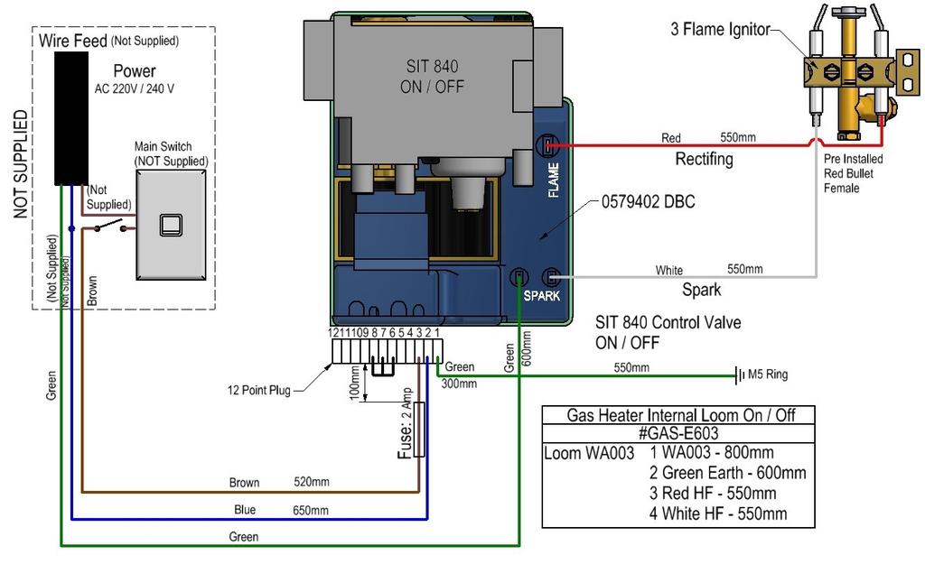
15 3.5.2 ON-OFF ELECTRONIC CONTROL VALVE Note: Any alterations to pressure are to be carried out by a certified gasfitter Light appliance and check the pressure to the hi kpa value in the table for maximum output. If adjustments are necessary, remove the dust cap on the control value. The pressure adjustment screw is on the front side of the gas control valve and is factory set. WARNING: Ensure that the dust cap is replaced after adjustment. Pressure Setting: Turn the burner on with the switch and wait for full ignition. Using a standard screwdriver, screw the adjusting screw clockwise to increase the outlet pressure, or screw counter clockwise to decrease the pressure to the desired settings. Set the pressure to the hi kpa value in the table for maximum output. Modulator Harness Connections test point outlet 1/2 BSPT gas inlet SIT 840 Control Valve test point inlet adjustment screw 1/2 BSPT gas outlet After checking the pressure, turn the unit off, remove manometer from the test point and tighten the test point screw. Ensure to check for gas leaks. Turn the appliance on and off a few times to check ignition. When satisfied that the appliance is working correctly, fit the front panel assembly back to the gas burner. Note : Ensure you peel the protective plastic coating from any stainless steel components if fitted. All burner aerations are factory preset and cannot be adjusted. If you are unable to get the unit to operate correctly, refer to troubleshooting before contacting your Local Service Contact. It may take approximately 2 hours of operation for the coals/logs or river rocks to achieve their full flame pattern and glow. During the initial burn period, some smoke and smell may be experienced. Because of this, run the appliance on the high position in a well ventilated room until these dissipate. 15
16 16

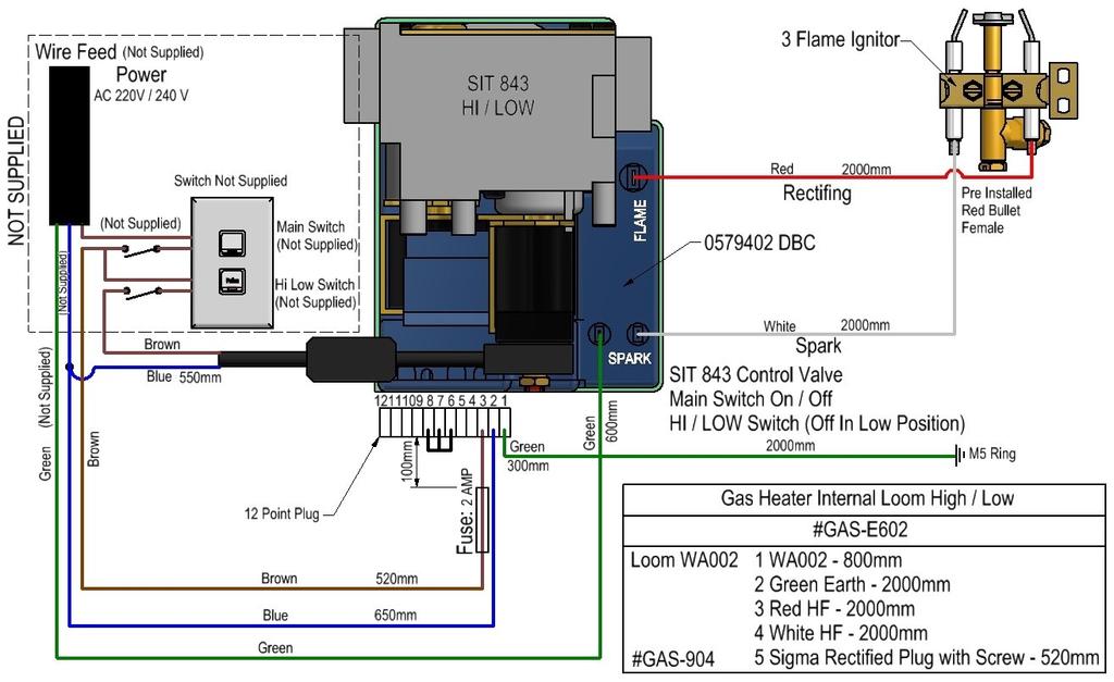
17 3.5.3 ON-OFF-HIGH-LOW ELECTRONIC CONTROL VALVE Note: Any alterations to pressure is to be carried out by a Certified Gas Fitter. Light appliance and check the pressure to the hi kpa value in the table for maximum output. If adjustments are necessary, remove the dust cap on the control value. The pressure adjustment screw is on the front side of the gas control valve and is factory set. WARNING: Ensure that the dust cap is replaced after adjustment. Pressure Setting: Turn the burner on with the switch and wait for full ignition. Using a standard screw driver, screw the adjusting screw clockwise to increase the outlet pressure, or screw counter clockwise to decrease the pressure to the desired settings. Set the pressure to the hi kpa value in the table for maximum output. The burner will operate any pressure between the hi and the low pressures. HI / LOW Harness Connections test point inlet test point outlet Nut A High setting adjustment screw SIT 843 Control Valve Screw B 1/2 BSPT Gas outlet Low setting adjustment screw After checking the pressure, turn the unit off, remove manometer from the test point and tighten the test point screw. Ensure to check for gas leaks. Ensure power is off & reconnect modulator harness connection in the main harness. Turn the appliance on and off a few times to check ignition. When satisfied that the appliance is working correctly, fit the front panel assembly back to the gas burner. Note: Ensure you peel the protective plastic coating from any stainless steel components if fitted. All burner Aerations are factory preset and cannot be adjusted. If you are unable to get the unit to operate correctly, refer to troubleshooting before contacting your local service contact. It may take approximately 2 hours of operation for the coals/logs or river rocks to achieve their full flame pattern and glow. During the initial burn period, some smoke and smell may be experienced. Because of this, run the appliance on the high position in a well ventilated room until fumes dissipate. 17
18 18

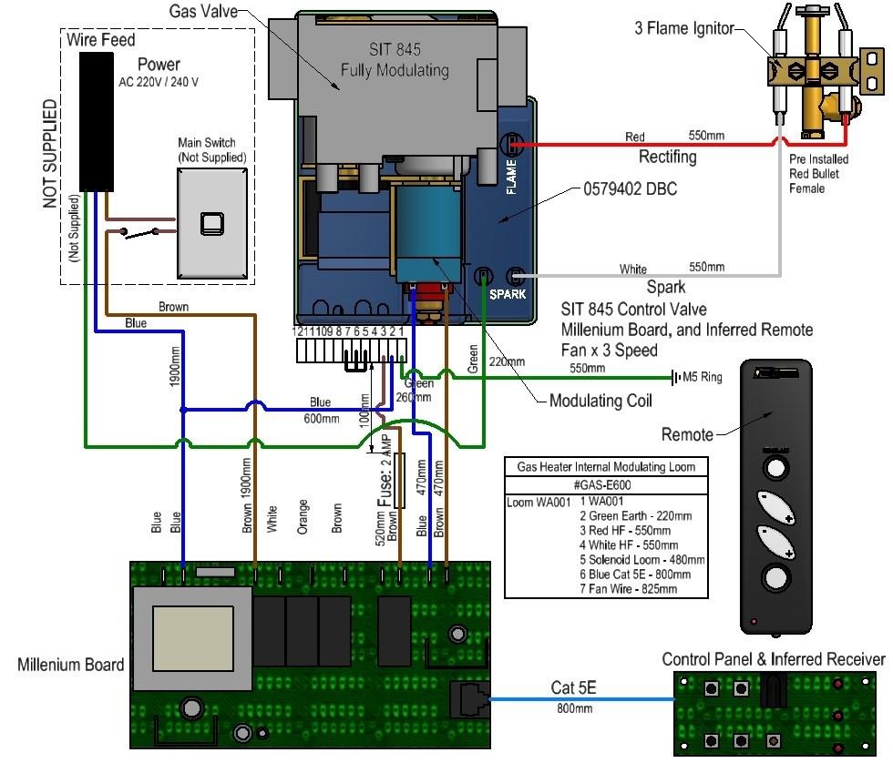
19 3.5.4 EG FULLY ELECTRONIC CONTROL VALVE Ensure gas supply and power supply (caution 240V) to the unit Refer to data plate on this specification for settings. The data plate is attached to the under carriage of the burner. Remove front grate and ensure the CAT5 cable to the control receiver is still connected. Loosen the jet test point and attach manometer (digital is preferred). The test point is on the right hand side of the gas burner, as shown below. Gas Test Nipples for SG / EG Fires Note: Any alterations to pressure is to be carried out by a certified gasfitter Light appliance, adjust to high flame setting and check pressure, adjust to low flame and check pressure. If adjustments are necessary, remove the cap. The pressure adjustment screw and nut are on the front side of the gas control valve and are factory set. High Pressure Setting: Set the modulator to maximum condition. Screw in nut A to increase the outlet pressure then screw nut A out to decrease the pressure to the desired settings. Use 10mm spanner. Low Pressure Setting: Turn off the power to the modulator (by disconnecting the modulator harness connection at the valve - see wiring.) and, keep nut A stationary. Use a screwdriver to screw in screw B to increase the pressure and screw it out to decrease the pressure. Carefully replace the modulator plastic cap. WARNING: To ensure the correct operation of the modulator it is necessary that the plastic cap is returned to its original location. Modulator Harness Connections DIAGRAM B Screw B 19

20 After checking the pressure, turn the unit off, remove manometer from the test point and tighten the test point screw. Ensure to check for gas leaks. Ensure power is off & reconnect modulator harness connection in the main harness. Turn the appliance on and off a few times to check ignition. When you are satisfied that the appliance is working correctly, fit the front panel assembly back to the gas burner. NOTE: Ensure you peel the Protective Plastic Coating from any stainless steel components if fitted. All burner aerations are factory preset and cannot be adjusted. If you are unable to get the unit to operate correctly, refer to troubleshooting before contacting your local service contact. It may take approximately 2 hours of operation for the coals/logs or river rocks to achieve their full flame pattern and glow. During the initial burn period, some smoke and smell may be experienced. Because of this, run the appliance on the high position in a well ventilated room until the fumes dissipate. 20
21 21


22 3.6 ADJUSTMENT OF PILOT Note to Gasfitters The 3 flame pilot may need adjustment after a period of running time on set up as the increase in heat in the fire will induce a higher draught in the fire, and may pull in flame away from the file tube causing the fire to shut down. When the base screw is removed, gas will leak from the outlet. Ensure that the pilot is not adjusted or the screw is removed when the fire is burning. Adjustment of pilot - 3 Flame: Unscrew base screw as shown in Diagram 2. Insert a screwdriver as shown in Diagram 3 and adjust the adjustment screw up inside the 3 Flame Pilot to adjust the flame height. The flame must always be passing over the electrodes &/or file tube on either side. Replace the base screw and check for leaks. 3 Flame Pilot in Correct operation of 3 Flame Pilot 3.7 COMMISIONING AND TESTING Read all the instructions before commissioning. Install coals and logs and burner before commission. Light appliance and check HIGH/LOW settings. Check operation of appliance and adjust to suit. Adjust control valve setting if required. After a period of running (30min plus) check the setting of the pilot and adjust if required. See specs for details. Extinguish appliance, remove test equipment and secure test nipple. Check for gas leaks. Note: The control valves are factory set and should not require adjustment. Gasfitter to carry out standard testing for commission: Spill test taken at top of opening with smoke or smoke match Leak testing appliance and joints Correct operation of the burner and coal and log lay out Test gas pressures high and low, drop test on supply line 5 second light time across burner, Other testing that may be required Ventilation requirements to the standards Clean and or touch up paint of fire box and burner Hand over to client, tests to comply to relevant standards 22
 enclosure and hearth to customer s requirements (e.g. paint/ tiles etc).")


23 STAGE 4: FINISHING PROCEDURE FOR BUILDER Construct hearth to required thickness Close in AAC enclosure and chimney chase (if in timber alcove) Finish autoclaved aerated concrete (AAC) enclosure and hearth to customer s requirements (e.g. paint/ tiles etc). Due to the expansion and contraction of metal fireplaces, a 3mm gap between the flange and the finished surround should be maintained. Remember to install required 2 x 100mm diameter vents for Caitec system Construct mantle if required 4.1 COMBUSTIBLE MANTLE CLEARANCES : REF BUILDING CODE 4.2 HEARTH CLEARANCES Important Note: A hearth extension ABOVE the curved minimum requirement line on the graph for a selected model of traditional fire is an acceptable hearth extension. A hearth extension BELOW the curved minimum requirement line is NOT acceptable. Important Note: For raising trad. fires on combustible floors, at (dimension B) height of 420mm & above the hearth extension (dimension A) of 380mm must be maintained. This is for all traditional fire models. 23

24 SINGLE 3.6m FLUE KIT DETAILS FLUE DETAILS DIMENSIONS Minimum Flue Height Flue Height 3600 Measured From Top of Adaptor B + F Note: FLUE SYSTEMS Casing. Flue system may require to be Doubled lined to comply. Ref ASNZS:2918: Flue pipe casing Flue Details No: TF 800 TF 1000 TF 1200 Cowl Top Spider Cone Flue Diameter Liner Diameter Spacer 3 300/ / /450 NOTE: Ensure that a Standard Tested Warmington Flue system is used on the Warmington fires. FLUE SYSTEM INSTALLATION GUIDE This is a general installation guide only Contact a NZHHA Installer for Installation Advice or go to then select Members & follow Instructions, to find a Certified NZHHA SFAIT 1. Install the first length of flue pipe with the crimped end down, inside the Adaptor collar, ensure that the flue pipe is sealed into the collar with exhaust sealant. Rivet the flue in 3 places around the Adaptor collar. Place a spacer around the flue pipe approximitaly150mm above the adaptor collar. Secure in position by tightening the screw and nut. 2. Install the second length of flue pipe with the crimped end down and fit by riveting in at least 3 places around the flue pipe joint. Ensure that the flue is sealed into position with sealant. 3. Install the first section of flue pipe liner with the Crimped end up, over the flue pipe and over the spacer that is fixed to the flue pipe. This spacer will keep the liner concentric about the flue pipe. 4. Position flue spacer at the flue pipe joint for every length of Flue pipe and Liner. 5. Repeat the Steps from 1 4 to the installed required height of the flue system. The flue system is to comply with ASNZS 2918: a the flue pipe shall extend not less than 4.6m above the top of the floor protector. b the minimum height of the flue system within 3 m distance from the highest point of the roof shall be 600mm above that point. c the minimum height of the flue system further than 3 m from the highest point of the roof shall be 1000mm above the roof penetration. d no part of any building lies in or above a circular area described by a horizontal radius of 3 m about the flue system exit. NOTE: The last length of flue pipe needs to extend past the liner so that when the top spider and the Flashing cone are fitted, that the flashing cone and the flue pipe are flush, or that the flue pipe is 5mm lower that the Flashing cone. 5. Fit the Top Spider into position, ensure that the legs of the spider are fitted inside the liner and that the spider is positioned hard down onto the liner and tighten with the screw and nut. 6. Place the Flashing cone over the flue pipe and press hard down onto the Top Spider. (Note that the Flue pipe and the Flashing Cone are either flush or the Flue pipe is 5mm Lower than the Flashing cone.) Ensure that the Flashing cone is clear for the venting from the Liner and the flue pipe. 7. Fit the Cowl to the top of the flue pipe. The Cowl, Flashing cone, and the Flue pipe can be secured to each other with the uses of a stainless steel self tapping screw. This will allow the Cowl to be removed for cleaning. Flue system may require Bird Proofing due to the installation and locations, discuss this with your installer for the best advice. If the Flue system is installed into a Chimney Chase, allow for air vent as close to the top of the chase as practical, or allow venting through the Chimney Chase Flashing. A Venting Flashing cone and a 25mm gap around the Liner with a Venting Flashing Cone-Spider can be used. 24

 an additional flue pipe baffle is")

25 FLUE PENETRATION VENTED THROUGH ALCOVE (SINGLE LINED FLUE SYSTEM) FLUE PENETRATION VENTED THROUGH ALCOVE (DOUBLE LINED FLUE SYSTEM) FLUE PENETRATION VENTED THROUGH TOP FLASHING Note: Flue system casing. Flue system may require to be Doubled lined to comply. Ref ASNZS:2918: Flue pipe casing Notes: External requirements: refer to AS/NZS2918: All flashing to comply with E2. Install Flue system to AS/NZS2918:2001 When using a rubber or bitumen flashing (Butynol, Dectite) an additional flue pipe baffle is required. All external air vents & ceiling penetrations must be bird proofed with permanently fixed screens. Additionally, all external air vents and ceiling penetrations are to be vermin and rodent proof. Test Report Number Date of Report 04/ th July / th July / th July


26 CHIMNEY CHASE FLASHING DETAILS SETTING ADD COWL AND FLASHING CONE HEIGHT Note: Flashing Spigot height is determined by the Insulation that is fitted under the Flashing See Details at bottom of page. STEP 1 STEP 2 STEP 3 CHIMNEY CHASE FLASHING AND AIR VENTILATION OPTIONS VENTING THROUGH CHIMNEY CHASE No Insulation under flashing VENTING THROUGH FLASHING Insulation under flashing 26


27 FLUE HEIGHT MINIMUM DETAILS Note: FLUE SYSTEMS Casing. Flue system may require to be Doubled lined to comply. Ref ASNZS:2918: Flue pipe casing The flue exits are to comply to ASNZS 2918 : D View FRAME OUT AND TRIM OUT DETAILS FOR CHIMNEY CHASE Option X Singled Lined Flue System Option Y Double Lined Flue System 27
28 ADDITIONAL INFORMATION GENERAL NOTES These installation and operating instructions should be kept in a safe place. Should you require another copy, download from the Warmington website: The appliance and flue system must be installed in accordance with relevant standards and the appropriate building codes. MAINTENANCE Warmington Industries recommend annual servicing of your gas fire by an approved Warmington gasfitter. Clean the bricks of the fire using a stiff brush as required. Warmington does not recommend using water or a wet cleaning product due to the porous quality of the bricks. WARNINGS WARNING: THE APPLIANCE AND FLUE SYSTEM SHALL BE INSTALLED IN ACCORDANCE WITH AS/NZS 2918 AND THE APPROPRIATE REQUIREMENTS OF THE RELEVANT BUILDING CODE OR CODES WARNING: APPLIANCES INSTALLED IN ACCORDANCE WITH THIS STANDARD SHALL COMPLY WITH THE REQUIREMENTS OF AS/NZS 4013 WHERE REQUIRED BY THE REGULATORY AUTHORITY, I.E. THE APPLIANCE SHALL BE IDENTIFIABLE BY A COMPLIANCE PLATE WITH THE MARKING TESTED TO AS/NZS ANY MODIFICATION OF THE APPLIANCE THAT HAS NOT BEEN APPROVED IN WRITING BY THE TESTING AUTHORITY IS CONSIDERED TO BE IN BREACH OF THE APPROVAL GRANTED FOR COMPLIANCE WITH AS/NZS CAUTION: MIXING OF APPLIANCE OR FLUE-SYSTEM COMPONENTS FROM DIFFERENT SOURCES OR MODIFYING THE DIMENSIONAL SPECIFICATION OF COMPONENTS MAY RESULT IN HAZARDOUS CONDITIONS. WHERE SUCH ACTION IS CONSIDERED, THE MANUFACTURER SHOULD BE CONSULTED IN THE FIRST INSTANCE. CAUTION: CRACKED AND BROKEN COMPONENTS MAY RENDER THE INSTALLATION UNSAFE. Industries 1994 LTD PO Box 58652, Botany 2163, Auckland 28
SG Burner Only
 SG 700-780-900-1100 Burner Only SG Gas Burner into a Warmington SI Wood Open Fire Installation Guide Only Warmington SI Open Wood Firebox. Warmington SG Gas Burner. Traditional Grate & Burner Pure Grate
Debonaire DUPLO
 Debonaire DUPLO 1200-1600-2000-2400-2800 Custom Fire DUPLO Gas Burner Installation Instructions Flue Liner Promina Board Cladding Non-Combustible Firebox Venting Burner NOTE: TV Above option available
Debonaire VIRAGE LH
 Debonaire VIRAGE LH 1200-1600-2000-2400- Custom Fire VIRAGE LH Gas Burner Installation Instructions Flue Liner Firebox Venting Non-Combustible Promina Board Cladding Burner NOTE: T.V. Option Available
Gas Flare & Rail Burners Gas Flare & Rail Burners Installation Instructions
 Gas Flare & Rail Burners Gas Flare & Rail Burners Installation Instructions Gas Flare Rail Burner (Ash Pan ) Rail Burner (Grate ) OPTION 1 OPTION 2 and 3 Installation to Comply with NZS 5262 / 5261:2003
Installation Manual EF5000 AUS & NZ
 Installation Manual EF5000 AUS & NZ This manual is ONLY for fires with a serial No. from 80600 to 80999. Important: The appliance shall be installed in accordance with; Local gas fitting regulations Municipal
Installation Manual EF5000 NZ
 Installation Manual EF5000 NZ Important: The appliance shall be installed in accordance with; Local gas fitting regulations Municipal building codes AS/NZS 5601.1.1:2010 Gas Installation Any other relevant
SPECIFICATION & INSTALLATION GUIDE FOR MASPORT LE4000 PROVINCIAL INSERT FIRE, NEW ZEALAND MODEL
 SPECIFICATION & INSTALLATION GUIDE FOR MASPORT LE4000 PROVINCIAL INSERT FIRE, NEW ZEALAND MODEL Manufactured in New Zealand by: GLEN DIMPLEX AUSTRALASIA LIMITED PO Box 58-473 Botany Auckland 2163 Ph: 0800
Studio Stove 14. Studio Stove clean air approved wood burner Installation instructions
 Studio Stove 14 Studio Stove clean air approved wood burner Installation instructions The Warmington Airback The Warmington Studio Stove is fitted with an Airback. The Airback is designed to be left in
THE INSTRUCTIONS IN THIS MANUAL APPLY TO KENT GAS FIRES. CONTENTS:-
 THE INSTRUCTIONS IN THIS MANUAL APPLY TO KENT GAS FIRES. THE MODELS COVERED ARE:- For use with Natural Gas:- KENT ESTATE NG, KENT ULTIMA NG For use with Liquid Propane Gas (LPG):- KENT ESTATE LP, KENT
Please read this booklet, for the safe installation of your MULTI FUEL FIRE
 Please read this booklet, for the safe installation of your MULTI FUEL FIRE The Appliance and Flue System must be installed in accordance with AS/NZS2918. Consult with the building authority having jurisdiction
Studio Stove 0.95 Grams Per Kilo
 Studio Stove 0.95 Grams Per Kilo Studio Stove Clean Air Approved Wood Burner Installation Instructions Visit www.warmington.co.nz for Spec s, DWG s and PDF uploads of Fires Fire, Flue System and instructions
Installation Instructions Horizon Natural Draft Electronic Ignition Gas Fireplaces
 Installation Instructions Horizon Natural Draft Electronic Ignition Gas Fireplaces Installation Instructions Horizon Natural Draft Electronic Ignition 3 Sided Gas Fireplaces Natural Draft Electronic Ignition
XANDER INSERT WOOD BURNER
 A division of Terry Young Ltd, New Zealand INSTALLATION INSTRUCTIONS for XANDER INSERT WOOD BURNER Clean Air Sub 1.0 Non Clean Air (Rural) 26 JUNE 2017 These instructions are for MASONRY installations
Eastside Installation Guidelines and Operating Instructions January 2018
 Eastside Installation Guidelines and Operating Instructions January 2018 Technical details subject to change Please ensure you have the latest specifications Part One Living Flame Livingflame.co.nz INSTALLATION
Studio Oven. Studio Oven - Woodburner Installation Instructions. Visit for Spec s, DWG s and PDF uploads of Fires
 Studio Oven Studio Oven - Woodburner Installation Instructions Visit www.warmington.co.nz for Spec s, DWG s and PDF uploads of Fires Fire, Flue System and Instructions to Comply with ASNZS 2918:2001 Keep
Pizza Oven with Stand
 Pizza Oven with Stand Cooks up to 3 pizzas at a time Use to cook a variety of food Easy clean vitreous enamel interior Model No. P0104 Powerful 22MJ/h stainless steel burner Viewing window and temperature
IB1100 and IB850 Installation Manual AUSTRALIAN EDITION
 IB1100 and IB850 Installation Manual AUSTRALIAN EDITION Important: The appliance shall be installed in accordance with; This installation instruction booklet Local gas fitting regulations Municipal building
Installation & Operation Manual Fascia / Firebox / Build-In Cabinet
 Installation & Operation Manual Fascia / Firebox / Build-In Cabinet MANUFACTURED BY CRIGHTON engineering creativity 100 Neilson Street, Onehunga, Auckland, NZ Ph: 09 634 1865 / Fax 09 634 6804 www.crighton.co.nz
Installation Manual. ST900 Direct Vent Gas Fireplace. Important: NZ / AUS EDITION
 ST900 Direct Vent Gas Fireplace Installation Manual NZ / AUS EDITION Important: The appliance shall be installed in accordance with; This installation instruction booklet Local gas fitting regulations
Dovre 250 Cast Iron Gas Stove
 Dovre 50 Cast Iron Gas Stove NATURAL GAS AND LPG INSTALLATION, SERVICING AND USER INSTRUCTIONS THIS PRODUCT IS FOR USE ONLY IN GREAT BRITAIN AND IRELAND These instructions are to be left with the customer,
Part 1: Installation Instructions for WAGENER SPARKY (Please keep these Instructions for future Reference)
") Part 1: Installation Instructions for WAGENER SPARKY (Please keep these Instructions for future Reference) Important Message to the Owner Please read fully the Operation & Maintenance Instructions with
Part 1: Installation Instructions for WAGENER SPARKY (Please keep these Instructions for future Reference) Important Message to the Owner Please read fully the Operation & Maintenance Instructions with
INSTALLATION & OPERATING MANUAL
 MAGIGLO SERIES INSTALLATION & OPERATING MANUAL The Magiglo series of decorative fires are suitable to be installed into a masonry or approved prefabricated fireplace and are designed to operate with Natural
THE INSTRUCTIONS IN THIS MANUAL APPLY TO MASPORT BOSTON (Flued) AND CALGARY (Flueless) GAS FIRES.
 AND CALGARY (Flueless) GAS FIRES.") THE INSTRUCTIONS IN THIS MANUAL APPLY TO MASPORT BOSTON (Flued) AND CALGARY (Flueless) GAS FIRES. THE MODELS COVERED ARE:- MG 3000 STD NG, and MG 3000 FLS NG for use with Natural Gas MG 3000 STD LP, and
THE INSTRUCTIONS IN THIS MANUAL APPLY TO MASPORT BOSTON (Flued) AND CALGARY (Flueless) GAS FIRES. THE MODELS COVERED ARE:- MG 3000 STD NG, and MG 3000 FLS NG for use with Natural Gas MG 3000 STD LP, and
Fundamentals of a gas fire New Zealand. August 2017
 Fundamentals of a gas fire New Zealand August 2017 1 INDEX Fundamentals of a gas fire 3. Ventilation To room space 4. Mechanical ventilation & Smart home connection 5 8. Finish 9 10. Finish face details
Cardrona Cooker. Cardrona Cooker - wood burner Installation Instructions. Visit for spec s, DWG s and PDF uploads of fires
 Cardrona Cooker Cardrona Cooker - wood burner Installation Instructions Visit www.warmington.co.nz for spec s, DWG s and PDF uploads of fires Fire, Flue System and Instructions to Comply with ASNZS 2918:2001
Rhode Island PIT FIRES
 Rhode Island PIT FIRES HELLO from all of us at Living Flame THE RHODE ISLAND PIT FIRE RANGE So you want a little something special for your yard. We ve created these with you in mind (Besides, being inside
Part 1: Installation Instructions for WAGENER LEON- Multi Fuel
 Part 1: Installation Instructions for WAGENER LEON- Multi Fuel (Please keep these Instructions for future Reference) Important Message to the Owner Please read fully the Operation & Maintenance Instructions
Wok Cookers Instruction Manual
 Wok Cookers Instruction Manual Part No. DC100-09 Single Burner Wok Cooker Part No. DC200-09 Double Burner Wok Cooker IMPORTANT It is IMPORTANT that you read these instructions carefully and understand
ZERO CLEARANCE Z-SYSTEM
 Innovation. Performance. Efficiency. ZERO CLEARANCE Z-SYSTEM INSTALLATION INSTRUCTIONS Standard, Edwardian & Victorian Models Large & Medium Sizes Please read and save these instructions in a safe place
ZERO CLEARANCE BOX INSTALLATION INSTRUCTIONS
 ZERO CLEARANCE BOX INSTALLATION INSTRUCTIONS HINS-195 Manufactured for G.L.G. Australia Pty Ltd. Building A2, Campus Business Park, 350-374 Parramatta Road Homebush, NSW, 2140 Read these instructions carefully
Studio 3 Steel 2, Glass Fronted with Log-effect fuel bed and Vermiculite lining STUDIO GAS FIRES
 Studio 3 Steel 2, Glass Fronted with Log-effect fuel bed and Vermiculite lining STUDIO GAS FIRES STUDIO GAS FIRES A Warm Welcome Nothing creates an inviting atmosphere quite like a Gazco fire. The centrepiece
Installation & Service Instructions
 Part No. 966/9350/1 02 Potterton Housewarmer Illusion ASD - G.C. NO. 37 590 16 966 Inset DGF with ILLUSION FACIA Potterton Housewarmer Stratton ASD - G.C. NO. 37 590 17 966 Inset DGF with STRATTON FACIA
IB850 and IB600 Installation Manual AUSTRALIAN EDITION
 IB850 and IB600 Installation Manual AUSTRALIAN EDITION Important: The appliance shall be installed in accordance with; This installation instruction booklet Local gas fitting regulations Municipal building
Internet Version for Reference Only INDUCED DRAFT COMMERCIAL WATER HEATERS SUPPLEMENT INSTRUCTIONS TO PART #
 INDUCED DRAFT COMMERCIAL WATER HEATERS SUPPLEMENT INSTRUCTIONS TO PART #238-39387-00 THIS INSTRUCTION SUPPLEMENT IS ONLY INTENDED TO GIVE INSTALLATION INSTRUCTIONS AND INFORMATION RELATED TO THE INDUCED
ZERO CLEARANCE Z-SYSTEM
 Innovation. Performance. Efficiency. ZERO CLEARANCE Z-SYSTEM INSTALLATION INSTRUCTIONS Standard, Edwardian & Victorian Models Large & Medium Sizes Please read and save these instructions in a safe place
MODELS LFP4218/LFP6018 TOP VENT GAS FIREPLACE
 MODELS LFP4218/LFP6018 TOP VENT GAS FIREPLACE PFS APPROVED FOR NATURAL GAS OR PROPANE GAS Z21.50-2014 If your plans do not allow for the venting system as outlined previously in the installing chimney/vent
FOR YOUR SAFETY FOR OUTDOOR USE ONLY PROPANE GAS. Model No. AH2069ODS, AH2063ODS
 Model No. AH2069ODS, AH2063ODS The ideal solution for extending the season of outdoor entertaining Creates a stylish and attractive ambience Direct ignition Includes a safety tip-over switch that halts
Important: Appliance must be installed with a Rinnai approved flue system.
 Important: Appliance must be installed with a Rinnai approved flue system. This appliance shall be installed in accordance with: - Manufacturer s installation instructions - AS/NZS 5601 Gas Installations
Conventional Flue. Instructions for Installation. For use in NZ (New Zealand). IMPORTANT
. IMPORTANT") Logic HE Range Conventional Flue Instructions for Installation For use in NZ (New Zealand). IMPORTANT INSTALLATION AND SERVICING MUST ONLY BE CARRIED OUT BY AUTHORISED PERSONNEL. THE OUTER CASING, FRONT
Logic HE Range Conventional Flue Instructions for Installation For use in NZ (New Zealand). IMPORTANT INSTALLATION AND SERVICING MUST ONLY BE CARRIED OUT BY AUTHORISED PERSONNEL. THE OUTER CASING, FRONT
Installation guide Compact 2
 Installation guide Compact 2 Models: RIBF2N/RIBF2L Standard frame Traditional frame Installer, please note: The gas and electrical plate of the unit is not required when attaching the traditional frame,
Patio Heater Model No. GM and GM
 Patio Heater Model No. GM124-003 and GM124-004 FEATURES: The ideal solution for extending the season for outdoor entertaining Maximum output 39.6 MJ/hr Direct ignition Adjustable heat output Safety tip-over
Riva Studio. Built-In Convector. Instructions for Installation & Servicing. For use in AU & NZ (Australia and New Zealand)
") Riva Studio Built-In Convector Instructions for Installation & Servicing For use in AU & NZ (Australia and New Zealand) These products are tested in accordance with AS/NZ 4012:1999, AS/NZ 4013:1999 and
Riva Studio Built-In Convector Instructions for Installation & Servicing For use in AU & NZ (Australia and New Zealand) These products are tested in accordance with AS/NZ 4012:1999, AS/NZ 4013:1999 and
St. Croix Greenfield Installation Manual
 St. Croix Greenfield Installation Manual Table of Contents General Information... 1 Installation Check List... 2 Approved Installations... 3 Exhaust Venting... 4 Venting - Approved Materials... 4 Venting-Typical
Southern Series. Free-Standing Wood Burner
 Southern Series B E A D C INDUSTRIES 1994 LTD Ensure That You Have The Correct Installation Details For The Size of The Warmington Fire That is to be Installed. 1. Double Skin The Southern Series Firebox
Studio 2. Balanced Flue with Thermostatic Remote Control. Installation Instructions. For use in AU (Australia). IMPORTANT
. IMPORTANT") Studio 2 Balanced Flue with Thermostatic Remote Control Installation Instructions For use in AU (Australia). IMPORTANT INSTALLATION AND SERVICING MUST ONLY BE CARRIED OUT BY AUTHORISED PERSONNEL. THE OUTER
Studio 2 Balanced Flue with Thermostatic Remote Control Installation Instructions For use in AU (Australia). IMPORTANT INSTALLATION AND SERVICING MUST ONLY BE CARRIED OUT BY AUTHORISED PERSONNEL. THE OUTER
Manual. Monaco. Gas Fires. Owners & Installation PLEASE KEEP THESE INSTRUCTIONS FOR FUTURE REFERENCE
 Owners & Installation Monaco Manual Gas Fires PLEASE KEEP THESE INSTRUCTIONS FOR FUTURE REFERENCE WARNING Improper installation, adjustment, alteration, service or maintenance can cause injury or property
FREESTANDING GAS HEATER
 FREESTANDING GAS HEATER July 2001 OPERATIONS, MAINTENANCE & WARRANTY INFORMATION 25-07-01 Page 1 of 23 Operation Instructions for Eros Free Standing Gas Fire July 2001.doc CONTENTS: PAGE INTRODUCTION 3
Rambo CAST IRON RING BURNERS OPERATING INSTRUCTIONS. C40LP 3 Ring Burner C50LP 4 Ring Burner
 Rambo CAST IRON RING BURNERS OPERATING INSTRUCTIONS C20LP 1 Ring Burner C30LP 2 Ring Burner C40LP 3 Ring Burner C50LP 4 Ring Burner IMPORTANT: READ THESE INSTRUCTIONS FOR USE CAREFULLY. KEEP THESE INSTRUCTIONS
INSTANT INFRARED HEATER GAS HEATER IDEAL FOR CAMPING AND DOMESTIC USE
 INSTANT INFRARED HEATER GAS HEATER IDEAL FOR CAMPING AND DOMESTIC USE IMPORTANT SAFETY INFORMATION As with all gas appliances, misuse of this appliance or failure to fully follow these instructions may
SHAMIC SHEETMETAL (AUST.) PTY. LTD.
 PTY. LTD.") Coonara Grange - Domain, Slimline & Freestanding Grange Domain Grange Slimline Grange Freestanding with Pedestal Option Grange Freestanding with Table Top Option CUSTOMER OPERATING INFORMATION & INSTALLATION
Coonara Grange - Domain, Slimline & Freestanding Grange Domain Grange Slimline Grange Freestanding with Pedestal Option Grange Freestanding with Table Top Option CUSTOMER OPERATING INFORMATION & INSTALLATION
SIME FORMAT WALL HUNG BOILERS MODEL 34i AND MODEL 34e. cod A
 cod. 6272262A GENERAL DATA Heating Data Heat Output Input (Adjustable) (Adjustable) Format 34i 11.2 34KW 45 145MJ/hr Format 34e 11.2 34KW 45 145MJ/hr General Specifications FORMAT 34i 34e Main burner injectors
Area Heater AH100 Series
 Area Heater AH100 Series FEATURES: The ideal solution for extending the season for outdoor entertaining Creates a stylish and attractive ambience Casts an approximate 3 to 5 metre circle of radiant sun-like
SOUTHWEST FIREBIRD MFG SONORAN UNVENTED Model 36/42/48
 SOUTHWEST FIREBIRD MFG SONORAN UNVENTED Model 36/42/48 INSTALLATION INSTRUCTIONS PREFABRICATED MODULAR MASONRY- UNVENTED SONORAN 36/42/48TO BE USED WITH UNVENTED GAS LOGS. SAVE THIS BOOK This book is valuable.
Studio. Freestanding Cassette Range. Instructions for Installation & Servicing. For use in AU & NZ (Australia and New Zealand)
") Studio Freestanding Cassette Range Instructions for Installation & Servicing For use in AU & NZ (Australia and New Zealand) These products are tested in accordance with AS/NZS 4012:1999, AS/NZS 4013:1999
Studio Freestanding Cassette Range Instructions for Installation & Servicing For use in AU & NZ (Australia and New Zealand) These products are tested in accordance with AS/NZS 4012:1999, AS/NZS 4013:1999
----FIREPLACES---- Installation Instructions Horizon Natural Draft Electronic Ignition Gas Fireplaces. 24/10/2017 Ver. 15
 ----FIREPLACES---- Installation Instructions Horizon Natural Draft Electronic Ignition Gas Fireplaces 24/10/2017 Ver. 15 1 125mm 125mm Installation Instructions Kemlan Natural Draft Electronic Ignition
Studio. Built-In Convector. Instructions for Use, Installation & Servicing. For use in AU (Australia)
") Studio Built-In Convector Instructions for Use, Installation & Servicing For use in AU (Australia) These products are tested in accordance with AS/NZS 4012:2014, AS/NZS 4013:2014 and AS/NZS 2918:2001 and
Studio Built-In Convector Instructions for Use, Installation & Servicing For use in AU (Australia) These products are tested in accordance with AS/NZS 4012:2014, AS/NZS 4013:2014 and AS/NZS 2918:2001 and
Clear Installation guide
 Clear 40010631-0938 ENG Installation guide ENG 1.1 1.2 1.3 A 1.4 1.5 1 < < < < A B 2.1 2.2 2.3 C 2.4 2.5 2 < < < < 3.1 3.2 3-3 3 < < < < Inhoudsopgave 1 Introduction... 6 2 Safety instructions... 6 3 Installation
HAWK GAS STOVE. Installation and Servicing Instructions
 HAWK GAS STOVE Installation and Servicing Instructions Please leave this instruction booklet with the user after the installation is complete. Leave the system ready for operation and instruct the user
GLOBAL 40 CF FITTING INTO A CONVENTIONAL CLASS 1 CHIMNEY
 INSTALLATION INSTRUCTIONS GB/IE GLOBAL 40 CF FITTING INTO A CONVENTIONAL CLASS 1 CHIMNEY DRU VERWARMING B.V. HOLLAND 957.669.00 CONTENTS Site: 3 Important 3 Foreword 4 Instructions for installation 4 Ventilation
Esse B MODEL Roomheater with boiler WOOD BURNING ONLY MODEL
 Esse 700 27B MODEL Roomheater with boiler WOOD BURNING ONLY MODEL Esse Stoves & Cookers Long Ing. Barnoldswick, Lancashire BB18 6BN. United Kingdom. Tel: + 44 (0) 1282 813235 F: + 44 (0) 1282 816876 enquiries@esse.com
Installation and Operating Instructions for the following Woodsman models
 Issued: July 2009 Installation and Operating Instructions for the following Woodsman models These instructions should be read in conjunction with the flue installation instructions and drawings supplied
Course introduction 2. 1 Appliances and fuels 3. 2 Combustion Legislation Air supply Flues and chimneys Commissioning 83
 Solid Fuel Installer Learning Manual BPEC0051 Contents Contents Page Course introduction 2 1 Appliances and fuels 3 2 Combustion 25 3 Legislation 29 4 Air supply 47 5 Flues and chimneys 57 6 Commissioning
Riva Studio. Inset Convector Cassette MODELS: RVS-1/RVS-2/RVS-3. Instructions for Use, Installation and Servicing For use in New Zealand (NZ).
.") Riva Studio Inset Convector Cassette MODELS: RVS-1/RVS-2/RVS-3 Instructions for Use, Installation and Servicing For use in New Zealand (NZ). IMPORTANT: All installations to comply with AS/NZS2918:2001
Riva Studio Inset Convector Cassette MODELS: RVS-1/RVS-2/RVS-3 Instructions for Use, Installation and Servicing For use in New Zealand (NZ). IMPORTANT: All installations to comply with AS/NZS2918:2001
Corn Flame Energy Corn Stove Model 3000
 Corn Flame Energy Corn Stove Model 3000 Installation and Operation Guide Read thoroughly before starting installation Save this manual for future reference SAFETY NOTICE If this stove is not properly installed,
----FIREPLACES---- Installation Instructions Horizon Portrait Power Flue Gas Fireplaces
 ----FIREPLACES---- Installation Instructions Horizon Portrait Power Flue Gas Fireplaces Power Flue approved for the following models: SINGLE SIDED MODELS SUITABLE GAS BURNER OPTION 700 PORTRAIT 700 Mk2
----FIREPLACES---- Installation Instructions Horizon Power Flue Gas Fireplaces
 ----FIREPLACES---- Installation Instructions Horizon Power Flue Gas Fireplaces Power Flue approved for the following models: SINGLE SIDED MODELS CANTILEVER SUITABLE GAS BURNER OPTION 700 Low Line 700 Mk2
Malm Fireplaces, Inc. 368 Yolanda Avenue, Santa Rosa, CA (707) Fax: (707)
 Fax: (707)") Malm Fireplaces, Inc. 368 Yolanda Avenue, Santa Rosa, CA 95404 (707) 523-7747 - Fax: (707) 571-8036 info@malmfireplaces.com Fire Drum 2 Tested to U/L Standards 1482 and 737 Assembly And Installation Instructions
Malm Fireplaces, Inc. 368 Yolanda Avenue, Santa Rosa, CA 95404 (707) 523-7747 - Fax: (707) 571-8036 info@malmfireplaces.com Fire Drum 2 Tested to U/L Standards 1482 and 737 Assembly And Installation Instructions
5traxo INSTALLATION AND SERVICING INSTRUCTIONS MANDATORY REQUIREMENTS INSTALLATION
 5traxo Division of Legge Fabheat Ltd Longfield Road, Sydenham, Leamington Spa CV31 1XB Tel. (0926) 882233 Fax (0926) 450846 Registered in England No. 500091 Universal INSTALLATION AND SERVICING INSTRUCTIONS
Evolve 951 & Product specification pages
 951 & 1250 Product specification pages SUPPORTING ASTHMA CARE Evolve Specification Evolve 951 Evolve 1250 Inbuilt power flued convection fan heater with electronic temperature control, timers, and remote.
Installation and Operating Instructions
 Installation and Operating Instructions Models: Verso 4G Hob As part of Parmco Appliances commitment to improving and updating product ranges, we reserve the right to alter, change and update technical
Outdoor Tabletop Heater TTH20 Series
 Outdoor Tabletop Heater TTH20 Series FEATURES: The ideal solution for extending the outdoor entertaining season Creates a stylish and attractive ambience Casts an approximate 1 to 1.5 metre circle of radiant
H1200/DS H1400 H1600/DS H1600XXL/DS H1200VLG/D H12003V epi950
 AXIS H1200/DS H1400 H1600/DS H1600XXL/DS H1200VLG/D H12003V epi950 Installation & User guide 1. Specifications 2. preliminary INSTALL GUIDE 3. Outdoor air kit 4. COMPONENTS LIST 5.0 INBUILT AGAINST COMBUSTIBLE
IB1100, IB850, IB600 (Log Fire / Coal Fire) Installation Manual NEW ZEALAND EDITION
 Installation Manual NEW ZEALAND EDITION") IB1100, IB850, IB600 (Log Fire / Coal Fire) Installation Manual NEW ZEALAND EDITION Important: The appliance shall be installed in accordance with; This installation instruction booklet Local gas fitting
IB1100, IB850, IB600 (Log Fire / Coal Fire) Installation Manual NEW ZEALAND EDITION Important: The appliance shall be installed in accordance with; This installation instruction booklet Local gas fitting
CATALINA FIRE TABLE ASSEMBLY INSTRUCTIONS
 CATALINA FIRE TABLE ASSEMBLY INSTRUCTIONS CSA Model 98300 DRF01000 Installer: Leave these instructions with consumer. Consumer: Keep these instructions for future reference. DANGER If you smell gas: 1.
INSTALLATION INSTRUCTIONS COMPACT GAS STOVE MODEL NUMBER 550
 INSTALLATION INSTRUCTIONS COMPACT GAS STOVE MODEL NUMBER 550 Before installation ensure that the local distribution conditions (identification of the type of gas and pressure) and the adjustment of the
Europa 7 Europa 7 VL Multivision 8000 Series Super 9 Visio 8 Plus
 SEGUIN Europa 7 Europa 7 VL Multivision 8000 Series Super 9 Visio 8 Plus Installation & User guide 1. Specifications 2. preliminary INSTALL GUIDE 3. COMPONENTS LIST 4.0 INBUILT AGAINST COMBUSTIBLE WALL
INTRODUCTION TO HITZER STOVES INSTALLATION AND OPERATION
 INTRODUCTION TO HITZER STOVES INSTALLATION AND OPERATION Welcome to our proud team of HITZER heater owners. Your HITZER heater has the finest in Swiss craftsmanship and quality material to assure you that
EMBERGLOW CLASSIC RADIANT CONVECTOR GAS FIRE. Installation and Maintenance Instructions
 , EMBERGLOW CLASSIC RADIANT CONVECTOR GAS FIRE Installation and Maintenance Instructions Hand these instructions to the user Model No. FEMC00MN is for use on Natural Gas (G20) at a supply pressure of 20
MAJESTIC OUTDOOR GAS FIREPLACE
 MAJESTIC OUTDOOR GAS FIREPLACE To suit Models: ODGSR36ANAU & ODGSR36APAU Gas Types: Natural Gas (NG) or Propane (LPG) CUSTOMER INSTALLATION AND OPERATING INSTRUCTIONS Thank you for purchasing a Majestic
Fire Bowls and Fire Bowl Inserts (Automated Operation) Operating and Maintenance Instructions
 Operating and Maintenance Instructions") Table of Contents Section 1: Gas and Electric Requirements... 1 Section 2: Installation... 2 Section 3: Burner Setup and Adjustment... 8 Burner Adjustment... 9 Section 4: Maintenance... 10 Section 5: Operation...
Table of Contents Section 1: Gas and Electric Requirements... 1 Section 2: Installation... 2 Section 3: Burner Setup and Adjustment... 8 Burner Adjustment... 9 Section 4: Maintenance... 10 Section 5: Operation...
STYLISTE RANGE OWNERS MANUAL SERIES 1. Styliste 6 Styliste 10. Scandia Heating (Aust) Pty Ltd
 Pty Ltd") STYLISTE RANGE OWNERS MANUAL SERIES 1 Styliste 6 Styliste 10 Scandia Heating (Aust) Pty Ltd Head Office 306 South Gippsland Highway Dandenong South VIC 3175 Australia +61 3 5792 2388 info@scandiastoves.com.au
STYLISTE RANGE OWNERS MANUAL SERIES 1 Styliste 6 Styliste 10 Scandia Heating (Aust) Pty Ltd Head Office 306 South Gippsland Highway Dandenong South VIC 3175 Australia +61 3 5792 2388 info@scandiastoves.com.au
Riva Studio. Built-In Convector MODELS: RVS-1AU/RVS-2AU/RVS-3AU. Instructions for Use, Installation and Servicing. For use in AU (Australia)
") Riva Studio Built-In Convector MODELS: RVS-1AU/RVS-2AU/RVS-3AU Instructions for Use, Installation and Servicing For use in AU (Australia) These products are tested in accordance with AS/NZ 4012:1999 and
Riva Studio Built-In Convector MODELS: RVS-1AU/RVS-2AU/RVS-3AU Instructions for Use, Installation and Servicing For use in AU (Australia) These products are tested in accordance with AS/NZ 4012:1999 and
LANDSCAPE BALANCED FLUE SPACE HEATER
 LANDSCAPE BALANCED FLUE SPACE HEATER INSTALLATION & OPERATING MANUAL The Landscape 1000 & 1600 are approved to be installed as a zero clearance firebox and are designed to operate on Natural Gas and Propane
INSTALLATION INSTRUCTIONS GB/IE
 INSTALLATION INSTRUCTIONS GB/IE Global 55 CF Global 55XT CF Fitting into a Conventional Class 1 Chimney DRU VERWARMING B.V. HOLLAND 957.771.00 CONTENTS Site: 3 Important 3 Foreword 4 Instructions for installation
LANDSCAPE BALANCED FLUE SPACE HEATER
 LANDSCAPE BALANCED FLUE SPACE HEATER INSTALLATION & OPERATING MANUAL The Landscape 1000 & 1600 are approved to be installed as a zero clearance firebox and are designed to operate on Natural Gas and Propane
ATHENA R.S. LPG. Room Sealed Inset Live Fuel Effect Gas Fire. PRODUCT No. A99011 G.C. No Installation and Servicing Instructions
 ATHENA R.S. LPG Room Sealed Inset Live Fuel Effect Gas Fire PRODUCT No. A99011 G.C. No. 32-170-18 Installation and Servicing Instructions CE MARKED FOR USE IN G.B. & I.E. LEAVE THESE INSTRUCTIONS WITH
ST900 Direct Vent Gas Fireplace Conversion Kit Manual
 ST900 Direct Vent Gas Fireplace Conversion Kit Manual Series 2 Natural Gas for NZ Important: The appliance shall be converted in accordance with; This installation instruction booklet Local gas fitting
INSTALLATION GUIDE NZ AU D
 GAS COOKTOP CG905DW models INSTALLATION GUIDE NZ AU 590684D 08.17 1 SAFETY AND WARNINGS! WARNING! Electrical Shock Hazard Before carrying out any work on the electrical section of the appliance, it must
FIREPLACE INSTALLATION
 CHECK GAS TYPE Use proper gas type for the fireplace unit you are installing. If you have conflicting gas types, do not install fireplace. See retailer where you purchased the fireplace for proper fireplace
Manual. Seville & Naples. Gas Fires. Owners & Installation PLEASE KEEP THESE INSTRUCTIONS FOR FUTURE REFERENCE
 Owners & Installation Seville & Naples Manual Gas Fires PLEASE KEEP THESE INSTRUCTIONS FOR FUTURE REFERENCE WARNING Improper installation, adjustment, alteration, service or maintenance can cause injury
Gas Fire Patio Heater Q9
 Gas Fire Patio Heater Q9 Instruction Manual Please read the manual BEFORE you unpack or install the fire TABLE OF CONTENTS Warning 3 Getting Started 4 What s Included 5 Assembly Procedures 6 Product Drawing
Duet XL /0929. Installation guide
 Duet XL 40010749/0929 ENG Installation guide ENG 1.1 1.2 1.3 1.4 1.5 A 1.6 1.7 1 < < < < B A 2.1 2.2 2.3 2.4 2 < < < < 2.5 2.6 2.7 2.8 3 < < < < 3.1 F F 3.2 3.3 4 < < < < Table of contents 1 Introduction...
SURE HEAT MANUFACTURING
 SURE HEAT MANUFACTURING Installation and Operating Instructions for NATURAL & L.P. GAS A.G.A. SINGLE & DUAL BURNER VENTED UNITS Model: RP (8,24,30)-N GO (8,24,30)-N GLO (8,24,30)-N WO (8,24,30)-N CO (8,24,30)-N
Decorative Fuel Effect Appliances
 Decorative Fuel Effect Appliances Technical Manual User and Installation Instructions for CUBB22US Available in Natural Gas. 1 Contents Section Pages 1 Unpacking 3 2 Installation Parameters 4 3 Installation
Portable Camping BBQ HOT 0ZI SERIES II
 Portable Camping BBQ HOT 0ZI SERIES II Model No. BQ2007 FEATURES Versatile and portable Large 40.5cm (16 ) cooking plate 6 unique stabilising legs High pressure - no regulator required Ideal for camping,
SIERRA RADIANT HEAT MAJESTIC OAK VENTED GAS LOG KIT INSTALLATION AND OPERATING INSTRUCTIONS
 SIERRA RADIANT HEAT MAJESTIC OAK VENTED GAS LOG KIT INSTALLATION AND OPERATING INSTRUCTIONS WARNING: If the information in this manual is not followed exactly, a fire or explosion may result causing property
Page 1 of 18. Part# /5/2013
 Part# 1002655-06 8/5/2013 This manual contains important information concerning the installation and operation of the gun washers listed above. Read manual thoroughly and keep for future reference INSTRUCTIONS
OVATION SERIES FIRE TABLES ASSEMBLY INSTRUCTIONS
 OVATION SERIES FIRE TABLES ASSEMBLY INSTRUCTIONS CSA Model98900 DRS02403 Installer: Leave these instructions with consumer. Consumer: Keep these instructions for future reference. DANGER If you smell gas:
Owner s Manual for. PennStoker
 Owner s Manual for PennStoker Table of Contents 1. Installation Placement ---------------------------------------------------------------------------------------- pg.3 Chimney Hook-up ---------------------------------------------------------------------------
Solution Installation guide
 Solution 40011444-1327 ENG Installation guide ENG 1-1 1-2 1-3 1.4 1 < < < < 2.1 2-3 2-4 2 < < < < 3-1 3.2 3-3 3.5 3.6 3 < < < < 4-1 A 4-2 4-3 4 < < < < Dimensions Terminal position Distance (For good working