Contents. APC NetworkAIR CW. CW 020 C= Chilled Water BA= /3/60 D= Downflow. Capacity (kw) Configuration Voltage Air Pattern
|
|
|
- Reynard Mills
- 5 years ago
- Views:
Transcription
1
2
3 Contents Overview Standard Features Optional Features Microprocessor Controller Performance Specifications Chilled Water Electrical Data Dimensional Data Guide Specifications Guidelines for Installation CW Capacity (kw) Configuration Voltage Air Pattern CW 020 C= Chilled Water BA= /3/60 D= Downflow 027 KA= 480/3/60 U= Upflow (front return) 041 MA= 600/3/60 R= Upflow (rear return) CW XXX X XX X APC NetworkAIR CW i
4 ii APC NetworkAIR CW
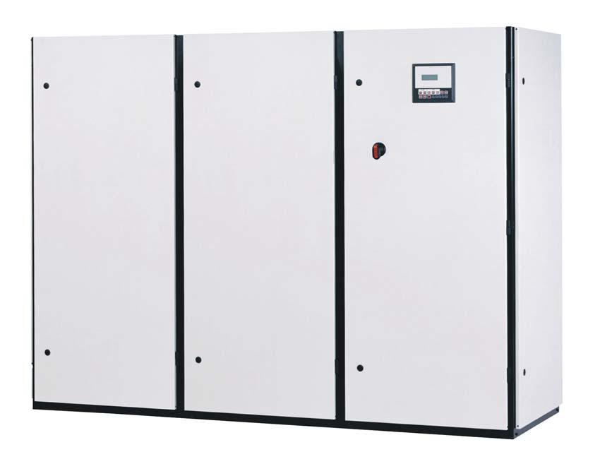
5 Overview The APC NetworkAIR CW computer room air conditioning system provides precise environmental control for present and future conditioned spaces. Precision environmental requirements now reach far beyond the confines of the traditional data center or computer room to encompass a larger suite of applications, referred to as technology rooms. Critical environment applications include: Computer rooms Telecommunication facilities Clean rooms Power equipment Medical equipment rooms Archives LAN/WAN environments A worldwide network of APC representatives is fully qualified to provide engineering, sales, installation and service for our products. APC warrants all parts for 12 months from shipment. Extended warranties are available. Capacity CW is available from kw (6-60 ton) in chilled water. Room Air Distribution Downflow systems discharge air into the raised floor plenum. These systems are suitable for areas with raised floors greater than 12" (305 mm) high. Return air is drawn in through the top of the system. Upflow systems discharge air into either a plenum or ductwork. These systems are suitable for areas without raised floors, as well as areas with raised floors. Air is drawn in through the front on the standard design or optionally from the rear of the system. Configuration Chilled Water Compliance Approval ETL/CETL UL Listed to UL 1995 and CSA C22.2 No. 236 MEA# E (20-27kW), MEA# E (41-210kW) C US Standard Features Centrifugal Blower Assembly Heavy Gauge Steel Frame Main Power Circuit Breaker Microprocessor Controller 2 or 3 Way Modulating Valve Front Service Access Only Optional Features Pure Steam Canister Humidifier 30% ASHRAE 52.1 Filters Three Phase Electric Reheat Plenums (with or without grilles) Floorstand (with or without turning vane, seismic) Discharge Duct Collar Downflow Return Duct Casters Environmental Monitoring ModBus/JBus Gateway High Efficiency Filters 1 Prefilters Spot or Cable Water Detector(s) Firestat Smoke Detector Condensate Pump Remote Relay Shutdown Reheat/Humidity Lockout Remote Display and/or Sensor Redundant Group Control Hot Water/ Steam Reheat 3-Way Valve Flowswitch Optional HP Motors Custom Alarm Contacts APC NetworkAIR CW 1
6 Standard Features Cabinet The frame is constructed of heavy gauge steel for maximum strength. Steel access panels are insulated for quieter operation. The unit has been designed for full service access from the front. The flush mounted panels are removable using convenient quarter-turn fasteners. The access doors for the electronic controller and electrical panel can be opened without interrupting the operation of the unit. Cooling Coil/Drain Pan The advanced prism arrangement of cross-circuited cooling coils connected to the incoming chilled water supply provides greater sensitivity in cooling and dehumidification. Designed for high sensible heat ratios, the coil is constructed with copper tubes, aluminum fins, galvanized steel end plates, and includes a stainless steel condensate pan. The return is drawn evenly through the entire face of the cooling coil. Electrical Panel The electrical panel contains the contactors, starters, overload protection devices, and input power disconnects. Each wire (except jumpers) is numbered every 3 (80mm), or color coded to facilitate circuit tracing when installing and servicing the unit. Each AC power circuit is individually branch circuit fused on all three phases. All motor devices are thermally and short circuit protected. The electrical panel is easily accessible from the front of the unit. An emergency cool override switch can be manually activated to initiate cooling and a field wired thermostat can be utilized to control cooling operation. All electrical components are ULlisted and -recognized and all wiring conforms to NFPA 70 (NEC) and UL 1995 requirements. Main Power Disconnect A nonautomatic main power circuit breaker disconnects all high voltage power to the unit if necessary. The disconnect switch is accessible without removing the electric box cover. Fan/Motor Section The NetworkAIR CW includes multiple centrifugal blower assemblies that have been engineered for quiet, reliable operation. Lower blower speeds reduce noise and extend belt and bearing life. Permanently lubricated bearings, a variable pitch drive, and an adjustable motor base all ensure dependable operation. In addition, the return air is evenly distributed across the cooling coil. Chilled Water Modulating Valve A fully modulating two-way or three-way valve is microprocessor controlled to automatically direct the proper amount of chilled water into the cooling coil to maintain desired conditions. The pressure rating of the valve is 400 psi (2700kPa). 2 APC NetworkAIR CW
7 Optional Features Air Filter The filtration of conditioned air is extremely vital to maintaining the clean, particle-free environment required by electrical equipment. The system uses 30% efficient (100 microns) (ASHRAE ), 4 (102 mm) deep filters, with full depth filter pleats. Deeper filters produce a lower pressure drop, requiring less energy during normal operation. Filters are replaceable through the front of the upflow unit, through the top of the downflow unit, and from either side of the filter box on the back of the upflow rear return unit. Humidifier The humidifier utilizes a pure steam generator specifically designed for hi-tech area environmental control. The pure steam eliminates contaminating mineral deposits, bacteria, white dust and excessive humidity. The humidifier requires little or no scheduled maintenance. Automatic flushing combined with an indicator that signals when the canister is to be changed, ensure maintenance free operation. Electric Reheat A three-phase electrical resistance heater sized to offset the sensible cooling capacity in the dehumidification mode is incorporated in each NetworkAIR CW. The reheat elements are low watt density sheathed components. The reheat is three phase to provide even phase loading. Reheat elements are electrically and thermally protected. One stage is standard on 20-27kW models, with a maximum of two stages available. Two stages come standard on kW models, with a maximum of three stages available. Discharge Duct Collar A 1 (25 mm) duct flange ships loose from the factory for field installation to provide convenient connection to external ductwork for either supply or return as needed. Spot Water Detector(s) The solid-state spot water detector activates an audible alarm on the controller when moisture is detected. Cable Water Detector A 50 leak detection cable is placed on the floor around all possible leak sources. If water or other liquids contact the cable anywhere along its length, an alarm is triggered. Firestat A firestat is available for factory installation in the air stream of the unit. If the return air temperature reaches 125 F (52 C), an audible and visual alarm on the microprocessor will be activated and the unit will immediately shutdown. Smoke Detector The factory-installed smoke detector is designed to sense smoke in the return air stream. Upon detection of smoke, an audible and visual alarm on the microprocessor will be activated and the unit will be immediately shutdown. Condensate Pump The factory-installed and wired condensate pump will pump 252 gal/h (0.26 L/s) at 20 ft. (6.1 m) head. Remote Relay Shutdown Shutdown of the NetworkAIR system can be done remotely by a factory installed relay. The relay can be ordered with a 24V, 120V, or 240V coil. Reheat/Humidity Lockout Lockout prevents operation of electrical loads not essential for continued site operation when facilities have limited backup power capacity. Redundant Group Control Allows up to six NetworkAIR units ability to communicate with each other to automatically switch upon alarm condition, or timed rotation. Can also allow standby units the ability to assist the running system. Remote Display Panel The microprocessor controller allows facility or building maintenance personnel to evaluate and control the unit from up to 50ft. away from the unit, without having to enter the secured space. Remote Sensor(s) Environmental sensor(s) can be strategically placed, up to 50ft. from the unit to better meet the site s cooling needs. The sensor must be positioned to permit air movement across the sensors. Hot Water Reheat (Modulating) A modulating control valve controls hot water reheat. The system is supplied with a factory-installed copper tube and an aluminum fin hot water coil. Steam/Hot Water Reheat (2-Way On/Off) An on/off solenoid valve maintains the dry bulb temperature when the system is in dehumidification and reheat mode. Completely factory pre-piped, the system includes a copper tube, aluminum fin reheat coil, float, and thermostatic steam trap. APC NetworkAIR CW 3
8 Optional Features Optional Blower/Motor HP An optional HP motor can be used for increased CFM or to accommodate special air filters, high external static pressure, etc. while maintaining the standard CFM rating (N/A on 105kW (30 ton) systems). High Efficiency Filter(s) Pleated final filters with efficiencies of 45% or 65%, 4 (102mm) deep, allow for the removal of a greater percentage of airborne particulate contaminates. Prefilter(s) Prefilters capture large airborne particulate contaminates, thereby extending the life of the high-efficiency filter. Prefilters are 1 (25mm) deep and easily disposed. 3-Way Valve Flow Switch A Single-Pole, Double-Throw flow switch can be wired to energize one device and de-energize another device powered from the same source when fluid flow either exceeds or drops below the set flow rate. Plenum Air discharge plenums are available with upflow configurations. Heights are offered in 20 (508mm) and 24 (610mm). Manually adjustable, double deflecting grilles are provided on 3 or 4 sides. Air Deflector A field installed air deflector runs the length of the unit and attaches to the floorstand for changing air direction from vertical to horizontal. Floorstand The floorstand raises the unit above the subfloor to match the height of the raised floor. Heights are available (from 6 (142 mm) to 36 (914 mm)) in 3 (76 mm) increments and are adjustable +/- 1.5 (38.1 mm). APC recommends at least 12 (305 mm) high floorstands for their downflow units. Adjustment is provided by threaded pedestals. Vibration absorbing pads are included. The floorstand, pedestal, and pads ship loose. In areas where earthquakes are a concern, seismic floorstands are available in 12 (305mm), 18 (457 mm) and 24 (610 mm) heights. Casters A set of 6 plated rolling caster wheels are available for handling of equipment. Environmental Monitoring Unit A stand-alone unit performs contact monitoring and continuous temperature and humidity sensing through two probes (one included). The unit is controlled by available web, control console, or SNMP interface with a network connection. In the event of an environmental anomaly, notification is sent via or SNMP. The unit is x 9 x 2.75 (464mm x 229mm x 70mm). The probes extend up to 12 (3.66m) from the unit. Environmental Management System A browser-accessible, 1U, rackmountable appliance allows monitoring of environmental conditions. Monitoring of one temperature, one humidity, and one vibration sensor ship standard. When conditions change, notifications are sent via to appropriate personnel. The EMS provides 8 input contacts, 2 output relays, and controllable power outlets for defining actions remotely should conditions warrant it. ModBus/JBus Gateway The Gateway translates transmission protocol from the system s network into ModBus/JBus communication protocol. One gateway can support up to 16 units. Custom Alarm Contact Closures Each unit is equipped with dry contact closures. Upon activation of the associated alarm, a discreet Normally open or Normally closed contact is available for remote monitoring of that discrete alarm. Downflow Return Duct A return duct the length and width of the unit may be field installed on a downflow unit to provide convenient connection to external ductwork. 4 APC NetworkAIR CW
9 Microprocessor Controller Microprocessor Controller The microprocessor controller is standard on the main module of each system. The controller provides precision control for the demanding requirements of: Data centers Control rooms Clean rooms Switch rooms UPS rooms The easy-to-use display allows the operator to select options from the device s menu-driven interface to control and monitor the connected air conditioning system. Status Complete status monitoring is provided within the status menu of the microprocessor controller. Available information includes: Current Temperature/Humidity Temperature/Humidity Setpoint Cooling/Heating Status Humidification/Dehumidification Status Alarms Quick access to any alarm condition is facilitated through the menu structure. The alarm key acts as a hot key providing immediate access to the alarm display menu. Presence of a new alarm will sound the audible alarm. The red alarm LED on the display panel will remain illuminated until all alarms have been cleared. The temperature and humidity alarm setpoints are adjustable. Alarm annunciations include: Loss of airflow Clogged filter High head pressure Low suction pressure High/Low temperature High/Low humidity Automatic setpoint crossover protection will prevent the setting of the heat setpoint above the cool setpoint and the humidification setpoint above the dehumidification setpoint. Setpoint adjustment can be restricted to only operators with knowledge of the security codes set within the security menu structure. Configuration Flexibility is offered through the use of the configuration menu. Operating requirements are satisfied by changing the configuration settings. New configurations are stored in EEPROM and protected from unauthorized tampering by the four-digit security password, selected in the security menu. Configuration options include: Fahrenheit or celsius display Power loss restart time delay Redundant unit grouping Alarm input polarity Alarm enable Temperature/Humidity deadbands Small room delay Common Alarm Contact A common alarm relay is installed on every microprocessor. In the event of an alarm condition, the relay will change state. The user can select which alarms change the state of the relay. This feature allows for remote enunciation of alarm status. Run Times The major components within the unit have independent run timers that monitor and store accumulated run hours on the components. The run timers are provided with operator adjustable run time alarms. Security Multiple security levels prevent unauthorized adjustment of important system parameters. The user may select a four-digit password for setpoint and configuration changes. Should the password be forgotten, APC can provide temporary access. Monitoring Supervisory network communications card are available for interfacing with building management systems. Please check with APC for compatibility with your building management system. Cool Inhibit Prevents the unit from over-cooling during the dehumidification cycle. If the space temperature falls below a user adjustable setpoint, cooling will become inhibited until the space temperature returns to setpoint. Remote Shutdown Events external to the unit, such as activation of a fire suppression system may require the unit to shut down remotely. Additionally this feature may be tied into a BMS that would allow remote control of the units on/off status. APC NetworkAIR CW 5
10 Performance Specifications Chilled Water COOLING CAPACITY - BTU/ HR (kw) 45F (7.2C) -- EWT 20 kw (6 ton) 27 kw (8 ton) 41 kw (12 ton) 50 kw (15 ton) 70 kw (20 ton) 87 kw (25 ton) 105 kw (30 ton) 123 kw (35 ton) 140 kw (40 ton) 175 kw (50 ton) 210 kw (60 ton) 80F DB, 67F WB (26.7C DB, 19.4C WB) 50% RH Total-BTU/HR (kw) 70,000 (20.6) 112,000 (32.9) 176,000 (52.3) 207,000 (60.8) 254,000 (74.3) 306,000 (89.6) 351,000 (103.0) 443,000 (129.6) 502,000 (147.0) 610,000 (178.6) 697,000 (204.3) Sensible-BTU/HR (kw) 50,000 79, , , , , , , , , ,000 (14.6) (23.0) (37.3) (44.0) (51.3) (65.0) (73.3) (93.6) (103.6) (120.6) (140.3) Flow Rate-GPM (L/s) (0.9) (1.4) (2.2) (2.6) (3.2) (3.9) (4.5) (5.6) (6.4) (7.8) (8.9) Pressure Drop-psig (kpa) 11.2 (77.2) 19.9 (137.2) 21.4 (147.5) 21.8 (150.3) 18.0 (124.1) 19.9 (137.2) 19.7 (135.8) 22.3 (153.8) 28.4 (195.8) 27.6 (190.3) 35.5 (244.8) 75F DB, 62.5F WB (23.9C DB, 16.9C WB) 50% RH Total-BTU/HR (kw) 51,000 83, , , , , , , , , ,000 (14.9) (24.3) (37.3) (45.0) (55.3) (66.6) (77.3) (97.9) (111.3) (135.3) (155.6) Sensible-BTU/HR (kw) 43,000 69, , , , , , , , , ,000 (12.6) (20.3) (32.3) (38.6) (45.0) (57.3) (65.0) (83.0) (92.3) (106.6) (124.9) Flow Rate-GPM (L/s) 10.3 (0.6) 16.9 (1.1) 25.9 (1.6) 31.1 (2.0) 38.2 (2.4) 46.1 (2.9) 53.5 (3.4) 67.6 (4.3) 77.0 (4.9) 93.6 (5.9) (6.8) Pressure Drop-psig (kpa) (42.1) (77.9) (81.4) (84.8) (71.0) (77.2) (78.6) (90.3) (115.1) (112.4) (146.2) 75F DB, 61F WB (23.9C DB, 16.1C WB) 45% RH Total-BTU/HR (kw) 48,000 79, , , , , , , , , ,000 (14.0) (23.3) (35.6) (43.0) (52.3) (63.9) (74.0) (94.0) (106.3) (127.6) (147.6) Sensible-BTU/HR (kw) 45,000 (13.3) 73,000 (21.3) 115,000 (33.6) 138,000 (40.6) 161,000 (47.0) 205,000 (60.0) 234,000 (68.6) 298,000 (87.3) 331,000 (97.0) 379,000 (111.0) 446,000 (130.6) Flow Rate-GPM (L/s) (0.6) (1.0) (1.6) (1.9) (2.3) (2.8) (3.2) (4.1) (4.6) (5.6) (6.4) Pressure Drop-psig (kpa) (37.9) (70.3) (73.8) (77.9) (63.4) (71.0) (73.1) (83.4) (106.2) (100.0) (131.7) 72F DB, 60F WB (22.2C DB, 15.5C WB) 50% RH Total-BTU/HR (kw) 42,000 (12.3) 70,000 (20.6) 108,000 (31.6) 130,000 (38.3) 160,000 (46.9) 194,000 (56.6) 226,000 (66.3) 286,000 (83.9) 325,000 (95.3) 393,000 (115.3) 455,000 (133.3) Sensible-BTU/HR (kw) 39,000 64, , , , , , , , , ,000 (11.6) (18.6) (29.6) (35.3) (41.3) (52.6) (60.0) (76.6) (85.3) (98.3) (115.6) Flow Rate-GPM (L/s) (0.5) (0.9) (1.4) (1.7) (2.0) (2.5) (2.9) (3.7) (4.2) (5.0) (5.8) Pressure Drop-psig (kpa) 4.3 (29.6) 8.2 (56.5) 8.5 (58.6) 9.1 (62.7) 7.5 (51.7) 8.3 (57.2) 8.5 (58.6) 9.7 (66.9) 12.4 (85.5) 12.1 (83.4) 15.8 (108.9) 72F DB, 58.6 WB (22.2D DB, 14.8C WB) 45% RH Total-BTU/HR (kw) 41,000 62, , , , , , , , , ,000 (12.0) (18.0) (30.3) (36.6) (45.6) (54.6) (63.3) (79.6) (93.6) (111.6) (129.6) Sensible-BTU/HR (kw) 40,000 62, , , , , , , , , ,000 (11.9) (18.0) (30.0) (36.3) (43.6) (54.3) (62.3) (78.6) (89.9) (103.6) (122.0) Flow Rate-GPM (L/s) 8.2 (0.5) 12.6 (0.8) 20.9 (1.3) 25.4 (1.6) 31.5 (2.0) 37.8 (2.4) 43.8 (2.8) 55.1 (3.5) 64.7 (4.1) 77.1 (4.9) 89.6 (5.7) Pressure Drop-psig (kpa) (26.9) (44.1) (54.5) (57.9) (49.0) (53.1) (54.5) (60.7) (82.7) (77.9) (103.4) 70F DB, 58.5F WB (21.1C DB, 14.8C WB) 50% RH Total-BTU/HR (kw) 38,000 63,000 97, , , , , , , , ,000 (11.3) (18.3) (28.3) (34.3) (42.0) (50.9) (60.0) (76.0) (86.6) (104.3) (120.9) Sensible-BTU/HR (kw) 36,000 (10.6) 59,000 (17.3) 93,000 (27.3) 112,000 (32.9) 132,000 (38.6) 166,000 (48.6) 192,000 (56.3) 245,000 (71.6) 274,000 (80.3) 316,000 (92.6) 371,000 (108.9) Flow Rate-GPM (L/s) (0.5) (0.8) (1.2) (1.5) (1.8) (2.2) (2.6) (3.3) (3.8) (4.6) (5.3) Pressure Drop-psig (kpa) (24.1) (45.5) (47.6) (51.0) (42.1) (46.2) (49.0) (55.8) (71.0) (68.9) (91.0) 70F DB, 57.2F WB (21.1C DB, 14.0C WB) 45% RH Total-BTU/HR (kw) 36,000 (10.6) 56,000 (16.3) 92,000 (27.0) 112,000 (32.9) 137,000 (40.3) 165,000 (48.3) 198,000 (57.9) 243,000 (71.3) 281,000 (82.3) 332,000 (97.3) 388,000 (113.6) Sensible-BTU/HR (kw) 36,000 56,000 92, , , , , , , , ,000 (10.6) (16.3) (27.0) (32.9) (39.6) (48.3) (57.6) (71.3) (81.6) (94.9) (111.9) Flow Rate-GPM (L/s) (0.5) (0.7) (1.2) (1.4) (1.7) (2.2) (2.5) (3.2) (3.6) (4.3) (5.0) Pressure Drop-psig (kpa) 3.2 (22.1) 5.2 (35.9) 6.5 (44.8) 6.9 (47.6) 5.6 (38.6) 6.3 (43.4) 6.6 (45.5) 7.4 (51.0) 9.4 (64.8) 8.8 (60.7) 11.7 (80.7) AIR SYSTEM -- BELT DRIVE CENTRIFUGAL Air Volume-CFM (L/s) 1,800 (857) 2,800 (1,333) 5,250 (2,480) 5,900 (2,780) 6,200 (2,930) 8,900 (4,200) 9,400 (4,440) 12,200 (5,760) 12,800 (6,040) 13,800 (6,510) 16,500 (7,790) Blower Motor-HP (kw) (9.56) (0.8) (1.5) (2.2) (2.2) (3.7) (5.6) (5.6) (5.6) (7.5) (7.5) External Static Pressureinches of water (Pa) 0.3 (75) 0.3 (75) 0.3 (75) 0.3 (75) 0.3 (75) 0.3 (75) 0.3 (75) 0.3 (75) 0.3 (75) 0.3 (75) 0.3 (75) Number of Blowers APC NetworkAIR CW
11 Performance Specifications Chilled Water Performance Specifications - Chilled Water CW (kw-tons) 20 kw 27 kw 41 kw 50 kw 70 kw 87 kw 105 kw 123 kw 140 kw 175 kw 210 kw (6 ton) (8 ton) (12 ton) (15 ton) (20 ton) (25 ton) (30 ton) (35 ton) (40 ton) (50 ton) (60 ton) CHILLED WATER CONTROL VALVE Size-2-Way CW Valve-- Inches, NPT (Cv)* 3/4 (7.5) 1 (14) 1 (14) 1 (14) 1-1/4 (20) 1-1/4 (20) 1-1/2 (28) 1-1/2 (28) 1-1/2 (28) 2 (41) 2 (41) Size-3-Way CW Valve-- Inches, NPT (Cv)* 3/4 (7.5) 1 (14) 1 (14) 1 (14) 1-1/4 (20) 1-1/4 (20) 1-1/2 (28) 1-1/2 (28) 1-1/2 (28) 2 (41) 2 (41) COOLING COIL -- A FRAME Face Area-ft 2 (m ) (0.63) (0.63) (1.62) (1.62) (1.62) (1.87) (1.87) (2.74) (2.74) (3.55) (3.55) Rows Deep Face Velocity-FPM (m/s) (1.34) (2.09) (1.53) (1.65) (1.75) (2.18) (2.30) (2.05) (2.15) (1.83) (2.15) HUMIDIFICATION --- SOLID STATE ELECTRODE CANISTER Flush Cycle automatic automatic automatic automatic automatic automatic automatic automatic automatic automatic automatic Capacity-Lbs/hr (Kg/hr) 5 (2.3) 5 (2.3) 17 (7.7) 17 (7.7) 17 (7.7) 17 (7.7) 17 (7.7) 17 (7.7) 17 (7.7) 17 (7.7) 17 (7.7) kw FILTERS Quantity x x x x x x x x x x x 25 Size -- Inches (mm) (406 x711) (406 x711) 16 x x x x x x 20 (406 x635) (406 x635) (406 x635) (406 x635) (406 x635) (406 x635) (406 x635) (406 x635) (406 x635) (406 x508) (406 x508) (406 x508) (406 x508) (406 x508) (406 x508) Depth -- Inches (mm) (102) (102) (102) (102) (102) (102) (102) (102) (102) (102) (102) REHEAT Electric -- Equally Loaded Three (3) Phase, Finned Tubular, Low-Watt Density Capacity -BTU/HR (kw) Includes Motor Heat** 27,000 (7.6) 29,000 (7.9) 57,000 (16.9) 61,000 (17.6) 61,000 (17.6) 92,000 (26.9) 99,000 (29.0) 99,000 (29.0) 99,000 (29.0) 132,000 (38.6) 132,000 (38.6) Stages Hot Water F (82.2C) EWT, 160F (71.1C) LWT Capacity-BTU/HR (kw) Includes Motor Heat 37,000 (10.9) 70,000 (20.6) 117,000 (34.3) 127,000 (37.3) 132,000 (38.9) 180,000 (52.6) 187,000 (54.9) 256,000 (75.1) 266,000 (77.9) 211,000 (61.6) 234,000 (68.6) GPM (L/s) (0.05) (0.13) (0.74) (0.80) (0.83) (1.12) (1.17) (1.60) (1.65) (1.31) (1.43) Pressure Drop-PSI (kpa) 0.2 (1.3) 0.7 (4.7) 0.6 (4.5) 0.7 (5.1) 0.8 (5.4) 1.2 (8.4) 1.3 (9.0) 2.8 (19.4) 2.9 (20.3) 4.5 (30.8) 5.3 (36.8) Control Valve solenoid solenoid solenoid solenoid solenoid solenoid solenoid solenoid solenoid solenoid solenoid Steam psig (103.3 kpa) Capacity-BTU/HR (kw) Includes Motor Heat 75,000 (21.9) 97,000 (29.0) 104,000 (30.3) 117,000 (34.0) 118,000 (34.6) 191,000 (55.9) 209,000 (61.0) 235,000 (68.9) 247,000 (72.3) 292,000 (85.6) 346,000 (101.0) Control Valve solenoid solenoid solenoid solenoid solenoid solenoid solenoid solenoid solenoid solenoid solenoid PHYSICAL DATA Weight -- lbs (kg) (325) (325) (390) (445) (535) (570) (640) (710) (800) (870) (960) Height -- Inches (mm) (1,930) (1,930) (1,829) (1,829) (1,829) (1,829) (1,829) (1,829) (1,829) (1,930) (1,930) Length -- Inches (mm) (889) (889) (1,572) (1,572) (1,572) (1,877) (1,877) (2,486) (2,486) (3,096) (3,096) Depth -- Inches (mm) (864) (864) (886) (886) CONNECTION SIZES*** Water In/Out -- Inches OD 7/8 7/8 1-3/8 1-3/8 1-3/8 1-5/8 1-5/8 1-5/8 1-5/8 2-1/8 2-1/8 Hot Water Supply Line -- Inches OD 5/8 5/8 5/8 5/8 7/8 7/8 7/8 7/8 7/8 7/8 7/8 Return Line -- Inches OD 5/8 5/8 5/8 5/8 7/8 7/8 7/8 7/8 7/8 7/8 7/8 Steam Supply Line -- Inches OD 5/8 5/8 5/8 5/8 5/8 5/8 5/8 5/8 7/8 7/8 7/8 Humidifier Supply Line -- Inches OD 1/4 1/4 1/4 1/4 1/4 1/4 1/4 1/4 1/4 1/4 1/4 Condensate Drain Return Line -- Inches ID 7/8 7/8 7/8 7/8 7/8 7/8 7/8 7/8 7/8 7/8 7/8 *2-Way Single Seated, 400 psig W.W.P. max **With equal loading on each phase, rated at V / 3-phase, 480V / 3-phase and 600V / 3-phase ***Connections sizes, not recommended piping sizes (886) (886) (886) (886) (886) (886) (886) APC NetworkAIR CW 7
12 Electrical Data CHILLED WATER - Standard HP REHEAT Electric Steam, Hot Water or None Electric Steam, Hot Water or None HUMIDIFIER Electrode Canister - Steam Electrode Canister - Steam Steam or None Steam or None VOLTAGE kw (6 ton) FLA WSA MOP kw (8 ton) FLA WSA MOP kw (12 ton) FLA WSA MOP kw (15 ton) FLA WSA MOP kw (20 ton) FLA WSA MOP kw (25 ton) FLA WSA MOP kw (30 ton) FLA WSA MOP kw (35 ton) FLA WSA MOP kw (40 ton) FLA WSA MOP kw (50 ton) FLA WSA MOP kw (60 ton) FLA WSA MOP FLA = Full Load Amps WSA = Wire Size Amps MOP = Maximum Overcurrent Protection 8 APC NetworkAIR CW
13 Electrical Data CHILLED WATER - Optional HP REHEAT Electric Steam, Hot Water or None Electric Steam, Hot Water or None HUMIDIFIER Electrode Canister - Steam Electrode Canister - Steam Steam or None Steam or None VOLTAGE kw (6 ton) FLA WSA MOP kw (8 ton) FLA WSA MOP kw (12 ton) FLA WSA MOP kw (15 ton) FLA WSA MOP kw (20 ton) FLA WSA MOP kw (25 ton) FLA WSA MOP kw (30 ton) FLA N/A N/A N/A N/A N/A N/A N/A N/A N/A N/A N/A N/A N/A N/A N/A N/A WSA N/A N/A N/A N/A N/A N/A N/A N/A N/A N/A N/A N/A N/A N/A N/A N/A MOP N/A N/A N/A N/A N/A N/A N/A N/A N/A N/A N/A N/A N/A N/A N/A N/A 123 kw (35 ton) FLA WSA MOP kw (40 ton) FLA WSA MOP kw (50 ton) FLA WSA MOP kw (60 ton) FLA WSA MOP FLA = Full Load Amps WSA = Wire Size Amps MOP = Maximum Overcurrent Protection APC NetworkAIR CW 9
14 Dimensional Data Downflow kW (6-8 ton) * All dimensions are in inches (mm). 10 APC NetworkAIR CW
15 Dimensional Data Downflow kW (12-20 ton) * All dimensions are in inches (mm). APC NetworkAIR CW 11
16 Dimensional Data Downflow kW (25-30 ton) * All dimensions are in inches (mm). 12 APC NetworkAIR CW
17 Dimensional Data Downflow kW (35-40 ton) * All dimensions are in inches (mm). APC NetworkAIR CW 13
18 Dimensional Data Downflow kW (50-60 ton) * All dimensions are in inches (mm). 14 APC NetworkAIR CW
19 Dimensional Data Upflow kW (6-8 ton) * All dimensions are in inches (mm). APC NetworkAIR CW 15
20 Dimensional Data Upflow kW (12-20 ton) * All dimensions are in inches (mm). 16 APC NetworkAIR CW
21 Dimensional Data Upflow kW (25-30 ton) * All dimensions are in inches (mm). APC NetworkAIR CW 17
22 Dimensional Data Upflow kW (35-40 ton) * All dimensions are in inches (mm). 18 APC NetworkAIR CW
23 Dimensional Data Upflow kW (50-60 ton) * All dimensions are in inches (mm). APC NetworkAIR CW 19
24 Dimensional Data Upflow, Rear Return kW (6-8 ton) * All dimensions are in inches (mm). 20 APC NetworkAIR CW
25 Dimensional Data Upflow, Rear Return kW (12-20 ton) * All dimensions are in inches (mm). APC NetworkAIR CW 21
26 Dimensional Data Upflow, Rear Return kW (25-30 ton) * All dimensions are in inches (mm). 22 APC NetworkAIR CW
27 Dimensional Data Upflow, Rear Return kW (35-40 ton) * All dimensions are in inches (mm). APC NetworkAIR CW 23
28 Dimensional Data Floorstand kW (6-8 ton) Floorstand kW (12-20 ton) 24 APC NetworkAIR CW
29 Dimensional Data Floorstand kW (25-30 ton) Floorstand kW (35-40 ton) APC NetworkAIR CW 25
30 Dimensional Data Floorstand kW (50-60 ton) Top Discharge Plenum kW (6-8 ton) 26 APC NetworkAIR CW
31 Dimensional Data Top Discharge Plenum kW (12-20 ton) Top Discharge Plenum kW (25-30 ton) APC NetworkAIR CW 27
32 Dimensional Data Top Discharge Plenum kW (35-40 ton) Top Discharge Plenum kW (50-60 ton) 28 APC NetworkAIR CW
33 Guide Specifications PART 1 PART 1 GENERAL 1.01 SUMMARY A. The environmental control system shall automatically monitor and control heating, cooling, humidifying, dehumidifying, and filtering functions for the conditioned space. The system shall be built to the highest quality engineering and manufacturing standards, and shall be floor mounted and configured for (up/down) discharge of conditioned airflow DESIGN REQUIREMENTS A. The system shall be as described in the following specification as manufactured by APC. 1. Model:. 2. Total cooling capacity: MBH (kw). 3. Sensible cooling capacity: MBH (kw). 4. Return air temperature: º F (º C) DB. 5. Return air temperature: º F (º C) WB. 6. Entering chilled water: º F (º C). 7. Leaving chilled water: º F (º C). 8. Humidity: % RH. 9. Air quantity: CFM (L/s). 10. External Static Pressure inches (Pa). 11. Humidifier capacity: lbs/hr (kg/hr). 12. Electrical supply: V, ph, 60 Hz SUBMITTALS A. Submittals shall be provided with the proposal and shall include: capacity data, electrical data, physical data, electrical connection drawing, and piping connection drawing QUALITY ASSURANCE A. The system shall be completely factory-tested prior to shipment. Testing shall include, but not be limited to: complete pressure and leak testing to ensure system integrity, Hi-Pot test, and controls calibration and settings. Each system shall ship with a completed test report to verify completion of factory testing procedure. The system shall be NTRL listed, MCA, and electrical system shall be UL Listed to UL 1995 and CSA 22.2 No WARRANTY A. System parts shall be warranted for a period of 12 months from date of shipment from factory. APC NetworkAIR CW 29
34 Guide Specifications PART 2 PART 2 PRODUCT 2.01 STANDARD COMPONENTS A. MICROPROCESSOR 1. The microprocessor controller shall provide total environmental control. The system, based on the main controller, shall offer up to eight analog inputs, two analog outputs, twelve digital inputs and thirteen digital outputs. The operator interface shall provide a 4- line, 80-character backlit LCD display. User-friendly menu structure along with clearly defined prompts shall allow the operator to easily move about the program and monitor the following functions and alarm conditions. a. Status: Complete status monitoring shall be provided within the status menu of the microprocessor controller, and shall include the following information: current temperature, current humidity, temperature setpoint, humidity setpoint, cooling status, heating status, humidification status and dehumidification status. b. Alarms: Quick access to any alarm condition shall be facilitated through the menu structure. Presence of a new alarm shall sound an audible alarm. A red alarm LED on the display panel shall remain illuminated until such time that all alarms have been cleared. Alarm annunciation shall include: loss of airflow, clogged filter, high head pressure, low suction pressure, high temperature, low temperature, high humidity, and low humidity. The temperature and humidity alarm setpoints are user adjustable. c. Setpoint: The microprocessor controller shall provide independent setpoints for heating, cooling, humidification, and dehumidification. Automatic setpoint cross-over protection shall prevent the setting of the heat setpoint above the cool setpoint and the humidify setpoint above the dehumidify setpoint. Setpoint adjustment shall be capable of being protected via security code. d. Configuration: Flexibility shall be offered through the use of the configuration menu. It shall closely match the operating requirements by changing the configuration settings. The site configuration shall be stored in the EEPROM and be protected from unauthorized tampering by the user selectable 4-digit security password in the security menu. Configuration options shall include: Fahrenheit or Celsius display, power-loss restart time-delay, primary-secondary transfer functions, alarm input polarity, alarm enable, temperature deadbands, humidity deadbands, and small room delay. e. Run time: The major components within the unit shall have independent run-timers that monitor and store the accumulated run-hours on the components. The run timers shall be provided with operator-adjustable run-time alarms for proper component maintenance. f. Security: The microprocessor shall have multiple security levels to prevent unauthorized adjustment of the important system parameters. A user-selectable 4-digit password shall allow setpoint and configuration changes. 30 APC NetworkAIR CW
35 Guide Specifications B. CABINET CONSTRUCTION 1. The cabinet and frame shall be constructed from welded structural steel. Access panels shall be flush with the frame and insulated with fiberglass 1 in. (25 mm) in thickness, 1.5 lb/ft 3 (24.0 kg/m 3 ) in density. The panels shall be powder coated and lift off for access to the unit. A piping and electrical access plate shall be provided in the bottom of the unit. All units shall require front service access, 24 in (610 mm) minimum. In addition, APC recommends 12 rear clearance on upflow units to accommodate for return grills at the back of the unit. C. FAN/MOTOR SECTION 1. The unit shall be configured for draw-through air pattern, to provide uniform air-flow over the entire face of the coil. The blower shall be double-inlet centrifugal type, with forwardcurving blades, dynamically and statically balanced. Each blower shall be independently driven by a high-efficiency motor. The drive package shall be designed for 200% of fan motor horsepower. The motor and blower shall be mounted on a common frame. The air distribution system for the 20-70kW (6-20 ton) units shall be comprised of a single blower. The kW (25-40 ton) units shall utilize 2 blowers and kW (50-60 ton) units shall be equipped with 3 blowers. Each blower shall be driven by a single motor with belt and pulley drive. D. MAIN POWER DISCONNECT 1. A non-automatic main power circuit breaker shall disconnect high voltage power to the unit if necessary. Disconnect switch shall be accessible without removing electric box cover. E. ELECTRICAL PANEL 1. The electrical system shall conform to National Electrical Code (NEC) requirements. The control voltage shall be 24 VAC, wired in accordance with NEC Class 1 requirements. The wire for the control circuit shall not be smaller than 18-gauge AWG. Each wire shall end with a service loop and be securely fastened by an approved method. Control wires more than 6 in. (150 mm) shall be color-coded or numbered every 3 in. (80 mm) for ease of service tracing. All electrically-actuated components shall be easily accessible from the front of the unit. EAch high voltage unit shall be individually protected on all three phases. Main power shall be connected to a circuit breaker mounted on the electrical panel. The compressor and motor shall have overload and short circuit protection. The electrical box shall include all components and controls required for system operation. AN emergency cool override manual switch shall be provided with provision for control using a field supplied thermostat. Incoming power is V, phase, 60 Hz. APC NetworkAIR CW 31
36 Guide Specifications F. COOLING COIL/DRAIN PAN 1. The cooling coil shall use the latest heat-transfer technology, raised lanced-aluminum fins and smooth copper tubes. Coil end-supports shall be galvanized steel. An insulated stainless steel drain pan for condensate shall be included. G. CHILLED WATER MODULATING VALVE 1. A fully modulating two-way or three-way valve shall be microprocessor controlled to automatically direct the proper amount of chilled water into the cooling coil. The standard valve pressure rating shall be 400 psi (2758 kpa) OPTIONAL COMPONENTS A. AIR FILTER 1. The air filters shall be 30% efficient per ASHRAE Standard , UL Class 2. The full 4 (102 mm) deep, pleated filters shall be replaceable from the front on upflow units and from the top on downflow units. B. HUMIDIFIER 1. Humidifier shall be self-contained steam-generating type, factory piped and wired, with disposable cylinder and automatic solid-state control circuit. Capacity: lb/h (g/s). C. ELECTRIC REHEAT 1. Reheat elements shall be low watt density, wired for three-phase, loaded equally on all three phases and shall be electrically and thermally protected by automatic and manual reset thermal cutouts. Reheat capacity shall be MBH, kw, controlled in # steps. D. DISCHARGE DUCT COLLAR 1. A 1 (25 mm) duct flange shall be provided for field installation on a unit to provide convenient connection to external ductwork. E. SPOT WATER DETECTOR 1. A water detector shall be factory-wired and shipped in the bottom of the unit to sense water and send a signal to the master control giving the operator possible alarm indications options for shutdown. The water detector shall be provided with 15 ft (5 m) of wire. 32 APC NetworkAIR CW
37 Guide Specifications F. CABLE WATER DETECTOR 1. A leak detection sensing cable shall be shipped loose with the unit. If water or other conductive liquids contact the cable anywhere along its length, the main controller visually and audibly annunciates the leak. 2. The detector shall be provided with 35ft (10.6 m) of cable. Cable may be cascaded up to 1000ft (305 m). G. FIRESTAT 1. A firestat shall be factory-installed in the return air to sense heat and send a signal to the main controller shutting down the unit and activating a visual and audible alarm. H. SMOKE DETECTOR 1. A smoke detector shall be factory-installed in the return air to sense concentrations of smoke and send a signal to the main controller shutting down the unit and activating a visual and audible alarm. I. CONDENSATE PUMP 1. The Condensate Pump shall be factory installed and wired and shall pump 252 gal/h (0.26 L/s) at 20 ft. (6.1 m) head. J. REMOTE RELAY SHUTDOWN 1. Remote shutdown of the system can be done by a factory installed relay with a 24V, 120V, or 240V coil. The relay must be powered by others to disable the cooling system. K. REHEAT/HUMIDITY LOCKOUT 1. When facilities have limited backup power capacity, this lockout shall prevent the operation of electrical loads that are not essential for continued site operation. L. REDUNDANT GROUP CONTROL 1. Up to six units shall have the ability to communicate with each other to automatically switch upon alarm condition, or time rotation. M. REMOTE DISPLAY PANEL 1. Facility and building-maintenance personnel shall have the ability to evaluate and control the unit from up to 50ft. from the unit. N. REMOTE SENSOR(S) 1. Environmental sensor(s) shall be strategically placed, up to 50ft from unit to better meet the site s cooling needs. It shall be positioned to permit air movement across the sensor. APC NetworkAIR CW 33
38 Guide Specifications O. HOT WATER REHEAT (MODULATING) 1. The unit shall be supplied with factory-installed copper tube, aluminum fin, and hot water reheat coil in place of electrical heater elements. Capacity shall be MBH (kw), with GPM (L/s) of º F (º C) entering hot water temperature. Hot water shall be controlled with a modulating control valve. P. STEAM/HOT WATER REHEAT (2-WAY ON/OFF) 1. The unit shall be supplied with a factory-installed copper tube, aluminum fin, reheats steam-coil in place of electrical heat elements. Capacity shall be MBH (kw) with 5 psi (35 kpa) of saturated steam. Steam shall be controlled by on/off solenoid valve. Q. OPTIONAL BLOWER/MOTOR HP 1. Optional motor shall be used for increased CFM or to accommodate special air filters, high external static pressure, etc. while maintaining standard CFM rating (N/A 150kW). R. HIGH EFFICIENCY FILTERS 1. Pleated final filter(s) with an efficiency of 45% and 65% per ASHRAE Standard The full 4 (102 mm) deep, pleated filters shall be replaceable from the front or top of the unit. S. PREFILTERS 1. Replaceable 1 (50 mm) deep, 30% efficient filters shall be installed upstream of the final filters to lengthen main filter life. T. 3-WAY VALVE FLOW SWITCH 1. A Single-Pole, Double-Throw flow switch shall be wired to energize one device and deenergize another device powered from the same source when fluid flow either exceeds or drops below the set flow rate. U. FLOORSTAND 1. The heavy gauge floorstand shall raise the unit above the subfloor to match the height of the raised floor. Heights shall be available from 6 (152mm) to 36 (915mm) on upflow units and 12" (305mm) to 36" (915mm) for downflow units, in 3" (76mm) increments and shall be adjustable +/- 1.5". Threaded pedestals shall provide adjustment. Vibration absorbing pads shall be included. Pedestals and vibration pads shall be included. Seismic floorstands shall be available in 12 (305mm), 18 (457mm), and 24 (610mm) heights. V. AIR DEFLECTOR 1. A ninety degree air deflector shall ship loose and shall be in. (mm) high. 34 APC NetworkAIR CW
39 Guide Specifications W. PLENUM 1. A discharge plenum shall mount on top of an upflow unit to direct and distribute conditioned air. a. The plenum shall be manually adjustable with double deflecting grilles provided on 3 or 4 sides. Plenum height shall be 20. b. The plenum shall be provided with a duct collar and no grilles. Plenum height shall be 24 (610mm). X. CASTERS 1. A set of 6 (152mm) plated rolling casters shall be provided for handling of equipment. Y. ENVIRONMENTAL MONITORING AND MANAGEMENT 1. Environmental Monitoring Unit: A stand-alone unit shall perform continuous temperature and humidity sensing through two available proves and contact monitoring. Unit shall be controlled by available web, control console, or SNMP interface with network connection. In the event of an environmental anomaly, notification shall be sent to the customer via e- mail or SNMP. The unit shall be x 9 x 2.75 (464mm x 229mm x 70mm). 2. Environmental Management System: A browser-accessible, 1U, rackmountable appliance shall allow monitoring of environmental conditions. Monitoring of one temperature, one humidity, and one vibration sensor shall ship standard. When conditions change, notifications shall be sent via to the appropriate personnel. The EMS shall provide eight input contacts, 2 output relays, and controllable power outlets for defining actions remotely should conditions warrant it. Z. CUSTOM ALARM DRY CONTACT CLOSURES 1. Each unit shall be equipped with any or all or the listed dry contact closures. Upon activation of the associated alarm, a discreet Normally Open or Normally Closed contact is available for remote monitoring of that discreet alarm. a. High Temperature Alarm b. Low Temperature Alarm c. High Humidity Alarm d. Low Humidity Alarm e. Clogged Filter Alarm f. Fire Alarm (with Firestat) g. Smoke Alarm (with Smoke Detector) h. Humidifier Change Canister Alarm i. Water Underfloor Alarm (with Water Detector) j. Condensate Pump Overflow Alarm (with Condensate Pump) k. Loss of Flow (with Flow Switch) APC NetworkAIR CW 35
Contents. APC NetworkAIR CW. CW 100 P=6 row 25 circuit C= Chilled Water BA= /3/60 E= Electric S= Steam Canister D= Downflow
 Contents Overview.............................................................. 1 Standard Features....................................................... 2 Optional Features.......................................................
Computer Room Air-Conditioning 60 Hz. Technical Data
 TM Computer Room Air-Conditioning 60 Hz 10 kw (3 tons) Technical Data Contents Overview.............................................................. 1 Standard Features.......................................................
Contents. APC NetworkAIR AFX AFX
 Contents Overview.............................................................. 1 Standard Features....................................................... 2 Optional Features.......................................................
Contents. APC NetworkAIR AFX AFX
 Contents Overview.............................................................. 1 Standard Features....................................................... 2 Optional Features.......................................................
Precision Air-Conditioning Units 60 Hz. Technical Data
 NetworkAIR Precision Air-Conditioning Units 60 Hz TM AFX Series Technical Data Contents Available Models................................. 1 Downflow 1 Upflow front-return 1 Upflow rear-return 1 Indoor
Precision Air-Conditioning Units 60 Hz. Technical Data
 â NetworkAIR TM CM Series Precision Air-Conditioning Units 60 Hz Technical Data Contents Available Models................................. 1 Spot-cooled 1 Ducted 1 System Configurations.............................
Data Aire Series Chilled Water 7 through 50 ton
 Data Aire Series Chilled Water 7 through 50 ton ISO 9001 Certified Data Aire the pioneer and builder of the most complete line of precision cooling equipment Data Aire s first precision cooling system
Computer Room Air-Conditioning 60 Hz. Technical Data
 TM Computer Room Air-Conditioning 60 Hz 35 150 kw (10 45 tons) Technical Data Contents Overview.............................................................. 1 Scalable Solution for Critical Environments.................................
Guide Specifications for InRow Direct Expansion
 Guide Specifications Guide Specifications for InRow Direct Expansion THIS GUIDE SPECIFICATION IS WRITTEN IN ACCORDANCE WITH THE CONSTRUCTION SPECIFICATIONS INSTITUTE (CSI) MASTERFORMAT. THIS SECTION MUST
Chilled Water 7 to 211 kw
 Chilled Water 7 to 211 kw Data Aire the pioneer and builder of the most complete line of precision cooling equipment Data Aire s first precision cooling system was developed by data processing facility
STULZ CyberAiR Floor Mounted Systems. Engineering Manual. Floor Mounted Air Conditioners
 Floor Mounted Air Conditioners Indoor Cooling Perimeter STULZ CyberAiR Floor Mounted Systems 60-730 kw Chilled Water Systems Precision Air Handlers Utilizing EC Fan Technology (60Hz Data) EM Engineering
Shelf Units R-407C. 2, 3, and 4 ton. ISO 9001 Certified
 Shelf Units 2, 3, and 4 ton R-407C ISO 9001 Certified the pioneer and builder of the most complete line of precision cooling equipment Data Aire s first precision cooling system was developed by data processing
Chilled Water 7 to 211 kw
 Chilled Water 7 to 211 kw Data Aire the pioneer and builder of the most complete line of precision cooling equipment Data Aire s first precision cooling system was developed by data processing facility
Modular Data Temp Systems Air Cooled Water/Glycol Cooled 8, 10 and 13 ton capacities R-410A. ISO 9001 Certified
 Modular Data Temp Systems Air Cooled Water/Glycol Cooled 8, 10 and 13 ton capacities ISO 9001 Certified the pioneer and builder of the most complete line of precision cooling equipment Back in the late
Data Aire LCS TM (Large Ceiling System) R-407C. 6, 8, 10, and 13 ton. ISO 9001 Certified
 R-407C. 6, 8, 10, and 13 ton. ISO 9001 Certified") Data Aire LCS TM (Large Ceiling System) 6, 8, 10, and 13 ton ISO 9001 Certified LCS TM (LARGE CEILING SYSTEMS) with refrigerant Product Description Performance and Electrical Data Dimensional Data Guide
Data Aire LCS TM (Large Ceiling System) 6, 8, 10, and 13 ton ISO 9001 Certified LCS TM (LARGE CEILING SYSTEMS) with refrigerant Product Description Performance and Electrical Data Dimensional Data Guide
Computer Room Air-Conditioning 60 Hz. Technical Data
 TM Computer Room Air-Conditioning 60 Hz Technical Data Contents Overview.............................................................. 1 Scalable Solution for Critical Environments.................................
Data Aire Mini Ceiling Systems 1, 1.5, 2, and 2.5 ton capacities R-410A. ISO 9001 Certified
 Data Aire Mini Ceiling Systems 1, 1.5, 2, and 2.5 ton capacities R-410A ISO 9001 Certified Data Aire the pioneer and builder of the most complete line of precision cooling equipment Data Aire s first
Guide Specifications PART 1 GENERAL 1.01 SUMMARY
 Guide Specifications PART 1 GENERAL 1.01 SUMMARY A The environmental control system shall be designed specifically for precision temperature control applications. It will automatically monitor and control
Series 6. Guide Specification 60 Hz. MISSION CRITICAL Air Conditioning Systems. ClimateWorx International Inc.
 MISSION CRITICAL Air Conditioning Systems Series 6 Guide Specification 60 Hz S6-GS-602017.doc ClimateWorx International Inc. 14 Chelsea Lane, Brampton, Ontario, Canada L6T 3Y4 Series 6 Guide Specification-60
Data Aire Mini Ceiling Systems 1, 1.5, 2, and 2.5 ton capacities R-410A. ISO 9001 Certified
 Data Aire Mini Ceiling Systems 1, 1.5, 2, and 2.5 ton capacities R-410A ISO 9001 Certified Data Aire the pioneer and builder of the most complete line of precision cooling equipment Data Aire s first
Data Aire LCS TM (Large Ceiling System) R-410A. 6, 8, 10, and 13 ton. ISO 9001 Certified
 R-410A. 6, 8, 10, and 13 ton. ISO 9001 Certified") Data Aire LCS TM (Large Ceiling System) 6, 8, 10, and 13 ton ISO 9001 Certified LCS TM (LARGE CEILING SYSTEMS) DX Product Description Performance and Electrical Data 3 the pioneer and builder of the most
Data Aire LCS TM (Large Ceiling System) 6, 8, 10, and 13 ton ISO 9001 Certified LCS TM (LARGE CEILING SYSTEMS) DX Product Description Performance and Electrical Data 3 the pioneer and builder of the most
Series 8. Guide Specification 60 Hz. MISSION CRITICAL Air Conditioning Systems. ClimateWorx International Inc.
 MISSION CRITICAL Air Conditioning Systems Series 8 Guide Specification 60 Hz S8-GS-602017.doc 2014 ClimateWorx International Inc. 14 Chelsea Lane, Brampton, Ontario, Canada L6T 3Y4 Series 8 Guide Specification-60
Data Aire Series Air Cooled, Water/Glycol Cooled 6 through 30 Ton Dual Circuits R-407C
 Data Aire Series Air Cooled, Water/Glycol Cooled 6 through 30 Ton Dual Circuits R-407C 1 Data Aire the pioneer and builder of the most complete line of precision cooling equipment Data Aire s first precision
Liebert. Deluxe System/3 Chilled Water Systems ENVIRONMENTAL CONTROL TECHNICAL DATA MANUAL. 50 Hz and 60 Hz ISO 9000 CERTIFIED COMPANY
 Liebert Keeping Business in Business ENVIRONMENTAL CONTROL Deluxe System/3 Chilled Water Systems TECHNICAL DATA MANUAL 50 Hz and 60 Hz ISO 9000 CERTIFIED COMPANY Table of Contents Liebert Technology and
CeilMate TM Series 3 and 4 tons of cooling capacity. Ceiling Mounted Systems. Air Handler with Remote Condensing Unit Air Handler designed for R-410A
 A e r o S y s I n c o r p o r a t e d Ceiling Mounted Systems CeilMate TM Series 3 and 4 tons of cooling capacity Air Handler with Remote Condensing Unit Air Handler designed for R-410A AeroSys, Inc. 929
Mini-Space EC DX and CW 4 12 kw Systems Vertical Floor Mounted, 60 Hz Data
 Mini-Space EC DX and CW 4 12 kw Systems Vertical Floor Mounted, 60 Hz Data Engineering Manual ABOUT STULZ STULZ is a privately owned, global manufacturer of highly efficient temperature and humidity management
Modular Data Temp Systems Air Cooled Water/Glycol Cooled R-407C. 8, 10 and 13 ton capacities. ISO 9001 Certified
 Modular Data Temp Systems Air Cooled Water/Glycol Cooled 8, 10 and 13 ton capacities R-407C ISO 9001 Certified the pioneer and builder of the most complete line of precision cooling equipment Back in
RTU. Roof Top Units 8 30 Ton. Maxi-Kool.
 Maxi-Kool RTU Roof Top Units 8 30 Ton www.compu-aire.com MK A-3 034 -RTU Maxi-Kool Type Air Cooled - A Chilled Water Cooled - C Glycol Cooled - G Water Cooled - W Nominal Tonnage 8 30 Ton Voltage 2-208
Data Aire Series Air Cooled, Water/Glycol Cooled 6 through 30 Ton Dual Circuits
 Data Aire Series Air Cooled, Water/Glycol Cooled 6 through 30 Ton Dual Circuits 1 Data Aire the pioneer and builder of the most complete line of precision cooling equipment Data Aire s first precision
SKY-COM HI-CAP SERIES. Precise Environmental Control SKY-COM 15 & 20 TON Series. Suited for Telecommunications, Laboratories and Computer Rooms
 SKY-COM HI-CAP SERIES Precise Environmental Control SKY-COM 15 & 20 TON Series Suited for Telecommunications, Laboratories and Computer Rooms GENERAL MECHANICAL SPECIFICATIONS AIRFLOW CONFIGURATION Units
gforce - R-407C Air Cooled, Water/Glycol Cooled kw Dual Circuits
 gforce - R-407C Air Cooled, Water/Glycol Cooled 21-106 kw Dual Circuits 1 2 Data Aire the pioneer and builder of the most complete line of precision cooling equipment Data Aire s first precision cooling
System Floor Mount Systems DX / Glycol / Chilled Water 6-12 Tons. High Density Presicion Cooling. Kompact.
 High Density Presicion Cooling Floor Mount Systems DX / Glycol / Chilled Water 6-12 Tons System 2100 Kompact www.compu-aire.com CA A - 8 34 -K System 2100 K Type Air Cooled - A Chilled Water Cooled - C
Liebert Mini-Mate2. 8-Ton (28kW) Capacity, Air, Water, Glycol, GLYCOOL, Chilled Water; 50 & 60 Hz. Technical Data Manual
 Capacity, Air, Water, Glycol, GLYCOOL, Chilled Water; 50 & 60 Hz. Technical Data Manual") Liebert Mini-Mate2 8-Ton (28kW) Capacity, Air, Water, Glycol, GLYCOOL, Chilled Water; 50 & 60 Hz Technical Data Manual Technical Support Site If you encounter any installation or operational issues with
Liebert Mini-Mate2 8-Ton (28kW) Capacity, Air, Water, Glycol, GLYCOOL, Chilled Water; 50 & 60 Hz Technical Data Manual Technical Support Site If you encounter any installation or operational issues with
MHCCW Chilled Water Ceiling Concealed With 5kW Electric Heat 2-Pipe Heat / Cool Fan Coil 30,000 BTUH
 MHCCW-10-05 Chilled Water Ceiling Concealed With 5kW Electric Heat 2-Pipe Heat / Cool Fan Coil 30,000 BTUH Rev. 1.21 HVAC Guide Specifications Chilled Water Fan Coil with Electric Heat 2-Pipe Nominal Size:
gforce GT R-407C Single Circuit Air Cooled, Water/Glycol Cooled 7-46 kw
 gforce GT Single Circuit Air Cooled, Water/Glycol Cooled 7-46 kw 1 2 the pioneer and builder of the most complete line of precision cooling equipment Back in the late 1960 s and early 70 s with the advancement
R-410A Air, Water/Glycol Cooled 21 through 106 kw - Dual Circuits
 R-410A Air, Water/Glycol Cooled 21 through 106 kw - Dual Circuits 1 Data Aire the pioneer and builder of the most complete line of precision cooling equipment Data Aire s first precision cooling system
MHCCW Chilled Water Ceiling Concealed Without Electric Heat 2-Pipe Heat / Cool Fan Coil 18,000 BTUH
 MHCCW-06-00 Chilled Water Ceiling Concealed Without Electric Heat 2-Pipe Heat / Cool Fan Coil 18,000 BTUH Rev. 1.21 HVAC Guide Specifications Chilled or Hot Water Fan Coil 2-Pipe Nominal Size: 18,000 BTUH
TECAM S.A. harmony. 5PZA Direct Expansion. Air Conditioning Equipment Manufacturer. R-410A PRECISION UNIT 2 Ton 6 Ton / 60 Hz. Tecnología Ambiental
 TECAM S.A. Tecnología Ambiental R-410A PRECISION UNIT 2 Ton 6 Ton / 60 Hz harmony 5PZA Direct Expansion Registration No.: SC 4696-1 Registration No.: CO-SC 4696-1 Air Conditioning Equipment Manufacturer
Technical Guide SUNLINE 2000 DESCRIPTION ACCESSORIES FIELD INSTALLED SPLIT-SYSTEM EVAPORATOR BLOWER K4EU NOMINAL TONS (WORLD 50 HZ)
") Technical Guide SUNLINE 2000 SPLIT-SYSTEM EVAPORATOR BLOWER K4EU180 15 NOMINAL TONS (WORLD 50 HZ) DESCRIPTION These completely assembled units include a well-insulated cabinet, a DX cooling coil with copper
Technical Guide SUNLINE 2000 SPLIT-SYSTEM EVAPORATOR BLOWER K4EU180 15 NOMINAL TONS (WORLD 50 HZ) DESCRIPTION These completely assembled units include a well-insulated cabinet, a DX cooling coil with copper
VariCool VAV Engineering Guide
 Engineering Guide Effective September 2017 Water-Cooled and Chilled Water, Variable Air Volume Contents Product Features... 3 UNIT FEATURES... 3 Product Features... 4 Marvel Plus Microprocessor Control
VertiCool Aurora Engineering Guide
 Engineering Guide Effective August 2016 Air-Cooled, Water-Cooled and Water Source Heat Pump Contents Product Features... 3 Options... 4 Physical Data...5-6 Air-Cooled Performance Data (a) (b) (c)...7-8
Mission Critical. Series 6, 8 & 9. vertical floor mount Ton Units. Air Conditioning Systems
 Mission Critical Air Conditioning Systems vertical floor mount Series 6, 8 & 9 2-30 Ton Units Single Circuit for Superior Economy and Dual Circuit for Ultimate Protection Series 6 2-5 tons Compact Footprint
C13-Series Engineering Guide
 Engineering Guide Effective January 2018 Horizontal Air-Cooled, Water-Cooled, Chilled Water and Heat Pump Contents Product Features............................... 3 Product Options................................
STULZ FLAiR Systems Floor Mounted Console Air Conditioners 5-17 kw / Single Circuit / DX Air / Water / Glycol. Engineering Manual
 Indoor Cooling Perimeter STULZ FLAiR Systems Floor Mounted Console Air Conditioners 5-17 kw / Single Circuit / DX Air / Water / Glycol Self-contained Precision Air Conditioner Utilizing EC Fan Technology
Series PS6, Vertical Floor-Mount Units
 Series PS6, Vertical Floor-Mount Units Technical Data 60 Hz sps6em6ea.doc Dec-12 ClimateWorx International Inc. 14 Chelsea Lane, Brampton, Ontario, Canada L6T 3Y4 Table of Contents Table of Contents...
MHNCCW (4-Pipe) Chilled/Hot Water Ceiling Concealed 208/230V 4-Pipe Heating & Cooling Fan Coil 12,000 BTUH
 Chilled/Hot Water Ceiling Concealed 208/230V 4-Pipe Heating & Cooling Fan Coil 12,000 BTUH") MHNCCW-04-01 (4-Pipe) Chilled/Hot Water Ceiling Concealed 208/230V 4-Pipe Heating & Cooling Fan Coil 12,000 BTUH Rev. 1.2 HVAC Guide Specifications Chilled and Hot Water Fan Coil 4-Pipe Nominal Size: 12,000
MHNCCW-04-01 (4-Pipe) Chilled/Hot Water Ceiling Concealed 208/230V 4-Pipe Heating & Cooling Fan Coil 12,000 BTUH Rev. 1.2 HVAC Guide Specifications Chilled and Hot Water Fan Coil 4-Pipe Nominal Size: 12,000
VertiCool CLASSIC. Engineering Guide. Effective March Air-Cooled, Water-Cooled, Chilled Water and Water Source Heat Pump
 VertiCool CLASSIC Engineering Guide Effective March 2018 Air-Cooled, Water-Cooled, Chilled Water and Water Source Heat Pump Contents Product Features... 3 UNIT FEATURES... 3 OPTIONS:... 3 Physical Data...
EMBASSY SERIES SINGLE PACKAGE AIR CONDITIONERS (WATER-COOLED) C2ED060, 090, 120 & 180 5, 7-1/2, 10 & 15 Nominal Tons
 C2ED060, 090, 120 & 180 5, 7-1/2, 10 & 15 Nominal Tons") 560.20-TG1Y (388) EMBASSY SERIES SINGLE PACKAGE AIR CONDITIONERS (WATER-COOLED) C2ED060, 090, 120 & 180 5, 7-1/2, 10 & 15 Nominal Tons Each circuit includes a fully hermetic compressor with a crankcase
560.20-TG1Y (388) EMBASSY SERIES SINGLE PACKAGE AIR CONDITIONERS (WATER-COOLED) C2ED060, 090, 120 & 180 5, 7-1/2, 10 & 15 Nominal Tons Each circuit includes a fully hermetic compressor with a crankcase
SECTION PACKAGED ROOFTOP AIR CONDITIONING UNITS
 SECTION 15732 - PACKAGED ROOFTOP AIR CONDITIONING UNITS PART 1 - GENERAL 1.1 SECTION INCLUDES A. Package roof top unit. B. Heat exchanger. C. Refrigeration components. D. Unit operating controls. E. Roof
STULZ Compact CWE. Engineering Manual. Computer Room Air Handlers kw Precision Air Handlers Utilizing EC Fan Technology (60 Hz Data)
") Indoor Cooling Perimeter STULZ Compact CWE Computer Room ir Handlers 30-360 kw Precision ir Handlers Utilizing EC Fan Technology (60 Hz Data) EM Engineering Manual 1 STULZ Our Mission Our mission is to
Indoor Cooling Perimeter STULZ Compact CWE Computer Room ir Handlers 30-360 kw Precision ir Handlers Utilizing EC Fan Technology (60 Hz Data) EM Engineering Manual 1 STULZ Our Mission Our mission is to
Technical Guide DESCRIPTION CHAMPION SPLIT-SYSTEM EVAPORATOR BLOWER L4EU240A 20 NOMINAL TONS (WORLD 50 HZ) FEATURES XTG-A-0307
 FEATURES XTG-A-0307") DESCRIPTION Technical Guide CHAMPION SPLIT-SYSTEM EVAPORATOR BLOWER L4EU240A 20 NOMINAL TONS (WORLD 50 HZ) This 20 ton evaporator blower is designed with two distinct modules to provide maximum application
DESCRIPTION Technical Guide CHAMPION SPLIT-SYSTEM EVAPORATOR BLOWER L4EU240A 20 NOMINAL TONS (WORLD 50 HZ) This 20 ton evaporator blower is designed with two distinct modules to provide maximum application
-2x2. eair floor mounted precision air conditioners (MC22-L10) R407C & R410a Data. From 1 to 3 Tons. Engineering Manual
 R407C & R410a Data. From 1 to 3 Tons. Engineering Manual") Engineering Manual From 1 to 3 Tons MC-2x2-2x2 MissionCritical Vertical Floor Mounted A/C s (Single Circuit DX & CW) R407C & R410a Data ta 1 to 3 Tons Compact 24 W x 24 D Footprint Features & Benefits
Engineering Manual From 1 to 3 Tons MC-2x2-2x2 MissionCritical Vertical Floor Mounted A/C s (Single Circuit DX & CW) R407C & R410a Data ta 1 to 3 Tons Compact 24 W x 24 D Footprint Features & Benefits
FULLY SELF-CONTAINED AIR CONDITIONING WITH INDUSTRIAL DURABILITY
 C A P A C I T Y R U G G E D, I N D O O R/ R E A D Y T O T O T A L L O C A L M A T C H E D O U T D O O R D E S I G N I N S T A L L S U P P O R T E N V I R O N M E N T A L C O N T R O L Liebert Industrial
SPLIT-SYSTEM EVAPORATOR BLOWER DESCRIPTION ACCESSORIES - FIELD INSTALLED. K5EU090 and K4EU Hz 7.5 and 10 NOMINAL TONS SUNLINE 2000 (WORLD 50 HZ)
") (994) SPLIT-SYSTEM EVAPORATOR BLOWER K5EU090 and K4EU120 50 Hz 7.5 and 10 NOMINAL TONS SUNLINE 2000 (WORLD 50 HZ) DESCRIPTION These completely assembled units include a well-insulated cabinet, a DX coil
(994) SPLIT-SYSTEM EVAPORATOR BLOWER K5EU090 and K4EU120 50 Hz 7.5 and 10 NOMINAL TONS SUNLINE 2000 (WORLD 50 HZ) DESCRIPTION These completely assembled units include a well-insulated cabinet, a DX coil
CeilMate. Ceiling Mounted Units. Series 1 to 3 tons of cooling capacity
 A e r o S y s I n c o r p o r a t e d Ceiling Mounted Units CeilMate Series 1 to 3 tons of cooling capacity Air Cooled, Self-Contained Water Cooled Glycol Cooled Remote Air Cooled Condenser Air Handler
ENGINEERING GUIDE. Water-Cooled Self-Contained Units C-Series, Vertical
 ENGINEERING GUIDE Water-Cooled Self-Contained Units C-Series, Vertical TABLE OF CONTENTS Introduction...2 Product Overview...3 Nomenclature...4 General Data...5 Cooling Performance Data....6 Evaporator
H3/V3 Series Horizontal and Vertical Indoor Air Handling Units. Engineering Catalog
 H3/V3 Series Horizontal and Vertical Indoor Air Handling Units Engineering Catalog Table of Contents AAON H3/V3 Series Features and Options Introduction... 6 H3/V3 Base Model Description... 7 Unit Size...
K*ES120 DESCRIPTION TECHNICAL GUIDE SPLIT-SYSTEM EVAPORATOR BLOWERS 10 NOMINAL TONS EER 8.5 ACCESSORIES FIELD INSTALLED TABLE 1: ARI RATINGS*
 TECHNICAL GUIDE SPLIT-SYSTEM EVAPORATOR BLOWERS K*ES120 10 NOMINAL TONS EER 8.5 DESCRIPTION These completely assembled dual circuit evaporator blower units include a well-insulated cabinet, a DX cooling
TECHNICAL GUIDE DESCRIPTION SPLIT-SYSTEM AIR-COOLED CONDENSING UNITS MODELS: HF-07 FEATURES B-0703
 TECHNICAL GUIDE SPLIT-SYSTEM AIR-COOLED CONDENSING UNITS MODELS: HF-07 DESCRIPTION These Sunline 2000 units are completely assembled, piped and wired at the factory to provide one-piece shipment and rigging.
Guide Specifications PART 1 - GENERAL 1.01 SUMMARY
 Guide Specifications InRow RC Chilled Water Cooling Units 100-240V/1ph/50/60Hz (ACRC301S) 208-230V/1ph/50/60Hz (ACRC301H) 200-240V/3ph/50/60Hz (ACRC600 / ACRC600P) 460-480V/3ph/60Hz (ACRC601 / ACRC601P)
Modular Supply Make-Up Air Unit
 Modular Supply Make-Up Air Unit Model MSX Flexible Design Factory Assembled Heating Options Hot Water Steam Electric Cooling Options Evaporative Direct Expansion Chilled Water November 2009 Product Features
Service Step by Step Trouble-Shooting Check-List
 WARNING: Only Data Aire trained technician or experience technicians should be working on Data Aire Equipment. Protect yourself at all times and work safe. Date: Dates at the job site: From: to Job#: Serial#:
Flexible & Innovative. Cooling Solutions
 Flexible & Innovative Cooling Solutions Flexible & Innovative Compu-Aire Inc. offers a variety of high performance precision cooling systems that can adapt to your application needs. With today s rapidly
The system shall be described in the following specification as manufactured by Schneider Electric
 Guide Specifications Uniflair LE Air-Cooled Direct Expansion (DX) Cooling Systems THIS GUIDE SPECIFICATION IS WRITTEN IN ACCORDANCE WITH THE CONSTRUCTION SPECIFICATIONS INSTITUTE (CSI) MASTER FORMAT. THIS
Liebert PDX and PCW Thermal Management Systems
 Liebert PDX and PCW Thermal Management Systems 3 to 8 Ton (11 to 29 kw) Nominal Capacity, Upflow and Downflow, 60 Hz, Air-, Water-, Glycoland Chilled-water-cooled Models System Design Catalog Technical
CFFWA4P-08-1-U Chilled/Hot Water Universal Mount Fan Coil (4-Pipe) 4-Pipe Heat / Cool Fan Coil 24,000 BTUH
 4-Pipe Heat / Cool Fan Coil 24,000 BTUH") CFFWA4P-08-1-U Chilled/Hot Water Universal Mount Fan Coil (4-Pipe) 4-Pipe Heat / Cool Fan Coil 24,000 BTUH Rev. 1.3 HVAC Guide Specifications Chilled and Hot Water Universal Mount Fan Coil 4-Pipe Nominal
CFFWA4P-08-1-U Chilled/Hot Water Universal Mount Fan Coil (4-Pipe) 4-Pipe Heat / Cool Fan Coil 24,000 BTUH Rev. 1.3 HVAC Guide Specifications Chilled and Hot Water Universal Mount Fan Coil 4-Pipe Nominal
SPLIT-SYSTEM EVAPORATOR BLOWER DESCRIPTION FEATURES L4EU NOMINAL TONS
 036-21096-001 (0101) SPLIT-SYSTEM EVAPORATOR BLOWER L4EU240 20 NOMINAL TONS DESCRIPTION This 20 ton evaporator blower is designed with two distinct modules to provide maximum application flexibility. The
MH1WC4W-06-1-B Chilled/Hot Water 1-Way Cassette Fan Coil
 MH1WC4W-06-1-B Chilled/Hot Water 1-Way Cassette Fan Coil 4-Pipe Heat / Cool Fan Coil 18,000 BTUH Rev. 1.11 HVAC Guide Specifications Chilled and Hot Water Cassette Fan Coil 4-Pipe Nominal Size: 18,000
SC SpotCool. 1 to 3 Tons. R407c & R410a. 2 x 4 Packaged & Split. Spot-Cooler & Ducted. eair above-the-ceiling air conditioners (ASC-L22)
") Engineering Manual R407c & R410a SC SpotCool 2 x 4 Packaged & Split Ceiling Mounted A/C s (DX & CW Systems) Features & Benefits 1 to 3 Ton Capacities Comfort Applications - General Office Spaces - Conference
Engineering Manual R407c & R410a SC SpotCool 2 x 4 Packaged & Split Ceiling Mounted A/C s (DX & CW Systems) Features & Benefits 1 to 3 Ton Capacities Comfort Applications - General Office Spaces - Conference
TECHNICAL GUIDE SPLIT-SYSTEM AIR-COOLED EVAPORATOR BLOWER 25, 30, 40 & 50 TON LA300, LB360, 480 & 600 (50 Hz) PROVEN PERFORMANCE GENERAL FEATURING
 PROVEN PERFORMANCE GENERAL FEATURING") TECHNICAL GUIDE SPLIT-SYSTEM AIR-COOLED EVAPORATOR BLOWER 25, 30, 40 & 50 TON LA300, LB360, 480 & 600 (50 Hz) PROVEN PERFORMANCE GENERAL The LA/LB line is a flexible performer. LA300, LB360 & 480 can be
TECHNICAL GUIDE SPLIT-SYSTEM AIR-COOLED EVAPORATOR BLOWER 25, 30, 40 & 50 TON LA300, LB360, 480 & 600 (50 Hz) PROVEN PERFORMANCE GENERAL The LA/LB line is a flexible performer. LA300, LB360 & 480 can be
InRoom. Technical Data ACPDX21-86, ACPCW Precision Air Conditioner
 InRoom Precision Air Conditioner Technical Data ACPDX21-86, ACPCW40-150 American Power Conversion Legal Disclaimer The information presented in this manual is not warranted by the American Power Conversion
AFX Series Precision Air Conditioning
 AFX Series Precision Air Conditioning OPERATION AND MAINTENANCE MANUAL February 10, 2003 This manual provides information for installation, operation and preventive maintenance. The user should observe
SECTION COMPUTER ROOM AIR CONDITIONING SYSTEMS
 PART 1 - GENERAL 1.1 RELATED DOCUMENTS A. Drawings and general provisions of the Contract, including General and Supplementary Conditions and other Specification Sections, apply to this Section. B. Related
Liebert Deluxe System/3
 Precision Cooling For Business-Critical Continuity Liebert Deluxe System/3 Technical Data Manual - Floor Mounted, 60 Hz, 6-30 Tons, Air, Water, Glycol and GLYCOOL Cooled TABLE OF CONTENTS DEDICATED, PRECISE
SPLIT-SYSTEM EVAPORATOR BLOWERS K2EU060, K4EU090, K3EU120 & K1EU180 5 Thru 15 Nominal Tons DESCRIPTION ACCESSORIES FIELD INSTALLED
 (491) SPLIT-SYSTEM EVAPORATOR BLOWERS K2EU060, K4EU, K3EU & K1EU180 5 Thru 15 Nominal Tons DESCRIPTION These completely assembled units include a well-insulated cabinet, a DX cooling coil with copper tubes
CFFWA4P-16-1-U Chilled/Hot Water Universal Mount Fan Coil (4-Pipe) 4-Pipe Heat / Cool Fan Coil 48,000 BTUH
 4-Pipe Heat / Cool Fan Coil 48,000 BTUH") CFFWA4P-16-1-U Chilled/Hot Water Universal Mount Fan Coil (4-Pipe) 4-Pipe Heat / Cool Fan Coil 48,000 BTUH Rev. 1.3 HVAC Guide Specifications Chilled and Hot Water Universal Mount Fan Coil 4-Pipe Nominal
CFFWA4P-16-1-U Chilled/Hot Water Universal Mount Fan Coil (4-Pipe) 4-Pipe Heat / Cool Fan Coil 48,000 BTUH Rev. 1.3 HVAC Guide Specifications Chilled and Hot Water Universal Mount Fan Coil 4-Pipe Nominal
CFFWA4P-12-1-U Chilled/Hot Water Universal Mount Fan Coil (4-Pipe) 4-Pipe Heat / Cool Fan Coil 36,000 BTUH
 4-Pipe Heat / Cool Fan Coil 36,000 BTUH") CFFWA4P-12-1-U Chilled/Hot Water Universal Mount Fan Coil (4-Pipe) 4-Pipe Heat / Cool Fan Coil 36,000 BTUH Rev. 1.3 HVAC Guide Specifications Chilled and Hot Water Universal Mount Fan Coil 4-Pipe Nominal
CFFWA4P-12-1-U Chilled/Hot Water Universal Mount Fan Coil (4-Pipe) 4-Pipe Heat / Cool Fan Coil 36,000 BTUH Rev. 1.3 HVAC Guide Specifications Chilled and Hot Water Universal Mount Fan Coil 4-Pipe Nominal
SKYPAK II, 3 Ton Series, gives you a
 SKYPAK II 3 ton Heating And Cooling self-contained Package SKYPAK II, 3 Ton Series, gives you a complete air-conditioning and heating system as an all in one package unit. Designed for convenient through-the-wall
SKYPAK II, 3 Ton Series, gives you a
 SKYPAK II 3 ton Heating And Cooling self-contained Package SKYPAK II, 3 Ton Series, gives you a complete air-conditioning and heating system as an all in one package unit. Designed for convenient through-the-wall
NetworkAIR AFX. Operation and Maintenance AFX65 AFX18
 NetworkAIR AFX Operation and Maintenance AFX65 AFX18 Contents Operation... 1 Display Interface.......................................... 1 Using the Display......................................... 3
Product Data. Features/Benefits. AIRSTREAM 42WKN08-36 Hydronic Ceiling Cassettes
 Product Data AIRSTREAM 42WKN08-36 Hydronic Ceiling Cassettes 3 / 4 to 3 Nominal Tons a42-4013 a42-4014 UNIT SIZES 08-12 UNIT SIZES 18-36 Hydronic ceiling cassette units offer: 6 chilled water cooling models
EHH SERIES DRAW THROUGH FAN COILS CFM
 EHH SERIES DRAW THROUGH FAN COILS 400-5000 CFM TABLE OF CONTENTS TABLE OF CONTENTS 2 INTRODUCTION 3 GUIDE SPECIFICATIONS 4 UNIT OVERVIEW 6 TECHNICAL DATA 8 DIMENSIONS 10 COMPUTER SELECTION 11 GEMCOOL PROFILE
MHCFC4W Chilled/Hot Water Cassette Fan Coil
 MHCFC4W-16-01 Chilled/Hot Water Cassette Fan Coil 4-Pipe Heat / Cool Fan Coil 48,000 BTUH Rev. 1.1 HVAC Guide Specifications Chilled and Hot Water Cassette Fan Coil 4-Pipe Nominal Size: 48,000 BTUH Multiaqua
MHCFC4W Chilled/Hot Water Cassette Fan Coil
 MHCFC4W-04-01 Chilled/Hot Water Cassette Fan Coil 4-Pipe Heat / Cool Fan Coil 12,000 BTUH Rev. 1.2 HVAC Guide Specifications Chilled and Hot Water Cassette Fan Coil 4-Pipe Nominal Size: 12,000 BTUH Multiaqua
MHCFC4W Chilled/Hot Water Cassette Fan Coil
 MHCFC4W-08-01 Chilled/Hot Water Cassette Fan Coil 4-Pipe Heat / Cool Fan Coil 24,000 BTUH Rev. 1.1 HVAC Guide Specifications Chilled and Hot Water Cassette Fan Coil 4-Pipe Nominal Size: 24,000 BTUH Multiaqua
VERSECON Indoor Vertical Self-Contained Air Conditioner YSWU Ton Water-Cooled
 FORM 145.05-EG1 (1004) VERSECON Indoor Vertical Self-Contained Air Conditioner YSWU 10 105 Ton Water-Cooled Table of Contents FORM 145.05-EG1 (0804) Features and Benefits.....................................................
CHAMPION SPLIT-SYSTEM EVAPORATOR BLOWER DESCRIPTION FEATURES L2EU NOMINAL TONS
 550.23-TG5Y (893) CHAMPION SPLIT-SYSTEM EVAPORATOR BLOWER L2EU240 20 NOMINAL TONS DESCRIPTION This 20 ton evaporator blower is designed with two distinct modules to provide maximum application flexibility.
SpaceKeeper Console (SKC)
") SpaceKeeper Console (SKC) With finished cabinet or custom enclosure SKC 008-015 ¾ - 1¼ tons 12 W x 25¼ H x 48 L CGC-09 SpaceKeeper Console R410A MODEL NO. SKC _ 008 010 012 015 Net Cooling Capacity - Rated
SpaceKeeper Console (SKC) With finished cabinet or custom enclosure SKC 008-015 ¾ - 1¼ tons 12 W x 25¼ H x 48 L CGC-09 SpaceKeeper Console R410A MODEL NO. SKC _ 008 010 012 015 Net Cooling Capacity - Rated
GUIDE SPECIFICATIONS AQUARIUS ii
 Catalog (AP Technical Data Sheet) GUIDE SPECIFICATIONS AQUARIUS ii AP Series Two Stage R-410A GENERAL Units shall be performance certified to ISO standard 13256-1 for Water Loop Heat Pump, Ground Water
The system shall be described in the following specification as manufactured by Schneider Electric
 Guide Specifications Uniflair LE High Capacity Chilled Water Units THIS GUIDE SPECIFICATION IS WRITTEN IN ACCORDANCE WITH THE CONSTRUCTION SPECIFICATIONS INSTITUTE (CSI) MASTER FORMAT. THIS SECTION MUST
Liebert Challenger 3000
 Precision Cooling For Business-Critical Continuity Liebert Challenger 3000 Technical Data Manual - Floor Mounted Systems, Nominal 3 & 5 Ton Systems, Air Cooled, Water/Glycol Cooled, GLYCOOL, Chilled Water,
MIN. CCT. QTY RLA LRA HP FLA AMPACITY /1/ /3/
 1 of 3 Cooling Capacity [Btuh] 24,800 * Condensing Unit SEER: 13.0 ** Condensing Unit CFM: 1,600 Condenser Fan No./Type: 1/CENTRIFUGAL Diameter x Width [in]: 10x10 Drive: Adjustable Belt Motor HP: 0.5
GTIP60 ISO GT Series, Inch Pounds - 60 Hz GT (iso) Spec Guide Drawings Spec Sheets Low Temp Heating P/T Charts
 Spec Guide Drawings Spec Sheets Low Temp Heating P/T Charts") GTIP60 ISO GT Series, Inch Pounds 60 Hz GT010070 (iso) Spec Guide Drawings Spec Sheets Low Temp Heating P/T Charts Rev: 903 Rev 1 Revisions: 31103 Changed HZ dwg to field convertible 5902 changed Unit
GTIP60 ISO GT Series, Inch Pounds 60 Hz GT010070 (iso) Spec Guide Drawings Spec Sheets Low Temp Heating P/T Charts Rev: 903 Rev 1 Revisions: 31103 Changed HZ dwg to field convertible 5902 changed Unit
"ER" Series Electric Humidifier
 ER-1 Standard Water "ER" Series Electric Humidifier The Electric Humidifier from PURE Humidifier Co. is loaded with features and options. All you need is tap water, electricity, and a sanitary drain the
DSV Model Air Cooled Self Contained Indoor Packaged Units 3-5 Tons Preliminary Application Data
 DSV Model Air Cooled Self Contained Indoor Packaged Units 3-5 Tons Preliminary Application Data July 28, 2008 Page 1 1 of 3 PROJECT: TAG: Gross Cooling Capacity [Btuh]: 37,800* Design CFM: 1,200 Seasonal
Water-Cooled Self-Contained Units
 CATALOG FORM SK145.15-EG1 (1017) Water-Cooled Self-Contained Units C-Series, Vertical Nomenclature WATER-COOLED SELF-CONTAINED UNIT 1, 2 3 4, 5, 6 7 8 9 10 11 12 13 14 15 16 17 CS V 180 B 2 M 1 V A A A
CoolSpot Engineering Guide
 Engineering Guide Effective December 2017 Air-Cooled, Water-Cooled, Chilled Water or Magna Cool Precision Cooling Package Contents Contents....................................................... 2 Product
The system shall be described in the following specification as manufactured by Schneider Electric
 Guide Specifications Uniflair LE Twin-Cooled Direct Expansion (DX) Cooling Systems THIS GUIDE SPECIFICATION IS WRITTEN IN ACCORDANCE WITH THE CONSTRUCTION SPECIFICATIONS INSTITUTE (CSI) MASTER FORMAT.
EP Model. EP Model Water Source Heat Pump. ½ to 6 Ton
 EP Water Source Heat Pump ½ to 6 Ton Industry-leading single-stage efficiencies, standard features, and a variety of options - providing energy efficient solutions to accommodate your building requirements.
Advance Release September 2009
 Vertical Air Cooled DSV Series R 410A Model DSV096 DSV120 DSV144 DSV180 Nominal Cooling (Tons) 8 10 12 15 Refrigerant R 410A R 410A R 410A R 410A Cooling Performance Gross Cooling Capacity(Btu/h) 95,000*