TECHNICAL MANUAL YEFB HIGH PRESSURE DUCTED UNIT
|
|
|
- Lucas Leonard
- 5 years ago
- Views:
Transcription

1
2 1. GENERAL INFORMATION 1.1 Applications page Operation» Performances» Product range» Selection software» 2 2. DIMENSIONS AND WEIGHTS» 3 3. COMPONENTS 3.1 Structure» Coils» Fan deck» Condensate tray» Air filter» Standard electrical panel IP30» Optional electrical panel IP55» Packing» 6 4. ELECTRICAL ACCESSORIES 4.1 Electric box CBL10» Electric box CBL20» Electric box CBL30» Electrical heater KREL» Regulating systems» PC Condensate pump» 8 5. HYDRAULIC ACCESSORIES 5.1 J3B2» J3C2» J3BM» J3CM» OTHER ACCESSORIES 6.1 PM Air delivery plenum» PA Air intake plenum» G4 Air filter» F5 Air filter» RAL Painting» TECHNICAL DATA 7.1 Air volumes» Capacities size 020» Capacities size 030» Capacities size 040» Capacities size 050» Capacities size 060» Capacities size 070» Electrical data» Working operation limits» NOISE LEVELS» 27 ENCLOSURE ELECTRICAL CONNECTIONS» 28 1
3 1. GENERAL INFORMATION 1.1 Applications YEFB high pressure ducted fan coils are specifically designed for ducted installations, with external static pressure up to 250 Pa. Their high pressure fan decks permit to satisfy every request of heating and cooling application in big environments. 1.2 Operation The effectiveness of a fan coil is due to the large surface area of the finned heat exchanger (coil) where the air drawn from the room by the fan passes through. Heating operation: the hot water circulating in the finned coil supplies heat to the air passing through the heat exchanger. Cooling operation: the chilled water circulating in the finned coil removes heat from the air passing through the heat exchanger. The air is also dehumidified and the condensed water vapor must be discharged from the unit: suitable drains must therefore be provided to drain the condensed water that collects in the condensate tray. 1.3 Performances The performance of a fan coil can vary greatly with changes in the temperature and in the amount of water circulating through the coil, as well as with changes in the temperature and in the amount of air circulating through the coil. The air volume is detered by selecting the proper fan speed (MIN-MED-MAX), while the water flow rate is detered by the specifications of the system and of the pump. Thermal performances of the unit can be optimized by controlling the inlet flow rate of the water with proper regulating valves (ON/OFF or modulating), which can be supplied as accessories and which are necessary in case of cooling operation. For each model, thermal performances in heating and cooling depend on the number of rows of the coil installed, which gives the opportunity to make the air treatment suit every condition required. In cooling function, under the same operating conditions, the more rows the heat exchanger has, the more it will dehumidify. 1.4 Product range The YEFB high pressure fan coil units are available in 6 sizes ( ) for concealed horizontal installation, in 2 and 4 pipe systems. 1.5 Selection software To facilitate choosing the correct size of a fan coil for any operating condition (including those differing from the standard ones), Johnson Controls offers a dedicated computer program for the selection, for each model, of the performances, which can be downloaded from the Johnson Controls official web site, on request. Installation and Operation instructions concerning the software for selection are given on its «Help on line». 2
4 2. DIMENSIONS AND WEIGHTS A [mm] 407,6 407,6 407,6 407,6 517,6 517,6 B [mm] C [mm] 989,6 989,6 1239,6 1239,6 1634,6 1364,6 D [mm] 365,6 365,6 365,6 365,6 475,6 475,6 E [mm] 926,6 926,6 1176,6 1176,6 1571,6 1571,6 F [mm] G [mm] 418,5 418,5 418,5 418,5 446,5 446,5 H [mm] 1019,6 1019,6 1269,6 1269,6 1664,6 1664,6 Weight (3R-3 rows) [Kg] 64,3 64,3 79,3 79,3 126,0 126,0 Water connection G1/2 F G1/2 F G1/2 F G1/2 F G1 M G1 M 020 (2-3-4 rows) 030 (2-3-4 rows) 040 (2-3-4 rows) 050 (2-3-4 rows) 060 ( rows) 070 ( rows) Water content [l] 1,4-2,2-2,9 1,4-2,2-2,9 1,9-2,8-3,8 1,9-2,8-3,8 3,4-5,0-6,7-8,4 3,4-5,0-6,7-8,4 3
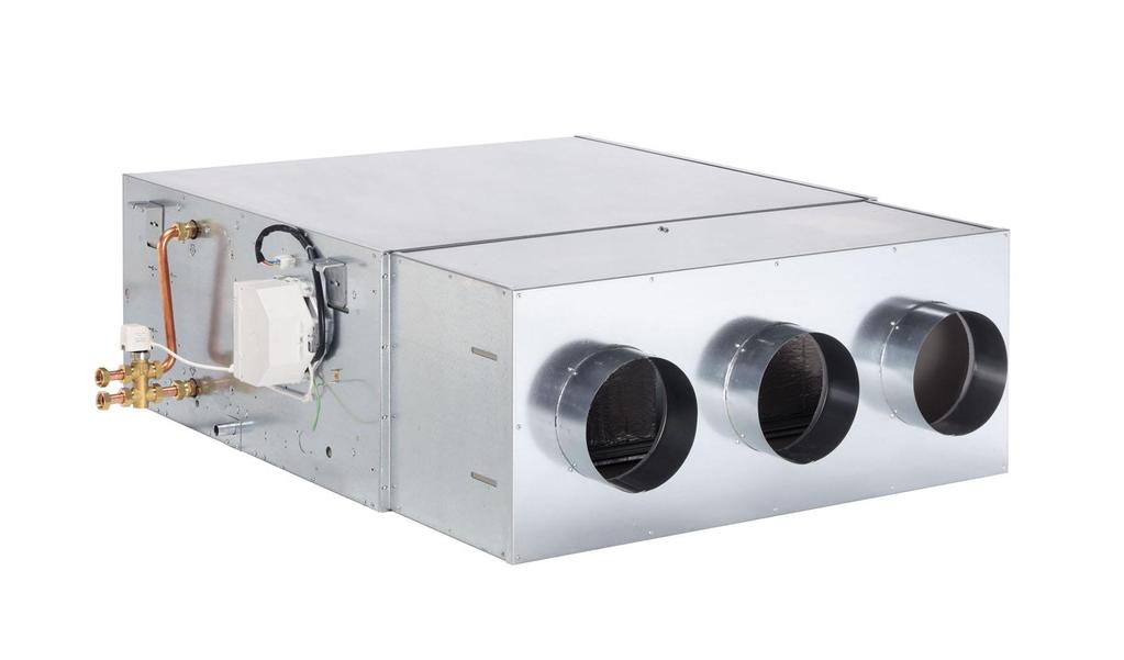
5 3. COMPONENTS 3.1 Structure The structure is made of galvanized steel. A particular manufacturing process gives stiffness to the structure: in this way all risks of vibration (which causes unpleasant noise) are strongly reduced. All the inner elements that could be cooled are completely lined with a polyurethane foam layer, which is not only a thermal insulation material but also a good sound attenuator. Self-extinguishing grade in accordance to norms: Class 1 UNI 8457 UNI In order to facilitate all maintenance operations, the structure is divided in 3 separate and independent sections: Condensate tray Fan deck Air filter. The air intake and outlet are provided with a 21 mm flange for an easy connection to the air duct. The YEFB fan coils can be installed on the ceiling by using the four fixing brackets always supplied with every unit. Legenda 1 Structure 2 Fixing support 3 Filter 4 Fan deck 5 Standard coil 6 Additional coil (2 or 3 rows) 7 Condensate tray 8 Access panel to fan deck 9 Access panel to condensate tray 10 Access panel to filter 11 Water discharge fixing supports 12 Electric box 4
.")
6 3.2 Coils For each unit size there are 2, 3 and 4 row coils available; for 4 pipe systems it is possible to install a 2 or 3 row coil. It is therefore possible to have a combination of imum 7 rows (4 row cooling + 3 row heating). For models 060 and 070 are also 5 row coils available which can be combined with additional 2 or 3 row coils. All coils consist of 3/8" external diameter copper pipes mechanically expanded to the aluum fin packs, provided with copper headers and brass soldering connections. Max. operating pressure 1,6 MPa, testing pressure 2,8 MPa. For the sizes 020, 030, 040 e 050 each header is provided with a very handy air valve, to allow air venting or water drainage from the coil. The air valve can be easily reached from the outside of the unit. For the sizes 060 and 070 the air vent valve are not present, therefore it is necessary to provide in the pipe connection a system for the water discharge and air venting of the coil. YEFB units can be ordered with right (standard) or left water connections, so defined when facing the air outlet. If necessary, however the coils can be easily removed and reversed on site. Water connections are 1/2" F (female threaded) for sizes 020, 030, 040, 050 1" M (male threaded) for size 060 and Fan deck The fan deck is composed by a 3 speed motor and 2 centrifugal galvanized steel scrolls. The motor and the scrolls are fixed on a rigid galvanized steel 1,5 mm thick basement. All motors are provided with permanently connected capacitor and thermal protection of the windings with automatic recharge; single phase 50/60 Hz for size 020 and single phase 50 Hz for sizes 030, 040, 050, 060 and 070. For all sizes the power supply is 230V± 10%. Each fan assembly is dynamically balanced, to reduce noise and wear of the components to imum levels; it can easily be removed for maintenance operation. 5
7 3.4 Condensate tray The condensate tray is made of galvanized steel and it is completely insulated by a 12 mm thick closed cell polyurethane foam layer. The condensed water is discharged from both sides (left or right) through a 20 mm diameter header. 3.5 Air filter The air filter consists of a washable polyester acrylic fiber, filtration class G3. A filter with higher filtering grade (G4 or F5) is also available upon request for each model. The particular pleated shape of the filter, protected by a metal frame, allows to have a big filtering surface with only 45 mm thickness. The filter section can be easily removed for cleaning and maintenance operation. 3.6 Standard electrical panel IP30 All models are provided with a teral board with screw terals contained in a self extinguishing ABS plastic box (IP30). For sizes a supporting relay is installed as standard on the electrical panel, where the power supply must be connected. The electric box must be fixed on the pre-arranged position on the side of the YEFB unit and connected with a «plug and play» system to the plug already present on the side itself. Every YEFB model is supplied with an electric wiring diagram showing all the electrical components, accessories factory fitted and/or remote controllers ordered together with the unit. Everything must be correctly wired in accordance to the diagram, to obtain the requested working conditions of the unit Electrical panel IP55 (optional) Electrical panel composed by a teral board with screw terals contained in a high protection box (IP55). Available on request. 3.7 Packing Every unit is packed in a carton box and lays on a wooden pallet. Legend 1 Label on packing 2 Label on internal structure 3 Box with fixing brackets and accessories 6
8 4. ELECTRICAL ACCESSORIES 4.1 Electric box CBL10 Self-extinguishing plastic box (class V0), which contains a 12 pole teral board and a double insulated transformer (230/24 V~10 VA), for the electrical connection of the modulating valves. It is supplied as standard for sizes 020 and 030 when the regulators CER10/B and CER30/B are requested. 4.2 Electric box CBL20 Self-extinguishing plastic box (class V0), which contains a 12 pole teral board and a power relay card (230 V~): this card is requested either when an electric heater is mounted on the fancoil unit or to control the fan speeds in Master/Slave configuration. It can be combined with the following regulators: CMR00, CMR10, CER00 and CER20. It is always supplied as standard for units size Electric box CBL30 Self-extinguishing plastic box (class V0), which contains a 12 pole teral board, a double insulated transformer (230/24 V~10 VA) for the electrical connection of the modulating valves and/or 24 V~ controls, a power relay card (24 V~), which is requested to control the fan speeds in Master/Slave configuration. It can be combined with the following regulators: CER11, CER31, CER00 (with power supply 24 V~) and CER20 (with power supply 24 V~). It is always supplied as standard for units size 040 and 070 when ordering the CER11 or CER 31 controls. JOHNSON CONTROLS recommend using also on sizes 020 e 030 the CBL30 electric box every time that modulating valves are installed. 4.4 Electrical heater KREL Additional module for Electrical heater supplied with 2 safety thermostats, one with automatic resetting and the other one with manual resetting, a power relay card and a teral board for the electrical connection. The table A shows the power of the electric heater for each unit size. EBH Power [kw] Power supply [V-ph-Hz] , , ,


9 4.5 Regulating systems A complete range of controllers is available for the YEFB ducted units: speed selectors, electronic controls, microprocessor controls and digital regulators with Supervision system via Bus connection. For more information please refer to the technical manual or visit Johnson Controls web site. 4.6 PC Condensate pump The condensate pump is necessary when the traditional water discharge is not allowed. It is always supplied separately. The power of the pump is different for the different models where it has to be installed. Functions: forced evacuation of the condensed water. PC Technical features for sizes 020 and 030: Max flow rate 10 l/h Max suction head 2 m Max discharge head 6 m Electric power 18 W Electric voltage 230 V~ 50/60 Hz Alarm contact NC 8 A 250 V Detection levels in mm ON: 16, OFF: 11, Alarm: 19 Sound level at 3.3 ft 25,1 dba Protection IP 20 Detection remote Thermal protection (overheating) 90 C Safety standards CE RhOS and WEEE directives complies 8

10 PC Technical features for sizes : Max flow rate 20 l/h Max suction head 3 m Max discharge head 10 m (flow=4 l/h) Electric power 14 W Electric voltage 230 V~ 50/60 Hz Alarm contact NC 8 A resistive 250 V Detection levels in mm ON: 16, OFF: 11, Alarm: 19 Sound level at 3.3 ft < 20 dba Protection IP 20 Detection remote Thermal protection (overheating) 90 C (automatic reset) Safety standards CE RhOS and WEEE directives complies 9
11 5. HYDRAULIC ACCESSORIES 5.1 J3B2 J3B2 ON/OFF 3-way valves with 4 water connections, 3/4", 230 V~, for 2 or 4 pipe systems The ON/OFF 3-way regulating valves with bypass are provided with thermoelectric actuator and connection tubes. The direct water flow is closed by not supplying power to the actuator. They are suitable for fan coils size and available also with 24 V~. They are always supplied loose together with their proper insulating shell. 5.2 J3C2 ON/OFF 3-way valves with 4 water connections, 1", 230 V~, for 2 or 4 pipe systems The ON/OFF 3-way regulating valves with bypass are provided with thermoelectric actuator and connection tubes. The direct water flow is closed by not supplying power to the actuator. They are suitable for fan coils size and available also with 24 V~. They are always supplied loose together with their proper insulating shell. 5.3 J3BM Modulating 3-way valves with 4 water connections, 3/4", 24 V~, for 2 or 4 pipe systems The modulating 3-way regulating valves with bypass are provided with modulating actuator and connection tubes. The direct water flow is closed by not supplying power to the actuator. They are suitable for fan coils size They are always supplied loose together with their proper insulating shell. 5.4 J3CM Modulating 3-way valves with 4 water connections, 1", 24 V~, for 2 or 4 pipe systems The modulating 3-way regulating valves with bypass are provided with modulating actuator and connection tubes. The direct water flow is closed by not supplying power to the actuator. They are suitable for fan coils size They are always supplied loose together with their proper insulating shell. BODY VALVE'S TECHNICAL FEAURES J3B2 - J3BM J3C2 - J3CM Noal pressure PN16 PN16 Water connection ¾ Gf 1 Gf Kv: water flow rate 2,5 4,5 Max. press. Drop 150 kpa 70 kpa Fluid temperature C in compliance to PED (Pressure Equipment Directive) 23/97/CE par. 3 point 3. ACTUATOR TECHNICAL FEATURES Power supply V- PH-HZ Running time s Control signal Vcc Protection grade Controllers compatibility J3B2-J3C (60) IP44 TAD10-CMR00- CMR10-CER00- CER20-OMNIBUS J3BM-J3CM (60) 0 10 IP40 CER10/B-CER11- CER30/B-CER31- OMNIBUS 10
12 Kvs 4.5 DN25 Water flow [l/h] Kvs 2.5 DN20 Pressure drop [kpa] Graphic pressure drop valves kv = 2,5 kv=4,5 The consultant has the responsibility of the correct choice of the valve. In order to choose the correct type of valve it is necessary to know the system s technical specifications; for this reason the consultant should take full responsibility for this choice. 11
13 6. OTHER ACCESSORIES 6.1 PM Air delivery plenum The air delivery plenum is made of galvanized steel sheet, insulated inside with polyurethane foam, 12 mm thick, provided with spigots for the connection to the air ducts and with fixing supports. It must be installed on the air outlet of the unit. 6.2 PA Air intake plenum The air intake plenum is made of galvanized steel sheet, insulated inside with polyurethane foam, 12 mm thick, provided with spigots for the connection to the air ducts and with fixing supports. It must be installed on the air inlet of the unit. Mod N. Collari A 403,6 513,6 B 961,6 1211,6 1607,6 C 306, G4 Air filter High filtering grade air filter consisting of a polyester acrylic fiber foam, filtration class G F5 Air filter High filtering grade air filter consisting of a polyester acrylic fiber foam, filtration class F RAL Painting The complete structure of the unit can be painted with oven dried epoxy powders. The standard colour is white (RAL 9001) but the full range of RAL colours is available upon request, with possible delays in the delivery time. 12
14 7. TECHNICAL DATA 7.1 Air volumes MOD SPEED
15 7.2 Capacities for YEFB 020 at different external static pressures [Pa] Cooling and heating capacities with the same water flow Cooling: Room temperature 27 C D.B. - 48% R.H. - Water temperature: 7/12 C Heating: Room temperature: 20 C - 50% R.H. - Water temperature: 50 C MOD SPEED Total cooling capacity [kw] 4,25 4,05 3,71 3,28 2,54 1,86 Sensible cooling capacity [kw] 3,66 3,49 3,20 2,84 2,22 1,66 Water flow [l/h] Water press. drop (cool.) [kpa] 12,7 11,6 9,9 7,9 5,0 2,8 Heating capacity [kw] 6,09 5,75 5,29 4,64 3,59 2,63 Water press. drop (heat.) [kpa] 12,4 11,3 9,6 7,7 4,8 2,7 Total cooling capacity [kw] 3,39 3,17 2,88 2,45 1,83 Sensible cooling capacity [kw] 2,90 2,73 2,48 2,15 1,64 Water flow [l/h] Water press. drop (cool.) [kpa] 8,0 7,1 5,9 4,4 2,6 Heating capacity [kw] 5,01 4,66 4,22 3,61 2,70 Water press. drop (heat.) [kpa] 7,5 6,7 5,6 4,1 2,4 Total cooling capacity [kw] 2,83 2,44 2,09 1,62 Sensible cooling capacity [kw] 2,22 1,94 1,66 1,33 Water flow [l/h] Water press. drop (cool.) [kpa] 5,7 4,4 3,3 2,1 Heating capacity [kw] 4,16 3,6 3,07 2,44 Water press. drop (heat.) [kpa] 4,9 3,7 2,8 1,8 Total cooling capacity [kw] 5,97 5,62 5,18 4,52 3,46 2,49 Sensible cooling capacity [kw] 5,03 4,73 4,36 3,80 2,92 2,1 Water flow [l/h] Water press. drop (cool.) [kpa] 33,6 30,1 25,9 20,2 12,4 6,8 Heating capacity [kw] 8,03 7,55 6,89 5,96 4,5 3,2 Water press. drop (heat.) [kpa] 32,5 29,2 25,1 19,5 11,9 6,5 Total cooling capacity [kw] 4,69 4,34 3,90 3,30 2,43 Sensible cooling capacity [kw] 3,89 3,61 3,25 2,78 2 Water flow [l/h] Water press. drop (cool.) [kpa] 20,5 17,8 14,6 10,8 6,2 Heating capacity [kw] 6,44 5,95 5,33 4,48 3,27 Water press. drop (heat.) [kpa] 19,3 16,7 13,7 10,1 5,8 Total cooling capacity [kw] 3,82 3,30 2,78 2,17 Sensible cooling capacity [kw] 2,91 2,51 2,14 1,68 Water flow [l/h] Water press. drop (cool.) [kpa] 14,1 10,8 7,9 5,1 Heating capacity [kw] 5,21 4,46 3,74 2,91 Water press. drop (heat.) [kpa] 12,0 9,1 6,7 4,2 Total cooling capacity [kw] 8,27 7,79 7,14 6,25 4,90 3,07 Sensible cooling capacity [kw] 6,76 6,39 5,90 5,09 3,87 2,32 Water flow [l/h] Water press. drop (cool.) [kpa] 36,5 32,8 27,9 21,8 14,0 6,0 Heating capacity [kw] 10,23 9,61 8,79 7,66 5,96 3,73 Water press. drop (heat.) [kpa] 33,0 29,6 25,2 19,7 12,6 527 Total cooling capacity [kw] 6,59 6,06 5,40 4,59 3,45 5,3 Sensible cooling capacity [kw] 5,26 4,79 4,23 3,52 2,58 Water flow [l/h] Water press. drop (cool.) [kpa] 25,4 21,8 17,7 13,2 7,9 Heating capacity [kw] 8,46 7,78 6,95 5,87 4,41 Water press. drop (heat.) [kpa] 22,3 19,1 15,5 11,5 6,8 Total cooling capacity [kw] 4,95 4,08 3,33 2,59 Sensible cooling capacity [kw] 3,70 3,01 2,42 1,84 Water flow [l/h] Water press. drop (cool.) [kpa] 16,5 11,7 8,1 5,2 Heating capacity [kw] 6,27 5,18 4,23 3,22 Water press. drop (heat.) [kpa] 14,4 10,1 7,0 4,4 14
16 7.2.2 Heating capacities Room temperature: 20 C - 50% R.H. - Water temperature: 70/60 C MOD SPEED Heating capacity [kw] 10,80 10,18 9,43 8,40 6,80 4,25 Water flow [l/h] Water press. drop (heat.) [kpa] 19,5 17,5 15,2 12,2 8,2 3,9 Heating capacity [kw] 9,29 8,65 7,84 6,78 5,31 Water flow [l/h] Water press. drop (heat.) [kpa] 13,6 11,9 9,9 7,6 4,8 Heating capacity [kw] 7,30 6,19 5,22 4,11 Water flow [l/h] Water press. drop (heat.) [kpa] 7,9 5,8 4,2 2,7 Heating capacity [kw] 14,00 13,21 12,13 10,66 8,42 5,4 Water flow [l/h] Water press. drop (heat.) [kpa] 44,1 39,6 33,8 26,6 17,2 7,6 Heating capacity [kw] 11,79 10,88 9,77 8,33 6,37 Water flow [l/h] Water press. drop (heat.) [kpa] 29,7 25,5 21,0 15,6 9,5 Heating capacity [kw] 8,98 7,50 6,18 4,77 Water flow [l/h] Water press. drop (heat.) [kpa] 16,2 11,6 8,2 5,1 Heating capacity [kw] 17,26 16,21 14,82 12,89 10,05 6,27 Water flow [l/h] Water press. drop (heat.) [kpa] 36,1 32,1 27,2 21,0 13,3 5,6 Heating capacity [kw] 14,34 13,16 11,76 9,91 7,45 Water flow [l/h] Water press. drop (heat.) [kpa] 26,3 22,4 18,2 13,3 7,9 Heating capacity [kw] 10,59 8,73 7,12 5,41 Water flow [l/h] Water press. drop (heat.) [kpa] 16,4 11,5 7,9 4,8 15
17 7.3 Capacities for YEFB 030 at different external static pressures [Pa] Cooling and heating capacities with the same water flow Cooling: Room temperature 27 C D.B. - 48% R.H. - Water temperature: 7/12 C Heating: Room temperature: 20 C - 50% R.H. - Water temperature: 50 C MOD SPEED Total cooling capacity [kw] 6,43 6,25 6,04 5,81 5,51 5,08 4,27 2,96 Sensible cooling capacity [kw] 5,68 5,44 5,22 4,89 4,59 4,14 3,39 2,36 Water flow [l/h] Water press. drop (cool.) [kpa] 25,1 23,8 22,3 20,8 18,9 16,2 11,7 5,9 Heating capacity [kw] 9,94 9,56 9,09 8,56 7,92 7,04 5,70 3,80 Water press. drop (heat.) [kpa] 22,4 21,3 20,0 18,6 16,9 14,5 10,5 5,2 Total cooling capacity [kw] 5,44 5,30 5,15 4,91 4,57 4,06 3,44 2,37 Sensible cooling capacity [kw] 4,59 4,42 4,26 4,01 3,60 3,15 2,65 1,77 Water flow [l/h] Water press. drop (cool.) [kpa] 18,3 17,5 16,5 15,1 13,2 10,5 7,8 4,0 Heating capacity [kw] 8,01 7,75 7,39 6,90 6,19 5,36 4,42 3,01 Water press. drop (heat.) [kpa] 16,4 15,7 14,9 13,6 11,8 9,4 6,9 3,4 Total cooling capacity [kw] 4,71 4,61 4,44 4,20 3,82 3,21 2,55 1,47 Sensible cooling capacity [kw] 3,87 3,75 3,61 3,41 3,02 2,53 1,89 1,03 Water flow [l/h] Water press. drop (cool.) [kpa] 14,0 13,5 12,6 11,3 9,4 6,8 4,5 1,7 Heating capacity[kw] 6,76 6,57 6,27 5,83 5,04 4,11 3,19 1,89 Water press. drop (heat.) [kpa] 12,5 12,0 11,2 10,1 8,4 6,1 3,9 1,4 Total cooling capacity [kw] 9,24 8,92 8,60 8,19 7,73 7,03 5,85 3,94 Sensible cooling capacity [kw] 7,85 7,55 7,20 6,80 6,28 5,60 4,54 2,78 Water flow [l/h] Water press. drop (cool.) [kpa] 69,0 64,6 60,5 55,3 49,8 41,7 29,6 14,1 Heating capacity [kw] 13,46 12,87 12,20 11,44 10,50 9,25 7,28 4,63 Water press. drop (heat.) [kpa] 61,4 57,6 53,8 49,2 44,3 37,2 26,3 12,5 Total cooling capacity [kw] 7,62 7,42 7,17 6,80 6,24 5,52 4,62 3,17 Sensible cooling capacity [kw] 6,29 6,07 5,77 5,36 4,82 4,10 3,27 2,10 Water flow [l/h] Water press. drop (cool.) [kpa] 48,2 45,9 43,0 38,9 33,1 26,3 19,0 9,6 Heating capacity [kw] 10,61 10,21 9,71 8,97 7,97 6,80 5,49 3,59 Water press. drop (heat.) [kpa] 43,0 41,0 38,5 34,8 29,6 23,4 16,7 8,3 Total cooling capacity [kw] 6,51 6,39 6,16 5,82 5,15 4,33 3,41 2,01 Sensible cooling capacity [kw] 5,15 5,00 4,84 4,51 3,81 3,00 2,24 1,27 Water flow [l/h] Water press. drop (cool.) [kpa] 36,0 34,8 32,5 29,3 23,2 16,7 10,6 4,1 Heating capacity [kw] 8,81 8,49 8,10 7,44 6,34 5,06 3,82 2,17 Water press. drop (heat.) [kpa] 31,9 30,7 28,7 25,8 20,5 14,8 9,4 3,6 Total cooling capacity [kw] 10,93 10,51 10,12 9,64 9,03 8,12 6,61 4,22 Sensible cooling capacity [kw] 9,39 9,10 8,62 8,12 7,46 6,46 4,88 2,89 Water flow [l/h] Water press. drop (cool.) [kpa] 40,3 37,5 35,0 32,0 28,4 23,3 15,9 6,9 Heating capacity [kw] 15,79 15,06 14,24 13,30 12,15 10,59 8,19 5,03 Water press. drop (heat.) [kpa] 35,8 33,3 31,1 28,4 25,2 20,7 14,1 6,1 Total cooling capacity [kw] 8,90 8,62 8,29 7,81 7,08 6,16 5,03 3,39 Sensible cooling capacity [kw] 7,27 6,95 6,53 5,96 5,20 4,36 3,44 2,21 Water flow [l/h] Water press. drop (cool.) [kpa] 27,5 25,9 24,0 21,5 17,9 13,8 9,5 4,7 Heating capacity [kw] 12,23 11,74 11,11 10,20 8,97 7,56 6,01 3,83 Water press. drop (heat.) [kpa] 24,5 23,1 21,5 19,2 16,0 12,3 8,4 4,0 Total cooling capacity [kw] 7,46 7,29 7,00 6,54 5,72 4,66 3,63 2,19 Sensible cooling capacity [kw] 5,78 5,55 5,27 4,80 4,03 3,14 2,35 1,36 Water flow [l/h] Water press. drop (cool.) [kpa] 19,8 19,0 17,6 15,5 12,0 8,2 5,2 2,1 Heating capacity [kw] 9,99 9,64 9,13 8,36 7,03 5,51 4,09 2,26 Water press. drop (heat.) [kpa] 17,5 16,8 15,6 13,7 10,7 7,3 4,6 1,8 16
18 7.3.2 Heating capacities Room temperature: 20 C - 50% R.H. - Water temperature: 70/60 C MOD SPEED Heating capacity [kw] 17,44 16,76 15,91 15,03 13,81 12,20 9,77 6,47 Water flow [l/h] Water press. drop (heat.) [kpa] 39,9 37,1 33,7 30,3 25,9 20,6 13,5 6,2 Heating capacity [kw] 14,01 13,49 12,91 11,98 10,69 9,23 7,56 5,13 Water flow [l/h] Water press. drop (heat.) [kpa] 26,6 24,8 22,8 19,8 16,0 12,1 8,2 4,0 Heating capacity [kw] 11,78 11,39 10,87 10,06 8,68 7,02 5,42 3,24 Water flow [l/h] Water press. drop (heat.) [kpa] 19,1 17,9 16,4 14,1 10,7 7,2 4,4 1,7 Heating capacity [kw] 23,15 22,19 20,96 19,64 17,95 15,74 12,31 7,78 Water flow [l/h] Water press. drop (heat.) [kpa] 94,3 87,2 78,4 69,5 58,9 46,1 29,1 12,3 Heating capacity [kw] 18,12 17,49 16,53 15,26 13,51 11,45 9,22 6,00 Water flow [l/h] Water press. drop (heat.) [kpa] 59,9 56,1 50,5 43,4 34,5 25,2 16,7 7,5 Heating capacity [kw] 14,98 14,48 13,72 12,61 10,71 8,48 6,38 3,62 Water flow [l/h] Water press. drop (heat.) [kpa] 41,7 39,1 35,3 30,2 22,2 14,3 8,4 2,9 Heating capacity [kw] 27,20 25,84 24,42 22,76 20,72 17,97 13,81 8,45 Water flow [l/h] Water press. drop (heat.) [kpa] 54,2 49,3 44,4 39,0 32,8 25,2 15,4 6,1 Heating capacity [kw] 20,85 20,02 18,93 17,31 15,18 12,74 10,09 6,40 Water flow [l/h] Water press. drop (heat.) [kpa] 33,1 30,7 27,7 23,4 18,3 13,1 8,5 3,6 Heating capacity [kw] 16,98 16,35 15,47 14,14 11,83 9,24 6,83 3,76 Water flow [l/h] Water press. drop (heat.) [kpa] 22,5 20,9 18,8 15,9 11,4 7,2 4,1 1,4 17
19 7.4 Capacities for YEFB 040 at different external static pressures [Pa] Cooling and heating capacities with the same water flow Cooling: Room temperature 27 C D.B. - 48% R.H. - Water temperature: 7/12 C Heating: Room temperature: 20 C - 50% R.H. - Water temperature: 50 C MOD SPEED Total cooling capacity [kw] 8,16 7,95 7,67 7,46 7,15 6,86 6,35 5,79 4,99 2,94 Sensible cooling capacity [kw] 7,40 7,16 6,85 6,59 6,29 5,93 5,50 4,82 4,10 2,36 Water flow [l/h] Water press. drop (cool.) [kpa] 27,3 26,1 24,4 23,2 21,4 19,7 16,9 14,0 10,4 3,6 Heating capacity [kw] 12,37 11,95 11,52 10,98 10,36 9,63 8,70 7,50 5,98 2,82 Water press. drop (heat.) [kpa] 24,9 23,7 22,2 21,1 19,4 17,9 15,4 12,8 9,5 3,3 Total cooling capacity [kw] 6,93 6,86 6,70 6,50 6,25 5,93 5,44 4,77 3,97 2,17 Sensible cooling capacity [kw] 6,10 5,91 5,75 5,57 5,29 4,98 4,47 3,90 3,22 1,74 Water flow [l/h] Water press. drop (cool.) [kpa] 20,2 19,8 19,0 17,9 16,6 14,9 12,6 9,7 6,7 2,0 Heating capacity [kw] 10,40 10,26 10,01 9,66 9,18 8,45 7,48 6,18 4,66 1,84 Water press. drop (heat.) [kpa] 18,4 18,0 17,2 16,3 15,1 13,6 11,5 8,9 6,2 1,9 Total cooling capacity [kw] 6,15 5,93 5,75 5,51 5,21 4,83 4,34 3,77 3,01 1,06 Sensible cooling capacity [kw] 5,96 5,64 5,20 4,80 4,40 3,98 3,50 2,98 2,38 0,88 Water flow [l/h] Water press. drop (cool.) [kpa] 16,3 15,1 14,1 13,0 11,6 10,1 8,3 6,4 4,3 0,7 Heating capacity [kw] 8,79 8,42 8,02 7,57 7,07 6,49 5,81 4,99 3,98 1,56 Water press. drop (heat.) [kpa] 14,9 13,9 13,0 12,0 10,7 9,2 7,5 5,7 3,6 0,5 Total cooling capacity [kw] 11,43 11,13 10,82 10,41 9,99 9,49 8,81 7,90 6,72 3,81 Sensible cooling capacity [kw] 10,13 9,85 9,40 9,14 8,58 8,05 7,40 6,54 5,46 2,96 Water flow [l/h] Water press. drop (cool.) [kpa] 72,1 68,7 65,2 60,7 56,1 50,8 43,8 35,3 25,5 8,2 Heating capacity [kw] 16,56 15,97 15,32 14,60 13,74 12,68 11,39 9,73 7,63 3,39 Water press. drop (heat.) [kpa] 65,5 62,3 59,1 54,9 50,8 46,0 39,6 32,0 23,1 7,5 Total cooling capacity [kw] 9,62 9,47 9,27 8,96 8,56 8,07 7,35 6,41 5,26 2,75 Sensible cooling capacity [kw] 8,29 8,12 7,85 7,53 7,20 6,65 5,97 5,15 4,15 2,10 Water flow [l/h] Water press. drop (cool.) [kpa] 52,3 50,9 49,0 45,9 42,0 37,4 31,1 23,8 16,0 4,4 Heating capacity [kw] 13,69 13,45 13,10 12,60 11,90 10,91 9,56 7,81 5,77 2,15 Water press. drop (heat.) [kpa] 47,4 46,1 44,3 41,5 38,0 33,9 28,2 21,6 14,6 4,1 Total cooling capacity [kw] 8,38 8,09 7,81 7,44 6,98 6,46 5,76 4,92 3,86 1,44 Sensible cooling capacity [kw] 7,34 6,97 6,58 6,14 5,66 5,13 4,50 3,77 2,90 1,03 Water flow [l/h] Water press. drop (cool.) [kpa] 40,8 37,9 35,2 32,0 28,4 24,5 19,9 14,9 9,6 1,7 Heating capacity [kw] 11,42 10,87 10,29 9,67 8,96 8,17 7,22 6,12 4,76 1,74 Water press. drop (heat.) [kpa] 37,1 34,7 32,3 29,4 26,0 22,3 17,8 13,1 8,2 1,2 Total cooling capacity [kw] 13,59 13,20 12,84 12,34 11,79 11,14 10,28 9,18 7,71 4,17 Sensible cooling capacity [kw] 12,23 11,77 11,31 10,81 10,23 9,52 8,68 7,58 6,18 3,09 Water flow [l/h] Water press. drop (cool.) [kpa] 42,5 40,3 38,3 35,6 32,6 29,2 25,0 19,9 14,1 4,2 Heating capacity [kw] 19,41 18,68 17,90 17,00 15,94 14,69 13,11 11,10 8,60 3,67 Water press. drop (heat.) [kpa] 38,5 36,5 34,7 32,2 29,5 26,4 22,6 18,0 12,7 3,8 Total cooling capacity [kw] 11,34 11,09 10,82 10,44 9,92 9,30 8,44 7,28 5,86 2,96 Sensible cooling capacity [kw] 9,62 9,31 8,94 8,52 8,02 7,36 6,56 5,57 4,42 2,18 Water flow [l/h] Water press. drop (cool.) [kpa] 30,4 29,2 27,9 26,1 23,6 20,9 17,2 12,9 8,4 2,2 Heating capacity [kw] 15,84 15,51 15,10 14,47 13,61 12,43 10,80 8,73 6,37 2,29 Water press. drop (heat.) [kpa] 27,5 26,4 25,2 23,5 21,4 18,9 15,6 11,7 7,7 2,0 Total cooling capacity [kw] 9,71 9,39 8,98 8,52 7,97 7,31 6,49 5,45 4,19 1,51 Sensible cooling capacity [kw] 7,85 7,45 7,03 6,56 6,05 5,46 4,78 3,98 3,02 1,06 Water flow [l/h] Water press. drop (cool.) [kpa] 23,0 21,4 19,6 17,7 15,5 13,2 10,6 7,7 4,8 0,8 Heating capacity [kw] 13,04 12,37 11,68 10,92 10,07 9,13 8,01 6,70 5,14 1,79 Water press. drop (heat.) [kpa] 20,9 19,5 17,9 16,2 14,2 12,0 9,5 6,8 4,1 0,6 18
20 7.4.2 Heating capacities Room temperature: 20 C - 50% R.H. - Water temperature: 70/60 C MOD SPEED Heating capacity [kw] 21,57 20,82 20,06 19,11 20,99 16,59 14,97 12,78 10,07 4,59 Water flow [l/h] Water press. drop (heat.) [kpa] 42,0 39,4 36,7 33,5 40,9 25,6 21,0 15,4 9,7 2,1 Heating capacity [kw] 18,05 17,80 17,36 16,80 18,15 14,61 12,86 10,54 7,84 2,94 Water flow [l/h] Water press. drop (heat.) [kpa] 30,1 29,3 28,0 26,3 30,9 20,1 15,7 10,7 6,1 0,9 Heating capacity [kw] 15,22 14,50 13,76 13,01 15,96 11,10 9,94 8,52 6,77 2,68 Water flow [l/h] Water press. drop (heat.) [kpa] 22,1 20,2 18,2 16,3 24,6 12,0 9,6 7,1 4,5 0,8 Heating capacity [kw] 28,41 27,43 26,23 24,97 27,65 21,61 19,28 16,36 12,72 5,53 Water flow [l/h] Water press. drop (heat.) [kpa] 98,2 92,1 84,7 77,2 95,6 58,6 47,1 34,2 21,0 4,2 Heating capacity [kw] 23,40 22,98 22,41 21,51 23,53 18,56 16,20 13,11 9,60 3,48 Water flow [l/h] Water press. drop (heat.) [kpa] 68,3 66,1 63,1 58,4 70,2 44,0 33,9 22,6 12,5 1,8 Heating capacity [kw] 19,43 18,44 17,47 16,38 20,57 13,77 12,19 10,28 8,00 2,91 Water flow [l/h] Water press. drop (heat.) [kpa] 49,0 44,3 39,9 35,2 55,3 25,1 19,8 14,3 8,8 1,3 Heating capacity [kw] 33,26 31,95 30,60 28,98 32,43 24,89 22,13 18,67 14,34 6,01 Water flow [l/h] Water press. drop (heat.) [kpa] 56,2 52,2 48,1 43,5 54,9 32,5 26,0 18,7 11,2 2,1 Heating capacity [kw] 27,01 26,49 25,70 24,63 27,22 21,05 18,25 14,66 10,60 3,72 Water flow [l/h] Water press. drop (heat.) [kpa] 38,1 36,8 34,7 32,0 39,3 23,8 18,1 11,9 6,4 0,9 Heating capacity [kw] 22,12 20,96 19,74 18,42 23,58 15,35 13,46 11,25 8,62 2,99 Water flow [l/h] Water press. drop (heat.) [kpa] 26,6 24,0 21,4 18,7 30,5 13,2 10,2 7,2 4,3 0,6 19
21 7.5 Capacities for YEFB 050 at different external static pressures [Pa] Cooling and heating capacities with the same water flow Cooling: Room temperature 27 C D.B. - 48% R.H. - Water temperature: 7/12 C Heating: Room temperature: 20 C - 50% R.H. - Water temperature: 50 C MOD SPEED Total cooling capacity [kw] 9,30 9,14 8,82 8,59 8,26 7,81 7,27 6,55 5,70 3,92 Sensible cooling capacity [kw] 8,42 8,32 7,98 7,79 7,38 6,91 6,39 5,65 4,86 3,20 Water flow [l/h] Water press. drop (cool.) [kpa] 35,6 34,6 32,4 30,8 28,7 25,7 22,3 18,0 13,5 6,3 Heating capacity [kw] 13,79 13,48 13,04 12,62 12,03 11,38 10,51 9,40 8,06 5,37 Water press. drop (heat.) [kpa] 32,6 31,6 29,6 28,1 26,1 23,4 20,3 16,5 12,5 5,9 Total cooling capacity [kw] 8,22 8,04 7,91 7,60 7,32 6,92 6,41 5,82 5,06 3,43 Sensible cooling capacity [kw] 7,30 7,19 6,88 6,73 6,33 5,90 5,45 4,90 4,26 2,83 Water flow [l/h] Water press. drop (cool.) [kpa] 28,1 27,0 26,2 24,2 22,5 20,2 17,5 14,5 11,1 5,2 Heating capacity [kw] 12,30 11,95 11,53 11,05 10,44 9,81 9,01 8,12 7,09 4,80 Water press. drop (heat.) [kpa] 25,8 24,7 24,0 22,2 20,6 18,5 15,9 13,2 10,0 4,7 Total cooling capacity [kw] 7,38 7,30 7,10 6,89 6,57 6,20 5,70 5,17 4,60 3,34 Sensible cooling capacity [kw] 4,59 4,72 4,90 4,94 5,06 4,95 4,76 4,42 3,98 2,84 Water flow [l/h] Water press. drop (cool.) [kpa] 22,9 22,4 21,2 20,0 18,3 16,4 14,0 11,7 9,4 5,2 Heating capacity [kw] 11,03 10,72 10,31 9,84 9,28 8,60 7,83 7,06 6,26 4,55 Water press. drop (heat.) [kpa] 20,9 20,6 19,7 18,7 17,1 15,2 12,8 10,4 8,1 4,1 Total cooling capacity [kw] 13,29 12,90 12,56 12,14 11,59 10,93 10,10 9,07 7,81 5,19 Sensible cooling capacity [kw] 11,90 11,50 11,18 10,68 10,21 9,51 8,69 7,72 6,51 4,19 Water flow [l/h] Water press. drop (cool.) [kpa] 97,4 92,4 88,1 82,7 75,7 67,5 57,7 46,4 34,2 15,0 Heating capacity [kw] 18,67 18,24 17,64 16,96 16,19 15,18 13,91 12,31 10,44 6,66 Water press. drop (heat.) [kpa] 88,7 84,0 80,0 75,0 68,7 61,3 52,5 42,5 31,5 14,1 Total cooling capacity [kw] 11,51 11,29 10,99 10,63 10,14 9,57 8,81 7,91 6,90 4,51 Sensible cooling capacity [kw] 10,10 9,90 9,51 9,14 8,63 8,07 7,35 6,53 5,61 3,54 Water flow [l/h] Water press. drop (cool.) [kpa] 74,0 71,4 67,9 63,8 58,3 52,2 44,5 36,2 27,8 12,3 Heating capacity [kw] 16,48 15,99 15,37 14,66 13,81 12,85 11,74 10,48 9,03 5,87 Water press. drop (heat.) [kpa] 67,5 65,1 61,9 58,1 53,1 47,5 40,4 32,8 25,1 11,0 Total cooling capacity [kw] 10,34 10,14 9,85 9,50 9,07 8,47 7,75 6,96 6,14 4,31 Sensible cooling capacity [kw] 6,25 6,45 6,64 6,84 6,84 6,72 6,39 5,68 4,87 3,23 Water flow [l/h] Water press. drop (cool.) [kpa] 60,4 58,1 55,0 51,3 47,0 41,3 35,0 28,7 22,8 11,9 Heating capacity [kw] 14,63 14,16 13,60 12,91 12,12 11,12 10,06 8,97 7,86 5,50 Water press. drop (heat.) [kpa] 55,0 53,4 50,8 47,7 43,6 38,1 31,8 25,4 19,5 9,3 Total cooling capacity [kw] 15,86 15,52 15,02 14,42 13,85 12,99 11,92 10,60 9,02 5,81 Sensible cooling capacity [kw] 14,37 14,01 13,51 12,89 12,30 11,43 10,39 8,99 7,41 4,48 Water flow [l/h] Water press. drop (cool.) [kpa] 57,8 55,6 52,4 48,6 45,0 39,8 33,6 26,5 19,1 7,9 Heating capacity [kw] 22,15 21,56 20,84 19,98 19,01 17,74 16,18 14,20 11,88 7,38 Water press. drop (heat.) [kpa] 52,6 50,6 47,6 44,1 40,8 36,1 30,5 24,2 17,6 7,5 Total cooling capacity [kw] 13,70 13,43 13,04 12,56 11,96 11,20 10,25 9,13 7,86 4,97 Sensible cooling capacity [kw] 12,19 11,88 11,42 10,77 10,06 9,27 8,35 7,27 6,12 3,73 Water flow [l/h] Water press. drop (cool.) [kpa] 43,7 42,2 39,9 37,2 33,9 29,9 25,2 20,2 15,2 6,3 Heating capacity [kw] 19,33 18,75 17,97 17,06 16,02 14,85 13,47 11,89 10,17 6,42 Water press. drop (heat.) [kpa] 39,8 38,4 36,3 33,8 30,8 27,1 22,9 18,3 13,7 5,6 Total cooling capacity [kw] 12,22 11,94 11,66 11,13 10,60 9,84 8,93 7,96 6,94 4,72 Sensible cooling capacity [kw] 7,47 7,70 7,90 8,10 8,09 7,86 6,98 6,06 5,18 3,39 Water flow [l/h] Water press. drop (cool.) [kpa] 35,2 33,7 32,1 29,4 26,8 23,3 19,5 15,7 12,2 6,1 Heating capacity [kw] 17,05 16,45 15,76 14,93 13,92 12,71 11,41 10,07 8,75 5,97 Water press. drop (heat.) [kpa] 32,0 30,9 29,7 27,3 24,9 21,5 17,7 13,9 10,5 4,8 20
22 7.5.2 Heating capacities Room temperature: 20 C - 50% R.H. - Water temperature: 70/60 C MOD SPEED Heating capacity [kw] 23,91 23,47 22,80 21,93 20,99 19,74 18,20 16,25 13,90 9,18 Water flow [l/h] Water press. drop (heat.) [kpa] 52,3 50,6 47,9 44,5 40,9 36,3 31,0 24,7 18,1 8,0 Heating capacity [kw] 21,44 20,83 20,08 19,14 18,15 16,95 15,55 13,99 12,19 8,22 Water flow [l/h] Water press. drop (heat.) [kpa] 42,4 40,2 37,5 34,2 30,9 27,0 22,9 18,6 14,2 6,6 Heating capacity [kw] 19,18 18,64 17,90 17,01 15,96 14,76 13,44 12,09 10,75 7,78 Water flow [l/h] Water press. drop (heat.) [kpa] 34,2 32,6 30,4 27,8 24,6 21,1 17,4 13,9 10,9 5,5 Heating capacity [kw] 32,04 31,24 30,26 29,07 27,65 25,98 23,71 20,96 17,70 11,25 Water flow [l/h] Water press. drop (heat.) [kpa] 126,2 120,4 113,5 105,3 95,6 84,8 71,0 55,7 39,9 16,4 Heating capacity [kw] 28,27 27,42 26,26 24,99 23,53 21,88 19,97 17,76 15,29 9,92 Water flow [l/h] Water press. drop (heat.) [kpa] 99,2 93,8 86,4 78,7 70,2 61,0 51,1 40,7 30,4 13,1 Heating capacity [kw] 25,10 24,21 23,24 21,99 20,57 18,87 17,06 15,15 13,26 9,27 Water flow [l/h] Water press. drop (heat.) [kpa] 79,0 74,4 69,3 62,7 55,3 46,7 38,1 29,8 22,6 10,7 Heating capacity [kw] 37,84 36,88 35,58 34,16 32,43 30,25 27,53 24,15 20,13 12,42 Water flow [l/h] Water press. drop (heat.) [kpa] 73,3 70,0 65,5 60,6 54,9 48,0 40,0 30,9 21,7 8,4 Heating capacity [kw] 33,06 32,02 30,63 29,00 27,22 25,18 22,83 20,13 17,15 10,81 Water flow [l/h] Water press. drop (heat.) [kpa] 56,6 53,4 49,1 44,3 39,3 33,8 28,0 21,9 16,1 6,6 Heating capacity [kw] 29,09 28,03 26,81 25,35 23,58 21,49 19,27 16,98 14,74 10,04 Water flow [l/h] Water press. drop (heat.) [kpa] 44,4 41,7 38,6 34,9 30,5 25,4 20,4 15,8 11,8 5,3 21
23 7.6 Capacities for YEFB 060 at different external static pressures [Pa] Cooling and heating capacities with the same water flow Cooling: Room temperature 27 C D.B. - 48% R.H. - Water temperature: 7/12 C Heating: Room temperature: 20 C - 50% R.H. - Water temperature: 50 C MOD SPEED Total cooling capacity [kw] 12,85 12,69 12,60 12,45 12,24 12,06 11,82 11,27 10,27 7,76 Sensible cooling capacity [kw] 11,53 11,41 11,30 11,17 10,93 10,69 10,51 10,01 8,97 6,60 Water flow [l/h] Water press. drop (cool.) [kpa] 27,0 26,3 26,0 25,4 24,6 24,0 23,1 21,2 17,8 10,5 Heating capacity [kw] 19,03 18,85 18,66 18,45 18,12 17,78 17,29 16,49 14,73 10,42 Water press. drop (heat.) [kpa] 24,1 23,5 23,3 22,9 22,3 21,8 21,0 19,3 16,2 9,4 Total cooling capacity [kw] 10,94 10,81 10,68 10,41 10,24 9,94 9,64 9,07 8,17 6,28 Sensible cooling capacity [kw] 9,49 9,40 9,24 9,05 8,94 8,75 8,37 7,91 7,07 5, Water flow [l/h] Water press. drop (cool.) [kpa] 20,1 19,7 19,2 18,3 17,8 16,8 15,8 14,1 11,5 7,0 Heating capacity [kw] 15,97 15,83 15,58 15,27 14,94 14,50 13,97 13,14 11,62 8,58 Water press. drop (heat.) [kpa] 17,7 17,3 17,0 16,2 15,8 15,0 14,2 12,7 10,5 6,4 Total cooling capacity [kw] 9,33 9,21 9,01 8,83 8,57 8,25 7,86 7,30 6,31 4,40 Sensible cooling capacity [kw] 8,06 7,95 7,76 7,58 7,42 7,17 6,87 6,45 5,73 4,09 Water flow [l/h] Water press. drop (cool.) [kpa] 15,1 14,8 14,1 13,6 12,8 11,9 10,8 9,3 6,9 3,3 Heating capacity [kw] 13,64 13,44 13,11 12,78 12,36 11,88 11,30 10,45 9,06 6,41 Water press. drop (heat.) [kpa] 13,3 13,0 12,5 12,0 11,4 10,6 9,7 8,5 6,5 3,4 Total cooling capacity [kw] 17,23 17,06 16,86 16,63 16,37 16,05 15,64 14,93 13,46 9,87 Sensible cooling capacity [kw] 15,51 15,37 15,11 14,99 14,66 14,29 13,95 13,26 11,58 7,85 Water flow [l/h] Water press. drop (cool.) [kpa] 25,7 25,3 24,7 24,1 23,5 22,6 21,5 19,8 16,3 9,1 Heating capacity [kw] 24,79 24,55 24,26 23,93 23,54 23,01 22,29 21,17 18,67 12,81 Water press. drop (heat.) [kpa] 23,0 22,6 22,2 21,7 21,2 20,5 19,6 18,0 14,8 8,1 Total cooling capacity [kw] 14,48 14,34 14,14 13,80 13,49 13,11 12,61 11,86 10,53 7,84 Sensible cooling capacity [kw] 12,57 12,43 12,20 12,06 11,80 11,46 11,05 10,42 8,99 6, Water flow [l/h] Water press. drop (cool.) [kpa] 18,8 18,4 17,9 17,2 16,4 15,6 14,4 12,9 10,2 5,9 Heating capacity [kw] 20,51 20,27 19,94 19,51 19,05 18,46 17,71 16,58 14,49 10,41 Water press. drop (heat.) [kpa] 16,5 16,2 15,8 15,2 14,6 13,9 12,9 11,6 9,3 5,4 Total cooling capacity [kw] 12,19 12,01 11,75 11,41 11,09 10,68 10,13 9,35 7,98 5,34 Sensible cooling capacity [kw] 10,55 10,40 10,19 9,98 9,65 9,33 8,84 8,08 6,81 4,44 Water flow [l/h] Water press. drop (cool.) [kpa] 13,8 13,4 12,8 12,1 11,5 10,7 9,6 8,2 6,0 2,7 Heating capacity [kw] 17,28 16,97 16,55 16,07 15,54 14,90 14,09 12,94 11,07 7,57 Water press. drop (heat.) [kpa] 12,1 11,8 11,3 10,7 10,2 9,5 8,6 7,5 5,6 2,7 Total cooling capacity [kw] 20,37 20,19 19,92 19,64 19,24 18,85 18,27 17,43 15,54 11,05 Sensible cooling capacity [kw] 17,72 17,50 17,17 16,83 16,39 15,89 15,25 14,29 12,37 8,30 Water flow [l/h] Water press. drop (cool.) [kpa] 19,8 19,5 19,1 18,6 17,9 17,2 16,3 14,9 12,0 6,4 Heating capacity [kw] 28,88 28,61 28,24 27,79 27,28 26,63 25,72 24,36 21,29 14,24 Water press. drop (heat.) [kpa] 17,7 17,4 17,0 16,7 16,1 15,6 14,7 13,6 10,9 5,6 Total cooling capacity [kw] 16,91 16,68 16,31 16,04 15,69 15,17 14,57 13,63 12,00 8,64 Sensible cooling capacity [kw] 14,10 13,92 13,67 13,32 12,95 12,48 11,90 11,06 9,53 6, Water flow [l/h] Water press. drop (cool.) [kpa] 14,2 13,8 13,2 12,8 12,3 11,5 10,7 9,4 7,4 4,0 Heating capacity [kw] 23,59 23,32 22,86 22,38 21,81 21,10 20,17 18,81 16,29 11,46 Water press. drop (heat.) [kpa] 12,4 12,1 11,6 11,3 10,9 10,3 9,6 8,5 6,7 3,6 Total cooling capacity [kw] 14,07 13,85 13,53 13,14 12,72 12,20 11,54 10,53 8,88 5,84 Sensible cooling capacity [kw] 11,56 11,36 11,08 10,76 10,38 9,93 9,35 8,54 7,15 4,63 Water flow [l/h] Water press. drop (cool.) [kpa] 10,2 9,9 9,4 8,9 8,4 7,7 6,9 5,8 4,1 1,8 Heating capacity [kw] 19,66 19,29 18,79 18,22 17,58 16,80 15,84 14,48 12,25 8,19 Water press. drop (heat.) [kpa] 8,9 8,7 8,3 7,9 7,4 6,9 6,2 5,3 3,9 1,8 Total cooling capacity [kw] 25,50 25,23 24,80 24,30 23,65 23,07 22,13 20,76 18,07 12,29 Sensible cooling capacity [kw] 17,73 17,56 17,27 16,95 16,60 16,07 15,49 14,63 12,79 8,83 Water flow [l/h] Water press. drop (cool.) [kpa] 13,1 12,8 12,4 12,0 11,4 10,9 10,1 9,0 7,0 3,5 Heating capacity [kw] 32,56 32,22 31,65 30,99 30,23 29,33 28,13 26,41 22,89 15,48 Water press. drop (heat.) [kpa] 11,4 11,2 10,9 10,5 10,0 9,5 8,8 7,8 6,1 3,0 Total cooling capacity [kw] 20,79 20,61 20,22 19,79 19,27 18,74 17,88 16,71 14,51 10,62 Sensible cooling capacity [kw] 14,65 14,47 14,22 13,93 13,62 13,17 12,67 11,89 10,45 7, Water flow [l/h] Water press. drop (cool.) [kpa] 9,0 8,9 8,6 8,2 7,8 7,5 6,8 6,1 4,7 2,7 Heating capacity [kw] 26,43 26,14 25,65 25,1 24,46 23,68 22,65 21,17 18,41 13,17 Water press. drop (heat.) [kpa] 7,9 7,7 7,5 7,2 6,8 6,5 6,0 5,3 4,1 2,3 Total cooling capacity [kw] 17,45 17,23 16,85 16,43 15,89 15,29 14,47 13,29 11,55 7,90 Sensible cooling capacity [kw] 12,45 12,25 11,99 11,71 11,36 10,96 10,43 9,65 8,24 5,48 Water flow [l/h] Water press. drop (cool.) [kpa] 6,5 6,4 6,1 5,9 5,5 5,2 4,7 4,0 3,1 1,6 Heating capacity [kw] 22,17 21,84 21,35 20,8 20,16 19,39 18,37 16,92 14,44 9,64 Water press. drop (heat.) [kpa] 5,7 5,6 5,4 5,1 4,8 4,5 4,1 3,5 2,7 1,3 22
24 7.6.2 Heating capacities Room temperature: 20 C - 50% R.H. - Water temperature: 70/60 C MOD SPEED Heating capacity [kw] 33,13 32,82 32,47 32,10 31,58 30,96 30,09 28,66 25,45 17,84 Water flow [l/h] Water press. drop (heat.) [kpa] 38,6 37,9 37,3 36,7 35,7 34,6 32,9 30,1 24,1 12,1 Heating capacity [kw] 27,72 27,47 27,02 26,52 25,94 25,16 24,22 22,77 20,03 14,73 Water flow [l/h] Water press. drop (heat.) [kpa] 27,4 27,0 26,2 25,4 24,4 23,2 21,6 19,4 15,3 8,6 Heating capacity [kw] 23,65 23,29 22,71 22,13 21,40 20,56 19,54 18,06 15,62 11,05 Water flow [l/h] Water press. drop (heat.) [kpa] 20,6 20,0 19,1 18,2 17,2 16,0 14,5 12,6 9,6 5,1 Heating capacity [kw] 42,78 42,33 41,87 41,24 40,54 39,63 38,36 36,40 32,02 21,74 Water flow [l/h] Water press. drop (heat.) [kpa] 34,4 33,7 33,2 32,4 31,5 30,3 28,6 26,0 20,5 9,7 Heating capacity [kw] 35,22 34,86 34,24 33,54 32,73 31,68 30,38 28,43 24,74 17,70 Water flow [l/h] Water press. drop (heat.) [kpa] 23,7 23,3 22,6 21,8 20,9 19,7 18,3 16,2 12,6 6,7 Heating capacity [kw] 29,67 29,13 28,37 27,58 26,63 25,52 24,09 22,15 18,91 12,91 Water flow [l/h] Water press. drop (heat.) [kpa] 17,4 16,8 16,0 15,2 14,3 13,2 11,9 10,2 7,6 3,8 Heating capacity [kw] 49,63 49,09 48,45 47,70 46,81 45,65 44,09 41,67 36,32 24,10 Water flow [l/h] Water press. drop (heat.) [kpa] 25,5 25,0 24,5 23,9 23,2 22,2 20,9 18,9 14,6 6,6 Heating capacity [kw] 40,35 39,89 39,13 38,27 37,26 36,04 34,44 32,08 27,71 19,42 Water flow [l/h] Water press. drop (heat.) [kpa] 17,2 16,9 16,3 15,7 15,0 14,1 13,0 11,5 8,8 4,5 Heating capacity [kw] 33,57 32,95 32,07 31,11 29,96 28,64 26,97 24,65 20,85 13,90 Water flow [l/h] Water press. drop (heat.) [kpa] 12,4 11,9 11,4 10,7 10,0 9,2 8,3 7,0 5,2 2,5 Heating capacity [kw] 55,21 54,59 53,61 52,52 51,20 49,64 47,63 44,68 38,70 26,09 Water flow [l/h] Water press. drop (heat.) [kpa] 13,3 13,0 12,6 12,1 11,6 10,9 10,1 9,0 6,9 3,4 Heating capacity [kw] 44,74 44,22 43,40 42,44 41,34 40,01 38,28 35,77 31,09 22,17 Water flow [l/h] Water press. drop (heat.) [kpa] 9,0 8,8 8,5 8,2 7,8 7,3 6,8 6,0 4,6 2,5 Heating capacity [kw] 37,48 36,90 36,08 35,15 34,07 32,74 31,04 28,56 24,34 16,18 Water flow [l/h] Water press. drop (heat.) [kpa] 6,5 6,3 6,1 5,8 5,5 5,1 4,6 4,0 3,0 1,4
25 7.7 Capacities for YEFB 070 at different external static pressures [Pa] Cooling and heating capacities with the same water flow Cooling: Room temperature 27 C D.B. - 48% R.H. - Water temperature: 7/12 C Heating: Room temperature: 20 C - 50% R.H. - Water temperature: 50 C MOD SPEED Total cooling capacity [kw] 13,37 13,45 13,26 13,10 12,99 12,84 12,64 12,41 12,07 11,09 Sensible cooling capacity [kw] 13,37 13,45 13,26 13,10 12,99 12,84 12,64 12,41 12,07 11,09 Water flow [l/h] Water press. drop (cool.) [kpa] 36,2 36,6 35,7 34,9 34,4 33,6 32,7 31,6 30,0 25,8 Heating capacity [kw] 23,45 23,32 23,13 22,90 22,68 22,40 22,09 21,66 21,14 19,27 Water press. drop (heat.) [kpa] 32,3 32,6 31,8 31,1 30,6 29,9 29,1 28,1 26,7 22,9 Total cooling capacity [kw] 12,43 12,41 12,34 12,22 12,08 12,07 11,94 11,78 11,54 10,43 Sensible cooling capacity [kw] 12,36 12,32 12,21 12,13 12,00 11,83 11,77 11,67 11,54 10,38 Water flow [l/h] Water press. drop (cool.) [kpa] 31,4 31,3 30,9 30,4 29,7 29,7 29,1 28,4 27,4 22,7 Heating capacity [kw] 21,70 21,68 21,51 21,37 21,16 21,05 20,80 20,51 20,20 18,12 Water press. drop (heat.) [kpa] 27,9 27,9 27,6 27,1 26,5 26,5 25,9 25,3 24,4 20,2 Total cooling capacity [kw] 11,57 11,56 11,47 11,38 11,34 11,28 11,15 11,02 10,87 9,53 Sensible cooling capacity [kw] 11,19 11,18 11,12 11,04 10,95 10,85 10,75 10,73 10,51 9,29 Water flow [l/h] Water press. drop (cool.) [kpa] 27,7 27,7 27,3 26,9 26,7 26,4 25,9 25,4 24,7 19,5 Heating capacity [kw] 20,08 20,11 19,98 19,87 19,74 19,58 19,38 19,15 18,84 16,53 Water press. drop (heat.) [kpa] 24,8 24,7 24,4 24,0 23,8 23,6 23,1 22,6 22,0 17,3 Total cooling capacity [kw] 18,27 18,09 18,02 17,89 17,69 17,40 17,19 16,91 16,49 14,90 Sensible cooling capacity [kw] 18,27 18,09 18,02 17,89 17,69 17,40 17,19 16,91 16,49 14,90 Water flow [l/h] Water press. drop (cool.) [kpa] 35,5 34,9 34,6 34,2 33,5 32,5 31,8 30,8 29,4 24,5 Heating capacity [kw] 31,09 30,84 30,60 30,32 29,97 29,56 29,09 28,55 27,82 25,07 Water press. drop (heat.) [kpa] 31,6 31,0 30,8 30,4 29,8 28,9 28,3 27,4 26,2 21,7 Total cooling capacity [kw] 16,79 16,69 16,58 16,49 16,36 16,18 15,99 15,79 15,54 13,85 Sensible cooling capacity [kw] 16,52 16,49 16,41 16,31 16,18 16,00 15,82 15,62 15,35 13,74 Water flow [l/h] Water press. drop (cool.) [kpa] 30,6 30,2 29,9 29,6 29,1 28,6 27,9 27,3 26,5 21,5 Heating capacity [kw] 28,60 28,45 28,26 28,05 27,85 27,55 27,24 26,87 26,39 23,43 Water press. drop (heat.) [kpa] 27,2 26,9 26,6 26,3 25,9 25,4 24,9 24,3 23,6 19,1 Total cooling capacity [kw] 15,53 15,52 15,37 15,36 15,21 15,07 14,97 14,77 14,52 12,65 Sensible cooling capacity [kw] 14,91 14,90 14,89 14,75 14,62 14,48 14,32 14,17 13,97 12,17 Water flow [l/h] Water press. drop (cool.) [kpa] 26,5 26,5 26,0 26,0 25,5 25,1 24,8 24,2 23,5 18,2 Heating capacity [kw] 26,25 26,23 26,05 25,88 25,69 25,45 25,21 24,92 24,47 21,20 Water press. drop (heat.) [kpa] 23,7 23,6 23,2 23,2 22,8 22,4 22,1 21,6 20,9 16,2 Total cooling capacity [kw] 24,64 24,43 24,31 23,93 23,71 23,42 23,04 22,53 21,92 19,76 Sensible cooling capacity [kw] 22,62 22,43 22,14 21,88 21,58 21,22 20,80 20,26 19,62 17,19 Water flow [l/h] Water press. drop (cool.) [kpa] 28,3 27,9 27,6 26,8 26,4 25,8 25,0 24,0 22,8 18,9 Heating capacity [kw] 36,73 36,45 36,11 35,72 35,31 34,82 34,23 33,53 32,59 29,17 Water press. drop (heat.) [kpa] 25,1 24,7 24,5 23,8 23,4 22,9 22,2 21,3 20,3 16,7 Total cooling capacity [kw] 19,91 19,88 19,72 19,56 19,36 19,20 18,96 18,70 18,36 16,29 Sensible cooling capacity [kw] 19,32 19,22 19,05 18,89 18,68 18,44 18,16 17,84 17,44 15,00 Water flow [l/h] Water press. drop (cool.) [kpa] 23,8 23,7 23,4 23,0 22,6 22,3 21,8 21,2 20,5 16,5 Heating capacity [kw] 33,56 33,45 33,19 32,92 32,61 32,27 31,88 31,42 30,80 27,15 Water press. drop (heat.) [kpa] 21,2 21,1 20,8 20,5 20,1 19,8 19,3 18,9 18,2 14,6 Total cooling capacity [kw] 18,31 18,29 18,11 18,07 17,91 17,75 17,56 17,32 17,04 14,65 Sensible cooling capacity [kw] 17,23 17,22 17,11 16,94 16,78 16,58 16,37 16,12 15,76 13,15 Water flow [l/h] Water press. drop (cool.) [kpa] 20,5 20,5 20,1 20,0 19,7 19,4 19,0 18,5 18,0 13,7 Heating capacity [kw] 30,62 30,62 30,39 30,19 29,95 29,66 29,36 28,95 28,40 24,35 Water press. drop (heat.) [kpa] 18,3 18,2 17,9 17,8 17,5 17,3 16,9 16,5 16,0 12,1 Total cooling capacity [kw] 31,56 31,30 31,03 30,68 30,33 29,87 29,35 28,65 27,93 24,97 Sensible cooling capacity [kw] 21,79 21,62 21,43 21,21 20,90 20,64 20,33 19,84 19,38 17,37 Water flow [l/h] Water press. drop (cool.) [kpa] 19,3 19,0 18,7 18,3 17,9 17,4 16,9 16,1 15,4 12,6 Heating capacity [kw] 40,60 40,28 39,89 39,44 38,94 38,35 37,68 36,85 35,78 31,84 Water press. drop (heat.) [kpa] 16,9 16,6 16,4 16,0 15,7 15,3 14,8 14,1 13,5 11,0 Total cooling capacity [kw] 28,66 28,72 28,29 28,27 27,92 27,68 27,39 26,86 26,39 23,17 Sensible cooling capacity [kw] 19,85 19,75 19,80 19,58 19,37 19,19 18,99 18,67 18,29 16,17 Water flow [l/h] Water press. drop (cool.) [kpa] 16,2 16,2 15,8 15,8 15,4 15,2 14,9 14,3 13,9 11,0 Heating capacity [kw] 36,85 36,73 36,41 36,13 35,78 35,39 34,95 34,38 33,67 29,48 Water press. drop (heat.) [kpa] 14,2 14,2 13,8 13,8 13,5 13,3 13,0 12,6 12,2 9,6 Total cooling capacity [kw] 26,00 25,97 25,80 25,64 25,44 25,16 24,91 24,59 24,05 20,57 Sensible cooling capacity [kw] 18,10 18,09 17,98 17,84 17,67 17,51 17,33 17,10 16,83 14,44 Water flow [l/h] Water press. drop (cool.) [kpa] 13,5 13,5 13,3 13,2 13,0 12,7 12,5 12,2 11,7 8,8 Heating capacity [kw] 33,23 33,22 33,00 32,74 32,45 32,13 31,77 31,31 30,71 26,10 Water press. drop (heat.) [kpa] 11,8 11,8 11,7 11,5 11,4 11,1 10,9 10,7 10,3 7,7 24
26 7.7.2 Heating capacities Room temperature: 20 C - 50% R.H. - Water temperature: 70/60 C MOD SPEED Heating capacity [kw] 41,87 41,55 41,27 40,86 40,35 39,93 39,35 38,57 37,68 34,16 Water flow [l/h] Water press. drop (heat.) [kpa] 74,0 72,9 72,1 70,7 69,1 67,8 66,0 63,6 60,9 50,8 Heating capacity [kw] 38,63 38,51 38,28 38,02 37,71 37,42 36,96 36,52 35,86 32,12 Water flow [l/h] Water press. drop (heat.) [kpa] 63,2 62,8 62,1 61,4 60,4 59,6 58,2 56,9 55,0 44,9 Heating capacity [kw] 35,71 35,68 35,45 35,25 35,01 34,72 34,35 34,00 33,44 29,27 Water flow [l/h] Water press. drop (heat.) [kpa] 55,2 55,1 54,4 53,9 53,2 52,4 51,4 50,4 48,9 38,2 Heating capacity [kw] 54,71 54,35 53,82 53,31 52,69 51,94 51,18 50,13 48,82 43,89 Water flow [l/h] Water press. drop (heat.) [kpa] 66,8 66,0 64,8 63,7 62,3 60,7 59,0 56,8 54,1 44,5 Heating capacity [kw] 50,21 50,03 49,70 49,31 48,86 48,41 47,85 47,19 46,32 41,04 Water flow [l/h] Water press. drop (heat.) [kpa] 57,3 57,0 56,3 55,5 54,5 53,6 52,5 51,1 49,4 39,5 Heating capacity [kw] 46,07 46,03 45,71 45,41 45,06 44,65 44,21 43,61 42,88 36,99 Water flow [l/h] Water press. drop (heat.) [kpa] 49,1 49,0 48,4 47,8 47,1 46,3 45,5 44,3 43,0 32,7 Heating capacity [kw] 63,54 63,06 62,46 61,82 61,06 60,15 59,12 57,89 56,25 50,26 Water flow [l/h] Water press. drop (heat.) [kpa] 40,3 39,7 39,0 38,3 37,4 36,4 35,3 33,9 32,2 26,1 Heating capacity [kw] 58,64 58,37 57,95 57,48 56,93 56,36 55,67 54,78 53,71 47,23 Water flow [l/h] Water press. drop (heat.) [kpa] 43,3 42,9 42,4 41,7 41,0 40,3 39,3 38,2 36,8 29,1 Heating capacity [kw] 53,39 53,34 52,99 52,59 52,16 51,66 51,12 50,40 49,44 42,24 Water flow [l/h] Water press. drop (heat.) [kpa] 36,6 36,6 36,1 35,6 35,1 34,5 33,8 32,9 31,8 23,8 Heating capacity [kw] 68,95 68,41 67,74 66,98 66,13 65,12 63,97 62,56 60,70 53,94 Water flow [l/h] Water press. drop (heat.) [kpa] 20,0 19,7 19,3 18,9 18,5 18,0 17,4 16,7 15,8 12,7 Heating capacity [kw] 62,59 62,30 61,80 61,28 60,68 60,02 59,23 58,30 57,10 49,92 Water flow [l/h] Water press. drop (heat.) [kpa] 16,7 16,6 16,3 16,1 15,8 15,5 15,1 14,7 14,1 11,0 Heating capacity [kw] 56,34 56,32 55,91 55,51 55,02 54,47 53,86 53,05 52,02 44,13 Water flow [l/h] Water press. drop (heat.) [kpa] 13,8 13,8 13,6 13,4 13,2 12,9 12,7 12,3 11,9 8,8 25
27 7.Electrical data Electrical data refer to standard fan coils with clean filter and without external static pressure. A dirty filter or an external air pressure drop will lower the absorbed power level. The installation of electric accessories increases the absorbed power level. Absorbed current Power input Power supply [A] [W] [V-ph-Hz] 020 0,81 0,55 0, ,90 1,35 1, ,24 1,62 1, ,08 2,27 1, ,85 3,29 2, ,05 7,49 6, Working operation limits The YEFB ducted unit can work correctly only if the following operational limits are respected: Max. operating pressure (water side): 0,8 Mpa; Min. inlet cold water temperature: 5 C; Max. inlet cold water temperature: 20 C; Min. inlet hot water temperature: 35 C; Max. inlet hot water temperature: 85 C. Fore more detailed information, please use the selection software. 26
28 8. Sound level The following sound levels are referred to YEFB units with air delivery plenum with spigots, at 50 Pa external static pressure. MOD SPEED db(a) db(a) Outlet 63,8 53,2 Inlet + Structure 63,6 020 Outlet 53,5 42,9 Inlet + Structure 53,1 Outlet 43,7 33,1 Inlet + Structure 47,2 Outlet 65,4 54,8 Inlet + Structure 63,1 030 Outlet 59,7 49,1 Inlet + Structure 58,7 Outlet 54,9 44,3 Inlet + Structure 53,7 Outlet 70,1 59,5 Inlet + Structure 67,2 040 Outlet 63,0 52,4 Inlet + Structure 64,9 Outlet 56,4 45,8 Inlet + Structure 56,6 Outlet 72,5 61,9 Inlet + Structure 73,7 050 Outlet 67,1 56,5 Inlet + Structure 67,0 Outlet 63,2 52,6 Inlet + Structure 64,5 Outlet 76,6 66,0 Inlet + Structure 76,5 060 Outlet 69,3 58,8 Inlet + Structure 69,3 Outlet 64,2 53,6 Inlet + Structure 64,2 Outlet 79,7 69,1 Inlet + Structure 81,8 070 Outlet 77,0 66,4 Inlet + Structure 79,0 Outlet 74,4 63,8 Inlet + Structure 75,9 Lw Lp Lw= Total sound power level Lp= Total sound pressure level in open field at 1 meter 27
29 ENCLOSURE ELECTRICAL CONNECTIONS Most frequently used wiring diagrams: LEGEND (for all the electric diagrams) M N L PE x EV PC Fan motor Neutral Phase Earth CBL00 teral board Regulating valve: EVC for cooling; EVH for heating Condensate pump CBL00 28
30 CBL00 EV CBL00 EV PC 29
31 CBL00 EVC EVH CBL00 EVC EVH PC 30
32 CBL20 CBL20 EV 31
33 CBL20 EV PC CBL20 EVC EVH 32
34 CBL20 EVC EVH PC NOTE. If other configurations are required, different from the standard ones, please refer to the instruction manual of every specific regulator. 33

35
Blower-YEFB-020-3R-1maxVel
 YEFB DUCTED UNIT GENERAL FEATURES Structure It is made of 1,0 mm thick galvanised steel. Despite this thickness, a special tool for production allowed to keep a good stiffness, in order to reduce the risk
DUCTED UNITS EBH EDS INTEGRATED COMFORT SYSTEMS
 EN DUCTED UNITS EBH EDS INTEGRATED COMFORT SYSTEMS EBH EDS EBH EDS HIGH PRESSURE UNITS EBH high pressure ducted units and EDS Double Skin units, thanks to their high pressure fan decks, permit to satisfy
FAN COIL UNITS LASER / LOW BODY / CONCEALED
 SAPHIR TECHNICAL LITERATURE FAN COIL UNITS LASER / LOW BODY / CONCEALED Energy Saving Technology EST (Energy Saving Technology) is applied to the Johnson Controls fan coil units and cassette units. It
DUCTIMAX 2-8 kw. Medium available static pressure ducted hydronic units. Duct unit DUCTIMAX
 Duct unit DUCTIMAX Medium available static pressure ducted hydronic units DUCTIMAX - 8 kw NEW PRODUCT JUNE 05 Performance and compactness in recessed ceiling installations ERGO Supervision Plus -pipe system
SIGMA PRISMA LOW BODY CONCEALED
 EN SIGMA PRISMA LOW BODY CONCEALED EST EST (Energy Saving Technology) is applied to the EURAPO fan coil units and cassette units. It permits to obtain extremely low electrical absorption and a continuous
PRODUCTS GUIDE INTEGRATED COMFORT SYSTEMS
 PRODUCTS GUIDE INTEGRATED COMFORT SYSTEMS Founded in Pordenone in 1979, EURAPO has grown and developed as part of the state-of-the-art industrial scenario of North-East Italy. EURAPO is specialized in
THIN PROFILE CENTRIFUGAL FAN COIL UNITS SLIM
 THIN PROFILE CENTRIFUGAL FAN COIL UNITS SLIM 0,7 kw 5,2 kw 1,6 kw 10,2 kw 130 m 3 /h 830 m 3 /h SLIM SLIMxx0 vertical with cabinet bottom vertical Available also with feet SLIMxx8 SLIMxx5 SLIMxx4 SLIMxx9
Product is subject to and complies with Regulation (UE) N.327/2011. cert. n Fan Coil Unit Cassette SkyStar Jumbo ECM. technical catalogue
 N.327/2011. cert. n Fan Coil Unit Cassette SkyStar Jumbo ECM. technical catalogue") cert. n. 0545 Product is subject to and complies with Regulation (UE) N.327/2011 Fan Coil Unit Cassette SkyStar Jumbo ECM technical catalogue SkyStar Jumbo ECM Table of contents SkyStar Jumbo ECM TABLE
cert. n. 0545 Product is subject to and complies with Regulation (UE) N.327/2011 Fan Coil Unit Cassette SkyStar Jumbo ECM technical catalogue SkyStar Jumbo ECM Table of contents SkyStar Jumbo ECM TABLE
UCS UCS/M UCS/H UCS900
 EN UCS UCS/M UCS/H UCS900 EST EST (Energy Saving Technology) is applied to the EURAPO fan coil units and cassette units. It permits to obtain extremely low electrical absorption and a continuous modulation
SABIANA ENVIRONMENTAL COMFORT. Air Conditioning Ceiling Air Conditioning Elegant
 Air Conditioning Ceiling Air Conditioning Elegant ISO 00 - Cert. n 0/ Unit heaters Radiant panels Fan coils Air handling units Flues SABIANA ENVIRONMENTAL COMFORT Air Conditioning SABIANA ENVIRONMENTAL
SELF CONTAINED HORIZONTAL AIR CONDITIONERS WATER COOLED CONDENSER (COAXIAL REFRIGERANT-WATER HEAT EXCHANGER)
") SELF CONTAINED HORIZONTAL AIR CONDITIONERS WATER COOLED CONDENSER (COAXIAL REFRIGERANT-WATER HEAT EXCHANGER) SERIES: WCHZ MODELS: 201, 251, 271, 351, 401, 501, 701, 721, 751 COOLING CAPACITIES OF: 6,4
SELF CONTAINED HORIZONTAL AIR CONDITIONERS WATER COOLED CONDENSER (COAXIAL REFRIGERANT-WATER HEAT EXCHANGER) SERIES: WCHZ MODELS: 201, 251, 271, 351, 401, 501, 701, 721, 751 COOLING CAPACITIES OF: 6,4
Carisma Fly. Made in. Italy. Wall-mounted Fan Coil. Air Conditioning ENVIRONMENTAL COMFORT.
 Made in Italy Air Conditioning Wall-mounted Fan Coil QUALITY MANAGEMENT SYSTEMS ISO 9001 - Cert. n 0545/5 www.eurovent-certification.com www.certiflash.com ENVIRONMENTAL COMFORT CONTENTS Introduction Version
Heating / Air Conditioning Energy Heat Recovery Units ENVIRONMENTAL COMFORT
 Heating / Air Conditioning Energy Heat Recovery Units ISO 9001 - Cert. n 0545/4 Unit heaters Radiant panels Fan coils Air handling units Flues ENVIRONENTAL COFORT Heating Air Conditioning ENVIRONENTAL
QTS SELECTION TECHNICAL BOOKLET
 EN QTS SELECTION TECHNICAL BOOKLET Bi2 FAN RADIATORS AND FAN COILS Italian company established in 1956 2 Bi2 Bi2 TABLE OF CONTENTS 1 Range of system terminals... 6 1.1 Cabinet system terminals... 6 1.2
WATER CHILLER UNITS AIR COOLED CONDENSER CENTRIFUGAL FANS HEAT PUMP. EWCBZ COOLING ONLY. EWCZ
 WATER CHILLER UNITS AIR COOLED CONDENSER CENTRIFUGAL FANS HEAT PUMP. EWCBZ COOLING ONLY. EWCZ SERIES: EWCBZ - Heat pump MODELS: 70, 80, 00, 0, 60, 00, 40, 00, 50 COOLING CAPACITIES from 5,9 kw to 78,5
Carisma Fly Carisma Fly-ECM. Made in. Italy. High Wall Fan Coil. Air Conditioning ENVIRONMENTAL COMFORT
 Made in Italy Air Conditioning High Wall Fan Coil -ECM QUALITY MANAGEMENT SYSTEMS ISO 9001 - Cert. n 0545/5 www.eurovent-certification.com www.certiflash.com ENVIRONMENTAL COMFORT CONTENTS Introduction
Type PWX HORIZONTAL CHASSIS TYPE WATERSIDE FANCOILS FOR CONCEALED OR EXPOSED INSTALLATIONS
 Homepage > Products > Fancoil units > Type PWX Type PWX HORIZONTAL CHASSIS TYPE WATERSIDE FANCOILS FOR CONCEALED OR EXPOSED INSTALLATIONS Nominal sizes 60, 90, 120, 150, 180 and 205 Volume flow rate range
EHH SERIES DRAW THROUGH FAN COILS CFM
 EHH SERIES DRAW THROUGH FAN COILS 400-5000 CFM TABLE OF CONTENTS TABLE OF CONTENTS 2 INTRODUCTION 3 GUIDE SPECIFICATIONS 4 UNIT OVERVIEW 6 TECHNICAL DATA 8 DIMENSIONS 10 COMPUTER SELECTION 11 GEMCOOL PROFILE
GPE Kc UNITS FOR 4-PIPE SYSTEMS WITH SCROLL COMPRESSORS. COOLING CAPACITY FROM 77 TO 426 kw - 2 COOLING CIRCUITS. GPE 802 Kc + CF + GP + MV + P1
 UNITS FOR 4-PIPE SYSTEMS WITH SCROLL COMPRESSORS COOLING CAPACITY FROM 77 TO 426 kw - 2 COOLING CIRCUITS GPE 802 Kc + CF + GP + MV + P1 130 Above picture is only indicative and is not binding. AIR R-410A
ART-U 1-4 kw. Design fan coil unit with a minimum depth of 10 cm only and BLDC motor. Fan coil ART-U PLUS. Design-driven innovation NEW
 Fan coil ART-U NEW PRODUCT Design fan coil unit with a minimum depth of 10 cm only and BLDC motor ART-U 1-4 kw Available from SEPTEMBER 2018 Design-driven innovation BLDC motor Tangential fan Supervision
NEXT EVO DXR410A NEXT EVO DX NEW SOFTWARE. rcgroupairconditioning
 : Direct expansion close control air conditioners with up-flow or down-flow air delivery. Cooling Capacity: 7 102 NEW SOFTWARE R410A rcgroupairconditioning E C A C UP FLOW DOWN FLOW MAIN FEATURES Precision
LOW STATIC HYDRONIC DUCTED UNIT
 LOW STATIC HYDRONIC DUCTED UNIT PDWA-~AC SERIES PDWA(4R)-~-V-MEDC PDWA(4R)-~-V-MEEU PDWA(R)-~-V PDWA(R+1)-~-P Model cooling capacity( KW) at Medium Speed cooling capacity (KW) at Medium Speed cooling capacity
NEW. Wall Controls. Air Conditioning Ceiling Air Conditioning Elegant. Cert. n 0545
 NEW Wall Controls Cert. n 0545 Air Conditioning Ceiling Air Conditioning Elegant CONTENTS Page Introduction 3 Main components 4 Dimension, Weight, Water content 5 Main technical figures 6 Working conditions
SLS 1202 to With or without total heat recovery. u Air Cooled Screw Chillers. 262 to 916 kw. Engineering Data Manual
 u Air Cooled Screw Chillers SLS 1202 to 4004 With or without total heat recovery 262 to 916 kw Engineering Data Manual EDM SLS407-A.4GB Date : December 2008 Supersedes : TM SLS407-A.3GB/11.06 Specifications
Energy. The Energy ducted units have been designed. Heat Recovery Unit
 Energy Heat Recovery Unit The Energy ducted units have been designed to allow energy savings in the ventilation systems of public and private environments, such as bars, restaurants, offices, shops, etc.,
MULTIPLO PF Multifunction chillers for indoor installation. Cooling Capacity: kw Heating Capacity: kw
 Multifunction chillers for indoor installation. Cooling Capacity: 22 222 Heating Capacity: 25 236 Scroll compressors EC Plug Fans Plate type heat exchangers EER up to 3,12 COP up to 3,84 ESEER up to 4,01
High wall fan coils Climmy FHW/FHW-ECM. Technical Catalogue
 High wall fan coils Climmy FHW/FHW-ECM Technical Catalogue Versions and Main components MODELS WITHOUT ELECTRIC HEATER All versions are available without valves, with 2 way valve or with 3 way valve fitted
SABIANA ENVIRONMENTAL COMFORT. Air Conditioning Futura Fan Coil Units ICIM
 Air Conditioning Fan Coil Units ICIM ISO 900 - Cert. n 0545/2 Unit heaters Radiant panels Fan coils Air handling units Flues SABIANA ENVIRONMENTAL COMFORT Sabiana is the fan coil that continues the Sabiana
AIR COOLED CHILLERS WITH SCROLL COMPRESSORS AND CENTRIFUGAL FANS
 RAE 1402 C O K AIR R-407C Series RAE... C K Cooling capacity from 81 to 250 kw - 2 circuits The air cooled chillers of RAE C K series, with centrifugal fans, are designed for indoor installation and are
CATALOGUES SUMMARY - WCHBZ Pages WCHZ Pages 19-42
 SELF CONTAINED HORIZONTAL UNITS WATER COOLED CONDENSER (COAXIAL REFRIGERANT-WATER HEAT EXCHANGER ) HEAT PUMP. WCHBZ COOLING ONLY. WCHZ SERIES: WCHBZ - Heat Pump MODELS: 201, 251, 271, 351, 401, 501 COOLING
CWX 6 - CWX 8 - CWX 10 CASSETTE TYPE TERMINAL UNIT
 TECHNICAL INSTRUCTIONS CWX 6 - CWX 8 - CWX 10 CASSETTE TYPE TERMINAL UNIT Cooling Heating CWX 6 2 pipes 6.00 kw 7.70 kw CWX 8 2 pipes 8.00 kw 10.50 kw CWX 10 2 pipes 9.92 kw 13.00 kw November 2008 10 12
EEDEN technical data. Fan coil units FWV-FWL-FWM FWD FWB FWC FWF FWT
 EEDEN08-424 technical data Fan coil units FWV-FWL-FWM FWD FWB FWC FWF FWT EEDEN08-424 technical data Fan coil units FWV-FWL-FWM FWD FWB FWC FWF FWT Fan coil units 1 Hydronic Systems Fan coil units 1 F
All side discharge units are having high pressure switch (LP switch- Optional) and time delay relay. Compressors are scroll type, Copeland make.
 and time delay relay. Compressors are scroll type, Copeland make.") All outdoor units are designed to perform satisfactorily at 52 C, with the option of either top discharge condensing units, with Copeland reciprocating scroll compressors. All top discharge condensing
All outdoor units are designed to perform satisfactorily at 52 C, with the option of either top discharge condensing units, with Copeland reciprocating scroll compressors. All top discharge condensing
CZT CZT. High efficiency air to water heat pumps with E.V.I. compressors E.V.I. HP OTHER VERSIONS ACCESSORIES
 High efficiency air to water heat pumps with E.V.I. compressors infolinia: +48 691 262 691-15 C +63 C +43 C E.V.I. HP The series of high efficiency heat pumps has been specifically designed for use with
Next P kw COOLING 5 93 kw HEATING. technicalcatalogue. Heat pump air conditioners with upflow air delivery T_NXTP_0411_GB
 Next P 6 112 kw COOLING 5 93 kw HEATING Heat pump air conditioners with upflow air delivery technicalcatalogue T_NXTP_0411_GB INDEX GENERAL CHARACTERISTICS... 3 SERIES IDENTIFICATION... 4 MODEL IDENTIFICATION...
FAN COIL UNITS. The optimal solution for limited space
 FAN COIL UNITS The optimal solution for limited space CLEAN AIR SINCE 1963 Euroclima is a company with extensive international operations with four manufacturing facilities in Italy, Austria and India
NEW GREEN TECHNOLOGY
 NEW GREEN TECHNOLOGY - suitable for all heating systems Magnetic Boiler installed in all fan coils - no need for external devices! A c t i v e G r e e n S w e d e n A B ACTI VE Operation limits This technology
Technical Manual. New Water Cassette. Series BREZZA DOUBLE
 Technical Manual New Water Cassette Series BREZZA DOUBLE AERTESI srl Cassetta BREZZA DOUBLE Tecnical manual AER.MT.I.BREDOPPIA.000.02.15 Pag.2 INDEX 1-INTRODUCTION 4 2- WORKING CONDITION LIMITS..4 3- COANDA
CWX 3 - CWX 5 CASSETTE TYPE TERMINAL UNIT. Cooling
 TECHNICAL INSTRUCTIONS CWX 3 - CWX 5 CASSETTE TYPE TERMINAL UNIT Cooling Heating CWX 3 pipes.60 3.9 pipes + electric heating.08.96 +.5 pipes.08.5 CWX 5 pipes.70 5.70 pipes + electric heating.3 5.3 +.50
CHH - Active Chilled Beam. Halton CHH. Active Chilled Beam
 Halton CHH Active Chilled Beam Combined cooling, heating, and supply air unit for suspended ceiling / bulkhead installation Excellent suitability for hotel guest rooms with high requirements for thermal
Большая библиотека технической документации каталоги, инструкции, сервисные мануалы, схемы.
 Большая библиотека технической документации http://splitoff.ru/tehn-doc.html каталоги, инструкции, сервисные мануалы, схемы. AIR BLUE AIR BLUE air conditioning Homes Easy to install and use, quiet, attractive,
HIWARM kw. Air-water system with external and internal BLDC unit. Total heat recovery multi-purpose units HIWARM PLUS
 Total heat recovery multi-purpose units HIWARM Air-water system with external and internal BLDC unit HIWARM - kw The perfect combination between multi-purpose, inverter technology and style Multi-purpose
QZB "Standard" comfort fan coil
 Key features Vertical or horizontal installation Concealed installation or with decorative cabinet Cooling ( pipes) and heating ( pipes or electrical heating) ECM version for low energy consumption The
SPECIFICATION GUIDE NEOSYS. Air-cooled Liquid Chiller for outdoor installation (NAC) Nominal cooling capacity: 200 to 460 kw
 Nominal cooling capacity: 200 to 460 kw") SPECIFICATION GUIDE NEOSYS Air-cooled Liquid Chiller for outdoor installation (NAC) Nominal cooling capacity: 200 to 460 kw Air-to-water Heat Pump for outdoor installation (NAH) Nominal cooling capacity:
SPECIFICATION GUIDE NEOSYS Air-cooled Liquid Chiller for outdoor installation (NAC) Nominal cooling capacity: 200 to 460 kw Air-to-water Heat Pump for outdoor installation (NAH) Nominal cooling capacity:
SPECIFICATION GUIDE FLEXAIR. Possibility to add auxiliary heaters: Gas, Electrical Heater, Hot Water Coil Possibility to add Heat Recovery Module
 SPECIFICATION GUIDE FLEXAIR Air-cooled packaged Rooftop unit Cooling only or Heat Pump Nominal cooling capacity: 85 to 234 kw Nominal heating capacity: 83 to 226 kw Possibility to add auxiliary heaters:
Air treatment units 0932EN October 2017 Dehumidifier unit for radiant systems Flush-mounting installation in false ceilings
 0932EN October 2017 CHARACTERISTIC DATA Air flow rate [m 3 /h] 200 Pressure available (factory configuration) [Pa] 15 Moisture removed (26 C - 65% R.H. - inlet water 15 C) [l/24h] 24,7 Max. absorbed electric
LZA High efficiency air to water heat pumps with HP compressor
 High efficiency air to water heat pumps with HP compressor -10 C +43 C +60 C HP C.O.P. 4,1 The series of high efficiency heat pumps has been specifically designed for use with radiant floor heating systems
LZT High efficiency air to water heat pumps with E.V.I. compressors
 High efficiency air to water heat pumps with E.V.I. compressors -20 C +43 C +65 C E.V.I. C.O.P. 4,1 The series of high efficiency heat pumps has been specifically designed for use with radiant floor heating
LDK LDK. Air to water chillers and heat pumps VERSIONS ACCESSORIES
 Air to water chillers and heat pumps The water chillers range is an efficient and low-noise product designed for medium to big applications. The water chillers are suitable for water outlet temperatures
ELFODuct MP. Technical Bulletin. New generation horizontal and vertical built-in water-source ductable terminal for medium and large systems
 Technical Bulletin BT13F002GB-04 ELFODuct MP New generation horizontal and vertical built-in water-source ductable terminal for medium and large systems ELFODUCT MP 15-71 SERIES SERIES RECOMMENDED FOR
NEXT DL NEXT DL. rcgroupairconditioning
 NEXT DL: Close control air conditioners with displacement air delivery with remote condenser, or built in water cooled condenser or for chilled water feeding Cooling capacity: 7,7 51,4 NEXT DL rcgroupairconditioning
MODEL: ACWD CEILING CONCEALED Chilled Water Fan Coils Unit
 MODEL: ACW200D ACW300D ACW400D ACW500D ACW600D ACW800D ACW900D ACW1000D ACW1200D ACW1400D ACWD-2006 ACWD_2006_Cover.indd 1 CEILING CONCEALED Chilled Water Fan Coils Unit 2006-5-25 17:24:07 Contents Main
technical data Fan coil unit FWB small duct unit
 technical data Fan coil unit FWB small duct unit TABLE OF CONTENTS FWB 1. Nomenclature ---------------------------------------------------------------------- 2 2. Features -----------------------------------------------------------------------------
TOTAL HEAT RECOVERY MULTI-PURPOSE HEAT PUMPS
 TOTAL HEAT RECOVERY MULTI-PURPOSE HEAT PUMPS Energy saving thanks to a total recovery p Cooling Heating/DHW h Galletti multi-purpose heat pumps are total recovery units used for a simultaneous hot and
Fan coil units with centrifugal fan
 an coil O an coil units with centrifugal fan O 1-11 kw O upervision lus -pipe system -pipe system Vertical installation orizontal installation 3 or 6-speed motors centrifugal fans Can be integrated into
Application guide FLATAIR - FLCK/FLHK. Providing indoor climate comfort
 Application guide FLATAIR - FLCK/FLHK Providing indoor climate comfort MSL60E-0701 12-2006 Congratulations you have made a wise choice and we feel sure that it will meet your expectation INDEX CONTENTS
Conditioning your ambient, maximising your comfort.
 Centrifugal fancoils for surface mounting or recessed installation. Cooling capacity from 0,6 to 7,6 kw and heating capacity from 0,8 to 9 kw. Air flow from 100 to 1500 m3/h. Cassette with radial fan.
Aerslim Fancoil unit. Technical information manual. Western Airconditioning B.V. Tel. +31 (0)
") Aerslim Fancoil unit Technical information manual Western Airconditioning B.V. Tel. +31 (0) 33 247 78 00 www.western.nl INDEX 1-INTRODUCTION... 2 2-OPERATING RANGE... 2 3-RADIANT PLATE... 2 4-CODE COMPORISION
Aerslim Fancoil unit Technical information manual Western Airconditioning B.V. Tel. +31 (0) 33 247 78 00 www.western.nl INDEX 1-INTRODUCTION... 2 2-OPERATING RANGE... 2 3-RADIANT PLATE... 2 4-CODE COMPORISION
QZHW Fan Coil Unit. Key features. Specifications
 Key features High wall installation Cooling ( pipes) Low noise level Electrical heating coil ECM version for low energy consumption QZHW is a high wall fan coil unit available in sizes and many different
UniTrane Ductable Units D-line and B-Line
 UniTrane Ductable Units D-line and B-Line Discover the new UniTrane Ductable Units The ideal air-conditioning solutions for your building Air-conditioning plays an important role in the comfort level in
AIR COOLED CHILLERS WITH SCROLL COMPRESSORS AND CENTRIFUGAL FANS
 RAE 201 C K RAE 482 C K AIR R-407C Series RAE... C K from 19 to 83 kw - 1 and 2 circuits The air cooled chillers of RAE... C K series, with centrifugal fans, are designed for indoor installation and are
pyxis hp "u" pyxis hp "u" IDEA NEW rcgroupairconditioning
 Comfort PYXIS HP U : ir / water reversible heat pumps for outdoor installation, equipped with scroll compressors and axial fans Cooling Capacity: 42,3 195,0 Heating Capacity: 47,1 222,0 NEW IDE R410 rcgroupairconditioning
Halton CHB Active chilled beam with boost function for bulkhead installation
 Halton CHB Active chilled beam with boost function for bulkhead installation Combined cooling, heating, and supply-air unit for bulkhead installation Different sizes, to meet various cooling and air-flow
TopVent Design Handbook
 TopVent Design Handbook Recirculation Units and Supply Air Units for Heating and Cooling High Spaces TopVent Content TopVent DHV Recirculation unit for heating high spaces TopVent NHV Recirculation unit
APPLICATION GUIDE DUCTABLE FANCOIL ARIA 2. 1,3-6,6 kw ARIA2-AGU-1610-E.
 APPLICATION GUIDE DUCTABLE FANCOIL ARIA 2 1,3-6,6 kw ARIA2-AGU-1610-E www.lennoxemea.com INDEX ARIA 2 APPLICATION GUIDE Ref : ARIA2-AGU-1610-E General rules for installation Performance Guidelines Confi
DYNACIAT LGN. Description. Split system Water chillers. High energy efficiency Compact and quiet Scroll compressors Brazed-plate heat exchangers
 High energy efficiency Compact and quiet Scroll compressors Brazed-plate heat exchangers Self-adjusting electronic control Cooling capacity: 35 to 700 kw 410A Cooling Operation DYNACIAT - DYNACIAT POWER
The technical and dimensional data reported in this manual may be modified in view of any product improvement.
 fan coils technical manual GB E U R O V E T CERTIFIED PERFORMACE IDEX MAI FEATURES... VERSIOS AD MAI COMPOETS... 3-3 AVAILABLE ACCESSORIES... 5 RATED TECHICAL FEATURES... 6-7. Fan coils with heat exchanger
Zeta Rev LN HP Prochill Bluebox Print Date: 07/17/2017
 Zeta Rev LN HP 10.2 Configured unit accessories 1PS - One user-side pump with tank LN - Low noise RG - Condensation control with fan speed regulator CSP - Set point compensation depending on external air
EKS/HE. MultiScroll Air-cooled liquid chillers High efficiency. Solution B - Base I - Integrata
 EKS/HE Refrigerant R410A GWP=2.088 Scroll Compressor Shell & Tube exchanger Axial fan Brazed plate heat exchanger MultiScroll Air-cooled liquid chillers High efficiency Solution B - Base I - Integrata
Galletti IWC THE HYDRONIC CASSETTE UNIT PAR EXCELLENCE A guide to choosing Create value to design better
 www.galletti.it Galletti IWC THE HYDRONIC CASSETTE UNIT PAR EXCELLENCE A guide to choosing 2012 Create value to design better A guide to choosing The group It s 1961 and Galletti with its Jolly copper
york airside products Tailored air conditioning solutions Introducing the YORK YPRE range of custom air-to-air packaged roof top units
 york airside products Tailored air conditioning solutions Introducing the YORK YPRE range of custom air-to-air packaged roof top units YORK YPRE RTR/RTP SERIES Air to air packaged rooftop units Cooling
YAH SERIES FAN COIL UNITS
 YAH Series Fan Coil Units Johnson Controls YORK YAH ceiling mounted cabinet fan coil units are terminal points of central air-conditioning systems. They are designed for fresh air units or to cool, heat,
BRISE. Heating and cooling from a single radiator
 BRISE Heating and cooling from a single radiator T: + (0)5 6 5 F: + (0)5 6 5 jaga@jaga.co.uk Brise Wall-Mounted Dimensions Product code: BRIW Product code: BRBW B D C F 00 E 55 68 7 0 0 80 Ø 0 70 G 98
Series. Suspended air supply units with the air capacity up to 4100 m 3 /h in the sound- and heat-insulated casing with the water heater
 SUPPLY UNITS Series VENTS PA E Series VENTS PA W A13 control panel A13 control panel Suspended air supply units with the air capacity up to 3350 m 3 /h in the sound- and heat-insulated casing with the
YFCN Fan Coil Unit centrifugal fan
 YFCN Fan Coil Unit centrifugal fan 2 & 4 pipe system A complete range from 0.7 kw to 7.4 kw Wired controls JWC-3V Remote three speeds controller JWC-T JWC-3V + Electronic thermostat and Summer/Winter switch
SMART. 4,9 49,5 kw. Air cooled liquid chillers and heat pumps equipped with scroll compressor and axial fans T_SMT_0609_GB
 T_SMT_0609_GB 4,9 49,5 kw Air cooled liquid chillers and heat pumps equipped with scroll compressor and axial fans INDEX SERIES IDENTIFICATION... 3 MODEL IDENTIFICATION... 3 CE CONFORMITY... 3 WORKING
RAS Kp AIR COOLED CHILLERS WITH RECIPROCATING COMPRESSORS AND AXIAL FANS REFRIGERANT R290 LIQUID CHILLERS - AIR COOLED AIR
 AIR COOLED CHILLERS WITH RECIPROCATING COMPRESSORS AND AXIAL FANS REFRIGERANT R290 46 Above picture is only indicative and is not binding AIR FC The packaged air cooled chillers of RAS Kp series are suitable
KPSW CONSOLE TERMINAL UNIT
 TECHNICAL INSTRUCTIONS KPSW CONSOLE TERMINAL UNIT Cooling Heating KPSW.40 kw.75 kw KPSW.9 kw 4.07 kw KPSW 4.60 kw 5.0 kw November 008 0 7 - GB - 0 MARKING This product marked conforms to the essential
LCP kw. Outdoor monobloc air-water unit. Total heat recovery multi-purpose units LCP PLUS
 Total heat recovery multi-purpose units LCP Outdoor monobloc air-water unit LCP - kw Heating, cooling, domestic hot water one single system to meet all kinds of needs. Total heat recovery multi-purpose
Conditioning your ambient, maximising your comfort.
 Centrifugal fan coils for surface mounting or recessed installation. Cooling capacities from 0,6 to 7,6 kw and heating capacity from 0,8 to 9 kw. Air flow from 100 to 1500 m 3 /h. Cassette with radial
AIR COOLED FREE-COOLING CHILLERS WITH SCROLL COMPRESSORS AND AXIAL FANS
 RAE 1352 F.K + MV AIR R-407C FC Series RAE... F.K Cooling capacity from 77 to 289 kw - 2 circuits The air cooled chillers of RAE... F.K series, are designed for outdoor installation and are particularly
SkyStar SK. Cassette Fan Coil Unit with Asynchronous Motor
 SkyStar SK Cassette Fan Coil Unit with Asynchronous Motor Innovating and beautiful design, seven different sizes, high control flexibility, easy maintenance: the SkyStar chilled water Cassette is the result
DUCTED SPLIT AIR CONDITIONERS GCUN-A/GDS-A SERIES
 DUCTED SPLIT AIR CONDITIONERS GCUN-A/GDS-A SERIES Range 3.6 To 36.5 Tons 50Hz R22 TABLE OF CONTENT General features Page 3 Components features Pages 3 to 5 Compressors Condensers Condenser fans Evaporators
Air Conditioning Carisma CRS High Pressure Fan Coil Units.
 Air Conditioning Carisma CRS High Pressure Fan Coil Units Quality management systems ISO 900 Cert. n 0/ www.euroventcertification.com www.certiflash.com INTRODUCTION In line with innovative trends and
GUIDE SPECIFICATIONS AQUARIUS ii
 Catalog (AP Technical Data Sheet) GUIDE SPECIFICATIONS AQUARIUS ii AP Series Two Stage R-410A GENERAL Units shall be performance certified to ISO standard 13256-1 for Water Loop Heat Pump, Ground Water
pyxis pyxisa NEW rcgroupairconditioning
 Industrial : Packaged air cooled liquid chillers for outdoor installation equipped with scroll compressors and microchannel condensing coils Cooling capacity: 119,0 808,0 PLTE C rcgroupairconditioning
LSK LSK. Air to water chillers and heat pumps VERSIONS ACCESSORIES
 Air to water chillers and heat pumps The water chillers range have been designed for small and medium residential and commercial applications. The water chillers are suitable for water outlet temperatures
pyxis u pyxis ua NEW rcgroupairconditioning
 Industrial : Packaged air cooled liquid chillers for outdoor installation equipped with scroll compressors and microchannel condensing coils Cooling capacity: 44,9 200,0 rcgroupairconditioning R410 C PLTE
CHGV AIR COOLED WATER CHILLER WITH HYDRAULIC EQUIPMENT AIR / WATER 47 to 78 kw
 TECHNICAL INSTRUCTIONS CHGV AIR COOLED WATER CHILLER WITH HYDRAULIC EQUIPMENT AIR / WATER 47 to 78 kw CHGV CHGV 64 CHGV 72 CHGV 80 PHRV heat pump model also available May 2006 10 12 167 - GB - 00 MARKING
> HGA AIR - WATER HEAT PUMPS FOR OUTDOOR INSTALLATION. Available range. Unit description. Options. Accessories
 > HGA AIR - WATER HEAT PUMPS FOR OUTDOOR INSTALLATION Available range Unit type IP Reversible heat pump (reversible on the refrigerant side) ECO-FRIENDLY REFRIGERANT GAS Versions (heat recovery) VB Base
COOLROW Close control air conditioners for In-Row installation Cooling Capacity: kw
 COOLROW Close control air conditioners for In-Row installation Cooling Capacity: 14 61 Available in versions equipped with: - BLDC inverter scroll compressor on board of the unit - Chilled water feeding
WATER COOLED HEAT PUMP VERTICAL UNIT CONSOLE TYPE OR RECESSED
 EQV R-407C WATER COOLED HEAT PUMP VERTICAL UNIT CONSOLE TYPE OR RECESSED Size Cooling Heating [kw] [kw] 5 1,9 2,2 7 2,4 2,5 9 2,6 2,5 15 3,3 3,2 17 3,7 3,7 REPLACE: BT02E008GB-01 The Versatemp EQV units
RAH Ka AIR COOLED WATER CHILLERS WITH SCREW COMPRESSORS AND AXIAL FANS. COOLING CAPACITY FROM 387 TO 1207 kw 1 AND 2 COOLING CIRCUITS
 AIR COOLED WATER CHILLERS WITH SCREW COMPRESSORS AND AXIAL FANS COOLING CAPACITY FROM 387 TO 1207 kw 1 AND 2 COOLING CIRCUITS RAH 602 Ka + CF + GP 62 Above picture is only indicative and is not binding.
Comfort Air Curtains with in-built dynamic advertising
 Comfort Air Curtains with in-built dynamic advertising www.stavoklima.eu Li-DR Air Curtains Li-DR Contents Contents: page Introduction... 2 Air Curtains Li with in-built dynamic advertising (DR)... 3 Description
Catalog C: McQuay Horizontal Concealed Fan Coil Unit
 Catalog C: 700-1 McQuay Horizontal Concealed Fan Coil Unit Model THC Sizes 200 Through 1200 CFM McQuay THC Horizontal Concealed Fan Coil Nomenclature F THC 1 H02 Fan-coil Type of Unit THC = Horizontal
AIR COOLED CHILLERS FOR OUTDOOR INSTALLATION WITH INTEGRATED FREE COOLING MULTISCROLL SERIES
 AIR COOLED CHILLERS FOR OUTDOOR INSTALLATION WITH INTEGRATED FREE COOLING MULTISCROLL SERIES COOLING CAPACITY FROM 76 TO 612 Kw 1 AND 2 COOLING CIRCUITS RAE 1702 F Kc + P2 28 Above picture is only indicative
Models: ACC 75D/DR ACC 100D/DR. ACC - D (Draft) Ceiling Concealed Split Systems
 Ceiling Concealed Split Systems") Models: ACC 75D/DR ACC 100D/DR ACC - D2-2007 (Draft) Ceiling Concealed Split Systems CONTENTS 1. NOMENECLATURE... 2 2. FEATURES... 4 3. PRODUCT LINE UP... 5 4. SPECIFICATIONS... 8 5. OPERATING RANGE...
Models: ACC 75D/DR ACC 100D/DR ACC - D2-2007 (Draft) Ceiling Concealed Split Systems CONTENTS 1. NOMENECLATURE... 2 2. FEATURES... 4 3. PRODUCT LINE UP... 5 4. SPECIFICATIONS... 8 5. OPERATING RANGE...
Transformer oil coolers BETA & CETA
 2012.1 Transformer oil coolers BETA & CETA Transformer oil coolers BETA & CETA Luvata is pleased to present to the market its renewed transformer oil coolers. The BETA and CETA series of transformer oil
CHGV AIR COOLED WATER CHILLER WITH HYDRAULIC EQUIPMENT AIR / WATER 21 to 39 kw
 TECHNICAL INSTRUCTIONS CHGV AIR COOLED WATER CHILLER WITH HYDRAULIC EQUIPMENT AIR / WATER 21 to 39 kw CHGV 22 CHGV 2 CHGV 32 CHGV 40 PHRV heat pump model also available September 2007 10 12 11 - GB - 02
CZT CZT E.V.I. High efficiency air to water heat pumps with E.V.I. compressors OTHER VERSIONS ACCESSORIES
 High efficiency air to water heat pumps with E.V.I. compressors -15 C +63 C E.V.I. The series of high efficiency heat pumps has been specifically designed for use with radiant floor heating systems or