Digi-Zone. Installation and Operating Instructions. Model MDP3. Controlling Your Comfort Room By Room
|
|
|
- Lilian Parsons
- 5 years ago
- Views:
Transcription


1 Digi-Zone Model MDP3 Installation and Operating Instructions Controlling Your Comfort Room By Room

2 System Indicator LEDs MDP3 Panel Features Power Indicator LED Leaving & Outdoor Air Sensors Zone Terminals for Zone Thermostats LCD Menu Screen Menu Configuration Buttons Adder Panel Plug-In Connection HVAC Equipment Terminals Zone Damper Plug-In Connections and LED Indicators 24VAC Transformer Terminals Zone Alone Terminals Mounting Keyholes Table of Contents Installation 2 Operation.3 Digital Menu Programming/Set-Up Zone-A-Lone....5 Checkout Wiring Troubleshooting....7 Digital Menu Flow Guide...7 Wiring Diagram...8 INSTALLATION The MDP3 Control is a two (2) and three (3) zone, expandable (103 zones) control panel that can be used with conventional single stage and two stage heating and cooling, heat pumps with or without dual fuel and two speed heat pumps for up to three stages of heating. The MDP3 panel is the central control panel that all zone dampers, zone thermostats, HVAC Controls, power transformer, Outdoor Air (OAS) and Leaving Air Sensor (ZPS) are wired. When installing the MDP3 panel it is important to pick a central location where it is most convenient to bring all the wires. Most often this is at the furnace or air handler. It is often the most convenient location and closest to power, the HVAC unit controls and the zone dampers when typically located at or near the plenum. The MDP3 panel case is made of sturdy ABS plastic and can be mounted to any flat surface. It is recommended that the panel be mounted to a wall or return plenum and NOT on the furnace or plenum where it will be in contact with the excessive hot temperatures.. The panel can be located in an attic space or in an enclosed cabinet of a rooftop unit. Insure the panel is not in direct exposure to the elements. The cover easily removes from the case by pulling firmly and separating the cover from the case exposing the circuit board. There are 4 key-hole mounting points in each corner of the case. The case has openings in the rear of the case as well as the side for all wiring. Wiring can come from the back as well as the side in order to make a neat installation. 2
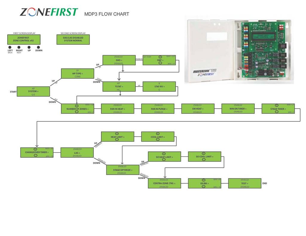
3 OPERATION The MDP3 can be controlled by conventional single stage or heat pump thermostats. Each thermostat can then call for heating, cooling or the fan. This panel can control single stage gas-oilelectric heating and cooling, two stage heating and cooling and most heat pumps. This panel can control two stage/speed and dual/fossil fuel heat pumps. When a call for either heating or cooling is made the panel keep open the damper(s) to the zone(s) calling, close the damper(s) to those zones not calling, activate the appropriate controls for heating or cooling, whichever is being called and not accept any calls for the opposite mode. Any calls for the opposite mode will be locked out until the initial mode is either satisfied or a period of time has elapsed that is sufficient for the first mode to satisfy, a maximum of 20 minutes. A unique sequence determines the time the unit has been running or needs to continue to run in order to adequately provide conditioning for each mode. If a particular mode has already been calling for 20 minutes or longer and an opposite call comes in the MDP3 will immediately drop the mode, enter the purge mode in order to dissipate the conditioned air into the zones calling before switching over to provide the new conditioning call to its zones. When using the MDP3 to control multi-stage stage heating or cooling, the stages are controlled based upon time after the first stage call from the thermostat. When any zone calls the panel s built-in timer begins and after the set period of time elapses the MDP3 will energize the second then the third stage heat (W2 & W3) or cool (Y2) output. The Stage Timer is adjustable between 5 to 21 minutes after the first stage calls. Once the second stage is on, it will continue to run until the call is satisfied and/or then cycle into the third stage of heat, if applicable, until call is satisfied. Once all zone thermostats are satisfied for heating and cooling, the MDP3 can now accept Fan calls allowing Continuous Air Circulation (CAC) in those zones where the thermostat s Fan Switch is set to ON. These zone dampers will be Open while the dampers to the zones where the Fan Switch is set to AUTO will be CLOSED. When all zone thermostats are satisfied for both Heating and Cooling, and all Fan switches are set to AUTO position, the HVAC unit will be off and all zone dampers will return to a normally open position. Once a zone calls for heating, cooling or fan, the dampers to the calling zones remain open and the dampers to the zones not calling will close. Menu Set-Up for Various HVAC Equipment (See Digital Menu Flow Guide, sheet 7) Most all of the MDP3 equipment set up options are available through its menu driven 2x16 character LCD. The MDP3 is factory set for conventional heating and cooling operation. The panel only needs to be configured when using with an electric furnace or heat pumps. Other functions come by wiring for specific applications. The following shows the most typical settings. Review each function for you application. SYSTEM G/E or HP This setting sets the HVAC Output operation. In G/E the Y1 makes as a Cool call and W1 as a Heat call. In HP position Y1 makes as the compressor call for both heating and cooling. HP Type CONV or FF This setting is used to determine the equipment output when the System is set to HP, this setting determines if the output will be for a conventional heat pump with electric back-up heat or fossil (dual) fuel mode. OAS (Outdoor Air Sensor) Enabled or Disabled The Outdoor Air Sensor is used only when using a heat pump with dual/fossil fuel back-up furnace. The OAS senses the outdoor air temperature and switches the heating control between the heat pump and the fossil fuel furnace. The temperature set point for the OAS is adjustable via the Menu setting OBP. It is adjustable from 5 F to 53 F. It is suggested that this be set just above freezing to avoid the heat pump from potentially going into Defrost mode. Enabled If the OAS senses the outdoor temperature is higher than the Outdoor Balance Point (OBP) setting the compressor will continue to run. If the outdoor temperature is lower than the OBP setting, the compressor will drop and the fossil fuel furnace will energize. When the OAS is enabled, the OAS temperature will be displayed on the MENU LCD. In the fossil fuel mode use of the OAS is optional. When the OAS is enable the Stag Optimization feature is no longer available. Disabled The heat pump will continue to run until heat call is satisfied or the emergency heat is activated via the thermostat or Menu setting EM Heat Enabled. Thermostat (TSTAT) HC or HP This setting determines if conventional Heat/Cool thermostats or Heat Pump thermostats are being used. Do not mix HC & HP stats, all stats used must be HC or HP. A conventional HC stat would have separate W and Y output for heating and cooling calls. A HP stat uses Y for both a heat and cool call and the O or B is used to determine whether the call is for Cooling (O) or Heating (B). STAT RV O or B When using HP type stats this setting determines if the O or B terminal (on stat) is wired to the W/OB terminal on the MDP3 to determine if the call if for Heat (B) or Cool (O). NUMBER OF ZONES This setting establishes the total (2-103) number of zones being used in the system. FAN IN HEAT Enabled or Disabled This setting will activates the Fan on a call for Heat in the Enabled position. In Disabled, the heating unit must activate the fan when the heat is called. 3
4 FAN IN PURGE Enabled or Disabled This setting determines if the Fan is kept on (Enabled) or off (Disabled) during the Purge Mode, after the end of each heat or cool call. The longer a call has been running up to 20 minutes, the shorter the wait time will be for an opposite call. If a call is over 20 minutes and an opposite call is made the changeover will be immediate following the purge time. This intelligent changeover timing makes the MDP3 unique to any other zoning system. PURGE TIMER The MDP3 has a built-in Purge Time after each call is satisfied and provides a minimum off time before another call is initiated. The Purge Time is set at 2 minutes after all calls for a particular mode are satisfied or when the Changeover Timer requires a changeover due to opposing calls. After all calls are satisfied or the changeover timer activates, the Purge Timer begins and the heating or cooling, whichever was on, is deactivated. Typically the fan may be running during this time and the damper(s) to the last zone(s) calling will remain open to purge the conditioned air only into those zones that were calling for the conditioning. The FAN IN PURGE setting may be Enabled to keep the fan running during the Purge mode in order to prevent the fan cycling off and back on between modes. In the instance where the fan staying on may create a draft, and the frequency of opposite calls is minimal, you may select the Disabled setting. EM HEAT Enabled or Disabled This setting establishes any heat call to call for the Emergency Heat. With this setting enabled EH RUNNING will scroll across the LCD and the Heat Status LED will flash (3x per second). This is used when there is no Emergency Heat selector on the thermostats. MINIMUM ON TIMER Enabled or Disabled The MDP3 has a minimum on time whenever the compressor operates in order to prevent frequent short cycling. Once there is a call for cooling or the compressor on a heat pump, the MDP3 will hold that call for a period of 2 minutes if this feature is Enabled. If Disabled is selected the minimum on timer feature is not operational. STAGE TIMER The MDP3 has a built-in stage timer that eliminates the need and added cost of using two stage thermostats. On a call for either heating or cooling the timer begins. Setting the Stage Timer via the MENU provides an adjustable time delay of 5 to 21 minutes between the first and second stage calls and the same between a second stage and third stage call of heating, if applicable. CHANGEOVER TIMER Whenever a call is made for either heating or cooling, the changeover timer is activated in order to track the amount of time heating or cooling is on. When an opposite call is made after a first call is existing the changeover timer calculates the amount of time the unit has already been supplying the first mode in order to determine how long it will hold off the opposite call. If an opposite call is made shortly after the first call, the opposite call may be held off for as much as 20 minutes. If the first call or subsequent calls for the first call mode has had that mode operating for up to 20 minutes already and an opposite call comes in after 20 minutes, the changeover timer will immediately recognize the opposite call, shutting off the current mode, enter the purge mode and automatically switch to the opposite mode. LAS (Leaving Air Sensor) Enabled or Disabled The Leaving Air Sensor, Model ZPS, is a remote sensor that is located in the supply air duct to sense the Leaving Air temperature of the HVAC Unit. The ZPS is a high limit protection for the heating and a low limit protection for the cooling. When zoning, the airflow through the HVAC Unit is critical. The ZPS protects the equipment in low air flow situations as well as when by-pass air is being directed back into the return air duct. The heating limit is adjustable from 110 F to 170 F. The cooling limit is adjustable from to 40 F to 50 F. When the LAS setting is Enabled the ZPS senses heating above its set point, or cooling below its set point, the MDP3 will drop all stages of heating or cooling. The ZPS must sense a 10 F fall for heating or rise for cooling before re-activating the first stages of heating or cooling. If multi stage heating or cooling is being used the stage timer will start again once the first stage is re-activated. When The LAS is Enabled the LAS temperature (example: LAS = 72 ) will be displayed on the MENU LCD. When LAS setting is Disabled the sensor has no impact on the operation of the MDP3. STAGE OPTIMIZE (SO) Enabled or Disabled The Stage Optimization setting uses the OAS adjustable temperature setting to control the function of bringing on additional stages of heating or cooling based on the outdoor temperature. SO HEAT LIMIT is adjustable from 0 F to 55 F SO COOL LIMIT is adjustable from 75 F to 90 F When SO is Enabled, if the OAS senses a temperature above the SO HEAT LIMIT additional stages of heating are locked out from energizing. If the OAS senses a temperature below the SO HEAT LIMIT additional stages of heating are energized based on the STAGE TIMER setting. If the OAS senses a temperature below the SO COOL LIMIT additional stages of cooling are locked out from energizing. If the OAS senses a temperature above the SO COOL LIMIT additional stages of cooling are energized bases on the STAGE TIMER setting. When SO is enabled the OAS is disabled in the Heat Pump, Fossil Fuel configuration setting. When SO is Disabled the sensor has no impact on staging of the MDP3. CENTRA - ZONE Enabled or Disabled The Zone 1 (Z1) thermostat is the master changeover point for all system calls. When Enabled the system is switched from heating, cooling and fan calls based on what the Z1 thermostat last called for. Once the Z1 stat calls for heating, all other zone stats can only call for heating and cooling calls are locked out. The Z1 stat must then call for cooling in order to switch the system to cooling, now the 4
5 other zones are able to call for cooling only and heat calls are locked out. Likewise, the Z1 stat must call for fan before the other zones may call for fan, heat and cool calls are locked out. When Enabled, CENTRA - ZONE will scroll across the MENU LCD. When Disabled the MDP3 returns to normal zoning operation HEAT LED is constantly illuminated RED when MDP3 is calling for the first stage of heating, will flash two times (2X) when second stage heat energizes and will flash three times (3X) when the third stage of heat or emergency heat is energized. COOL LED is constantly illuminated GREEN when the MPD3 is calling for the first stage of cooling and will flash two times (2X) when the second stage of cooling is energized. DS/BK The DS/BK terminal may be used with HVAC equipment that utilize a variable-speed blower fan. This setting signals the HVAC unit to reduce the blower speed. Connect the DS, BK, ODD or DHUM terminal on the HVAC equipment to this terminal. This output will provide 24vac when the percentage of zones calling is less than the user defined DS/BK operation setting. The DS/BK operation setting is adjustable from 10-50% in 5% increments. When the DS/BK terminal is energized, DS/BK will scroll across the MENU LCD. TEST Enabled or Disabled When this setting is Enabled all of the time delays on the MDP3 are accelerated to provide a quick test period. When Enabled the Power LED will flash and TEST will scroll across the MENU LCD. When Disabled the MDP3 resumes normal operation. ZONE-A-LONE The zone one thermostat becomes the controlling thermostat for the entire system. During long unoccupied periods, one thermostat (Z1) can be set back versus adjusting each zone thermostat on the system. All dampers are opened and all calls for heat, cool or fan are made from the zone one thermostat, all other zone thermostats are locked out. Normally Closed contacts: Zone-A-Lone is enabled Normally Open contacts : Resume normal zoning operations When Zone-A-Lone is enabled, ZONE-A-LONE will scroll the MENU LCD. CHECKOUT System checkout is accomplished through the use of the MENU LCD and the LED readouts that constantly indicate the system operation. The MENU LCD displays all controlled settings, adjustable or fixed. Displays LIMIT when heating or cooling temperature limits are reached, EM Heat when the system calls for it or the EM Heat setting is enabled, TEST when enabled, CENTA-ZONE when enabled, ZONE ALONE when the zone alone terminals are closed, DS/BK when the appropriate parameters allow the blower to slow down and OAS < OBP when the Outdoor Air Sensor detects temperatures below the defined Outdoor Balance Point setting. Also displays OAS & LAS F (OAS & LAS temperatures). FAN LED is constantly illuminated YELLOW when calling for the fan or when the compressor is running. ZONE DAMPER LEDs will constantly be illuminated GREEN when no zone is calling. When a zone calls for heating, cooling or fan that zone LED will remain illuminated and those zones not calling the LED will go out. WIRING The MDP3 is very simple to wire and requires only a minimum number of connections. The MDP3 terminal blocks are color coded and screw-less for all wires to be easily pushed into their respective terminal by de-pressing the button for each point and releasing once the wire is seated. (Solid wire can often just be pushed into the terminal without de-pressing the button.) To remove the wire, just press its button again and remove the wire. SENSORS: ZPS and OAS The ZPS and OAS (if used) each require two (2) wires to their respective LAS and OAS terminals on the H32P panel. Leaving Air Sensor In Supply Air Duct LAS LAS OAS OAS Outdoor Air Sensor only used with Fossil/Dual Fuel Applications Zone Dampers The MDP3 provides DC power to ZONEFIRSTs' exclusive Plug-In Zone Dampers. These dampers use and are supplied with a modular cord that is complete with RJ11 jacks on each end of a 25 cable for each zone damper. Up to 10 dampers can be wired to each zone. The panel has a GREEN LED to indicate when the damper should be open. Each damper motor has a two color LED that a positive indication of the damper being open or closed. When the LED is GREEN the damper is Open. When the LED is RED the damper is closed. POWER LED is constantly illuminated GREEN when 24VAC is applied to the MDP3. The power LED will flash green when the test mode is enabled. 5


6 ZONE DAMPER Zone Thermostats The thermostats wiring will be for Conventional single stage (Y-G-R-W-C) or Heat Pump (Y-G-R-E- C and O or B). See Wiring Diagram 1 and 2 each type of thermostat. WIRING DIAGRAM 1 Conventional Thermostats ZONE THERMOSTAT C W R Y G E G Y R W/OB C ZONE THERMOSTAT TERMINALS WIRING DIAGRAM 4 - HVAC Equipment Dual Fuel Heat Pump with Fossil Fuel Back-Up WIRING DIAGRAM 2 Heat Pump Thermostat ZONE THERMOSTAT C O/B R Y G E E G Y R W/OB C ZONE THERMOSTAT TERMINALS WIRING DIAGRAM 5 Single Speed Compressor Heat Pump WIRING DIAGRAM 3 - HVAC Equipment Up to Three Stage Heating and Two Stage Cooling 6


7 TROUBLESHOOTING The MDP3 is a very simple control to troubleshoot, especially with the LED indicators. The only other device needed is a simple Volt/Ohm meter. Almost all problems can be traced to an external component or wiring to the MDP3. The following procedures can help isolate the problem. Zone(s) Not Calling Each zone has a Green LED next to the zone relay when it is calling and that calling is being recognized by the MDP3. If a zone is supposed to be calling and the Zone LED is not on, check for 24VAC across the thermostat terminal C and the Y, if a Cool call, W if a Heat Call, or G if a Fan call. If there is no voltage here at the panel the panel is not getting the signal from the thermostat. The problem is mis-wiring, a broken wire or a problem in the thermostat. To check the zone on the panel, place jumper from R to Y, R to W or R to G to see that the panel is operating properly. WIRING DIAGRAM 6 Two Speed Compressor Heat Pump Zone(s) Will Not Shut Off If a zone will not stop calling, the Zone LED should still be on. Depending on the call disconnect the Y, W or G wire from the terminal strip. The zone will drop out. Check the thermostat wiring for a mis-wiring or short that keeps the zone calling. Damper Motor Checkout To checkout the dampers, the panel has a GREEN LED for each zone. This illuminates when the dampers are to be OPEN, either on a call or when all zones are satisfied. The damper position is confirmed by the bi-color LED on the motor. When the panel is Green, the motor LED must be Green also indicating the damper being open. When the panel LED is not lit the motor should be closed and this is confirmed by the damper LED being Red. 7
8 8
 ZoneFirst.com Shop Online at ZoneDampers.com fb.")
9 Copyright Trolex Corporation & ZoneFirst 20 Bushes Lane - Elmwood Park, NJ FirstZone ( ) ZoneFirst.com Shop Online at ZoneDampers.com fb.com/zonefirst 9
Digi-Zone Model MDP3 Ver.04
 Digi-Zone Model MDP3 Ver.04 Installation and Operating Instructions Controlling Your Comfort Room By Room System Indicator LEDs MDP3 Panel Features Power Indicator LED Leaving & Outdoor Air Sensors Zone
H32 Uni- Zone Model H32
 H32 Uni- Zone Model H32 Installation and Operating Instructions Controlling Your Comfort Room By Room F o l l o w u s o n H32 PANEL FEATURES System Mode Indicator LED Power Indicator LED HVAC Equipment
Installation and Operating Instructions
 MASTZON ZONIN SSTM 4 Zones For use with the 24V Damper Motors Model MZS4 Installation and Operating Instructions ontrolling our omfort oom By oom MASTZON ZONIN SSTM FATUS Purge Override Button System Mode
Model CZ-4. Installation and Operating Instructions. FORM White-Rodgers by Permission B
 Model Z-4 Installation and Operating Instructions FOM 2045-2 1306 2013 White-odgers by Permission 37-6864B Z-4 ZONIN SSTM FATUS Purge Override Button Adjustable Second Stage Timer System Mode Indicator
DIGI3U. Zoning Systems. Installation Guide. That s all we do. Three-Zone, Universal Controller for Gas/Electric or Heat Pump Applications
 Installation Guide DIGIU Three-Zone, Universal Controller for Gas/Electric or Heat Pump Applications -Zone Controller for the RNC Market Part #DMAN October 004 Zoning Systems That s all we do. INTRODUCTION
Safety & Installation Instructions
 Model 6303 & 6302 Zoned Comfort Control Safety & Installation Instructions READ AND SAVE THESE INSTRUCTIONS 61001212A 6302-6303 Zoned Comfort Control Install.indd 1 TABLE OF CONTENTS SAFETY INSTRUCTIONS..........................................
Safety & Installation Instructions
 Model 6203 & 6202 Zoned Comfort Control Safety & Installation Instructions READ AND SAVE THESE INSTRUCTIONS 61001213A 6202-6203 Zoned Comfort Control Install.indd 1 TABLE OF CONTENTS SAFETY INSTRUCTIONS..........................................
EnviroZone-4 & EnviroZone-2 Quick-Start Guide
 EnviroZone-4 & EnviroZone-2 Quick-Start Guide This guide is intended to give the installer a brief set of instructions about how to set up the FHP EnviroZone System. For more detailed information about
TZ-4 TotalZone Zone Control Panel
 TZ-4 TotalZone Zone Control Panel FEATURES PRODUCT DATA APPLICATION The TZ-4 TotalZone Zone Control Panel controls single-stage, multi-stage, conventional or heat pump heat/cool equipment. It controls,
LZP-2 ZONE CONTROL PANEL
 2004 Lennox Industries Inc. Dallas, Texas, USA ZONING SYSTEM 504,926M 5/2004 Litho U.S.A. LZP-2 ZONE CONTROL PANEL INSTALLATION INSTRUCTIONS FOR ZONE CONTROL PANELS USED WITH LENNOX HEATING AND COOLING
Zoning System for Residential Communicating, Variable Air Volume Heating/Cooling Systems
 PRODUCT SPECIFICATIONS ZONING IHARMONY Zoning System for Residential Communicating, Variable Air Volume Heating/Cooling Systems Bulletin No. 20663 November 207 Supersedes August 205 COMPONENTS AND EQUIPMENT
Installation Instructions
 T2 -PAC01 -A, T2 -NAC01 -A T2 -PHP01 -A, T2 -NHP01 -A LEGACYt SERIES THERMOSTATS Installation Instructions A07047 Legacy Series Programmable Thermostat A07046 Legacy Series Non-Programmable Thermostat
1F98EZ-1421, Easy Install
 1F98EZ-1421, -1441 Easy Install For up to 4 Stages and 2 Stages Cool INSTALLATION INSTRUCTIONS APPLICATIONS Configuration Options Single Stage Multi Stage Pump Pump with Dual Fuel FAILURE TO READ AND FOLLOW
OPERATION INSTRUCTIONS DEMAND DEFROST CONTROL BOARD MODEL FOR USE WITH MODELS: AFFINITY, ECHELON, ACCLIMATE HEAT PUMP SERIES
 OPERATION INSTRUCTIONS DEMAND DEFROST CONTROL BOARD MODEL 500644 FOR USE WITH MODELS: AFFINITY, ECHELON, ACCLIMATE HEAT PUMP SERIES A047-001 FIGURE 1: Demand Defrost Control Module ANTI-SHORT CYCLE DELAY
Advanced Installation and Configuration Instructions
 TP-WEM01-A Performance Series AC/HP Wi- Fi Thermostat Carrier Côr Thermostat Advanced Installation and Configuration Instructions Table of contents How to Use This Document... 3 Wiring Diagrams... 4 Installations
INSTALLATION MANUAL. * If using remote sensors the thermostat must be hardwired. Need Help?
 INSTALLATION MANUAL This manual covers the following models: T955W Master Thermostat Base Module Thermostat Applications Guide Description Gas or Oil Heat Electric Furnace Heat Pump (No Aux. or Emergency
TH146-N-2H1C. 1. Introduction. 2. Installation. 1.1 Applications. 2.1 Control Module (CT280-2H1C) 1.2 Supplied Parts. 1.
 1.2 Supplied Parts. 1.") TH146-N-2H1C Installation Guide Non-programmable H/C Controller Removable Connector * Removable Connector * TH146 User Console CT280-2H1C Control Module AC144-03 Outdoor Temperature Sensor * To remove
TH146-N-2H1C Installation Guide Non-programmable H/C Controller Removable Connector * Removable Connector * TH146 User Console CT280-2H1C Control Module AC144-03 Outdoor Temperature Sensor * To remove
Installation and Setup Guide
 Installation and Setup Guide Color Touchscreen Programmable Commercial Thermostat ComfortSense 7500 Model: C0STAT06FF1L Cat: 13H15 507506-01 3/2016 Supersedes 10/2015 Table of Contents Shipping and Packing
TH146-P-2H1C. 1. Introduction. 2. Installation. 1.1 Applications. 2.1 Control Module (CT280-2H1C) 1.2 Supplied Parts. 1.
 1.2 Supplied Parts. 1.") TH146-P-2H1C Installation Guide Programmable 2H1C Controller Removable Connector * Removable Connector * TH146-P User Console CT280-2H1C Control Module AC144-03 Outdoor Temperature Sensor * To remove a
TH146-P-2H1C Installation Guide Programmable 2H1C Controller Removable Connector * Removable Connector * TH146-P User Console CT280-2H1C Control Module AC144-03 Outdoor Temperature Sensor * To remove a
Commercial Touchscreen Thermostat
 55,13M 1/27 Supersedes 12/25 Commercial Touchscreen Thermostat 25 Lennox Industries, Inc. Dallas, Texas, USA APPLICATION Page 1 INSTALLATION INSTRUCTIONS The Lennox Commercial Touchscreen Thermostat provides
Safety & Installation Instructions
 Premium Programmable Thermostat Safety & Installation Instructions Model 8570 READ AND SAVE THESE INSTRUCTIONS TABLE OF CONTENTS PAGE SPECIFICATIONS............................. 1 WIRE REQUIREMENTS.........................
T-32-TS Touchscreen Thermostat. Installation Manual
 T-32-TS Touchscreen Thermostat Installation Manual TABLE OF CONTENTS Introduction...4 Getting Started...5 Installing the Thermostat...6, 8 Disassembly...6 Thermostat Location...6 Mounting the Subbase...6,
ZonexCommander. ZonexCommander(Plus) Installation and Applications Manual. Network All Your HVAC Equipment
 Installation and Applications Manual. Network All Your HVAC Equipment") ZonexCommander ZonexCommander(Plus) Network All Your HVAC Equipment Centralized DDC Communications for Stand-Alone HVAC and Zoned Systems Installation and Applications Manual Part #ZCMAN Rev. Oct 2014
ZonexCommander ZonexCommander(Plus) Network All Your HVAC Equipment Centralized DDC Communications for Stand-Alone HVAC and Zoned Systems Installation and Applications Manual Part #ZCMAN Rev. Oct 2014
Emerson Inspire 1HDEZ Installation Instructions. Thermostat/Interface Equipment Control TROUBLESHOOTING
 Emerson Inspire 1HDEZ-1521 Installation Instructions Thermostat/Interface Equipment Control TROUBLESHOOTING FAILURE TO READ AND FOLLOW ALL INSTRUCTIONS CAREFULLY BEFORE INSTALLING OR OPERATING THIS CONTROL
VisionPRO 8000 with Wi-Fi
 VisionPRO 8000 with Wi-Fi FEATURES PRODUCT DATA Thermostat acquires weather data through either a wired sensor or an Internet connection, making for a truly universal installation. U1 Terminals One set
Smart Temp. Model
 Smart Temp Model 42-160 SINGLE STAGE PROGRAMMABLE THERMOSTAT 1 Heat / 1 Cool Single Stage Thermostat. 5+2 Programmable, Compatible with Gas Heat & Heat Pump System Installation and Operation Manual SPECIFICATIONS:--------------------------------------------------------------------------------
Verasys System Operation Overview Technical Bulletin
 Contents subject to change. Verasys System Operation Overview Technical Bulletin Code No. LIT-12012370 Issued January 2016 Refer to the QuickLIT Web site for the most up-to-date version of this document.
York 25-Ton VAV Rooftop Unit
 HVAC PRO for Windows User s Manual 637.5 OEM Section Technical Bulletin Issue Date 0996 York 25-Ton VAV Rooftop Unit Introduction Page 3 Overview *3 Configuration 5 Sequence of Operation 7 Modes of Operation
WARNING IMPORTANT. iharmony Zoning System CONTROLS KITS AND ACCESSORIES. Installation Instructions for the iharmony Zoning System (10C16)
") CONTROLS KITS AND ACCESSORIES 2016 Lennox Industries Inc. Dallas, Texas, USA 9/2016 Supersedes11/2015 iharmony Zoning System Installation Instructions for the iharmony Zoning System (10C16) WARNING Improper
CONTROLS KITS AND ACCESSORIES 2016 Lennox Industries Inc. Dallas, Texas, USA 9/2016 Supersedes11/2015 iharmony Zoning System Installation Instructions for the iharmony Zoning System (10C16) WARNING Improper
Ventilation Products AirCycler g2/g2-k Installation & User s Guide
 Ventilation Products AirCycler g2/g2-k Installation & User s Guide VENTILATION MADE BREEZY! a breeze to install a breeze to use INTRODUCTION If the AirCycler g2 was installed in your home as a ventilation
Safety & Installation Instructions
 Model 8800 Universal Communicating Thermostat Safety & Installation Instructions READ AND SAVE THESE INSTRUCTIONS Table of contents Installation Installation location recommendations... 2 Thermostat mounting...
Installer Guide. WARNING Important Safety Information. 1 Specifications
 1 Specifications cont. Premier Series Universal Auto Changeover Up to 3 Heat / 2 Cool Heat Pump or 2 Heat / 2 Cool Conventional Thermostat Installer Guide Before Installing, Programming or Operating, PLEASE
INSTALLATION MANUAL. This manual covers TopTech models: TT-S-755H. Need Help? Thermostat Applications Guide. Power Type. Table of Contents.
 INSTALLATION MANUAL This manual covers TopTech models: TT-S-755H Thermostat Applications Guide Description Gas or Oil Heat Electric Furnace Heat Pump (No Aux. or Emergency Heat) Heat Pump (with Aux. or
QUICK REFERENCE GUIDE P.C. BOARD/WALL THERMOSTAT FOR 6535D, 6537C, 6538 A&B SERIES TWO TON PACKAGED HIGH EFFICIENCY HEAT PUMPS
 QUICK REFERENCE GUIDE P.C. BOARD/WALL THERMOSTAT FOR 6535D, 6537C, 6538 A&B SERIES TWO TON PACKAGED HIGH EFFICIENCY HEAT PUMPS RV Products A Division of Airxcel, Inc. P.O. Box 4020 Wichita, KS 67204 1-316-832-4357
ZonexCommander. ZonexCommander(Plus) Installation and Applications Manual. Network All Your HVAC Equipment
 Installation and Applications Manual. Network All Your HVAC Equipment") ZonexCommander ZonexCommander(Plus) Network All Your HVAC Equipment Centralized DDC Communications for Stand-Alone HVAC and Zoned Systems Installation and Applications Manual Part #ZCMAN Rev. July 2010
ZonexCommander ZonexCommander(Plus) Network All Your HVAC Equipment Centralized DDC Communications for Stand-Alone HVAC and Zoned Systems Installation and Applications Manual Part #ZCMAN Rev. July 2010
Installation Instructions
 P700U -21NHP Base Non -Programmable Thermostats Installation Instructions Designed and Assembled in the USA. US patents: US20060165149 A1, USD578026 SI, US6205041 B1 A14005 Base Non---Programmable Thermostat
SAS6000UTK-7-WIFI OPERATING INSTRUCTION
 SAS6000UTK-7-WIFI OPERATING INSTRUCTION 1 This manual apply for SAS6000UTK-7-WIFI,used with Single Stage,Multi-Stage,Heat pump and has mobile control function. SPECIFICATION Power Supply Dual Power 24VAC
AirCycler g2-k Installation & User s Guide
 SIMPLE VENTILATION SOLUTIONS AirCycler g2-k Installation & User s Guide VENTILATION MADE BREEZY! a breeze to install a breeze to use TABLE OF CONTENTS AirCycler g2-k Introduction Safety Considerations
Comfort System T-21-P Touchscreen Thermostat Installation Manual
 Comfort System T-21-P Touchscreen Thermostat Installation Manual Version 1.40 INTRODUCTION The Comfort System T-21-P is a feature-rich touchscreen thermostat that can be battery powered or hardwired to
SmartZone TM System Manual
 SmartZone TM System Manual Rev C3 June 1, 2007 Page 0 of 21 Table of Contents SmartZone TM System Manual Rev C3. April 23, 2007 Introduction..2 o Why Use Residential Zoning?..2 Architectural Challenges...
CONTROLS THERMOSTATS Bulletin No November 2001 Supersedes September 2001 INNOVATOR PROGRAMMABLE THERMOSTATS ENGINEERING DATA
 ENGINEERING DATA CONTROLS THERMOSTATS Bulletin No. 210125 November 2001 Supersedes September 2001 INNOVATOR PROGRAMMABLE THERMOSTATS L21 SERIES THERMOSTATS HEAT/COOL SYSTEMS Features (All Models): Extra
Ventilation Products AirCycler g2/g2-k Installation & User s Guide
 Ventilation Products AirCycler g2/g2-k Installation & User s Guide VENTILATION MADE BREEZY! a breeze to install a breeze to use INTRODUCTION If the AirCycler g2 was installed in your home as a ventilation
CommStat 6. Controller for Redundant HVAC Systems PRODUCT DATA SHEET
 CommStat 6 Controller for Redundant HVAC Systems PRODUCT DATA SHEET General Description The CommStat 6 HVAC controller is designed for controlling up to six redundant air conditioners in an E-House or
Installation Guide ProR221J, ProR212J, ProR321J and ProR312J
 ProZone I n t e l l i g e n t Z o n i n g Zones See table below. ompatible Equipment All panels operate with gas/electric systems, conventional heat pumps and dual fuel heat pumps. Equipment Selection
Safety & Installation Instructions
 8400 Series Thermostats Safety & Installation Instructions READ AND SAVE THESE INSTRUCTIONS 61000652C 8400 Tstat Install.indd 1 10/13/09 11:08:56 AM Table of contents Installation Installation location
Installation Instructions / User s Manual TSTAT0406 and TSTAT0408
 997-060180-5 Installation Instructions / User s Manual TSTAT0406 and TSTAT0408 4 HEAT 2 COOL DUAL FUEL TSTAT0406 & TSTAT0408-4 WIRE CAPABLE THERMOSTAT (NAXA00201DB Daughter Board sold separately) LEFT
Preface. Overview. The above illustration shows a typical three zone Aprilaire Zoned Comfort Control system.
 Owner s Manual Preface Thank you for purchasing a new Aprilaire Zoned Comfort Control System. We sincerely appreciate your business and are pleased to add your name to our growing list of customers. With
HEAT HEAT HEAT COOL COOL
 OWNER S MANUAL AUTO 74 COOL 7 2 HEAT T O T A L I N E HEAT COOL COMMERCIAL THERMOSTAT P/N P374-2700 HEAT PUMP NON-PROGRAMMABLE DIGITAL THERMOSTAT 3 Configurable Outputs Control up to 2 Heat & 2 Cool Stages
INSTALLATION INSTRUCTIONS TEC40 ELECTRONIC CONTROLLER
 INSTALLATION INSTRUCTIONS TEC40 ELECTRONIC CONTROLLER BARD MANUFACTURING COMPANY Bryan, Ohio 43506 Since 1914...Moving ahead, just as planned. Manual: 2100-393C Supersedes: 2100-393B File: Volume III Tab
SAS6000UTK-7 UNIVERSAL THERMOSTAT
 SAS6000UTK-7 UNIVERSAL THERMOSTAT Used with Single Stage, Multi-Stage, Heat pump Installation and operation instructions SPECIFICATION: Power Supply Dual Power 24VAC (18-30VAC,50/60Hz) or Battery Powered
Installation and Advanced Programming Instructions. HP8211-1RJ and HP8321-1RJ Heat Pump Thermostats
 Installation and Advanced Programming Instructions HP8211-1RJ and HP8321-1RJ Heat Pump Thermostats These instructions are intended for installation and first time set up of the thermostat. For day to day
Document # R01
 Viconics VT7600 Series PIR-Ready Rooftop Unit Controllers Part 1 General The VT7600 series is designed for single-stage and multi-stage control of heating/cooling equipment such as rooftop and self-contained
FP EZ4F 4 Zone Controller
 4 Zone Controller READ THIS GUIDE BEFORE INSTALLING CONTROLLER Zone Controller Installa on and Start up Guide Rev 20170801 Ver 16 Input Ra ngs: Voltage: 18 40 VAC 50/60 HZ transformer of 40 VA or more
T7200D,E Series 2000 Commercial Microelectronic Thermostats
 T7200D,E Series 2000 Commercial Microelectronic Thermostats INSTALLATION INSTRUCTIONS APPLICATION The T7200D,E Thermostats provide electronic control of 24 Vac commercial single-zone heating, ventilating
INSTALLATION & OPERATION MANUAL
 INSTALLATION & OPERATION MANUAL Model TME- * * Balance of model number is determined by customer specifi ed limits and Setbacks. AUTOMATIC SETBACK THERMOSTAT LIGHT SENSING OR CONTACT CLOSURE FOR LOW VOLTAGE
1F Day 5/1/1 Day Non-Programmable. W/ Economizer Max. Stage Heat/Cool 1/1 1/2 2/2 2/3 3/1 3/2 4/2 4/3
 Save these instructions for future use! FAILURE TO READ AND FOLLOW ALL INSTRUCTIONS CAREFULLY BEFORE INSTALLING OR OPERATING THIS CONTROL COULD CAUSE PERSONAL INJURY AND/OR PROPERTY DAMAGE. APPLICATIONS
CommStat 4. Controller for Redundant Telecom HVAC Systems PRODUCT DATA SHEET. Features and Benefits
 CommStat 4 PRODUCT DATA SHEET Controller for Redundant Telecom HVAC Systems General Description The CommStat 4 is an HVAC controller designed specifically for controlling two redundant air conditioners,
INSTALLATION INSTRUCTIONS
 INSTALLATION INSTRUCTIONS TEC40 ELECTRONIC CONTROLLER Bard Manufacturing Company, Inc. Bryan, Ohio 43506 www.bardhvac.com Manual: 200-393O Supersedes: 200-393N Date: 2-26-6 Page of 8 CONTENTS Shipping
Safety & Installation Instructions
 8400 Series Thermostats Safety & Installation Instructions READ AND SAVE THESE INSTRUCTIONS 61000652A 8400 Tstat Install.indd 1 7/23/09 2:20:45 PM Table of contents Installation Installation location recommendations...
Wiring: All wiring should be conventional 18 gauge thermostat wire. Thermostats and zone dampers may be located up to 300 feet from the Z-300 panel.
 THE EEN Z NE Z EE THE NE N Sequence of Operation: The reen Zone Z-300-HPS is a residential / light commercial zone control system that allows a single HVA unit to have up to three separate zones. Each
INSTALLATION MANUAL. This manual covers TopTech models: TT-N-851. Need Help? Power Type. Thermostat Applications Guide. Page.
 INSTALLATION MANUAL This manual covers TopTech models: TT-N-851 Thermostat Applications Guide Description Gas or Oil Heat Electric Furnace Heat Pump (No Aux. or Emergency Heat) Heat Pump (with Aux. or
Installer Guide. WARNING Important Safety Information. 1 Specifications
 1 Specifications cont. Premier Series Universal Auto Changeover Up to 3 Heat / 2 Cool Conventional and Heat Pump Thermostat Installer Guide Before Installing, Programming or Operating, PLEASE READ ALL
CXM/DXM. Application, Operation & Maintenance Instructions 97B0003N08 Revision: 01/10/05. CXM/DXM Digital Heat Pump Controllers.
 CXM/DXM CXM/DXM Digital Heat Pump Controllers Application, Operation & Maintenance Instructions 97B0003N08 Revision: 01/10/05 Table of Contents CXM / DXM Control Features Comparison 2 Part I - CXM Control
Auto-Changeover: Cool Setpoint: Deadband: Dehumidify: Differential: Heat Setpoint: Humidify: Icon: Mode: Non-Programmable Thermostat:
 SM CAUTION Follow the Installation Instructions before proceeding. Set the thermostat mode to OFF prior to changing settings in setup or restoring Factory Defaults. This Explorer thermostat has the ability
Zoning System Design Manual
 Zoning Made Effortless 70-2321-03 Introduction The Concept of Zoning The basic principle of forced air zoning is to allow one HVAC system to be controlled by multiple thermostats, heating and cooling a
INSTALLATION MANUAL. Need Help? This manual covers the following models: T755. Power Type. Thermostat Applications Guide. Page.
 INSTALLATION MANUAL This manual covers the following models: T755 Thermostat Applications Guide Description Gas or Oil Heat Electric Furnace Heat Pump (No Aux. or Emergency Heat) Heat Pump (with Aux. or
QUICK REFERENCE GUIDE P.C. BOARD/WALL THERMOSTAT FOR 6536A891, 6536B891 & 6536C891 TWO TON PACKAGED HEAT PUMPS
 QUICK REFERENCE GUIDE P.C. BOARD/WALL THERMOSTAT FOR 6536A891, 6536B891 & 6536C891 TWO TON PACKAGED HEAT PUMPS Note: This manual may also be used for 6536-871 series heat pumps if the 6535-3209 Replacement
CONTENTS. Installation Guide. VT7200 Series
 VT7200 Series Installation Guide For mercial HVAC Applications November 2015 CONTENTS Installation 2 Location 2 Installation 2 Configurable BI/UI inputs overview 4 Network ready 6 Terminal, Identification
WARNING Important Safety Information
 1 Specifications Premier Series Non-Programmable Thermostats MODEL 3000 MODEL 3200 1 2 3 4 5 Specifications Installation Testing Your New Thermostat Programming User Settings Temperature Adjustment WARNING
1F Day 5/1/1 Day Non-Programmable. W/ Economizer Max. Stage Heat/Cool 1/1 1/2 2/2 2/3 3/1 3/2 4/2 4/3
 Save these instructions for future use! FAILURE TO READ AND FOLLOW ALL INSTRUCTIONS CAREFULLY BEFORE INSTALLING OR OPERATING THIS CONTROL COULD CAUSE PERSONAL INJURY AND/OR PROPERTY DAMAGE. APPLICATIONS
Model 1750A/ 1770A Dehumidifier Installation Instructions
 Model 1750A/ 1770A Dehumidifier Installation Instructions Safety Instructions WARNING 1. Improper installation may cause property damage or injury. Installation, service, and maintenance must be performed
WARNING Important Safety Information
 Builder Series Non-Programmable Thermostats MODEL 1000 MODEL 0 1 2 3 4 Single Stage Heat / Cool Conventional and Heat Pump Multi-Stage 2 Heat / 1 Cool Conventional and Heat Pump Before Installing, Programming
Small Digital Thermostat Controller Temperature Control
 www.klimaireintl.com Small Digital Thermostat Controller Temperature Control Small-Fiac IOM Manual KLIMAIRE International +1.647. 477. 3333 +1.646. 808. 0240 klimaireintl@klimaireintl.com Digital Thermostat
OPERATING INSTRUCTIONS
 COMFORT CONTROL CENTER 2 THERMOSTAT OPERATING INSTRUCTIONS PROGRAMMABLE THERMOSTAT MODEL 3314080.000 BLACK 3314080.015 WHITE USA SERVICE OFFICE Dometic Corporation 1120 North Main Street Elkhart, IN 46514
CommStat 4 Controller
 CommStat 4 Controller CommStat 4 Telecom HVAC Controller The CommStat 4 is an HVAC controller designed specifically for controlling two redundant air conditioners, heat pumps and air conditioners with
WARNING Important Safety Information
 1 Specifications Premier Series Non-Programmable Thermostats MODEL 3000 MODEL 3200 1 2 3 4 Specifications Installation Testing Your New Thermostat Programming User Settings WARNING Important Safety Information
SPECIFICATIONS for AIR CONDITIONING CONTROLLER ZONE CONTROL
 SPECIFICATIONS for AIR CONDITIONING CONTROLLER ZONE CONTROL 1. INTROUCTION Zone control is a two pieces fan coil thermostat available for Heat/Cool versions. Its application is for the duct type system
THERMOSTATS 126. MECHANICAL THERMOSTATS 1C20 / 1C21 / 1C26 / 1E30 / 1E56 / 1F56... Wiring Diagrams / Configuration
 INDEX THERMOSTATS 126 l (s) Description Page(s) EMERSON BI BLUE 12" TOUCHSCREEN 1F97-1277... Wiring Diagrams / Configuration... 126 131 1F95-1280 / 1F95-1291... Wiring Diagrams / Configuration... 128 131
Model DEHXXCDA1070 & DEHXXCDA1095 Dehumidifier Installation Instructions
 Model DEHXXCDA1070 & DEHXXCDA1095 Dehumidifier Installation Instructions Safety CONSIDERATIONS Improper installation, adjustment, alteration, service, maintenance, or use can cause explosion, fire, electrical
Marvel S MICROPROCESSOR CONTROLLER. Installation, Operation and Maintenance Manual Effective October 2018 DISCONTINUED. For Reference Only
 Marvel S MICROPROCESSOR CONTROLLER Installation, Operation and Maintenance Manual Effective October 2018 DISCONTINUED For Reference Only ***Interactive PDF*** Contents General Purpose...3 Standard And
A complete product line to fi t all your application needs GENERAL PRODUCT FEATURES
 Electro-HELPS I PLENUM HEATERS A complete product line to fi t all your application needs The Electro-Mate has been heating America s homes and businesses since 1979. We take pride in our craftsmanship
CP-6 Installation and Operation Instructions 3 Heat / 2 Cool Heat Pump with Fossil Fuel option Auto Changeover - Cooling Priority or Majority Wins
 P-6 Installation and Operation Instructions 3 Heat / 2 ool Heat Pump with Fossil Fuel option Auto hangeover - ooling Priority or Majority Wins Sequence of Operation: Each zone damper is controlled by its
Programmable Touchscreen Thermostats. Disconnect power before beginning installation.
 Installer Guide Touchscreen Programmable Touchscreen Thermostats 6100 Single Stage Heat / Cool Conventional or Heat Pump 6300 Up to 4 Heat / 2 Cool Heat Pump Up to 3 Heat / 2 Cool Conventional 6400 Up
Installation Instructions
 TB --- PAC01 --- A TB --- PHP01 --- A Base Series Programmable Thermostats Installation Instructions Designed and Assembled in the USA. US patents: US20060165149 A1, USD578026 SI, US6205041 B1 A07107 Base
TZ-3 TotalZone Zone Control Panel
 TZ-3 TotalZone Zone Control Panel FEATUES PODUCT DATA APPLICATION The TZ-3 TotalZone Zone Control Panel controls single-stage, multi-stage, conventional or heat pump heat/cool equipment. It controls 2
Installation & Operation Instructions
 Installation & Operation Instructions Installation Precautions This Zoning System must be installed by a qualified HVAC Contractor! Caution - Electrical Hazard Can cause personal injury or equipment damage.
icomfort Residential Communicating Control System icomfort Touch Communicating Thermostat
 C O N T R O L S icomfort Residential Communicating Control System icomfort Touch Communicating Thermostat P R O D U C T S P E C I F I C AT I O N S Bulletin No. 210538 March 2012 Supersedes October 2011
T7300F Series 2000 Commercial Microelectronic Conventional or Heat Pump Thermostat
 T7300F Series 2000 Commercial Microelectronic Conventional or Heat Pump Thermostat INSTALLATION INSTRUCTIONS APPLICATION The T7300F Thermostat provides electronic control of 24 Vac commercial single zone
T8611G Chronotherm Deluxe Zoning Heat Pump Thermostat
 T8611G Chronotherm Deluxe Zoning Heat Pump Thermostat INSTALLATION INSTRUCTIONS APPLICATION The T8611G Chronotherm Deluxe Zoning Heat Pump Thermostat provides electronic control of 24 Vac zoned heat pump
Smart Temp. ApolloP/n Installation Manual. Version 1.0
 Smart Temp ApolloP/n 44-800 Installation Manual Version 1.0 TABLE OF CONTENTS Introduction...6 Getting started...7 Installing the thermostat...8 Disassembly...8 Thermostat location...8 Mounting the subbase...8,
PRO Installation. Thermostat Wi-Fi
 PRO Installation Thermostat Wi-Fi 1 Designed by the pros for the pros There are a lot of choices when it comes to buying a thermostat, but only one combines 125 years of experience and the latest connected
THERMOSTATS. 100-Series. 200-Series. 300-Series. 400-Series. 500-Series. Model Number Identification UHC TST 101 GE MS
 FORM NO. T22-001 REV. 6 Supersedes Form No. T22-001 Rev. 5 THERMOSTATS 100-Series NON-PROGRAMMABLE UHC-TST101GESS UHC-TST102HPMS UHC-TST103UNMS 200-Series PROGRAMMABLE UHC-TST201GESS UHC-TST202HPMS UHC-TST203UNMS
Daikin ENVi Thermostat installation overview
 Daikin ENVi Thermostat installation overview RESIDENTIAL LIGHT COMMERCIAL COMMERCIAL Presenter s Name Presenter s Title Daikin ENVi system overview (web based thermostat) Slide 2 Daikin ENVi System Overview
WARNING Important Safety Information
 Premier Series Programmable Thermostats MODEL 5200 1 2 3 4 5 Specifications Installation Programming Installer Settings Testing Your New Thermostat Programming User Settings WARNING Important Safety Information
INSTALLATION INSTRUCTIONS
 INSTALLATION INSTRUCTIONS MC3000 SERIES SOLID STATE DUAL UNIT LEAD/LAG CONTROLLER Bard Manufacturing Company Bryan, Ohio 43506 Since 1914...Moving ahead, just as planned. Manual No.: 2100-452 Supersedes:
Specifications and Performance
 R45C/H Packaged Terminal Air Conditioner (PTAC) Packaged Terminal Heat Pump (PTHP) Straight Cooling Nominal Capacities 9,000 12,000 15,000 18,000 Btuh The Right Fit for Comfort 2.6 3.5 4.4 5.3 kw Heat
Digital Precise Air Control - DPAC
 Digital Precise Air Control - DPAC Mode Enable Sensor Options The temperature of this sensor will determine if the unit is in heating, cooling or vent mode during Occupied operation. The following options
INSTALLER'S SYSTEM SETUP GUIDE NOTICE
 2014 Lennox Industries Inc. Dallas, Texas, USA INSTALLER'S SYSTEM SETUP GUIDE Thermostat Touch Screen Programmable Communicating Thermostat Thermostat NOTICE Web and Mobile Apps Read this manual before
1F Non-programmable Electronic Digital Heat Pump Thermostat INSTALLATION AND OPERATION INSTRUCTIONS
 FAILURE TO READ AND FOLLOW ALL INSTRUCTIONS CAREFULLY BEFORE INSTALLING OR OPERATING THIS CONTROL COULD CAUSE PERSONAL INJURY AND/OR PROPERTY DAMAGE. DESCRIPTION Your new White-Rodgers Digital Thermostat
WARNING Important Safety Information
 Premier Series Programmable Thermostats MODEL 5000 1 2 3 Specifications Installation Testing Your New Thermostat Programming User Settings WARNING Important Safety Information Additional Operation Features