EQ SERIES High Performance Commercial Pump
|
|
|
- Beatrix Gallagher
- 5 years ago
- Views:
Transcription
1 EQ SERIES High Performance Commercial Pump Installation and User's Guide IMPORTANT SAFETY INSTRUCTIONS READ AND FOLLOW ALL INSTRUCTIONS SAVE THESE INSTRUCTIONS
2 Technical and Customer Support (Europe) For technical support questions and product service information, contact: Phone: (0032) A.M. to 5 P.M. (GMT) Fax: (0032) Technical and Customer Support (United States) For technical support questions and product service information, contact: Sanford, North Carolina (8 A.M. to 5 P.M. - EST) Moorpark, California (8 A.M. to 5 P.M. - PST) Phone: (800) Fax: (800) and staritepool.com CE marking only applies to 50 Hz models: EQK300, EQK500, EQK750, and EQK1000. ETL marking only applies to models: EQW300-1PH and EQW500-1PH Pentair Water Pool and Spa, Inc. All rights reserved. This document is subject to change without notice Hawkins Ave., Sanford, NC (919) West Los Angeles Ave., Moorpark, CA (805) The Pentair Pool Products logo and EQ Series are registered trademarks of Pentair Water Pool and Spa, Inc. Other trademarks and trade names may be used in this document to refer to either the entities claiming the marks and names or their products. Pentair Water Pool and Spa, Inc. disclaims any proprietary interest in trademarks and trade names other than its own. P/N Rev. G 06/26/07
3 i Table of Contents Important Safety Precautions... ii Section 1: Introduction...1 EQ Series Pump Overview...1 General Features... 2 Section 2: Installation...3 Installing the EQ Series Pump... 3 Mechanical Installation...3 Pressure Testing... 5 Section 3: Electrical Requirements... 7 Electrical Requirements and Field Wiring... 7 Section 4: Initial Operation of Pump...9 Priming the EQ Series Pump... 9 Section 5: Maintenance Cleaning the Strainer Basket Preventative Maintenance Section 6: Servicing Disassembling Assembling...15 Section 7: Troubleshooting Section 8: Replacement Parts Section 9: Pump Technical Data Pump Curves Engineering Specifications...19 Dimensional Data... 20
4 ii IMPORTANT SAFETY PRECAUTIONS Important Notice: This guide provides installation and operation instructions for the EQ Series Pump. Consult Pentair Water with any questions regarding this equipment. Attention Installer: This guide contains important information about the installation, operation and safe use of this product. This information should be given to the owner and/or operator of this equipment after installation or left on or near the pump. Attention User: This manual contains important information that will help you in operating and maintaining this pump. Please retain it for future reference. WARNING Before installing this product, read and follow all warning notices and instructions which are included. Failure to follow safety warnings and instructions can result in severe injury, death, or property damage. Call (800) (US) or (Europe) for additional free copies of these instructions. Consumer Information and Safety The EQ Series pumps are designed and manufactured to provide many years of safe and reliable service when installed, operated and maintained according to the information in this manual and the installation codes referred to in later sections. Throughout the manual, safety warnings and cautions are identified by the symbol. Be sure to read and comply with all of the warnings and cautions. DANGER Risk of electrical shock or electrocution. This pool pump must be installed by a licensed or certified electrician or a qualified pool serviceman in accordance with the National Electrical Code and all applicable local codes and ordinances. Improper installation will create an electrical hazard which could result in death or serious injury to pool users, installers, or others due to electrical shock, and may also cause damage to property. Always disconnect power to the pool pump at the circuit breaker before servicing the pump. Ensure that the disconnected circuit is locked out or properly tagged so that it cannot be switched on while you are working on the pump. Failure to do so could result in serious injury or death to serviceman, pool users or others due to electric shock. WARNING Do not operate the pump until you have read and understand clearly all the operating instructions and warning messages for all equipment that is a part of the pool circulating system. The following instructions are intended as a guide for initially operating the pump in a general pool installation, however each installation may have unique conditions where the starting procedure could be different. Failure to follow all operating instructions and warning messages can result in property damage or severe personal injury or death.
5 iii IMPORTANT SAFETY PRECAUTIONS (continued) WARNING WARNING CAUTION Never exceed the maximum operating pressure or temperature limits of the system components. Pumps installed with the EQ Strainer Pot Assembly should not be tested at a pressure that exceeds the value written on the EQ Strainer Pot. See the Owner's Manual that accompanies that product for more instructions. Ensure that pressures higher than those required in the pressure test cannot inadvertently be applied to the circulation system. This may require the use of a pressure regulator between the water supply and the circulation system. Changes in temperature or barometric pressure can cause the internal test pressure to increase or decrease over time once the system is isolated. A pressure relief device should be installed that would prevent the pressure from exceeding the intended test pressure. Exceeding these limits could result in a component failing under pressure. This instantaneous release of energy can cause failed components to be accelerated to high velocities and to travel distances of 100 feet or more. These components could cause severe personal injury or death if they were to strike a person. Due to the potential risk that can be involved it is recommended that the pressure test be kept to the minimum time required by the local code. Do not allow people to work around the system when the circulation system is under pressure test. Post appropriate warning signs and establish a barrier around the pressurized equipment. If the equipment is located in an equipment room, lock the door and post a warning sign. Never attempt to adjust any closures or lids or attempt to remove or tighten bolts when the system is pressurized. These actions can result in a separation or failure of system components. This instantaneous release of energy can cause components to be accelerated to high velocities and to travel distances of 100 feet or more. These components could cause severe personal injury or death if they were to strike a person. This pump is for use with permanently installed pools and may also be used with hot tubs and spas if so marked. Do not use with storable pools. A permanently installed pool is constructed in or on the ground or in a building such that it cannot be readily disassembled for storage. A storable pool is constructed so that it may be readily disassembled for storage and reassembled to its original integrity.
6 iv IMPORTANT SAFETY PRECAUTIONS (continued) General Installation Information WARNING Pumps improperly sized or installed or used in applications other than for which the pump was intended can result in severe personal injury or death. These risks may include but not be limited to electric shock, fire, flooding, suction entrapment or severe injury or property damage caused by a structural failure of the pump or other system component. WARNING The pump can produce high levels of suction within the suction side of the plumbing system. These high levels of suction can pose a risk if a person comes within the close proximity of the suction openings. A person can be seriously injured by this high level of vacuum or may become trapped and drown. It is absolutely critical that the suction plumbing be installed in accordance with the latest national and local codes for swimming pools. These instructions contain information for a variety of pump models and therefore some instructions may not apply to a specific model. All models are intended for use in swimming pool applications. The pump will function correctly only if it is properly sized to the specific application and properly installed. The pump is available with or without a specially designed strainer pot assembly. If a suction strainer pot assembly is to be provided, it should comply with NSF-50 standards. Pumps without the strainer pot assembly are not self-priming and must be installed so that the pump is always flooded with water. If the pump is to be installed without a strainer pot, plumbing suction inlets must prevent debris larger tha 0.6 cm ( ¼ ) in diameter from being drawn into the pump. Pumps installed with the specially designed strainer pot assembly are self-priming at heights up to 3 meters (10 feet) depending on the specific installation.

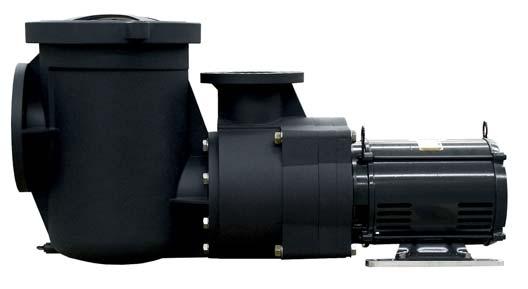
7 EQ Series High Performance Commercial Pump Overview 1 Section 1 Introduction The EQ Series pumps deliver extraordinary performance in every key aspect. They're built to last, of course, and are also built to be incredibly efficient, quiet, lightweight and corrosion-resistant. All of this adds up to a pump that is highly cost effective and suited for a wide range of commercial water applications. At the heart of the EQ's extraordinary performance is its unique impeller design. It provides two significant benefits. First, it means more efficient performance the EQ pump moves more water more quickly than comparable pumps. And secondly, it means the pump's motor doesn't have to work as hard and, as a result, runs cooler and lasts considerably longer. What's more, the Pentair EQ pump has been through a rigorous design, development and testing program so you know it's built to handle the toughest commercial applications for years to come. Available in single and three-phase, 50 and 60 Hz models, the EQ sets the new standard for performance in pumps. No one else in the industry has made a plastic injection-molded pump with performance like this for pool and water applications. EQ Series Pump Patent Pending
8 2 General Features EQ Series = Energy Efficient and Quiet Designed in every detail for maximum efficiency The only non-corrosive, all-plastic pump designed exclusively for the commercial pool and water applications market The EQ impeller features an exclusive design that provides true breakthrough performance Lower load due to efficient impeller design means longer motor life Cam and Ramp lid design with clear lid for added convenience in servicing Additional Features: Closed coupled for quiet stable flow operation Lightweight cm (6") suction and cm (4") discharge with strainer pot Closed impeller for longer motor life Heat-resistant seal operates at up to 66 C (150 F) Bolt-on strainer pot Easy one-man installation Self-priming pump NSF-Listed Models available for water feature applications CE - Conforms with all health, safety and environmental protection standards of the Eurpoean Union. Applies to 50 Hz models only. Metric flange kit available separately: A-EQ-160: Metric fange kit, suction side EQ pump, piping 160mm A-EQ-125: Metric fange kit, discharge side EQ pump, piping 125mm A-EQ-160B: Metric fange kit, suction side EQ pump, piping 160mm for version without strainer pot.
9 3 Section 2 Installation The following general information describes how to install the EQ Series pump. Note: Before installing this product, read and follow all warning notices and instructions starting on page ii. Installing the EQ Series Pump Only a qualified service person should install the EQ Series pump. Mechanical Installation and Pressure Testing Mechanical Installation 1. Carefully remove the pump unit and strainer pot assembly, if included, from its shipping package. 2. The pump will perform best when the suction and return head losses (Total Dynamic Head (TDH)) of the pool system have been carefully determined and the correct pump model selected to fit these requirements. A pump should be selected to operate near the center of its Performance Curve with as high an efficiency as possible. It is also important that the Net Positive Suction Head Available (NPSHA) be greater than the Net Positive Suction Head Required (NPSHR) at the design flow rate. 3. If it is not possible to determine accurate suction and discharge head losses (Total Dynamic Head (TDH)), conservative plumbing practices should be strictly adhered to. This would include installing the pump as close to the pool as possible and at approximately the same level as the pool water level. (See page iv., General Installation Information, regarding when a strainer pot assembly is required.) Use large diameter pipe especially on the suction line to keep flow velocities at or below 1.8 meters per second (mps), (6 feet per second (fps)). Flow velocities in the return plumbing should not exceed 3 mps (10 fps). Also keep elbows and tees to a minimum. Installations where the pump is going to be installed more that 3 meters (10 feet) below or 1.5 meters (5 feet) above the pool water level must be evaluated by an experienced professional to ensure that the pump will function correctly. 4. A solid flat foundation should be provided to support the pump. The area should be well drained so that the pump motor will not be flooded under any circumstances. Ensure that adequate space and lighting around the pump is provided for routine maintenance activities. NOTE Do not install the pump motor within 1.5 meters (5 feet) of the inside walls of the pool wall unless the pump bears the UL listing mark. UL listed pumps may be installed within 1.5 meters (5 feet) of the inside walls of a swimming pool, spa or hot tub only if a solid copper bonding conductor not smaller than No. 10 SWG (No. 8 AWG) is connected from a bonding lug wire connector on the motor to all metal parts of the swimming pool, spa or hot tub structure and to all electrical equipment, metal conduit, and metal piping within 1.5 meters (5 feet) of the inside walls of the swimming pool, spa or hot tub. 5. It is good practice for most installations to install a valve on both the suction and return line so that the pump can be isolated for routine maintenance. However, a valve, elbow or tee installed in the suction line should be no closer to the front of the pump than 5 times the suction line pipe diameter. (i.e cm (6 ) pipe requires a 7.6 meters (30 ) straight run in front of the suction inlet of the pump.)
10 4 Mechanical Installation, cont. d. 6. Assemble the strainer pot assembly, if included, to the pump. Be sure to install the O-Ring (included with the strainer pot assembly) over the protruding plastic ring on the front of the pump housing before mounting the strainer pot. Properly position the strainer pot to the housing and secure in place using the 8 large flange bolts and washers included with the strainer pot assembly. These bolts should not be over tightened as this could damage the pump. Proper technique is to lightly snug each bolt with a wrench. A squealing sound during tightening of the bolts indicates that the bolts are being excessively tightened. 7. Place the pump in its final location and ensure that the mating flanges of the suction and discharge piping are in line and parallel to the flanges on the pump. Resolve any problems with misalignment before bolting the flanges to the pump. 8. The pump may be secured to bolts buried in the concrete by using the holes on the outside of the motor supports. Figure 1. P/N * P/N * P/N * HEX NUT M20 x 25 (5/8-11) (5/8" ID X 1-5/16") MIN OD FLAT WASHER * INCLUDED WITH STRAINER POT Figure 2. SUCTION CONNECTION WITHOUT 6" ANSI CLASS 150 FLANGE STRAINER POT 70 DURO NITRILE OR EPDM 3.2 mm (1/8") THICK GASKET 22.1 mm (5/8" ID X 1-5/16") MIN OD FLAT WASHER A-EQ-160 (6" ANSI CLASS 150) FLANGE SUCTION CONNECTION WITH STRAINER POT 70 DURO NITRILE OR EPDM 3.2 mm (1/8") THICK GASKET HEX HEAD CAP SCREW M20 x 25, 80 mm (5/8-11 X 3-1/4") LG 22.1 mm (5/8") ID X 44 mm (1-5/16") MIN OD FLAT WASHER HEX HEAD CAP SCREW 5/8-11 X 2-1/4" LG 9. Ensure that the flange gasket is properly positioned between the suction flange of the pump and the flange of the suction piping. Use only high quality rubber, full diameter flange gaskets with holes for the bolts to pass through. It may be necessary to hold the gasket in place with either silicone or two or three drops of a cyanoacrylate (super glue) material. Do not use any other grease or glue as they may contain chemicals that could attack the plastic material. Install the flange bolts hand tight on the suction side of the pump. CAUTION On installations where the pump is installed without a strainer pot, use only 15.2 cm (6 ) Schedule 40 PVC pipe when making the final flange connection. Do NOT use Schedule 80 Pipe, as this can cause interference with the pump housing. CAUTION Use large diameter flat washers between the hex nut and the pump flanges to properly distribute the clamping forces on the flange. Tighten the flanges to 27.1 newton/ meters (20 ft.-lb.) unless otherwise specified by the flange manufacturer. If it is not possible to use a torque wrench then care should be taken not to over tighten the flange bolts. Failure to follow the above instructions can result in damaging the pump flange. 10. Properly insert the flange gasket on the discharge port of the pump. Install the flange bolts hand tight on the discharge flange connection. 11. Inspect both the suction and flange connection to ensure alignment remains acceptable. Take any corrective action before tightening the flange bolts to the required torque. CAUTION Suction and discharge piping must be supported by an appropriate system of supports or hangers. Inadequately supported pipe can cause excessive loads to be transmitted to the pump resulting in a structural failure of the pump that could result in flooding and property damage.
11 5 Pressure Testing Certain local codes require that the circulation system be pressure tested with a proof pressure before being commissioned into service or before allowing construction to progress to the next stage. WARNING Improperly pressure testing a circulation system can involve significant risk of property damage or severe personal injury or death. Circulation systems store energy when pressure tested due to the elastic nature of the materials used in construction and due to the compressibility of air that may be contained in the system. The instructions below should be considered a guide only. Each installation should be considered a unique situation that should be carefully investigated for risk. WARNING Never test this equipment with air pressure even if specified by the local code. Even low levels of air pressure result in tremendous storage of energy that can instantaneously be released if a system failure occurs. This instantaneous release of energy can cause failed components to be accelerated to high velocities and to travel distances of meters (100 feet) or more. These components could cause severe personal injury or death if they were to strike a person. 1. Understand the local code. The intent of the code may be to ensure that the piping system with its many bonded joints is leak free. Piping systems typically have a higher pressure capability than the other system components such as the pump or filter. Do not pressure test the pump unless the code specifically requires this. 2. Verify that each component in the system is designed to meet the local code test pressure. Most components should be marked with a maximum operating pressure. If a component is not marked consult the Owner s Instructions that came with the component or consult the manufacturer. 3. Verify that the pressure test will be conducted within the operating temperature listed on the components that make up the circulation system. If no maximum operating temperature is listed then it may be necessary to review the owner s manual or contact the manufacturer for this information. It is common practice for plastic components to be pressure rated at 22 C (72 F). and then derated for temperatures greater than this. 4. Use only a high quality pressure gage that is certified to be accurate for the pressure for which the test is going to be conducted. Do not rely on the pressure gage included with the filtration system as it may not be sufficiently accurate to conduct a pressure test for the system. Please note that the pressure in the system will vary depending on where the pressure is taken due to the weight of the water. 5. Ensure that all air will be evacuated from the system when the water pressure is applied to the system. This will require that all air bleeders on any equipment are open. It also may be necessary to remove some lids or covers on system equipment such as the pump strainer lid to prevent air from being trapped in the system. In addition, there may be other areas of the circulation system where air may be trapped. Do not connect water pressure to the system until you are certain that air will be totally evacuated. 6. Determine the appropriate location in the system to apply the test water pressure. Consider the place in the system that will best ensure that all air will be displaced when water is introduced.
12 6 Pressure Testing, cont d. WARNING Never exceed the maximum operating pressure or temperature limits of the system components. Pumps installed with the EQ Strainer Pot Assembly should not be tested at a pressure that exceeds the value written on the EQ Strainer Pot. See the Owner's Manual that accompanies that product for more instructions. Ensure that pressures higher than those required in the pressure test cannot inadvertently be applied to the circulation system. This may require the use of a pressure regulator between the water supply and the circulation system. Changes in temperature or barometric pressure can cause the internal test pressure to increase or decrease over time once the system is isolated. A pressure relief device should be installed that would prevent the pressure from exceeding the intended test pressure. Exceeding these limits could result in a component failing under pressure. This instantaneous release of energy can cause failed components to be accelerated to high velocities and to travel distances of meters (100 feet) or more. These components could cause severe personal injury or death if they were to strike a person. 7. Slowly apply the water pressure and allow the water to flow out all of the openings intended for air to escape. Close the openings beginning at the lowest level first and progressing to the highest level. Do not close any opening until you are sure that air is completely out of that part of the system. 8. Allow the pressure to slowly build once all of the air openings are closed. Close the valve between the water supply and circulation system to isolate the system from the supply pressure. 9. Monitor the system pressure for a few minutes to ensure that it is stabilized. WARNING Due to the potential risk that can be involved it is recommended that the pressure test be kept to the minimum time required by the local code. Do not allow people to work around the system when the circulation system is under pressure test. Post appropriate warning signs and establish a barrier around the pressurized equipment. If the equipment is located in an equipment room, lock the door and post a warning sign. Never attempt to adjust any closures or lids or attempt to remove or tighten bolts when the system is pressurized. These actions can result in a separation or failure of system components. This instantaneous release of energy can cause components to be accelerated to high velocities and to travel distances of meters (100 feet) or more. These components could cause severe personal injury or death if they were to strike a person. 10. It is normal for the test pressure to drift down slightly during the first few minutes as the circulation system expands under pressure. 11. If the system pressure continues to fall, then bleed off the remaining water pressure in the circulation system and inspect the system for leaks. Look for water on the floor and feel around joints for moisture. 12. Ensure the system is not under pressure before attempting any system adjustments or repairs. 13. Repeat the pressurization sequence once the system leaks have been corrected.
13 This section describes how to secure and wire the EQ pump. Electrical Requirements and Field Wiring Section 3 Electrical Requirements NOTE Do not install the pump motor within 1.5 meters (5 feet) of the inside walls of the pool wall unless the pump bears the UL listing mark. UL listed pumps may be installed within 1.5 meters (5 feet) of the inside walls of a swimming pool, spa or hot tub only if a solid copper bonding conductor not smaller than No. 10 SWG (No. 8 AWG) is connected from a bonding lug wire connector on the motor to all metal parts of the swimming pool, spa or hot tub structure and to all electrical equipment, metal conduit, and metal piping within 5 feet of the inside walls of the swimming pool, spa or hot tub. 7 CAUTION To prevent possible voltage reduction that cause flicker sensations in lighting equipment, this product should be powered by a dedicated power line capable of providing at least 32 A per phase. Other eqipment connected to the same power line may experience operations problems caused by the inrush current during startup of this product. CAUTION This pump is for use with permanently installed pools and may also be used with hot tubs and spas if so marked. Do not use with storable pools. A permanently installed pool is constructed in or on the ground or in a building such that it cannot be readily disassembled for storage. A storable pool is constructed so that it may be readily disassembled for storage and reassembled to its original integrity. WARNING Risk of electrical shock or electrocution. This pool pump must be installed by a licensed or certified electrician or a qualified pool serviceman in accordance with the National Electrical Code and all applicable local codes and ordinances. Improper installation will create an electrical hazard which could result in death or serious injury to pool users, installers, or others due to electrical shock, and may also cause damage to property. Always disconnect power to the pool pump at the circuit breaker before servicing the pump. Failure to do so could result in death or serious injury to serviceman, pool users or others due to electric shock. 1. Ensure that the electrical service is disconnected, properly tagged and locked out before working on the pump. 2. Carefully review the motor label. Take note of the important nameplate information such as volts, amps, phase, HP and code. Most pump models may be field connected so that they can operate on two different voltage circuits. Use extreme care in reviewing the motor wiring diagrams and always verify the voltage of the electrical supply circuit. 3. Carefully review the electrical supply circuit to ensure that it is adequate to meet the pump requirements identified on the motor nameplate. An electrical code letter is identified on the motor nameplate that identifies the load characteristics of the motor.
14 8 Electrical Requirements and Field Wiring, cont d. CAUTION Some single-phase pumps may contain an internal thermal protector designed to temporarily stop the pump if the motor exceeds a preset temperature. The pump will automatically restart when the motor temperature falls to a preset limit. Always disconnect power before working on the pump to eliminate the possibility that the pump could start unexpectedly. Three-phase pumps do not contain an internal thermal protector and must be externally protected by an appropriately sized protective device commonly referred to as a starter. Improper sizing of the starter can result in the motor being destroyed or in frequent tripping of the starter. 4. It is important that all portions of the electrical circuit including the conductors that connect the electrical panel to the pump motor are properly sized based on the nameplate information on the pump. 5. Following the National Electrical Code and any local electrical codes connect the grounding conductor and electrical supply conductors to the motor. Ensure that the pump is properly grounded per the above codes utilizing the grounding screw identified in the terminal box of the pump motor. 6. It will be necessary to confirm that the rotation of the motor is in the correct direction on all three-phase pump units and on certain single-phase pump units. Check wiring diagram to determine if motor can be field wired to rotate in both directions. Checking rotation by energizing the pump for one second and then watching the rotation through the back of the motor as it coasts to a stop. Ensure that the rotation matches the direction arrow on the pump. Operating a pump with the incorrect rotation can cause many problems including poor priming, diminished water flow, excessive noise, overloading of the motor and premature failure of the pump. NOTICE: Due to wide variation in electrical equipment, power equipment, power supply, and installation requirements, this manual does not make specific recommendations concerning auxiliary equipment or fusing /wiring. Wire sizing, wire type, branch circuit fuse protection, motor starter, control equipment, and related items must meet National Electrical Code and local code requirements. Motors are supplied by several manufacturers and nameplate data (service factor, maximum amperage, etc.) will vary. Consult control manufacturer and motor nameplate on your pump to correctly choose and size motor starter and control equipment for your particular installation. Specific electrical questions or problems should be addressed to the manufacturer of the electrical component in question. Voltage/Phase Voltage at motor must be not more than 10% above or below motor nameplate rated voltage or motor may overheat, causing overload tripping and reduced component life. If voltage is less than 90% or more than 110% of rated voltage when motor is running at full load, consult power company. Do not try to connect 3-phase motors to single phase power supply or single phase motors to 3-phase power supply. Emergency Shutoff Install an Emergency Shutoff Switch near pool. Clearly mark this switch and mount it in a location that is accessible to bathers or pool operating personnel (e.g. lifeguards). Make sure that all lifeguards and pool personnel understand the switch s use in case of emergency (entrapment, electrical malfunction, etc.). CAUTION Always fill the pump with water before energizing the pump motor. Operating the pump without water can damage the pump seal within a few seconds.
15 This section describes how to prime the EQ pump. Section 4 Initial Operation of Pump 9 WARNING Do not operate the pump until you have read and understand clearly all the operating instructions and warning messages for all equipment that is a part of the pool circulating system. The following instructions are intended as a guide for initially operating the pump in a general pool installation, however each installation may have unique conditions where the starting procedure could be different. Failure to follow all operating instructions and warning messages can result in property damage or severe personal injury or death. 1. Relieve any pressure that may be trapped in the circulation system. 2. Open all air relief devices on any equipment in the system. 3. Open the appropriate valves on the suction and discharge plumbing. If the pump is installed below the water level of the pool, water will flow into the pump. If the pump is installed above the water level it will be necessary to fill the strainer pot with water up to the suction pipe connection. WARNING The strainer pot may be at a pressure that is higher or lower than the atmospheric pressure. Always open the drain plug on the strainer pot and allow for the pressure to equalize before removing the locking ring. Attempting to remove the locking ring before the pressure is equalized may result in a rapid exchange of pressure. This instantaneous release of energy can cause components to be accelerated to high velocities and to travel distances of 30.5 meters (100 feet) or more. These components could cause severe personal injury or death if they were to strike a person. 4. Stand clear of all equipment and energize the pump. 5. The pump will experience a temporary unstable condition as water and air flow through the pump. During this unstable condition the pump may be noisy and produce erratic flow. If the pump is below or at water level this temporary unstable condition should last only a few seconds. 6. If the pump is installed above the pool water level then the pump must remove the air from the suction piping. This phase of pump operation is referred to as priming. Pumps that are labeled self-priming have demonstrated in a test laboratory that they can prime when installed 3 meters (10 feet) above the pool water level in a time not exceeding 45 minutes. (Exception: Models EQW300 1PH and EQW300 3 PH may require up to 1 hour and 15 minutes to prime to 3 meters (10 feet). Disconnect power to the pump if it does not prime within the time indicated. A pump that will not prime usually indicates a system problem such as an air leak on the suction side of the pump.) WARNING DO NOT open the strainer pot if pump fails to prime or if pump has been operating without water in the strainer pot. Pumps operated in these circumstances may experience a build up of vapor pressure and may contain scalding hot water. Opening the pump may cause serious personal injury. In order to avoid personal injury make sure the strainer pot temperature has cooled to room temperature. Carefully remove the drain plug on the strainer pot and allow the pressure to equalize before removing the locking ring. 7. It is important that once the pump has primed and is operating in a stable manner that the voltage be measured at the pump when first put into service. If the electrical supply circuit is inadequate a voltage drop may occur when the pump is operating under load. The pump will operate most efficiently when operated at the nameplate voltage. Operating the pump at more than 10% above or below the voltage listed on the nameplate could result in the pump not operating properly and may damage the pump motor.
16 10
17 11 Section 5 Maintenance Cleaning of the Strainer Basket 1. The pump is designed to be maintenance free with the exception of requiring a periodic cleaning of the strainer basket. 2. A routine inspection should be done by visually looking through strainer lid for debris while the pump is in operation. The strainer basket should be cleaned when approximately 25 % blocked. Allowing the strainer basket to become excessively blocked will diminish water flow, reduce pump efficiency, cause cavitation and may damage the basket or other pump components. 3. Disconnect power to the pump before cleaning the basket. 4. Close isolation valves on the suction and discharge lines if necessary to prevent flooding. WARNING The strainer pot may be at a pressure that is higher or lower than the atmospheric pressure. Always open the drain plug on the strainer pot and allow for the pressure to equalize before removing the locking ring. Attempting to remove the locking ring before the pressure is equalized may result in a rapid exchange of pressure. This instantaneous release of energy can cause components to be accelerated to high velocities and to travel distances of or 30.5 meters (100 feet) or more. These components could cause severe personal injury or death if they were to strike a person. WARNING If the pump has been energized for a period greater than 45 minutes without water flowing through the pump for any reason, the water in the strainer pot may be hot. Attempting to remove the locking ring without removing the drain plug in the pot and allowing the pressure to equalize may result in the hot water rapidly escaping and causing severe personal injury. 5. Open the drain plug in the strainer pot and allow the pressure to completely stabilize. 6. Remove the locking ring and the clear lid from the strainer pot. 7. Remove the basket and dispose of the debris. Use a water hose and soft brush to remove debris blocking the openings in the basket if required. 8. Replace the basket making sure it is properly oriented. 9. Replace the lid, by aligning the four tabs with the tabs on the strainer pot and making sure the O-ring is clean and is properly located in the groove of the lid. 10. Secure the lid in place by tightening the locking ring hand tight only. Do not over tighten the locking ring as that will make removal difficult. WARNING It is recommended that only water and a soft cloth be used to clean the lid and other pump components. Cleaners may contain chemicals that could damage or weaken pump components causing them to fail and allowing an instantaneous release of energy. This instantaneous release of energy can cause components to be accelerated to high velocities and to travel distances of 30.5 meters (100 feet) or more. These components could cause severe personal injury or death if they were to strike a person.
18 12 Preventative Maintenance It may be possible to extend the life of the pump and to prevent a pump down situation by implementing a preventative maintenance program. This may be done by periodically performing a list of activities and recording certain information to be able to spot potential problems before they become serious. It is recommended that these activities be performed after the filter cleaning procedure so that the information will be taken from the same baseline each time. All or part of the following activities could provide the foundation for a preventative maintenance program. 1. Record the time it takes for the pump to prime and come to a stable operating condition. Increased priming times can indicate a problem. See Section 7, Troubleshooting. 2. Observe the sound coming from the pump housing. A substantial change in sound from inside the pump is a clue that something in the circulation system has changed. 3. Observe the sound coming from the motor. Motor bearings rarely fail without first becoming noisy. 4. Observe the temperature of the motor. The motor is designed to carry the pump load without building up excessive heat. An increase in normal operating temperatures may indicate a potential problem. A thermocouple placed at the motor ventilation discharge opening may be used to monitor motor temperature. It normally takes about 1 hour for the motor temperature to stabilize. See Section 7, Troubleshooting. 5. Record any flow and pressure readings on the circulation system meters and gages. See Section 7, Troubleshooting. 6. Record supply voltage and amps. Supply voltage can change throughout the day depending on other electrical loads in the area. Changes in supply voltage will affect the amp draw and water output of the pump. 7. Inspect the floor around the pump to ensure there are no indications of leaks. Address leaks immediately. A mechanical seal leak is indicated by water dripping between the motor and the motor adaptor. A mechanical seal leak can result in a failed motor bearing. 8. Inspect the exterior pump components for any sign of a structural failure. Most structural failures will start with a hairline crack that originates from a corner where two different shapes intersect. 9. Verify that the support brackets or hangars for the suction and discharge piping are continuing to fully support the weight of the piping.
19 13 Section 6 Servicing WARNING Risk of electrical shock or electrocution. This pool pump must be installed by a licensed or certified electrician or a qualified pool serviceman in accordance with the National Electrical Code and all applicable local codes and ordinances. Improper installation will create an electrical hazard which could result in death or serious injury to pool users, installers, or others due to electrical shock, and may also cause damage to property. Always disconnect power to the pool pump at the circuit breaker before servicing the pump. Ensure that the disconnected circuit is locked out or properly tagged so that it cannot be switched on while you are working on the pump. Failure to do so could result in death or serious injury to serviceman, pool users or others due to electric shock. Read all servicing instructions before working on the pump. The pump is designed to allow for quick servicing of any moving parts without disturbing the plumbing connections. The pump can be serviced with the common tools that are in nearly every service persons toolbox. The following sequential instructions are for a complete disassembly in order to replace a failed motor. The same instructions may be used to perform a partial disassembly to replace any internal component, but following all steps will not be required. CAUTION It is recommended that you replace the motor with the Pentair replacement motor as identified in Section 8. This motor has been thoroughly tested to ensure that it will function appropriately with the pump under a wide variety of operating conditions. If you choose to use another replacement motor it is important that the frame type, the HP, the service factor, the voltage, the phase and the motor speed match exactly to that listed on the original motor. Slight differences in these parameters can cause the motor to not fit the pump correctly or cause the motor to fail prematurely.
20 14 Disassembly 1. Ensure the electric supply circuit is disconnected and is properly tagged and locked out. 2. Disconnect the line supply conductors and the ground conductor from the motor (1) if the motor is being replaced. 3. Close any valves required to prevent flooding when the pump is disassembled. 4. Review the parts breakdown in Section 8, to understand how the pump components are assembled together. 5. Remove the pump housing (22) drain plug (24) and allow the pump to completely drain. 6. Remove the four 5/8 in. hex nuts (23) that secure the motor end assembly to the front housing (22). 7. If the motor support (2) is bolted to a permanent surface it will be necessary to remove the screws (6) that are securing the motor to the motor support (2) to allow for removal of the motor end assembly. 8. Grasp the motor end assembly and pull backwards. It may be necessary to wiggle the motor assembly from side to side to break free the O-Ring seals inside the pump. 9. Pull the motor end assembly free of the housing (22) so that there is adequate access to the internal components. If desired, the supply conductors can be disconnected and the motor end assembly can be taken to a workbench for easier service. 10. Remove the four screws (20) with washers (18) (19) that secure the diffuser (17) to the seal plate (13). 11. Hold the impeller (15) nose and remove the screw (16) and washers (4) (5) that secure the impeller (15). 12. The impeller (15) is also secured to the shaft by a parallel key 1. The impeller (15) can be freed from the shaft and key by grasping the outside of the impeller (15) and pulling the impeller (15) away from the motor (1). It is good practice to inspect the impeller (15) to ensure that the vane passageways are open and that no vanes have been substantially broken or worn. 13. Removing the impeller (15) will expose the two pieces of the mechanical seal (14). It will not be necessary to further disassemble the pump if only a seal replacement is required. 14. The seal plate (13) is attached to the motor adaptor (7) by two dowel pins (26). The seal plate (13) can be freed from these dowel pins (26) by grasping the outside of the seal plate (13) and pulling way from the motor wiggling it from side to side if required. 15. Remove the four screws (10) with washers (8) (9) that secure the motor adaptor (7) to the motor (1). These components could cause severe personal injury or death if they were to strike a person.
21 Assembly 1. Ensure that the two 6 ½ in. long screws (11) with washers (12) are properly inserted into the bottom of the motor adaptor (7) before attaching the motor adaptor (7) to the new motor (1). 2. Properly orient the motor adaptor (7) to the motor (1) and secure in place using the four screws (10) and washers (8) (9). 3. Insert the two dowel pins (26) into the motor adaptor (7). 4. Install the stationary ring of the mechanical seal (14) into the seal plate bore. Ensure that it is fully inserted into the bore with the white surface facing you. CAUTION The mechanical seal is a highly engineered component that must be carefully handled. The contact faces are manufactured to extremely precise tolerances. These faces must be free of all surface dust and debris. Always wash your hands before handling the mechanical seal. Avoid touching the contact faces except for when pressing the seal ring into the bore. Lubricate the rubber portion with a slight amount of soapy water if required to insert it into the bore. Do not use silicone or other lubricants as this can contaminate the seal face. Rinse the seal face if required after assembly to free it of any dirt or debris. 5. Properly orient the seal plate (13), slip it onto the two dowel pins (26) and secure to the motor adaptor (7) by tapping it toward the motor adaptor (7) until there is no clearance between the two parts. 6. Slip the spring portion of the mechanical seal (14) over the motor shaft, being certain that the hard black contact surface is facing the white surface of the stationary seal ring. Use a small amount of soapy water if required to lubricate the rubber of the mechanical seal (14) so that it slips easily over the shaft. 7. Install the shaft key 1 into the shaft of the motor and then install the impeller (15) over the shaft. It will be necessary to align the keyway in the impeller (15) with the key 1. Push the impeller (15) as far as possible onto the motor shaft (1). 8. Install the socket head screw (16) with washers (4) (5) to secure the impeller (15). It is important that the screw (16) be tightened securely and that the impeller (15) is fully seated. 9. Apply a light film of silicone grease to the inside diameter of the brass bushing inside the diffuser (17). This film will assist in properly centering the diffuser bushing to the impeller (15) and will reduce the friction should the parts contact during motor start-up. DO NOT USE ANY OTHER TYPES OF LUBRICANTS. 10. Install the diffuser (17) over the impeller (15) and secure with the four screws (20), but only hand tight. The diffuser (17) has clearance around the four screws (20) that will allow adjustment of the fit of the diffuser (17) around the impeller (15) nose. Rotate the impeller (15) by hand to ensure that it is free to turn and slowly tighten each of the four screws (20). Verify that the impeller (15) is free to turn once the diffuser screws (20) are fully tightened. 11. Lubricate the diffuser O-Ring (21) and the larger seal plate O-Ring (28) with silicone lubricant or Murphy Oil Soap. This will allow the O-Rings to slip into place without getting pinched. Ensure that the big seal plate O-Ring (28) is properly seated on the large diameter of the seal plate (13). 12. Carefully slip the motor end assembly into the housing (22) pushing it forward as far as possible until the large seal plate O-Ring (28) comes into contact with the housing (22). Insert the four 6½ in. long screws (11) through the housing (22) and secure the assembly in place using the washers (12) and nuts (23). Gradually tighten each of the four screws a few turns in a crossing pattern to ensure that the motor assembly is properly centered to the housing. Do not over tighten these screws. CAUTION Failure to follow the above assembly procedures could cause the impeller to bind once the pump is fully assembled. It is possible to remove the strainer basket, reach through the strainer pot and spin the impeller to verify that it will rotate freely. A bound impeller may cause the motor to not start or cause the motor to draw excessive amps. 13. Secure the motor (1) to the motor supports (2). 14. Reconnect the ground and supply conductors. 15. Read and follow the instructions under Section 4, Initial Operation of Pump before putting the pump back into service. 15
22 16 Section 7 Troubleshooting Use the following troubleshooting information to resolve possible problems with your EQ Series pump. WARNING RISK OF ELECTRICAL SHOCK OR ELECTROCUTION. Improperly installation will create an electrical hazard which could result in death or serious injury to pool users, installers, or others due to electrical shock, and may also cause damage to property. 1. If you are not familiar with your pool filtering system and/or heater: a. Do NOT attempt to adjust or service without consulting your dealer, or a qualified pool technician. b. Read the entire Installation & User s Guide before attempting to use, service or adjust the pool filtering system or heater. Note: Turn off power to unit prior to attempting service or repair. Problems and Corrective Actions Problem Corrective Action Pump Will Not Prime Low Flow- High Filter Pressure Low Flow- Low Filter Pressure Motor Does Not Turn Motor Over Heating High Pitch OR Growling Noise coming from WET END of Pump No water in Strainer Pot Lid is not tight Damaged lid O-Ring Water level below Skimmer Strainer or Skimmer Basket clogged Closed Valve in Piping System Air leak in Suction Line Pump installed more than 3 m (10 ft.) above Water Level or otherwise too high for Hydraulic Conditions of Pool Plumbing System Pump Shaft rotating in wrong direction Filter is dirty Restriction in Filter Line Strainer or Skimmer Basket clogged Clogged Impeller Air leak in Suction Line Restriction in Suction Line Cavitation - NPSHA less than NPSHR Pump Shaft rotating in wrong direction Power Switch is off Circuit Breaker has tripped Thermal Protector has tripped Pump is in OFF mode of Timer Motor Shaft is locked by bad Bearing Impeller is jammed Electrical Supply Connections are incorrect Wiring to Pump is undersized Inadequate Voltage supplied to Site Ventilation is inadequate for Motor Voltage differential between legs of 3 Phase Circuit >5% Pump Shaft rotating in wrong direction Air Leak in Suction Line Cavitation - NPSHA less than NPSHR A Valve, Elbow or Tee is located too close to the Suction Inlet of the Pump Pump Shaft rotating in wrong direction
SuperFlo High Performance Pump
 SuperFlo High Performance Pump Installation and User's Guide IMPORTANT SAFETY INSTRUCTIONS READ AND FOLLOW ALL INSTRUCTIONS SAVE THESE INSTRUCTIONS Customer Service If you have questions about ordering
IMPORTANT SAFETY INSTRUCTIONS READ AND FOLLOW ALL INSTRUCTIONS SAVE THESE INSTRUCTIONS. Table of Contents WARNING.
 Eagle Pump Owners Manual IMPORTANT SAFETY INSTRUCTIONS READ AND FOLLOW ALL INSTRUCTIONS SAVE THESE INSTRUCTIONS Table of Contents SECTION I. INSTALLATION... 2 SECTION II. OPERATION & MAINTENANCE... 2 SECTION
TIDALWAVE I/G POOL PUMP INSTRUCTION MANUAL
 TIDALWAVE I/G POOL PUMP INSTRUCTION MANUAL READ THIS MANUAL CAREFULLY BEFORE USING YOUR PUMP 88 PUMP PARTS BREAKDOWN REF # Order # Mfr # Description 1 NEP4 AC 348 Lid Knobs NEP AC 380 Strainer Lid 3 NEP6
2 SPEED PUMP INSTRUCTION MANUAL READ THIS MANUAL CAREFULLY BEFORE USING YOUR 2 SPEED PUMP
 2 SPEED PUMP INSTRUCTION MANUAL READ THIS MANUAL CAREFULLY BEFORE USING YOUR 2 SPEED PUMP 8308 PUMP PARTS BREAKDOWN Ref # Part # Manf. # Descrip on 1 NEP2134 AC 81361 PUMP LID 2 NEP2135 AC 81396 PUMP LID
MAXI PUMP INSTRUCTION MANUAL NE6151B /NE6171B READ THIS MANUAL CAREFULLY BEFORE USING YOUR MAXI PUMP
 MAXI PUMP INSTRUCTION MANUAL NE6151B /NE6171B READ THIS MANUAL CAREFULLY BEFORE USING YOUR MAXI PUMP 8104 MAXI-PUMP PARTS BREAKDOWN Re f # 1 2 3 4 5 6 7a 7b 8 9 10 11 12 13 14 15 16 2 Part # NEP2134 NEP2135
SPARUS 160 ENERGY EFFICIENT AQUACULTURE DUTY PUMP
 AQUATIC ECO-SYSTEMS SPARUS 160 ENERGY EFFICIENT AQUACULTURE DUTY PUMP INSTALLATION AND USER S GUIDE IMPORTANT SAFETY INSTRUCTIONS READ AND FOLLOW ALL INSTRUCTIONS SAVE THESE INSTRUCTIONS i CUSTOMER SERVICE
CHAMPION PUMP OWNER S MANUAL
 CHAMPION PUMP OWNER S MANUAL IMPORTANT SAFETY INSTRUCTIONS READ AND FOLLOW ALL INSTRUCTIONS SAVE THESE INSTRUCTIONS WARNING: Before installing this product, read and follow all warning notices and instructions
SMF PUMP OWNER S MANUAL
 SMF PUMP OWNER S MANUAL IMPORTANT SAFETY INSTRUCTIONS READ AND FOLLOW ALL INSTRUCTIONS SAVE THESE INSTRUCTIONS WARNING: Before installing this product, read and follow all warning notices and instructions
ECONO FLO 2.7HP VARIABLE SPEED PUMP OWNER S MANUAL
 ECONO FLO 2.7HP VARIABLE SPEED PUMP OWNER S MANUAL IMPORTANT SAFETY INSTRUCTIONS READ AND FOLLOW ALL INSTRUCTIONS SAVE THESE INSTRUCTIONS WARNING: Before installing this product, read and follow all warning
LC Series - Light Commercial Pump Station Installation and Operation Manual
 LC Series - Light Commercial Pump Station Installation and Operation Manual Please keep this manual with the pump station Content Rain Bird LC Series Overview... Safety Instruction... Operation... 3 Pump
ECONO FLO VSA 165 VARIABLE SPEED PUMP OWNER S MANUAL
 ECONO FLO VSA 165 VARIABLE SPEED PUMP OWNER S MANUAL IMPORTANT SAFETY INSTRUCTIONS READ AND FOLLOW ALL INSTRUCTIONS SAVE THESE INSTRUCTIONS WARNING: Before installing this product, read and follow all
SERIES 'HE' PLASTIC HORIZONTAL PUMP MODEL: H2 x1½
 SERIES 'HE' PLASTIC HORIZONTAL PUMP MODEL: H2 x1½ OPERATION AND SERVICE GUIDE O-820_R FEBRUARY 2013 Refer to Bulletin P-201 and Parts Lists: P-7200, P-7250. SAFETY PRECAUTIONS BEFORE STARTING PUMP 1. Read
INSTALLATION & OPERATING INSTRUCTIONS
 INSTALLATION & OPERATING INSTRUCTIONS WARNING RISK OF ELECTRIC SHOCK. CONNECT ONLY TO A CIRCUIT PROTECTED BY A GROUND-FAULT CIRCUIT-INTERRUPTER. THE UNIT SHOULD BE INSTALLED BY A QUALIFIED SERVICE REPRESENTATIVE.
OWNERS GUIDE TO INSTALLATION AND OPERATION
 OWNERS GUIDE TO INSTALLATION AND OPERATION SPM SERIES HIGH POWER CENTRIFUGALS READ THESE INSTRUCTIONS CAREFULLY Read these installation instructions in detail before installing your pump. Be sure to check
INSTALLATION INSTRUCTIONS
 INSTALLATION INSTRUCTIONS VARIABLE SPEED BOOSTER PUMP IMPORTANT SAFETY INSTRUCTIONS READ AND FOLLOW ALL INSTRUCTIONS SAVE THESE INSTRUCTIONS IMPORTANT SAFETY INFORMATION WARNING: RISK OF ELECTRICAL SHOCK
Clean & Clear. Cartridge Filter System Owner s Manual IMPORTANT SAFETY INSTRUCTIONS READ AND FOLLOW ALL INSTRUCTIONS SAVE THESE INSTRUCTIONS
 Clean & Clear Cartridge Filter System Owner s Manual IMPORTANT SAFETY INSTRUCTIONS READ AND FOLLOW ALL INSTRUCTIONS SAVE THESE INSTRUCTIONS SECTION I. SECTION II. SECTION III. SECTION IV. SECTION V. SECTION
INTELLILEVEL AUTOMATIC WATER LEVELING SYSTEM FOR POOL AND SPA
 INTELLILEVEL AUTOMATIC WATER LEVELING SYSTEM FOR POOL AND SPA INSTALLATION AND USER S GUIDE IMPORTANT SAFET Y INSTRUCTIONS READ AND FOLLOW ALL INSTRUCTIONS SAVE THESE INSTRUCTIONS 2 CUSTOMER SERVICE /
Elite Primer Baldor Series External Pond Pump
 Elite Primer Baldor Series External Pond Pump ( 5250PPB21, 6440PPB23, 7550PPB26, 9600PPB28) Installation and User s Guide IMPORTANT SAFETY INSTRUCTIONS, READ AND FOLLOW ALL INSTRUCTIONS. SAVE THESE INSTRUCTIONS
HIGH PERFORMANCE 3-PHASE PUMPS
 WHISPERFLOXF AND MAX-E-PROXF HIGH PERFORMANCE 3-PHASE PUMPS INSTALLATION AND USER S GUIDE IMPORTANT SAFETY INSTRUCTIONS READ AND FOLLOW ALL INSTRUCTIONS SAVE THESE INSTRUCTIONS i CUSTOMER SERVICE / TECHNICAL
QUICK PRIME INSTALLATION AND SERVICE MANUAL
 QUICK PRIME INSTALLATION AND SERVICE MANUAL NOTE! To the installer: Please make sure you provide this manual to the owner of the equip ment or to the responsible party who maintains the system. Part #
AQUA-FLO A SERIES. The Bronze Pump designed exclusively for any swimming pool or spa application.
 The Bronze Pump designed exclusively for any swimming pool or spa application. The A Series pump, including motor bracket, impeller, volute and trap, are unit cast from corrosion-resistant fine old world
568X, 587X, 588X Series
 Please read and save this Repair Parts Manual. Read this manual and the General Operating Instructions carefully before attempting to assemble, install, operate or maintain the product described. Protect
Pool Power Pak. III with On/Off Switch UL Models (1 HP), (1-1/2 HP) NEC Models (1 HP), (1-1/2 HP)
, (1-1/2 HP) NEC Models (1 HP), (1-1/2 HP)") the original portable pool Pool Power Pak III with On/Off Switch UL Models 0-1076-000 (1 HP), 0-1077-000 (1-1/2 HP) NEC Models 0-1076-006 (1 HP), 0-1077-006 (1-1/2 HP) Owner's Guide 365-1783 PREPARATION
the original portable pool Pool Power Pak III with On/Off Switch UL Models 0-1076-000 (1 HP), 0-1077-000 (1-1/2 HP) NEC Models 0-1076-006 (1 HP), 0-1077-006 (1-1/2 HP) Owner's Guide 365-1783 PREPARATION
Installation, Operating, and Service Manual. Badu. EcoM3. Swimming Pool Pump
 Installation, Operating, and Service Manual Badu EcoM3 Swimming Pool Pump Technical Support Address: Speck Pumps 8125 Bayberry Road Jacksonville, FL. 32256 USA Hours: 8:00 am to 5:00 pm EST Toll Free:
INSTALLATION, OPERATION, AND MAINTENANCE MANUAL
 INSTALLATION, OPERATION, AND MAINTENANCE MANUAL TUBE AXIAL FANS BTA, WTA, HTA, DDA The purpose of this manual is to aid in the proper installation and operation of the fans. These instructions are intended
CONTENTS CONSIDERATIONS. General Plumbing Component Connection ILLUSTRATION. Control System CONFIGURATION. Voltage Verification CONNECTION
 AIR SERIES SYSTEM INSTALLATION MANUAL CONTENTS CONSIDERATIONS General Plumbing Component Connection 2 2 2 ILLUSTRATION Control System 3 CONFIGURATION Voltage Verification 4 CONNECTION Component Connection
"S" SERIES IMMERSIBLE PUMP OWNER'S MANUAL INSTALLATION OPERATION PARTS Models S12 S16
 Webster Pumps "S" SERIES IMMERSIBLE PUMP OWNER'S MANUAL INSTALLATION OPERATION PARTS Models S12 S16 PLEASE READ THE FOLLOWING INFORMATION PRIOR TO INSTALLING AND USING Webster PUMPS or HAYWARD VALVES,
QUICK PRIME INSTALLATION AND SERVICE MANUAL
 QUICK PRIME INSTALLATION AND SERVICE MANUAL NOTE! To the installer: Please make sure you provide this manual to the owner of the equip ment or to the responsible party who maintains the system. Part #
CHALLENGER CENTRIFUGAL PUMP
 CHALLENGER CENTRIFUGAL PUMP INSTALLATION AND USER S GUIDE IMPORTANT SAFETY INSTRUCTIONS READ AND FOLLOW ALL INSTRUCTIONS SAVE THESE INSTRUCTIONS i CUSTOMER SERVICE / TECHNICAL SUPPORT If you have questions
"S" SERIES IMMERSIBLE PUMP OWNER'S MANUAL INSTALLATION OPERATION PARTS Models S2 S4 S5 SS6 SS7 S8
 Webster Pumps "S" SERIES IMMERSIBLE PUMP OWNER'S MANUAL INSTALLATION OPERATION PARTS Models S2 S4 S5 SS6 SS7 S8 PLEASE READ THE FOLLOWING INFORMATION PRIOR TO INSTALLING AND USING Webster PUMPS or HAYWARD
QUIETFLO OWNER S MANUAL
 QUIETFLO OWNER S MANUAL INSTALLATION, OPERATION & PARTS To prevent potential injury and to avoid unnecessary service calls, read this manual carefully and completley. CAUTION - We highly recommend a qualified
rev3 INSTALLATION & OPERATION MANUAL OIL CIRCULATING HEATING SYSTEM MODEL OSM
 216279-000 rev3 INSTALLATION & OPERATION MANUAL OIL CIRCULATING HEATING SYSTEM MODEL OSM IDENTIFYING YOUR SYSTEM IOM216279-000 The HOTSTART heating system is designed to heat fluids for use in marine
HIGH PERFORMANCE PUMPS
 WHISPERFLOXF AND MAX-E-PROXF HIGH PERFORMANCE PUMPS INSTALLATION AND USER S GUIDE IMPORTANT SAFETY INSTRUCTIONS READ AND FOLLOW ALL INSTRUCTIONS SAVE THESE INSTRUCTIONS P/N 352036 REV. D 8/28/12 i CUSTOMER
Pump - Owner s Manual
 Pump - Owner s Manual INSTALLATION, OPERATION, & PARTS To prevent potential injury and to avoid unnecessary service calls, read this manual carefully and completely. SAVE THIS INSTRUCTION MANUAL Use only
Patterson/AMT Inline Circulator Pump Refer to pump manual for General Operating and Safety Instructions.
 Please read and save this Repair Parts Manual. Read this manual and the General Operating Instructions carefully before attempting to assemble, install, operate or maintain the product described. Protect
OWNER S MANUAL INSTALLATION, OPERATION, & PARTS. Super Pump Series
 P/N: ISSPSERIES REV. A OWNER S MANUAL INSTALLATION, OPERATION, & PARTS *50HZ Models are not UL or CSA Listed. Super Pump Series The Hayward Super Pump TM is specifically engineered for the demanding requirements
569, 570, 571, 572 Series
 Please read and save this Repair Parts Manual. Read this manual and the General Operating Instructions carefully before attempting to assemble, install, operate or maintain the product described. Protect
569, 570, 571, 572 Series
 Please read and save this Repair Parts Manual. Read this manual and the General Operating Instructions carefully before attempting to assemble, install, operate or maintain the product described. Protect
HIGH PERFORMANCE PUMP
 WHISPERFLOXF HIGH PERFORMANCE PUMP INSTALLATION AND USER S GUIDE IMPORTANT SAFETY INSTRUCTIONS READ AND FOLLOW ALL INSTRUCTIONS SAVE THESE INSTRUCTIONS P/N L300203 B1012 i CUSTOMER SERVICE / TECHNICAL
50 HZ. MAX-E-PRO CENTRIFUGAL PUMPS WITH INTEGRAL TRAP
 50 HZ. MAX-E-PRO CENTRIFUGAL PUMPS WITH INTEGRAL TRAP O W N E R S M A N U A L INSTALLATION, OPERATION & PARTS 5P6R Series MODELS HP 1 Phase 3 Phase 3/4 5P6R6D-209 5P6R6D3-209 1 5P6R6E-210 5P6R6E3-210 1-1/2
Panel Fan Series Operators Manual (Galvanized and Polymer)
") Panel Fan Series Operators Manual (Galvanized and Polymer) Galvanized Panel Fan with Three Wing Blade IMPORTANT: READ AND SAVE THESE INSTRUCTIONS Read all instructions carefully before attempting to assemble,
Panel Fan Series Operators Manual (Galvanized and Polymer) Galvanized Panel Fan with Three Wing Blade IMPORTANT: READ AND SAVE THESE INSTRUCTIONS Read all instructions carefully before attempting to assemble,
Patterson/AMT Inline Circulator Pump Refer to pump manual for General Operating and Safety Instructions.
 Please read and save this Repair Parts Manual. Read this manual and the General Operating Instructions carefully before attempting to assemble, install, operate or maintain the product described. Protect
HALLMARK INDUSTRIES INC. HALLMARK INDUSTRIES INC. Safety WARNING WARNING. Must reset the voltage! Shallow Well Jet Pumps
 Safety Important Safety Instructions SAVE THESE INSTRUCTIONS - This manual contains important instructions that should be followed during installation, operation, and maintenance of the product. Save this
Patterson/AMT Inline Circulator Pump Refer to pump manual for General Operating and Safety Instructions.
 Please read and save this Repair Parts Manual. Read this manual and the General Operating Instructions carefully before attempting to assemble, install, operate or maintain the product described. Protect
KREEPY KRAULY PROWLER 910 ROBOTIC ABOVEGROUND POOL CLEANER
 KREEPY KRAULY PROWLER 910 ROBOTIC ABOVEGROUND POOL CLEANER INSTALLATION AND USER S GUIDE IMPORTANT SAFETY INSTRUCTIONS READ AND FOLLOW ALL INSTRUCTIONS SAVE THESE INSTRUCTIONS CUSTOMER SERVICE / TECHNICAL
SELF-PRIMING CENTRIFUGAL PUMPS BMLS-M & BMLS-H
 SELF-PRIMING CENTRIFUGAL PUMPS BMLS-M & BMLS-H INSTALLATION, OPERATION & MAINTENANCE INSTRUCTIONS HP Phase Medium Head High Head 3 1 BMLS 300 M BMLS 300 H 3 3 BMLS 300 M3 BMLS 300 H3 5 1 BMLS 500 M BMLS
Installation Instructions. For the 18 Built-In Dishwasher and Front Color Panels
 Installation Instructions For the 18 Built-In Dishwasher and Front Color Panels Printed in USA 154232102 Before You Begin DO NOT INSTALL DISHWASHER UNTIL YOU HAVE READ ALL INSTRUCTIONS. FOR YOUR SAFETY,
Ultraviolet Systems UV-C 50 INSTALLATION INSTRUCTIONS & PRODUCT MANUAL
 Ultraviolet Systems Inc. UV-C 50 INSTALLATION INSTRUCTIONS & PRODUCT MANUAL TABLE OF CONTENTS SECTION 1 General Information 1A. Description...1 1B. Specifications...1 SECTION 2 Installation 2A. Pool Preparation...
INSTRUCTION AND REPAIR MANUAL
 SECTION 6 ITEM 390 DATED JANUARY 2003 SUPERSEDES SECTION 6 ITEM 390 DATED OCTOBER 2000 INSTRUCTION AND REPAIR MANUAL SERIES 390 6 The 390 Series is a superior commercial Multi-Stage Vertical In-Line Centrifugal
DRAINMAKER INSTALLATION INSTRUCTIONS PREINSTALLATION CHECKLIST
 Manufacturers of... Quality Products since 1866 95 N. Oak St. Kendallville, IN 46755 1-800-345-9422 DRAINMAKER INSTALLATION INSTRUCTIONS PREINSTALLATION CHECKLIST FW0771 0116 Supersedes 0415 MODEL: DATE
INSTALLATION INSTRUCTIONS GEO PRIME TANK. (Patent Pending) GPC
 GPC") INSTALLATION INSTRUCTIONS GEO PRIME TANK (Patent Pending) GPC Table of Contents General Description 2 Installation 3 Flushing and Purging 5 Initial Start up 7 Adding or Checking Fluid 8 Replacing a Pump
INSTALLATION INSTRUCTIONS GEO PRIME TANK (Patent Pending) GPC Table of Contents General Description 2 Installation 3 Flushing and Purging 5 Initial Start up 7 Adding or Checking Fluid 8 Replacing a Pump
INSTALLATION, OPERATING & MAINTENANCE INSTRUCTIONS FOR 350 SERIES CIRCULATION HEATERS
 INDEECO Circulation Heaters are designed to provide years of trouble free operation if properly installed and maintained. Please read and follow these instructions for installing and maintaining the heater.
OWNER S MANUAL INSTALLATION AND OPERATING INSTRUCTIONS REPAIR PARTS LIST
 OWNER S MANUAL INSTALLATION AND OPERATING INSTRUCTIONS REPAIR PARTS LIST SCX1740 SERIES CENTRIFUGAL PUMP High Head - Noryl Impellers MODELS Model ODP MOTORS TEFC MOTORS HP Number 115/230/60/1 20-230/460/60/3
The Danger signal indicates an immediately hazardous situation which, if not avoided, will result in death or serious injury.
 The Danger signal indicates an immediately hazardous situation which, if not avoided, will result in death or serious injury. The Warning signal alerts you to potential hazards or unsafe practices which,
VL Series Pump. Owner s Manual. NOTE - To prevent potential injury and to avoid unnecessary service calls, read this manual carefully and completely.
 ISVL1285 Rev B VL Series Pump Owner s Manual NOTE - To prevent potential injury and to avoid unnecessary service calls, read this manual carefully and completely. READ AND FOLLOW ALL INSTRUCTIONS SAVE
Installation Manual PS-225 & PS-275
 Installation Manual PS-225 & PS-275 Table of Contents Pre-Uncrating Checklist... 1 Verifying System Requirements... 2 Verifying System Direction... 2 Verifying the Electrical Requirements... 2 Removal
CONSUMER SERVICES TECHNICAL EDUCATION GROUP PRESENTS
 CONSUMER SERVICES TECHNICAL EDUCATION GROUP PRESENTS L-71 SinkSpa JETTED SINK Model LJD1306L JOB AID Part No. 8178201 FORWARD This Whirlpool Job Aid, SinkSpa Jetted Sink, (Part No. 8178201), provides the
MDX² INSTALLATION MANUAL
 ANTI-ENTRAPMENT DEBRIS DRAIN MDX² INSTALLATION MANUAL CONCRETE POOLS SUBMERGED SUCTION OUTLET FOR MULTIPLE DRAIN USE FOR USE ON FLOOR SEE SPECIAL INSTRUCTIONS FOR CALIFORNIA AND FLORIDA ON PAGES 4 AND
Instruction Manual - Anti-Siphon Ejector Chlorine & Sulfur Dioxide 500 PPD (10 kg/h) Maximum Capacity
 Maximum Capacity") - Anti-Siphon Ejector Chlorine & Sulfur Dioxide 500 PPD (10 kg/h) Maximum Capacity 100 PPD (2 kg/h) Chlorine or Sulfur Dioxide 250 & 500 PPD (5 & 10 kg/h) Chlorine or Sulfur Dioxide Anti-Siphon Ejector
- Anti-Siphon Ejector Chlorine & Sulfur Dioxide 500 PPD (10 kg/h) Maximum Capacity 100 PPD (2 kg/h) Chlorine or Sulfur Dioxide 250 & 500 PPD (5 & 10 kg/h) Chlorine or Sulfur Dioxide Anti-Siphon Ejector
C-IV 60 CEILING FAN READ AND SAVE THESE INSTRUCTIONS. FAN RATING AC 120V. 60Hz
 C-IV 60 CEILING FAN READ AND SAVE THESE INSTRUCTIONS FAN RATING AC 120V. 60Hz Please do not use any electric or battery powered tools in the assembly and installation of this or any Matthews Fan Company
ULTRA LOW TEMPERATURE FREEZER. User Manual
 ULTRA LOW TEMPERATURE FREEZER User Manual Note:Kaltis reserves the right to modify any parts of this manual without prior notice. 1. No part of this manual may be reproduced in any form, or translated
Instructions for installation and use English. More documents on: H B /09
 TM Instructions for installation and use English EN More documents on: www.zodiac-poolcare.com H0538700.B - 2015/09 Read this manual carefully before installing, maintaining or repairing this appliance!
Built-In Dishwasher. Installation Instructions. BEFORE YOU BEGIN Read these instructions completely and carefully. IMPORTANT The dishwasher MUST be
 Installation Instructions Built-In Dishwasher If you have questions, call 800.GE.CARES (800.432.2737) or visit our website at: www.ge.com BEFORE YOU BEGIN Read these instructions completely and carefully.
Intelligent Variable Speed Pump
 IntelliFlo VS+SVRS Intelligent Variable Speed Pump The ONLY way to comply with new federal anti-body entrapment standards and save money There s simply no better way to add a Safety Vacuum Release System
INSTALLATION & OPERATION MANUAL
 216300-000 rev2 INSTALLATION & OPERATION MANUAL OIL CIRCULATING HEATING SYSTEM FOR HAZARDOUS LOCATIONS MODEL OSE OSX (this page intentionally left blank) IDENTIFYING YOUR SYSTEM IOM216300-000 The HOTSTART
Models Series Series
 Models 3180-Series 3181-Series INDUSTRIAL DIAPHRAGM PUMPS Commercial Duty, 3 GPM/1 LPM FEATURES Sealless Easy Installation Run Dry Ability Flow to 3 GPM/1 LPM Self-Priming Low Amp Draw Thermal Overload
1 1/8 Inch Centrifugal Pump Operation and Maintenance Guide
 1 1/8 Inch Centrifugal Pump Operation and Maintenance Guide Installation Location! The pump should be located as close as possible to the liquid source so that the suction line can be as short and direct
Installation Instructions
 GE Consumer & Industrial Appliances Installation Instructions Junction Box Cover Within this user bag, you will find a junction box cover and a #10 hex head screw used to attach the junction box cover
Installation Instructions Part No , Part No Part No
 Torsion-Flex Motor mount for PSC motors and Rigid-Mount for ECM motors Replacement Kit Cancels: New Installation Instructions Part No. 327752-401, Part No. 327753-401 Part No. 327754-401 IIK-310A-45-11
Remote Water Quality System Standard Equipment (supplied by EPI) Remote Water Quality System Optional Equipment (supplied by EPI)
 Remote Water Quality System Optional Equipment (supplied by EPI)") Page 1 of 11 Parts List Remote Water Quality System Standard Equipment (supplied by EPI) 20sq ft Skimmer-Filter Remote Water Quality Plumbing Kit Heater-Controller Keypad Control 220V 3/4HP Circulation
Page 1 of 11 Parts List Remote Water Quality System Standard Equipment (supplied by EPI) 20sq ft Skimmer-Filter Remote Water Quality Plumbing Kit Heater-Controller Keypad Control 220V 3/4HP Circulation
ultra quiet fan USER MANUAL INSTALLATION OPERATION MAINTENANCE
 USER MANUAL ultra quiet fan INSTALLATION OPERATION MAINTENANCE Z0414808 rev A ISSUED 02/2014 READ AND UNDERSTAND THIS MANUAL PRIOR TO OPERATING OR SERVICING THIS PRODUCT. safety and handling Safety Warning
Panel Fan Series Operators Manual (Galvanized and Polymer)
") Panel Fan Series Operators Manual (Galvanized and Polymer) 52" Belt Drive, Galvanized Panel Fan with Three Wing Blade IMPORTANT: READ AND SAVE THESE INSTRUCTIONS Read all instructions carefully before
Panel Fan Series Operators Manual (Galvanized and Polymer) 52" Belt Drive, Galvanized Panel Fan with Three Wing Blade IMPORTANT: READ AND SAVE THESE INSTRUCTIONS Read all instructions carefully before
Installation GUIDE VDWU524SS VDWU524WSSS FDWU524WS FDWU524 VDWU324SS FDWU324
 Installation GUIDE VDWU524SS VDWU524WSSS FDWU524WS FDWU524 VDWU324SS FDWU324 To prevent accidents, which could cause serious injury or death, as well as machine damage read these instructions before installation
STOP. SAFETY INFORMATION Please read and understand this entire manual before attempting to assemble, operate or install the product.
 STOP Power supply required Questions, problems, missing parts? Before returning to your retailer, call our customer service department at 1-800-742-5044, 7:30 a.m. - 5 p.m., EST, Monday - Friday. 115 volts
TABLE OF CONTENTS. NOTE: Read the entire instruction manual before starting the installation. TROUBLESHOOTING... 13
 R 410A Duct Free Split System Air Conditioner and Heat Pump Product Family: DFS4(A/H) System, DFC4(A/H)3 Outdoor, DFF4(A/H)H Indoor NOTE: Read the entire instruction manual before starting the installation.
GARAGE VAC OWNERS MANUAL READ BEFORE OPERATING YOUR SYSTEM
 GARAGE VAC OWNERS MANUAL READ BEFORE OPERATING YOUR SYSTEM IMPORTANT SAFETY INSTRUCTIONS When using an electrical appliance, basic precautions should always be followed, including the following: * Read
Installation Manual PS-200 & PS-201
 Installation Manual PS-200 & PS-201 Table of Contents Pre-Uncrating Checklist... 1 Verifying System Requirements... 2 Verifying System Direction... 2 Verifying the Electrical Requirements... 2 Removal
ISOLATED DIRECT DRIVE PLENUM FAN (IDDP)
") Our Expertise, Your Air-Moving Solution ISOLATED DIRECT DRIVE PLENUM FAN (IDDP) PART# 0601710001_rev_A INSTALLATION, OPERATION & MAINTENANCE MANUAL Please read and save these instructions for future reference.
Our Expertise, Your Air-Moving Solution ISOLATED DIRECT DRIVE PLENUM FAN (IDDP) PART# 0601710001_rev_A INSTALLATION, OPERATION & MAINTENANCE MANUAL Please read and save these instructions for future reference.
Installation Instructions
 Installation Instructions Built-In Dishwasher If you have questions, call 800-GECARES or visit our website at: www.geappliances.com BEFORE YOU BEGIN Read these instructions completely and carefully. IMPORTANT
USER MANUAL UN-200V / UN-200VH
 USER MANUAL UN-200V / UN-200VH CONTACT US PHONE/FAX Toll Free: 800.465.1004 Phone: 801.486.1004 Fax: 801.486.1007 ADDRESS LACO Technologies, Inc. 3085 West Directors Row Salt Lake City, UT 84104 WEB www.lacotech.com
SECTION STEAM CONDENSATE PUMPS
 PART 1 - GENERAL 1.1 DESCRIPTION SECTION 23 22 23 STEAM CONDENSATE PUMPS SPEC WRITER NOTES: 1. Delete between // ---- // if not applicable to project. Also delete any other item or paragraph not applicable
Owners Manual. SM-HP A SM-HP8-10 Meter. Manual D
 DuraCore TM Fan Owners Manual SM-HP8-64-360A SM-HP8-10 Meter Manual 9-1473D 1 4 5 7 8 9 6 MONEL HARDWARE 7 8 9 STAINLESS HARDWARE 00 FAN BLADE FAN HUB 3 Fan Components Marley Order No. Trial Pitch Angle
Models Series Series
 Models 31800-Series 31801-Series INDUSTRIAL DIAPHRAGM PUMPS 4 GPM/15 LPM FEATURES Self-Priming Easy Installation Can run dry without damage Low Amp Draw Flow to 4 GPM/15 LPM Compact Size Thermal Overload
sta-rite Call C and CC Series Installation/Operation/Parts For further operating, installation, or maintenance assistance:
 OWNER S MANUAL Centrifugal Pumps sta-rite C and CC Series 2791 0397 Installation/Operation/Parts For further operating, installation, or maintenance assistance: Call 1-888-782-7483 293 WRIGHT STREET, DELAVAN,
This label warns for risk of electrical shock when failing to observe.
 MANUAL horizontal centrifugal pumps MB series ic drive SB series mechanical seal 1. Introduction 2. Safety precautions 3. Receipt 4. Installation / Operation and Maintenance 4.1 Installation 4.2 Operation
Hoshizaki America, Inc.
 Hoshizaki America, Inc. Modular Crescent Cuber Models KM-900MAH50 KM-900MRH50 A Superior Degree of Reliability INSTRUCTION MANUAL www.hoshizaki.com Issued: 6-25-2008 IMPORTANT Only qualified service technicians
CELDEK Evaporative Cooler Module Installation, Operation, and Maintenance Manual. CELDEK Evaporative Cooler
 CELDEK Evaporative Cooler Module Installation, Operation, and Maintenance Manual CELDEK Evaporative Cooler RECEIVING AND INSPECTION Upon receiving unit, check for any interior and exterior damage, and
WATLOW IND. WATROD Circulation Heater Installation & Maintenance Manual I&M NUMBER: Page: 1 Date: 6/11/2008 Rev: 2.00
 I&M NUMBER: 316-42-5-1 Page: 1 Pre Installation Check to make sure that heater received is the same as that ordered. Watlow heaters are built to comply with UL and CSA dielectric requirements, it may be
! WARNING. McDonnell & Miller Installation & Maintenance Instructions MM-315(C)
") Models 51, 51-S and 53 Boiler Water Feeders Models 51-2, 51-S-2 and 53-2 Feeder Cut-Off Combinations McDonnell & Miller Installation & Maintenance Instructions MM-315(C) OPERATION Maximum Water Supply
Models 51, 51-S and 53 Boiler Water Feeders Models 51-2, 51-S-2 and 53-2 Feeder Cut-Off Combinations McDonnell & Miller Installation & Maintenance Instructions MM-315(C) OPERATION Maximum Water Supply
KREEPY KRAULY PROWLER 920 ROBOTIC INGROUND POOL CLEANER
 KREEPY KRAULY PROWLER 920 ROBOTIC INGROUND POOL CLEANER INSTALLATION AND USER S GUIDE IMPORTANT SAFETY INSTRUCTIONS READ AND FOLLOW ALL INSTRUCTIONS SAVE THESE INSTRUCTIONS i CUSTOMER SERVICE / TECHNICAL
Use & Care Manual. Electric Tankless Water Heaters. With Installation Instructions for the Installer AP15447 (10/10)
") Use & Care Manual With Installation Instructions for the Installer Electric Tankless Water Heaters The purpose of this manual is twofold: one, to provide the installer with the basic directions and recommendations
Use & Care Manual With Installation Instructions for the Installer Electric Tankless Water Heaters The purpose of this manual is twofold: one, to provide the installer with the basic directions and recommendations
INSTANT HOT WATER DISPENSER
 INSTANT HOT WATER DISPENSER Tank Installation Materials required (not provided) 2 mounting bracket screws (and 2 plastic anchors if attaching to drywall) Shut-Off valve and T fitting Components When you
PANEL FAN SERIES OPERATORS MANUAL (Galvanized and Polymer)
") PANEL FAN SERIES OPERATORS MANUAL (Galvanized and Polymer) Galvanized Panel Fan IMPORTANT: READ AND SAVE THESE INSTRUCTIONS Read all instructions carefully before attempting to assemble, install, operate
PANEL FAN SERIES OPERATORS MANUAL (Galvanized and Polymer) Galvanized Panel Fan IMPORTANT: READ AND SAVE THESE INSTRUCTIONS Read all instructions carefully before attempting to assemble, install, operate
INSTALLATION INSTRUCTIONS
 MASTERTEMP & MAX-E-THERM HEATER DIRECT AIR INTAKE DUCT WITH 3-INCH PVC PIPE KIT MASTERTEMP HEATER [KIT P/N 461031) MASTERTEMP 125 HEATER [KIT P/N 474845) MAX-E-THERM HEATER [KIT P/N 475002) INSTALLATION
Installation & Operating Guide
 5-036 HOT WATER TANK Installation & Operating Guide Read all instructions thoroughly. Keep this guide for future reference. Proof of purchase is required for Warranty. Staple receipt or proof of purchase
DRAFT INSTALLATION INSTRUCTIONS. Solid-State Series !! NOTE!! Covers the following models: Refer to INSERT for additional information
 INSTALLATION INSTRUCTIONS Solid-State Series!! NOTE!! Covers the following models: " CS6100 - CS7100 " CS6200 - CS9200 " CS6220 - CS9220 " CS6230 - CS9230 " CS6500 - CS7500 " CS6330 - CS9300 " CS9400 -
Series 1140 and 1141 Temperature Regulators
 Hoffman Specialty Installation & Maintenance Instructions HS-504(E) Series 1140 and 1141 Temperature Regulators! CAUTION FOLLOW ALL INSTALLATION AND OPERATING INSTRUCTIONS. TURN OFF WATER OR STEAM BEFORE
Indicates a hazardous situation which, if not avoided, will result in death or serious injury.
 Installation Instructions If you have any questions, call 800.GE.CARES (800.432.2737) or visit our Website at: GEAppliances.com In Canada, call 1.800.561.3344 or visit www.geappliances.ca This is the safety
Installation Instructions Built-In Dishwasher
 GE Consumer & Industrial Appliances Installation Instructions Built-In Dishwasher If you have questions, call 800.GE.CARES (800.432.2737) or visit our website at: www.ge.com BEFORE YOU BEGIN Read these
Armstrong J Series Float, Thermostatic Steam Traps, Condensate Controllers & Liquid Drainers Installation and Maintenance Manual
 Armstrong J Series, Thermostatic Steam Traps, Condensate Controllers & Liquid Drainers Installation and Maintenance Manual This bulletin should be used by experienced personnel as a guide to the installation