engineering guide FN Fan-Coil Units High-Performance, Horizontal
|
|
|
- Phoebe Wilson
- 5 years ago
- Views:
Transcription

1 engineering guide FN Fan-Coil Units High-Performance, Horizontal
2 Form EG3 (909) TABLE OF CONTENTS High-Performance, Horizontal Fan-Coil Units Features and Benefits...3 Unit Arrangements...4 Construction Features...6 Standard and Optional Features...8 Coils, Physical Data...9 Physical Data...10 Electric Heat...11 Fan Performance Curves, PSC...12 ECM Fan Motor Option...16 Performance Fan Curves, ECM Motors...17 Motor, Fan and Sound Data...19 Dimensional Data...20 Guide Specifications...27 NOTES: Johnson Controls offers Web-Select, the industry s first web-based rating and selection program for complete unit, coil and sound selection. See your representative or visit our website at for more information. Some drawings are not shown in this catalog. All data herein is subject to change without notice. Drawings not for installation purposes. ETL Report Number City of New York Material and Equipment Acceptance (MEA) File Number E. 2 Johnson Controls
3 High-Performance, Horizontal Fan-Coil Units Form EG3 (909) FEATURES AND BENEFITS PERFORMANCE The Johnson Controls FN Series horizontal high performance fan coil units are designed to maximize flexibility of selection and installation. The units are also designed to exceed the stringent quality standards of the institutional market, while remaining cost competitive in the light commercial segment of the market. Johnson Controls horizontal fan coil units set the new standards for quality, flexibility, and competitive pricing. DESIGN FLEXIBILITY The extensive variety of standard options available on the FN Series units are where you find the versatility to fit any HVAC system designer s needs. Options include: mixing box with linkage, rear or bottom ducted return, foil faced or elastomeric closed cell foam insulation, solid or telescoping bottom panels for unit recessing, single wall stainless steel drain pans, and electric heat with single power connection. All electric heat units are listed with ETL as an assembly and carry the cetl label. All units comply with the latest edition of ARI Standard 440 for testing and rating fan coil units, are certified, and display the ARI symbol. Sizes 14 through 20 exceed the maximum airflow rate in ARI 440 and are therefore not certified. High efficiency motors, fan relays, disconnects and fusing mean easier coordination between mechanical and electrical trades. Coil options allow for three, four or six row chilled water or DX coils. One to four row hot water or one and two row standard steam coils may be placed in the preheat or reheat position. CONVENIENT INSTALLATION units are thoroughly inspected and tested prior to shipment, eliminating potential problems at startup. Motor wiring is brought to a junction box on the outside of the unit casing, reducing electrical hook-up time. Plenum units are field reversible for either rear or bottom return without the need for special adapters and tools. All coils and drain pans are field reversible for right or left side connections. All FN Series fan coil units have a side access electrical enclosure, allowing easy access to all electrical components, terminal blocks and wiring. Available factory installed control packages can greatly reduce field labor and setup time. Consisting of control transformer and all needed relays, these packages integrate seamlessly with either factory provided thermostats or field installed thermostats and controllers. Factory furnished valve packages assure proper fit, operation and performance. Valve packages are completely assembled and shipped loose with the units. QUALITY PRODUCT FN Series fan coil units are built from galvanized steel. This metal surpasses the ASTM 125 hour salt spray test for corrosion and rust. Exposed Model FNX cabinetry is powder coated galvannealed steel. Standard insulation is 1/2 inch thick fiberglass, complying with UL 181 and NFPA 90A. Optional foil faced or elastomeric closed cell foam insulation may be specified. All units, with or without electric heat, are cetl listed and labeled. All wiring is in compliance with NEC, assuring safety and quality for the owner. FN Series fan coil units have a removable fan assembly. The entire fan assembly can be removed from the unit and serviced easily on a workbench. All FN Series fan coil units are shipped completely assembled, reducing field installation time and labor. All Johnson Controls 3
4 Form EG3 (909) UNIT ARRANGEMENTS High-Performance, Horizontal Fan-Coil Units FNP BOTTOM RETURN FNP REAR RETURN WITH SOLID ACCESS PANEL FNP REAR RETURN FNP BOTTOM RETURN W/BOTTOM CEILING PANEL FNP BOTTOM RETURN WITH TELESCOPING BOTTOM PANEL FNF FREE RETURN FNP MIXING BOX WITH TOP & REAR RETURN FNP MIXING BOX W/BOTTOM & REAR RETURN 4 Johnson Controls
5 High-Performance, Horizontal Fan-Coil Units Form EG3 (909) UNIT ARRANGEMENTS FNX DOUBLE DEFLECTION SUPPLY GRILLE AND DUCTED REAR RETURN FNX DUCTED SUPPLY AND SINGLE DEFLECTION REAR RETURN GRILLE FNX DOUBLE DEFLECTION SUPPLY GRILLE AND SINGLE DEFLECTION BOTTOM RETURN GRILLE FNX DUCTED SUPPLY AND DUCTED REAR RETURN FNX DOUBLE DEFLECTION SUPPLY GRILLE AND SINGLE DEFLECTION REAR RETURN GRILLE FNX DUCTED SUPPLY AND SINGLE DEFLECTION BOTTOM RETURN GRILLE Johnson Controls 5
 CONSTRUCTION FEATURES High-Performance, Horizontal Fan-Coil Units MODEL FNP FN Series fan coils have many standard and optional features which are unique to the industry (see page 8 for")
 or foil faced or elastomeric closed cell foam insulation (optional) Galvanized steel casing withstanding 125 hour salt spray test per ASTM B-117 1\" minimum")

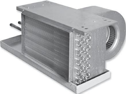
6 Form EG3 (909) CONSTRUCTION FEATURES High-Performance, Horizontal Fan-Coil Units MODEL FNP FN Series fan coils have many standard and optional features which are unique to the industry (see page 8 for a complete listing). Integral filter rack with 1" filter and integral rear ducted (shown) or bottom return on all plenum units. Optional 2" filter available. 1/2" thick fiberglass insulation (standard) or foil faced or elastomeric closed cell foam insulation (optional) Galvanized steel casing withstanding 125 hour salt spray test per ASTM B-117 1" minimum duct collar allows quick field connection of duct work ETL and ARI 440 listed and labeled Chilled water or DX cooling coils up to 6 rows Permanently lubricated, three tap, PSC fan motors designed for quiet and efficient operation Single point power connection on all units with electric heat Removable fan assembly for bottom or rear access and servicing Optional electric resistance heat is ETL listed as an assembly for safety compliance Enclosure allows easy side access to all electrical components Single wall galvanized or stainless steel (optional) drain pans are positively sloped to drain connections Drain pans can be easily removed for cleaning, and reversed for opposite side drain connections Hot water heating coils up to 4 rows, or steam coils up to 2 rows can be mounted in the preheat or reheat position. Maximum of 8 rows total. Optional auxiliary drain connection for added security (not shown) MODEL FNX Horizontal Exposed Cabinet MODEL FNF Horizontal Free Return 6 Johnson Controls
 CONSTRUCTION FEATURES MODELS FNF/FNP/FNX ELECTRICAL ENCLOSURE The side access electrical enclosure provides access to all electric heat and control")


7 High-Performance, Horizontal Fan-Coil Units Form EG3 (909) CONSTRUCTION FEATURES MODELS FNF/FNP/FNX ELECTRICAL ENCLOSURE The side access electrical enclosure provides access to all electric heat and control components. Terminal strips are furnished for simple power and control wiring connections. Multiple knockouts allow wiring entries from either side of the compartment. DRAIN PAN Standard drain pans are externally insulated, single wall galvanized steel with an option for stainless steel. Drain pans are available with secondary drain connection. On concealed models, the FN Series drain pan is easily removable for cleaning or reversing connections. MIXING BOX The optional fully insulated mixing box section comes completely assembled to the FNP unit, featuring low leakage, heavy gauge steel dampers with integral linkage. Damper positioning is field configurable and bottom filter access is standard. A factory provided and installed damper actuator is also available. COILS All fan coils are available in 2 or 4 pipe configurations. The heating coil may be placed in the reheat or preheat position. Heating and cooling coils are field reversible for right or left side connections. FILTERS One inch throwaway filters are tight fitting to prevent air bypass. Filters are easily removable from the bottom without the need for tools. The filter rack is convertible from rear to bottom return without the need for additional parts. Optional 1" and 2" pleated filters are available for use with the FNP unit. POWDER COATED PAINTED SURFACE Exposed cabinet Model FNX features powder coat finish that resists scuffing, scratching, fading, and fingerprints. Johnson Controls 7
8 Form EG3 (909) FEATURES AND OPTIONS High-Performance, Horizontal Fan-Coil Units STANDARD FEATURES Construction All Units ARI 440 certified and labeled Galvanized steel construction 1/2" thick fiberglass insulation 1 1/2" duct discharge collar Four point hanger mounting brackets Plenum units Integral filter rack with 1" throwaway filter Integral rear ducted return - field reversible to bottom return Exposed units Single deflection rear return grille Double deflection discharge grille Durable powder coat paint 18 gauge cabinet construction Coils Cooling - 3, 4 or 6 row chilled water or DX, heat pump compatible Heating - 1, 2, 3 or 4 row hot water or 1 or 2 row steam - reheat or preheat position 8 total rows of cooling and heating coils maximum 1/2" O.D. seamless copper tubes 0.016" tube wall thickness High efficiency aluminum fin surface for optimizing heat transfer, pressure drop and carryover Left or right hand connections field reversible (water coils only) Removable for service Manual air vent Drain Pans Single wall, galvanized steel, externally insulated fire retardant and antimicrobial closed cell foam Positively sloped to drain connection Removable, field reversible 7/8" O.D. primary drain connection Fan Assemblies Forward curved, DWDI centrifugal type 115 volt, single phase, three tap PSC motors Quick disconnect motor connections Removable fan(s)/motor(s) for service Electrical cetl listed for safety compliance Electrical junction box for field wiring terminations Terminal block for field connections Electric Heat cetl listed as an assembly for safety compliance Integral electric heat assembly with removable elements for easy service Automatic reset primary and back-up secondary thermal limits Single point power connection Side-hinged electrical enclosure OPTIONAL FEATURES Construction All units Foil faced fiberglass insulation Elastomeric closed cell foam insulation Plenum units Bottom return Mixing box with top/rear or rear/bottom dampers - field reversible Damper actuator Spare 1" throwaway filters 1" and 2" pleated filters Exposed units Single deflection bottom return grille Ducted supply Ducted rear return Coils Automatic air vents Stainless steel coil casings 0.025" tube wall (standard on steam) Drain Pans Stainless steel with external insulation 5/8" O.D. secondary drain connection Auxiliary drip pans Fan Assemblies & 277 volt, single phase, three tap PSC motors ECM motors Electrical Side access electrical enclosure Silent solid state fan relays SCR fan speed controller Toggle disconnect switch Condensate overflow switch (drain pan) Main fusing Unit and remote mounted three speed fan switches Fan relay packages Control power transformers Electric Heat Door interlocking disconnect switches Main fusing Silent relay / contactor Piping Packages Factory assembled shipped loose for field installation 1/2", 3/4", and 1", 2 way and 3 way normally closed, two position electric motorized valves Isolation ball valves with memory stop Fixed and adjustable flow control devices Unions and P/T ports Modulating control valves High pressure close-off actuators (1/2" = 50 PSIG; 3/4" = 25 PSIG; 1" = 20 PSIG) Thermostats Remote mounted analog, digital display or programmable 2 and 4 pipe control sequences Automatic and manual changeover Integral three speed fan switches 8 Johnson Controls
9 High-Performance, Horizontal Fan-Coil Units Form EG3 (909) COILS, PHYSICAL DATA COILS Johnson Controls offers hot water, chilled water, direct expansion (DX), and standard steam coils for specific application with all FN Series Fan Coil Units. Strict on-site inspection before, during, and after installation guarantees the highest quality and performance available. STANDARD FEATURES Cooling - 3, 4 or 6 row chilled water or DX Heating - 1, 2, 3 or 4 row hot water, or 1 or 2 row steam 8 total rows of cooling and heating coils maximum 1/2" O.D. seamless copper tubes 0.016" tube wall thickness High efficiency aluminum fin surface for optimizing heattransfer, pressure drop and carryover Left or right hand connections Manual air vents OPTIONAL FEATURES Automatic air vents Stainless steel coil casings 0.025" tube wall thickness (standard on steam coils) DX coils are heat pump compatible Web Select. Johnson Controls offers the industry s first web-based fan coil rating and selection program for complete unit, coil and sound selection. See your representative for more information. NOMINAL COIL CONNECTION SIZES COIL TYPE UNIT SIZE WATER STEAM 1 ROW 2 ROW 3 ROW 4 ROW 6 ROW 1 ROW 2 ROW 06 5/8 [16] 5/8 [16] 7/8 [22] 7/8 [22] 7/8 [22] 5/8 [16] 7/8 [22] 08 5/8 [16] 5/8 [16] 7/8 [22] 7/8 [22] 7/8 [22] 5/8 [16] 7/8 [22] 10 5/8 [16] 5/8 [16] 7/8 [22] 7/8 [22] 7/8 [22] 5/8 [16] 7/8 [22] 12 5/8 [16] 7/8 [22] 7/8 [22] 7/8 [22] 1 1/8 [29] 7/8 [22] 7/8 [22] 14 5/8 [16] 7/8 [22] 7/8 [22] 1 1/8 [29] 1 1/8 [29] 7/8 [22] 1 1/8 [29] 16 5/8 [16] 7/8 [22] 7/8 [22] 1 1/8 [29] 1 1/8 [29] 7/8 [22] 1 1/8 [29] 18 5/8 [16] 7/8 [22] 1 1/8 [29] 1 1/8 [29] 1 1/8 [29] 7/8 [22] 1 1/8 [29] 20 5/8 [16] 7/8 [22] 1 1/8 [29] 1 1/8 [29] 1 1/8 [35] 7/8 [22] 1 1/8 [29] NOTES: 1. All dimensional data is outside diameter (O.D.), measured in inches [millimeters]. 2. See submittal drawings for connection locations. 3. Connection sizes are for standard circuit coils. Consult factory for special applications. 4. Direct Expansion (DX) suction header connection sizes are either 5/8" [16mm] or 7/8" [22mm]. Refer to coil selection. 5. DX coils include a fixed orifice distributor for multi-circuited coils. A DX coil with a single circuit requires no distributor. Thermal expansion valves (TXV's) are field supplied by others. FACE AREA, FREE AREA AND FILTER SIZES UNIT COIL FACE 1" THROWAWAY 1" PLEATED 2" PLEATED NOMINAL FILTER SIZES SIZE AREA FACE AREA GROSS MEDIA AREA GROSS MEDIA AREA [0.15] (1) 16 x 16 [406 x 406] 1.62 [0.15] 4.0 [0.37] 5.4 [] [0.19] (1) 16 x 20 [406 x 508] 2.04 [0.19] 4.8 [0.45] 6.8 [0.63] [0.23] (1) 16 x 25 [406 x 381] 2.57 [0.24] 6.0 [0.56] 8.5 [0.79] [0.28] (2) 16 x 16 [406 x 406] 3.23 [] 8.0 [0.74] 10.4 [0.97] [0.33] (1) 16 x 16 & (1) 16 x 20 (1) [406 x 406] & (1) [406 x 508] 3.65 [0.34] 8.8 [0.82] 12.2 [1.13] [0.38] (2) 16 x 20 [406 x 508] 4.08 [0.38] 9.6 [0.89] 13.4 [1.24] [0.43] (1) 16 x 20 & (1) 16 x 25 (1) [406 x 508] & (1) [406 x 635] 4.61 [0.43] 10.8 [] 14.3 [1.33] [0.46] (2) 16 x 25 [406 x 635] 5.14 [0.48] 12.0 [1.11] 17.0 [1.58] NOTES: 1. Face and free areas are in square feet [square meters]. 2. Filter sizes are in inches [millimeters]. Johnson Controls 9
10 Form EG3 (909) PHYSICAL DATA High-Performance, Horizontal Fan-Coil Units ARI STANDARD RATINGS COIL AIRF COOLING CAPACITY WATER POWER MODEL / ARI 440 CFM QT QS Flow Rate WPD INPUT SIZE CERTIFIED Rows FPI (Dry Flow) (BTUH) (BTUH) GPM ft-wg (WATTS) FNF / FNP FNF / FNP FNF / FNP FNF / FNP FNF / FNP FNF / FNP FNF / FNP FNF / FNP NOTES: 1. Based on 80 F DB and 67 F WB EAT, 45 F EWT, 10 F temperature rise, high fan speed. Motor type is PSC and motor voltage is 115/1/60. Airflow under dry coil conditions. All models tested at 0.05" external static pressure. 2. Airflow rate CFM on sizes 14 through 20 exceed maximum ratings in ARI 440 and are therefore not certified. UNIT TYPE FNF FNP UNIT SIZE NOM. CFM HEATING CAPACITY 1 ROW 2 ROW 3 ROW 4 ROW QS QS QS QS (MBH) GPM WPD (MBH) GPM WPD (MBH) GPM WPD (MBH) GPM NOTES: 1.Based on 70 F DB EAT, 180 F EWT, 40 F temperature drop, high fan speed. 2.FNE performance data varies from FNF and FNP units. WPD TOTAL COIL ROWS NOTE: Unit weight data is in pounds [kilograms]. UNIT WEIGHT DATA UNIT SIZE [31] 73 [33] 77 [35] 114 [52] 119 [54] 124 [56] 128 [58] 132 [60] 87 [40] 95 [43] 101 [46] 141 [64] 150 [68] 157 [71] 164 [75] 170 [77] 119 [54] 132 [60] 144 [65] 189 [86] 204 [93] 217 [99] 229 [104] 246 [112] 137 [62] 146 [66] 158 [72] 202 [92] 219 [99] 228 [103] 240 [109] 250 [113] 1 ROW - DRY 5 [2] 6 [3] 7 [3] 8 [4] 10 [5] 10 [5] 11 [5] 12 [5] 1 ROW - WET 7 [3] 9 [4] 10 [5] 11 [5] 14 [6] 14 [6] 16 [7] 17 [8] 2 ROW - DRY 11 [5] 13 [6] 14 [6] 16 [7] 20 [9] 20 [9] 22 [10] 24 [11] 2 ROW - WET 14 [6] 18 [8] 20 [9] 23 [10] 27 [12] 28 [13] 32 [15] 35 [16] 3 ROW - DRY 16 [7] 19 [9] 21 [10] 24 [11] 30 [13] 30 [14] 33 [15] 36 [16] 3 ROW - WET 21 [10] 27 [12] 30 [14] 34 [15] 41 [19] 42 [19] 48 [22] 52 [24] 4 ROW - DRY 21 [10] 25 [12] 29 [13] 33 [15] 40 [18] 40 [18] 44 [20] 48 [22] 4 ROW - WET 27 [12] 35 [16] 41 [19] 46 [21] 54 [25] 56 [25] 64 [29] 69 [31] 5 ROW - DRY 26 [12] 30 [14] 34 [16] 38 [17] 42 [19] 46 [21] 50 [23] 54 [25] 5 ROW - WET 33 [15] 39 [18] 45 [21] 51 [23] 57 [26] 63 [29] 70 [32] 77 [35] 6 ROW - DRY 32 [15] 38 [17] 43 [19] 49 [22] 59 [27] 61 [28] 67 [30] 71 [32] 6 ROW - WET 42 [19] 53 [24] 61 [28] 69 [31] 80 [36] 85 [39] 97 [44] 103 [47] 7 ROW - DRY 38 [17] 42 [19] 48 [22] 54 [25] 60 [28] 66 [30] 72 [33] 78 [35] 7 ROW - WET 49 [23] 56 [26] 63 [29] 70 [32] 77 [35] 84 [38] 91 [42] 98 [45] 8 ROW - DRY 43 [20] 49 [22] 55 [25] 61 [28] 67 [30] 73 [33] 79 [36] 85 [39] 8 ROW - WET 55 [26] 63 [29] 71 [32] 79 [36] 87 [40] 95 [43] 103 [47] 111 [50] COMPONENT FNF BASE UNIT FNP BASE UNIT FNP WITH MIXING BOX FNX BASE UNIT 10 Johnson Controls
11 High-Performance, Horizontal Fan-Coil Units Form EG3 (909) ELECTRIC HEAT STANDARD FEATURES ETL listed as an assembly for safety compliance Single point power connection Mounted in preheat position Automatic reset primary and back-up secondary thermal limits Internal wiring rated at 105 C Integral electric heat assembly with removable element for easy service OPTIONAL FEATURES Solid state silent relay Door interlocking disconnect switch Main fusing USEFUL FORMULAS kw* = CFM x ΔT x 1.085** Ø AMPs = kw x 1000 Volts * 1kW = 3413 BTU/H ** Capacity at sea level Altitude Considerations: Reduce by for each 1000 ft. of altitude above sea level. Example: 5000 ft./1000 ft. = 5 5 x = = ELECTRICAL CALCULATIONS INFORMATION 1. Refer to MCA/MOP Calculator at for MCA and/or MOP calculations. 2. Non-Fused Door Interlock Disconnect Switch shall be sized according to MCA. 3. Fused Door Interlock Disconnect Switch and Main Fusing shall be sized according to MOP. UNIT SIZE ELECTRIC HEAT SELECTION CHART (AMPS) MBH KW VOLTS AMPS NOTES: 1. Shaded areas indicate kw and voltage options not available. 2. Available voltages are single phase, 60 hertz. 3. Heaters over 48 AMPs are subdivided and fused per NEC. Johnson Controls 11
12 Form EG3 (909) FAN PERFORMANCE CURVES, PSC High-Performance, Horizontal Fan-Coil Units GENERAL FAN NOTES, PSC MOTORS 1. Fan curves depict actual performance of each motor tap without any additional fan balance adjustment. Actual capacities which fall below each curve can be obtained by adding an adjustment device. Units should not be run prior to installation of downstream ductwork; otherwise, damage to the motor may result. 2. Johnson Controls Fan Coil Units are equipped with permanent split-capacitor (PSC) motors with three separate taps (High, Medium and Low) which provide variable horsepower outputs. Most often, size selections are conservative and actual CFM requirements and/or external static pressure requirements are lower than those specified. In this case, the unit fan motor can be run at low or medium tap, substantially reducing the operating cost of the unit. 3. All fan curves are for 115/1/60 motors and include pressure losses for cabinet, electric heater, and 3 or 4 row coil. Plenum units include a clean 1" throwaway filter. For other coil configurations, adjust performance curves based on pressure losses for the coils as selected with the Johnson Controls Coil Selection Program. 4. See page 19 for fan motor electrical data. 5. For additional high static pressure applications and rating points, contact factory. SIZE 06 SIZE 08 FNF HPF Free Return FNF HPF Free Return MED MED HPP FNP Plenum Plenum Return Return FNP Plenum Return HPP Plenum Return MED MED HPE FNX Exposed Cabinet HPE FNX Exposed Cabinet MED MED Johnson Controls
13 High-Performance, Horizontal Fan-Coil Units Form EG3 (909) FAN PERFORMANCE CURVES, PSC SIZE 10 SIZE 12 HPF FNF Free Return FNF HPF Free Free Return Return MED MED HPP FNP Plenum Plenum Return Return HPP FNP Plenum Plenum Return Return MED MED HPE FNX Exposed Exposed Cabinet HPE FNX Exposed Cabinet MED MED Johnson Controls 13
14 Form EG3 (909) FAN PERFORMANCE CURVES, PSC SIZE 14 High-Performance, Horizontal Fan-Coil Units SIZE 16 HPF FNF Free Return HPF FNF Free Return MED MED HPP FNP Plenum Plenum Return Return 1.10 HPP FNP Plenum Plenum Return Return MED MED HPE FNX Exposed Exposed Cabinet Cabinet HPE FNX Exposed Cabinet MED MED Johnson Controls
15 High-Performance, Horizontal Fan-Coil Units Form EG3 (909) FAN PERFORMANCE CURVES, PSC SIZE 18 SIZE 20 FNF HPF Free Free Return Return FNF Free Return HPF Free Return MED MED HPP FNP Plenum Return HPP FNP Plenum Return MED MED HPE FNX Exposed Exposed Cabinet Cabinet HPE FNX Exposed Exposed Cabinet MED MED Johnson Controls 15
 ECM FAN MOTOR OPTION High-Performance, Horizontal Fan-Coil Units THE ENERGY EFFICIENT SOLUTION Johnson Controls offers an alternative to the PSC motor that significantly increases the")
16 Form EG3 (909) ECM FAN MOTOR OPTION High-Performance, Horizontal Fan-Coil Units THE ENERGY EFFICIENT SOLUTION Johnson Controls offers an alternative to the PSC motor that significantly increases the operating efficiency of fan coil units. This motor is frequently referred to as an ECM (electronically commutated motor). It is a brushless DC (BLDC) motor utilizing a permanent magnet rotor. The motor has been in production for years and is commonly used in residential HVAC units. Fan speed control is accomplished through a microprocessor based variable speed controller (inverter) integral to the motor. The motor provides peak efficiency ratings between 70 & 80% for most applications. ECM FEATURES AND BENEFITS Ultra-High Motor & Controller Energy Efficiency DC motors are significantly more efficient than AC motors. Due to the permanent magnet, DC design, the ECM maintains approximately 75% efficiency at all speeds. Pressure Independent Fan Volume The integral microprocessor based controller includes a feature that provides sensorless (no external feedback) constant airflow operation by automatically adjusting the speed and torque in response to system pressure changes. This breakthrough will no doubt have far reaching benefits and endless applications. For starters, the fan volume supplied to the space will not significantly change as a filter becomes loaded. The air balance process will become simpler and more accurate since the fan volume will not need to be re-adjusted after the diffuser balance is accomplished. Factory Calibrated Fan Volume Due to the pressure independent feature, the fan capacity is calibrated at the factory at the nominal airflow rate. Within the published flow rate and external pressure limits, the fan motor will automatically adjust to account for the varying static pressure requirements associated with different unit configurations and downstream duct configurations. This feature should not preclude the final field air balance verification process during the commissioning stage of a project. An electronic (PWM) speed control device is provided to allow field changes of the fan capacity as the need arises. Fan volume can be field calibrated in two fashions. First, a potentiometer is provided allowing manual adjustment using an instrument type screwdriver. In addition, the fan volume can be calibrated through the BMS using an analog output (2 to 10VDC typical) to the speed controller. A fan volume verses DC volts calibration chart is provided. Designer / Owner Flexibility The ECM incorporates ball bearings in lieu of sleeve bearings typically utilized with an induction motor. Unlike a sleeve bearing motor, the ECM does not have a minimum RPM requirement for bearing lubrication. This allows it to operate over a much wider speed range. A reduced spare parts inventory is another plus. Custom Applications Programmable Fan Operation Boundless control opportunities arise due to the controllability of a DC motor combined with an integral microprocessor. Various input signals can direct the motor to behave in an application specific mode. For instance, multiple discrete fan capacities can be achieved. In addition, the fan speed can be varied in response to the space temperature load. The fan is also programmed for a soft start. The motor starts at a low speed and slowly ramps up to the required speed. Extended Motor Life The high motor efficiency provides a significantly reduced operating temperature compared to an induction motor. The lower temperature increases the longevity of all electrical components and therefore the life of the motor. The ball bearings do not require lubrication and do not adversely impact the motor life. Most fan coil applications will provide a PSC motor life between 60,000 and 100,000 hours. Expected ECM motor life will be considerably longer than a PSC motor, due to the reduced operating temperature and ball bearing components. Application Most variable speed electronic devices, including the ECM operate with a rectified and filtered AC power. As a result of the power conditioning, the input current draw is not sinusoidal; rather, the current is drawn in pulses at the peaks of the AC voltage. This pulsating current includes high frequency components called harmonics. Harmonic currents circulate on the delta side of a Delta- Wye distribution transformer. On the Wye side of the transformer, these harmonic currents are additive on the neutral conductor. A transformer used in this type of application must be sized to carry the output KVA that will include the KVA due to circulating currents. Careful design must be provided when connecting single-phase products to three-phase systems to avoid potential problems such as overheating of neutral wiring conductors, connectors, and transformers. In addition, design consideration must be provided to address the degradation of power quality by the creation of wave shape distortion. In summary, proper consideration must be given to the power distribution transformer selection and ground neutral conductor design to accommodate the 3-phase neutral AMPs shown in the adjacent table. Specific guidelines are available from the factory. 16 Johnson Controls
17 High-Performance, Horizontal Fan-Coil Units Form EG3 (909) PERFORMANCE FAN CURVES, ECM MOTORS GENERAL FAN NOTES, ECM MOTORS 1. Fan curves depict actual performance at the maximum speed of the ECM motor. Depending upon external static pressure, flow rates are achievable anywhere within the curve boundary by adjusting the motor speed through the electronic interface control board. 2. Airflow rates will be constant for varying degrees of external static pressure caused by filter loading or other duct system variables once the electronic interface control board is set to desired flow rate. 3. Fan curves compensate for the pressure losses of the unit cabinet, coil rows, and a loaded throwaway filter. For job specific fan curves please run the Web-Select rating and selection program. 4. ECM motors operate using a rectified AC power source that is converted to a non-sinusoidal DC power wave form. Harmonic distortion may occur and circulate on the power distribution system. Circulating harmonic currents are potentially additive on the neutral conductors of 3-phase, 4-wire Wye distribution systems. Neutral conductors must be engineered to account for the additional current (amperes) encountered. 5. See page 19 for ECM motor electrical data. 1.1 HPP FNP Size Size With 1/3 HP ECM Motor 0.9 FNP Size 08 With 1/3 HP ECM Motor HPP Size 08 With 1/3 HP ECM Motor (200 Minimum, 700 Maximum) (300 Minimum, 800 Maximum) 1.0 HPP FNP Size Size With 1/3 HP ECM Motor Motor 1.1 HPP FNP Size With (2) 1/3 HP ECM Motors (300 Minimum, 1000 Maximum) (200 Minimum, 1500 Maximum) Johnson Controls 17
18 Form EG3 (909) PERFORMANCE FAN CURVES, ECM MOTORS High-Performance, Horizontal Fan-Coil Units HPP FNP Size Size With With (2) 1/3 1/3 HP HP ECM ECM Motors Motors HPP FNP Size Size With (2) 1/3 HP ECM Motors (600 Minimum, 1800 Maximum) (600 Minimum, 1900 Maximum) 1.0 HPP FNP Size Size & 20 With (2) (2) 1/3 1/3 HP HP ECM ECM Motor Motors (600 Minimum, 2000 Maximum) ECM AIRF UNIT FACTORY CFM RANGE SIZE SET CFM MIN. MAX Johnson Controls
19 High-Performance, Horizontal Fan-Coil Units Form EG3 (909) MOTOR, FAN AND SOUND DATA MOTOR AND FAN DATA UNIT SIZE FAN SPEED MOTOR HP 120/1/ /1/60 277/1/60 (Quantity) # OF ECM ECM ECM PSC ECM FANS PSC FLA 3-Phase Neutral Current PSC FLA 3-Phase Neutral Current PSC FLA 3-Phase Neutral Current High (1) 1/ Medium (1) 1/8 (1) 1/ Low (1) 1/ High (1) 1/ Medium (1) 1/6 (1) 1/ Low (1) 1/ High (1) 1/ Meduim (1) 1/5 (1) 1/ Low (1) 1/ High (2) 1/ Medium (2) 1/8 (2) 1/ Low (2) 1/ High (2) 1/ Medium (2) 1/6 (2) 1/ Low (2) 1/ High (2) 1/ Medium (2) 1/5 (2) 1/ Low (2) 1/ High (2) 1/ Medium (2) 1/5 (2) 1/ Low (2) 1/ High (2) 1/ Medium (2) 1/5 (2) 1/ Low (2) 1/ NOTES: 1. Motor electrical data is nameplate data. Actual data will vary with application. 2. Motors nameplated for /1/60. Data is at 230 volts. 3. ECM motors operated on 208/1/60 power result in reduced airflow Johnson Controls 19
20 Form EG3 (909) DIMENSIONAL DATA High-Performance, Horizontal Fan-Coil Units FNF FREE RETURN UNITS Drawings are not to scale and are not for installation purposes. 20 Johnson Controls
21 High-Performance, Horizontal Fan-Coil Units Form EG3 (909) DIMENSIONAL DATA FNF FREE RETURN UNITS Drawings are not to scale and are not for installation purposes. Johnson Controls 21
22 Form EG3 (909) DIMENSIONAL DATA High-Performance, Horizontal Fan-Coil Units FNP PLENUM UNITS Drawings are not to scale and are not for installation purposes. 22 Johnson Controls
23 High-Performance, Horizontal Fan-Coil Units Form EG3 (909) DIMENSIONAL DATA FNP PLENUM UNITS Drawings are not to scale and are not for installation purposes. Johnson Controls 23
 DIMENSIONAL DATA High-Performance, Horizontal Fan-Coil Units FNP WITH MIXING BOX")
24 Form EG3 (909) DIMENSIONAL DATA High-Performance, Horizontal Fan-Coil Units FNP WITH MIXING BOX Drawings are not to scale and are not for installation purposes. FN FN 24 Johnson Controls
25 High-Performance, Horizontal Fan-Coil Units Form EG3 (909) DIMENSIONAL DATA FNX EXPOSED CABINET UNITS Drawings are not to scale and are not for installation purposes. Johnson Controls 25
26 Form EG3 (909) DIMENSIONAL DATA High-Performance, Horizontal Fan-Coil Units FN TELESCOPING / FILTER AND SOLID BOTTOM ACCESS PANELS Drawings are not to scale and are not for installation purposes. 26 Johnson Controls
27 High-Performance, Horizontal Fan-Coil Units Form EG3 (909) GUIDE SPECIFICATIONS GENERAL Furnish and install Johnson Controls Model FN Horizontal Concealed Direct Drive Fan Coil Units where indicated on the plans and in the specifications. Units shall be completely factory assembled, tested and shipped as one piece. All units shall be capable of meeting or exceeding the scheduled capacities for cooling, heating and air delivery. All unit dimensions for each model and size shall be considered maximums. Units shall be ETL listed in compliance with UL/ANSI Standard 1995, and be certified as complying with the latest edition of ARI Standard 440. CONSTRUCTION All unit chassis shall be fabricated of heavy gauge galvanized steel panels able to meet 125 hour salt spray test per ASTM B-117. All exterior panels shall be insulated with 1/2" thick fiberglass insulation with a maximum k value of.24 (BTU in) / (hr ft2 F) and rated for a maximum air velocity of 5000 f.p.m. Insulation must meet all requirements of ASTM C1071 (including C665), UL 181 for erosion, and carry a 25/50 rating for flame spread/smoke developed per ASTM E-84, UL 723 and NFPA 90A. Option: Provide foil-faced insulation in lieu of standard. Foil insulation shall meet or exceed the requirements stated above, and in addition meet ASTM Standards C-665 and C for biological growth in insulation. Insulation shall be lined with aluminum foil, fiberglass scrim reinforcement, and 30 pound kraft paper laminated together with a flame resistant adhesive. All exposed edges shall be sealed to prevent any fibers from reaching the air stream. Option: Provide Elastomeric Closed Cell Foam Insulation in lieu of standard. Insulation shall conform to UL 181 for erosion and NFPA 90A for fire, smoke and melting, and comply with a 25/50 Flame Spread and Smoke Developed Index per ASTM E-84 or UL 723. Additionally, insulation shall comply with Antimicrobial Performance Rating of 0, no observed growth, per ASTM G-21. Polyethylene insulation is not acceptable. All concealed units shall have a minimum 1 1/4" duct collar on the discharge. Plenum units shall have a minimum 1" duct collar on the return. Option: For concealed units, provide a hinged bottom access panel either solid or with bottom return single deflection grille. A telescoping plenum section is available with bottom return option. All exposed units shall have exterior panels fabricated of galvannealed steel. Option: For exposed units, the side and bottom access panels shall be attached with quick open fasteners to allow for easy removal and access for service. Option: For exposed units, provide double deflection discharge grille and either a rear return or bottom return single deflection grille, powder coat painted to match unit color. Supply and return duct connections are available. Unit mounting shall be by hanger holes provided at a minimum of four locations. FAN ASSEMBLY Unit fan shall be a dynamically balanced, forwardly curved, DWDI centrifugal type constructed of 18 gauge zinc coated galvanized steel for corrosion resistance. Motors shall be high efficiency, permanently lubricated sleeve bearing, permanent split-capacitor type with UL and CSA listed automatic reset thermal overload protection and three separate horsepower taps. Single speed motors are not acceptable. The fan assembly shall be easily removable for servicing the motor and blower at, or away from the unit. The entire fan assembly shall be able to come out of the unit by removing four nuts per fan and unplugging the motor(s). Plenum unit fan assemblies shall be easily serviced through the filter opening or through the bottom panel. Option: Provide an electronic (SCR) fan speed controller as an aid in balancing the fan capacity. The speed controller shall have a turn down stop to prevent the possibility of harming the motor bearings, and incorporate electrical noise suppression to minimize noise on the incoming power lines. Option: Provide ECM motor in lieu of standard PSC motor. COILS All cooling and heating coils shall optimize rows and fins per inch to meet the specified capacity. Coils shall have seamless copper tubes and shall be mechanically expanded to provide an efficient, permanent bond between the tube and fin. Fins shall have high efficiency aluminum surface optimized for heat transfer, air pressure drop and carryover. All coils shall be hydrostatically tested at 450 PSIG air pressure under water, and rated for a maximum of 300 PSIG working pressure at 200 F. Direct expansion cooling coils shall include a fixed orifice distributor. All evaporator coils shall be factory sealed and charged with a minimum 5 PSIG nitrogen or refrigerated dry air. Steam coils shall be standard steam type suitable for temperatures above 35 F and 15 PSIG maximum working pressure. All coils shall be provided with a manual air vent fitting to allow for coil venting. Option: Provide automatic air vents in lieu of manual air vents. Cooling and heating coils shall be in a common tube sheet. Water coils on concealed models shall be field reversible for right or left hand connections. Heating coils shall be furnished in the reheat or preheat position. Johnson Controls 27
28 GUIDE SPECIFICATIONS DRAIN PANS Primary condensate drain pans shall be single wall; heavy gauge galvanized steel for corrosion resistance, and extend under the entire cooling coil. Drain pans shall be of one-piece construction and be positively sloped for condensate removal. Drain pans shall be field reversible for right or left hand connections. The drain pan shall be externally insulated with a fire retardant, closed cell foam insulation. The insulation shall carry no more than a 25/50 Flame Spread and Smoke Developed Rating per ASTM E-84 and UL 723 and an Antimicrobial Performance Rating of 0, no observed growth, per ASTM G-21. Option: Provide a single wall primary drain pan constructed entirely of heavy gauge stainless steel for superior corrosion resistance. Stainless steel drain pans shall be externally insulated and meet or exceed the requirements stated above. Option: Provide a secondary drain connection on the primary drain pan for condensate overflow. Option: Provide a condensate overflow switch in the primary drain pan for condensate overflow. FILTERS All plenum and exposed units shall be furnished with a minimum 1" nominal glass fiber throwaway filter. Filters shall be tight fitting to prevent air bypass. Plenum and exposed unit filters shall be easily removable from the bottom of the unit without the need for tools. Option: Provide unit with 1" or 2" pleated filters rated at 25-30% efficiency and MERV 6 based on ASHRAE MIXING BOX SECTION Provide a fully insulated integral mixing box section with return and outside air dampers, including the interconnecting damper linkage. Mixing box section shall be shipped attached to the concealed plenum unit as an assembly. Damper actuator to be factory provided, mounted, and wired to control enclosure. ELECTRICAL Units shall be furnished with single point power connection. Provide an electrical junction box with terminal strip for motor and other electrical terminations. The factory mounted terminal wiring strip consists of a multiple position screw terminal block to facilitate wiring terminations for the electric control valves and thermostats. ELECTRIC HEAT Furnish an electric resistance heating assembly as an integral part of the fan coil unit, with the heating capacity, voltage and kilowatts scheduled. The heater assembly shall be designed and rated for installation on the fan coil unit without the use of duct extensions or transitions, and be located in the unit as to not expose the fan assembly to excessive leaving air temperatures that could affect motor performance. The heater and unit assembly shall be listed for zero clearance and meet all NEC requirements, and be ETL listed with the unit as an assembly in compliance with UL/ANSI Standard All heating elements shall be open coil type Ni-Chrome wire mounted in ceramic insulators and located in an insulated heavy gauge galvanized steel housing. All elements shall terminate in a machine staked stainless steel terminal secured with stainless steel hardware for corrosion resistance. The element support brackets shall be spaced no greater than 3-1/2" on center. All internal wiring shall be rated for 105 C minimum. All heaters shall include over temperature protection consisting of an automatic reset primary thermal limit and back up secondary thermal limit. All heaters shall be single stage unless noted otherwise on the plans. All units with electric heat shall be provided with an incoming line power distribution block, designated to accept single point power wiring capable of carrying 125% of the calculated load current. PIPING PACKAGES Provide a standard factory assembled valve piping package to consist of a 2 or 3 way, on/off, motorized electric control valve and two ball isolation valves. Control valves are piped normally closed to the coil. Maximum entering water temperature on the control valve is 200 F, and maximum close-off pressure is 40 PSIG (1/2"), 20 PSIG (3/4"), or 17 PSIG (1"). Maximum operating pressure shall be 300 PSIG. Option: Provide 3-wire floating point modulating control valve (fail-in-place) in lieu of standard 2-position control valve with factory assembled valve piping package. Option: Provide high pressure close-off actuators for 2-way on/off control valves. Maximum close-off pressure is 50 PSIG (1/2"), 25 PSIG (3/4"), or 20 PSIG (1"). Option: Provide either a fixed or adjustable flow control device for each piping package. Option: Provide unions and/or pressure-temperature ports for each piping package. Piping package shall be completely factory assembled, including interconnecting pipe, and shipped separate from the unit for field installation on the coil, so as to minimize the risk of freight damage. Printed on recycled paper Form: EG3 (909) Supersedes: EG3 (608) 2008 Johnson Controls, Inc. P.O. Box 423, Milwaukee, WI Printed in USA
engineering guide FH Fan-Coil Units Low-Profile, Horizontal
 engineering guide FH Fan-Coil Units Low-Profile, Horizontal FORM 115.26-EG7 (908) Table of contents FH Fan-Coil Units Low-Profile, Horizontal Features and Benefits... Construction Features... Standard
FCC Fan-Coil Units High-Performance, Vertical
 FCC Fan-Coil s High-Performance, Vertical Model FCC construction features Piping and supply-duct connections are from top of unit, eliminating the need for side or back access Right or left-hand configurations
catalog CDV Fan-Coil Units High-Performance, Vertical
 catalog CDV Fan-Coil Units High-Performance, Vertical Catalog: ET115.26-EG8 (415) TABLE OF CONTENTS CDV Fan-Coil Units High-Performance, Vertical Features and Benefits... 3 Construction Features... 4 Standard
Chilled Water DOAS Fan Powered Terminal Units
 Chilled Water DOAS Fan Powered Terminal Units CHILLED WATER DOAS FAN POWERED TERMINAL UNITS DOAS TERMINAL UNITS FEATURES AND BENEFITS MINIMUM VENTILATION CONTROL The DOAS unit provides the Designer, Owner
Horizontal and Vertical DIRECT DRIVE BLOWER COIL UNITS. Rating and selection at
 Horizontal and Vertical DIRECT DRIVE BER COIL UNITS Rating and selection at www.enviro-tec.com CDH/CDV TABLE OF CONTENTS Construction Features...3 Fan Assembly...4 Optional Construction...5 Electric Heat...6
SSL & SBS Engineering Guide
 REDUCED-FOOTPRINT VERTICAL BLOWER COIL UNITS SSL & SBS Engineering Guide SO TOUGH, WE GUARANTEE IT. SSL SBS Table of Contents Features and Benefits... 3 Construction Features... 4 Features and Options...
PRODUCT CATALOG BLOWER COILS.
 2016 PRODUCT CATALOG BLOWER COILS www.superiorrex.com SBH / SBV Series Design Features DESIGNED FOR MAXIMUM FLEXIBILITY Both Horizontal and Vertical Belt Drive Blower Coils are designed to maximize flexibility
SSL / SBS Sales Guide BLOWER-COILS REDUCED-FOOTPRINT, VERTICAL
 SO TOUGH, WE GUARANTEE IT. SSL / SBS Sales Guide BLOWER-COILS REDUCED-FOOTPRINT, VERTICAL SSL SBS www.superiorrex.com SSL / SBS Series: BIG ON FEATURES; SMALL IN SIZE Contractors All SSL/SBS model blower-coil
Submittal. RBVR Vertical Concealed Floor Mount FCU RBVR
 FCU RBVR 1.0 07 25 18 RBVR Vertical Concealed Floor Mount Unit Size 02 03 04 06 08 10 A 23 3/16 [589] 27 3/16 [691] 33 3/16 [843] 43 3/16 [1097] 45 3/16 [1148] 59 3/16 [1503] B 22 ¾ [578] 26 ¾ [679] 32
MHCCW Chilled Water Ceiling Concealed With 5kW Electric Heat 2-Pipe Heat / Cool Fan Coil 30,000 BTUH
 MHCCW-10-05 Chilled Water Ceiling Concealed With 5kW Electric Heat 2-Pipe Heat / Cool Fan Coil 30,000 BTUH Rev. 1.21 HVAC Guide Specifications Chilled Water Fan Coil with Electric Heat 2-Pipe Nominal Size:
MHCCW Chilled Water Ceiling Concealed Without Electric Heat 2-Pipe Heat / Cool Fan Coil 18,000 BTUH
 MHCCW-06-00 Chilled Water Ceiling Concealed Without Electric Heat 2-Pipe Heat / Cool Fan Coil 18,000 BTUH Rev. 1.21 HVAC Guide Specifications Chilled or Hot Water Fan Coil 2-Pipe Nominal Size: 18,000 BTUH
MHNCCW (4-Pipe) Chilled/Hot Water Ceiling Concealed 208/230V 4-Pipe Heating & Cooling Fan Coil 12,000 BTUH
 Chilled/Hot Water Ceiling Concealed 208/230V 4-Pipe Heating & Cooling Fan Coil 12,000 BTUH") MHNCCW-04-01 (4-Pipe) Chilled/Hot Water Ceiling Concealed 208/230V 4-Pipe Heating & Cooling Fan Coil 12,000 BTUH Rev. 1.2 HVAC Guide Specifications Chilled and Hot Water Fan Coil 4-Pipe Nominal Size: 12,000
MHNCCW-04-01 (4-Pipe) Chilled/Hot Water Ceiling Concealed 208/230V 4-Pipe Heating & Cooling Fan Coil 12,000 BTUH Rev. 1.2 HVAC Guide Specifications Chilled and Hot Water Fan Coil 4-Pipe Nominal Size: 12,000
RAV Engineering Guide
 VERTICAL HIGH-RISE FAN COIL UNITS RAV Engineering Guide SO TOUGH, WE GUARANTEE IT. RAVM RAVL RAVE RAVS RARM RARS RARP Table of Contents Features and Benefits... 3 Construction Features... 4 Standard and
FAN TERMINAL UNITS Constant Volume (Series Flow), Standard Design
, Standard Design") FAN TERMINAL UNITS Constant Volume (Series Flow), Standard Design Fan motor (PSC or ECM). UL Listed 1 insulation conforms to UL Test 181 and NFPA 90A. Plenum air filter rack. (Filter Optional) Casing has
FAN TERMINAL UNITS Constant Volume (Series Flow), Standard Design Fan motor (PSC or ECM). UL Listed 1 insulation conforms to UL Test 181 and NFPA 90A. Plenum air filter rack. (Filter Optional) Casing has
Product Specifications. Vertical Floor Consoles By First Co.
 NOW WITH 18 GAUGE CABINET AND FACTORY INSTALLED SERVICE SWITCH Product Specifications VFB Series VSB Series VCB Series Vertical Console Fan Coils 300-00 CFM Vertical Floor Consoles By First Co. VFB Series
SKYPAK II, 3 Ton Series, gives you a
 SKYPAK II 3 ton Heating And Cooling self-contained Package SKYPAK II, 3 Ton Series, gives you a complete air-conditioning and heating system as an all in one package unit. Designed for convenient through-the-wall
CFFWA4P-08-1-U Chilled/Hot Water Universal Mount Fan Coil (4-Pipe) 4-Pipe Heat / Cool Fan Coil 24,000 BTUH
 4-Pipe Heat / Cool Fan Coil 24,000 BTUH") CFFWA4P-08-1-U Chilled/Hot Water Universal Mount Fan Coil (4-Pipe) 4-Pipe Heat / Cool Fan Coil 24,000 BTUH Rev. 1.3 HVAC Guide Specifications Chilled and Hot Water Universal Mount Fan Coil 4-Pipe Nominal
CFFWA4P-08-1-U Chilled/Hot Water Universal Mount Fan Coil (4-Pipe) 4-Pipe Heat / Cool Fan Coil 24,000 BTUH Rev. 1.3 HVAC Guide Specifications Chilled and Hot Water Universal Mount Fan Coil 4-Pipe Nominal
SKYPAK II, 3 Ton Series, gives you a
 SKYPAK II 3 ton Heating And Cooling self-contained Package SKYPAK II, 3 Ton Series, gives you a complete air-conditioning and heating system as an all in one package unit. Designed for convenient through-the-wall
SECTION FAN COIL UNITS
 PART 1 GENERAL 1.1 RELATED DOCUMENTS A. Drawings and general provisions of the Contract, including General and Supplementary Conditions and Specification Sections, apply to this Section. B. Related Sections:
CFFWA4P-16-1-U Chilled/Hot Water Universal Mount Fan Coil (4-Pipe) 4-Pipe Heat / Cool Fan Coil 48,000 BTUH
 4-Pipe Heat / Cool Fan Coil 48,000 BTUH") CFFWA4P-16-1-U Chilled/Hot Water Universal Mount Fan Coil (4-Pipe) 4-Pipe Heat / Cool Fan Coil 48,000 BTUH Rev. 1.3 HVAC Guide Specifications Chilled and Hot Water Universal Mount Fan Coil 4-Pipe Nominal
CFFWA4P-16-1-U Chilled/Hot Water Universal Mount Fan Coil (4-Pipe) 4-Pipe Heat / Cool Fan Coil 48,000 BTUH Rev. 1.3 HVAC Guide Specifications Chilled and Hot Water Universal Mount Fan Coil 4-Pipe Nominal
CFFWA4P-12-1-U Chilled/Hot Water Universal Mount Fan Coil (4-Pipe) 4-Pipe Heat / Cool Fan Coil 36,000 BTUH
 4-Pipe Heat / Cool Fan Coil 36,000 BTUH") CFFWA4P-12-1-U Chilled/Hot Water Universal Mount Fan Coil (4-Pipe) 4-Pipe Heat / Cool Fan Coil 36,000 BTUH Rev. 1.3 HVAC Guide Specifications Chilled and Hot Water Universal Mount Fan Coil 4-Pipe Nominal
CFFWA4P-12-1-U Chilled/Hot Water Universal Mount Fan Coil (4-Pipe) 4-Pipe Heat / Cool Fan Coil 36,000 BTUH Rev. 1.3 HVAC Guide Specifications Chilled and Hot Water Universal Mount Fan Coil 4-Pipe Nominal
Modular Supply Make-Up Air Unit
 Modular Supply Make-Up Air Unit Model MSX Flexible Design Factory Assembled Heating Options Hot Water Steam Electric Cooling Options Evaporative Direct Expansion Chilled Water November 2009 Product Features
Vertical V*B Series Fan Coil Technical Catalog
 Vertical V*B Series Fan Coil Technical Catalog Vertical Hideaway (VCB) 200 CFM to 1200 CFM The Vertical Hideaway (VCB) fan coil unit is designed for concealed applications. The coil section is lined with
HORIZONTAL LOW PROFILE FAN COIL IN ROOM HORIZONTAL LOW PROFILE FAN COIL UNITS IN ROOM
 HORIZONTAL LOW PROFILE FAN OIL IN ROOM HORIZONTAL LOW PROFILE FAN OIL UNITS IN ROOM HORIZONTAL LOW PROFILE FAN OIL IN ROOM Model series 4H Low Profile, Blow-through Design Sloped drain pan Galvanized or
SKYPAK II Heating & Cooling Self Contained Packages
 SKYPAK II Heating & Cooling Self Contained Packages SKYPAK II gives you a complete airconditioning and heating system as an all-in-one package unit. Designed for conventional through-the-wall installation
SeasonMaker ThinLine Fan-coil Units
 Catalog C: 720-12 SeasonMaker ThinLine Fan-coil Units Type TSH & TSC Horizontal Design TSS, TPF, TSF & TSB Vertical Design C L I S T E D Ratings Certified by the Air Conditioning & Refrigeration Institute
Guide Spec Summary. Option List. Date: 05/21/2001. EarthWise VAV Terminal Units Full Spec. Prepared by: Phone Number: Prepared for:
 Date: 05/21/2001 Time: 02:57:44 PM Job Name: EarthWise VAV Terminal Units Full Spec Location: AnyTown, Earth Prepared by: Phone Number: Prepared for: Guide Spec Summary Option List SINGLE & DUAL DUCT UNIT
Complete HVAC Capability. Central Station Air Handling Units. Publication No. WT-CSX-0616A
 Publication No. WT-CSX-0616A Central Station Air Handling Units Complete HVAC Capability Horizontal Draw-Thru to Size 65 Vertical Draw-Thru to Size 50 1000 to 60,000 CFM Forward Curved or Airfoil Wheels
CATALOG. SKYPAK Self-Contained Heating/Cooling Units
 CATALOG SKYPAK Self-Contained Heating/Cooling Units FORM SK145.00-EG6 (1211) TABLE OF CONTENTS SKYPAK Self-Contained Heating/Cooling Units Introduction...3 Product Overview...3 Nomenclature...4 SKYPAK
SeasonMaker ThinLine Fan-coil Units
 Catalog C: 720-12 SeasonMaker ThinLine Fan-coil Units Type TSH & TSC Horizontal Design TSS, TPF, TSF & TSB Vertical Design C L I S T E D Ratings Certified by the Air Conditioning & Refrigeration Institute
MHNCCX DX with Hot Water Heat Ceiling Concealed 4-Pipe Heat / Cool Fan Coil 12,000-36,000 BTUH
 MHNCCX DX with Hot Water Heat Ceiling Concealed 4-Pipe Heat / Cool Fan Coil 12,000-36,000 BTUH 318 MHNCCX NOMENCLATURE BREAKDOWN 4-Pipe Heat/Cool Ceiling Concealed Fan Coil MHNCCW- XX - XX Ceiling Concealed
SECTION AIR HANDLING UNIT
 SECTION 15800 - AIR HANDLING UNIT PART 1 - GENERAL 1.01 RELATED DOCUMENTS A. Basic Requirements: Provisions of Section 15010, BASIC MECHANICAL REQUIREMENTS, and Section 15030, ELECTRICAL REQUIREMENTS FOR
RetroAire Model Number: 9,000 to 36,000 Btuh (2.6 to 10.5 kw)
") Indoor Single Package Vertical, Air-Cooled Heat Pump Unit RetroAire Model Number: Capacity Range: VPRH 9,000 to 36,000 Btuh (2.6 to 10.5 kw) Part 1 General 1.01 UNIT DESCRIPTION A. Indoor, single package
Indoor Single Package Vertical, Air-Cooled Heat Pump Unit RetroAire Model Number: Capacity Range: VPRH 9,000 to 36,000 Btuh (2.6 to 10.5 kw) Part 1 General 1.01 UNIT DESCRIPTION A. Indoor, single package
MH1WC4W-06-1-B Chilled/Hot Water 1-Way Cassette Fan Coil
 MH1WC4W-06-1-B Chilled/Hot Water 1-Way Cassette Fan Coil 4-Pipe Heat / Cool Fan Coil 18,000 BTUH Rev. 1.11 HVAC Guide Specifications Chilled and Hot Water Cassette Fan Coil 4-Pipe Nominal Size: 18,000
Advance Product Data. Features/Benefits. 42WKN Hydronic Fan Coil Units
 Advance Product Data 42WKN Hydronic Fan Coil Units 3 4 to 2 1 2 Tons UNIT SIZES 004-010 UNIT SIZES 016,020 The new Carrier Hydronic Cassette offers a modern solution for a wide variety of small and medium
C13-Series Engineering Guide
 Engineering Guide Effective January 2018 Horizontal Air-Cooled, Water-Cooled, Chilled Water and Heat Pump Contents Product Features............................... 3 Product Options................................
Large Capacity Fan Coil Units Catalog Belt-Drive and Direct-Drive Cabinet and Hideaway Models
 Large Capacity Fan Coil Units Catalog 735-12 Belt-Drive and Direct-Drive Cabinet and Hideaway Models Table of Contents Agency Listing and Nomenclature... 3 Overview....................................
FLD = Furnished by Trane U.S. Inc. / Installed by Equipment Submittal Page 3 of 13
 Tag Data - Split System Air Conditioning Units (Large) (Qty: 6) Item Tag(s) Qty Description Model Number A1 20 ton vfd 6 6-25 Ton Unitary Split Systems ( SSC2 TTA24004H00-TWE240E404A TTA Air Condensing
Brown University Revised August 3, 2012 Facilities Design & Construction Standards SECTION AIR HANDLING UNITS
 SECTION 23 70 00 AIR HANDLING UNITS PART 1. GENERAL 1.1 Section includes air-handling units to 15,000 cfm and accessories. 1.2 Related Sections 1 : A. Division 01 - Brown University Standard for Narragansett
1.1 This section applies to air handling units for HVAC Systems.
 AIR HANDLING UNITS GENERAL INFORMATION 1.1 This section applies to air handling units for HVAC Systems. DESIGN REQUIREMENTS 2.1 Design Criteria a. The decision to use modular central station air handling
SPLIT-SYSTEM EVAPORATOR BLOWERS K2EU060, K4EU090, K3EU120 & K1EU180 5 Thru 15 Nominal Tons DESCRIPTION ACCESSORIES FIELD INSTALLED
 (491) SPLIT-SYSTEM EVAPORATOR BLOWERS K2EU060, K4EU, K3EU & K1EU180 5 Thru 15 Nominal Tons DESCRIPTION These completely assembled units include a well-insulated cabinet, a DX cooling coil with copper tubes
H3/V3 Series Horizontal and Vertical Indoor Air Handling Units. Engineering Catalog
 H3/V3 Series Horizontal and Vertical Indoor Air Handling Units Engineering Catalog Table of Contents AAON H3/V3 Series Features and Options Introduction... 6 H3/V3 Base Model Description... 7 Unit Size...
SECTION PACKAGED ROOFTOP AIR CONDITIONING UNITS
 SECTION 15732 - PACKAGED ROOFTOP AIR CONDITIONING UNITS PART 1 - GENERAL 1.1 SECTION INCLUDES A. Package roof top unit. B. Heat exchanger. C. Refrigeration components. D. Unit operating controls. E. Roof
VertiCool Aurora Engineering Guide
 Engineering Guide Effective August 2016 Air-Cooled, Water-Cooled and Water Source Heat Pump Contents Product Features... 3 Options... 4 Physical Data...5-6 Air-Cooled Performance Data (a) (b) (c)...7-8
VERTICAL FAN COIL UNITS
 VERTICAL FAN COIL UNITS VERTICAL FAN COIL UNITS Model: CT & TCE 2 - Pipe 350 cfm to 1200 cfm capacity 4-row water coil 120v or 24v controls Electric heating coil (TCE Model) Fresh air connection from remote
Electric Coils. Blower Coils. Product Information
 Product Information General Information Electric heat coils are an available accessory for use with Price blower coil units. The electric heating coils have been specific ally designed to suit Price blower
SECTION AIR COILS
 PART 1 - GENERAL 1.1 RELATED DOCUMENTS A. Drawings and general provisions of the Contract, including General and Supplementary Conditions and Specification Sections, apply to this Section. B. Related Sections:
KINGS COUNTY JAIL EXPANSION PHASE III COUNTY OF KINGS SECTION
 SECTION 237433, PART 1 - GENERAL 1.1 RELATED DOCUMENTS A. Drawings and general provisions of the Contract, including General and Supplementary Conditions and Division 01 Specification Sections, apply to
A. Product Data: Include rated capacities, operating characteristics, furnished specialties, and accessories.
 Page 238219-1 SECTION 238219 - PART 1 - GENERAL 1.1 RELATED DOCUMENTS A. Drawings and general provisions of the Contract, including General and Supplementary Conditions and Division 01 Specification Sections,
CB18/CBS18 Bulletin # September 1994 Supersedes August 1986
 ENGINEERING DATA CB18 SERIES UP-FLOW CBS18 SERIES HORIZONTAL 2 To 5 Ton (7 To 18 kw) Nominal Cooling Capacity 7200 To 102 400 Btuh (2.1 To 30.0 kw) Optional Electrical Heat ENGINEERING DATA COILS MATCHED
Concealed Ducted Split Series R-407C MBH
 Concealed Ducted Split Series R-407C 4-60 MBH Ducted Split with Hermetic Compressor Tropical 50 Hz For more technical information please visit Table of Contents INTRODUCTION NOMENCLATURE UNIT RATING SUMMARY
VariCool VAV Engineering Guide
 Engineering Guide Effective September 2017 Water-Cooled and Chilled Water, Variable Air Volume Contents Product Features... 3 UNIT FEATURES... 3 Product Features... 4 Marvel Plus Microprocessor Control
HP SERIES HPP Plenum Return Shown
 HP SERIES FAN COILS INSTALLATION, OPERATION & MAINTENANCE Supersedes ET115.24-NOM1 (511) Form ET115.24-NOM1 (615) HP SERIES HPP Plenum Return Shown INTRODUCTION ENVIRO-TEC fan coils represent a prudent
Indirect Gas-Fired Make-Up Air
 Indirect Gas-Fired Make-Up Air Model IG 800 to 7,000 cfm Up to 400,000 Btu/hr Multiple Furnace Control Options Optional Evaporative Cooling May 20041 Product Features Model IG Indirect Gas-Fired Make-Up
Advance Release September 2009
 Vertical Air Cooled DSV Series R 410A Model DSV096 DSV120 DSV144 DSV180 Nominal Cooling (Tons) 8 10 12 15 Refrigerant R 410A R 410A R 410A R 410A Cooling Performance Gross Cooling Capacity(Btu/h) 95,000*
SINGLE DUCT TERMINAL UNITS
 Performance Data AHRI Certification and Performance Notes Model Series 3000 asic Unit AHRI Certification Rating Points VAV: Fiberglass Inlet Size Airflow cfm l/s Min. Inlet Ps w.g. Pa Discharge Sound Power
MAC-060HE-01-L High Efficiency Air-Cooled Chiller Air-Cooled Chillers for Global Residential and Light Commercial Micro Climates Rev 1.
 MAC-060HE-01-L High Efficiency Air-Cooled Chiller Air-Cooled Chillers for Global Residential and Light Commercial Micro Climates Rev 1.2 HVAC Guide Specifications Air-Cooled Liquid Chiller with Low Ambient
SPLIT-SYSTEM EVAPORATOR BLOWER DESCRIPTION FEATURES L4EU NOMINAL TONS
 036-21096-001 (0101) SPLIT-SYSTEM EVAPORATOR BLOWER L4EU240 20 NOMINAL TONS DESCRIPTION This 20 ton evaporator blower is designed with two distinct modules to provide maximum application flexibility. The
UNIVERSITY OF MISSOURI Central Station Air-Handling Units March
 GENERAL: 1. This section provides criteria for the design and installation of air handling units. DESIGN GUIDELINES: Design General 1. Location 1.1. For new construction, and existing buildings where possible,
MAC-036HE-02-L High Efficiency Air-Cooled Chiller Air-Cooled Chillers for Global Residential and Light Commercial Micro Climates Rev 1.
 MAC-036HE-02-L High Efficiency Air-Cooled Chiller Air-Cooled Chillers for Global Residential and Light Commercial Micro Climates Rev 1.1 HVAC Guide Specifications Air-Cooled Liquid Chiller with Low Ambient
MAC-048HE-01-L High Efficiency Air-Cooled Chiller Air-Cooled Chillers for Global Residential and Light Commercial Micro Climates Rev 1.
 MAC-048HE-01-L High Efficiency Air-Cooled Chiller Air-Cooled Chillers for Global Residential and Light Commercial Micro Climates Rev 1.1 HVAC Guide Specifications Air-Cooled Liquid Chiller with Low Ambient
MAC-120HE-03 Air-Cooled Chiller
 MAC-120HE-03 Air-Cooled Chiller 10 Ton / 120,000 BTUH Air-Cooled Chiller 380/415/460-3-50/60 1 HVAC Guide Specifications Air-Cooled Liquid Chiller Nominal Size: 10 Tons Multiaqua Model Number: MAC-120HE-03
A. Section includes split-system air-conditioning units consisting of separate evaporator-fan and compressor-condenser components.
 Page 238126-1 SECTION 238126 - This Section includes requirements for the LEED Rating System. However, equipment specified in this Section may not qualify for LEED Rating System prerequisites and credits.
SPLIT-SYSTEM HEAT PUMPS 50 AND 60 HZ DESCRIPTION
 SPLIT-SYSTEM HEAT PUMPS 50 AND 60 HZ E3FB090/E1FB120/F3EH090 & 120 7-1/2 & 10 NOMINAL TONS (60 HZ) 7 & 9 NOMINAL TONS (50 HZ) (9.0-9.2 EER) 208/230/460 VOLT ONLY 208/230 VOLT ONLY DESCRIPTION YORK has
SECTION CONVECTION HEATING AND COOLING UNITS
 PART 1 GENERAL 1.01 SECTION INCLUDES A. Baseboard radiation. B. Finned tube radiation. C. Convectors. D. Unit heaters. E. Cabinet unit heaters. F. Fan-coil units. G. Unit ventilators. H. Blower-coil units.
CWA2 Chilled Water Fan Coil With or Without Electric Heat 2-Pipe Heat / Cool Fan Coil 18,000-60,000 BTUH
 CWA2 Chilled Water Fan Coil With or Without Electric Heat 2-Pipe Heat / Cool Fan Coil 18,000-60,000 BTUH 233 CWA2 NOMENCLATURE BREAKDOWN 2-Pipe Heat/Cool with Electric Heat Multiposition Fan Coil Nominal
TECHNICAL GUIDE DESCRIPTION SPLIT-SYSTEM AIR-COOLED CONDENSING UNITS MODELS: HF-07 FEATURES B-0703
 TECHNICAL GUIDE SPLIT-SYSTEM AIR-COOLED CONDENSING UNITS MODELS: HF-07 DESCRIPTION These Sunline 2000 units are completely assembled, piped and wired at the factory to provide one-piece shipment and rigging.
ENGINEERING GUIDE. Water-Cooled Self-Contained Units C-Series, Vertical
 ENGINEERING GUIDE Water-Cooled Self-Contained Units C-Series, Vertical TABLE OF CONTENTS Introduction...2 Product Overview...3 Nomenclature...4 General Data...5 Cooling Performance Data....6 Evaporator
Catalog C: McQuay Horizontal Concealed Fan Coil Unit
 Catalog C: 700-1 McQuay Horizontal Concealed Fan Coil Unit Model THC Sizes 200 Through 1200 CFM McQuay THC Horizontal Concealed Fan Coil Nomenclature F THC 1 H02 Fan-coil Type of Unit THC = Horizontal
TECHNICAL GUIDE SPLIT-SYSTEM AIR-COOLED EVAPORATOR BLOWER 25, 30, 40 & 50 TON LA300, LB360, 480 & 600 (50 Hz) PROVEN PERFORMANCE GENERAL FEATURING
 PROVEN PERFORMANCE GENERAL FEATURING") TECHNICAL GUIDE SPLIT-SYSTEM AIR-COOLED EVAPORATOR BLOWER 25, 30, 40 & 50 TON LA300, LB360, 480 & 600 (50 Hz) PROVEN PERFORMANCE GENERAL The LA/LB line is a flexible performer. LA300, LB360 & 480 can be
TECHNICAL GUIDE SPLIT-SYSTEM AIR-COOLED EVAPORATOR BLOWER 25, 30, 40 & 50 TON LA300, LB360, 480 & 600 (50 Hz) PROVEN PERFORMANCE GENERAL The LA/LB line is a flexible performer. LA300, LB360 & 480 can be
Direct Gas-Fired Make-Up Air
 Direct Gas-Fired Make-Up Air Model TSU Heavy Duty, High Airflow Applications Manufacturing and Industrial Facilities Up to 64,000 cfm August 2012 Products Model TSU Direct Gas-Fired Make-Up Air Unit The
WE ARE PLEASED TO PROVIDE THE ENCLOSED SUBMITTAL FOR YOUR REVIEW AND APPROVAL
 PREPARED FOR: DATE: JOB NAME: WE ARE PLEASED TO PROVIDE THE ENCLOSED SUBMITTAL FOR YOUR REVIEW AND APPROVAL EQUIPMENT DETAILS ITEM TAG DESCRIPTION MODEL NUMBER 1 2 3 4 5 6 7 8 9 10 11 12 13 14 15 EQUIPMENT
Modular Heating & Ventilating Unit Model IGX-HV
 Modular Heating & Ventilating Unit Model IGX-HV Indirect Gas-Fired Heating Evaporative Chilled Water DX Cooling October 2008 Product Features Model IGX-HV Indirect Gas-Fired Heating and Ventilating Unit
TECHNICAL GUIDE. Description SPLIT-SYSTEM AIR-COOLED CONDENSING UNITS YD360, 480 & THRU 50 NOMINAL TONS YTG-B-0811
 Description These units are completely assembled, piped and wired at the factory to provide one-piece shipment and rigging. Each unit is pressurized with a holding charge of Refrigerant R-410A for storage
JOB NAME: LOCATION: PURCHASER: ENGINEER: SUBMITTED TO: FOR: REFERENCE [ ] APPROVAL [ ] CONSTRUCTION [ ] SUBMITTED BY: DATE:
![JOB NAME: LOCATION: PURCHASER: ENGINEER: SUBMITTED TO: FOR: REFERENCE [ ] APPROVAL [ ] CONSTRUCTION [ ] SUBMITTED BY: DATE:](/thumbs/95/125855728.jpg "JOB NAME: LOCATION: PURCHASER: ENGINEER: SUBMITTED TO: FOR: REFERENCE [ ] APPROVAL [ ] CONSTRUCTION [ ] SUBMITTED BY: DATE:") T2HA, T3HA, and T4HA with CAHB Systems Limited Range Multi-Zone Heat Pumps Rev. 1.1 [07/07] JOB NAME: LOCATION: PURCHASER: ENGINEER: SUBMITTED TO: FOR: ERENCE [ ] APPROVAL [ ] CONSTRUCTION [ ] SUBMITTED
T2HA, T3HA, and T4HA with CAHB Systems Limited Range Multi-Zone Heat Pumps Rev. 1.1 [07/07] JOB NAME: LOCATION: PURCHASER: ENGINEER: SUBMITTED TO: FOR: ERENCE [ ] APPROVAL [ ] CONSTRUCTION [ ] SUBMITTED
CHAMPION SPLIT-SYSTEM EVAPORATOR BLOWER DESCRIPTION FEATURES L2EU NOMINAL TONS
 550.23-TG5Y (893) CHAMPION SPLIT-SYSTEM EVAPORATOR BLOWER L2EU240 20 NOMINAL TONS DESCRIPTION This 20 ton evaporator blower is designed with two distinct modules to provide maximum application flexibility.
K*ES120 DESCRIPTION TECHNICAL GUIDE SPLIT-SYSTEM EVAPORATOR BLOWERS 10 NOMINAL TONS EER 8.5 ACCESSORIES FIELD INSTALLED TABLE 1: ARI RATINGS*
 TECHNICAL GUIDE SPLIT-SYSTEM EVAPORATOR BLOWERS K*ES120 10 NOMINAL TONS EER 8.5 DESCRIPTION These completely assembled dual circuit evaporator blower units include a well-insulated cabinet, a DX cooling
MHCFC4W Chilled/Hot Water Cassette Fan Coil
 MHCFC4W-16-01 Chilled/Hot Water Cassette Fan Coil 4-Pipe Heat / Cool Fan Coil 48,000 BTUH Rev. 1.1 HVAC Guide Specifications Chilled and Hot Water Cassette Fan Coil 4-Pipe Nominal Size: 48,000 BTUH Multiaqua
MHCFC4W Chilled/Hot Water Cassette Fan Coil
 MHCFC4W-04-01 Chilled/Hot Water Cassette Fan Coil 4-Pipe Heat / Cool Fan Coil 12,000 BTUH Rev. 1.2 HVAC Guide Specifications Chilled and Hot Water Cassette Fan Coil 4-Pipe Nominal Size: 12,000 BTUH Multiaqua
MHCFC4W Chilled/Hot Water Cassette Fan Coil
 MHCFC4W-08-01 Chilled/Hot Water Cassette Fan Coil 4-Pipe Heat / Cool Fan Coil 24,000 BTUH Rev. 1.1 HVAC Guide Specifications Chilled and Hot Water Cassette Fan Coil 4-Pipe Nominal Size: 24,000 BTUH Multiaqua
VH Series B ENVIRO-STAC Vertical Hi-Rise Fan Coil Unit with Enhanced Humidity Control
 VH Series B ENVIRO-STAC Vertical Hi-Rise Fan Unit with Enhanced Humidity Control Motorized Bypass Damper Temperature and Humidity Controller Reheat Control Elastomeric Foam Insulation High Efficiency,
C. ASME Compliance: Fabricate and label water chiller heat exchangers to comply with ASME Boiler and Pressure Vessel Code: Section VIII, Division 1.
 SECTION 236426 - ROTARY-SCREW WATER CHILLERS PART 1 - GENERAL 1.1 SUMMARY A. This Section includes packaged, water cooled or air cooled as scheduled, electric-motor-driven, rotary-screw water chillers
Large Capacity Fan Coil Units Belt and Direct Drive Cabinet and Hideaway
 Catalog C: 735-7 Large Capacity Fan Coil Units Belt and Direct Drive Cabinet and Hideaway Direct Drive CUL Listed McQuay Large Capacity Fan Coil Units Page 2 / Catalog 735 Direct drive hideaway unit The
CWA4 Chilled & Hot Water Fan Coil
 CWA4 Chilled & Hot Water Fan Coil 4-Pipe Heat & Cool Fan Coil 24,000-60,000 BTUH 259 CWA4 NOMENCLATURE BREAKDOWN 4-Pipe Heat & Cool Multiposition Fan Coil Nominal BTUH 24=24,000 36=36,000 48=48,000 60=60,000
Electric Duct Heaters. IDHB & IDHC Series
 Electric Duct Heaters IDHB & IDHC Series May 2014 1 Duct Heaters Greenheck has a complete line of configurable electric duct heaters that are perfectly suited to your HVAC application. Our CAPS configuration
MACH N-407 Heat Pump Air-Cooled Chiller
 MACH060-01-N-407 Heat Pump Air-Cooled Chiller Heat Pump Air-Cooled Chillers for Global Residential and Light Commercial Microclimates MACH NOMENCLATURE BREAKDOWN MACH-060-01 - N - 407 Refrigerant Type
MAC N-407 Air-Cooled Chiller
 MAC036-01-N-407 Air-Cooled Chiller Air-Cooled Chillers for Global Residential and Light Commercial MicroClimates MAC036 NOMENCLATURE BREAKDOWN MAC036-01 - N - 407 Refrigerant Type Air-Cooled Chiller 036=
BUILD YOUR REPUTATION ON OURS. Universal Modular Hi-Rise Series FAN COIL TECHNICAL CATALOG
 BUILD YOUR REPUTATION ON OURS Universal Modular Hi-Rise Series FAN COIL TECHNICAL CATALOG TABLE OF CONTENTS 2 Table of Contents 3 Universal Modular Hi-Rise Family 4 Features and benefits 5 Product Application
SPLIT-SYSTEM EVAPORATOR BLOWER DESCRIPTION ACCESSORIES - FIELD INSTALLED. K5EU090 and K4EU Hz 7.5 and 10 NOMINAL TONS SUNLINE 2000 (WORLD 50 HZ)
") (994) SPLIT-SYSTEM EVAPORATOR BLOWER K5EU090 and K4EU120 50 Hz 7.5 and 10 NOMINAL TONS SUNLINE 2000 (WORLD 50 HZ) DESCRIPTION These completely assembled units include a well-insulated cabinet, a DX coil
(994) SPLIT-SYSTEM EVAPORATOR BLOWER K5EU090 and K4EU120 50 Hz 7.5 and 10 NOMINAL TONS SUNLINE 2000 (WORLD 50 HZ) DESCRIPTION These completely assembled units include a well-insulated cabinet, a DX coil
MERIT Series R-410A - Upflow / Horizontal
 PRODUCT SPECIFICATIONS AIR HANDLERS CBX5UH (-0) MERIT Series R-0A - Upflow / Horizontal Bulletin No. 0770 January 07 Supersedes August 06 Nominal Capacity -.5 to 5 Tons Optional Electric Heat -.5 to 0
KIC Air Curtains. Technical Guide
 TGKIC-3 KIC Air Curtains Technical Guide AIR PERFORMANCE AIR MOVEMENT AND CONTROL ASSOCIATION INTERNATIONAL, INC. King certifies that the air curtains shown herein are licensed to bear the AMCA seal. The
50HS018, 024, 030, 036, 042, 048 & 060 STANDARD-EFFICIENCY COMBINATION HEAT PUMP UNITS W/OPTIONAL ELECTRIC HEAT
 -1SB 018, 024, 030, 036, 042, 048 & 060 STANDARD-EFFICIENCY COMBINATION HEAT PUMP S W/OPTIONAL ELECTRIC HEAT PERFORMANCE DATA CERTIFIED DIMENSION PRINT CERTIFIED ROOF CURB DIMENSION PRINT 1997 Carrier
Q-TEC QC-Series Chilled Water Air Conditioner
 Cooling Capacities: 13,3 to 49,3 BTUH (Based on EWT, GPM & CFM) Q-TEC QC-Series Chilled Water Air Conditioner The Q-TEC Series self-contained packaged chilled water air conditioner is designed to be installed
VertiCool CLASSIC. Engineering Guide. Effective March Air-Cooled, Water-Cooled, Chilled Water and Water Source Heat Pump
 VertiCool CLASSIC Engineering Guide Effective March 2018 Air-Cooled, Water-Cooled, Chilled Water and Water Source Heat Pump Contents Product Features... 3 UNIT FEATURES... 3 OPTIONS:... 3 Physical Data...
48GS HIGH-EFFICIENCY SINGLE-PACKAGE GAS HEATING/ ELECTRIC COOLING UNITS
 48GS-1SB 48GS018-060 HIGH-EFFICIENCY SINGLE-PACKAGE GAS HEATING/ ELECTRIC COOLING UNITS PERFORMANCE DATA CERTIFIED DIMENSION PRINT CERTIFIED ROOF CURB DIMENSION PRINT 1998 Carrier Corporation Syracuse,
MERIT Series R-410A - Upflow / Horizontal
 PRODUCT SPECIFICATIONS AIR HANDLERS CBX5UH (-0) MERIT Series R-0A - Upflow / Horizontal Bulletin No. 060 March 05 Supersedes November 0 Nominal Capacity -.5 to 5 Tons Optional Electric Heat -.5 to 0 kw
R7DA Series TECHNICAL SPECIFICATIONS. FEATURES and BENEFITS. 6 and 7 ½ Ton DOAS Packaged Gas/Electric Units
 TECHNICAL SPECIFICATIONS R7DA Series 6 and 7 ½ Ton DOAS Packaged Gas/Electric Units 5.4 ISMRE Commercial System 81% Steady State Efficiency Standard Features Fits Pre-Existing Curbs High-Efficiency Low
HiLine Vertical Stacking Fan Coils. Type FHSS and FHSK. Catalog
 HiLine Vertical Stacking Fan Coils Type FHSS and FHSK Catalog 770-17 Table of Contents Introduction.... 3 Daikin Applied HiLine Fan-Coil Units...3 Nomenclature...3 Introduction.... 4 Low CFM design (300
48SS018, 024, 030, 036, 042, 048 & 060 STANDARD-EFFICIENCY COMBINATION GAS HEATING/ ELECTRIC COOLING UNITS
 -3SB 018, 024, 030, 036, 042, 048 & 060 STANDARD-EFFICIENCY COMBINATION GAS HEATING/ ELECTRIC COOLING S PERFORMANCE DATA CERTIFIED DIMENSION PRINT CERTIFIED ROOF CURB DIMENSION PRINT 1997 Carrier Corporation
High Ambient / High Efficiency Series. R - 410a. 50Hz. Ducted Split Air Conditioners (5.0 kw kw)
") High Ambient / High Efficiency Series R - 410a 50Hz Ducted Split Air Conditioners (5.0 kw - 17.5 kw) ISO 9001 : 2008 ISO 14001 : 2004 ISO 18001 : 2007 R - 410a 50Hz Introduction: Established in the year
High Ambient / High Efficiency Series R - 410a 50Hz Ducted Split Air Conditioners (5.0 kw - 17.5 kw) ISO 9001 : 2008 ISO 14001 : 2004 ISO 18001 : 2007 R - 410a 50Hz Introduction: Established in the year