Instruction manual. Remote control electric IR HEATER
|
|
|
- Garry Newman
- 5 years ago
- Views:
Transcription

1 Instruction manual Remote control electric IR HEATER
2 battery consumption rate hour temperature (preset or measured) current operation mode (e.g. comfort) current day heating activated buttons for adjustment cost-effective Automatic mode program profile comfort protection from freezing hour setting Stop program setting
3 Table of contents INSTALLATION page Heater installation...2 Location...4 Fastening/Start/Communication test...5 OPERATION Setting time....8 Temperature adjustment...8 TURBO function...9 Setting the operation of the heater from 30 minutes to four hours Programming...10 Automatic mode...12 Absence mode (leave)...13 Deviation -manual mode...14 Cost-effective mode or comfort until the next change to the programme Stop mode...14 Return to default settings...15 Messages transmitted by signalling lamp heating - faults indication ADDITIONAL FUNCTIONS - adjustment to ambient temperature measurement Temperature displaying options in AUTO mode...17 Batteries replacement...18 Maintenance...18 Troubleshooting guide...19 Specifications
.")

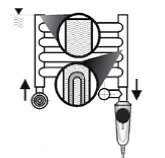
4 INSTALLATION Heater installation. 1. Following the removal of the two-part plastic cover of the head, screw the heater to the bathroom heater, using a suitable spanner (No. 22). A special conical gasket is fitted on the head, allowing the control box to be turned until it faces front. The conical gasket does not require tightening to the end. Usually, two turns are sufficient for the joint to be tight. After screwing the heater in, refit the two-part plastic cover over the head.. If the heater is fitted to a bathroom radiator connected to a central heating system, a heater tee should be used. Suggested installation dual fuel installation electric only - 2 -
5
6 Location In order to set the heating, the thermostat should perform the measurements of ambient temperature most representative for the room. As the detector used for temperature measurement is housed in the enclosure of the thermostat/programming unit, it should be located : - in the central part of the room, - the detector should be fastened to a wall, or placed on the shelf or easily accessible piece of furniture, at the height of ~ 1,50 m, - the detector should be kept away from sources of heat (chimney stack, strong sunlight) and away from draughts (window, door), NOTE: Each object obstructing the way between the programming unit and infrared reception unit housed in the heater enclosure disturbs the transmission. The best communication conditions are provided if the programming unit is located opposite the heater. ~ 1,50 m at least 25 cm - 4 -
7 Starting/Communication test/mounting Starting Lift the programming unit cover by means of a screwdriver. Remove the battery protector, and close the cover (the display will show the readout of the ambient temperature - temperature measured Communication test. The control knob set to symbol depress the pushbutton found on the right hand side for five seconds until H601 1:00 (default settings menu) is displayed. In order to start the communication test, press OK three times. The function CF03 TEST will appear
8 Having selected the mounting position for the programming unit, start for infrared communication test. Whilst the TEST function is displayed, the programming unit (controller) transmits a signal every three seconds to the reception unit (heater). The symbol appears for a while. Make sure that the signalling lamp on the heater flickers with each programming unit signal. Perform this observation for at least one minute. The proper operation of the entire system is guaranteed when the result of the communication test is positive (the signalling lamp on the heater enclosure flickers every three seconds). If the communication is correct, complete the final mounting of the thermostat/programming unit. Two subsequent functions (CF01 and CF02) are additional functions, which may be skipped in this phase. They are described further in this manual. In order to exit the default settings mode (CF 01; CF02; CF03), turn the control knob to any position
9 Mounting Mounting on the wall Open the programming unit cover and remove the batteries. Mount the thermostat by means of screws and bolts ( axes spacing 60 mm). Following programming unit installation, reinsert the batteries paying attention to observe the proper polarity. Close the cover. Mounting on the assembly base (option) Using the assembly base supplied together with the heater, the programming unit may be located on a shelf (see page 4 - Location)
10 OPERATION Setting time Set the control knob to. Days flicker. Press + or - to select, OK to approve and go to the next setting. In order to set minutes, perform the same steps. Turn the control knob to exit settings mode. hours minutes day Temperature adjustment Set the control knob to: - in order to set the mode protecting from freezing (from 5 C to 15 C, default setting 7 C), - in order to set the costeffective mode (from 10 C to 30 C, default setting 15 C), - in order to set the comfort mode (from 10 C to 30 C, default setting 19 C), Press + or - to select. Turn the control knob to exit settings mode
11 TURBO function - drying Setting the time from 30 minutes to four hours. The activation of this mode sets the operation of the heater so that the maximum bathroom heater temperature is maintained over the time programmed. In the automatic mode (AUTO), press the button The TURBO function duration flickers. Press + or - to select the time required (e.g.: 1.30 hour) Press OK to approve. TURBO mode To cancel TURBO function, press C or turn the control knob
12 Programming The heater comes with Comfort program factory set from 6:00 to 23:00, for all days of week. In order to change this setting, set the control knob to PROG. The programming begins from day 1 hour 0:00. Press the pushbutton or in order to program for the specific day the individual periods of cost-effective mode or comfort mode. The first item of hour flickers. hour for specific mark day first mark of hourmark of hour program profile 1-hour cost-effective/ energy-saving 1-hour comfort approval and transfer to next day transfer to next program change Fast programming: In order to apply the same programme in the next day, keep the OK push button depressed for some three seconds until the programme for the next day is displayed. Turn the control knob to exit the programming mode
13 Example: comfort from 6:00 to 8:00 and from 17:00 to 23:00 0h 6h 8h 17h 23h 0h Press until 06:00 appears Press until 23:00 appears Press until 08:00 appears Press until 00:00 appears Press until 17:00 appears approve or approve and copy
14 Automatic mode Set the control knob to AUTO. hours temperature measured selected mode (e.g. comfort) day heating activated absence mode manual mode: comfort or cost-effective/energy-saving (until program change) TURBO mode (from 30 minutes to four hours) During starting, the temperature measured by thermostat is displayed (the symbol appears above C). Press i pushbutton to display the predefined temperature. the temperature displaying sequence may be changed (CF02 menu referring to additional functions, see page 17): - automatic mode: preset temperature - pressing i pushbutton: temperature measured if the user does not wish the operation to be run according to one of the programmes, the user may go to Cost-effective mode (the control knob set to ), Comfort mode or freezing prevention mode, the chosen mode will remain until manually changed
15 Absence mode (leave) In this mode, the temperature may be set (from 5 to 15 C) for the preset period from 1 to 365 days. In the automatic mode AUTO, press the button. The number of days flicker. Press + or -, to set the number of days. Example: leave today, absent for 9 days, press until number 9 flickers. The automatic operation mode will be restored after 9 days at hours. Approve by OK. The temperature flickers. Press + or - to set the temperature. Approve by OK. In order to cancel the absence mode (for example due to earlier return), press C pushbutton or turn the control knob
16 Deviation - manual mode This mode allows the transition from the comfort to cost effectiveness (or other way round) until the next programme change. manual mode selected Example: while in the cost-effective mode, by presing you go to comfort mode. Comfort mode will be switched on untill the mode previously set. In order to cancel the manual mode, press the button again or turn the control knob. Stop mode In order to deactivate heating, set the control knob to. The thermostat will display the ambient temperature. temperature measured
17 Return to default settings The factory set default settings may be restored - the settings made by the installer - date and hour - preset temperatures - default programme. Set the control knob to symbol and keep depressed for 10 seconds the pushbutton found on the left-hand side until the init is displayed. Press OK, to approve or C, to cancel. Return to displaying stop mode. 10 sec
18 Messages transmitted by the signalling lamp: Heating The constant illumination of the signalling lamp on the heater enclosure indicates the operation of the heating element (heating). Faults indication a) flickering of the signalling lamp on the heater enclosure as follows: 2 signals (0,5s.) - break - 2 signals (0,5s.) - break means the indication of the faulty temperature detector in the heater. For repair, the heater should be sent to manufacturer. b) flickering of the signalling lamp as follows: 1 signal (for 0,5s.) - break - 1 signal (for 0,5s.) - break... means that the heater fails to receive the signal from the programming unit. Follow directions contained in Troubleshooting part pages 20 and
19 ADDITIONAL FUNCTIONS The control knob set to symbol. keep depressed for five seconds the pushbutton found on the right hand side until the H601 1:00 is displayed (menu for maintenance, dedicated for installer). press OK. The display will show CF01. CF01 - Adjustment to ambient temperature measurement. If the temperature measured and displayed by the unit is different than the temperature measured by e.g. thermometer, this permits the adjustment of the measurement performed by the detector such that this difference is changed (from -4 C to +4 C with step 0,1 C). CF02 - Option of temperature displaying in the AUTO mode Press + or - in order to select, then press OK, to approve and go to the next menu. constant displaying of ambience temperature temperature displayed constant displaying of preset temperature CF03 - communication test - described in Fastening/Start/Communication test (see page 5)
20 Battery replacement When the sign appears warning that the battery life is coming to an end, the batteries should be replaced within three months (two LR03 or AAA alkaline batteries, 1.5 V). battery consumption rate symbol When replacing the batteries, follow the following precautions: - when inserting the batteries into the unit, observe the correct polarity +/-, - do not dispose of the flat batteries with household rubbish (to protect the environment, bring the worn batteries to the proper collection centre), - do not recharge, - the time for replacing batteries is equal to 45 seconds; after the expiry of this period, the hours are reset (in which case, the hour and date must be set again). Maintenance: Prior to cleaning the heater enclosure the IR heater MUST be disconnected from the elecrticity supply. The enclosures should be cleaned with a damp cloth, with the addition of gentle cleaning agents. NEVER permit the enclosures to get wet
21 Troubleshooting guide With any type of irregularities in the operation of the IR set (heater together with programming unit), we propose, prior to undertaking other measures, to perform the system reset. The heater is controlled by the microprocessor and this is why, in some exceptional circumstances, system reset may be required. To reset the system, it is sufficient to disconnect the heater plug from from mains for the period of one minute, following which the plug should be connected again. Subsequently, run the TEST function (see page 5) in order to check the quality of the communication between the heater and programming unit. When this is completed, enter for setting the required operation mode. If the malfunction to the set continues, check whether the fault is mentioned below and proceed in accordance with the guidelines provided
22 Potential problems with the IR heater: 1. The communication test cannot be made 2. The signalling lamp on the heater enclosure is on but the heater does not heat Check whether the programming unit is operated in the test mode (see page 5), test text is displayed on the display, and the hourglass icon flickers every three seconds in the upper part of the display. Where the infrared controlled units interoperate, it is essential that the transmitter (programming unit) and the reception unit (heater) are adequately aligned. If the problems occur during the communication test, we propose that the operating range be checked by placing the programming unit opposite the heater, at the maximum distance of 6 m. Under such conditions, and where both units (programming unit and heater) are operable, the result of the adequate test must be positive. Subsequently, select the proper place for positioning the programming unit to ensure the perfect communication (test function correctness). If, with the opposite positioning, the heater fails to indicate the reception, the fault is present which may be remedied only by the Manufacturer. The thermal fuse has been damaged (most frequently as a result of the absence of the sufficient water level in the bathroom radiator) or, in exceptional cases, the heating element has been damaged. Both cases require the repairs that can be made only by the Manufacturer
23 3. The heater fails to provide response to the commands issued by the controller, the signalling lamp fails to be illuminated. 4. The signalling lamp on the heater enclosure flickers but the heater fails to heat 5. The position of the controller has changed and the heater fails to respond to the signals from the controller Check the communication by performing communication test again (see page 5) and then proceed in accordance with the guidelines in this manual. Check the indication of faults (see page 16). Where the absence of communication is indicated, check if: - the way between the programming unit and heater is not obstructed in any way. - the programming unit signals that the feeding battery lifetime is about to an end (see page 18) If the fault to the thermistor is signalled, the heater must be sent for a repair. Check the communication quality by performing the test function again (see page 5)
24 Thermostat/programming unit specifications power supply by means of two 1.5V alkaline batteries, type R03 or AAA (delivered with the heater), in normal operation mode the lifetime Is over two years, insulation class III proportional, integral control, time base 10 min, Operating range under unobstructed conditions: 6m. Emission angle : 60 Dimensions: 135 x 81 x 22 mm Protection stage: IP 30 Mounting on wall or assembly base Mounting at the place with average contamination rate Storage temperature: from -10 C to +70 C Operating temperature: from 0 C to +40 C Heater specifications Power supply : 230V/ 50Hz Thermal capacity: according to marking after IR symbol [kw] Insulation class I Maximum operating temperature 60 C +5K Reception angle: 60 Protection stage: IP
25 NOTES: 1. The condition for proper, long-term operation of the heater depends on the total immersion of the heating element in water. 2. The bathroom radiator with the electric heater installed may not be mounted at the distance of less than 60cm from the outlines of the bath or shower (never above the bath or shower). 3.It is recommended that the IR heater installation and first operation is carried out by a qualified fitter. 4. When a bathroom radiator is equipped with valves, during operation with the heater, one of the valves must remain open (temperature expansion of water volume) 5. If a malfunction is found with the heater, the programming unit should be deactivated,. The heater must be disconnected from the electricity supply, and a fitter or the manufacturer should be contacted. 6. Power supply cable irreplaceable. Z type connection. Should the power supply cable become damaged, the heater should be returned to the Manufacturer
26 Guarantee terms and conditions The Manufacturer grants the guarantee for the period of 24 months as of the date of sale, however, not longer than 36 months from the heater s manufacturing date. The faults and defects attributable to the Manufacturer, discovered over this period, will be remedied free of charge or the unit will be replaced with new one, holding the same parameters. Deadline for guarantee claims consideration - up to 14 days as of the date of heater delivery to the Manufacturer. The guarantee does not cover: 1. The use of the product not in conformity with the manual attached. 2. Any and all visible damage to the heating element and programming unit arising from improper use. The damage to the seals of the Manufacturer shall render the guarantee void and invalid. Note: the guarantee card needs to be completed legibly at the retail outlet. Any and all corrections on the guarantee card shall render the guarantee void and invalid
27 GUARANTEE CARD Infrared electric heater type: IR Lot No. : Date of sale: retail outlet seal signature
28 Thank you for purchasing our product! Prior to installation and using this product, familiarization with this manual is necessary. Highly advanced product Application: The heater is dedicated for operation in bathroom heaters Heater selection table Radiator capacity [W] Type of heater IR for 300W IR 0,15 300W 600W IR 0,3 600W 900W IR 0,6 900W 1200W IR 0,9 1200W 1500W IR 1,2 above 1500W IR 1,5 The complete set comprises: The electric heater with the control system (infrared reception unit). Thermostat/ programming unit (infrared transmitter) T-piece (option) Manual
Programmable Towel Radiator Manual
 Programmable Towel Radiator Manual Contents Description Page 3 Location Page 4 Mountings Page 5 Starting Up Page 6+7 Return To The Initial Settings Page 8 Time Setting Page 9 Setting The Temperature (Set-Points)
TYBOX PAC. * _rev1* User guide. Programmable thermostat for heat pumps
 User guide TYBOX PAC Programmable thermostat for heat pumps TYBOX DELTA DORE - Bonnemain 35270 COMBOURG - FRANCE E-mail : deltadore@deltadore.com Device compliant with the requirements of directives: 2004/108/CE
Installation and user manual
 Installation and user manual Please read carefully and retain for future reference Models EcoHeat: C3, C5, C6, C8, C9, C11, C12 Rev.1_09-07-15 Page 1 Table of Contents 1 IMPORTANT: WARNINGS 1.1 GENERAL
WIRELESS WATER CONTROLLER. MC-503RC Installation and Operation Manual
 WIRELESS WATER CONTROLLER MC-503RC Installation and Operation Manual Suitability Suitable for the following Rinnai continuous flow water heaters with Quick Connect cable connector and controllers: Water
RADIO DRIVER. * _Rev.1* User guide. Wireless programmer. RADIO DRIVER zone RADIO DRIVER zones RADIO DRIVER zones
 User guide RADIO DRIVER Wireless programmer 6051117 6051118 6051119 RADIO DRIVER 610-1 zone RADIO DRIVER 620-2 zones RADIO DRIVER 630-3 zones RADIO DRIVER DELTA DORE - Bonnemain - 35270 COMBOURG - FRANCE
Curv-infrared.com. The Smarter Way. To Heat Your Home. Installation & Operating Instructions For Cürv, Flat, Towel Rail and Mirror Infrared Heaters
 Curv-infrared.com The Smarter Way To Heat Your Home Installation & Operating Instructions For Cürv, Flat, Towel Rail and Mirror Infrared Heaters Safety Precautions Important Notice To Purchaser Before
RGR150 USER S MANUAL. Wireless Rain Gauge with Thermometer and Clock
 RGR150 manual-final-091908:layout 1 9/19/08 8:59 AM Page 1 RGR150 USER S MANUAL Wireless Rain Gauge with Thermometer and Clock INTRODUCTION Thank you for selecting this Wireless Rain Gauge. This device
DPC-1 Programmable digital thermostat with communication Versión 2.0. Technical Information. Ref: N
 DPC-1 Programmable digital thermostat with communication Versión 2.0 Ref: N-27360 1108 Technical Information I S O 9 0 0 1 ER-0028/1991 Johnson Controls Manufacturing España, S.L. is participating in the
INSTALLATION MANUAL GUTHD2. Universal Two Way Digital Thermostatic Valve for Shower Systems
 INSTALLATION MANUAL GUTHD2 Universal Two Way Digital Thermostatic Valve for Shower Systems IMPORTANT: To ensure this product is installed properly, you must read and follow these guidelines. The owner/
KTX 1, KTX 2, KTX 3, KTX 4. User Manual Electric Heating KTX 1, KTX 2, KTX 3, KTX 4.
 KTX 1, KTX 2, KTX 3, KTX 4. User Manual Electric Heating KTX 1, KTX 2, KTX 3, KTX 4. en Our products have been designed and manufactured in such a way to ensure that all the quality, functionality and
OWNER S MANUAL DLFCAB / DLFCHB / DLFDAB / DLFDHB High Wall Ductless System Sizes 09 36
 OWNER S MANUAL DLFCAB / DLFCHB / DLFDAB / DLFDHB High Wall Ductless System Sizes 09 36 TABLE OF CONTENTS PAGE SAFETY PRECAUTIONS... 2 GENERAL... 2 INDOOR UNIT PART NAMES... 3 REMOTE CONTROL PART NAMES...
THESE INSTRUCTIONS SHOULD BE READ CAREFULLY AND RETAINED FOR FUTURE REFERENCE.
 TE-700I Installation and Operating Instructions Haverland TOWELS THESE INSTRUCTIONS SHOULD BE READ CAREFULLY AND RETAINED FOR FUTURE REFERENCE. GENERAL RECOMMENDATIONS: * Please read these installation
OWNER S MANUAL. High-Wall Fan Coil Unit CONTENTS
 OWNER S MANUAL High-Wall Fan Coil Unit Page GENERAL 2,3 OPERATING MODES 2 REMOTE CONTROL 2 OPERATION 3-9 REMOTE CONTROL OPERATION 3 INDOOR UNIT DISPLAY 5 EMERGENCY OPERATION 5 PRESSING THE ON/OFF BUTTON
Owner's Manual TABLE OF CONTENTS
 40MB*D Ducted Style Ductless System Sizes 09 to 48 Owner's Manual TABLE OF CONTENTS PAGE A NOTE ABOUT SAFETY... 2 GENERAL... 2 PARTS LIST... 3 DISPLAY PANELS... 4 FUNCTION BUTTONS... 5 REMOTE CONTROL...
Edited by Foxit PDF Editor Copyright (c) by Foxit Software Comp. Programmable digital room thermostat. NEW software! Operating Instructions
 by Foxit Software Comp. Programmable digital room thermostat. NEW software! Operating Instructions") Edited by Foxit PDF Editor Copyright (c) by Foxit Software Comp COMPUTHERM For Evaluation Q7 Only. Programmable digital room thermostat Operating Instructions NEW software! GENERAL DESCRIPTION OF THE THERMOSTAT
Edited by Foxit PDF Editor Copyright (c) by Foxit Software Comp COMPUTHERM For Evaluation Q7 Only. Programmable digital room thermostat Operating Instructions NEW software! GENERAL DESCRIPTION OF THE THERMOSTAT
The most user friendly Security Alarm System L S Section 1 Overview of System Section 2 Planning your Installation
 The most user friendly Contents Section 1 Overview of System 1.1 Kit Contents 1.2 Tools Required 1.3 System Features Security Alarm System L S 4 0 0 Section 2 Planning your Installation 2.1 Location of
TIH 300 S / TIH 400 S / TIH 500 S / TIH 700 S / TIH 900 S / TIH 1100 S
 TIH 300 S / TIH 400 S / TIH 500 S / TIH 700 S / TIH 900 S / TIH 1100 S EN OPERATING MANUAL INFRARED HEATING PANEL TRT-BA-TIH300S-TIH400S-TIH500S-TIH700S-TIH900S-TIH1100S-TC-002-EN Table of contents Notes
OWNER S MANUAL. R 410A Ductless Split System Air Conditioner and Heat Pump
 R 410A Ductless Split System Air Conditioner and Heat Pump Models DLC4(A/H) Outdoor Unit, DLF4(A/H) Indoor Unit Sizes 9K, 12K, 18K, 24K, 30K and 36K Please read the operating instructions and safety precautions
TF1800 Thermofan Installation Guide YOUR STEP-BY-STEP GUIDE TO THE PERFECT INSTALLATION
 ! PLEASE ENSURE YOU HAVE READ AND FULLY UNDERSTOOD THIS GUIDE BEFORE INSTALLATION! TF1800 Thermofan Installation Guide YOUR STEP-BY-STEP GUIDE TO THE PERFECT INSTALLATION BATHROOM FAN HEATERS Introduction
irad Wireless Controller
 irad Wireless Controller The irad Wireless Controller is a wireless (433MHz) programmable thermostat giving high precision room temperature control. It also had a seven day programmer with up to six temperature
/04.14_00. De Longhi Appliances via Seitz, Treviso Italia
 De Longhi Appliances via Seitz, 47 31100 Treviso Italia www.delonghi.com 5711010841/04.14_00 TRDS4 0820E - TRDS4 1025E DRAGON 4 OIL FILLED RADIATOR DESCRIPTION A L M B C D I F G H E N O 2 INSTRUCTIONS
ESRTPRF. Wireless Programmable Room Thermostat, with Delayed & Optimum Start. User and Installation Instructions M/A MANUAL
 M/A MANUAL ESRTPRF Wireless Programmable Room Thermostat, with Delayed & Optimum Start User and Installation Instructions INDEX User Instructions What is a Programmable Room Thermostat? 1 Introduction
s l it l on for Infrared Heaters
 Installation and Instruction Manual for Infrared Heaters Contents Safety and operating instructions... 3 Scope of supply... Installation instructions... 4 5 Initial operation... 10 Cleaning instructions...
User Manual. Electric Heating Element MEG DRY MOA REG 2 REG 3
 User Manual Electric Heating Element MEG DRY MOA REG 2 REG 3 User Manual Our products have been designed and manufactured in such a way to ensure that all quality, functionality and aesthetic requirements
User Manual THR870CUK Programmable Thermostat
 User Manual UK Programmable Thermostat 50051984-001 Rev. A WARNING: This product must be correctly installed and configured to work properly (see pages 20-31). If you are not experienced in wiring electrical
MAKING MODERN LIVING POSSIBLE. TP7001 Range Electronic 7 Day Programmable Room Thermostat. User Guide. Danfoss Heating
 MAKING MODERN LIVING POSSIBLE TP7001 Range Electronic 7 Day Programmable Room Thermostat Danfoss Heating User Guide TP7001 Electronic 7 Day Programmable Room Thermostat For a large print version of these
Smart Temp. Model
 Smart Temp Model 42-160 SINGLE STAGE PROGRAMMABLE THERMOSTAT 1 Heat / 1 Cool Single Stage Thermostat. 5+2 Programmable, Compatible with Gas Heat & Heat Pump System Installation and Operation Manual SPECIFICATIONS:--------------------------------------------------------------------------------
Heat Electric Radiators Installation and Operating Instructions INSTALLER PLEASE NOTE: LEAVE INSTALLATION AND OPERATING INSTRUCTIONS WITH CUSTOMER
 Heat Electric Radiators Installation and Operating Instructions INSTALLER PLEASE NOTE: LEAVE INSTALLATION AND OPERATING INSTRUCTIONS WITH CUSTOMER INSTALLATION AND OPERATION Page 2 1.0 Contents Page 1.0
INSTRUCTIONS. Family 4 N 4062 Issue C Date 01/2011. CMV Certification reference NF205.
 INSTRUCTIONS 412 137 Family 4 N 4062 Issue C Date 01/2011 www.marque-nf.com CMV Certification reference NF205 CONTENTS 1. INTRODUCTION... 3 2. PRESENTATION OF YOUR DUOLIX MAX DOUBLE FLOW UNIT... 3 2.1.
SmartDial. Wireless. User Manual. -en_gb language A004. Document in original
 Wireless Document in original -en_gb language 2017-03-20 A004 Contents 1 Declaration of Conformity... 1 2 Product description... 3 3 Guidelines for installation... 4 4 Operation... 5 5 Interface Description...
Clima Infrared Radiant & Convection Panel
 Clima Infrared Radiant & Convection Panel Model S2030/1 Operating and Instruction Manual Please retain these instructions in a safe place for future reference. Ed. 05112015 cjw 1 References: n 1 min. 50cm
RF Programmable Room Thermostat User Instructions
 ESRTP4RF RF Programmable Room Thermostat User Instructions Thank you for choosing ESi Controls. All our products are tested in the UK so we are confident this product will reach you in perfect condition
Owner s Manual TABLE OF CONTENTS
 40MBDQ Ducted Style Ductless System Sizes 18 to 48 Owner s Manual TABLE OF CONTENTS PAGE A NOTE ABOUT SAFETY... 2 GENERAL... 2 PARTS LIST... 3 DISPLAY PANELS... 4 FUNCTION BUTTONS... 5 REMOTE CONTROL...
Design Manual Installation Operation Maintenance
 Design Manual Installation Operation Maintenance Model FT194 UV/IR Portable Flame Detector Test Lamp 23282 Mill Creek Drive, Suite 215 Laguna Hills, CA 92653 USA +1.949.583.1857 Phone +1.949.340.3343 Fax
OWNER'S MANUAL R-410A Duct Free Split System Air Conditioner and Heat Pump
 R-10A Duct Free Split System Air Conditioner and Heat Pump Product Family: DFF(A/H)H, DFC(A/H) Please read the operating instructions and safety precautions carefully and thoroughly before installing and
User Instructions for Remote Controlled 2kW Rotisserie Effect Fan Heater Model 1276
 200662_2 Page 1 User Instructions for Remote Controlled 2kW Rotisserie Effect Fan Heater Model 1276 These instructions should be read carefully and retained for future reference. Important Notes These
Portable Refrigerator
 Portable Refrigerator Owners Manual Single door 40 litre 65 litre 80 litre 125 litre Double door 74 litre 95 litre 2009 Introduction The National Luna range of portable fridges and freezers are high-performance,
Digital Electronic Thermostat With RF
 Digital Electronic Thermostat With RF Instruction Manual Model No RT300RF PRODUCT COMPLIANCE This product complies with the essential requirements of the following EC Directives: Electro-Magnetic Compatibility
Owner's Manual TABLE OF CONTENTS
 40MAQ High Wall Ductless System Sizes 09 to 36 Owner's Manual TABLE OF CONTENTS PAGE A NOTE ABOUT SAFETY... 2 GENERAL... 2 PART NAMES... 3 FUNCTION BUTTONS... 4 DISPLAY PANELS... 5 REMOTE CONTROL... 6
Owner s Manual TABLE OF CONTENTS
 40GVC / 38GVC 40GVQ / 38GVQ High---Wall Ductless plit ystem izes 009 --- 024 Owner s Manual TABLE OF CONTENT PAGE AFETY PRECAUTION... 2 GENERAL... 2 INDOOR UNIT PART NAME... 3 REMOTE CONTROL PART NAME...
Owner s Manual TABLE OF CONTENTS
 40MBD / 38MAQ / 38MBQ Ducted tyle Ductless plit ystem izes 09 to 48 Owner s Manual TABLE OF CONTENT PAGE A NOTE ABOUT AFETY... 2 GENERAL... 2 PART LIT... 3 DIPLAY PANEL... 4 REMOTE CONTROL... 6 REMOTE
SRT321 User and Installation Instructions
 SRT321 User and Installation Instructions Electronic Room Thermostat & Temperature Sensor (Tx) - Z-Wave 1 2 The SRT321 is a wireless electronic battery powered room thermostat that uses interoperable two-way
CM921 - User Guide 1 day Wireless Programmable Room Thermostat with LoT technology
 Description The Honeywell CM921 is a wireless programmable room thermostat designed to control you heating system efficiently, providing comfortable temperatures when you are at home and energy savings
Digital Room Thermostat
 Digital Room Thermostat Instruction Manual Model No RT500 PRODUCT COMPLIANCE This product complies with the essential requirements of the following EC Directives: Electro-Magnetic Compatibility directive
CentaurStat 7 User Operating Instructions Central Heating Programmable Room ThermoStat
 CentaurStat 7 User Operating Instructions Central Heating Programmable Room ThermoStat The Centaurstat 7 is a programmable room thermostat that provides precise temperature control from a single point
PROGRAMMABLE 7-DAY THERMOSTAT
 PROGRAMMABLE 7-DAY THERMOSTAT Installation and user instruction This instructions to be retained by the user 1 Thank you for choosing Riello s weekly programmer.. This central heating control device is
KNX module for smoke alarm devices Dual/VdS and Q-Label (Order no )
") Product definition KNX module for smoke alarm devices Dual/VdS and Q-Label (Order no 2343 00) Art. no 2343 00 Page 1 of 22 Product definition Table of contents 1 Product definition... 3 1.1 Product catalogue...
Product definition KNX module for smoke alarm devices Dual/VdS and Q-Label (Order no 2343 00) Art. no 2343 00 Page 1 of 22 Product definition Table of contents 1 Product definition... 3 1.1 Product catalogue...
JS. Bosch Remote Control
 6720606990-00.1JS Bosch Remote Control For: GWH 635 ES/635 ESO/250SX/250SXO/2400E /2400EO/2400ES/2700ES/715ES/C800ES/C920ES /C920ESC/EVOLUTION 500/INTEGRA 500/C1210ES /C1210ESC/C1050ES/C950ES/940ES/940ESO/830ES
Contents. References for your electric towel-dryer radiator 2. Warning 3
 Contents References for your electric towel-dryer radiator 2 Warning 3 Installation 1/Prepare to install the electric towel-dryer radiator 4 2/Mark and drill the fixing points for the electric towel-dryer
Digital Electronic Thermostat With RF
 RT300RF Manual:89 6/7/10 12:52 Page 1 Digital Electronic Thermostat With RF Instruction Manual Model No RT300RF 2 RT300RF Manual:89 6/7/10 12:52 Page 2 2 RT300RF INSTRUCTION MANUAL RT300RF Manual:89 6/7/10
Colorado SCR. Electric Towel Radiator Operating and Installation Instructions. (Read these instructions carefully and retain for future reference)
") Colorado SCR Electric Towel Radiator Operating and Installation Instructions (Read these instructions carefully and retain for future reference) Models SCR 300 300W SCR 450 450W SCR 750 750W NOTE A qualified
Colorado SCR Electric Towel Radiator Operating and Installation Instructions (Read these instructions carefully and retain for future reference) Models SCR 300 300W SCR 450 450W SCR 750 750W NOTE A qualified
DIGISTAT PROGRAMMABLE 24 HOUR ROOM THERMOSTAT SYSTEM. Radio frequency controlled programmable room thermostat.
 ROOM THERMOSTAT SYSTEM Radio frequency controlled programmable room thermostat. LARGE RECEIVER: 24CDi, 26CDi Xtra, 28CDi, 35CDi Mk I and 35CDi Mk II SMALL RECEIVER: 24i Junior, 28i Junior and Si Mk II
Installation and Operating Manual
 Installation and Operating Manual SR868C6 System Regulator for Solar Thermal Systems Display Panel Illustration Pos. Button on display panel Button description 1 Green lamp Power indication lamp 2 On/Off
48 TAYLOR CEILING FAN
 48 TAYLOR CEILING FAN Owner s Manual Models #20554 If a problem cannot be remedied or you are experiencing difficulty in installation, please contact the Service Department: 1-877-459-3267, 9 a.m.- 5 p.m.
Model: RT310RF. Installation Manual
 Model: RT310RF Installation Manual Contents Product Compliance... 3 Safety Information... 3 Box Content... 3 Introduction... 4 Features... 5 Installation... 5 Button functions and keys... 7 Installer mode...
VMH 09/12/18/24 SD Series Inverter Single Zone Ductless Mini-Split
 REMOTE CONTROLLER MANUAL VMH 09/12/18/24 SD Series Inverter Single Zone Ductless Mini-Split Heat Controller 1900 Wellworth Ave. Jackson, MI 49203 (517)787-2100 www.heatcontroller.com VMH 09,12,18,24 SD
DIGISTAT OPTIMISER PROGRAMMABLE 7 DAY ROOM THERMOSTAT SYSTEM. Radio frequency controlled programmable room thermostat
 DIGISTAT OPTIMISER PROGRAMMABLE 7 DAY ROOM THERMOSTAT SYSTEM Radio frequency controlled programmable room thermostat FOR GREENSTAR 25 HE and GREENSTAR 30 HE MODELS Hol Man Auto Day SIGNAL HEATING ON OVERRIDE
Easy-Stat. Wireless Programmable Room Thermostat Pt No
 Easy-Stat Wireless Programmable Room Thermostat Pt No 7.2000050 1 Installing the receiver The receiver must be installed into the boiler control panel, refer to the boiler installation manual for guidance.
Desktop Dual-band Radio Controlled Clock with Melody Alarm and Backlight Model: RM926 User Manual
 Desktop Dual-band Radio Controlled Clock with Melody Alarm and Backlight Model: RM926 User Manual CONTENTS Introduction... 1 Product Overview... 2 Front View... 2 Back View... 2 LCD Display... 3 Safety
Digital Thermometer with Ice Alert and Clock
 Digital Thermometer with Ice Alert and Clock Model: RAR381 USER MANUAL Specifications... 8 About Oregon Scientific... 8 EU-Declaration of Conformity... 9 FCC Statement... 9 Declaration of Conformity...
Tebis application software
 5 Tebis application software STG51x Radio smoke detector STG54x Radio heatstroke Electrical / Mechanical characteristics: see product information Product reference Designation ETS version TP device RF
AUTO CM CM USER GUIDE
 1 2 3 4 5 6 7 AUTO CM701...2-6 CM707...7-11 USER GUIDE CM701 - USER GUIDE Description The Honeywell CM701 is a programmable room thermostat designed to control your heating system efficiently, providing
User manual AG-WT10. Indoor unit air/air heat pump UHB GB
 User manual Indoor unit air/air heat pump UHB GB 1516-1 331557 Table of Contents 1 Important information Installation data Safety information Serial number an excellent choice Safety instructions Recovery
CentaurPlus C27 Series 2 User Operating Instructions
 CentaurPlus C27 Series 2 User Operating Instructions Two Channel Central Heating and Hot Water r The Horstmann CentaurPlus C27 two channel programmer gives independent control over hot water and heating
CS027 User Instructions
 CS027 User Instructions Battery Powered 7 Day Programmable Room Thermostat Programmable room thermostats are widely recognised as one of the best ways in which to control central heating. The CS027 programmable
PROGRAMMABLE 7-DAY RF THERMOSTAT
 PROGRAMMABLE 7-DAY RF THERMOSTAT Installation and user instruction This instructions to be retained by the user 1 Thank you for choosing Beretta s radio frequency (RF) Radiostat. This central heating control
Honeywell. Wireless Rain Gauge with Indoor. Temperature (TC152) USER MANUAL TABLE OF CONTENTS INTRODUCTION 3 PRODUCT OVERVIEW 4 REMOTE RAIN GAUGE 7
 USER MANUAL TABLE OF CONTENTS INTRODUCTION 3 PRODUCT OVERVIEW 4 REMOTE RAIN GAUGE 7") TABLE OF CONTENTS INTRODUCTION 3 PRODUCT OVERVIEW 4 REMOTE RAIN GAUGE 7 BEFORE YOU BEGIN 9 BATTERY INSTALLATION 10 LOW BATTERY WARNING 11 HOW TO USE THE TABLE STAND 11 GETTING STARTED 11 Honeywell Wireless
TABLE OF CONTENTS INTRODUCTION 3 PRODUCT OVERVIEW 4 REMOTE RAIN GAUGE 7 BEFORE YOU BEGIN 9 BATTERY INSTALLATION 10 LOW BATTERY WARNING 11 HOW TO USE THE TABLE STAND 11 GETTING STARTED 11 Honeywell Wireless
Operating Guide: for the Warmup tempo Digital Programmable Thermostat Part of the Element Series Introduction
 Operating Guide: for the Warmup tempo Digital Programmable Thermostat Part of the Element Series Introduction The tempo has been designed with simplicity in mind and is highly intuitive in its programming.
Room Sensor [RBT-3C] Installation Instructions
![Room Sensor [RBT-3C] Installation Instructions](/thumbs/78/77725494.jpg "Room Sensor [RBT-3C] Installation Instructions") Room Sensor [RBT-3C] Installation Instructions Room Sensor to replace existing wired room thermostat. Provides programmer / time clock functionality. Requires Network OWL to operate. IN THE BOX: Room Sensor
Room Sensor [RBT-3C] Installation Instructions Room Sensor to replace existing wired room thermostat. Provides programmer / time clock functionality. Requires Network OWL to operate. IN THE BOX: Room Sensor
Caution: To maintain compliance with the RF exposure guidelines, place the unit at least 20cm from nearby persons.
 Installation Guide: for the Warmup Tempo Digital Programmable Thermostat The world s best-selling floor heating brand Introduction The Tempo thermostat is designed to aid in the comfort of your home by
MODULAR AUTOMATIC GRANULAR ICE FLAKER
 MODULAR AUTOMATIC GRANULAR ICE FLAKER INSTRUCTIONS AND WARNINGS 24479 rev. 03 It is strictly forbidden to reproduce this instruction manual or any part thereof. Dear Customer, Congratulations on having
The Vitro-i. Radiant / Convector Combination Heater. Instructions for Operation and Installation
 E1400250 The Vitro-i Radiant / Convector Combination Heater Instructions for Operation and Installation (Read these instructions carefully and retain for further reference.) Models: Vitro-i 750 Black Vitro-i
Motion tracking. sensor led light. Installation & operating manual NIGHTWATCHER. Model no: nw1200x
 Motion tracking sensor led light Installation & operating manual NIGHTWATCHER Model no: nw1200x 1 INTRODUCTION Congratulations on the purchase of your new Nightwatcher Security Light. Before installation
ECO AND DATE /06 ARTWORK DESCRIPTION. 22 page A6 : Saddle stitch (2-wire) 6 page : 4 colour : 170gsm Silk 18 page : 1 colour : 100gsm Silk
 6 page : 4 colour : 170gsm Silk 18 page : 1 colour : 100gsm Silk") DRAWING DETAILS PART NUMBER 42011077-103 ISS R1 ECO AND DATE 0024168 08/06 ARTWORK DESCRIPTION CM921 USER GUIDE BOOKLET (UK - English) DRAWN MKTING MF BM DATE 08/06 BOOKLET DETAILS SPECIFICATION COVER
DRAWING DETAILS PART NUMBER 42011077-103 ISS R1 ECO AND DATE 0024168 08/06 ARTWORK DESCRIPTION CM921 USER GUIDE BOOKLET (UK - English) DRAWN MKTING MF BM DATE 08/06 BOOKLET DETAILS SPECIFICATION COVER
MOBILE CALL GSM Alarm System User s Manual
 MOBILE CALL GSM Alarm System User s Manual Profile For a better understanding of this product, please read this user manual thoroughly before using it. Contents Function Introduction (3) Alarm Host Diagram
OPERATING MANUAL Enertronic Control System 2
 OPERATING MANUAL Enertronic Control System 2 The integrated control system for Lennox chillers in the Ecologic range Manufacturer: Lennox Benelux B.V. Postbus 1028, 3860 BA NIJKERK Watergoorweg 87, 3861
SP16. 08/50740/1 (UK) - Issue 1
 - Issue 1") SP16 08/50740/1 (UK) - Issue 1 The product complies with the European Safety Standards EN60335-2-30 and the European Standard Electromagnetic Compatibility (EMC) EN55014, EN60555-2 and EN60555-3 These
SP16 08/50740/1 (UK) - Issue 1 The product complies with the European Safety Standards EN60335-2-30 and the European Standard Electromagnetic Compatibility (EMC) EN55014, EN60555-2 and EN60555-3 These
ST9400S User Guide. 1 Day Programmer, 2 channel With Boiler Service Reminder / Shut-down Feature
 PLEASE RESPECT YOUR ENVIRONMENT! Take care to dispose of this product and any packaging or literature in an appropriate way WHAT IS A PROGRAMMER?...an Explanation for Householders (as recommended by the
Operating instructions
 MA00929301 09/2015 Operating instructions ED10429002 ESYLUX GmbH An der Strusbek 40 22926 Ahrensburg Germany info@esylux.com www.esylux.com 1 Table of contents 1 Using the manual 8 2 Safety instructions
airooncentre.co.uk irconcentre.co.uk Xpelair Low Energy Wall/Window Fan Range GX6 EC2 GXC6 EC2 Quick Order Hotline or
 Xpelair Low Energy Wall/Window Fan Range GX6 EC2 GXC6 EC2 Installation and Maintenance Instructions Retain for future reference 3. To remove the impeller, unscrew the central screw with a 7mm nut runner
CM707. Programmable Room Thermostat with Optimum Start, Optimum Stop and Delayed Start. User Guide
 CM707 Programmable Room Thermostat with Optimum Start, Optimum Stop and Delayed Start User Guide WHAT IS A PROGRAMMABLE ROOM THERMOSTAT? An explanation for householders... A programmable room thermostat
ivector HEATER/COOLER 2 AND 4-PIPE MODELS.
 25278 ivector Installation Guide US 02/01/2013 09:24 Page 2 ivector HEATER/COOLER 2 AND 4-PIPE MODELS. INSTALLATION, OPERATING, MAINTENANCE & AFTER SALES MANUAL JANUARY 2013, ISSUE 1 Product Serial Number:
OWNER S MANUAL ENGLISH REMOTE CONTROLLER R05 YDS-R
 ENGLISH YDS-R05-0408 OWNER S MANUAL REMOTE CONTROLLER R05 Please read this installation manual carefully before installing your air conditioner. Please keep this manual in a safe place for future reference.
Detailed operating instructions
 MA00613903 Detailed operating instructions MD 360/8 Basic EB10430404 MD 360i/8 Basic EB10430428 MD 360/24 Basic EB10430848 MD 360i/24 Basic EB10430862 MD 360/8 Basic SMB EB10430497 MD 360i/8 Basic SMB
L. Terminal block Connecting Label:
 TABLE OF CONTENT A. Installation and Mounting.. 3 1. Installation 3 2. Wiring... 4 3. Mounting.. 5 B. Key Interface. 7 C. LCD Interface...8 D. Start/Reset...9 E. Operation Mode.10 F. Time Setting Mode.11
User manual AG-WT10. Indoor unit air/air heat pump UHB GB LEK
 LEK User manual Indoor unit air/air heat pump UHB GB 1715-3 331557 Table of Contents 1 Important information Installation data Safety information Serial number an excellent choice Safety instructions
Spa Touch Control Panel with BP2100, BP6013 spa controllers. (Spa Owner s Manual insert)
") Spa Touch Control Panel with BP2100, BP6013 spa controllers. (Spa Owner s Manual insert) P.N. 7876C (export) February 12, 2015 For Spas equipped with BP2100, BP6013 controllers and Spa Touch panel. Spa
Spa Touch Control Panel with BP2100, BP6013 spa controllers. (Spa Owner s Manual insert) P.N. 7876C (export) February 12, 2015 For Spas equipped with BP2100, BP6013 controllers and Spa Touch panel. Spa
Ambient Weather WS-0211 Wireless Wendy the Weather Wizard User Manual
 Ambient Weather WS-0211 Wireless Wendy the Weather Wizard User Manual Table of Contents 1. Introduction... 2 2. Getting Started... 2 2.1 Parts List... 2 2.2 Recommend Tools... 2 2.3 Thermometer Sensor
ET4 heat/cool day RF programmable room thermostat. ET4 Receiver
 TFC GROUP LLP Programmable RF Room Thermostat ET4 ET4 heat/cool 5+1+1 day RF programmable room thermostat 1 N 2 ET4 Receiver L L Supply Live N Supply Neutral 1 Live Return 2 Live Feed 20V AC 50Hz 24 240V
Security GSM Alarm System
 Security GSM Alarm System USER MANUAL 4 wired and 6 wireless defense zones; Can preset and store 6 voice phones and 3 message phones; Remote two-way intercom; Telephone (mobile phone) remote control programming;
* _rev1* User guide DRIVER 230 CPL. 3 zone weekly programmer using power line carriers
 User guide DRIVER 230 CPL 3 zone weekly programmer using power line carriers DELTA DORE - Bonnemain 35270 COMBOURG - FRANCE E-mail : deltadore@deltadore.com Device complying with the requirements of the
40KMC KMQ
 40KMC------301 40KMQ------301 OWNER S MANUAL Split system Global cassette indoor unit IR Remote Control Room Controller Zone Manager The unit can be used with infrared Remote Control, with the Carrier
Telephone Helpline: (Australia) Blast Chiller / Freezer. Instruction Manual. Model DN492-A DN494-A
 Blast Chiller / Freezer. Instruction Manual. Model DN492-A DN494-A") Blast Chiller / Freezer Instruction Manual Model DN492-A DN494-A 1 Safety Tips Position on a flat, stable surface. A service agent/qualified technician should carry out installation and any repairs if
Blast Chiller / Freezer Instruction Manual Model DN492-A DN494-A 1 Safety Tips Position on a flat, stable surface. A service agent/qualified technician should carry out installation and any repairs if
Digital Thermometer with Ice Alert and Radio-Controlled Clock. Model: RMR382 USER MANUAL CONTENTS
 Digital Thermometer with Ice Alert and Radio-Controlled Clock CONTENTS Model: RMR382 USER MANUAL Ice Warning... 7 Hi / Lo Temperature Alarm... 7 Reset... 8 Precautions... 8 Specifications... 8 About Oregon
Control solutions Biofloor
 TEF234 Electronic room thermostat with display 230V & 24V COMAP proposes a new control system for heating and cooling underfloor. Consisting of a 6 or 10- channels controller (MCF234), analogic (TAF234)
Digital Thermometer with Ice Alert and Radio-Controlled Clock Model: RMR682
 Digital Thermometer with Ice Alert and Radio-Controlled Clock Model: RMR682 CONTENTS USER MANUAL Ice Warning... 8 Hi / Lo Temperature Alarm... 8 Reset... 8 Precautions... 8 Specifications... 9 About Oregon
SAS908WHB-3-RF/B WIRELESS THERMOSTAT
 SAS908WHB-3-RF/B WIRELESS THERMOSTAT Installation and operation instructions 908WHB-3-RF/B can replace most common residential thermostat and is designed to be used with electric, gas or oil heating control
360º Surface Mount Ceiling PIR Light Controller
 360º Surface Mount Ceiling PIR Light Controller Model: PDRS1500 Installation & Operating Instructions 1 1. General Information These instructions should be read carefully and retained for further reference
USER MANUAL TUNGSTEN SMART-HEAT ELECTRIC WIRELESS DIMMER CONTROLLER BY BROMIC IMPORTANT
 TUNGSTEN SMART-HEAT ELECTRIC WIRELESS DIMMER CONTROLLER BY BROMIC USER MANUAL Version 1.0 Doc. T744.01_EN (TEMP) TVHET916A07BK IMPORTANT READ THIS MANUAL CAREFULLY. SEE INSIDE COVER FOR IMPORTANT INFORMATION
OWNER S MANUAL HIGH WALL INVERTER. (English) (BSHVD1S SERIES)
 (BSHVD1S SERIES)") OWNER S MANUAL HIGH WALL INVERTER (English) (BSHVD1S SERIES) IMPORTANT As with any product that has moving parts or is subject to wear and tear, it is VERY IMPORTANT that you maintain your air conditioner
OWNER S MANUAL HIGH WALL INVERTER (English) (BSHVD1S SERIES) IMPORTANT As with any product that has moving parts or is subject to wear and tear, it is VERY IMPORTANT that you maintain your air conditioner