TM: MCCKCM - W B. Fan Coil Units. Models: MWM-FW Series MCM-DW Series MCK-AW/BW Series MCC-CW Series MDB-BW Series
|
|
|
- Stella Gallagher
- 5 years ago
- Views:
Transcription

1 TM: MCCKCM - W B Fan Coil Units Models: MWM-FW Series MCM-DW Series MCK-AW/BW Series MCC-CW Series MDB-BW Series
2 Contents Features... 1 Specifications... 3 Unit Selection Procedure Cooling Capacity Performance Chart Heating Capacity Performance Chart Water Flow Rate Vs Pressure Drop Correction Factors Wiring Diagrams Controllers Blower Performance Curves Outlines And Dimensions General Installation Guide General Operation Guide Note: Installation and maintenance are to be performed only by qualified personnel who are familiar with local codes and regulations, and experienced with this type of equipment. Caution: Sharp edges and coil surfaces are a potential injury hazard. Avoid contact with them. Warning: Moving machinery and electrical power hazards. May cause severe personal injury or death. Disconnect and lock off power before servicing equipment. "McQuay" is a registered trademark of McQuay International. All rights reserved throughout the world McQuay International "Bulletin illustrations cover the general appearance of McQuay International products at the time of publication and we reserve the right to make changes in design and construction at any time without notice."
3 Features Space Saving Different types of fan coil units are designed to be both versatile and space saving to suit every interior design. Ceiling concealed type for the sophisticated, luxurious floor space saving, all kind of interior decoration; ceiling exposed type for economical and space saving installation; etc. Zone Control These fan coil units can be installed in different zones as each unit operates independently. Zone control on energy saving, different comfort requirement; better air distribution needs can therefore be easily achieved. Unique Features For MWM-FW Series Easy Installation The wall mounted fan coil unit is easily installed because of its compact size, slimness and light weight. Slim and short outdoor unit can be easily installed even in a narrow balcony and passageway and yet have a stable profile. Space Saving No space is required on either floor or ceiling. This newly developed super slim design for wall mounting maximises floor space usage and enhance ceiling appearance where ceilings are low. Quiet Operation Cooling comfort is improved by whisper-quiet operation which is achieved by a tangential fan. Excellent Air Distribution Air discharge direction can be adjusted in four directions, manually or automatically by using LCD remote control, coupled with good air flow, the unit provides excellent air distribution. Facilitated Maintenance Ensured The new design cassette filter is slide-out type which can be easily removed at the air inlet grille for cleaning. Maintenance is easy for electrical components, piping and wiring as these are all easily accessible by merely removing front plastic panel. Wireless Remote Control The compact LCD transmitter is able to operate the air conditioner unit within the distance of 9 meters. Fan motor speed can be set at low/medium/high or automatic.sleep mode automatically increase set temperature since room temperature is lower at night thus achieving comfort surrounding. Air flow direction can be controlled automatically. Room temperature is controlled by electronic thermostat. The unit can be preset to on and off automatically for maximum of 15 hours by using timer on/off. Slit Fin The unique Hydrophilic slit fin has greatly improved the air flow and the contact surfaces with the air thus to boost the cooling capacity. 1
4 Unique Features For MCK-AW/BW Series Built In High Head Drain Pump The unit comes with a built in high head drain pump. Condensate water can be pumped up to 500mm and drain out smoothly. 4-Way Air Discharge And Air Swing These features greatly improve the air distribution in the conditioned space. Wireless And Wired Controller Option Wireless Handset is the standard controller. However if wired controller required, Netware wired controller is a wise choice(optional). Unique Features For MCM-DW Series 2-Way Air Discharge And Air Swing The 2-way air discharge couple with the air swing function, provide better air distribution in the conditioned space. Easy Maintenance The air filter and components can be easily accessed from the bottom of the unit. This make servicing and maintenance become a simple task. Wireless And Wired Controller Option Wireless Handset is the standard controller. However if wired controller required, Netware wired controller is a wise choice(optional). Unique Features For MCC-CW Series Elegance And Prestige As the unit is installed above the ceiling with only the supply and return air grille exposed to view, the air conditioned space will appear as elegant and prestigious as a centralized air conditioned area. Evergreen Design This unit will never become obsolete as the unit is completely concealed away. Interior decoration for maximum aesthetic beauty as well as interior design is easily achieved. Superior Air Distribution As the conditioned air can be distributed to every corner of the area by air duct, this will ensure more pleasant living environment, thus provide extra comfort to the occupants. Optional Duct Accessories The optional duct accessories makes the ducting and installation work so easy. Optional Wired Controller Optional Netware wired controller offers simple and flexibility in controlling the unit. Unique Features For MDB-BW Series Superb Air Distribution These units are designed with high air flow and static, enables adequate distribution of air to the desired space. Providing comfort to every corner of the room. Reliability The structures are strong and robust to ensure the product operation life. Versatile Multiple rooms can be cooled together by just using one unit of MDB. 2
5 Specifications MWM MODEL 005FW 007FW 010FW 015FW 020FW 025FW PERFORMANCE High 300 / / / / / / 274 Air Flow (CFM / L/s) Medium 230 / / / / / / 229 Low 190 / / / / / / 179 kcal/hr Nominal Total Cooling Capacity W Btu/hr kcal/hr Sensible Cooling Capacity W Btu/hr Nominal Total Heating Capacity kcal/hr (Entering water Temp. : 60 C) W Btu/hr Water Flow Rate USGPM / LITRES/M 1.10 / / / / / / Head Loss (Cooling) psi / Pa / / / / / / Head Loss (Heating) : 60 C psi / Pa / / / / / / COIL Type Tube Fin Connection Seamless copper tube mechanically boded to aluminium slit fin. OD 7mm, thickness 0.35 mm. thickness 0.11 mm OD 1/2" copper tube Number of rows / fin per inch 1 / 18 1 / 20 2 / 18 2 / 18 2 / 18 2 / 18 Max. Working Pressure (kg/cm 2 ) / (psi) 16.4 / 233 Testing Pressure 30 kg/cm 2 for 1 min, leak test : 16 kg/cm 2 for 5 min. Surface Area m 2 / ft / / / / / / Surface Air Velocity (m/s) / (ft/min) / / / / / / MOTOR Type Power Supply V/Ph/Hz Permanent split capacitor motor / 1 / 50, / 1 / 60 Rated Input power W (50/60Hz) / / / / 81 Rated Running Current A (50/60Hz) / / / / 0.38 Poles 4 High Fan Sound Level (dba) Medium Fan Low Fan Room Temp. Micro-computer Controlled Thermostat Control Air Discharge Operation Automatic Louver (Up & Down) LCD wireless micro-computer remote control Condensate Drain Size mm AIR FILTER Washable Saran Net Filter WEIGHT kg DIMENSION (H x W x D) mm 290 x 815 x x 1062 x 202 Condition Cooling capacity Heating capacity : Entering air temp. : 26.7 C ( 80 F ) DB, 19.4 C ( 67 F ) WB Entering water temp. : 7.2 C ( 45 F ) Leaving water temp. : 12.8 C ( 55 F ) : Entering air temp. : 21.1 C ( 64 F ) DB Entering water temp. : 60 C ( 140 F ) Leaving water temp. : 55 C ( 131 F ) Microphone position : 1m in front of the unit & 0.8m below the vertical centre line of the unit. (JIS C 9612) 3
6 MCK MODEL 020AW 025AW 030AW 040AW 050AW PERFORMANCE High 770 / 1, / 1, / 1,560 1,020 / 1,740 1,080 / 1,840 Air Flow (CFM/CMH) Medium 650 / 1, / 1, / 1, / 1, / 1,680 Low 630 / 1, / 1, / 1, / 1, / 1,540 kcal/hr 6,048 6,804 7,964 9,073 9,829 Nominal Total Cooling Capacity W 7,034 7,913 9,261 10,551 11,430 Btu/hr 24,000 27,000 31,600 36,000 39,000 kcal/hr 4,209 4,738 5,494 6,162 6,628 Sensible Cooling Capacity W 4,894 5,510 6,389 7,166 7,708 Btu/hr 16,700 18,800 21,800 24,450 26,300 Nominal Total Heating Capacity kcal/hr 9,451 10,585 12,198 13,584 14,365 (Entering water Temp. : 60 C) W 10,991 12,309 14,185 15,797 16,706 Btu/hr 37,500 42,000 48,400 53,900 57,000 Water Flow Rate USGPM / LITRES/M 5.32 / / / / / Head Loss (Cooling) psi / Pa 2.13 / 14, / 21, / 30, / 50, / 75,773 Head Loss (Heating) : 60 C psi / Pa 1.70 / 11, / 17, / 24, / 41, / 63,459 COIL Type Tube Fin Connection Seamless copper tube mechanically bonded to aluminium slit fin OD 9.52 mm, thickness 0.35 mm Thickness 0.11 mm OD 3/4" copper tube Number of rows / fin per inch 2/12 2/14 2/16 2/16 2/16 Max. Working Pressure (kg/cm 2 ) / (psi) 16.4 / 233 Testing Pressure 30 kg/cm 2 for 1 min, leak test : 16 kg/cm 2 for 5 min Surface Area m 2 / ft / / / / / Surface Air Velocity (m/s) / (ft/min) 0.78 / / / / / MOTOR Type Power Supply V/Ph/Hz Permanent split capacitor motor / 1 / 50, /1/60 Rated Input W 127 / / / / / 328 Running Current A 0.53 / / / / / 1.50 Poles 6 Room Temp. Micro-computer Controlled Thermostat Control Air Discharge Operation Automatic Louver (Up & Down) LCD wireless micro-computer remote control Condensate Drain Size mm AIR FILTER Washable Saran Net Filter WEIGHT (Unit + panel) kg DIMENSION (H x W x D) mm 335 x 820 x 820 ( 363 x 930 x 930 ) Condition Cooling capacity Heating capacity : Entering air temp. : 26.7 C (80 F)DB, 19.4C (67 F)WB Entering water temp. : 7.2 C (45 F) Leaving water temp. : 12.8 C (55 F) : Entering air temp. : 21.1 C (64 F)DB Entering water temp. : 60 C (140 F) Leaving water temp. : 55 C (131 F) 4
7 MCK MODEL 015BW 020BW 025BW 030BW PERFORMANCE High 430 / / / / 287 Air Flow (CFM / L/s) Medium 370 / / / / 253 Low 310 / / / / 224 kcal/hr Nominal Total Cooling Capacity W Btu/hr kcal/hr Sensible Cooling Capacity W Btu/hr Nominal Total Heating capacity kcal/hr (Entering water Temp. : 60 C) W Btu/hr Water Flow Rate USGPM/LITRES/M 3.34 / / / / 25 Head Loss (Cooling) psi / Pa / / / / Head Loss (Heating) : 60 C psi / Pa / / / / COIL Type Tube Fin Connection Seamless copper tube mechanically bonded to aluminium slit fin. OD 9.52 mm, thickness 0.35 mm. thickness 0.11 mm OD 3/4" copper tube Number of rows / fin per inch 1 / 18 2 / 14 2 / 14 2 / 14 Max. Working Pressure (kg/cm 2 )/(psi) 16.4 / 233 Testing Pressure 30 kg/cm 2 for 1 min, leak test : 16 kg/cm 2 for 5 min. Surface Area m 2 /ft / / / / Surface Air Velocity (m/s)/(ft/min) / / / / MOTOR Type Power Supply V/Ph/Hz Permanent split capacitor motor / 1 / 50, / 1 / 60 Rated Input power W (50/60Hz) 72 / / / / 108 Rated Running Current A (50/60Hz) 0.31 / / / / 0.50 Poles 6 Sound pressure level ( dba ) High Fan Medium Fan Low Fan Room Temp. Micro-computer Controlled Thermostat Control Air Discharge Operation Manual Louver LCD wireless micro-computer remote control Condensate Drain Size mm AIR FILTER Washable Saran Net Filter WEIGHT (Unit + Panel) kg DIMENSION - HxWxD ( ) - with panel mm 293 x 650 x 650 (363 x 930 x 930) Condition Cooling capacity Heating capacity : Entering air temp. : 26.7 C ( 80 F ) DB, 19.4 C ( 67 F ) WB Entering water temp. : 7.2 C ( 45 F ) Leaving water temp. : 12.8 C ( 55 F ) : Entering air temp. : 21.1 C ( 64 F ) DB Entering water temp. : 60 C (140 F) Leaving water temp. : 55 C (131 F) Microphone position : MCK B - 1.4m below the facia (JIS C 9612), MCK030B - 1.5m below the facia (JIS B 8615). 5
8 MCM MODEL 020DW 025DW 030DW 040DW 050DW PERFORMANCE High 590 / 1, / 1, / 1,240 1,000 / 1,700 1,110 / 1,890 Air Flow (CFM/CMH) Medium 530 / / 1, / 1, / 1,620 1,070 / 1,820 Low 420 / / / 1, / 1,580 1,000 / 1,700 kcal/hr 5,040 5,544 6,552 9,535 12,096 Nominal Total Cooling Capacity W 5,862 6,448 7,620 11,137 14,068 Btu/hr 20,000 22,000 26,000 38,000 48,000 kcal/hr 3,528 3,825 4,455 6,485 7,983 Sensible Cooling Capacity W 4,102 4,448 5,180 7,538 9,282 Btu/hr 14,000 15,180 17,680 25,730 31,680 Nominal Total Heating Capacity kcal/hr 7,560 8,442 9,674 16,207 17,065 (Entering water Temp. : 60 C) W 8,792 9,818 11,250 18,639 19,846 Btu/hr 30,000 33,500 38,385 63,600 67,715 Water Flow Rate USGPM / LITRES/M 4.44 / / / / / Head Loss (Cooling) psi / Pa 2.95 / 20, / 24, / 21, / 41, / 63,330 Head Loss (Heating) : 60 C psi / Pa 2.46 / 16, / 20, / 18, / 34, / 52,731 COIL Type Tube Fin Connection Seamless copper tube mechanically bonded to aluminium slit fin OD 9.52 mm, thickness 0.35 mm Thickness 0.11 mm OD 3/4" copper tube Number of rows / fin per inch 3/12 3/12 3/12 4/12 4/14 Max. Working Pressure (kg/cm 2 ) / (psi) 16.4 / 233 Testing Pressure 30 kg/cm 2 for 1 min, leak test : 16 kg/cm 2 for 5 min Surface Area m 2 / ft / / / / / Surface Air Velocity (m/s) / (ft/min) 1.28 / / / / / MOTOR Type Power Supply Permanent split capacitor motor V/Ph/Hz / 1 / 50, / 1 / 60 Rated Input W 96 / / / / / 337 Running Current A 0.40 / / / / / 1.50 Poles Sound pressure level ( H / M / L ) dba 50 / 47 / / 53 / / 50 / / 53 / / 53 / 52 Room Temp. Micro-computer Controlled Thermostat Control Air Discharge Operation Automatic Louver (Up & Down) Condensate Drain Size mm LCD wireless micro-computer remote control Washable Saran Net Filter AIR FILTER WEIGHT kg DIMENSION (H x W x D) mm 214 X 1,214 X x 1,214 x X 1,714 X 670 Condition Cooling capacity Heating capacity : Entering air temp. : 26.7 C (80 F)DB, 19.4C (67 F)WB Entering water temp. : 7.2 C (45 F) Leaving water temp. : 12.8 C (55 F) : Entering air temp. : 21.1 C (64 F)DB Entering water temp. : 60 C (140 F) Leaving water temp. : 55 C (131 F) 6
9 MCC MODEL 010CW 015CW 020CW 025CW PERFORMANCE High 300 / / / 1, / 1,430 Air Flow (CFM/CMH) Medium 280 / / / 1, / 1,340 Low 240 / / / / 1,090 kcal/hr 2,520 3,780 4,788 6,048 Nominal Total Cooling Capacity W 2,931 4,397 5,569 7,034 Btu/hr 10,000 15,000 19,000 24,000 kcal/hr 1,789 2,646 3,352 4,234 Sensible Cooling Capacity W 2,081 3,078 3,898 4,924 Btu/hr 7,100 10,500 13,300 16,800 Nominal Total Heating Capacity kcal/hr 4,032 6,048 7,560 9,324 (Entering water Temp. : 60 C) W 4,690 7,034 8,793 10,845 Btu/hr 16,000 24,000 30,000 37,000 Water Flow Rate USGPM / LITRES/M 2.22 / / / / Head Loss (Cooling) psi / Pa 1.53 / / / / Head Loss (Heating) : 60 C psi / Pa 1.21 / / / / COIL Type Tube Fin Connection Seamless copper tube mechanically bonded to aluminium slit fin OD 9.52 mm, thickness 0.35 mm Thickness 0.11 mm OD 3/4" copper tube Number of rows / fin per inch 3/12 3/14 3/12 3/12 Max. Working Pressure (kg/cm 2 ) / (psi) 16.4 / 233 Testing Pressure 30 kg/cm 2 for 1 min, leak test : 16 kg/cm 2 for 5 min Surface Area m 2 / ft / / / / Surface Air Velocity (m/s) / (ft/min) 1.10 / / / / MOTOR Type Power Supply V/Ph/Hz Permanent split capacitor motor / 1 / 50, / 1 / 60 Rated Input W 71 / / / / 223 Running Current A 0.30 / / / / 1.01 Poles 4 Micro-computer Controlled Thermostat Control Room Temp. Operation mm LCD wireless micro-computer remote control Condensate Drain Size AIR FILTER Washable Saran Net Filter WEIGHT kg DIMENSION (H x W x D) mm 261 x 765 x x 905 x x 1,065 x x 1,200 x 411 Condition Cooling capacity Heating capacity : Entering air temp. : 26.7 C (80 F)DB, 19.4C (67 F)WB Entering water temp. : 7.2 C (45 F) Leaving water temp. : 12.8 C (55 F) : Entering air temp. : 21.1 C (64 F)DB Entering water temp. : 60 C (140 F) Leaving water temp. : 55 C (131 F) 7
10 MCC MODEL 028CW 038CW PERFORMANCE High 1440/ /2620 Air Flow (CFM/CMH) Medium 1270/ /2460 Low 1120/ /2140 kcal/hr 6,804 10,550 Nominal Total Cooling Capacity W 7,914 12,270 Btu/hr 27,000 41,864 kcal/hr 4,695 7,490 Sensible Cooling Capacity W 5,460 8,712 Btu/hr 18,630 29,723 Nominal Total Heating Capacity kcal/hr 7,056 16,872 (Entering water Temp. : 60 C) W 8,207 19,623 Btu/hr 28,000 66,951 Water Flow Rate USGPM / LITRES/M 6.16/ /31.64 Head Loss (Cooling) psi / Pa 2.437/ /34420 Head Loss (Heating) : 60 C psi / Pa 1.952/ /28160 COIL Type Tube Fin Connection Seamless copper tube mechanically boded to aluminium slit fin. OD 9.52 mm, thickness 0.35 mm. thickness 0.11 mm OD 3/4" copper tube Number of rows / fin per inch 3/18 3/14 Max. Working Pressure (kg/cm 2 ) / (psi) 16.4 / 233 Testing Pressure 30 kg/cm 2 for 1 min, leak test : 16 kg/cm 2 for 5 min. Surface Area m 2 / ft / /3.909 Surface Air Velocity (m/s) / (ft/min) 1.14/ / MOTOR Type Power Supply V/Ph/Hz Permanent split capacitor motor / 1 / 50 Rated Input W Running Current A Poles 4 Room Temp. Micro-computer Controlled Thermostat Control Air Discharge Operation Automatic Louver (Up & Down) LCD wireless micro-computer remote control Condensate Drain Size mm AIR FILTER Washable Saran Net Filter WEIGHT kg DIMENSION (H x W x D) mm 290X942X X1247X638 Condition Cooling capacity Heating capacity : Entering air temp. : 26.7 C ( 80 F ) DB, 19.4 C ( 67 F ) WB Entering water temp. : 7.2 C ( 45 F ) Leaving water temp. : 12.8 C ( 55 F ) : Entering air temp. : 21.1 C ( 64 F ) DB Entering water temp. : 60 C ( 140 F ) Leaving water temp. : 55 C ( 131 F ) 8
11 MCC MODEL 030CW 040CW 050CW 060CW PERFORMANCE High 1,030 / 1,750 1,150 / 1,960 1,540 / 2,620 1,990 / 3,380 Air Flow (CFM/CMH) Medium 820 / 1,390 1,025 / 1,740 1,430 / 2,430 1,830 / 3,110 Low 660 / 1, / 1,430 1,300 / 2,210 1,630 / 2,770 kcal/hr 7,308 9,576 12,348 13,608 Nominal Total Cooling Capacity W 8,500 11,138 14,362 15,827 Btu/hr 29,000 38,000 49,000 54,000 kcal/hr 5,189 6,799 8,644 9,798 Sensible Cooling Capacity W 6,035 7,908 10,053 11,396 Btu/hr 20,590 26,980 34,300 38,880 Nominal Total Heating Capacity kcal/hr 11,592 15,120 19,152 22,680 (Entering water Temp. : 60 C) W 13,483 17,586 22,276 26,379 Btu/hr 46,000 60,000 76,000 90,000 Water Flow Rate USGPM / LITRES/M 6.66 / / / / Head Loss (Cooling) psi / Pa 2.11 / / / / Head Loss (Heating) : 60 C psi / Pa 1.68 / / / / 8140 COIL Type Seamless copper tube mechanically bonded to aluminium slit fin Tube Fin Connection OD 9.52 mm, thickness 0.35 mm Thickness 0.11 mm OD 3/4" copper tube Number of rows / fin per inch 3/12 3/12 3/12 3/12 Max. Working Pressure (kg/cm 2 ) / (psi) 16.4 / 233 Testing Pressure 30 kg/cm 2 for 1 min, leak test : 16 kg/cm 2 for 5 min Surface Area m 2 / ft / / / / 5.16 Surface Air Velocity (m/s) / (ft/min) 1.31 / / / / MOTOR Type Power Supply V/Ph/Hz Permanent split capacitor motor / 1 / 50, / 1 / 60 Rated Input W 421 / / / / 804 Running Current A 1.90 / / / / 3.70 Poles 4 Control Room Temp. Micro-computer Controlled Thermostat Operation LCD wireless micro-computer remote control Condensate Drain Size mm AIR FILTER Washable Saran Net Filter WEIGHT kg DIMENSION (H x W x D) mm 378 x 929 x x 1,045 x x 1,299 x x 1,499 x 474 Condition Cooling capacity Heating capacity : Entering air temp. : 26.7 C (80 F)DB, 19.4C (67 F)WB Entering water temp. : 7.2 C (45 F) Leaving water temp. : 12.8 C (55 F) : Entering air temp. : 21.1 C (64 F)DB Entering water temp. : 60 C (140 F) Leaving water temp. : 55 C (131 F) 9
12 MDB MODEL 075BW 100BW 125BW 150BW PERFORMANCE Air Flow (CFM/CMH) 2,500 / 4,250 3,200 / 5,440 4,200 / 7,140 4,600 / 7,820 kcal/hr 19,152 24,696 32,760 41,076 Nominal Total Cooling Capacity W 22,274 28,722 38,101 47,773 Btu/hr 76,000 98, , ,000 kcal/hr 13,598 18,028 23,587 29,164 Sensible Cooling Capacity W 15,810 20,961 27,425 33,909 Btu/hr 53,960 71,540 93, ,730 Nominal Total Heating Capacity kcal/hr 30,996 40,320 53,734 66,348 (Entering water Temp. : 60 C) W 36,049 46,700 62,490 77,160 Btu/hr 123, , , ,270 Water Flow Rate USGPM / LITRES/M / / / / Head Loss (Cooling) psi / Pa 8.72 / 60, / 18, / 24, / 19,092 Head Loss (Heating) : 60 C psi / Pa 7.26 / 50, / 15, / 20, / 15,897 Ext. static mmaq COIL Type Tube Fin Connection OD 1 1 / 8 " copper tube Number of rows / fin per inch 3/14 4/12 3/14 4/14 Max. Working Pressure (kg/cm 2 ) / (psi) 16.4 / 233 Testing Pressure 30 kg/cm 2 for 1 min, leak test : 16 kg/cm 2 for 5 min Surface Area m 2 / ft / / / / Surface Air Velocity (m/s) / (ft/min) 2.15 / / / / 425 MOTOR Type Power Supply V/Ph/Hz Rated Input W 810 / / / / 1999 Running Current A 3.70 / / / / 5.70 Poles 4 Number of motors Sound pressure level dba Control Condensate Drain Size FAN Type/Drive mm Seamless copper tube mechanically bonded to aluminium slit fin OD 9.52 mm, thickness 0.35 mm Thickness 0.11 mm Permanent split capacitor motor / 1 / 50, / 1 / / 3 / 50, 415 / 3 / 60 Centrifugal fan (forward curved) / Direct LCD wireless micro-computer remote control 25.4 Centrifugal fan (forward curved) / Belt Driven Number of Fans AIR FILTER (OPTIONAL) Type Length x Height mm Washable Saran Net Filter 622 x 433 Quantity WEIGHT kg DIMENSION (H x W x D) mm 572 x 1,502 x x 1,640 x 1,040 Condition Cooling capacity Heating capacity : Entering air temp. : 26.7 C (80 F)DB, 19.4C (67 F)WB Entering water temp. : 7.2 C (45 F) Leaving water temp. : 12.8 C (55 F) : Entering air temp. : 21.1 C (64 F)DB Entering water temp. : 60 C (140 F) Leaving water temp. : 55 C (131 F) 10

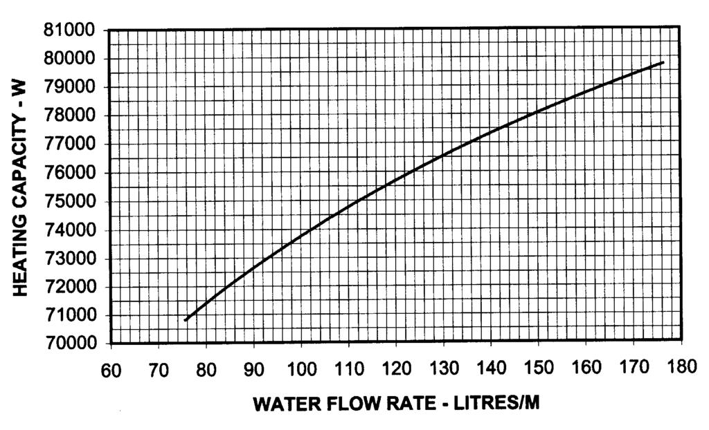
13 Unit Selection Procedure The cooling and heating capacities of the fan coil units can be determined by the Cooling Capacity Performance Chart and Heating Capacity Performance Chart in the following pages based on nominal air flow at standard water temperature. The total and sensible capacities must be adjusted as variables come in. A sample of selection procedure is given as below: Step 1 Determine type of fan coil units to be used, i.e. ceiling cassette (MCK-AW Series); ceiling exposed (MCM-DW Series); etc. Step 2 Select a tentative unit size based on cooling capacities at nominal air flow. Design entering air temperatures and required water flows from cooling capacities chart (Page 14-35) or the nominal capacities ratings (Page 3-10) from standard specification. Step 3 Determine the nominal unit cooling capacities for the unit selected. If the cooling capacities chart must be used, the following information must be known :- a) Design water temperature rise b) Design entering water temperature c) Design entering air dry bulb temperature d) Design entering air wet bulb temperature Example of how to read the cooling performance chart. MCK050AW Total Cooling Capacity Sensible Capacity 11
14 Step 4 If air flow value is different from the nominal value(high speed), then refer to specification from Page 3 to 10 for the air flow required(medium or low speed). Determine the total and sensible correction factor from Air Flow Capacity Correction Factor (Page 57). Step 5 If the unit is to operate at an altitude above sea level, multiply the capacity correction factors by an Altitude Correction Factors. Refer to Page 57. Step 6 Calculate the actual cooling capacity by multiply the nominal capacity (from Step 3) with Air Flow Capacity Correction Factor from Step 4 and the Altitude Correction Factor from Step 5. Actual Capacity, W = Nominal capacity (Step 3) x Air Flow Capacity Correction Factor (Step 4) x Altitude Correction Factor (Step 5) Step 7 Water flow rate can be determined by: Litres/Min = Total Cooling Capacity, W 70 x Water Temperature Rise C USGPM = Total Cooling Capacity, Btu/H 500 x Water Temperature Rise F Step 8 Heating Capacities at nominal air flow (Page 36 to 51 - Heating Performance Chart) are based on standard condition of 60 C EWT and 21 C EAT. The actual heating capacity can be obtained by using the Heating Capacity Correction Factor (Page 57) and Altitude Correction Factor as per Step 5. Hence Actual Heating Capacity, W = Nominal Capacity (Page 36 to 51) x Heating Capacity Correction Factor (Page 57) x Air Flow Capacity Correction Factor (Step 4) x Altitude Correction Factor (Step 5) Step 9 Water Pressure Drop Tables are on Page 52 to 56. EXAMPLE Select a ceiling cassette type fan coil unit at the following design specification: Room design condition : 26.7 C DB / 19 C WB Room Cooling Load : 7 kw sensible capacity / 10 kw total capacity Room Heating Load : 10 kw Entering water temperature : 7 C cooling / 54 C heating Water temperature rise : 5 C Air Volume : 1700 cmh Altitude : 600 m SOLUTION Step 1 Based on the type of fan coil required and the design conditions, tentatively select MCK050AW. From the cooling capacity performance chart (Page 15), at 26.7 C DB / 19 C WB air temperature, 7 C entering water temperature and with 5 C water temperature rise, the cooling capacity for this unit is 11 kw total capacity and 7.6 kw sensible 12
15 Step 2 From page 57, the air flow correction factor table, at high speed, the air volume is 1840 cmh and medium speed is 1680 cmh, hence high speed is selected. And the correction factor is hence 1.0. If lower air flow required, then use the medium and low fan speed. The correction factor can be determined by getting the ratio of air flow (i.e. medium or low speed / high speed). Step 3 As the unit is operating at 600m above sea level, the Altitude correction factor is 0.98 total and 0.93 sensible. Step 4 Multiply the cooling capacities obtained from step 1 (as per specification and design condition) by correction factors from (2) and (3) Actual total cooling capacity = 11 x 1.0 x 0.98 kw = kw Actual sensible cooling capacity = 7.6 x 1.0 x 0.93 kw = kw Step 5 Water flow rate = Litres/M = W = x 5 Step 6 From Heating Capacity Performance Chart (Page 40), determine the heating capacity at the nominal air MCK050AW volume by using the flow rate calculated in Step 5. The heating capacity is at kw. Step 7 From Heating Capacity Correction Factor Tables at 54.4 C water entering temperature and 26.7 C entering air temperature, the correction factor is 0.717, Actual Heating Capacity = x 0.98 x = kw Step 8 Water Pressure Drop can be estimated from water Pressure Drop Table (Page 52 to 56) using interpolate method: At flow rate of 30.8 Litres/Min, the nominal pressure drop is 68,322 Pa Pressure drop correction factor = x (EWT C x ) = Hence the actual pressure drop = nominal pressure drop x correction factor = 69,921 Pa. 13
16 Cooling Capacity Performance Chart MWM005FW 14
17 MWM007FW 15

18 MWM010FW 16

19 MWM015FW 17

20 MWM020FW 18

21 MWM025FW 19

22 MCK020AW 20

23 MCK025AW 21

24 MCK030AW 22

25 MCK040AW 23

26 MCK050AW 24

27 MCK015BW 25

28 MCK015BWN 26

29 MCK020BW 27

30 MCK025BW 28

31 MCK030BW 29

32 MCM020DW 30

33 MCM025DW 31

34 MCM030DW 32

35 MCM040DW 33

36 MCM050DW 34

37 MCC010CW 35

38 MCC015CW 36

39 MCC020CW 37

40 MCC025CW 38

41 MCC030CW 39

42 MCC040CW 40

43 MCC050CW 41

44 MCC060CW 42
45 MCC028CW 43

46 MCC038CW 44

47 MDB075BW 45

48 MDB100BW 46

49 MDB125BW 47

50 MDB150BW 48
51 Heating Capacity Performance Chart Wall Mounted Type MWM010FW AWM10FW HEATING CAPACITY - W WATER FLOWRATE - LITRE/MIN MWM015FW AWM15FW HEATING CAPACITY- W WATER FLOWRATE - LITRE/MIN 49
52 MWM020FW AWM20FW HEATING CAPACITY - W WATER FLOWRATE - LITRE/MIN MWM025FW AWM25FW HEATING CAPACITY- W WATER FLOWRATE - LITRE/MIN 50
53 Ceiling Cassette Type MCK020AW MCK025AW 51
54 MCK030AW MCK040AW 52
55 MCK050AW 53
56 MCK015BW HEATING CAPACITY - W WATER FLOWRATE - LITRE/MIN MCK020BW HEATING CAPACITY- W WATER FLOWRATE - LITRE/MIN 54
57 MCK025BW HEATING CAPACITY - W WATER FLOWRATE - LITRE/MIN MCK030BW HEATING CAPACITY- W WATER FLOWRATE - LITRE/MIN 55
58 Ceiling Suspended Type MCM020DW MCM025DW 56
59 MCM030DW MCM040DW 57

60 MCM050DW 58

61 Ceiling Concealed Type MCC010CW MCC015CW 59
62 MCC020CW MCC025CW 60

63 MCC030CW MCC040CW 61
64 MCC028CW HEATING CAPACITY - W WATER FLOW RATE - LITRES/M MCC038CW HEATING CAPACITY - W WATER FLOW RATE - LITRES/M 62

65 MCC050CW MCC060CW 63


66 Ducted Blower Split Type MDB075BW MDB100BW 64

67 MDB125BW MDB150BW 65
68 Water Flow Rate Vs Pressure Drop MODELS MWM010FW MWM015FW MWM020FW MWM025FW FLOW RATE WATER PRESSURE DROP LITRES / M USGPM Pa PSI Note : a. PRESSURE DROP CORRECTION FACTOR = * ( EWT C * ) b. PRESSURE DROP CORRECTION FACTOR = * EWT F 66
69 MODELS MCK020AW MCK025AW MCK030AW MCK040AW MCK050AW FLOW RATE WATER PRESSURE DROP LITRES / M USGPM Pa PSI , , , , , , , , , , , , , , , , , , , , , , , , , MODELS FLOW RATE WATER PRESSURE DROP LITRES / M USGPM Pa PSI MCK015BW MCK020BW MCK025BW MCK030BW Note : a. PRESSURE DROP CORRECTION FACTOR = * ( EWT C * ) b. PRESSURE DROP CORRECTION FACTOR = * EWT F 67
70 MODELS MCM020DW MCM025DW MCM030DW MCM040DW MCM050DW FLOW RATE WATER PRESSURE DROP LITRES / M USGPM Pa PSI , , , , , , , , , , , , , , , , , , , , , , , , , , Note : a. PRESSURE DROP CORRECTION FACTOR = * ( EWT C * ) b. PRESSURE DROP CORRECTION FACTOR = * EWT F 68
71 MODELS MCC010CW MCC015CW MCC020CW MCC025CW MCC028CW MCC030CW MCC038CW MCC040CW MCC050CW MCC060CW FLOW RATE WATER PRESSURE DROP LITRES / M USGPM Pa PSI , , , , , , , , , , , , , , , , , , , , , , , , , , , , , , , , , , , , , , , , , , Note : a. PRESSURE DROP CORRECTION FACTOR = * ( EWT C * ) b. PRESSURE DROP CORRECTION FACTOR = * EWT F 69
72 MODELS MDB075BW MDB100BW MDB125BW MDB150BW FLOW RATE WATER PRESSURE DROP LITRES / M USGPM Pa PSI , , , , , , , , , , , , , , , , , , , , Note : a. PRESSURE DROP CORRECTION FACTOR = * ( EWT C * ) b. PRESSURE DROP CORRECTION FACTOR = * EWT F 70
73 Correction Factors ALTITUDE CORRECTION FACTORS Elevation, m Total Capacity Sensible Capacity HEATING CAPACITY CORRECTION FACTORS EAT ENTERING TEMPERATURE, C C Notes : Adjusted capacity, W (@ Nominal air flow) = base heating capacity (@ nominal 60 C EWT, 21.1 C EAT) x Heating Capacity Correction Factor 71
74 Wiring Diagrams Model : MWM005/007/010/015FW (G6 Controller) Model : MWM005/007/010/015FW (SLM-3) 72
75 Model : MWM005/007/010/015FW (Netware 2) Model : MWM005/007/010/015FWN (G6 Controller) 73
76 Model : MWM005/007/010/015FWN (SLM-3) Model : MWM005/007/010/015FWN (Netware 2) 74
77 Model : MWM020/025FW (G6 Controller) Model : MWM020/025FW (SLM-3) 75
78 Model : MWM020/025FW (Netware 2) Model : MWM020/025FWN (G6 Controller) 76
79 Model : MWM020/025FWN (SLM-3) Model : MWM020/025FWN (Netware 2) 77
80 Model : MCK020/025/030/040/050AW C/W G6 Controller Or Netware-1 CW Wired Controller Model : MCK020/025/030/040/050AWN (With W1V3 Controller Without Valve) 78
81 Model : MCK015/020/025/030BW Model : MCK015/020/025/030BWN (W1V3 Valveless) 79
82 Model : MCM020/025/030/040/050DW (G6 CONTROLLER) Model : MCM020/025/030/040/050DW (NETWARE 2) 80
83 Model : MCM020/025/030/040/050DWN Model : MCC010/015/020/025CW (Netware 2 / SLM-3) 81
84 Model : MCC010/015/020/025CWN Model : MCC028/030/038/040/050/060CW 82
85 Model : MCC028/030/038/040/050/060CWN 83
86 Model : MDB075/100BW - WITHOUT CONTROLLER Model : MDB125/150BW - WITHOUT CONTROLLER 84
87 Controllers TYPE OF CONTROLLER VS TYPE OF FAN COIL MODELS STANDARD CONTROLLER OPTIONAL CONTROLLER MCK020~050AW G6 WIRELESS CONTROL NETWARE 2 CW (WIRED CONTROLLER) MCM020~050DW G6 WIRELESS CONTROL NETWARE 2 CW (WIRED CONTROLLER) MCC010~060CW NETWARE 2 CW (WIRED CONTROLLER) MDB075~150BW WITHOUT CONTROLLER - SELF DIAGNOSIS TABLE Wireless Wired Operation / Faulty Indication Power LED Other LEDs 7 Segment Display Blinks 4 times Fan blinks E1 Blinking Room sensor contact loose / short Blinks 4 times Sleep blinks E2 Blinking Indoor coil sensor contact loose / short Blinks 1 time Cool blinks E4 Blinking Pipe water temperature fault Blinks 2 times Cool & Fan blinks E6 Blinking Pump faulty OPERATION GUIDE FOR G FAN SPEED AND VENTILATION MODE SELECTION Press the button until the desired fan speed is achieved. OPERATION MODES Press the mode button for select the type of operating mode. Cooling only unit: Cool Dry Fan. Heating cycles: Cool Dry Heat Fan. TIMER SETTING Press set button to activate the timer setting (from 1 hour to 15 hour) of the air conditioning unit. It will be in "On" or "Off" condition after the set time depending to the current condition (either from "On" to Off" or vise versa) To cancel the timer setting, press the button continuously until the timer display goes off. 4 8 SIGNAL TRANSMISSION INDICATION Blink to confirm the last setting has been send to the unit. SLEEP MODE Press the button to activate sleep mode. This mode can only be activated while in cooling or heating mode operation. If it is activated in COOL mode, the set temperature will be increase 0.5 C after 30 minutes, 1 C after 1 hour and 2 C after 2 hours TEMPERATURE SETTING Set the desire room temperature. Press button to increase or decrease the set temperature. Setting range are between 16 C to 30 C setting (60 F to 80 F)(Optional setting from 20 C to 30 C). Press or button simultaneously will toggle the temperature setting between C and F. ON / OFF switch Press to start the air conditioner unit. Press again to stop the unit. AUTOMATIC AIR SWING Press the button to activate the automatic air swing function. The swing angle ranging from horizontal to 25 to bottom. 85
88 Netware 2 D A B C E F G I H J Display A : Fan Speed Display Displays the fan speed setting (Auto/High/Medium/Low) B : Operation Mode Display Displays the current mode of operation. C : Sleep Display Display the sleep / energy saving status. D : Error Display E : Swing Display Display the aur swing status. F : Key Lock Display Display indicates when key lock function is activated. G : C or F Display Display the temperature in C or F. H : Current Time Start / Stop Time Display Display the current time as well as the start and stop time programmed. I : On / Off Status Lamp Display J : Set Temperature or Room Temperature Display Display the set or room temperature. Other functions Last state memory using battery back up. For 7-days programmable time option, battery back up is used to retain the last state data. Units without battery back up will depend on the EEPROM on the main board. Error Indicator Error code will be shown for any abnormal condition detected. Refer to main board error codes for detail. 86
89 O K L P M Q N Operation K : Operating Lamp L : On / Off Starting operation : When the unit is off, press the ON/OFF button. The operation LED lights and the unit will be turned on. Stopping operation : When the unit is on, press the ON/OFF button. The operation LED is extinguished and controls are turned off. M : Set Temperature Press this button to set the temperature. By pressing up or down once, temperature changes by 1 C (or 1 F). The temperature range is16 C to 30 C (60 F to 85 F). In FAN mode, temperature can not be set. Pressing up and down buttons simultaneously will toggle the temperature unit between C and F. When set temperature button is pressed, the set temperature will be displayed for 5 seconds. After that, room temperature will be displayed. N : Mode Press MODE button to select operation mode from Cool, Heat, Auto, Dry and Fan. The display will show the selected mode. O : Fan Press FAN button to select Auto, High, Medium or Low fan speed. P : Swing Press SWING button to activate the air sweep function. Q : Sleep Press SLEEP button to activate the sleep or energy saving mode. 87
90 S T R X Z U V Y W R : Timer Hold / Resume Display S : Current Time Display T : Operating Lamp U : Key Lock This feature protects the controls from being tampered with by children or unauthorized persons. To activate, press the MINUTE button three times consecutively. KEY LOCK symbol will appear on the LCD display. During this time, ON/OFF button and FAN button can be used. To cancel this feature, press the MINUTE button again three times consecutively. V : Minute When the control is in set clock or set timer mode, pressing the HOUR button will change the set hour. W : Hour When the control is in set clock or set timer mode, pressing the HOUR button will change the set hour. X : Day When the control is in set clock or set timer mode, pressing the DAY button will change the set day. Y : Clock Press button once to set the clock mode. Press button again to disable the clock mode. When the clock mode is activated, the time and date can be set or changed by pressing the DAY, HOUR or MINUTE buttons. Z : Timer Hold / Resume If 7-days timer is set, the word TIMER ACTIVE is displayed. To clear the timer setting, press and hold the HOLD button for 2 to 3 seconds until the word TIMER ACTIVE is no longer displayed. To resume the timer setting after the timer has been placed on hold, press and hold the HOLD button again for 2 to 3 seconds until the word TIMER ACTIVE is displayed. 88
91 SLM 3 WIRED CONTROLLER SENSOR ON/OFF 1 FAN ON/OFF 2 5 TEMP TIMER AUTO HIGH MED LOW FAN SWING COOL DRY HEAT FAN MODE SLEEP TEMP SWING SLEEP TIMER MODE 7 SLM AC5300 (OPTIONAL) 1. ON/OFF switch Press to start the air conditioner unit. Press again to stop the unit. 2. Temperature setting Set the desired room temperature. Press button to increase or decrease the set temperature. Setting range are between 16 o C to 30 o C (60 o F to 80 o F). 3. Operation Modes Press the mode button for select the type of operating mode. - Cooling Only : COOL, DRY, FAN - Heat Pump : AUTO, COOL, DRY, HEAT, FAN (AUTO mode is represented by both COOL and HEAT LED light on) 4. Fan Speed selection. Press the button until the desired fan speed is achieved. 5. Timer. Press the set button to select the switch timer of the air conditioner unit (the setting range is between 1 to 10 hours). 6. Sleep mode Press button to activate the sleep function. This function can only be activated under cool or heating mode operation. When it is activated under cool mode operation, the set temperature will increase 0.5 o C after 30 minutes, 1 o C after 1 hour and 2 o C after 2 hours. If it is activated under HEAT mode operation, the set temperature will be decreased 0.5 C after 30 minutes, 1 C after 1 hour and 2 C after 2 hours. 7. Air Swing Press button to activate the automatic air swing function. 8. Sensor Infra red sensor to receive signals from wireless controller. 9. LED display To display the set temperature (in º C) and timer delay setting (in hours). 10. Transmission source To transmit signals to the air conditioner. 89
 Fix the bottom case onto the wall with the 2 wooden screws provided.")
92 Installation Of LCD Remote Controller Step-By-Step Guide i) First, open up the casing of the LCD remote controller into its top and bottom case using a screwdriver. To do this, insert the screwdriver into the lower slot and slide it in the outward direction. ii) Fix the bottom case onto the wall with the 2 wooden screws provided. Then, insert the 4 connecting wires (from the main board) through the slot on the lower center of the case as shown below. iii) Connect one end in each of the 3 wires to the terminal block behind the top case as illustrated. iv) To select cooling only model or heatpump model, some adjustment required in the dip switch setting. v) Fasten back the top and bottom case into place. Hook the two upper claws into their respective slots and snap the lower part shut. Dip switch setting for model selection Pin Function Remarks JH & JD RESERVE JH-OFF, JD-OFF COOL, DRY, FAN JH-OFF, JD-ON COOL, DRY, FAN, HEAT JH-ON, JD-OFF COOL, DRY, FAN HEAT, AUTO JH-ON, JD-ON RTC NO REAL TIME CLOCK RTC-OFF REAL TIME CLOCK RTC-ON NO DRY WITHOUT DRY FUNCTION NO DRY-ON DRY FUNCTION NO DRY-OFF 90
93 Blower Performance Curves BLOWER PERFORMANCE CURVE MCC 010CW 91
94 BLOWER PERFORMANCE CURVE MCC 015CW 92
95 BLOWER PERFORMANCE CURVE MCC 020CW 93
96 BLOWER PERFORMANCE CURVE MCC 025CW 94
97 BLOWER PERFORMANCE CURVE MCC 028CW 95
98 BLOWER PERFORMANCE CURVE MCC 030CW 96
99 BLOWER PERFORMANCE CURVE MCC 038CW 97
100 BLOWER PERFORMANCE CURVE MCC 040CW 98
101 BLOWER PERFORMANCE CURVE MCC 050CW 99
102 BLOWER PERFORMANCE CURVE MCC 060CW 100
103 Model : MDB075BW (Double Blowers) Model : MDB100BW (Double Blowers) 101
104 Model : MDB125/150BW 102


105 Outlines And Dimensions Indoor Unit Model: MWM 010F W / 015FW Note : Dimension in mm Indoor Unit Model : MWM 020FW / 025FW Note : Dimension in mm 103
106 Model : MCK020/025/030/040/050AW MCK015/020/025/030BW B C D E F H A J I G K MODEL A B C D E F G H I J K MCK-AW MCK-BW
107 Model : MCM 020/025DW Model : MCM 030/040/050DW Model A B C D E F G H I J K L M MCM030DW MCM040DW MCM050DW
108 Model : MCC010CW Model : MCC015/020/025CW Model A B C D E F G H I J K L M N O P MCC015CW MCC020CW MCC025CW
109 Model : MCC 028CW Model : MCC 038CW 107
110 Model : MCC030CW Model : MCC040CW 108
111 Model : MCC050CW Model : MCC060CW 109
112 Model : MDB075/100BW Model A B MDB075BW MDB100BW Model : MDB125BW 110
113 Model : MDB150BW 111
114 General Installation Guide Preliminary Site Survey Electrical supply and installation is to conform to LOCAL AUTHORITY's (e.g. National Electricity Board) CODES and REGULATIONS. Voltage supply fluctuation must not exceed ± 10% of rated voltage. Electricity supply lines must be independent of welding transformers which can cause supply fluctuation. Ensure that the location is convenient for wiring and piping. Mounting For ceiling mounted models, locate a position where piping and ducting work can be kept to a minimum. Ensure that overhead supports are strong enough to hold the unit's weight. Position hanger rods and check for alignment with the unit. Check that hangers are secure and that the base of fan coil unit is level in two horizontal positions. Piping Drain and water piping must be accurately connected. Please refer to "Specification Sheet" for piping sizes. Piping Support All water mains must be adequately supported to carry the necessary weight involved, provisions must be made by the installing contractor to allow for adequate free movement of all vertical and horizontal risers and run outs. Due to the fact that cold water will be circulated through the water mains, a sizeable movement of the water mains can be expected due to contraction. If for example, the piping is rigidly supported with no provision for movement, it is very possible that the tubing of fitting may be broken causing water leakage in the conditioned spaces throughout the building. Coil Venting Each standard basic unit coil is equipped with a manually operated air vent which is installed at the end of a small copper line leading into the highest point of the coil. By means of this valve, air may be vented manually, from the coil to keep it operating at full capacity. When water is first introduced into a coil, air is sometimes trapped in the coil tubing. This trapped air will reduce cooling capacity and create "Bubbling" or "Clanking" noise within the units. To release air trapped in the coil, press the air vent head to allow air to flow out of the air vent opening. Release when a steady stream of water appear. Electrical Connection As wiring regulations differ from country to country, please refer to your LOCAL ELECTRICAL CODES for field wiring regulations and ensure that they are complied with. Besides, take note of the following general precaution: 1) Ensure that the rated voltage of the unit corresponds to the name plate before commencing wiring work. 2) Provide a power outlet to be used exclusively for each unit and a power supply disconnect and a circuitbreaker for over-current protection should be provided in the exclusive line. 3) The unit must be EARTH to prevent possible hazards due to insulation failure. 4) All wiring must be firmly connected. 112
115 General Operation Guide Start-Up The following procedure must be completed before any attempts is made to put the entire system Into operation: 1) Piping connections completed. 2) Electrical connections completed. 3) Duct connections completed. 4) Auxiliary drain pans in position where required. 5) Drain line draining into drain pans. 6) Filters correctly installed and free of construction debris. 7) Motor-blower assembly rotates freely. 8) Unit Hydrostatically tested and air vented. Starting The Fan Coil Unit 1) Turn on the switch of water pump. 2) Start water chiller. 3) Operate the fan coil unit by turning on the fan and set the control switch to get the desired speed. 4) Inspect the duct and piping condition and rectify problem (e.g. vibration, noise, etc.) if exist. Servicing And Maintenance Fan coil units are designed to operate continuosly with minor routine maintenance. Since fan coil units cool the discharging forced air, the efficiency with which the units operate is directly related to the amount of air passing through the coil. Air Filters The function of the air filters is to remove foreign matter such as dirt, soot, pollen and certain other impurities from the air passing through it. A clogged or dirty filter not only fails to do the job for which it is designed, but restricts the flow of air over the coil. The importance of cleaning the filter before it becomes clogged must be greatly stressed. The frequency with which a filter should be cleaned will depend upon the amount of dust and foreign material that enters a unit, and this depends upon location and situation. The washable viledon or saranet filter may be cleaned by tapping the filter on a solid surface to dislodge heavy particles. Wash under stream of warm water, with detergent if necessary. Dry it thoroughly before replacing. Fan Motor The fan motor is prelubricated and sealed at the factory. Therefore, no lubricating maintenance is required. Coils Clean coil unit by brushing between fins with a nylon brush. Brushing should be followed by cleaning with a vacuum cleaner. The coil may also be cleaned by using a high pressure air hose and nozzle if a compressed air source is available. It should be pointed out that if suitable air filter is used and taken care of properly, the coils need no cleaning. Drain Pipe The drain pipe should be checked before operation of unit is begun. If it is clogged, steps should be taken to clean the debris so that condensate will flow out easily. Replacement Of Parts Replacement of parts are available through your local dealers. When ordering parts, you must supply 1) Model name of the unit. 2) Serial number of the unit. 3) Part name and number. 113
 46 92 33 33 - Télex: 790 536 F - Télecopie: (33) 46 91 38")
116 DOP : Americas Industrial Park Boulevard, P.O. Box 1551, Minneapolis, MINI USA (612) Asia - Jalan Pengapit 15/19, P.O. Box 7072, Shah Alam, Selangor Darul Eshan, Malaysia - Tel: Fax: Telex: MA Europe - 42 Cours Jean Jaurès Pons - France - Tél: (33) Télex: F - Télecopie: (33)
Wall Mounted Split Systems
 MWM - 2005 Wall Mounted Split Systems Models: MWM 007F/FR MWM 010F/FR MWM 015F/FR MWM 020F/FR MWM 025F/FR MWM 030F/FR Contents Features... 1 Nomenclature... 2 Specifications... 3 Performance Table... 11
Your Climate. We're There. TM: MDB B 2140B. Ducted Split Systems. Models: MDB 075B - MDB750B MDB 075B/B - MDB500BR. Air Conditioning REGISTERED
 Your Climate. We're There. TM: MDB B 2140B Ducted Split Systems Models: MDB 075B - MDB750B MDB 075B/B - MDB500BR REGISTERED Air Conditioning Contents Nomenclature System... 2 Features... 2 General Specifications...3-5
Models: ACC 75D/DR ACC 100D/DR. ACC - D (Draft) Ceiling Concealed Split Systems
 Ceiling Concealed Split Systems") Models: ACC 75D/DR ACC 100D/DR ACC - D2-2007 (Draft) Ceiling Concealed Split Systems CONTENTS 1. NOMENECLATURE... 2 2. FEATURES... 4 3. PRODUCT LINE UP... 5 4. SPECIFICATIONS... 8 5. OPERATING RANGE...
Models: ACC 75D/DR ACC 100D/DR ACC - D2-2007 (Draft) Ceiling Concealed Split Systems CONTENTS 1. NOMENECLATURE... 2 2. FEATURES... 4 3. PRODUCT LINE UP... 5 4. SPECIFICATIONS... 8 5. OPERATING RANGE...
Ceiling Mounted Cassette Unit
 Brochure AP-MCK-13 Ceiling Mounted Cassette Unit Products manufactured in an ISO certified facility. This document contains the most current product information as of this printing. For the most up-to-date
McQuay HydroflexTM Residential and Light Commercial Chilled Water System
 Advanced, affordable chilled water solutions. McQuay HydroflexTM Residential and Light Commercial Chilled Water System McQuay Hydroflex System Chilled Water Solutions Made Affordable Benefits: Advanced
All side discharge units are having high pressure switch (LP switch- Optional) and time delay relay. Compressors are scroll type, Copeland make.
 and time delay relay. Compressors are scroll type, Copeland make.") All outdoor units are designed to perform satisfactorily at 52 C, with the option of either top discharge condensing units, with Copeland reciprocating scroll compressors. All top discharge condensing
All outdoor units are designed to perform satisfactorily at 52 C, with the option of either top discharge condensing units, with Copeland reciprocating scroll compressors. All top discharge condensing
MODEL: ACWD CEILING CONCEALED Chilled Water Fan Coils Unit
 MODEL: ACW200D ACW300D ACW400D ACW500D ACW600D ACW800D ACW900D ACW1000D ACW1200D ACW1400D ACWD-2006 ACWD_2006_Cover.indd 1 CEILING CONCEALED Chilled Water Fan Coils Unit 2006-5-25 17:24:07 Contents Main
EHH SERIES DRAW THROUGH FAN COILS CFM
 EHH SERIES DRAW THROUGH FAN COILS 400-5000 CFM TABLE OF CONTENTS TABLE OF CONTENTS 2 INTRODUCTION 3 GUIDE SPECIFICATIONS 4 UNIT OVERVIEW 6 TECHNICAL DATA 8 DIMENSIONS 10 COMPUTER SELECTION 11 GEMCOOL PROFILE
C&H NORDIC Commercial 4 SERVICE MANUAL
 C&H NORDIC Commercial 4 SERVICE MANUAL CONTENTS PRODUCT...3 1 MODELS LIST... 3 1.1 Outdoor Unit.... 3 1.2 Indoor Unit.... 4 2 PRODUCT DATA.... 5 2.1 Product Data of Indoor Unit... 5 2.2 Operation Range...
Fan Coil Unit. Product Catalogue. Chilled Water PRODUCT SYSTEM PCXF14. Wall Mounted. Ceiling Cassette. Ceiling Convertible. Ducted
 PCXF14 Chilled ater PRODUCT SYSTEM all Mounted Ceiling Cassette Ceiling Convertible Fan Coil Unit Ducted Product Catalogue Products manufactured in an ISO certified facility. This document contains the
PLXRMM1606B. Wall Mounted. FTN-A Series. COOLING ONLY [50Hz] V
![PLXRMM1606B. Wall Mounted. FTN-A Series. COOLING ONLY [50Hz] V](/thumbs/96/128248655.jpg "PLXRMM1606B. Wall Mounted. FTN-A Series. COOLING ONLY [50Hz] V") PLXRMM1606B Wall Mounted FTN-A Series COOLING ONLY [50Hz] 220-240V ELEGANT, EFFICIENT 1 Daikin s FTN-A series wall mounted air conditioner that not only saves energy but also ozone friendly. Stylish Flat
PLXRMM1606B Wall Mounted FTN-A Series COOLING ONLY [50Hz] 220-240V ELEGANT, EFFICIENT 1 Daikin s FTN-A series wall mounted air conditioner that not only saves energy but also ozone friendly. Stylish Flat
Floor Standing. FV Series PLXSPH1502. COOLING ONLY [60Hz]
![Floor Standing. FV Series PLXSPH1502. COOLING ONLY [60Hz]](/thumbs/78/78280692.jpg "Floor Standing. FV Series PLXSPH1502. COOLING ONLY [60Hz]") PLXSPH1502 Floor Standing FV Series Dealer Lot 60334, Persiaran Bukit Rahman Putra 3, Taman Perindustrian Bukit Rahman Putra, 47000 Sungai Buloh, Selangor Darul Ehsan, Malaysia http://www.daikin.com/global_ac/
PLXSPH1502 Floor Standing FV Series Dealer Lot 60334, Persiaran Bukit Rahman Putra 3, Taman Perindustrian Bukit Rahman Putra, 47000 Sungai Buloh, Selangor Darul Ehsan, Malaysia http://www.daikin.com/global_ac/
High Wall Split Systems Cool Only 9K - 12K - 18K - 24K. Auto. Auto. Fan Speed. Smart LCD Wireless Control. Auto Mode.
 HFC4 1 0 A 0-40V ~, 0Hz 1Ph High Wall Split Systems Cool Only 9K - 1K - 18K - 4K R-410A IAQ $ Auto Auto Fan Speed Timer s Easy Flexible Installation Smart LCD Wireless Control Auto Mode Auto Restart Easy
V ~, 50Hz 1Ph. High Wall Split Systems Heat Pump 9K - 12K - 18K - 24K - 28K. Auto. Auto Fan Speed. Auto. Smart LCD Wireless Control.
 HFC4 1 0 A 0-40V ~, 0Hz 1Ph High Wall Split Systems Heat Pump 9K - 1K - 18K - 4K - 8K R-410A Compressor Super Quiet AMS Anti-dust Filters Auto Fan Speed Timer Functions Defrost Protection Smart LCD Wireless
MHWW-24-H-1 Chilled/Hot Water Hi-Wall Fan Coil 2-Pipe Heat / Cool Fan Coil 24,000 BTUH
 MHWW-24-H-1 Chilled/Hot Water Hi-Wall Fan Coil 2-Pipe Heat / Cool Fan Coil 24,000 BTUH MHWW NOMENCLATURE BREAKDOWN 2-Pipe Heat/Cool Hi-Wall Fan Coil MHWW- 24 - H -1 2-Pipe Heat/Cool Heat/Cool Voltage 1=
MHWW-09-H-1 Chilled/Hot Water Hi-Wall Fan Coil 2-Pipe Heat / Cool Fan Coil 9,000 BTUH
 MHWW-09-H-1 Chilled/Hot Water Hi-Wall Fan Coil 2-Pipe Heat / Cool Fan Coil 9,000 BTUH MHWW NOMENCLATURE BREAKDOWN 2-Pipe Heat/Cool Hi-Wall Fan Coil MHWW- 09 - H -1 2-Pipe Heat/Cool Heat/Cool Voltage 1=
Fan Coil Unit. Product Catalogue. Chilled Water PRODUCT SYSTEM PCXF14. Wall Mounted. Ceiling Cassette. Ceiling Convertible. Ducted
 PCXF14 Chilled ater PRODUCT SYSTEM all Mounted Ceiling Cassette Ceiling Convertible Fan Coil Unit Ducted Product Catalogue Products manufactured in an ISO certified facility. This document contains the
Inverter Wall Mounted Series
 PCXRY14 Inverter Wall Mounted Series R410A Products manufactured in an ISO certified facility. This document contains the most current product information as of this printing. 2014-09 Printed In Malaysia
High Ambient / High Efficiency Series. R - 410a. 50Hz. Ducted Split Air Conditioners (5.0 kw kw)
") High Ambient / High Efficiency Series R - 410a 50Hz Ducted Split Air Conditioners (5.0 kw - 17.5 kw) ISO 9001 : 2008 ISO 14001 : 2004 ISO 18001 : 2007 R - 410a 50Hz Introduction: Established in the year
High Ambient / High Efficiency Series R - 410a 50Hz Ducted Split Air Conditioners (5.0 kw - 17.5 kw) ISO 9001 : 2008 ISO 14001 : 2004 ISO 18001 : 2007 R - 410a 50Hz Introduction: Established in the year
PCXSPH1732A. Warning. Head office: Umeda Center Bldg., , Nakazaki-Nishi, Kita-ku, Osaka, Japan.
 Warning Daikin products are manufactured for export to numerous countries throughout the world. Prior to purchase, please confirm with your local authorised importer, distributor and/or retailer whether
Compact, Self-Contained unit that offer low installation cost plus dependable performance.
 0 Compact, Self-Contained unit that offer low installation cost plus dependable performance. From carrier s excellence in engineering come a new, compact of single package horizontal and vertical water
LOW STATIC HYDRONIC DUCTED UNIT
 LOW STATIC HYDRONIC DUCTED UNIT PDWA-~AC SERIES PDWA(4R)-~-V-MEDC PDWA(4R)-~-V-MEEU PDWA(R)-~-V PDWA(R+1)-~-P Model cooling capacity( KW) at Medium Speed cooling capacity (KW) at Medium Speed cooling capacity
Product Specifications. Vertical Floor Consoles By First Co.
 NOW WITH 18 GAUGE CABINET AND FACTORY INSTALLED SERVICE SWITCH Product Specifications VFB Series VSB Series VCB Series Vertical Console Fan Coils 300-00 CFM Vertical Floor Consoles By First Co. VFB Series
technical data Fan coil unit FWB small duct unit
 technical data Fan coil unit FWB small duct unit TABLE OF CONTENTS FWB 1. Nomenclature ---------------------------------------------------------------------- 2 2. Features -----------------------------------------------------------------------------
Split Type Air Conditioners FTNE-M Series Cooling Only [50 Hz]
![Split Type Air Conditioners FTNE-M Series Cooling Only [50 Hz]](/thumbs/87/95046843.jpg "Split Type Air Conditioners FTNE-M Series Cooling Only [50 Hz]") PCRHK1543 Warning Ask a qualified installer or contractor to install this product. Do not try to install the product yourself. Improper installation can result in water or refrigerant leakage, electrical
PCRHK1543 Warning Ask a qualified installer or contractor to install this product. Do not try to install the product yourself. Improper installation can result in water or refrigerant leakage, electrical
Horizontal Water Source Heat Pumps And Cooling Only Unit
 MWH-B-2005 Horizontal Water Source Heat Pumps And Cooling Only Unit Models: MWH MWH MWH MWH MWH 011 B/BR MWH 012 B/BR MWH 015 B/BR MWH 020 B/BR MWH 025 B/BR MWH 030 B/BR 040 B/BR 050 B/BR 060 B/BR 070
Ceiling Mounted Cassette Unit
 CEILING CASSETTE A5CK-E SERIES - R410A COOLING ONLY A5CK20E A5CK25E A5CK28E A5CK40E A5CK40E A5CK40E A5CK40E A5CK50E A5LC20C A5LC25C A5LC28C A5LC35D A5LC35D A5LC40D A5LC40D A5LC50D Btu/hr 18300 22200 27000
DC INVERTER MULTI-SYSTEM AIR CONDITIONER
 TECHNICAL & SERVICE MANUAL OUTDOOR UNIT : CU-3KE19NBU CU-4KE24NBU CU-4KE31NBU DC INVERTER MULTI-SYSTEM AIR CONDITIONER Capacity at 0V 19,100 BTU/h,200 BTU/h 30,600 BTU/h Outdoor Model No. CU-3KE19NBU CU-4KE24NBU
DESIGN & TECHNICAL MANUAL
 AIR CONDITIONER Wall mounted type DESIGN & TECHNICAL MANUAL INDOOR ASYG07KGTA ASYG09KGTA ASYG12KGTA ASYG14KGTA OUTDOOR AOYG07KGCA AOYG09KGCA AOYG12KGCA AOYG14KGCA DR_AS049EF_02 2017.10.11 Notices: Product
Air Conditioner CONTENTS
 ORDER NO. MAC0509068C2 Air Conditioner CS-F24DD1E5 CU-B24DBE5 CS-F28DD1E5 CU-B28DBE5 CS-F28DD1E5 CU-B28DBE8 CS-F34DD1E5 CU-B34DBE5 CS-F34DD1E5 CU-B34DBE8 CS-F43DD1E5 CU-B43DBE8 CS-F50DD1E5 CU-B50DBE8 CONTENTS
Highly Efficient,Powerful Heating and Cooling.
 AIR-COOLED ROOFTOP PACKAGED AIR CONDITIONERS Series HEAT PUMP PRHG-8,,,20 Cooling Capacity kw Heating Capacity kw PRHG-8 PRHG- PRHG- PRHG-20 PRHG-8 PRHG- PRHG- PRHG-20 23.8 29.7.3 60.8 23.0 32.0 45.5 61.2
Hi - Wall Split Systems. Super Quiet. Auto. Mode. Wireless Control. Smart Airflow ECO ECO. Function SLEEP. Vertical Auto Swing.
 R407C 220-240V ~, 50Hz Hi - Wall Split Systems Technology Tropical Compressor Super Quiet Auto Mode Auto Restart Easy Flexible Installation IAQ Anti-dust Filters AMS AMS Wireless Control Independent Dehumidification
DESIGN & TECHNICAL MANUAL
 AIR CONDITIONER Wall mounted type DESIGN & TECHNICAL MANUAL INDOOR ASYG18KLCA ASYG24KLCA OUTDOOR AOYG18KLTA AOYG24KLTA DR_AS069EF_01 2018.03.16 Notices: Product specifications and design are subject to
Hi - Wall Split Systems 12K - 18K - 24K
 R22 220-240V ~ 50Hz 1Ph Hi - Wall Split Systems 12K - 18K - 24K Technology Tropical Compressor Super Quiet Auto Auto Fan Speed Auto Restart Function Self diagnostic function Active Carbon Electrostatic
Ceiling Concealed High Volume Chilled Water Fan Coil Unit (50/60Hz)
") Technical Manual Ceiling Concealed High Volume Chilled Water Fan Coil Unit (50/60Hz) Models: MCW1400 MCW1600 Air Flow: 2270-3020m3/h MCW1800 Engineered for flexibility and performance. TM MCW-C/F(High
Technical Manual Ceiling Concealed High Volume Chilled Water Fan Coil Unit (50/60Hz) Models: MCW1400 MCW1600 Air Flow: 2270-3020m3/h MCW1800 Engineered for flexibility and performance. TM MCW-C/F(High
Inverter Wall Mounted
 Warning Daikin products are manufactured for export to numerous countries throughout the world. Prior to purchase, please confirm with your local authorised importer, distributor and/or retailer whether
Engineering Data Book
 40VMC Compact 4-Way Cassette Indoor Unit for Variable Refrigerant Flow (VRF) Systems Engineering Data Book Manufacturer reserves the right to discontinue, or change at any time, specifications or designs
Concealed Ducted Split Series R-407C MBH
 Concealed Ducted Split Series R-407C 4-60 MBH Ducted Split with Hermetic Compressor Tropical 50 Hz For more technical information please visit Table of Contents INTRODUCTION NOMENCLATURE UNIT RATING SUMMARY
PLXSID1605. Warning HEAD OFFICE :
 Warning Daikin products are manufactured for export to numerous countries throughout the world. Prior to purchase, please confirm with your local authorised importer, distributor and/or retailer whether
R407C TECHNICAL MANUAL. Packaged Air Conditioner Rooftop A series. UATP-A and UATYP-A Series. Cooling only & Heatpump [50Hz]
![R407C TECHNICAL MANUAL. Packaged Air Conditioner Rooftop A series. UATP-A and UATYP-A Series. Cooling only & Heatpump [50Hz]](/thumbs/75/71890983.jpg "R407C TECHNICAL MANUAL. Packaged Air Conditioner Rooftop A series. UATP-A and UATYP-A Series. Cooling only & Heatpump [50Hz]") R407C TECHNICAL MANUAL Packaged Air Conditioner Rooftop A series UATP-A and UATYP-A Series Cooling only & Heatpump [50Hz] Table of Contents Table of Contents Nomenclature...1 Product Line-Up...2 Application
R407C TECHNICAL MANUAL Packaged Air Conditioner Rooftop A series UATP-A and UATYP-A Series Cooling only & Heatpump [50Hz] Table of Contents Table of Contents Nomenclature...1 Product Line-Up...2 Application
Fans Air Handling Units Air Distribution Products Fire Safety Air Curtains and Heating Products Water terminals SYSWALL. Wall mounted fan coil units
 Fans Air Handling Units Air Distribution Products Fire Safety Air Curtains and Heating Products Water terminals SYSWALL Wall mounted fan coil units SYSWALL Wall mounted fan coil units With a tangential
Part 1 General Information... 1 Part 2 Indoor Units... 7 Part 3 Outdoor Units Part 4 Installation Part 5 Control...
 MCAC-UTSM-2008-11 Contents Part 1 General Information... 1 Part 2 Indoor Units... 7 Part 3 Outdoor Units... 88 Part 4 Installation... 127 Part 5 Control... 136 The specifications, designs, and information
WORLD LARGEST Air Conditioners Manufacturer PRODUCT CATALOGUE GREE MALAYSIA SDN BHD ( M)
") WORLD LARGEST Air Conditioners Manufacturer PRODUCT CATALOGUE GREE MALAYSIA SDN BHD (3278-M) BORA Series WALL MOUNTED SPLIT UNIT NON-INVERTER Series Concealed display Hidden temperature display on a classy
WORLD LARGEST Air Conditioners Manufacturer PRODUCT CATALOGUE GREE MALAYSIA SDN BHD (3278-M) BORA Series WALL MOUNTED SPLIT UNIT NON-INVERTER Series Concealed display Hidden temperature display on a classy
DESIGN & TECHNICAL MANUAL
 AIR CONDITIONER Wall Mounted type DESIGN & TECHNICAL MANUAL INDOOR ASU9RL2 ASU12RL2 OUTDOOR AOU9RL2 AOU12RL2 1.INDOOR UNIT : ASU9RL2 ASU12RL2 DTR_AS072E_01 2012.11.02 1. INDOOR UNIT CONTENTS 1. FEATURE...
K*ES120 DESCRIPTION TECHNICAL GUIDE SPLIT-SYSTEM EVAPORATOR BLOWERS 10 NOMINAL TONS EER 8.5 ACCESSORIES FIELD INSTALLED TABLE 1: ARI RATINGS*
 TECHNICAL GUIDE SPLIT-SYSTEM EVAPORATOR BLOWERS K*ES120 10 NOMINAL TONS EER 8.5 DESCRIPTION These completely assembled dual circuit evaporator blower units include a well-insulated cabinet, a DX cooling
OWNER S MANUAL. R 410A Ductless Split System Air Conditioner and Heat Pump
 R 410A Ductless Split System Air Conditioner and Heat Pump Models DLC4(A/H) Outdoor Unit, DLF4(A/H) Indoor Unit Sizes 9K, 12K, 18K, 24K, 30K and 36K Please read the operating instructions and safety precautions
MHW Air Handling Unit (50/60Hz)
") Technical Manual MHW Air Handling Unit (50/60Hz) MHW015A MHW025A MHW035A MHW050A MHW020A MHW030A MHW040A Engineered for flexibility and performance. TM MHW - 2011 (50Hz/60Hz) Contents Literature No.: TM-MHW-1101A
Technical Manual MHW Air Handling Unit (50/60Hz) MHW015A MHW025A MHW035A MHW050A MHW020A MHW030A MHW040A Engineered for flexibility and performance. TM MHW - 2011 (50Hz/60Hz) Contents Literature No.: TM-MHW-1101A
USER'S OPERATING INSTRUCTIONS
 SAT-2 Thermostat COOL FAN DRY HEAT AUTO SLEEP SWING AUTO ZONE SUN MON TUE WED THU FRI SAT HEATER ON OFF ERR UNIT USER'S OPERATING INSTRUCTIONS CONTENTS Page Introduction 3 Features Summary 3 Display 4
DESIGN & TECHNICAL MANUAL
 AIR CONDITIONER Wall mounted type DESIGN & TECHNICAL MANUAL For Extra Cold Climate Area INDOOR ASU18RLF ASU24RLF OUTDOOR AOU18RLXFWH AOU24RLXFWH DR_AS014EF_04 2017.03.10 Notices: Product specifications
Models: A5HDC20AR A5HDC25AR. Horizontal Ducted Condensing Unit
 Models: A5HDC20AR A5HDC25AR Horizontal Ducted Condensing Unit A5HDC-2009 A5HDC-2009 Table of Contents Table of Contents Nomenclature...2 Indoor Unit...2 Outdoor Unit...3 Product Line-Up...4 Features...6
Engineering Data Book
 40VMF 4-Way Cassette Indoor Unit for Variable Refrigerant Flow (VRF) Systems Engineering Data Book Manufacturer reserves the right to discontinue, or change at any time, specifications or designs without
Slim Line Ceiling Concealed Ducted Split Systems. Medium Static Pressure. Ducted Split System Heat Pump
 0-40V ~ 0Hz Ph 80-40V ~ 0Hz Ph Slim Line Ceiling Concealed Ducted Split Systems Green Medium Static Pressure Ducted Split System Heat Pump - 8-4 - 0 - - 48-0 DC Inverter Inverter Technology $ Efficient
FAN COILS wall mounted
 SERVICE MANUAL FAN COILS wall mounted SF-51H, SF-68H, SF-85H PRODUCT MODELS LIST Model Name Cooling Capacity (W) Product Code Air Flow (m 3 /h) Power Supply (V,Ph,Hz) Remarks SF-51H 2700 EM55001260 550
SPLIT-SYSTEM EVAPORATOR BLOWERS K2EU060, K4EU090, K3EU120 & K1EU180 5 Thru 15 Nominal Tons DESCRIPTION ACCESSORIES FIELD INSTALLED
 (491) SPLIT-SYSTEM EVAPORATOR BLOWERS K2EU060, K4EU, K3EU & K1EU180 5 Thru 15 Nominal Tons DESCRIPTION These completely assembled units include a well-insulated cabinet, a DX cooling coil with copper tubes
SERVICE MANUAL. Inverter Wall Mounted Single Split. MODELS Cooling Only. Heatpump SM-5WM-Y-NA-B1
 SERVICE MANUAL Inverter Wall Mounted Single Split MODELS Cooling Only FTKB09AXVJU FTKB12AXVJU FTKB18AXVJU FTKB24AXVJU FTKN09AXVJU FTKN12AXVJU FTKN18AXVJU FTKN24AXVJU Heatpump FTXB09AXVJU FTXB12AXVJU FTXB18AXVJU
Inverter Wall Mounted
 PLXRHK1603 Inverter Wall Mounted FTKS-A Series COOLING ONLY What is inverter technology? Inverter system ensures faster cooling with signifi cant energy saving. Moreover, it helps to maintain consistent
DESIGN & TECHNICAL MANUAL
 AIR CONDITIONER Wall Mounted type DESIGN & TECHNICAL MANUAL INDOOR AS G07LLCC AS G09LLCC AS G12LLCC OUTDOOR AO G07LLCC AO G09LLCC AO G12LLCC 1.INDOOR UNIT : AS G07LLCC AS G09LLCC AS G12LLCC DTR_AS087E_02
8 Louver position display. 9 SWING display. 10 Set up temperature display. 11 Remote controller sensor display
 Wired remote controller (RBC-AMTE) Operation manual Parts Name of Remote Controller Display section In the display example, all indicators are displayed for the explanation. In reality only, the selected
YAH SERIES FAN COIL UNITS
 YAH Series Fan Coil Units Johnson Controls YORK YAH ceiling mounted cabinet fan coil units are terminal points of central air-conditioning systems. They are designed for fresh air units or to cool, heat,
THIN PROFILE CENTRIFUGAL FAN COIL UNITS SLIM
 THIN PROFILE CENTRIFUGAL FAN COIL UNITS SLIM 0,7 kw 5,2 kw 1,6 kw 10,2 kw 130 m 3 /h 830 m 3 /h SLIM SLIMxx0 vertical with cabinet bottom vertical Available also with feet SLIMxx8 SLIMxx5 SLIMxx4 SLIMxx9
OWNER S MANUAL DLFCAB / DLFCHB / DLFDAB / DLFDHB High Wall Ductless System Sizes 09 36
 OWNER S MANUAL DLFCAB / DLFCHB / DLFDAB / DLFDHB High Wall Ductless System Sizes 09 36 TABLE OF CONTENTS PAGE SAFETY PRECAUTIONS... 2 GENERAL... 2 INDOOR UNIT PART NAMES... 3 REMOTE CONTROL PART NAMES...
Fan Coil Unit 1. BOSCH Climate Fan Coil Unit
 Fan Coil Unit 1 BOSCH Climate 000 Fan Coil Unit 2 Fan Coil Unit Introduction to Bosch Thermotechnology Bosch Thermotechnik GmbH is a leading supplier of resourceefficient heating products and hot water
Residential and Light Commercial Ductless Systems Catalog
 Residential and Light Commercial Ductless Systems Catalog May 2018 Table of Contents Midea Global 3 Ductless Benefits 5 Single and Multi-Zone Solutions 9 Single Zone Residential 13 Max Series 15 Advantage
Technical Data ISU Series. Underceiling/Console Split System Air Conditioners kw 15 kw
 Underceiling/Console Split System Air Conditioners Technical Data ISU Series Featuring SAT- Controller & Long Life Epoxy Coated Outdoor Coil Nominal Cooling Capacity 13. kw 15 kw NOVEMBER 0 ISU SERIES
DESIGN & TECHNICAL MANUAL
 AIR CONDITIONER Wall mounted type DESIGN & TECHNICAL MANUAL INDOOR ASYG07LMCE ASYG09LMCE ASYG12LMCE ASYG14LMCE OUTDOOR AOYG07LMCE AOYG09LMCE AOYG12LMCE AOYG14LMCE DR_AS037EF_01 2016.12.05 Notices: Product
SABIANA ENVIRONMENTAL COMFORT. Air Conditioning Futura Fan Coil Units ICIM
 Air Conditioning Fan Coil Units ICIM ISO 900 - Cert. n 0545/2 Unit heaters Radiant panels Fan coils Air handling units Flues SABIANA ENVIRONMENTAL COMFORT Sabiana is the fan coil that continues the Sabiana
Air-Cooled Mini Chiller. Models: AMAC 040 A/AR AMAC 050 A/AR AMAC 058 A/AR AMAC 075 B/BR AMAC 100 B/BR AMAC 125 B/BR. Manual No: TMA-AMAC-1161
 Models: AMAC 040 A/AR AMAC 050 A/AR AMAC 058 A/AR AMAC 075 B/BR AMAC 100 B/BR AMAC 125 B/BR Air-Cooled Mini Chiller Manual No: TMA-AMAC-1161 REGISTERED ISO 9002 CONTENTS PAGE 1. NOMENCLATURE SYSTEM...
Models: A5LCY 30 ER A5LCY 40 ER A5LCY 50 ER A5LCY 60 ER A5LCY - II Inverter Y Single Split Series II
 Models: A5LCY 30 ER A5LCY 40 ER A5LCY 50 ER A5LCY 60 ER A5LCY - II - 2010 Inverter Y Single Split Series II Table of Contents A5LCY-II-2010 Table of Contents Nomenclature...1 Indoor Unit...1 Outdoor Unit...2
(Non-Inverter & Inverter) R410A
 R410A") LG Commercial Air Conditioner Sinlge Split Type (Non-Inverter & Inverter) R410A Distributed by LG Electronics www.lg.com http://partner.lge.com Copyright 2015 LG Electronics. All rights reserved. Non-Inverter
LG Commercial Air Conditioner Sinlge Split Type (Non-Inverter & Inverter) R410A Distributed by LG Electronics www.lg.com http://partner.lge.com Copyright 2015 LG Electronics. All rights reserved. Non-Inverter
U-MATCH SERIES DC INVERTER AIR CONDITIONERS SERVICE MANUAL
 U-MATCH SERIES DC INVERTER AIR CONDITIONERS SERVICE MANUAL T1/R410A/50Hz (GC201304 - ) CONTENTS PRODUCT... 2 1 MODELS LIST... 2 1.1 Outdoor Unit...2 1.2 Indoor Unit...3 2 NOMENCLATURE... 4 2.1 Outdoor
SKYPAK II, 3 Ton Series, gives you a
 SKYPAK II 3 ton Heating And Cooling self-contained Package SKYPAK II, 3 Ton Series, gives you a complete air-conditioning and heating system as an all in one package unit. Designed for convenient through-the-wall
Application guide FLATAIR - FLCK/FLHK. Providing indoor climate comfort
 Application guide FLATAIR - FLCK/FLHK Providing indoor climate comfort MSL60E-0701 12-2006 Congratulations you have made a wise choice and we feel sure that it will meet your expectation INDEX CONTENTS
AY-AP09DJ SPLIT TYPE ROOM AIR CONDITIONER OPERATION MANUAL AE-A09DJ AY-AP09DJ OUTDOOR UNIT INDOOR UNIT
 R AY-AP09DJ SPLIT TYPE ROOM AIR CONDITIONER OPERATION MANUAL INDOOR UNIT AY-AP09DJ OUTDOOR UNIT AE-A09DJ ENGLISH Thank you for purchasing a SHARP air conditioner. Please read this manual carefully before
Feel the difference! Uncompromised Comfort Unrivaled Value C US. Mark of Superior Quality SERIES
 Feel the difference! SERIES Uncompromised Comfort Unrivaled Value C US TM Mark of Superior Quality Ductless Mini-Split Experience the true individual comfort. Ductless mini-split systems are perfect solution
Technical Guide DESCRIPTION ACCESSORIES FIELD INSTALLED SPLIT-SYSTEM EVAPORATOR BLOWERS. 7-1/2 and 10 NOMINAL TONS LA090 & LA120 SUPPLY AIR PLENUMS
 Technical Guide SPLIT-SYSTEM EVAPORATOR BLOWERS 7-1/2 and 10 NOMINAL TONS LA090 & LA120 DESCRIPTION These completely assembled units include a well-insulated cabinet, a DX cooling coil with copper tubes
Advance Product Data. Features/Benefits. 42WKN Hydronic Fan Coil Units
 Advance Product Data 42WKN Hydronic Fan Coil Units 3 4 to 2 1 2 Tons UNIT SIZES 004-010 UNIT SIZES 016,020 The new Carrier Hydronic Cassette offers a modern solution for a wide variety of small and medium
Service Manual & Installation Manual
 GE Consumer & Industrial Appliances Service Manual & Installation Manual Split System Air Conditioner Model numbers: GE AIR C18 GE AIR C24 GE AIR C34 GE AIR C41 1 Introduction and Features Model Remarks
Air conditioners Cooling only
 Air conditioners Rooftop, an economical solution for medium to large spaces Plug and play for easy installation High efficiency Quick cooling Wide operation range Compact unit www.daikinme.com UAT-CGXY
SERVICE MANUAL MUY-GL24NA - U1. No. OBH733. Models HFC. Revision B: REVISED EDITION-B R410A
 Revision B: MUZ-GL09NA- U8 and MUZ-GL09NAH- U8 have been added. Please void OBH733 REVISED EDITION-A. OUTDOOR INDOOR UNIT UNIT SERVICE MANUAL HFC utilized R410A. OBH733 REVISED EDITION-B Models MUZ-GL09NA
EMBASSY SERIES SINGLE PACKAGE AIR CONDITIONERS (WATER-COOLED) C2ED060, 090, 120 & 180 5, 7-1/2, 10 & 15 Nominal Tons
 C2ED060, 090, 120 & 180 5, 7-1/2, 10 & 15 Nominal Tons") 560.20-TG1Y (388) EMBASSY SERIES SINGLE PACKAGE AIR CONDITIONERS (WATER-COOLED) C2ED060, 090, 120 & 180 5, 7-1/2, 10 & 15 Nominal Tons Each circuit includes a fully hermetic compressor with a crankcase
560.20-TG1Y (388) EMBASSY SERIES SINGLE PACKAGE AIR CONDITIONERS (WATER-COOLED) C2ED060, 090, 120 & 180 5, 7-1/2, 10 & 15 Nominal Tons Each circuit includes a fully hermetic compressor with a crankcase
VERTICAL FAN COIL UNITS
 VERTICAL FAN COIL UNITS VERTICAL FAN COIL UNITS Model: CT & TCE 2 - Pipe 350 cfm to 1200 cfm capacity 4-row water coil 120v or 24v controls Electric heating coil (TCE Model) Fresh air connection from remote
ART الرفاهية تكنولوچيا بلمسة فنية
 ART 010-012 الرفاهية تكنولوچيا بلمسة فنية Air Conditioner Outdoor Unit Features: Fast installation and easy maintenance. Modern cabinet design to suit the building decorations. Low-noise, high efficiency
Presents PANTONE COOL GRAY 10 C PANTONE 3155 C
 Presents Chilled/Hydronic Ductless Air Handlers PANTONE COOL GRAY 10 C PANTONE 3155 C Chilled/Hydronic Ductless Air Handlers Co mfor t w h e re i t co u n t s EMI ComfortWave Ductless Series Fan Coil Air
Miraco MISR REFRIGERATION & AIR CONDITIONING MFG. CO.
 MISR REFRIGERATION & AIR CONDITIONING MFG. CO. COOL EER HEAT COP 0V ~ 50Hz 1Ph Inverter High Wall Split Systems For Energy Saving Heat Pump 1K - 18K - 4K DC Inverter R-410A Inverter Technology R-410A HFC
DAIKIN FHQ SERIES HEAT PUMP & COOLING ONLY SYSTEMS. CEILING-SUSPENDED CASSETTE Up to 18.0 SEER / Up to 10.0 HSPF Up to 14.0 EER
 DAIKIN FHQ SERIES HEAT PUMP & COOLING ONLY SYSTEMS CEILING-SUSPENDED CASSETTE Up to 18.0 SEER / Up to 10.0 HSPF Up to 14.0 EER FHQ SERIES HEAT PUMP AND COOLING ONLY SYSTEMS CEILING-SUSPENDED CASSETTE Up
Product Data. Features/Benefits. OMNIZONE 50BRN,BZN Water-Cooled and Remote Air-Cooled Indoor Self-Contained Systems. 5 to 20 Nominal Tons
 Product Data OMNIZONE 50BRN,BZN006-024 Water-Cooled and Remote Air-Cooled Indoor Self-Contained Systems 5 to 20 Nominal Tons The 50BRN,BZN water-cooled and remote air-cooled indoor, self-contained units
For Residential & Light Commercial Applications. 4 Ton 8 Zone Multi Split Heat Pump System
 For Residential & Light Commercial Applications 4 Ton 8 Zone Multi Split Heat Pump System EXPERTISE AND INNOVATION The Super Multi PLUS Split System is the ultimate, flexible solution for individual zone
Slim Line Ceiling Concealed Ducted Split Systems
 Miraco R 0-40V ~ 50Hz 1Ph 380-40V ~ 50Hz 3Ph MSP Medium Static Pressure Slim Line Ceiling Concealed Ducted Split Systems 53QDMT 1-18-4-30-36-4-48-60 Heat Pump OWNER S MANUAL Carrier is committed to continuously
SPLIT-SYSTEM EVAPORATOR BLOWER DESCRIPTION ACCESSORIES - FIELD INSTALLED. K5EU090 and K4EU Hz 7.5 and 10 NOMINAL TONS SUNLINE 2000 (WORLD 50 HZ)
") (994) SPLIT-SYSTEM EVAPORATOR BLOWER K5EU090 and K4EU120 50 Hz 7.5 and 10 NOMINAL TONS SUNLINE 2000 (WORLD 50 HZ) DESCRIPTION These completely assembled units include a well-insulated cabinet, a DX coil
(994) SPLIT-SYSTEM EVAPORATOR BLOWER K5EU090 and K4EU120 50 Hz 7.5 and 10 NOMINAL TONS SUNLINE 2000 (WORLD 50 HZ) DESCRIPTION These completely assembled units include a well-insulated cabinet, a DX coil
Compact design & easy maintenance
 Compact design & easy maintenance 18 SEER MRCOOL Address: 1315 College Street Clarksville TN 37040 Email: sales@mrcool.com mrcool.com Specifications and appearance are subject to change without notice.
DESIGN & TECHNICAL MANUAL
 AIR CONDITIONER Duct type DESIGN & TECHNICAL MANUAL INDOOR ARU9RLF ARU12RLF ARU18RLF OUTDOOR AOU9RLFC AOU12RLFC AOU18RLFC 1. INDOOR UNIT : ARU9RLF ARU12RLF ARU18RLF DTR_AR059E_05 2015.06.01 1. INDOOR UNIT
WORLD LARGEST Air Conditioners Manufacturer PRODUCT CATALOGUE GREE MALAYSIA SDN BHD ( M)
") WORLD LARGEST Air Conditioners Manufacturer PRODUCT CATALOGUE GREE MALAYSIA SDN BHD (1132718-M) WALL MOUNTED SPLIT UNIT LOMO N Series WALL MOUNTED SPLIT UNIT R410A Eco-friendly Refrigerant Quiet Fast Cooling
WORLD LARGEST Air Conditioners Manufacturer PRODUCT CATALOGUE GREE MALAYSIA SDN BHD (1132718-M) WALL MOUNTED SPLIT UNIT LOMO N Series WALL MOUNTED SPLIT UNIT R410A Eco-friendly Refrigerant Quiet Fast Cooling
1. MODELS LIST NOMENCLATURE FEATURES PRODUCT DATA FAN CHARACTERISTICS CLEARANCE DATA...
 FIXED FREQUENCY U-MATCH AIR CONDITIONERS TECHNICAL SALES GUIDE Capcity Range: 18000~ 60000 Bth h T3R2250Hz CONTENTS 1. MODELS LIST... 3 2. NOMENCLATURE... 4 3. FEATURES... 5 4. PRODUCT DATA... 9 5. FAN
Ductless SPLIT SYSTEMS. cool only HEAT PUMPS
 Ductless SPLIT SYSTEMS P R E L I M I N A R Y 2009 cool only HEAT PUMPS Friedrich Ductless Split Systems The ultimate room air conditioner Easy to install. Exceptionally quiet. Totally flexible. Indoor
Product Section New Product Introduction
 New Product Product Section New Product Introduction New Product Wall Mounted WM20/25G - WM07/09/10/15G(GR) launched on 2003/2004 - With G11/G12 Handset WM07/09/10/15G Model WM07G(GR) WM09G(GR) WM10G(GR)
Q-Tec TM QC-Series Chilled Water Air Conditioner
 Q-Tec TM QC-Series Chilled Water Air Conditioner Cooling Capacities:, to, BTUH (Based on EWT, GPM and ) The Q-Tec Series self-contained packaged chilled water air conditioner is designed to be installed
Introduction Part 1 : General Information Part 2: Indoor Units Part 3: Installation Part 4: Control
 Introduction Part 1 : General Information Part 2: Indoor Units Part 3: Installation Part 4: Control i Introduction Fan coil unit is a kind of compound device which assemble fan and surface-type coil heating-exchanger
DAIKIN FHQ SERIES HEAT PUMP & COOLING ONLY SYSTEMS. CEILING-SUSPENDED CASSETTE Up to 18.0 SEER / Up to 10.0 HSPF Up to 14.0 EER
 DAIKIN FHQ SERIES HEAT PUMP & COOLING ONLY SYSTEMS CEILING-SUSPENDED CASSETTE Up to 18.0 SEER / Up to 10.0 HSPF Up to 14.0 EER FHQ SERIES HEAT PUMP AND COOLING ONLY SYSTEMS CEILING-SUSPENDED CASSETTE Up
Room Air Conditioner CONTENTS CS-E9BKP CU-E9BKP5 CS-E12BKP CU-E12BKP5. Order No: MAC C2
 Order No: MAC008C Room Air Conditioner CS-E9BKP CU-E9BKP5 CS-EBKP CU-EBKP5 CONTENTS Page Page Features Functions Product Specifications 6 Dimensions 0 5 Refrigeration Cycle Diagram 6 Block Diagram 7 Wiring
Presents PANTONE COOL GRAY 10 C PANTONE 3155 C
 Presents Chilled/Hydronic Ductless Air Handlers PANTONE COOL GRAY 10 C PANTONE 3155 C Chilled/Hydronic Ductless Air Handlers Co mfor t w h e re i t co u n t s EMI ComfortWave Ductless Series Fan Coil Air