Air-to-Water Heatpump
|
|
|
- Jacob Phillips
- 5 years ago
- Views:
Transcription

 Sdn.")
1 Order No. PHAAM C2 Air-to-Water Heatpump Indoor Unit Outdoor Unit WH-SDC07C3E5 WH-UD07CE5-A WH-SDC09C3E5 WH-UD09CE5-A WH-SDC12C6E5 WH-UD12CE5-A WH-SDC14C6E5 WH-UD14CE5-A WH-SDC16C6E5 WH-UD16CE5-A Panasonic HA Air-Conditioning (M) Sdn. Bhd Unauthorized copying and distribution is a violation of law.
2 TABLE OF CONTENTS PAGE 1 Safety Precautions Specifications WH-SDC07C3E5 WH-UD07CE5-A WH-SDC09C3E5 WH-UD09CE5-A WH-SDC12C6E5 WH-UD12CE5-A WH-SDC14C6E5 WH-UD14CE5-A WH-SDC16C6E5 WH-UD16CE5-A Features Location of Controls and Components Indoor Unit Outdoor Unit Dimensions Indoor Unit Outdoor Unit Refrigeration And Water Cycle Diagram Block Diagram WH-UD07CE5-A WH-UD09CE5-A WH-UD12CE5-A WH-UD14CE5-A WH-UD16CE5-A Wiring Connection Diagram Indoor Unit Outdoor Unit Electronic Circuit Diagram Indoor Unit Outdoor Unit Printed Circuit Board Indoor Unit Outdoor Unit Installation Instruction WH-UD07CE5-A WH- UD09CE5-A Select The Best Location Indoor/Outdoor Unit Installation Diagram Indoor Unit Outdoor Unit Installation Instruction WH-UD12CE5-A WH-UD14CE5-A WH-UD16CE5-A Select The Best Location Indoor/Outdoor Unit Installation Diagram Indoor Unit Outdoor Unit Operation and Control Basic Function Water Pump Pump Down Operation Flow Switch Force Heater Mode Operation Indoor Unit Safety Auto Restart Control Indication Panel Indoor Back-Up Heater Control Tank Booster Heater Control Three Way Valve Control Sterillization Mode Quiet Operation Solar operation (Optional) External Room Thermostat Control (Optional) Two ways valve control Protection Control PAGE Protection Control For All Operations Protection Control For Heating Operation Protection Control For Cooling Operation Servicing Mode Test Run Proper Pump Down Procedure How To Adjust Water Flow Rate Expansion Vessel Pre Pressure Checking Maintenance Guide Troubleshooting Guide Refrigeration Cycle System Relationship Between The Condition Of The Air-to-Water Heatpump Indoor And Outdoor Units And Pressure And Electric Current Breakdown Self Diagnosis Function Error Codes Table Self-diagnosis Method Disassembly and Assembly Instructions To Remove Front Plate To Remove Cabinet To Remove Pressure Gauge To Remove Control Panel To Remove RCCB To Remove Transformer and Electronic Controller Board To Remove Pressure Relief Valve, Flow Switch, Water Pump and Bottle Complete Technical Data Operation Characteristics Heating Capacity Table Cooling Capacity Table Hydraulic Pump Performance Exploded View and Replacement Parts List WH-SDC07C3E5 WH-SDC09C3E5 WH-SDC12C6E5 WH-SDC14C6E5 WH-SDC16C6E WH-UD07CE5-A WH-UD09CE5-A WH-UD12CE5-A WH-UD14CE5-A WH-UD16CE5-A
3 1 Safety Precautions Read the following SAFETY PRECAUTIONS carefully before perform any servicing. Electrical work must be installed or serviced by a licensed electrician. Be sure to use the correct rating and main circuit for the model installed. The caution items stated here must be followed because these important contents are related to safety. The meaning of each indication used is as below. Incorrect installation or servicing due to ignoring of the instruction will cause harm or damage, and the seriousness is classified by the following indications. This indication shows the possibility of causing death or serious injury. This indication shows the possibility of causing injury or damage to properties. The items to be followed are classified by the symbols: This symbol denotes item that is PROHIBITED from doing. Carry out test run to confirm that no abnormality occurs after the servicing. Then, explain to user the operation, care and maintenance as stated in instructions. Please remind the customer to keep the operating instructions for future reference. 1. Do not modify the machine, part, material during repairing service. 2. If wiring unit is supplied as repairing part, do not repair or connect the wire even only partial wire break. Exchange the whole wiring unit. 3. Do not wrench the fasten terminal. Pull it out or insert it straightly. 4. Engage dealer or specialist for installation and servicing. If installation of servicing done by the user is defective, it will cause water leakage, electrical shock or fire. 5. Install according to this installation instructions strictly. If installation is defective, it will cause water leakage, electric shock or fire. 6. Use the attached accessories parts and specified parts for installation and servicing. Otherwise, it will cause the set to fall, water leakage, refrigerant leakage, fire or electrical shock. 7. Install at a strong and firm location which is able to withstand the set s weight. If the strength is not enough or installation is not properly done, the set will drop and cause injury. 8. Do not install outdoor unit near handrail of veranda. When installing outdoor unit at veranda of high rise building, child may climb up to outdoor unit and cross over the handrail and causing accident. 9. For electrical work, follow the local national wiring standard, regulation and the installation instruction. An independent circuit and single outlet must be used. If electrical circuit capacity is not enough or defect found in electrical work, it will cause electrical shock or fire. 10. This equipment must be properly earthed. Earth line must not be connected to gas pipe, water pipe, earth of lightning rod and telephone. Otherwise, it may cause electric shock in case equipment breakdown or insulation breakdown. 11. Do not use joint cable for indoor / outdoor connection cable. Use specified indoor / outdoor connection cable, refer to Installation Instructions CONNECT THE CABLE TO THE INDOOR UNIT and connect tightly for indoor / outdoor connection. Clamp the cable so that no external force will be acted on the terminal. If connection or fixing is not perfect, it will cause heat up or fire at the connection. 12. When install or relocate Air to Water Heatpump indoor / outdoor unit, do not let any substance other than the specified refrigerant, eg. air etc. mix into refrigerant cycle (piping). Mixing of air etc. will cause abnormal high pressure in refrigeration cycle and result in explosion, injury etc. 13. This is a R410A model. When connecting the piping, do not use any existing (R22) pipes and flare nuts. Using such same may cause abnormally high pressure in the refrigeration cycle (piping), and possibly result in explosion and injury. Use only R410A refrigerant. Thickness of copper pipes used with R410A must be more than 0.8 mm. Never use copper pipes thinner than 0.8 mm. It is desirable that the amount of residual oil is less than 40 mg/10 m. 14. During installation, install the refrigerant piping properly before run the compressor. Operation of compressor without fixing refrigeration piping and valves at opened condition will cause suck-in of air, abnormal high pressure in refrigeration cycle and result in explosion, injury etc. 15. During pump down operation, stop the compressor before remove the refrigeration piping. Removal of refrigeration piping while compressor is operating and valves are opened condition will cause suck-in of air, abnormal high pressure in refrigeration cycle and result in explosion, injury etc. 16. After completion of the installation servicing confirm there is no leakage of refrigerant gas. It may generate toxic gas when the refrigerant contacts with fire. 17. Ventilate the room if there is refrigerant gas leakage during operation. Extinguish all fire sources if present. It may cause toxic gas when the refrigerant contacts with fire. 18. Only use the supplied or specified installation parts, else, it may cause unit vibrate loose, water/refrigerant leakage, electrical shock or fire. 3
4 19. The unit is only for use in a closed portable water system. Utilization in an open water circuit or non-portable water circuit, may lead to excessive corrosion of the water piping and risk of incubating bacteria colonies, particularly Legionella, in water. 20. Do not insert your fingers or other objects into the unit, high speed rotating fan may cause injury. 21. Do not dismantle refrigerant piping using pipe wrench. It might deform the piping and cause the unit to malfunction. 22. Select a location where in case of water leakage, the leakage will not cause damage to other properties. 23. Do not locally purchase electrical parts of the product for the purpose of installation, service, maintenance and etc. They might cause electrical shock or fire. 24. Do not branch the power from terminal block to heater tape. Overloaded terminal block will cause electrical shock or fire. 25. Installation or servicing work. It may need two people to carry out the installation or servicing work. 26. Do not use unspecified cord, modified cord, joint cord or extension cord for power supply cord. Do not share the single outlet with other electrical appliances. Poor contact, poor insulation or over current will cause electrical shock or fire. 27. Tighten the flare nut with torque wrench according to specified method. If the flare nut is over-tightened, after a long period, the flare may break and cause refrigerant gas leakage. 1. Do not install the air-to-water heatpump indoor unit and outdoor unit at place where leakage of flammable gas may occur. In case gas leaks and accumulates at surrounding of the unit, it may cause fire. 2. Carry out drainage piping as mentioned in installation instructions. If drainage is not perfect, water may enter the room and damage the furniture. 3. It may need two persons to carry out the installation work. The weight of indoor / outdoor unit might cause injury if carried by one person. 4. Do not touch outdoor unit air inlet and aluminium fin. It may cause injury. 5. Select an installation location which is easy for maintenance. 6. Pb free solder has a higher melting point than standard solder; typically the melting point is 50 F - 70 F (30 C - 40 C) higher. Please use a high temperature solder iron. In case of the soldering iron with temperature control, please set it to 700 ± 20 F (370 ± 10 C). Pb free solder will tend to splash when heated too high (about 1100 F / 600 C). 7. Power supply connection to the indoor unit. 1. Power supply point should be in easily accessible place for power disconnection in case of emergency. 2. Must follow local national wiring standard, regulation and this installation instruction. 3. Strongly recommended to make permanent connection to a circuit breaker. It must be a double pole switch with a minimum 3.0mm gap. - Use approved 30A circuit breaker for power supply 1 - Use approved 30A circuit breaker for power supply 2 - Use approved 15A/16A circuit breaker for power supply 3 8. Do not release refrigerant during piping work for installation, servicing, re-installation and during repairing a refrigeration parts. Take care of the liquid refrigerant, it may cause frostbite. 9. Do not install this appliance in a laundry room or other high humidity location. This condition will cause rust and damage to the unit. 10. Make sure the insulation of power supply cord does not contact to hot part (i.e. refrigerant piping, water piping) to prevent from insulation failure (melt). 11. Do not sit, step or place anything on the unit, you may fall down accidentally. 12. Do not touch the sharp aluminum fins or edges of metal parts. If you are required to handle sharp parts during installation or servicing, please wear hand glove. Sharp parts may cause injury. 13. After installation, check the water leakage condition in connection area during test run. If leakage occur, it will cause damage to other properties. 14. The unit described in this manual is designed for use in a closed water system only. Utilization in an open water circuit may lead to excessive corrosion of the water piping. 4
5 2 Specifications 2.1. WH-SDC07C3E5 WH-UD07CE5-A Item Unit Outdoor Unit Performance Test Condition EUROVENT Cooling Capacity kw 6.00 BTU/h kcal/h 5160 EER kcal/hw 2.2 Heating Capacity kw 7.00 BTU/h kj/h COP BTU/hW 15.0 Noise Level db (A) Cooling: 48 Heating: 48 Power Level db Cooling: 66 Heating: 66 Air Flow m 3 /min (ft 3 /min) Cooling: 56.3 (1987) Heating: 46.0 (1624) Refrigeration Control Device Expansion Valve Refrigeration Oil cm 3 FV50S (900) Refrigerant (R410A) kg (oz) 1.45 (51.2) Dimension Height mm (inch) 795 (31-5/16) Width mm (inch) 900 (35-7/16) Depth mm (inch) 320 (12-19/32) Net Weight kg (lbs) 66 (146) Pipe Diameter Liquid mm (inch) 6.35 (1/4) Gas mm (inch) (5/8) Standard Length m (ft) 7 (23.0) Pipe Length Range m (ft) 3 (9.8) ~ 30 (98.4) I/D & O/D Height Difference m (ft) 20 (65.6) Additional Gas Amount g/m (oz/ft) 30 (0.3) Refrigeration Charge Less m (ft) 10 (32.8) Compressor Type Hermetic Motor Motor Type Brushless (4-poles) Rated Output kw 1.70 Fan Type Propeller Fan Material PP Motor Type Induction (8-poles) Input Power W Output Power W 60 Fan Speed rpm Cooling: 670 Heating: 580 Heat Exchanger Fin material Aluminium (Pre Coat) Fin Type Corrugated Fin Row Stage FPI Size (W H L) mm : Item Unit Power Source (Phase, Voltage, Cycle) ø Single V 230 Hz 50 5
6 Item Input Power kw Cooling: 2.30 Heating: 1.59 Maximum Input Power For Heat Pump System kw 4.59 Maximum Input Power For Internal Heater (Internal Heater + Tank Heater) kw 3.00 (6.00) Starting Current A 7.30 Running Current A Cooling: Heating: 7.30 Maximum Current For Heat Pump System A 21.0 Maximum Current For Internal Heater (Internal Heater + Tank Heater) A 13.0 (26.0) Power Factor % Cooling: 96 Heating: 95 Power factor means total figure of compressor and outdoor fan motor. Power Cord Number of core - Length m (ft) - Thermostat Electronic Control Protection Device Electronic Control Unit Item Unit Indoor Unit Performance Test Condition EUROVENT Operation Range Outdoor Ambient C Cooling: 16 ~ 43 Heating: -20 ~ 35 Water Outlet C Cooling: 5 ~ 20 Heating: 25 ~ 55 Internal Pressure Differential kpa Cooling: 16.8 Heating: 22.0 Noise Level db (A) Cooling: 30 Heating: 30 Power Level db Cooling: 43 Heating: 43 Dimension Height mm (inch) 892 (35-1/8) Width mm (inch) 502 (19-3/4) Depth mm (inch) 353 (13-29/32) Net Weight kg (lbs) 45 (99) Refrigerant Pipe Diameter Liquid mm (inch) 6.35 (1/4) Gas mm (inch) (5/8) Water Pipe Diameter Inlet mm (inch) 28 (1-3/32) Outlet mm (inch) 28 (1-3/32) Water Drain Hose Inner Diameter mm (inch) (19/32) Pump Motor Type Capacitor Run Induction Motor (2.5 μf) No. of Speed 3 Input Power W 100 Hot Water Coil Type Brazed Plate No. of Plates 48 Size (W x H x L) mm Water Flow Rate l/min (m 3 /h) Cooling: 17.6 (1.1) Heating: 20.1 (1.2) Pressure Relief Valve Water Circuit kpa Open: 190, Close: 183 and below Flow Switch Magnetic Lead Switch Protection Device A Residual Current Circuit Breaker (40) Expansion Vessel Volume I 10 MWP bar 2 Capacity of Integrated Electric Heater kw 3.00 Note: Cooling capacities are based on outdoor air temperature of 35 C Dry Bulb with controlled indoor water inlet temperature of 12 C and water outlet temperature of 7 C. 6
7 Heating capacities are based on outdoor air temperature of 7 C Dry Bulb (44.6 F Dry Bulb), 6 C Wet Bulb (42.8 F Wet Bulb) with controlled indoor water inlet temperature of 30 C and water outlet temperature of 35 C. Specification are subjected to change without prior notice for further improvement. 7
8 2.2. WH-SDC09C3E5 WH-UD09CE5-A Item Unit Outdoor Unit Performance Test Condition EUROVENT Cooling Capacity kw 7.00 BTU/h kcal/h 6020 EER kcal/hw 2.1 Heating Capacity kw 9.00 BTU/h kj/h COP BTU/hW 14.0 Noise Level db (A) Cooling: 50 Heating: 49 Power Level db Cooling: 68 Heating: 67 Air Flow m 3 /min (ft 3 /min) Cooling: 56.3 (1987) Heating: 51.0 (1800) Refrigeration Control Device Expansion Valve Refrigeration Oil cm 3 FV50S (900) Refrigerant (R410A) kg (oz) 1.45 (51.2) Dimension Height mm (inch) 795 (31-5/16) Width mm (inch) 900 (35-7/16) Depth mm (inch) 320 (12-19/32) Net Weight kg (lbs) 66 (146) Pipe Diameter Liquid mm (inch) 6.35 (1/4) Gas mm (inch) (5/8) Standard Length m (ft) 7 (23.0) Pipe Length Range m (ft) 3 (9.8) ~ 30 (98.4) I/D & O/D Height Difference m (ft) 20 (65.6) Additional Gas Amount g/m (oz/ft) 30 (0.3) Refrigeration Charge Less m (ft) 10 (32.8) Compressor Type Hermetic Motor Motor Type Brushless (4-poles) Rated Output kw 1.70 Fan Type Propeller Fan Material PP Motor Type Induction (8-poles) Input Power W Output Power W 60 Fan Speed rpm Cooling: 700 Heating: 640 Heat Exchanger Fin material Aluminium (Pre Coat) Fin Type Corrugated Fin Row Stage FPI Size (W H L) mm : Item Unit Power Source (Phase, Voltage, Cycle) ø Single V 230 Hz 50 Input Power kw Cooling: 2.90 Heating: 2.20 Maximum Input Power For Heat Pump System kw
9 Item Maximum Input Power For Internal Heater (Internal Heater + Tank Heater) kw 3.00 (6.00) Starting Current A Running Current A Cooling: Heating: Maximum Current For Heat Pump System A 22.9 Maximum Current For Internal Heater (Internal Heater + Tank Heater) A 13.0 (26.0) Power Factor % Cooling: 96 Heating: 95 Power factor means total figure of compressor and outdoor fan motor. Power Cord Number of core - Length m (ft) - Thermostat Electronic Control Protection Device Electronic Control Unit Item Unit Indoor Unit Performance Test Condition EUROVENT Operation Range Outdoor Ambient C Cooling: 16 ~ 43 Heating: -20 ~ 35 Water Outlet C Cooling: 5 ~ 20 Heating: 25 ~ 55 Internal Pressure Differential kpa Cooling: 22.5 Heating: 35.0 Noise Level db (A) Cooling: 30 Heating: 30 Power Level db Cooling: 43 Heating: 43 Dimension Height mm (inch) 892 (35-1/8) Width mm (inch) 502 (19-3/4) Depth mm (inch) 353 (13-29/32) Net Weight kg (lbs) 45 (99) Refrigerant Pipe Diameter Liquid mm (inch) 6.35 (1/4) Gas mm (inch) (5/8) Water Pipe Diameter Inlet mm (inch) 28 (1-3/32) Outlet mm (inch) 28 (1-3/32) Water Drain Hose Inner Diameter mm (inch) (19/32) Pump Motor Type Capacitor Run Induction Motor (2.5 μf) No. of Speed 3 Input Power W 100 Hot Water Coil Type Brazed Plate No. of Plates 48 Size (W x H x L) mm Water Flow Rate l/min (m 3 /h) Cooling: 20.4 (1.2) Heating: 25.8 (1.6) Pressure Relief Valve Water Circuit kpa Open: 190, Close: 183 and below Flow Switch Magnetic Lead Switch Protection Device A Residual Current Circuit Breaker (40) Expansion Vessel Volume I 10 MWP bar 2 Capacity of Integrated Electric Heater kw 3.00 Note: Cooling capacities are based on outdoor air temperature of 35 C Dry Bulb with controlled indoor water inlet temperature of 12 C and water outlet temperature of 7 C. Heating capacities are based on outdoor air temperature of 7 C Dry Bulb (44.6 F Dry Bulb), 6 C Wet Bulb (42.8 F Wet Bulb) with controlled indoor water inlet temperature of 30 C and water outlet temperature of 35 C. Specification are subjected to change without prior notice for further improvement. 9
10 2.3. WH-SDC12C6E5 WH-UD12CE5-A Item Unit Outdoor Unit Performance Test Condition EUROVENT Cooling Capacity kw BTU/h kcal/h 8600 EER kcal/hw 2.39 Heating Capacity kw BTU/h kj/h COP BTU/hW 16.0 Noise Level db (A) Cooling: 50 Heating: 50 Power Level db Cooling: 68 Heating: 67 Air Flow m 3 /min (ft 3 /min) Cooling: 93.3 (3290) Heating: 80.0 (2830) Refrigeration Control Device Expansion Valve Refrigeration Oil cm 3 FV50S (1200) Refrigerant (R410A) kg (oz) 2.75 (97.1) Dimension Height mm (inch) 1340 (52-3/4) Width mm (inch) 900 (35-7/16) Depth mm (inch) 320 (12-19/32) Net Weight kg (lbs) 106 (234) Pipe Diameter Liquid mm (inch) 9.52 (3/8) Gas mm (inch) (5/8) Standard Length m (ft) 7 (23.0) Pipe Length Range m (ft) 3 (9.8) ~ 40 (131.2) I/D & O/D Height Difference m (ft) 30 (98.4) Additional Gas Amount g/m (oz/ft) 50 (0.5) Refrigeration Charge Less m (ft) 30 (98.4) Compressor Type Hermetic Motor Motor Type Brushless (4-poles) Rated Output kw 3.00 Fan Type Propeller Fan Material PP Motor Type Induction (8-poles) Input Power W Output Power W 60 Fan Speed rpm Cooling: 600 (Top Fan) 640 (Bottom Fan) Heating: 510 (Top Fan) 550 (Bottom Fan) Heat Exchanger Fin material Aluminium (Pre Coat) Fin Type Corrugated Fin Row Stage FPI Size (W H L) mm Item Unit Power Source (Phase, Voltage, Cycle) ø Single V 230 Hz 50 Input Power kw Cooling: 3.60 Heating: 2.57 Maximum Input Power For Heat Pump System kw
11 Item Maximum Input Power For Internal Heater (Internal Heater + Tank Heater) kw 6.00 (9.00) Starting Current A 11.7 Running Current A Cooling: 16.1 Heating: 11.7 Maximum Current For Heat Pump System A 24.0 Maximum Current For Internal Heater (Internal Heater + Tank Heater) A 26 (39) Power Factor % Cooling: 97 Heating: 96 Power factor means total figure of compressor and outdoor fan motor. Power Cord Number of core - Length m (ft) - Thermostat Electronic Control Protection Device Electronic Control Unit Item Unit Indoor Unit Performance Test Condition EUROVENT Operation Range Outdoor Ambient C Cooling: 16 ~ 43 Heating: -20 ~ 35 Water Outlet C Cooling: 5 ~ 20 Heating: 25 ~ 55 Internal Pressure Differential kpa Cooling: 12.4 Heating: 17.4 Noise Level db (A) Cooling: 30 Heating: 30 Power Level db Cooling: 43 Heating: 43 Dimension Height mm (inch) 892 (35-1/8) Width mm (inch) 502 (19-3/4) Depth mm (inch) 353 (13-29/32) Net Weight kg (lbs) 51 (112) Refrigerant Pipe Diameter Liquid mm (inch) 9.52 (3/8) Gas mm (inch) (5/8) Water Pipe Diameter Inlet mm (inch) 28 (1-3/32) Outlet mm (inch) 28 (1-3/32) Water Drain Hose Inner Diameter mm (inch) (19/32) Pump Motor Type Capacitor Run Induction Motor (5 μf) No. of Speed 3 Input Power W 190 Hot Water Coil Type Brazed Plate No. of Plates 80 Size (H x W x L) mm Water Flow Rate l/min (m 3 /h) Cooling: 28.7 (1.7) Heating: 34.4 (2.1) Pressure Relief Valve Water Circuit kpa Open: 190, Close: 183 and below Flow Switch Magnetic Lead Switch Protection Device A Residual Current Circuit Breaker (40) Expansion Vessel Volume I 10 MWP bar 1 Capacity of Integrated Electric Heater kw 6.00 Note: Cooling capacities are based on outdoor air temperature of 35 C Dry Bulb with controlled indoor water inlet temperature of 12 C and water outlet temperature of 7 C. Heating capacities are based on outdoor air temperature of 7 C Dry Bulb (44.6 F Dry Bulb), 6 C Wet Bulb (42.8 F Wet Bulb) with controlled indoor water inlet temperature of 30 C and water outlet temperature of 35 C. Specification are subjected to change without prior notice for further improvement. 11
12 2.4. WH-SDC14C6E5 WH-UD14CE5-A Item Unit Outdoor Unit Performance Test Condition EUROVENT Cooling Capacity kw BTU/h kcal/h 9890 EER kcal/hw 2.24 Heating Capacity kw BTU/h kj/h COP BTU/hW 15.4 Noise Level db (A) Cooling: 52 Heating: 51 Power Level db Cooling: 70 Heating: 68 Air Flow m 3 /min (ft 3 /min) Cooling: 97.8 (3450) Heating: 84.0 (2970) Refrigeration Control Device Expansion Valve Refrigeration Oil cm 3 FV50S (1200) Refrigerant (R410A) kg (oz) 2.75 (97.1) Dimension Height mm (inch) 1340 (52-3/4) Width mm (inch) 900 (35-7/16) Depth mm (inch) 320 (12-19/32) Net Weight kg (lbs) 106 (234) Pipe Diameter Liquid mm (inch) 9.52 (3/8) Gas mm (inch) (5/8) Standard Length m (ft) 7 (23.0) Pipe Length Range m (ft) 3 (9.8) ~ 40 (131.2) I/D & O/D Height Difference m (ft) 30 (98.4) Additional Gas Amount g/m (oz/ft) 50 (0.5) Refrigeration Charge Less m (ft) 30 (98.4) Compressor Type Hermetic Motor Motor Type Brushless (4-poles) Rated Output kw 3.00 Fan Type Propeller Fan Material PP Motor Type Induction (8-poles) Input Power W Output Power W 60 Fan Speed rpm Cooling: 630 (Top Fan) 670 (Bottom Fan) Heating: 540 (Top Fan) 580 (Bottom Fan) Heat Exchanger Fin material Aluminium (Pre Coat) Fin Type Corrugated Fin Row Stage FPI Size (W H L) mm Item Unit Power Source (Phase, Voltage, Cycle) ø Single V 230 Hz 50 Input Power kw Cooling: 4.40 Heating: 3.11 Maximum Input Power For Heat Pump System kw
13 Item Maximum Input Power For Internal Heater (Internal Heater + Tank Heater) kw 6.00 (9.00) Starting Current A 14.1 Running Current A Cooling: 19.7 Heating: 14.1 Maximum Current For Heat Pump System A 25.0 Maximum Current For Internal Heater (Internal Heater + Tank Heater) A 26 (39) Power Factor % Cooling: 97 Heating: 96 Power factor means total figure of compressor and outdoor fan motor. Power Cord Number of core - Length m (ft) - Thermostat Electronic Control Protection Device Electronic Control Unit Item Unit Indoor Unit Performance Test Condition EUROVENT Operation Range Outdoor Ambient C Cooling: 16 ~ 43 Heating: -20 ~ 35 Water Outlet C Cooling: 5 ~ 20 Heating: 25 ~ 55 Internal Pressure Differential kpa Cooling: 16.0 Heating: 23.0 Noise Level db (A) Cooling: 30 Heating: 30 Power Level db Cooling: 43 Heating: 43 Dimension Height mm (inch) 892 (35-1/8) Width mm (inch) 502 (19-3/4) Depth mm (inch) 353 (13-29/32) Net Weight kg (lbs) 51 (112) Refrigerant Pipe Diameter Liquid mm (inch) 9.52 (3/8) Gas mm (inch) (5/8) Water Pipe Diameter Inlet mm (inch) 28 (1-3/32) Outlet mm (inch) 28 (1-3/32) Water Drain Hose Inner Diameter mm (inch) (19/32) Pump Motor Type Capacitor Run Induction Motor (5 μf) No. of Speed 3 Input Power W 190 Hot Water Coil Type Brazed Plate No. of Plates 80 Size (H x W x L) mm Water Flow Rate l/min (m 3 /h) Cooling: 33.0 (2.0) Heating: 40.1 (2.4) Pressure Relief Valve Water Circuit kpa Open: 190, Close: 183 and below Flow Switch Magnetic Lead Switch Protection Device A Residual Current Circuit Breaker (40) Expansion Vessel Volume I 10 MWP bar 1 Capacity of Integrated Electric Heater kw 6.00 Note: Cooling capacities are based on outdoor air temperature of 35 C Dry Bulb with controlled indoor water inlet temperature of 12 C and water outlet temperature of 7 C. Heating capacities are based on outdoor air temperature of 7 C Dry Bulb (44.6 F Dry Bulb), 6 C Wet Bulb (42.8 F Wet Bulb) with controlled indoor water inlet temperature of 30 C and water outlet temperature of 35 C. Specification are subjected to change without prior notice for further improvement. 13
14 2.5. WH-SDC16C6E5 WH-UD16CE5-A Item Unit Outdoor Unit Performance Test Condition EUROVENT Cooling Capacity kw BTU/h kcal/h EER kcal/hw 2.19 Heating Capacity kw BTU/h kj/h COP BTU/hW 14.4 Noise Level db (A) Cooling: 54 Heating: 53 Power Level db Cooling: 72 Heating: 70 Air Flow m 3 /min (ft 3 /min) Cooling: 97.8 (3450) Heating: 90.0 (3180) Refrigeration Control Device Expansion Valve Refrigeration Oil cm 3 FV50S (1200) Refrigerant (R410A) kg (oz) 2.75 (97.1) Dimension Height mm (inch) 1340 (52-3/4) Width mm (inch) 900 (35-7/16) Depth mm (inch) 320 (12-19/32) Net Weight kg (lbs) 106 (234) Pipe Diameter Liquid mm (inch) 9.52 (3/8) Gas mm (inch) (5/8) Standard Length m (ft) 7 (23.0) Pipe Length Range m (ft) 3 (9.8) ~ 40 (131.2) I/D & O/D Height Difference m (ft) 30 (98.4) Additional Gas Amount g/m (oz/ft) 50 (0.5) Refrigeration Charge Less m (ft) 30 (98.4) Compressor Type Hermetic Motor Motor Type Brushless (4-poles) Rated Output kw 3.00 Fan Type Propeller Fan Material PP Motor Type Induction (8-poles) Input Power W Output Power W 60 Fan Speed rpm Cooling: 630 (Top Fan) 670 (Bottom Fan) Heating: 580 (Top Fan) 620 (Bottom Fan) Heat Exchanger Fin material Aluminium (Pre Coat) Fin Type Corrugated Fin Row Stage FPI Size (W H L) mm Item Unit Power Source (Phase, Voltage, Cycle) ø Single V 230 Hz 50 Input Power kw Cooling: 4.80 Heating: 3.78 Maximum Input Power For Heat Pump System kw
15 Item Maximum Input Power For Internal Heater (Internal Heater + Tank Heater) kw 6.00 (9.00) Starting Current A 17.1 Running Current A Cooling: 21.5 Heating: 17.1 Maximum Current For Heat Pump System A 26.0 Maximum Current For Internal Heater (Internal Heater + Tank Heater) A 26 (39) Power Factor % Cooling: 97 Heating: 96 Power factor means total figure of compressor and outdoor fan motor. Power Cord Number of core - Length m (ft) - Thermostat Electronic Control Protection Device Electronic Control Unit Item Unit Indoor Unit Performance Test Condition EUROVENT Operation Range Outdoor Ambient C Cooling: 16 ~ 43 Heating: -20 ~ 35 Water Outlet C Cooling: 5 ~ 20 Heating: 25 ~ 55 Internal Pressure Differential kpa Cooling: 18.0 Heating: 30.2 Noise Level db (A) Cooling: 30 Heating: 30 Power Level db Cooling: 43 Heating: 43 Dimension Height mm (inch) 892 (35-1/8) Width mm (inch) 502 (19-3/4) Depth mm (inch) 353 (13-29/32) Net Weight kg (lbs) 51 (112) Refrigerant Pipe Diameter Liquid mm (inch) 9.52 (3/8) Gas mm (inch) (5/8) Water Pipe Diameter Inlet mm (inch) 28 (1-3/32) Outlet mm (inch) 28 (1-3/32) Water Drain Hose Inner Diameter mm (inch) (19/32) Pump Motor Type Capacitor Run Induction Motor (5 μf) No. of Speed 3 Input Power W 190 Hot Water Coil Type Brazed Plate No. of Plates 80 Size (H x W x L) mm Water Flow Rate l/min (m 3 /h) Cooling: 35.0 (2.1) Heating: 45.9 (2.8) Pressure Relief Valve Water Circuit kpa Open: 190, Close: 183 and below Flow Switch Magnetic Lead Switch Protection Device A Residual Current Circuit Breaker (40) Expansion Vessel Volume I 10 MWP bar 1 Capacity of Integrated Electric Heater kw 6.00 Note: Cooling capacities are based on outdoor air temperature of 35 C Dry Bulb with controlled indoor water inlet temperature of 12 C and water outlet temperature of 7 C. Heating capacities are based on outdoor air temperature of 7 C Dry Bulb (44.6 F Dry Bulb), 6 C Wet Bulb (42.8 F Wet Bulb) with controlled indoor water inlet temperature of 30 C and water outlet temperature of 35 C. Specification are subjected to change without prior notice for further improvement. 15
16 3 Features Inverter Technology - Energy saving High Efficiency Compact Design Environment Protection - Non-ozone depletion substances refrigerant (R410A) Long Installation Piping - Long piping up to 30 meter with height difference 20 meter (UD07CE, UD09CE) - Long piping up to 40 meter with height difference 30 meter (UD12CE, UD14CE and UD16CE) - Flexible 4-way piping for outdoor unit Easy to use control panel Weekly Timer setting Quality Improvement - Random auto restart after power failure for safety restart operation - Gas leakage protection - Prevent compressor reverse cycle - Inner protector to protect compressor Serviceability Improvement - Breakdown Self Diagnosis function - System Status Check Buttons for servicing purpose - System Pumpdown Button for servicing purpose - Front maintenance design for outdoor unit Operation Condition COOLING HEATING Indoor Water outlet temperature ( C) Outdoor Ambient temperature ( C) Maximum Minimum 5 16 Maximum Minimum NOTICE : When the outdoor temperature is out of the above temperature range, the heating capacity will drop significantly and outdoor unit might stop for protection control. 16
17 4 Location of Controls and Components 4.1. Indoor Unit Location of Control 17
18 18
19 19
20 Weekly Timer Setting 20
21 Setting Up The Special Functions 21

22 Main Components 4.2. Outdoor Unit 22
23 5 Dimensions 5.1. Indoor Unit 23
24 5.2. Outdoor Unit WH-UD07CE5-A WH-UD09CE5-A 24
25 WH-UD12CE5-A WH-UD14CE5-A WH-UD16CE5-A 25
26 6 Refrigeration And Water Cycle Diagram Piping size Model Gas Liquid Rated Length (m) Common Length (m) Max Elevation (m) Min. Piping Length (m) * If piping length is over common length, additional refrigerant should be added as shown in the table. Max. Piping Length (m) Additional Refrigerant (g/m) UD07CE5-A 5/8 1/ UD09CE5-A 5/8 1/ UD12CE5-A 5/8 3/ UD14CE5-A 5/8 3/ UD16CE5-A 5/8 3/
27 27
28 7 Block Diagram 7.1. WH-UD07CE5-A WH-UD09CE5-A 28
29 7.2. WH-UD12CE5-A WH-UD14CE5-A WH-UD16CE5-A 29
30 8 Wiring Connection Diagram 8.1. Indoor Unit WH-SDC07C3E5 WH-SDC09C3E5 30
31 WH-SDC12C6E5 WH-SDC14C6E5 WH-SDC16C6E5 31
32 8.2. Outdoor Unit WH-UD07CE5-A WH-UD09CE5-A 32
33 WH-UD12CE5-A WH-UD14CE5-A WH-UD16CE5-A 33
34 9 Electronic Circuit Diagram 9.1. Indoor Unit WH-SDC07C3E5 WH-SDC09C3E5 34
35 WH-SDC12C6E5 WH-SDC14C6E5 WH-SDC16C6E5 35
36 9.2. Outdoor Unit WH-UD07CE5-A WH-UD09CE5-A 36
37 WH-UD12CE5-A WH-UD14CE5-A WH-UD16CE5-A 37

38 10 Printed Circuit Board Indoor Unit Main Printed Circuit Board 38

39 Solar Printed Circuit Board (Optional) 39

40 10.2. Outdoor Unit WH-UD07CE5-A WH-UD09CE5-A Main Printed Circuit Board 40


41 Capacitor Printed Circuit Board Noise Filter Printed Circuit Board 41
42 WH-UD12CE5-A WH-UD14CE5-A WH-UD16CE5-A Main Printed Circuit Board 42


43 Capacitor Printed Circuit Board Noise Filter Printed Circuit Board 43
44 11 Installation Instruction WH-UD07CE5-A WH-UD09CE5-A Select The Best Location INDOOR UNIT There should not be any heat source or steam near the unit. A place where air circulation in the room is good. A place where drainage can be easily done. A place where noise prevention is taken into consideration. Do not install the unit near the door way. Ensure the spaces indicated by arrows from the wall, ceiling, fence or other obstacles. Recommended installation height for indoor unit shall be at least 800 mm. Must install on a vertical wall. When install electrical equipment at wooden building of metal lath or wire lath, according to electrical facility technical standard, no electrical contact between equipment and building is allowed. Insulator must be installed in between. Do not install the unit at outdoor. This is designed for indoor installation only. When connecting solar pump station cable between indoor unit and solar pump station, the distance between both apparatuses shall be 2 ~ 8 meters and the length of the said cable must be shorter than 10 meter. Failure to do so may lead to abnormal operation to the system. OUTDOOR UNIT If an awning is built over the unit to prevent direct sunlight or rain, be careful that heat radiation from the condenser is not obstructed. Avoid location where ambient temperature is below -20 C. Keep the spaces indicated by arrows from wall, ceiling, fence or other obstacles. Do not place any obstacles which may cause a short circuit of the discharged air. If outdoor unit installed near sea, region with high content of sulphur or oily location (e.g. machinary oil, etc), it lifespan maybe shorten. When installing the product in a place where it will be affected by typhoon or strong wind such as wind blowing between buildings, including the rooftop of a building and a place where there is no building in surroundings, fix the product with an overturn prevention wire, etc. (Overturn prevention fitting model number: K-KYZP15C) If piping length is over 10 m, additional refrigerant should be added as shown in the table. Model SDC07C3E5/ UD07CE5** SDC09C3E5/ UD09CE5** Piping size Gas ø15.88 mm (5/8 ) ø15.88 mm (5/8 ) Liquid ø6.53 mm (1/4 ) ø6.53 mm (1/4 ) Rated Length (m) Max Elevation (m) Min. Piping Length (m) Example : For SDC07C3E5/UD07CE5** If piping length is 20m, the quantity of additional refrigerant should be 300g. [(20-10)m x 30 g/m = 300g ] Indoor/Outdoor Unit Installation Diagram Max. Piping Length (m) Additional Refrigerant (g/m) 5 ~ ~
45 11.3. Indoor Unit HOW TO FIX INSTALLATION PLATE The mounting wall is strong and solid enough to prevent it from vibration INDOOR UNIT INSTALLATION Install The Indoor Unit 1. When connecting solar pump station cable between indoor unit and solar pump station, the distance between both apparatuses shall be 2 ~ 8 meters and the length of the said cable must be shorter than 10 meter. Failure to do so may lead to abnormal operation to the system. 2. Engage the slots on the indoor unit to the hooks of installation plate. Ensure the hooks are properly seated on the installation plate by moving it left and right. 3. Fix the screws to the holes on the hooks of installation plate,, as illustrated below. The centre of installation plate should be at more than 551 mm at right and left of the wall. The distance from installation plate edge to ground should more than 1550 mm. Always mount the installation plate horizontally by aligning the marking thread and using a level gauge. Mount the installation plate on the wall with 6 sets of plug, bolt and washer (all non-supply) with size M TO DRILL A HOLE IN THE WALL AND INSTALL A SLEEVE OF PIPING 1. Insert the piping sleeve to the hole. 2. Fix the bushing to the sleeve. 3. Cut the sleeve until it extrudes about 15 mm from the wall. When the wall is hollow, please be sure to use the sleeve for tube assembly to prevent dangers caused by mice biting the connecting cable. 4. Finish by sealing the sleeve with putty or caulking compound at the final stage Water Piping Installation The minimum requirement of water in the system is 30 litres. If this value could not be achieved, please install additional buffer tank (field supply). Water inlet and water outlet in indoor unit are used for connection to water circuit. Please request a licensed technician to install this water circuit. This water circuit must comply with all relevant European and national regulations, i.e. IEC/EN Be careful not to deform the piping with excessive force when doing piping connection job. Do not install any valve between indoor unit and water piping to avoid accidental closure of water supply to the indoor unit. Use Rp 1¼ nut for both water inlet and outlet connection and clean all pipings with tap water before install. Cover the pipe end to prevent dirt and dust when inserting it through a wall. Choose proper sealer which can withstand the pressures and temperatures of the system. If old heat pump terminal / tank is utilized, please clean the dust properly before installation. Refer Diagram 4.1 for installation of 3-way Valve Kit and 2-way Valve Kit. Must install an external filter (30 mesh or more, field supply) before water inlet connector of indoor unit (indicated with WATER IN ). Connect the external filter inlet to boiler tank outlet. Then, 45
46 connect water outlet connector of indoor unit (indicate with WATER OUT ) to boiler tank inlet. Fail to connect the tube appropriately might causing the indoor unit malfunction. Be sure to use two spanners to tighten the connection. Further tighten the nuts with torque wrench in specified torque as stated in the table. If non-brass metallic piping is used for installation, make sure to insulate the pipes to prevent galvanic corrosion. Make sure to insulate the water circuit pipes to prevent reduction of heating capacity. After installation, check the water leakage condition in connection area during test run. Finally, mount the PS foam and long banding strap to water inlet and outlet connectors, as shown in below illustration. 3. Connect the piping: Align the center of piping and sufficiently tighten the flare nut with fingers. Further tighten the flare nut with torque wrench in specified torque as stated in the table. Model SDC07C3E5/UD07CE5**, SDC09C3E5/UD09CE5** Piping size (Torque) Gas Liquid ø15.88mm (5/8 ) [65 N m] ø6.53mm (1/4 ) [18 N m) Do not over tighten, over tightening cause gas leakage Drain Hose Installation Use inner diameter 15 mm drain hose in the market. This hose must to be installed in a continuosly downward direction and in a frost-free environment. Guides this hose s outlet to outdoor only. Do not insert this hose into sewage hose or cleaning hose that may generate ammonia gas, sulfuric gas etc. If necessary, use hose clamp to further tighten the hose at drain hose connector to prevent it leakage. The water may drip from drain hose. Therefore must ensure the outlet of the hose is always not closed or blocked. Model SDC07C3E5/UD07CE5**, SDC09C3E5/UD09CE5** Nut size (Torque) Water Rp 1¼ [117.6 N m] Do not over tighten, over tightening cause water leakage Indoor Unit Refrigerant Pipe Installation 1. Please make flare after inserting flare nut (located at joint portion of tube assembly) onto the copper pipe. (In case of using long piping) 2. Do not use pipe wrench to open refrigerant piping. Flare nut may be broken and cause leakage. Use proper spanner or ring wrench Drain Elbow and Hose Installation Fix the drain elbow and packing to the bottom of indoor unit, as show in below illustration. Use inner diameter 17 mm drain hose in the market. This hose must to be installed in a continuously downward direction and in a frost-free environment. Guides this hose s outlet to outdoor only. 46

47 Do not insert this hose into sewage hose or cleaning hose that may generate ammonia gas sulfuric gas etc. If necessary, use hose clamp to further tighten the hose at drain hose connector to prevent it leakage. The water may drip from drain hose. Therefore must ensure the outlet of the hose is always not closed or blocked CONNECT THE CABLE TO THE INDOOR UNIT 1. Connecting cable between indoor unit and outdoor unit shall be approved polychloroprene sheathed or 6.0 mm 2 flexible cord, type designation IEC 57 or heavier cord. Ensure the colour of wires of outdoor unit and the terminal Nos. are the same to the indoor unit s respectively. Earth wire shall be longer than the other wires as shown in the figure for the electrical safety in case of the slipping out of the cord from the Holder (Clamper). 2. Cable connection to the power supply through isolating device (Disconnecting means). Isolating device (Disconnecting means) should have minimum 3.0 mm contact gap. Connect the approved polychloroprene sheathed power supply 1 cord (3 4.0 or 6.0 mm 2 ) and power supply 2 cord (3 4.0 mm 2 ) and type designation IEC 57 or heavier cord to the terminal board, and to the other end of the cord to isolating device (Disconnecting means). 3. To avoid cable and cord harmed by sharp edge, cable and cord must go through bushing (located at the bottom of indoor unit) before carry out electrical connection. The bushing must be used and must not take off. Connecting with external device (optional) 1. All connections shall follow to the local national wiring standard. 2. It is strongly recommended to use manufacturer-recommended parts and accessories for installation. 3. Maximum output power of booster heater should be 3 kw. Booster Heater s cord must be (3 min 1.5 mm 2 ), of type designation IEC 57 or heavier. 4. Two-way Valve shall be spring and electronic type, refer to Field Supply Accessories table for details. Valve s cable shall be (3 min 0.5 mm 2 ), of type designation IEC 57 or heavier, or similarly double insulation sheathed cable. * note: - Two-way Valve shall be CE marking compliance component. - Maximum load for the valve is 3VA. 5. Three-Way Valve shall be spring and electronic type. Valve s cable shall be (3 min 0.5 mm 2 ), of type designation IEC 57 or heavier, or similarly double insulation sheathed cable. * note: - Shall be CE marking compliance component. - It shall be directed to heating mode when it is OFF. - Maximum load for the valve is 3VA. 6. Receiver shall be connected to Room Thermostat, refer to Field Supply Accessories table for details. Receiver s cable must be (4 or 3 min 0.5 mm 2 ), double insulation layer of PVC-sheathed or rubber-sheathed cable. (connection refer to Diagram 5.2). 7. Tank OLP s cable must be (2 min 0.5 mm 2 ), double insulation layer of PVC-sheathed or rubber-sheathed cable. * note: if such connection deemed NO necessary for tank OLP, please connect jumper between terminal no #13 and # Tank Sensor shall be resistance type, please refer to Graph 5.1 for the characteristic and details of sensor. Its cable shall be (2 x min 0.3 mm 2 ), double insulation layer (with insulation strength of min 30V) of PVC-sheathed or rubber-sheathed cable. 9. External Controller shall be connected to 1-pole switch with min 3.0mm contact gap. (connection refer to Diagram 5.3). Its cable must be (2 min 0.5 mm 2 ), double insulation layer of PVC-sheathed or rubber-sheathed cable. * note: - When making such connection, kindly remove the jumper between terminal no #17 and #18. - Switch used shall be CE compliance component. - Maximum operating current shall be less than 3A rms. 10. Solar Three-way Valve s cable shall be (3 min 0.5 mm 2 ), double insulation layer PVC-sheathed or rubber-sheathed cable. 11. Must install Solar Connection PCB to indoor unit when Solar Pump Station is utilized. Refer Solar Connection PCB s installation instruction for detail of installation. 47
48 12. Solar Pump Station s cable shall be (2 min 0.5 mm 2 ), of double insulation PVC-sheathed or rubber-sheathed cable. Strongly recommended install with maximum length of 10 meter only. Terminal screw Tightening torque Ncm {kgf cm} l M4 157~196 {16~20} M5 196~245 {20~25} Wire Stripping and Connecting Requirement 48
49 Connecting Requirement The equipment's power supply 1 complies with IEC/EN provided that the short-circuit power S sc is greater than or equal to kW (for WH-SDC07C3E5/UD07CE5** and WH-SDC09C3E5/UDH09CE5**) at the interface point between the user s supply and the public system. It is the responsibility of the installer or user of the equipment to ensure, by consultation with the distribution network operator if necessary, that the equipment is connected only to a supply with a short-circuit power S sc greater than or equal to kW. The equipment's power supply 1 shall be connected to a suitable supply network, having service current capacity 100A per phase. Please liaise with supply authority to ensure that the service current capacity at the interface point is sufficient for the installation of the equipment. The equipment s power supply 2 complies with IEC/EN This equipment s power supply 2 shall be connected to a suitable supply network, with the following maximum permissible system impedance Z max at the interface for models: WH-SDC07C3E5/UD07CE5** and WH-SDC09C3E5/UD09CE5**: 0.236Ω Please liaise with supply authority to ensure that the power supply 2 is connected only to a supply of that impedance or less. 49
50 11.4. Outdoor Unit INSTALL THE OUTDOOR UNIT After selecting the best location, start installation according to Indoor/Outdoor Unit Installation Diagram. 1. Fix the unit on concrete or rigid frame firmly and horizontally by bolt nut (ø10 mm). 2. When installing at roof, please consider strong wind and earthquake. Please fasten the installation stand firmly with bolt or nails. (Unit in mm) CONNECTING THE PIPING Model SDC07C3E5/UD07CE5**, SDC09C3E5/UD09CE5** Piping size (Torque) Gas Liquid ø15.88mm (5/8 ) [65 N m] ø6.53mm (1/4 ) [18 N m) Connecting The Piping To Outdoor Unit Decide piping length and then cut by using pipe cutter. Remove burrs from cut edge. Make flare after inserting the flare nut (locate at valve) onto the copper pipe. Align center of piping to valves and then tighten with torque wrench to the specified torque as stated in the table. Local pipes can project in any of four directions. Make holes in the pipe panels for the pipes to pass through. Be sure to install the pipe panels to prevent rain from getting inside the outdoor unit. [Removing the service panel]. (1) Remove the three mounting screws. (2) Slide the service panel downward to release the pawls. After this, pull the service panel toward you to remove it. CUTTING AND FLARING THE PIPING 1. Please cut using pipe cutter and then remove the burrs. 2. Remove the burrs by using reamer. If burrs is not removed, gas leakage may be caused. Turn the piping end down to avoid the metal powder entering the pipe. 3. Please make flare after inserting the flare nut onto the copper pipes. 50
51 EVACUATION OF THE EQUIPMENT WHEN INSTALLING AN AIR-TO-WATER HEAT PUMP, BE SURE TO EVACUATE THE AIR INSIDE THE INDOOR UNIT AND PIPES in the following procedure. 1. Connect a charging hose with a push pin to the Low side of a charging set and the service port of the 3-way valve. Be sure to connect the end of the charging hose with the push pin to the service port. 2. Connect the center hose of the charging set to a vacuum pump with check valve, or vacuum pump and vacuum pump adaptor. 3. Turn on the power switch of the vacuum pump and make sure that the needle in the gauge moves from 0 cmhg (0 MPa) to -76 cmhg (-0.1 MPa). Then evacuate the air approximately ten minutes. 4. Close the Low side valve of the charging set and turn off the vacuum pump. Make sure that the needle in the gauge does not move after approximately five minutes. Note: BE SURE TO FOLLOW THIS PROCEDURE IN ORDER TO AVOID REFRIGERANT GAS LEAKAGE. 5. Disconnect the charging hose from the vacuum pump and from the service port of the 3-way valve. 6. Tighten the service port caps of the 3-way valve at a torque of 18 N m with a torque wrench. 7. Remove the valve caps of both of the 2-way valve and 3-way valve. Position both of the valves to OPEN using a hexagonal wrench (4 mm). 8. Mount valve caps onto the 2-way valve and the 3-way valve. Be sure to check for gas leakage. If gauge needle does not move from 0 cmhg (0 MPa) to -76 cmhg (-0.1 MPa), in step above take the following measure: If the leak stops when the piping connections are tightened further, continue working from step. If the leak does not stop when the connections are retightened, repair the location of leak. Do not release refrigerant during piping work for installation and reinstallation. Take care of the liquid refrigerant, it may cause frostbite CONNECT THE CABLE TO THE OUTDOOR UNIT (FOR DETAIL REFER TO WIRING DIAGRAM AT UNIT) 1. Remove the control board cover from the unit by loosening the screw. 2. Connecting cable between indoor unit and outdoor unit shall be approved polychloroprene sheathed 4 (4.0 or 6.0 mm 2 ) flexible cord, type designation IEC 57 or heavier cord. 3. Secure the cable onto the control board with the holder (clamper). 51

52 4. Select required direction and apply protective bushing provided in accessories to protect cables from sharp edges. 5. Once all wiring work has been completed, tie the cable and cord together with the binding strap so that they do not touch other parts such as the compressor and bare copper pipes. 6. Install back the control board cover Wire Stripping and Connecting Requirement Same as indoor requirement. For details please refer the diagram on AIR-TO-WATER HEATPUMP INDOOR UNIT, section (CONNECT THE CABLE TO THE INDOOR UNIT) PIPE INSULATION 1. Please carry out insulation at pipe connection portion as mentioned in Indoor/Outdoor Unit Installation Diagram. Please wrap the insulated piping end to prevent water from going inside the piping. 2. If drain hose or connecting piping is in the room (where dew may form), please increase the insulation by using POLY-E FOAM with thickness 6 mm or above Disposal of Outdoor Unit Drain Water If a drain elbow is used, the unit should be placed on a stand which is taller than 50 mm. If the unit is used in an area where temperature falls below 0 C for 2 or 3 days in succession, it is recommended not to use a drain elbow, for the drain water freezes and the fan will not rotate. 52

53 12 Installation Instruction WH-UD12CE5-A WH-UD14CE5-A WH-UD16CE5-A Select The Best Location INDOOR UNIT There should not be any heat source or steam near the unit. A place where air circulation in the room is good. A place where drainage can be easily done. A place where noise prevention is taken into consideration. Do not install the unit near the door way. Ensure the spaces indicated by arrows from the wall, ceiling, fence or other obstacles. Recommended installation height for indoor unit shall be at least 800 mm. Must install on a vertical wall. When install electrical equipment at wooden building of metal lath or wire lath, according to electrical facility technical standard, no electrical contact between equipment and building is allowed. Insulator must be installed in between. Do not install the unit at outdoor. This is designed for indoor installation only. When connecting solar pump station cable between indoor unit and solar pump station, the distance between both apparatuses shall be 2 ~ 8 meters and the length of the said cable must be shorter than 10 meter. Failure to do so may lead to abnormal operation to the system. OUTDOOR UNIT If an awning is built over the unit to prevent direct sunlight or rain, be careful that heat radiation from the condenser is not obstructed. Avoid location where ambient temperature is below -20 C. Keep the spaces indicated by arrows from wall, ceiling, fence or other obstacles. Do not place any obstacles which may cause a short circuit of the discharged air. If outdoor unit installed near sea, region with high content of sulphur or oily location (e.g. machinary oil, etc), it lifespan maybe shorten. When installing the product in a place where it will be affected by typhoon or strong wind such as wind blowing between buildings, including the rooftop of a building and a place where there is no building in surroundings, fix the product with an overturn prevention wire, etc. (Overturn prevention fitting model number: K-KYZP15C) If piping length is over 30 m, additional refrigerant should be added as shown in the table. Model SDC12C6E5/ UD12CE5** SDC14C6E5/ UD14CE5** SDC16C6E5/ UD16CE5** Piping size Gas ø15.88 mm (5/8 ) ø15.88 mm (5/8 ) ø15.88 mm (5/8 ) Liquid ø9.52 mm (3/8 ) ø9.52 mm (3/8 ) ø9.52 mm (3/8 ) Rated Length (m) Max Elevation (m) Min. Piping Length (m) Example : For SDC12C6E5/UD12CE5** If piping length is 40m, the quantity of additional refrigerant should be 500g. [(40-30)m x 50 g/m = 500g] Indoor/Outdoor Unit Installation Diagram Max. Piping Length (m) Additional Refrigerant (g/m) 5~ ~ ~
54 12.3. Indoor Unit HOW TO FIX INSTALLATION PLATE The mounting wall is strong and solid enough to prevent it from vibration INDOOR UNIT INSTALLATION Install The Indoor Unit 1. When connecting solar pump station cable between indoor unit and solar pump station, the distance between both apparatuses shall be 2 ~ 8 meters and the length of the said cable must be shorter than 10 meter. Failure to do so may lead to abnormal operation to the system. 2. Engage the slots on the indoor unit to the hooks of installation plate. Ensure the hooks are properly seated on the installation plate by moving it left and right. 3. Fix the screws to the holes on the hooks of installation plate,, as illustrated below. The centre of installation plate should be at more than 551 mm at right and left of the wall. The distance from installation plate edge to ground should more than 1550 mm. Always mount the installation plate horizontally by aligning the marking thread and using a level gauge. Mount the installation plate on the wall with 6 sets of plug, bolt and washer (all non-supply) with size M TO DRILL A HOLE IN THE WALL AND INSTALL A SLEEVE OF PIPING 1. Insert the piping sleeve to the hole. 2. Fix the bushing to the sleeve. 3. Cut the sleeve until it extrudes about 15 mm from the wall. When the wall is hollow, please be sure to use the sleeve for tube assembly to prevent dangers caused by mice biting the connecting cable. 4. Finish by sealing the sleeve with putty or caulking compound at the final stage Water Piping Installation The minimum requirement of water in the system is 50 litres. If this value could not be achieved, please install additional buffer tank (field supply). Water inlet and water outlet in indoor unit are used for connection to water circuit. Please request a licensed technician to install this water circuit. This water circuit must comply with all relevant European and national regulations, i.e. IEC/EN Be careful not to deform the piping with excessive force when doing piping connection job. Do not install any valve between indoor unit and water piping to avoid accidental closure of water supply to the indoor unit. Use Rp 1¼ nut for both water inlet and outlet connection and clean all pipings with tap water before install. Cover the pipe end to prevent dirt and dust when inserting it through a wall. Choose proper sealer which can withstand the pressures and temperatures of the system. If old heat pump terminal / tank is utilized, please clean the dust properly before installation. Refer Diagram 4.1 for installation of 3-way Valve Kit and 2-way Valve Kit. Must install an external filter (30 mesh or more, field supply) before water inlet connector of indoor unit (indicated 54

55 with WATER IN ). Connect the external filter inlet to boiler tank outlet. Then, connect water outlet connector of indoor unit (indicate with WATER OUT ) to boiler tank inlet. Fail to connect the tube appropriately might causing the indoor unit malfunction. Be sure to use two spanners to tighten the connection. Further tighten the nuts with torque wrench in specified torque as stated in the table. If non-brass metallic piping is used for installation, make sure to insulate the pipes to prevent galvanic corrosion. Make sure to insulate the water circuit pipes to prevent reduction of heating capacity. After installation, check the water leakage condition in connection area during test run. Finally, mount the PS foam and long banding strap to water inlet and outlet connectors, as shown in below illustration. spanner or ring wrench. 3. Connect the piping: Align the center of piping and sufficiently tighten the flare nut with fingers. Further tighten the flare nut with torque wrench in specified torque as stated in the table. Model SDC12C6E5/UD12CE5**, SDC14C6E5/UD14CE5**, SDC16C6E5/UD16CE5** Piping size (Torque) Gas Liquid ø15.88mm (5/8 ) [65 N m] ø9.52mm (3/8 ) [42 N m) Do not over tighten, over tightening cause gas leakage Drain Hose Installation Use inner diameter 15 mm drain hose in the market. This hose must to be installed in a continuosly downward direction and in a frost-free environment. Guides this hose s outlet to outdoor only. Do not insert this hose into sewage hose or cleaning hose that may generate ammonia gas, sulfuric gas etc. If necessary, use hose clamp to further tighten the hose at drain hose connector to prevent it leakage. The water may drip from drain hose. Therefore must ensure the outlet of the hose is always not closed or blocked. Model SDC12C6E5/UD12CE5**, SDC14C6E5/UD14CE5**, SDC16C6E5/UD16CE5** Nut size (Torque) Water Rp 1¼ [117.6 N m] Do not over tighten, over tightening cause water leakage Indoor Unit Refrigerant Pipe Installation 1. Please make flare after inserting flare nut (located at joint portion of tube assembly) onto the copper pipe. (In case of using long piping) 2. Do not use pipe wrench to open refrigerant piping. Flare nut may be broken and cause leakage. Use proper Drain Elbow and Hose Installation Fix the drain elbow and packing to the bottom of indoor unit, as show in below illustration. Use inner diameter 17 mm drain hose in the market. This hose must to be installed in a continuously downward 55

56 direction and in a frost-free environment. Guides this hose s outlet to outdoor only. Do not insert this hose into sewage hose or cleaning hose that may generate ammonia gas sulfuric gas etc. If necessary, use hose clamp to further tighten the hose at drain hose connector to prevent it leakage. The water may drip from drain hose. Therefore must ensure the outlet of the hose is always not closed or blocked CONNECT THE CABLE TO THE INDOOR UNIT 1. Connecting cable between indoor unit and outdoor unit shall be approved polychloroprene sheathed or 6.0 mm 2 flexible cord, type designation IEC 57 or heavier cord. Ensure the colour of wires of outdoor unit and the terminal Nos. are the same to the indoor unit s respectively. Earth wire shall be longer than the other wires as shown in the figure for the electrical safety in case of the slipping out of the cord from the Holder (Clamper). 2. Cable connection to the power supply through isolating device (Disconnecting means). Isolating device (Disconnecting means) should have minimum 3.0 mm contact gap. Connect the approved polychloroprene sheathed power supply 1 cord (3 4.0 or 6.0 mm 2 ) and power supply 2 cord (3 x 4.0 mm 2 ) and power supply 3 cord (3 1.5 mm 2 ), type designation IEC 57 or heavier cord to the terminal board, and to the other end of the cord to isolating device (Disconnecting means). 3. To avoid cable and cord harmed by sharp edge, cable and cord must go through bushing (located at the bottom of indoor unit) before carry out electrical connection. The bushing must be used and must not take off. Connecting with external device (optional) 1. All connections shall follow to the local national wiring standard. 2. It is strongly recommended to use manufacturer-recommended parts and accessories for installation. 3. Maximum output power of booster heater should be 3 kw. Booster Heater s cord must be (3 min 1.5 mm 2 ), of type designation IEC 57 or heavier. 4. Two-way Valve shall be spring and electronic type, refer to Field Supply Accessories table for details. Valve s cable shall be (3 min 0.5 mm 2 ), of type designation IEC 57 or heavier, or similarly double insulation sheathed cable. * note: - Two-way Valve shall be CE marking compliance component. - Maximum load for the valve is 3VA. 5. Three-Way Valve shall be spring and electronic type. Valve s cable shall be (3 min 0.5 mm 2 ), of type designation IEC 57 or heavier, or similarly double insulation sheathed cable. * note: - Shall be CE marking compliance component. - It shall be directed to heating mode when it is OFF. - Maximum load for the valve is 3VA. 6. Receiver shall be connected to Room Thermostat, refer to Field Supply Accessories table for details. Receiver s cable must be (4 or 3 min 0.5 mm 2 ), double insulation layer of PVC-sheathed or rubber-sheathed cable. (connection refer to Diagram 5.2). 7. Tank OLP s cable must be (2 min 0.5 mm 2 ), double insulation layer of PVC-sheathed or rubber-sheathed cable. * note: if such connection deemed NO necessary for tank OLP, please connect jumper between terminal no #13 and # Tank Sensor shall be resistance type, please refer to Graph 5.1 for the characteristic and details of sensor. Its cable shall be (2 min 0.3 mm 2 ), double insulation layer (with insulation strength of min 30V) of PVC-sheathed or rubber-sheathed cable. 9. External Controller shall be connected to 1-pole switch with min 3.0mm contact gap. (connection refer to Diagram 5.3). Its cable must be (2 min 0.5 mm 2 ), double insulation layer of PVC-sheathed or rubber-sheathed cable. * note: - When making such connection, kindly remove the jumper between terminal no #17 and #18. - Switch used shall be CE compliance component. - Maximum operating current shall be less than 3A rms. 10. Solar Three-way Valve s cable shall be (3 min 0.5 mm 2 ), double insulation layer PVC-sheathed or rubber-sheathed cable. 11. Must install Solar Connection PCB to indoor unit when Solar Pump Station is utilized. Refer Solar Connection PCB s installation instruction for detail of installation. 56
57 12. Solar Pump Station s cable shall be (2 min 0.5 mm 2 ), of double insulation PVC-sheathed or rubber-sheathed cable. Strongly recommended install with maximum length of 10 meter only. Terminal screw Tightening torque N cm {kgf cm} M4 157~196 {16~20} M5 196~245 {20~25} Wire Stripping and Connecting Requirement 57
58 Connecting Requirement The equipment's power supply 1 complies with IEC/EN provided that the short-circuit power S sc is greater than or equal to kW (for WH-SDC12C6E5/UD12CE5**, WH-SDC14C6E5/UD14CE5** and WH-SDC16C6E5/UD16CE5**) at the interface point between the user s supply and the public system. It is the responsibility of the installer or user of the equipment to ensure, by consultation with the distribution network operator if necessary, that the equipment is connected only to a supply with a short-circuit power S sc greater than or equal to kW. This equipment's power supply 1 shall be connected to a suitable supply network, with the following maximum permissible system impedance Z max at the interface for models: WH-SDC12C6E5/UD12CE5**, WH-SDC14C6E5/UD14CE5** and WH-SDC16C6E5/UD16CE5**: 0.244Ω. Please liaise with supply authority to ensure that the power supply 1 is connected only to a supply of that impedance or less. The equipment's power supply 2 complies with IEC/EN This equipment's power supply 2 shall be connected to a suitable supply network, with the following maximum permissible system impedance Z max at the interface for models: WH-SDC12C6E5/UD12CE5**, WH-SDC14C6E5/WH-UD14CE5** and WH-SDC16C6E5/UD16CE5**: 0.236Ω. Please liaise with supply authority to ensure that the power supply 2 is connected only to a supply of that impedance or less. This equipment s power supply 3 complies with IEC/EN This equipment s power supply 3 shall be connected to a suitable supply network, with the following maximum permissible system impedance Z max at the interface for models: WH-SDC12C6E5/UD12CE5**, WH-SDC14C6E5/UD14CE5** and WH-SDC16C6E5/UD16CE5**: 0.464Ω. Please liaise with supply authority to ensure that the power supply 3 is connected only to a supply of that impedance or less. 58
59 12.4. Outdoor Unit INSTALL THE OUTDOOR UNIT After selecting the best location, start installation according to Indoor/Outdoor Unit Installation Diagram. 1. Fix the unit on concrete or rigid frame firmly and horizontally by bolt nut (ø10 mm). 2. When installing at roof, please consider strong wind and earthquake. Please fasten the installation stand firmly with bolt or nails. (Unit in mm) CONNECTING THE PIPING Piping size (Torque) Model Gas Liquid SDC12C6E5/UD12CE5**, SDC14C6E5/UD14CE5**, SDC16C6E5/UD16CE5** ø15.88mm (5/8 ) [65 N m] ø9.52mm (3/8 ) [42 N m) Do not over tighten, over tightening cause gas leakage. Connecting The Piping To Outdoor Unit Decide piping length and then cut by using pipe cutter. Remove burrs from cut edge. Make flare after inserting the flare nut (locate at valve) onto the copper pipe. Align center of piping to valves and then tighten with torque wrench to the specified torque as stated in the table. Local pipes can project in any of four directions. Make holes in the pipe panels for the pipes to pass through. Be sure to install the pipe panels to prevent rain from getting inside the outdoor unit. [Removing the service panel]. (1) Remove the three mounting screws. (2) Slide the service panel downward to release the pawls. After this, pull the service panel toward you to remove it. 59
60 CUTTING AND FLARING THE PIPING 1. Please cut using pipe cutter and then remove the burrs. 2. Remove the burrs by using reamer. If burrs is not removed, gas leakage may be caused. Turn the piping end down to avoid the metal powder entering the pipe. 3. Please make flare after inserting the flare nut onto the copper pipes EVACUATION OF THE EQUIPMENT WHEN INSTALLING AN AIR-TO-WATER HEATPUMP, BE SURE TO EVACUATE THE AIR INSIDE THE INDOOR UNIT AND PIPES in the following procedure. 1. Connect a charging hose with a push pin to the Low side of a charging set and the service port of the 3-way valve. Be sure to connect the end of the charging hose with the push pin to the service port. 2. Connect the center hose of the charging set to a vacuum pump with check valve, or vacuum pump and vacuum pump adaptor. 3. Turn on the power switch of the vacuum pump and make sure that the needle in the gauge moves from 0 cmhg (0 MPa) to -76 cmhg (-0.1 MPa). Then evacuate the air approximately ten minutes. 4. Close the Low side valve of the charging set and turn off the vacuum pump. Make sure that the needle in the gauge does not move after approximately five minutes. Note: BE SURE TO FOLLOW THIS PROCEDURE IN ORDER TO AVOID REFRIGERANT GAS LEAKAGE. 5. Disconnect the charging hose from the vacuum pump and from the service port of the 3-way valve. 6. Tighten the service port caps of the 3-way valve at a torque of 18 N m with a torque wrench. 7. Remove the valve caps of both of the 2-way valve and 3-way valve. Position both of the valves to OPEN using a hexagonal wrench (4 mm). 8. Mount valve caps onto the 2-way valve and the 3-way valve. Be sure to check for gas leakage. If gauge needle does not move from 0 cmhg (0 MPa) to -76 cmhg (-0.1 MPa), in step above take the following measure: If the leak stops when the piping connections are tightened further, continue working from step. If the leak does not stop when the connections are retightened, repair the location of leak. Do not release refrigerant during piping work for installation and reinstallation. Take care of the liquid refrigerant, it may cause frostbite. 60
61 CONNECT THE CABLE TO THE OUTDOOR UNIT (FOR DETAIL REFER TO WIRING DIAGRAM AT UNIT) 1. Remove the control board cover from the unit by loosening the screw. 2. Connecting cable between indoor unit and outdoor unit shall be approved polychloroprene sheathed 4 (4.0 or 6.0 mm 2 ) flexible cord, type designation IEC 57 or heavier cord. 3. Secure the cable onto the control board with the holder (clamper). 4. Select required direction and apply protective bushing provided in accessories to protect cables from sharp edges. 5. Once all wiring work has been completed, tie the cables and cord together with the binding strap so that they do not touch other parts such as the compressor and bare copper pipes. 6. Install back the control board cover Wire Stripping and Connecting Requirement Same as indoor requirement. For details please refer the diagram on AIR-TO-WATER HEATPUMP INDOOR UNIT, section (CONNECT THE CABLE TO THE INDOOR UNIT) PIPE INSULATION 1. Please carry out insulation at pipe connection portion as mentioned in Indoor/Outdoor Unit Installation Diagram. Please wrap the insulated piping end to prevent water from going inside the piping. 2. If drain hose or connecting piping is in the room (where dew may form), please increase the insulation by using POLY-E FOAM with thickness 6 mm or above Disposal of Outdoor Unit Drain Water If a drain elbow is used, the unit should be placed on a stand which is taller than 50 mm. If the unit is used in an area where temperature falls below 0 C for 2 or 3 days in succession, it is recommended not to use a drain elbow, for the drain water freezes and the fan will not rotate. 61
62 13 Operation and Control Basic Function Inverter control, which equipped with a microcomputer in determining the most suitable operating mode as time passes, automatically adjusts output power for maximum comfort always. In order to achieve the suitable operating mode, the microcomputer maintains the set temperature by measuring the temperature of the environment and performing temperature shifting. The compressor at outdoor unit is operating following the frequency instructed by the microcomputer at indoor unit that judging the condition according to internal water setting temperature and water outlet temperature Internal Water Setting Temperature Once the operation starts, control panel setting temperature will be taken as base value for temperature shifting processes. These shifting processes are depending on the Air-to-Water Heatpump settings and the operation environment. The final shifted value will be used as internal water setting temperature and it is updated continuously whenever the electrical power is supplied to the unit Heating Operation Thermostat control Compressor is OFF when Water Outlet Temperature - Internal Water Setting Temperature > 2 C for continuously 3 minutes. Compressor is ON after waiting for 3 minutes, if the Water Outlet Temperature - Water Inlet Temperature (temperature at thermostat OFF is triggered) < -3 C Cooling Operation Thermostat control Compressor is OFF when Water Outlet Temperature - Internal Water Setting Temperature < -1.5 C for continuously 3 minutes. Compressor is ON after waiting for 3 minutes, if the Water Outlet Temperature - Water Inlet Temperature (temperature at thermostat OFF is triggered) > 3 C. 62
63 Cool Mode Operation 1. 3 ways valve control: 3 ways valve switch and fix to room side. 2. Heat pump operate follow normal cooling operation. 3. Backup heater DOES NOT operate during cool mode. 4. Solar 3 way valve operates follow solar operation specification ways valve control: 2 ways valve is closed. Cool Mode Operation Time Chart 63
64 Cool + Tank Mode Operation Tank Mode Operation Control contents: 3 ways valve direction - 3 ways valve switch and fix to tank side. Heat Pump Thermostat characteristic - Water set temperature = tank set temperature or [55 C] whichever lower. - Heat Pump Water Outlet set temperature is set to Maximum (55 C) at tank mode i. Case 1 - THERMO OFF TEMP: 1. THERMO OFF TEMP = Water set temperature + [+2 C]. 2. Tank temperature > THERMO OFF TEMP for continuous 3 minutes, heat pump OFF and water pump OFF. - THERMO ON TEMP: 1. THERMO ON TEMP = Water set temperature + [-3 C]. 2. When detect tank temperature < THERMO ON TEMP, water pump ON for 3 minute then heat pump ON. - Pump ON when Tank temperature is less than Tank temperature when Heat Pump Thermo Off - [-3 C]. 64
65 ii. Case 2 - Heat pump THERMO OFF TEMP: 1. Heat pump THERMO OFF TEMP = 55 C + [+2 C]. 2. Water outlet temperature > Heat pump THERMO OFF TEMP for continuous 3 minutes, heat pump OFF but water pump ON. - Heat pump THERMO ON TEMP: 1. Heat pump THERMO ON TEMP = Water inlet during thermo off time + [-3 C]. 2. Heat pump ON back when water outlet temperature < Heat pump THERMO ON TEMP iii. Case 3 - Heat pump THERMO OFF TEMP: 1. Water inlet temperature > X_INLETDT_1 C for continuous X_INLETDT_2 sec, heat pump OFF and water pump OFF - Heat pump THERMO ON TEMP: 1. Heat pump THERMO ON TEMP = Water inlet during thermo off time + [-3 C]. 2. Heat pump ON back when water outlet temperature < tank temp. when heatpump thermo off + [-3 C] 3. Heat pump only ON back after water outlet temperature < Heat pump THERMO ON TEMP & water pump ON for 3 minutes. Booster heater control 1. Booster heater turn On and OFF follow normal operation. 2. Booster heater turn ON condition:- During startup time (initialization), Booster heater turn ON after DELAY TIMER. When tank temperature lower than HEATER ON TEMP [X_THEATTM_2] minutes from previous heater off. 3. Booster heater turn OFF condition:- When tank temperature higher than tank set temperature for continous 15 sec. Solar 3 way valve - Solar pump operates follow solar operation specification. 2 ways valve control: - 2 ways valve close Others - Indoor backup heater cannot be On during tank mode only. 65
66 Solar Priority is Set Solar Priority is Not Set 66
67 Heat + Tank Mode Operation Setting 1:- When Heating priority is set by control panel: 1. 3 ways valve control: 3 ways valve switch and fix to room side. 2. Heat pump operation control:- Heat pump operate follow normal operation 3. Backup Heater control:- Backup heater operate follow normal operation 4. Booster heater control: Booster heater On/Off follow normal operation 5. Solar 3 way valve: Solar 3 way valve operates follow solar operation specification ways valve control: 2 ways valve opens. * Under solar priority is set condition, when solar 3 way valve is ON, booster heater turn OFF Setting 2:- When heating priority is not set by control panel: When Solar Priority is set / not set by control panel: 1. 3 ways valve control: 3 ways valve switch to room side during heating heat-up interval, and switch to tank side during tank heat-up interval. Both mode will switch alternatively. 2. Heat pump operation control: a. During heating heat-up interval Follow normal heating operation. Under solar priority set condition: - Always detect the tank temperature after heating heat-up interval. Switch only to tank heat-up interval and start counting tank heat-up timer when tank temperature < THERMO ON TEMP AND solar 3WV OFF Under solar priority not set condition: - Always detect the tank temperature after heating heat-up interval. Switch only to tank heat-up interval and start counting tank heat-up timer when tank temperature < THERMO ON TEMP * THERMO ON TEMP is defined form following Case1 to Case4. b. During tank heat-up interval Heat pump tank target temperature = tank set temperature or [55 C] whichever lower Heat Pump Water Outlet set temperature is set to Maximum (55 C) during tank interval Case 1: THERMO OFF TEMP: 1. THERMO OFF TEMP = Heat pump tank target temperature + [+2 C]. 2. Tank temperature > THERMO OFF TEMP for continuous 3 minutes, switch 3 ways valve to room side. End Tank heatup interval and start count heating heat-up interval. THERMO ON TEMP: 1. THERMO ON TEMP = Heat pump tank target temperature + [-3 C]. 2. After Heatng heat-up interval, always detect tank temperature. Switch to next tank heat-up interval when tank temperature < THERMO ON TEMP. 67
68 Case 2: Heat pump THERMO OFF TEMP: 1. Heat pump THERMO OFF TEMP = 55 C + [+2 C]. 2. Water outlet temperature > Heat pump THERMO OFF TEMP for continuous 90 seconds, switch 3 ways valve to room side. End Tank heat-up interval and start count heating heat-up interval. THERMO ON TEMP: 1. THERMO ON TEMP = Tank temp. when heatpump thermo off + [-3 C]. 2. After Heating heat-up interval, always detect tank temperature. Switch to next tank heat-up interval when tank temperature < THERMO ON TEMP. Case 3: Heat pump THERMO OFF TEMP: 1. Water inlet temperature > X_INLETDT_1 C for continuous X_INLETDT_2 sec, switch 3 ways valve to room side. End tank heat-up interval and start count heating heat-up interval. THERMO ON TEMP: 1. THERMO ON TEMP = Tank temp. when heatpump thermo off + [-3 C]. 2. After Heating heat-up interval, always detect tank temperature. Switch to next tank heat-up interval when tank temperature < THERMO ON TEMP. Case 4: (Only during solar priority is set condition) When solar pump ON, tank heat-up interval end early and 3 ways valve switch to room side. THERMO ON TEMP: 1. THERMO ON TEMP = Heat pump tank target temperature + [-3 C]. 2. After Heating heat-up interval, always detect tank temperature. Switch to next tank heat-up interval when tank temperature < THERMO ON TEMP. and solar 3 way valve OFF. 3. Backup heater control: a. During heating heat up interval Follow normal backup heater control operation b. During tank heat-up interval Backup heater OFF during this interval 4. Booster heater control: a. During heating heat-up interval. Booster heater ON/OFF according to booster heater operation control b. During tank heat-up interval. Once switch from heating heat-up interval to tank heat-up interval, turn off the booster heater and start counting the BOOSTER HEATER DELAY TIMER. Booster heater turn ON after BOOSTER HEATER DELAY TIMER fufil and tank temperature lower than tank set temperature. BOOSTER HEATER DELAY TIMER is clear when switch to heating heat-up interval. 5. Solar 3 way valve Solar 3WV operates follow solar operation specification. * Under solar priority is set condition, when solar 3WV is ON, booster heater turn OFF * Under solar priority is not set condition, solar 3WV only can ON during heating heat-up interval ways valve control: 2 ways valve opens. 68
69 Heat + Tank (Heating No Priority) (Solar Priority Set) 69
70 Heat + Tank (Heating No Priority) (Solar Priority Not Set) 70
71 Setting Water Outlet Temperature For Heat Mode The set temperature define the parameters for the outdoor ambient temperature dependent operation of the unit. Where by the internal water setting temperature is determined automatically depending on the outdoor temperature. The colder outdoor temperatures will result in warmer water and vice versa. The user has the possibility to shift up or down the target water temperature by control panel setting. Outdoor temperature is updated every 30 minutes when operation ON. 71
72 Heating Mode Operation Time Chart Exp: 1. 3 ways valve control: 3 ways valve switch and fix to room side. 2. Heat pump operate follow normal heating operation. 3. Backup heater operate follow normal operation. 4. Solar 3 way valve operates follow solar operation specification 5. 2 ways valve control: 2 ways valve opens. 72
73 Water Temperature Thermo Shift Setting Switchs are ignored during PUMPDW = ON. Switchs are ignored during STATUS = ON.,, SELECT switch are ignored if SETTING = OFF. CANCEL switch is ignored if SETTING = OFF & STATUS = OFF. If SET Switch pressed for less than 5secs, immediately enter water temperature shift setting mode. Once enter this setting mode, SETTING display is ON. This setting mode is used to easily shift the target water outlet temperature Outdoor Fan Motor Operation Outdoor fan motor is adjusted according to operation condition. It starts when compressor starts operation and it stops 30 seconds after compressor stops operation. 73
74 13.2. Water Pump Water Pump Control 1. Once the indoor unit is ON, the water pump will be ON immediately and no error judgement for 9 minutes. However, during this 9 minutes operation, if there is any abnormality cause at outdoor or malfunction, the compressor should be OFF immediately and restart delay after 3 minutes. 2. The system will start checking on the water flow level after operation start for 9 minutes. If water flow level is detected low continuously for 1 minute, the water pump and compressor will be OFF permanently and OFF/ON control panel LED will blink (H62 error occurs). 3. The water pump will remain ON when compressor OFF due to thermostat OFF Pump Down Operation Purpose Ensure the pump down operation when relocating or disposing of the unit. The pump down operation will extract all refrigerant from the piping into the outdoor unit. 1. Make sure the OFF/ON control panel LED is OFF (no operation). 2. Press the Pump Down button to start the pump down operation. 3. No low pressure protection error during pump down operation and 3-way valve will be shift to heating side. 4. Press OFF/ON button to stop the pump down operation Flow Switch Flow Switch Control 1. The water flow switch serve as an overload protector that shuts down the unit when the water level is detected to be low. 2. Detection is Lo (0V) when there is no water flow, and detection is Hi (5V) when there is water flow. 74
75 13.5. Force Heater Mode Operation The backup heater also serves as backup in case of malfunctioning of the outdoor unit. 1. Make sure the OFF/ON control panel LED is OFF (no operation). 2. Press the Force button to start the force heater mode operation. 3. During force heater mode, all other operations are not allowed. 4. Press OFF/ON button to stop the force heater mode operation Indoor Unit Safety Indoor Unit Safety Control 1. When water pump is ON, the system will start checking flow switch status (ON/OFF). 2. If the flow switch ON for 10 seconds, the system will check on the water inlet temperature for 10 seconds. If the water inlet temperature not exceeds 80 C, the water pump shall be continuously running with normal mode. If the water inlet temperature exceeds 80 C for continuously 10 seconds, the water pump will be OFF immediately. 3. After water pump OFF for more than 10 minutes, it will be ON back and the indoor unit safety control checking is restarted Auto Restart Control 1. When the power supply is cut off during the operation of Air-to-Water Heatpump, the compressor will re-operate after power supply resumes. 75
76 13.8. Indication Panel LED Color Light ON Light OFF Note: If Operation LED is blinking, there is an abnormality operation occurs. Operation Green Operation ON Operation OFF Indoor Back-Up Heater Control Indoor Electric Heater control 1. Normal Heating Mode Heater On condition: a. Heater switch is ON b. After Heatpump thermo ON for [30] mins c. After water pump operate [9] mins d. Outdoor air temperature < Outdoor set temperature for heater e. When water outlet temperature < Water set temperature + [-8 C] f. [20] minutes since previous Backup heater Off * When heatpump cannot operate due to error happens during normal operation, heater will go into force mode automatic * Heater need to operate during deice operation Heater Stop Condition: a. When outdoor set temperature > outdoor set temperature + [+2 C] for continuous 15 secs OR b. When water out temp> water set temperature + [-2 C] for continuous 15 secs OR c. Heater switch is Off OR d. Heat pump thermo-off or OFF condition 2. Force Heater Mode Heater On Condition: a. After water pump operate [9] mins b. When water outlet temperature < water set temperature + [-8 C] c. [20] minutes since previous Backup heater Off Heater Stop condition a. Force mode off OR b. When water outlet temperature > water set temperature + [-2 C] for continuous 15 secs * Do not operate heater at the following situation 1. Water outlet temperature sensor, and water inlet sensor abnormal 2. Flow switch abnormal 3. Circulation pump stop condition 4. During Heat pump switch to tank side 76
77 Tank Booster Heater Control Tank booster heater control Heating operation condition: 1. Booster heater Turn On condition: After BOOSTER HEATER DELAY TIMER fulfil during heat pump startup time in tank mode, or during switching from heating heat-up interval to tank heat-up interval in heat+tank mode (heating priority not set). Tank temperature < tank set temperature + [-5 C], 20 minutes since previous heater off. * BOOSTER HEATER DELAY TIMER is clear when tank heat-up interval end. 2. Booster heater Turn Off condition:- Tank temperature > tank set temperature + [+2 C] for continuous 15 sec When BOOSTER HEATER DELAY TIMER start count after switch from heating heat-up interval to tank heat-up interval * DELAY TIMER can be set by control panel Three Way Valve Control Purpose: - 3 ways valve is used to change flow direction of hot water from heat pump between heating side and tank side Control contents: 1. 3 ways valve switch Off: During 3 ways valve switch Off time, the hot water will provide heat capacity to heating side ways valve switch On: During 3 ways valve switch On time, the hot water will provide heat capacity to tank side. 3. Stop condition: During stop mode, 3 ways valve will be in switch off position Sterillization Mode 1. During Sterillization mode, Tank will be heat up to the Sterillize Set temperature for a certain period of time, also set by controller. 2. The function can only be set on timer to operate once in a week. 3. It will be cancelled even when the temperature is not reached after 4 hours. 4. When tank mode is OFF or disabled, sterillization is cancelled. 77
78 Quiet Operation Purpose: - To provide quiet operation compare to normal operation by reduces outdoor unit noise. Starting condition: 1. When quiet button is presses. 2. When quiet request ON time by weekly timer (Refer to control panel.) When any of above mentioned condition is achieved, this control is activated. New target FM speed = Present target FM speed - 80 rpm Minimum target FM speed = 200 rpm Cancellation condition: 1. Cancel by press quiet button 2. Stop by OFF/ON button 3. When quiet request OFF time by weekly timer When any of above mentioned condition is achieved, this control is cancelled Solar operation (Optional) Solar operation: Control according to preset whether Solar Priority is set or not. When tank connection is NOT set at SETTING mode, Solar operation is disabled. When Pump A (from Solar pump station) is detected On through connection Y3 and Y4, then the Solar pump 3 Way Valve is requested ON (Refer to figure below) Solar operation control When solar priority is SET 1. Operation condition: Solar pump operates if all of the following conditions are fulfilled:- i) Power On. (regardless operation ON or OFF) ii) There is operation request from Solar pump station. iii) Tank hot water temp is below solar on upper limit temp [EEPROM 1 : 70] C. 2. Stop condition: Solar pump stops operating when:- í) No power supply to unit OR ii) There is NO operation request from Solar pump station OR iii) Tank hot water temp is above solar off upper limit temp [EEPROM 2 : 77] C. * heat pump OFF OR operate to room side when solar pump operate during solar priority set * booster heater OFF when solar pump operate during solar priority set 78
79 When solar priority is NOT SET 1. Operation condition: Solar pump operates if all of the following conditions are fulfilled:- i) Power On. (regardless operation ON or OFF) ii) There is operation request from Solar pump station. iii) Tank hot water temp is below solar on upper limit temp [EEPROM 1 : 70] C. iv) Heat pump thermo OFF in tank mode OR Heat pump operate to room side. (During Operation ON and tank mode selected) 2. Stop condition: Solar pump stops operating when:- í) No power supply to unit OR ii) There is NO operation request from Solar pump station OR iii) Tank hot water temp is above solar off upper limit temp [EEPROM 2 : 77] C. iv) Heat pump thermo ON and operate to tank side. (During Operation ON and tank mode selected) Heat + Tank Mode (Heating Priority Not Set) (Solar Priority Set) 79
80 (Solar Priority Not Set) Heat + Tank Mode (Heating Priority Set) 80
81 Tank Mode (Solar Priority Set) (Solar Priority Not Set) 81
82 External Room Thermostat Control (Optional) Purpose: Better room temperature control to fulfil different temperature request by external room thermostat. Recommended external room thermostat: Maker Siemem (REV200) Siemem (RAA200) Characteristic Touch panel Analog Connection external room thermostat: Wire Connection and thermo characteristic of Siemen REV200: Setting L / L1 (H) Heat Thermo L / L2 (C) Cool Thermo Set Temp < Actual Temp Open Circuit OFF Short Circuit ON Set Temp > Actual Temp Short Circuit ON Open Circuit OFF * Siemen REV200 thermostat must fix to default mode or heat mode selection. Wire Connection and thermo characteristic of Siemen RAA20: Setting L / Y1 (H) Heat Thermo L / Y2 (C) Cool Thermo Set Temp < Actual Temp Open Circuit OFF Short Circuit ON Set Temp > Actual Temp Short Circuit ON Open Circuit OFF Control Content: External room thermostat control activate only when romote thermostat connection select YES by Indoor control panel. When indoor running heat mode, refer thermo On/Off from heating line feedback. And when indoor running cool mode, refer thermo On/Off from cooling line feedback. Heat pump Off immediately when receive thermo off feedback. 82
83 Two ways valve control Functionality of 2 ways valve: Use to allow hot water to floor heating panel or block cold water to floor heating panel. Control contents: 1. When indoor running in heat mode, OPEN the 2 ways valve. 2. When indoor running in cool mode, CLOSE the 2 ways valve. 3. Stop condition:- a. During stop mode, fix 2 ways valve in close condition. * During pump down mode, fix 2 ways valve in close condition. * During force mode, open 2 ways valve. * Recommended Parts : SFA 21/18 (Siemens) 83
84 14 Protection Control Protection Control For All Operations Time Delay Safety Control 1. The compressor will not start for three minutes after stop of operation Seconds Forced Operation 1. Once the compressor starts operation, it will not stop its operation for 30 seconds. 2. However, it can be stopped using control panel at indoor unit Total Running Current Control 1. When the outdoor running current exceeds X value, the compressor frequency will decrease. 2. If the outdoor running current does not exceed X value, the compressor frequency will return to normal operating frequency. 3. If the outdoor running current continue to increase till exceed Y value, compressor will stop, and if this occurs 3 times within 20 minutes, system will stop operation and OFF/ON control panel LED will blink (F16 error occurs). 07C 09C 12C 14C 16C Operation Mode X (A) Y (A) X (A) Y (A) X (A) Y (A) X (A) Y (A) X (A) Y (A) Heating Cooling IPM (Power transistor) Prevention Control A. Overheating Prevention Control 1. When the IPM temperature rises to 95 C, compressor will stop immediately. 2. Compressor will restart delay 3 minutes when the IPM temperature decreases to 90 C. If this condition repeats continuously 3 times within 30 minutes, system will stop operation and OFF/ON control panel LED will blink (F22 error occurs). B. DC Peak Current Control 1. When the current to IPM exceeds set value of 40.1 ± 5.0 A (UD07CE and UD09CE), 44.7 ± 5.0 A (UD12CE, UD14CE and UD16CE), compressor will stop. Compressor will restart after three minutes. 2. If the set value exceeds again for more than 30 seconds after the compressor restarts, operation will restart after two minutes. 3. If the set value exceeds again for within 30 seconds after the compressor restarts, operation will restart after one minute. If this condition repeats continuously for seven times, system will stop operation and OFF/ON control panel LED will blink (F23 error occurs) Compressor Overheating Prevention Control The compressor operating frequency is regulated in accordance to compressor tank temperature as shown in below figures. When the compressor tank temperature exceeds 112 C, compressor will stop, and if this occurs 4 times within 30 minutes, system will stop operation and OFF/ON control panel LED will blink (F20 error occurs). 84
85 Low Frequency Protection Control 1 When the compressor continuously operates at frequency lower than 25 Hz for 240 minutes, the operation frequency will change to 24 Hz for 2 minutes Low Frequency Protection Control 2 When all the below conditions comply, the minimum compressor frequency will change to lower frequency. Temperature, T, for: Heating Cooling Outlet water ( C) T < 14 or T 48 T < 14 or T 30 Outdoor air ( C) T < 4 or T 24 T < 13 or T 38 Indoor heat exchanger ( C) T 0 T < High pressure sensor control Purpose: - To protect the system operation. Detection period: - After compressor on for 5 minutes. Detection conditions: - When abnormal high voltage detection, 5V or when open circuit detection 0V for 5 seconds continuously. After detection: - When abnormality is detected continue 5 seconds, unit stop operation. - OFF/ON control panel LED will blink (H64 error occurs) Outside Temperature Current Control Crank case heater control Purpose: - For compressor protection during low outdoor ambient operation (during heating low temperature operation). Control content: a. Trigger heater START conditon when the outdoor air temperature is 4 C or below, and discharge temperature is 11.6 C or below. b. Resetting heater STOP condition 1. when the outdoor air temperature exceeds entry condition (6 C) 2. when the discharge temperature exceeds entry condition (18.8 C) 85
86 14.2. Protection Control For Heating Operation Outdoor Air Temperature Control The maximum current value is regulated when the outdoor air temperature rises above 14 C in order to avoid compressor overloading Deice Operation When outdoor pipe temperature and outdoor air temperature is low, deice operation start where outdoor fan motor stop Protection Control For Cooling Operation Outdoor Air Temperature Control The Compressor operating frequency is regulated in accordance to The outdoor air temperature as shown in The diagram below. This control will begin 1 minute after the compressor starts. Compressor frequency will adjust base on outdoor air Temperature Freeze Prevention Control 1 1. When indoor heat exchanger temperature is lower than 0 C continuously for 10 seconds, compressor will stop operating. 2. Compressor will resume its operation three minutes after the indoor heat exchanger is higher than 1 C. 3. Indoor heat exchanger freeze prevention (H99) will memory in error history. 86
87 15 Servicing Mode Test Run 1. Fill up the boiler tank with water. For details refer to boiler tanks installation instruction and operation instruction. 2. Set ON to the indoor unit and RCCB. Then, for control panel s operation please refers to air-to-water heatpump s operation instruction. 3. For normal operation, pressure gauge reading should be in between 0.05 MPa and 0.2 MPa. If necessary, adjust the water pump speed accordingly to obtain normal water pressure operating range. If adjust water pump speed cannot solve the problem, contact your local authorized dealer Proper Pump Down Procedure 1. Make sure the OFF/ON control panel LED is OFF (no operation). 2. Press the PUMPDW switch on control panel to begin PUMP DOWN mode. Operate the system in PUMP DOWN mode for 10 ~ 15 minutes. 3. After minutes, (after 1 or 2 minutes in case very low ambient temperatures (< 10 C)), fully close 2 way valve. 4. After 3 minutes, fully close 3 way valve. 5. Press the OFF/ON switch on control panel to stop PUMP DOWN mode. 6. Remove the refrigerant piping How To Adjust Water Flow Rate Before adjust the water flow rate, make sure that the total water volume in the installation is 30 litres minimum (07C3 & 09C3), 50 litres minimum (12C6, 14C6 & 16C6). The water flow rate can be adjusted with select the water pump speed on the water pump. The default setting is high speed (III). Adjust it to moderate speed (II) and slow speed (I) if necessary (e.g. reduce the noise of running water). Below graph shown the external static pressure (kpa) versus water flow rate (l/min). (07C3 & 09C3) (12C6, 14C6 & 16C6) Flow rate characteristic of indoor unit is as per above mentioned Expansion Vessel Pre Pressure Checking Expansion Vessel with 10L air capacity and initial pressure of 1 bar is installed in this indoor unit. Total amount of water in system should be below 200L. (Note: This amount of water is not include the tank unit volume) If total amount of water is over 200L, please add expansion vessel. Please keep the installation height difference of system water circuit within 7m. (Inner volume of same indoor unit is about 5L) 87
88 16 Maintenance Guide In order to ensure optimal performance of the unit, checks and inspections on the unit and the field wiring must be carried out regularly. Please request a licensed technician for carry out maintenance job. Before carried out any maintenance or repair work, and removing the front plate of heat exchanger unit, always switch off all power supply (i.e. indoor unit power supply, heater power supply and sanitary tank power supply). Below checks must be carried out at least once a year. 1. Water pressure Water pressure should not lower than 0.05 MPa (with inspects the pressure gauge). If necessary add tap water into boiler tank. Refer to boiler tank installation instruction for details on how to add water. 2. Pressure relief valve Check for correction operation of pressure relief valve by turn up the lever to become horizontal. (Refer to figure below) If you do not hear a clacking sound (due to water drainage), contact your local authorized dealer. Turn down the lever after checking finish. In case the water keeps drained out from the unit, switch off the system, and then contact your local authorized dealer. 3. Indoor unit control board area Thorough visual inspection of the control board and look for defects, i.e. loose connection, melting of wire insulator and etc. 4. RCCB Ensure the RCCB set to ON condition before check RCCB. Turn on the power supply to the indoor unit. This testing could only be done when power is supplied to the indoor unit. Becareful not to touch parts other than RCCB test button when the power is supplied to Indoor Unit. Else, electrical shock may happen. Push the TEST button on the RCCB. The lever would turn down and indicate 0 and indicate green colour if it functions normal. Contact authorized dealer if the RCCB malfunction. Turn off the power supply to the indoor unit. If RCCB functions normal, set the lever to ON again after testing finish. 5. How to release the trapped air in water circuit Turn up the lever to become horizontal. (Refer to figure Pressure relief valve ). The trapped air will be drained out together with water. After few seconds, turn down the lever to stop the water drainage. Repeat it until the bubbling sound disappear. 88
89 6. Reset overload protector Overload Protector serves the safety purpose to prevent the water over heating. When the Overload Protector trip at high water temperature, take below steps to reset it. a. Take out OLP Cover. b. Use a test pen to push the centre button gently in order to reset the Overload protector. c. After finish, install back the Overload protector following the reverse order of step a & b. 7. External water filter (field supply) Clean the external water filter in regularly basic. External water filter is located inside the tube connector which is before water inlet connector of indoor unit (indicated with WATER IN ). (Refer to figure below) Use spanner to detach the tube connector nut. Take out the filter carefully so that not deforms it shape. Use tap water only to wash the residue on the filter. If necessary, gently use soft brush only to clean the hard dirt. After clean, put it back to the original location and tighten the nut connection with torque wrench. 89
90 17 Troubleshooting Guide Refrigeration Cycle System In order to diagnose malfunctions, make sure that there are no electrical problems before inspecting the refrigeration cycle. Such problems include insufficient insulation, problem with the power source, malfunction of a compressor and a fan. The normal pressure of the refrigeration cycle depends on various conditions, the standard values for them are shown in the table on the right. 90
91 17.2. Relationship Between The Condition Of The Air-to-Water Heatpump Indoor And Outdoor Units And Pressure And Electric Current Condition of the Air-to-Water Heatpump indoor and outdoor units Heating Mode Low Pressure High Pressure Electric current during operation Cooling Mode Low Pressure High Pressure Electric current during operation Water leakage or insufficient water flow rate in the system Excessive amount of refrigerant Inefficient compression Insufficient refrigerant (gas leakage) Outdoor heat exchange deficiency Clogged expansion valve or Strainer Carry out the measurements of pressure, electric current, and temperature fifteen minutes after an operation is started. 91

92 17.3. Breakdown Self Diagnosis Function Self Diagnosis Function (Three Digits Alphanumeric Code) When abnormality occur during operation, the system will stop operation, and OFF/ON control panel LED will blink and error code will display on the control panel Timer display LCD. Even error code is reset by turning OFF power supply or by pressing ERROR RESET button, if the system abnormality is still unrepaired, system will again stop operation, and OFF/ON control panel LED will again blink. The error code will store in IC memory. To check the error code 1. When an abnormality occurs, system will stop operation and OFF/ON control panel LED will blink. 2. Error code of the abnormality will display on the control panel Timer display LCD. 3. To determine the abnormality description, the Error Code Table needs to be referred. To display past/last error code 1. Turn ON power supply. 2. Press and hold the CHECK button for more than 5 seconds to enter status mode. 3. Press the SEARCH DOWN/UP button to retrieve past/last error code. 4. Press the CANCEL button or wait 30 seconds to exit status mode. To permanently delete error code from IC memory 1. Turn ON power supply. 2. Press and hold the ERROR RESET button for more than 8 seconds till a beep sound is heard. 92
93 17.4. Error Codes Table Diagnosis display Abnormality / Protection control Abnormality Judgement Primary location to verify H00 No abnormality detected H12 Indoor/Outdoor capacity unmatched 90s after power supply Indoor/outdoor connection wire Indoor/outdoor PCB Specification and combination table in catalogue H15 Outdoor compressor temperature sensor abnormality Continue for 5 sec. Compressor temperature sensor (defective or disconnected) H23 Indoor refrigerant liquid temperature sensor abnormality Continue for 5 sec. Refrigerant liquid temperature sensor (defective or disconnected) H42 Compressor low pressure abnormality Outdoor pipe temperature sensor Clogged expansion valve or strainer Insufficient refrigerant Outdoor PCB Compressor H62 Water flow switch abnormality Continue for 1 min. Water flow switch H64 Refrigerant high pressure abnormality Continue for 5 sec. Outdoor high pressure sensor (defective or disconnected) H70 Back-up heater OLP abnormality Continue for 60 sec. Back-up heater OLP (Disconnection or activated) H72 Tank sensor abnormal Continue for 5 sec. Tank sensor H76 Indoor - control panel communication abnormality Indoor / outdoor abnormal communication Indoor - control panel (defective or disconnected) H90 > 1 min after starting operation Internal / external cable connections Indoor / Outdoor PCB H91 Tank heater OLP abnormality Continue for 60 sec. Tank heater OLP (Disconnection or activated) H95 Indoor/Outdoor wrong connection Indoor/Outdoor supply voltage H98 Outdoor high pressure overload protection Outdoor high pressure sensor Water pump or water leakage Clogged expansion valve or strainer Excess refrigerant Outdoor PCB H99 Indoor heat exchanger freeze prevention Indoor heat exchanger Refrigerant shortage F12 Pressure switch activate 4 times occurrence within 20 Pressure switch minutes F14 Outdoor compressor abnormal revolution 4 times occurrence within 20 minutes Outdoor compressor F15 Outdoor fan motor lock abnormality 2 times occurrence within 30 minutes F16 Total running current protection 3 times occurrence within 20 minutes F20 F22 F23 Outdoor compressor overheating protection IPM (power transistor) overheating protection Outdoor Direct Current (DC) peak detection 4 times occurrence within 30 minutes 3 times occurrence within 30 minutes 7 times occurrence continuously F24 Refrigeration cycle abnormality 2 times occurrence within 20 minutes F25 Cooling / Heating cycle changeover abnormality 4 times occurrence within 30 minutes Outdoor PCB Outdoor fan motor Excess refrigerant Outdoor PCB Compressor tank temperature sensor Clogged expansion valve or strainer Insufficient refrigerant Outdoor PCB Compressor Improper heat exchange IPM (Power transistor) Outdoor PCB Compressor Insufficient refrigerant Outdoor PCB Compressor low compression 4-way valve V-coil F27 Pressure switch abnormality Continue for 1 min. Pressure switch F36 Outdoor air temperature sensor Continue for 5 sec. Outdoor air temperature sensor abnormality (defective or disconnected) F37 F40 Indoor water inlet temperature sensor abnormality Outdoor discharge pipe temperature sensor abnormality Continue for 5 sec. Continue for 5 sec. Water inlet temperature sensor (defective or disconnected) Outdoor discharge pipe temperature sensor (defective or disconnected) 93
94 Diagnosis display Abnormality / Protection control Abnormality Judgement Primary location to verify F41 PFC control 4 times occurrence within 10 Voltage at PFC minutes F42 Outdoor heat exchanger temperature sensor abnormality Continue for 5 sec. Outdoor heat exchanger temperature sensor (defective or disconnected) F43 Outdoor defrost sensor abnormality Continue for 5 sec. Outdoor defrost sensor (defective or disconnected) F45 F46 F95 Indoor water outlet temperature sensor abnormality Outdoor Current Transformer open circuit Cooling high pressure overload protection Continue for 5 sec. Water outlet temperature sensor (defective or disconnected) Insufficient refrigerant Outdoor PCB Compressor low Outdoor high pressure sensor Water pump or water leakage Clogged expansion valve or strainer Excess refrigerant Outdoor PCB 94
 used. 3.")
95 17.5. Self-diagnosis Method Connection Capability Rank Abnormality (H12) Malfunction Decision Conditions: During startup operation of cooling and heating, the capability rank of indoor checked by the outdoor is used to determine connection capability rank abnormality. Malfunction Caused: 1. Wrong model interconnected. 2. Wrong indoor unit or outdoor unit PCB (main) used. 3. Faulty indoor unit or outdoor unit PCB (main). Abnormality Judgment: Continue for 90 seconds. 95
 Malfunction Decision Conditions: During startup and operation of cooling and heating, the temperatures detected by the compressor tank temperature")
96 Compressor Tank Temperature Sensor Abnormality (H15) Malfunction Decision Conditions: During startup and operation of cooling and heating, the temperatures detected by the compressor tank temperature sensor are used to determine sensor error. Malfunction Caused: 1. Faulty connector connection. 2. Faulty sensor. 3. Faulty outdoor unit PCB (main). Abnormality Judgment: Continue for 5 seconds. 96
97 Indoor Refrigerant Liquid Temperature Sensor Abnormality (H23) Malfunction Decision Conditions: During startup and operation of cooling and heating, the temperatures detected by the indoor refrigerant liquid temperature sensor are used to determine sensor error. Malfunction Caused: 1. Faulty connector connection. 2. Faulty sensor. 3. Faulty indoor unit PCB (main). Abnormality Judgment: Continue for 5 seconds. 97
 Malfunction Decision Conditions: During operation of heating and after 5 minutes compressor ON, when outdoor pipe temperature below -29 C or above 26 C is")
98 Compressor Low Pressure Protection (H42) Malfunction Decision Conditions: During operation of heating and after 5 minutes compressor ON, when outdoor pipe temperature below -29 C or above 26 C is detected by the outdoor pipe temperature sensor. Malfunction Caused: 1. Dust accumulation on the outdoor unit heat exchanger. 2. Air short circuit at outdoor unit way valve partially closed. 4. Faulty outdoor unit fan motor. 5. Refrigerant shortage (refrigerant leakage). 6. Clogged expansion valve or strainer. 7. Faulty outdoor pipe temperature sensor. 8. Faulty outdoor unit main PCB (main). 98
.")
99 Water Flow Switch Abnormality (H62) Malfunction Decision Conditions: During operation of cooling and heating, the water flow detected by the indoor water flow switch is used to determine water flow error. Malfunction Caused: 1. Faulty water pump. 2. Water leak in system. 3. Faulty connector connection. 4. Faulty water flow switch. 5. Faulty indoor unit PCB (main). Abnormality Judgment: Continue for 10 seconds (but no judgment for 9 minutes after compressor startup/restart). 99
 Malfunction Decision Conditions: During operation of cooling and heating, when the outdoor high pressure sensor output signal is 0Vdc or")
100 Outdoor High Pressure Abnormality (H64) Malfunction Decision Conditions: During operation of cooling and heating, when the outdoor high pressure sensor output signal is 0Vdc or 5Vdc. Malfunction Caused: 1. Faulty connector connection. 2. Faulty sensor. 3. Faulty outdoor unit PCB (main). Abnormality Judgment: Continue 4 times in 20 minutes. 100
. 4. Faulty indoor unit PCB (main).")
101 Indoor Backup Heater OLP Abnormality (H70) Malfunction Decision Conditions: During operation of indoor backup heater, when no power supplies to indoor backup heater or OLP open circuit. Malfunction Caused: 1. Faulty power supply connector connection. 2. Faulty connector connection. 3. Faulty indoor backup heater overload protector (OLP). 4. Faulty indoor unit PCB (main). Abnormality Judgment: Continue for 60 seconds. 101
 Malfunction Decision Conditions: When tank connection is set to ON, the temperatures detected by the tank temperature sensor are used to")
102 Tank Temperature Sensor Abnormality (H72) Malfunction Decision Conditions: When tank connection is set to ON, the temperatures detected by the tank temperature sensor are used to determine sensor error. Malfunction Caused: 1. Faulty connector connection. 2. Faulty sensor. 3. Faulty indoor unit PCB (main). Abnormality Judgment: Continue for 5 seconds. 102
 Malfunction Decision Conditions: During standby and operation of cooling and heating,")
103 Indoor-Control Panel Communication Abnormality (H76) Malfunction Decision Conditions: During standby and operation of cooling and heating, indoor-control panel error occur. Malfunction Caused: 1. Faulty connector connection. 2. Faulty control panel. 3. Faulty indoor unit PCB (main). 103
 Malfunction Decision Conditions: During operation of cooling and heating, the data received from outdoor unit in indoor unit signal transmission is checked")
104 Indoor/Outdoor Abnormal Communication (H90) Malfunction Decision Conditions: During operation of cooling and heating, the data received from outdoor unit in indoor unit signal transmission is checked whether it is normal. Malfunction Caused: 1. Faulty outdoor unit PCB (main). 2. Faulty indoor unit PCB (main). 3. Indoor-outdoor signal transmission error due to wrong wiring. 4. Indoor-outdoor signal transmission error due to breaking of wire in the connection wires between the indoor and outdoor units. 5. Indoor-outdoor signal transmission error due to disturbed power supply waveform. Abnormality Judgment: Continue for 1 minute after operation. 104
. 3. Faulty indoor unit PCB (main).")
105 Tank Booster Heater OLP Abnormality (H91) Malfunction Decision Conditions: During operation of tank booster heater, and tank booster heater OLP open circuit. Malfunction Caused: 1. Faulty connector connection. 2. Faulty tank booster heater overload protector (OLP). 3. Faulty indoor unit PCB (main). Abnormality Judgment: Continue for 60 seconds. 105
 Malfunction Decision Conditions: The supply power is detected for its requirement by")
106 Unspecified Voltage between Indoor and Outdoor (H95) Malfunction Decision Conditions: The supply power is detected for its requirement by the indoor/outdoor transmission. Malfunction Caused: 1. Insufficient power supply. 2. Faulty outdoor unit PCB (noise filter/main). 106

107 Outdoor High Pressure Protection (H98) Malfunction Decision Conditions: During operation of heating, when pressure 4.0MPa and above is detected by outdoor high pressure sensor. Malfunction Caused: 1. Faulty water pump. 2. Insufficient water flow rate in system. 3. Water leak in system. 4. 2/3 way closed. 5. Clogged expansion valve or strainer. 6. Excessive refrigerant. 7. Faulty outdoor high pressure sensor. 8. Faulty outdoor unit PCB (main). 107

108 Indoor Freeze-up Protection (H99) Malfunction Decision Conditions: During anti-freezing control in cooling operation, when the indoor refrigerant liquid temperature < 0 C. Malfunction Caused: 1. Faulty water pump. 2. Insufficient water flow rate in system. 3. Water leak in system way valve partially closed. 5. Clogged expansion valve or strainer. 6. Refrigerant shortage (refrigerant leakage). 7. Faulty indoor refrigerant liquid temperature sensor. 8. Faulty indoor unit PCB (main). 108

109 Outdoor High Pressure Switch Activate (F12) Malfunction Decision Conditions: During operation of cooling and heating, when pressure 4.5MPa and above is detected by outdoor high pressure switch. Malfunction Caused: 1. Dust accumulation on the outdoor unit heat exchanger. 2. Air short circuit at outdoor unit. 3. Faulty water pump. 4. Insufficient water flow rate in system. 5. Water leak in system. 6. 2/3 way valve closed. 7. Clogged expansion valve or strainer. 8. Excessive refrigerant. 9. Faulty outdoor high pressure sensor and switch. 10. Faulty outdoor unit PCB. Abnormality Judgment: Continue 4 times in 20 minutes. 109
 Malfunction Decision Conditions: A compressor rotation failure is detected by checking the compressor running condition through the position detection")
110 Compressor Rotation Failure (F14) Malfunction Decision Conditions: A compressor rotation failure is detected by checking the compressor running condition through the position detection circuit. Malfunction Caused: 1. Compressor terminal disconnect. 2. Faulty outdoor unit PCB (main). 3. Faulty compressor. Abnormality Judgment: Continue 4 times in 20 minutes. 110
. Malfunction Caused: 1. Operation stop due to short circuit inside the fan motor winding. 2. Operation stop due to breaking of wire inside the fan motor.")
111 Outdoor Fan Motor (DC Motor) Mechanism Locked (F15) Malfunction Decision Conditions: The rotation speed detected by the Hall IC of the fan motor during fan motor operation is used to determine abnormal fan motor (feedback of rotation > 2550rpm or < 50rpm). Malfunction Caused: 1. Operation stop due to short circuit inside the fan motor winding. 2. Operation stop due to breaking of wire inside the fan motor. 3. Operation stop due to breaking of fan motor lead wires. 4. Operation stop due to fan motor Hall IC malfunction. 5. Operation error due to faulty outdoor unit PCB. Abnormality Judgment: Continue 2 times in 30 minutes. 111
 in the outdoor unit PCB. Malfunction Caused: 1. Excessive refrigerant. 2. Faulty outdoor unit PCB (main).")
112 Input Over Current Detection (F16) Malfunction Decision Conditions: During operation of cooling and heating, when outdoor current above 27.9A is detected by the current transformer (CT) in the outdoor unit PCB. Malfunction Caused: 1. Excessive refrigerant. 2. Faulty outdoor unit PCB (main). Abnormality Judgment: Continue 3 times in 20 minutes. 112
. 4. Clogged expansion valve or strainer. 5.")
113 Compressor Overheating (F20) Malfunction Decision Conditions: During operation of cooling and heating, when temperature above 112 C is detected by the compressor tank temperature sensor. Malfunction Caused: 1. Faulty compressor tank temperature sensor. 2. 2/3 way valve closed. 3. Refrigerant shortage (refrigerant leakage). 4. Clogged expansion valve or strainer. 5. Faulty outdoor unit PCB (main). 6. Faulty compressor. Abnormality Judgment: Continue 4 times in 30 minutes. 113
 Malfunction Decision Conditions: During operation of cooling and heating, when temperature 95 C is detected by the outdoor IPM temperature")
114 IPM Overheating (F22) Malfunction Decision Conditions: During operation of cooling and heating, when temperature 95 C is detected by the outdoor IPM temperature sensor. Malfunction Caused: 1. Faulty outdoor unit fan motor. 2. Faulty outdoor unit PCB (main). Abnormality Judgment: Continue 3 times in 30 minutes. 114
 is detected by the IPM DC Peak sensing circuitry in the outdoor unit PCB (main). Malfunction Caused: 1. Faulty outdoor unit PCB (main). 2. Faulty compressor.")
115 Output Over Current Detection (F23) Malfunction Decision Conditions: During operation of cooling and heating, when outdoor DC current is above 40.1 ± 5.0A (for: UD07~09CE) OR 44.7 ± 5.0A (for: UD12~16CE) is detected by the IPM DC Peak sensing circuitry in the outdoor unit PCB (main). Malfunction Caused: 1. Faulty outdoor unit PCB (main). 2. Faulty compressor. Abnormality Judgment: Continue for 7 times. 115

116 Refrigeration Cycle Abnormality (F24) Malfunction Decision Conditions: 1. During operation of cooling and heating, compressor frequency > Frated. 2. During operation of cooling and heating, running current: 0.65A < I < 1.65A. 3. During operation of cooling, water inlet temperature - indoor refrigerant liquid temperature < 5 C. 4. During operation of heating, indoor refrigerant liquid temperature - water inlet temperature < 5 C. Malfunction Caused: 1. Faulty water inlet or indoor refrigerant liquid temperature sensors. 2. 2/3 way valve closed. 3. Refrigerant shortage (refrigerant leakage). 4. Clogged expansion valve or strainer. 5. Faulty outdoor unit PCB (main). 6. Poor compression of compressor. Abnormality Judgment: Continue 2 times in 20 minutes. 116

117 Four Way Valve Abnormality (F25) Malfunction Decision Conditions: 1. During heating operation, when the indoor pipe temperature of thermostat ON indoor unit < 0 C. 2. During cooling operation, when the indoor pipe temperature of thermostat ON indoor unit > 45 C. Malfunction Caused: 1. Faulty sensor. 2. Faulty connector connection. 3. Faulty outdoor unit PCB (noise filter/main). 4. Faulty four way valve. Abnormality Judgment: Continue 4 times in 30 minutes. 117
 Malfunction Decision Conditions: During compressor stop, and outdoor high pressure switch is remain opened.")
118 Outdoor High Pressure Switch Abnormal (F27) Malfunction Decision Conditions: During compressor stop, and outdoor high pressure switch is remain opened. Malfunction Caused: 1. Faulty connector connection. 2. Faulty switch. 3. Faulty outdoor unit PCB (main). Abnormality Judgment: Continue for 1 minute. 118
119 Outdoor Air Temperature Sensor Abnormality (F36) Malfunction Decision Conditions: During startup and operation of cooling and heating, the temperatures detected by the outdoor air temperature sensor are used to determine sensor error. Malfunction Caused: 1. Faulty connector connection. 2. Faulty sensor. 3. Faulty outdoor unit PCB (main). Abnormality Judgment: Continue for 5 seconds. 119
120 Indoor Water Inlet Temperature Sensor Abnormality (F37) Malfunction Decision Conditions: During startup and operation of cooling and heating, the temperatures detected by the indoor water inlet temperature sensor are used to determine sensor error. Malfunction Caused: 1. Faulty connector connection. 2. Faulty sensor. 3. Faulty indoor unit PCB (main). Abnormality Judgment: Continue for 5 seconds. 120
121 Outdoor Discharge Pipe Temperature Sensor Abnormality (F40) Malfunction Decision Conditions: During startup and operation of cooling and heating, the temperatures detected by the outdoor discharge pipe temperature sensor are used to determine sensor error. Malfunction Caused: 1. Faulty connector connection. 2. Faulty sensor. 3. Faulty outdoor unit PCB (main). Abnormality Judgment: Continue for 5 seconds. 121
 Abnormality (F41) Malfunction Decision Conditions: During operation of cooling and heating, when the PFC protection circuitry in the outdoor unit PCB (main) senses")
122 Power Factor Correction (PFC) Abnormality (F41) Malfunction Decision Conditions: During operation of cooling and heating, when the PFC protection circuitry in the outdoor unit PCB (main) senses abnormal high DC voltage level. Malfunction Caused: 1. Power supply surge. 2. Compressor windings not uniform. 3. Faulty outdoor unit PCB (main). Abnormality Judgment: Continue 4 times in 10 minutes. 122
 Malfunction Decision Conditions: During startup and operation of cooling and heating, the temperatures detected by the outdoor pipe temperature")
123 Outdoor Pipe Temperature Sensor Abnormality (F42) Malfunction Decision Conditions: During startup and operation of cooling and heating, the temperatures detected by the outdoor pipe temperature sensor are used to determine sensor error. Malfunction Caused: 1. Faulty connector connection. 2. Faulty sensor. 3. Faulty outdoor unit PCB (main). Abnormality Judgment: Continue for 5 seconds. 123
124 Outdoor Defrost Temperature Sensor Abnormality (F43) Malfunction Decision Conditions: During startup and operation of cooling and heating, the temperatures detected by the outdoor defrost temperature sensor are used to determine sensor error. Malfunction Caused: 1. Faulty connector connection. 2. Faulty sensor. 3. Faulty outdoor unit PCB (main). Abnormality Judgment: Continue for 5 seconds. 124
125 Indoor Water Outlet Temperature Sensor Abnormality (F45) Malfunction Decision Conditions: During startup and operation of cooling and heating, the temperatures detected by the indoor water outlet temperature sensor are used to determine sensor errors. Malfunction Caused: 1. Faulty connector connection. 2. Faulty sensor. 3. Faulty indoor unit PCB (main). Abnormality Judgment: Continue for 5 seconds. 125
 Malfunction Decision Conditions: A current transformer (CT) open circuit is detected by checking the compressor running frequency ( rated frequency) and")
126 Outdoor Current Transformer Open Circuit (F46) Malfunction Decision Conditions: A current transformer (CT) open circuit is detected by checking the compressor running frequency ( rated frequency) and CT detected input current (< 0.65A) for continuously 20 seconds. Malfunction Caused: 1. CT defective. 2. Faulty outdoor unit PCB (main). 3. Compressor defective (low compression). Abnormality Judgment: Continue 3 times in 20 minutes. 126

127 Cooling High Pressure Overload Protection (F95) Malfunction Decision Conditions: During operation of cooling, when pressure 4.0MPa and above is detected by outdoor high pressure sensor. Malfunction Caused: 1. Dust accumulation in the outdoor unit heat exchanger. 2. Air short circuit at outdoor unit way valve closed. 4. Faulty outdoor unit fan motor. 5. Clogged expansion valve or strainer. 6. Excessive refrigerant. 7. Faulty outdoor high pressure sensor. 8. Faulty outdoor unit PCB (main). 127

128 18 Disassembly and Assembly Instructions WARNING High Voltage are generated in the electrical parts area by the capacitor. Ensure that the capacitor has discharged sufficiently before proceeding with repair work. Failure to heed this caution may result in electric shocks To Remove Front Plate Please follow the steps below for take out front plate. Before removing the front plate of indoor unit, always switch off all power supply (i.e. indoor unit power supply, heater power supply and boiler tank power supply). 1. Remove the 2 mounting screws which located at bottom of the front plate and 1 mounting screw at the front of the plate. 2. Gently pull the lower section of the front plate towards you to remove the front plate from left and right hooks. 3. Hold the left edge and right edge of front plate to lift up front plate from hooks To Remove Cabinet 128


129 18.3. To Remove Pressure Gauge To Remove Control Panel 129


130 18.5. To Remove RCCB To Remove Transformer and Electronic Controller Board 130


131 18.7. To Remove Pressure Relief Valve, Flow Switch, Water Pump and Bottle Complete When reinstall the water pipe, use grease or water at the joining. 131

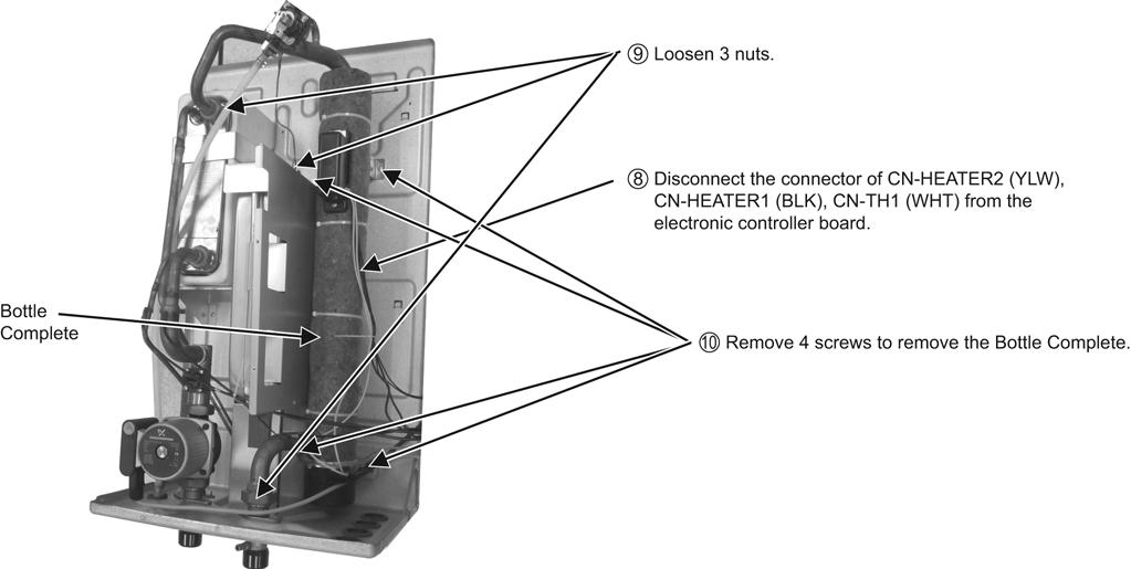
132 When reinstall the water pipe, use grease or water at the joining. When reinstall the water pipe, use grease or water at the joining. 132
133 19 Technical Data Operation Characteristics WH-SDC07C3E5 WH-UD07CE5-A Heating Characteristics at Different Outdoor Air Temperature Condition Outdoor air temperature : 7 C (DBT), 6 C (WBT) Indoor water inlet temperature : 30 C Indoor water outlet temperature : 35 C Piping length : 7m 133
134 Cooling Characteristics at Different Outdoor Air Temperature Condition Outdoor air temperature : 35 C (DBT), - C (WBT) Indoor water inlet temperature : 12 C Indoor water outlet temperature : 7 C Piping length : 7m 134
135 Heating Characteristics at Different Piping Length Condition Outdoor air temperature : 7 C (DBT), 6 C (WBT) Indoor water inlet temperature : 30 C Indoor water outlet temperature : 35 C Piping length : 7m 135
136 Cooling Characteristics at Different Piping Length Condition Outdoor air temperature : 35 C (DBT), - C (WBT) Indoor water inlet temperature : 12 C Indoor water outlet temperature : 7 C Piping length : 7m 136
137 WH-SDC09C3E5 WH-UD09CE5-A Heating Characteristics at Different Outdoor Air Temperature Condition Outdoor air temperature : 7 C (DBT), 6 C (WBT) Indoor water inlet temperature : 30 C Indoor water outlet temperature : 35 C Piping length : 7m 137
138 Cooling Characteristics at Different Outdoor Air Temperature Condition Outdoor air temperature : 35 C (DBT), - C (WBT) Indoor water inlet temperature : 12 C Indoor water outlet temperature : 7 C Piping length : 7m 138
139 Heating Characteristics at Different Piping Length Condition Outdoor air temperature : 7 C (DBT), 6 C (WBT) Indoor water inlet temperature : 30 C Indoor water outlet temperature : 35 C Piping length : 7m 139
140 Cooling Characteristics at Different Piping Length Condition Outdoor air temperature : 35 C (DBT), - C (WBT) Indoor water inlet temperature : 12 C Indoor water outlet temperature : 7 C Piping length : 7m 140
141 WH-SDC12C6E5 WH-UD12CE5-A Heating Characteristics at Different Outdoor Air Temperature Condition Outdoor air temperature : 7 C (DBT), 6 C (WBT) Indoor water inlet temperature : 30 C Indoor water outlet temperature : 35 C Piping length : 7m 141
142 Cooling Characteristics at Different Outdoor Air Temperature Condition Outdoor air temperature : 35 C (DBT), - C (WBT) Indoor water inlet temperature : 12 C Indoor water outlet temperature : 7 C Piping length : 7m 142
143 Heating Characteristics at Different Piping Length Condition Outdoor air temperature : 7 C (DBT), 6 C (WBT) Indoor water inlet temperature : 30 C Indoor water outlet temperature : 35 C Piping length : 7m 143
144 Cooling Characteristics at Different Piping Length Condition Outdoor air temperature : 35 C (DBT), - C (WBT) Indoor water inlet temperature : 12 C Indoor water outlet temperature : 7 C Piping length : 7m 144
145 WH-SDC14C6E5 WH-UD14CE5-A Heating Characteristics at Different Outdoor Air Temperature Condition Outdoor air temperature : 7 C (DBT), 6 C (WBT) Indoor water inlet temperature : 30 C Indoor water outlet temperature : 35 C Piping length : 7m 145
146 Cooling Characteristics at Different Outdoor Air Temperature Condition Outdoor air temperature : 35 C (DBT), - C (WBT) Indoor water inlet temperature : 12 C Indoor water outlet temperature : 7 C Piping length : 7m 146
147 Heating Characteristics at Different Piping Length Condition Outdoor air temperature : 7 C (DBT), 6 C (WBT) Indoor water inlet temperature : 30 C Indoor water outlet temperature : 35 C Piping length : 7m 147
148 Cooling Characteristics at Different Piping Length Condition Outdoor air temperature : 35 C (DBT), - C (WBT) Indoor water inlet temperature : 12 C Indoor water outlet temperature : 7 C Piping length : 7m 148
149 WH-SDC16C6E5 WH-UD16CE5-A Heating Characteristics at Different Outdoor Air Temperature Condition Outdoor air temperature : 7 C (DBT), 6 C (WBT) Indoor water inlet temperature : 30 C Indoor water outlet temperature : 35 C Piping length : 7m 149
150 Cooling Characteristics at Different Outdoor Air Temperature Condition Outdoor air temperature : 35 C (DBT), - C (WBT) Indoor water inlet temperature : 12 C Indoor water outlet temperature : 7 C Piping length : 7m 150
151 Heating Characteristics at Different Piping Length Condition Outdoor air temperature : 7 C (DBT), 6 C (WBT) Indoor water inlet temperature : 30 C Indoor water outlet temperature : 35 C Piping length : 7m 151
152 Cooling Characteristics at Different Piping Length Condition Outdoor air temperature : 35 C (DBT), - C (WBT) Indoor water inlet temperature : 12 C Indoor water outlet temperature : 7 C Piping length : 7m 152
153 19.2. Heating Capacity Table WH-SDC07C3E5 WH-UD07CE5-A LWC Tamb HC IP HC IP HC IP HC IP HC IP HC IP HC: Heating Capacity (kw) IP: Power Input (kw) LWC: Leaving Water Condenser Temperature ( C) Tamb: Ambient Temperature ( C) WH-SDC09C3E5 WH-UD09CE5-A LWC Tamb HC IP HC IP HC IP HC IP HC IP HC IP HC: Heating Capacity (kw) IP: Power Input (kw) LWC: Leaving Water Condenser Temperature ( C) Tamb: Ambient Temperature ( C) WH-SDC12C6E5 WH-UD12CE5-A LWC Tamb HC IP HC IP HC IP HC IP HC IP HC IP HC: Heating Capacity (kw) IP: Power Input (kw) LWC: Leaving Water Condenser Temperature ( C) Tamb: Ambient Temperature ( C) 153
154 WH-SDC14C6E5 WH-UD14CE5-A LWC Tamb HC IP HC IP HC IP HC IP HC IP HC IP HC: Heating Capacity (kw) IP: Power Input (kw) LWC: Leaving Water Condenser Temperature ( C) Tamb: Ambient Temperature ( C) WH-SDC16C6E5 WH-UD16CE5-A LWC Tamb HC IP HC IP HC IP HC IP HC IP HC IP HC: Heating Capacity (kw) IP: Power Input (kw) LWC: Leaving Water Condenser Temperature ( C) Tamb: Ambient Temperature ( C) Cooling Capacity Table MODELS SDC07 SDC09 SDC12 SDC14 SDC16 LWC Tamb TC IP TC IP TC IP TC IP TC IP TC: Cooling Capacity (kw) IP: Power Input (kw) LWC: Leaving Water Condenser Temperature ( C) Tamb: Ambient Temperature ( C) 154


155 19.4. Hydraulic Pump Performance (07C3 & 09C3) (12C6, 14C6 & 16C6) 155
AUTO COOL DRY FAN SPEED AIR SWING OFF ON TIMER TIMER OFF/ON FAN SPEED MODE TEMP AIR SWING TIMER ON SET OFF CANCEL AC RC SET CHECK CLOCK RESET
 AUTO COOL DRY MODE TIMER ON OFF TIMER OFF/ON TEMP ON TIMER FAN SPEED AIR SWING SET 1 2 3 FAN SPEED AIR SWING OFF CANCEL AC RC SET CHECK CLOCK RESET Order No: PAPAMY1611008CE Indoor Unit CS-MPS9SKH CS-MPS12SKH
CU-3E23CBPG, CU- 4E27CBPG,
 Order No. PHAAM0810051C2 Air Conditioner Indoor Unit Outdoor Unit CS-E7JKEW CU-E7JKE CS-E9JKEW CU-E9JKE CS-E12JKEW CU-E12JKE CS-E15JKEW CU-E15JKE CS-E15JKEW CU-E15JKE-1 CS-E7JKEW-3 CU-E7JKE-3 CS-E9JKEW-3
Destination Europe WARNING
 Order No: PAPAMY1406071CE Indoor Unit CS-E12QD3EAW Outdoor Unit CU-E12QD3EA Destination Europe Please file and use this manual together with the service manual for Model No. CU-2E15PBE CU-2E18PBE CU-3E18PBE
Air-to-Water Hydromodule + Tank WH-UX12FE5 WH-UD12FE5 WH-UD16FE5. Destination Europe WARNING
 Order : PAPAMY420CE Air-to-Water Hydromodule + Tank Indoor Unit WH-ADC26G6E5 Outdoor Unit WH-UX09FE5 WH-UX2FE5 WH-UD2FE5 WH-UD6FE5 Destination Europe WARNING This service information is designed for experienced
TABLE OF CONTENTS. Air Conditioner CS-MRE12MKE
 Order No. PHAAM1103074C8 Indoor Unit CS-MRE7MKE CS-MRE9MKE CS-MRE12MKE Air Conditioner Outdoor Unit CU-2RE15MBE CU-2RE18MBE TABLE OF CONTENTS PAGE 1 Safety Precautions-----------------------------------------------
Air Conditioner CONTENTS CS-E18EKU CU-E18EKU CS-E21EKU CU-E21EKU. Order No: MAC C1
 Order No: MAC0512115C1 CS-E18EKU CU-E18EKU CS-E21EKU CU-E21EKU Air Conditioner CONTENTS Page Page 1 Safety Precautions 3 2 Specification 5 2.1. CS-E18EKU CU-E18EKU 5 2.2. CS-E21EKU CU-E21EKU 7 3 Location
TABLE OF CONTENTS. Air Conditioner CS-E24GKES CU-E24GKE CS-E28GKE CU-E28GKE
 Order No. MAC0701008C2 CS-E24GKES CU-E24GKE CS-E28GKE CU-E28GKE Air Conditioner TABLE OF CONTENTS PAGE 1 Safety Precautions----------------------------------------------- 2 2 Specifications -----------------------------------------------------
TABLE OF CONTENTS. Air Conditioner. Indoor Unit Outdoor Unit CS-NE9LKE CU-NE9LKE CS-NE12LKE CU-NE12LKE CS-XE9LKE-5 CU-NE9LKE CS-XE12LKE-5 CU-NE12LKE
 Order No. PHAAM1007139C2 Air Conditioner Indoor Unit Outdoor Unit CS-NE9LKE CU-NE9LKE CS-NE12LKE CU-NE12LKE CS-XE9LKE-5 CU-NE9LKE CS-XE12LKE-5 CU-NE12LKE TABLE OF CONTENTS PAGE 1 Safety Precautions-----------------------------------------------
Air-to-Water Hydromodule + Tank WH-UD05HE5-1 WH-UD07HE5-1 WH-UD09HE5-1. Destination Europe Turkey
 Order : PAPAMY1607068CE Air-to-Water Hydromodule + Tank Indoor Unit WH-ADC0309H3E5 Outdoor Unit WH-UD03HE5-1 WH-UD05HE5-1 WH-UD07HE5-1 WH-UD09HE5-1 Destination Europe Turkey WARNING This service information
TABLE OF CONTENTS. Air Conditioner CS-NE7GKE CU-NE7GKE CS-NE9GKE CU-NE9GKE CS-NE12GKE CU-NE12GKE
 Order No. MAC0705021C2 Air Conditioner CS-NE7GKE CU-NE7GKE CS-NE9GKE CU-NE9GKE CS-NE12GKE CU-NE12GKE TABLE OF CONTENTS PAGE 1 Safety Precaution ------------------------------------------------ 2 2 Specifications
CS-XE9EKE CU-XE9EKE CS-XE12EKE CU-XE12EKE
 Order No. MAC0512111C8 Air Conditioner CS-XE9EKE CU-XE9EKE CS-XE12EKE CU-XE12EKE TABLE OF CONTENTS PAGE 1 Safety Precautions----------------------------------------------- 3 2 Specifications -----------------------------------------------------
TABLE OF CONTENTS. Air Conditioner
 Order No. MAC0804027A2 Air Conditioner CS-E9GFEW-2 CU-E9GFE-2 CS-E12GFEW-2 CU-E12GFE-2 CS-E18GFEW-2 CU-E18GFE-2 CU-2E15GBE CU-3E18EBE CU-3E23CBPG CU-4E27CBPG Please file and use this manual together with
CS-E18NKUA CS-E24NKUA CU-E18NKUA CU-E24NKUA TABLE OF CONTENTS WARNING
 Order No: PAPAMY1204088CE Indoor Unit CS-E18NKUA CS-E24NKUA Outdoor Unit CU-E18NKUA CU-E24NKUA WARNING This service information is designed for experienced repair technicians only and is not designed for
WH-TD20B3E5 WH-TD30B3E5
 Order No: PHAAM1004143C2 WH-TD20B3E5 WH-TD30B3E5 WARNING This service information is designed for experienced repair technicians only and is not designed for use by the general public. It does not contain
WH-UD03HE5 WH-UD05HE5 WH-SDC03H3E5 WH-SDC05H3E5. Destination Europe Turkey WARNING
 Order No: PAPAMY1509111CE Indoor Unit WH-SDC03H3E5 WH-SDC05H3E5 Outdoor Unit WH-UD03HE5 WH-UD05HE5 Destination Europe Turkey WARNING This service information is designed for experienced repair technicians
INSTALLATION MANUAL. Split-type Air Conditioner (Cooling and Heating) Outdoor Unit UQB09JJWC UQB12JJWC. Indoor Unit AQB09JJWC AQB12JJWC
 Outdoor Unit UQB09JJWC UQB12JJWC. Indoor Unit AQB09JJWC AQB12JJWC") AQB09JJ6WC_IM_E_2585 2006.4.17 4:26 PM Page 17 INSTALLATION MANUAL Indoor Unit AQB09JJWC AQB12JJWC Outdoor Unit UQB09JJWC UQB12JJWC ENGLISH FRANÇAIS ESPAÑOL Split-type Air Conditioner (Cooling and Heating)
AQB09JJ6WC_IM_E_2585 2006.4.17 4:26 PM Page 17 INSTALLATION MANUAL Indoor Unit AQB09JJWC AQB12JJWC Outdoor Unit UQB09JJWC UQB12JJWC ENGLISH FRANÇAIS ESPAÑOL Split-type Air Conditioner (Cooling and Heating)
CS-RE9JKX-1 CS-RE12JKX-1 CS-RE15JKX-1 CU-RE9JKX-1 CU-RE12JKX-1 CU-RE15JKX-1 TABLE OF CONTENTS WARNING
 Order No: PHA-AG1002007C2 Indoor Unit CS-RE9JKX-1 CS-RE12JKX-1 CS-RE15JKX-1 Outdoor Unit CU-RE9JKX-1 CU-RE12JKX-1 CU-RE15JKX-1 WARNING This service information is designed for experienced repair technicians
CS-UE9PKE CS-UE12PKE CU-UE9PKE CU-UE12PKE TABLE OF CONTENTS WARNING
 Order No: PAPAGZ121215CE Indoor Unit CS-UE9PKE CS-UE12PKE Outdoor Unit CU-UE9PKE CU-UE12PKE WARNING This service information is designed for experienced repair technicians only and is not designed for
CU-YE9MKE CU-YE12MKE CU-YE18MKE CS-YE9MKE CS-YE12MKE CS-YE18MKE TABLE OF CONTENTS WARNING
 Order No: PHA-AG1102003C2 Indoor Unit CS-YE9MKE CS-YE12MKE CS-YE18MKE Outdoor Unit CU-YE9MKE CU-YE12MKE CU-YE18MKE WARNING This service information is designed for experienced repair technicians only and
AOYG18LFC OUTDOOR UNIT INSTALLATION MANUAL INSTALLATION MANUAL. For authorized service personnel only. PART NO
 AOYG8LFC OUTDOOR UNIT INSTALLATION MANUAL INSTALLATION MANUAL For authorized service personnel only. English PART NO. 93778639 93778639_IM.indb /20/20 6:07:25 PM AIR CONDITIONER OUTDOOR UNIT INSTALLATION
DC INVERTER MULTI-SYSTEM AIR CONDITIONER
 TECHNICAL & SERVICE MANUAL OUTDOOR UNIT : CU-3KE19NBU CU-4KE24NBU CU-4KE31NBU DC INVERTER MULTI-SYSTEM AIR CONDITIONER Capacity at 0V 19,100 BTU/h,200 BTU/h 30,600 BTU/h Outdoor Model No. CU-3KE19NBU CU-4KE24NBU
INSTALLATION MANUAL. Split-type Air Conditioner (Cooling and Heating) Indoor Unit AQB18J6WC AQB24J2WC. Outdoor Unit UQB18J6WC UQB24J2WC
 Indoor Unit AQB18J6WC AQB24J2WC. Outdoor Unit UQB18J6WC UQB24J2WC") AQB8J6WC_IM_E_25864 2006.4.4 3:29 PM Page 7 INSTALLATION MANUAL Indoor Unit AQB8J6WC AQB24J2WC Outdoor Unit UQB8J6WC UQB24J2WC ENGLISH FRANÇAIS ESPAÑOL Split-type Air Conditioner (Cooling and Heating)
AQB8J6WC_IM_E_25864 2006.4.4 3:29 PM Page 7 INSTALLATION MANUAL Indoor Unit AQB8J6WC AQB24J2WC Outdoor Unit UQB8J6WC UQB24J2WC ENGLISH FRANÇAIS ESPAÑOL Split-type Air Conditioner (Cooling and Heating)
WARNING PRECAUTION OF LOW TEMPERATURE
 Order No: PAPAMY709003CE Mono Bloc Unit WH-MDC05H3E5 WH-MDC07H3E5 WH-MDC09H3E5 Destination Europe Turkey WARNING This service information is designed for experienced repair technicians only and is not
CU-S9NKV-7 CU-S12NKV-7 CU-S18NKV-7 CU-S22NKV-7 CS-S9NKV-7 CS-S12NKV-7 CS-S18NKV-7 CS-S22NKV-7 WARNING
 Order No: PAPAMY1206010CE Indoor Unit CS-S9NKV-7 CS-S12NKV-7 CS-S18NKV-7 CS-S22NKV-7 Outdoor Unit CU-S9NKV-7 CU-S12NKV-7 CU-S18NKV-7 CU-S22NKV-7 WARNING This service information is designed for experienced
SINGLE - ZONE Ductless Split System Heat Pumps Installation, Operation & Maintenance Manual
 Presents SINGLE - ZONE Ductless Split System Heat Pumps Installation, Operation & Maintenance Manual 9k,12k 18k 24k, 30k, 36k ECR International, Inc. 2201 Dwyer Avenue, Utica NY 13501 Phone: 800.325.5479
INSTALLATION MANUAL COMFORT...BUILT TO LAST. 9,000, 12,000 and 18,000 BTU SINGLE-ZONE DUCTLESS MINI-SPLIT SYSTEM Heat Pump
 COMFORT...BUILT TO LAST 9,000, 12,000 and 18,000 BTU SINGLE-ZONE DUCTLESS MINI-SPLIT SYSTEM Heat Pump INSTALLATION MANUAL INDOOR UNIT: 1PAMSH09-SZW-14.5 1PAMSH09-SZW-15 1PAMSH12-SZW-15 1PAMSH18-SZW-15
Installation and Operation Manual. CMA12SB-0 Series. Horizontal/Side Discharge Condensing Units
 Installation and Operation Manual CMA12SB-0 Series Horizontal/Side Discharge Condensing Units 517.787.2100 www.marsdelivers.com www.heatcontroller.com Heat Controller CONTENTS PAGE 1. PRES... 1 2. INSTALLATION
IMPORTANT SAFETY NOTICE
 Order No: PAPAMY703052CE Indoor Unit CS-TE20TKEW CS-TE25TKEW CS-TE35TKEW CS-TE42TKEW Outdoor Unit CU-TE20TKE CU-TE25TKE CU-TE35TKE CU-TE42TKE Destination Europe Turkey Please file and use this manual together
CU-RE18RKE CU-RE24RKE CS-RE18RKEW CS-RE24RKEW. Destination Europe L.America Turkey WARNING
 Order No: PAPAMY502047CE Indoor Unit CS-RE8RKEW CS-RE24RKEW Outdoor Unit CU-RE8RKE CU-RE24RKE Destination Europe L.America Turkey WARNING This service information is designed for experienced repair technicians
INSTALLATION INSTRUCTIONS
 INSTALLATION INSTRUCTIONS Solenoid Valve Kit For 3WAY VRF System CZ-PXXXHR3 () IMPORTANT! Please Read Before Starting This solenoid Valve kit must be installed by the sales dealer or installer. This information
AUT O HE AT COOL DRY FAN SPEE D AIR SW ING OFF/ON MODE TEMP AIR SW ING POWERFUL/ QUIET TIMER ON SET OFF CANCEL SET CHECK CLOCK RESET WARNING
 AUT O HE AT COOL DRY POWERFUL/ QUIET FAN SPEE D AC AIR SW ING SET CHECK CLOCK RESET FAN SPEED AIR SW ING RC Order No: PAPAMY502046CE Indoor Unit CS-RE9RKEW CS-RE2RKEW CS-RE5RKEW Outdoor Unit CU-RE9RKE
INVERTER SPLIT - TYPE
 INVERTER SPLIT - TYPE ISSUE No 2 DATE 04/09/08 P/No 2020323A2868 CONTENTS SAFETY PRECAUTIONS Warning 2 Operating temperature 2 BEFORE INSTALLATION Tools needed for installation 3 Items required for installing
Air Conditioner CONTENTS CS-TE9DKE CU-TE9DKE CS-TE12DKE CU-TE12DKE. Order No. RAC C2
 Order No. RAC0502005C2 Air Conditioner CS-TE9DKE CU-TE9DKE CS-TE12DKE CU-TE12DKE CONTENTS Page Page 1 Features 2 2 Functions 3 2.1. Remote Control 3 2.2. Indoor Unit 4 2.3. Outdoor unit 5 3 Product Specifications
Choosing the installation site. Installation. 07 Choosing the installation site
 Installation Installation warnings: 1. Carefully read the installation manual before beginning. 2. Follow each step as shown. 3. Observe all local, state, and national electrical codes and by qualified,
WARNING IMPORTANT SAFETY NOTICE
 Order No: PAPAMY8020CE Indoor Unit CS-FZ25UKE CS-FZ35UKE CS-FZ50UKE CS-FZ60UKE Outdoor Unit CU-FZ25UKE CU-FZ35UKE CU-FZ50UKE CU-FZ60UKE Destination Europe Turkey FAN SPEED FAN SPEED WARNING This service
Split-type Air-Conditioner INSTALLATION MANUAL CONTENTS FOR INSTALLER MXZ-3B54VA MXZ-4B71VA. English
 Split-type Air-Conditioner MXZ-3B54VA MXZ-4B71VA INSTALLATION MANUAL English Refer to the installation manual of each indoor unit for indoor unit installation. IMPORTANT NOTES TO COMPLY WITH THE REQUIREMENTS
1. BEFORE INSTALLATION
 ENGLISH SPLIT-TYPE AIR CONDITIONERS INSTALLATION MANUAL MSZ-D30/36NA MSY-D30/36NA JG79A061H09 Phillips screwdriver Level Scale Utility knife or scissors 3 in. (75 mm) hole saw Torque wrench Wrench (or
FLOOR-STANDING TYPE AIR CONDITIONER INSTALLATION MANUAL
 FLOOR-STANDING TYPE AIR CONDITIONER INSTALLATION MANUAL CONTENTS SAFETY PRECAUTIONS Warning... Caution... INSTALLATION INSTRUCTIONS Accessories...;...3 Selecting installation place...4 PIPE CONNECTION
Room Air Conditioner CONTENTS CS-E9BKP CU-E9BKP5 CS-E12BKP CU-E12BKP5. Order No: MAC C2
 Order No: MAC008C Room Air Conditioner CS-E9BKP CU-E9BKP5 CS-EBKP CU-EBKP5 CONTENTS Page Page Features Functions Product Specifications 6 Dimensions 0 5 Refrigeration Cycle Diagram 6 Block Diagram 7 Wiring
DAIKIN AIR CONDITIONER
 3P226011-1A M07B242A DAIKIN AIR CONDITIONER Two-dimensional bar code is a code for manufacturing. Safety Precautions (1) Read these Safety Precautions carefully to ensure correct installation. This manual
Air Conditioner. Outdoor Unit CU-2Z35TBE CU-2Z41TBE CU-2Z50TBE. Destination Europe
 Order No: PAPAMY1702035CE Air Conditioner Outdoor Unit CU-2Z35TBE CU-2Z41TBE CU-2Z50TBE Destination Europe Please file and use this manual together with the service manual for Model No. CS-MZ16TKE CS-Z20TKEW
TECHNICAL DATA & SERVICE MANUAL
 TECHNICAL DATA & SERVICE MANUAL OUTDOOR UNIT: GRF188R5TAA GRF228R5TAA GRF228R7TAA SPLIT SYSTEM AIR CONDITIONER Model No. Product Code No. GRF188R5TAA 38.7107.083 GRF228R5TAA 38.7107.084 GRF228R7TAA 38.7107.085
1. BEFORE INSTALLATION
 ENGLISH SPLIT-TYPE AIR CONDITIONERS INSTALLATION MANUAL MSZ-D30/36NA MSY-D30/36NA JG79A061H01 Phillips screwdriver Level Scale Utility knife or scissors 3 in. (75 mm) hole saw Torque wrench Wrench (or
CU-B24DBE5 CS-F28DTE5 CU-B28DBE5 CS-F28DTE5 CU-B28DBE8 CS-F34DTE5 CU-B34DBE5 CS-F34DTE5 CU- B34DBE8 CS-F43DTE5 CU-B43DBE8 CS-F50DTE5 CU-B50DBE8,
 Order No. MAC0605029C2 Air Conditioner CS-F18DTE5 CU-B34DBE5 CS-F18DTE5 CU-B34DBE8 CS-F24DTE5 CU-B43DBE8 CS-F28DTE5 CU-B50DBE8 Please file and use this manual together with the service manual for Model
Split-type Air-Conditioner
 Split-type Air-Conditioner MXZ-2D52VA Installation Manual For INSTALLER This manual only describes the installation of outdoor unit. When installing the indoor unit, refer to the installation manual of
DC INVERTER MULTI-SYSTEM AIR CONDITIONER
 TECHNICAL & SERVICE MANUAL OUTDOOR UNIT : CLM97 CLM7 CLM7 FILE NO. Destination: North America DC INVERTER MULTI-SYSTEM AIR CONDITIONER Capacity at 0V 9,700 BTU/h,00 BTU/h 0,600 BTU/h Outdoor Model No.
FLOOR-STANDING SPLIT TYPE ROOM AIR CONDITIONER
 Before using your air conditioner, please read this manual carefully and keep it for future reference. FLOOR-STANDING SPLIT TYPE ROOM AIR CONDITIONER Please read this installation manual completely before
INSTALLATION INSTRUCTIONS
 INSTALLATION INSTRUCTIONS - Wall-mount indoor unit - OPERATING LIMITS Cooling Maximum conditions Heating Maximum conditions Outdoor temperature : 122 F (50 C) D.B. Outdoor temperature : 75 F (24 C) D.B.
Installation Manual. KS Series KS09 KS12 KS18 KS24 KS28. J3387_Kaden_Installer_Manual_ indd 1
 Wall Mounted AIR CONDITIONER Installation Manual KS Series KS09 KS12 KS18 KS24 KS28 J3387_Kaden_Installer_Manual_050917.indd 1 5/09/2017 9:07 AM J3387_Kaden_Installer_Manual_050917.indd 2 5/09/2017 9:07
SPLIT-TYPE ROOM AIR CONDITIONER
 Before using your air conditioner, please read this manual carefully and keep it for future reference SPLIT-TYPE ROOM AIR CONDITIONER Please read this installation manual completely before installing the
Safety Precautions (1)
") 3P207257-3D M07B061D DAIKIN AIR CONDITIONER Two-dimensional bar code is a code for manufacturing. Safety Precautions (1) Read these Safety Precautions carefully to ensure correct installation. This manual
3P207257-3D M07B061D DAIKIN AIR CONDITIONER Two-dimensional bar code is a code for manufacturing. Safety Precautions (1) Read these Safety Precautions carefully to ensure correct installation. This manual
Split-type Air-Conditioner
 Split-type Air-Conditioner MXZ-2E52VAD MXZ-3E54VAD MXZ-4E71VAD Installation Manual For INSTALLER This manual only describes the installation of outdoor unit. When installing the indoor unit, refer to the
1. BEFORE INSTALLATION
 ENGLISH SPLIT-TYPE AIR CONDITIONERS INSTALLATION MANUAL MSZ-FH09/12/15NA JG79A805H01 When installing multi units, refer to the installation manual of the multi unit for outdoor unit installation. Phillips
Air Conditioner CONTENTS CS-V18DKE CU-V18DKE CS-V24DKE CU-V24DKE. Order No. MAC C2
 Order No. MAC0410044C2 CS-V18DKE CU-V18DKE CS-V24DKE CU-V24DKE Air Conditioner CONTENTS Page Page 1 Features 2 2 Functions 3 2.1. Remote Control 3 2.2. Indoor Unit 4 2.3. Outdoor Unit 5 3 Product Specifications
TECHNICAL DATA & SERVICE MANUAL SPLIT SYSTEM AIR CONDITIONER INDOOR UNIT: AW22AL AW28AL AW38AL AW42AL AW22AL AW28AL AW38AL
 TECHNICAL DATA & SERVICE MANUAL INDOOR UNIT: AW22AL AW28AL AW38AL AW42AL SPLIT SYSTEM AIR CONDITIONER Model No. Product Code No. AW22AL 387030005 AW28AL 387030006 AW38AL 387030007 AW42AL 387030094 0.8180.467.0
Split-type Air-Conditioner
 Split-type Air-Conditioner MXZ-2C52VA Installation Manual For INSTALLER This manual only describes the installation of outdoor unit. When installing the indoor unit, refer to the installation manual of
CONTENTS INSTALLATION MANUAL HFC FOR INSTALLER R410A. utilized 1. THE FOLLOWING SHOULD ALWAYS BE OBSERVED FOR SAFETY... 2
 SPLIT-TYPE AIR CONDITIONER CONTENTS INSTALLATION MANUAL 1. THE FOLLOWING SHOULD ALWAYS BE OBSERVED FOR SAFETY... 2 Model MXZ-A26/32WV HFC utilized R410A 2. INSTALLATION DIAGRAM & ACCESSORIES... 2 3. SELECTING
1. BEFORE INSTALLATION
 ENGLISH SPLIT-TYPE AIR CONDITIONERS INSTALLATION MANUAL JG79A191H07 MSZ-GE06/09/12/15/18NA MSY-GE09/12/15/18NA When installing multi units, refer to the installation manual of the multi unit for outdoor
R32. Installation Manual Split Type Wall Mounted Air Conditioner. This appliance shall be installed in accordance with: REFRIGERANT
 SWING LRSWING Installation Manual Split Type Wall Mounted Air Conditioner COOL RUN C SPEED TURBO ON/OFF FAN COOL HEAT SWING SWING Rinnai Systems Models System Indoor Outdoor HSNRQ25B HINRQ25B HONRQ25B
Operating Instructions Air Conditioner
 F566113 Operating Instructions Air Conditioner Indoor Unit CS-E18HKR CS-E1HKR CS-E4HKR CS-E8HKR Outdoor Unit CU-E18HKR CU-E1HKR CU-E4HKR CU-E8HKR Before operating the unit, read these operating instructions
[FLARE CONNECTION TYPE] ATTENTION
![[FLARE CONNECTION TYPE] ATTENTION](/thumbs/88/117511702.jpg "[FLARE CONNECTION TYPE] ATTENTION") SPLIT-TYPE AIR CONDITIONERS Model MXZ-2A20NA [FLARE CONNECTION TYPE] HFC utilized R410A INSTALLATION MANUAL ATTENTION This manual mentions how to install only the outdoor unit, MXZ-2A20NA. As for the way
SPLIT-TYPE AIR CONDITIONERS Model MXZ-2A20NA [FLARE CONNECTION TYPE] HFC utilized R410A INSTALLATION MANUAL ATTENTION This manual mentions how to install only the outdoor unit, MXZ-2A20NA. As for the way
TECHNICAL DATA & SERVICE MANUAL
 TECHNICAL DATA & SERVICE MANUAL OUTDOOR UNIT: AE726SCL AE752SCL AE71SCL3 AE735SCL AE752SCL3 AE100SCL3 AE764SCL3 AE125SCL3 SPLIT SYSTEM AIR CONDITIONER Model No. AE726SCL AE735SCL AE752SCL AE752SCL3 AE764SCL3
Room Air Conditioner Service and Parts Manual
 Cool Dry Temp Mode Room Air Conditioner Service and Parts Manual F Fan Speed hr Timer 0n 0ff Money Saver Fan Only Auto Swing Power CP06 CP08 93011401_01 CONTENTS 1. PREFACE 1.1 SAFETY PRECAUTIONS...2 1.2
TECHNICAL DATA & SERVICE MANUAL
 TECHNICAL DATA & SERVICE MANUAL INDOOR UNIT: CAF97R5IAA CAF98MR5IAA CAF127R5IAA CAF128MR5IAA CAF187R5IAA SPLIT SYSTEM AIR CONDITIONER Model No. CAF97R5IAA CAF127R5IAA CAF187R5IAA CAF98MR5IAA CAF128MR5IAA
CU-Z7SKE CU-Z9SKE CU-Z12SKE CU-Z18SKE CS-XZ7SKEW CS-XZ9SKEW CS-XZ12SKEW CS-XZ18SKEW. Destination EU E.Europe L.America Turkey WARNING
 Order No: PAPAMY1604028CE Indoor Unit CS-XZ7SKEW CS-XZ9SKEW CS-XZ12SKEW CS-XZ18SKEW Outdoor Unit CU-Z7SKE CU-Z9SKE CU-Z12SKE CU-Z18SKE Destination EU E.Europe L.America Turkey WARNING This service information
Horizontal/Side Discharge Condensing Units
 INSTALLATION, OPERATION & MAINTENANCE MANUAL Horizontal/Side Discharge Condensing Units Models CMA12SD-0 CMA18SD-1 CMA24SD-1 CMA30SD-1 CMA36SD-1 CMA48SD-1 517.787.2100 www.marsdelivers.com Horizontal/Side
INSTALLATION MANUAL SPLIT TYPE ROOM AIR CONDITIONER (PART NO )
") SPLIT TYPE ROOM AIR CONDITIONER INSTALLATION MANUAL (PART NO. 9312791019-01) This air conditioner uses new refrigerant HFC (R410A). The basic installation work procedures are the same as conventional refrigerant
SPLIT TYPE ROOM AIR CONDITIONER INSTALLATION MANUAL (PART NO. 9312791019-01) This air conditioner uses new refrigerant HFC (R410A). The basic installation work procedures are the same as conventional refrigerant
TECHNICAL DATA & SERVICE MANUAL SPLIT SYSTEM AIR CONDITIONER OUTDOOR UNIT: AE22AC/ACL/AH AE28AC/ACL/AH AE38AC/ACL/AH AE42AC/ACL/AH
 TECHNICAL DATA & SERVICE MANUAL OUTDOOR UNIT: AE22AC/ACL/AH AE28AC/ACL/AH AE38AC/ACL/AH AE42AC/ACL/AH SPLIT SYSTEM AIR CONDITIONER Model No. Product Code No. AE22AH 387031006 AE28AH 387031007 AE38AH 387031008
Operating Instructions Air Conditioner
 alleru-buster F566894 Operating Instructions Air Conditioner Indoor Unit CS-RE9JKR CS-RE1JKR Outdoor Unit CU-RE9JKR CU-RE1JKR ENGLISH ~ 7 Before operating the unit, read these operating instructions thoroughly
1. BEFORE INSTALLATION
 ENGLISH SPLIT-TYPE AIR CONDITIONERS INSTALLATION MANUAL Model names are indicated in 1-3. JG79A145H05 Phillips screwdriver Level Scale Utility knife or scissors 75 mm hole saw Torque wrench Wrench (or
Mini-Split Air Conditioner
 Cassette Type Installation Manual New Released A-Cassette-600 Mini-Split Air Conditioner DC Inverter Cassette Type Unit All Model Numbers Table of Contents Installation Manual 2 3 Accessories... 04 Safety
Installation Instructions. For the 18 Built-In Dishwasher and Front Color Panels
 Installation Instructions For the 18 Built-In Dishwasher and Front Color Panels Printed in USA 154232102 Before You Begin DO NOT INSTALL DISHWASHER UNTIL YOU HAVE READ ALL INSTRUCTIONS. FOR YOUR SAFETY,
Inverter Air Source Heat Pump Monobloc system
 Inverter Air Source Heat Pump Monobloc system Product Data & Installation Manual AXAI-06M & AXAI-09M AXAI-12M & AXAI-15M TABLE OF CONTENT INSTRUCTIONS 1 This manual 1 Items inside product box. 2 Tools
INVERTER ONE-TWO/ONE-THREE/ONE-FOUR/ONE-FIVE SPLIT-TYPE AIR CONDITIONER
 INVERTER ONE-TWO/ONE-THREE/ONE-FOUR/ONE-FIVE SPLIT-TYPE AIR CONDITIONER Installation Manual IMPORTANT NOTE: Read this manual carefully before installing or operating your new air conditioning unit. Make
INSTALLATION MANUAL. R410A Split Series. Models RXS15LVJU RXS18LVJU. Installation manual R410A Split series. Manuel dinstallation Série split R410A
 INSTALLATION MANUAL R410A Split Series Installation manual R410A Split series English Manuel dinstallation Série split R410A Français Manual de instalación Serie Split R410A Español Models RXS15LVJU RXS18LVJU
1. BEFORE INSTALLATION
 ENGLISH SPLIT-TYPE AIR CONDITIONERS INSTALLATION MANUAL REFRIGERANT JG79Y335H01 Model names are indicated in 1-3. When installing multi units, refer to the installation manual of the multi unit for outdoor
1. BEFORE INSTALLATION
 ENGLISH SPLIT-TYPE AIR CONDITIONERS INSTALLATION MANUAL REFRIGERANT JG79B530H01 Model names are indicated in 1-3. Phillips screwdriver Level Scale Utility knife or scissors 75 mm hole saw Torque wrench
MXZ-4B80VA MXZ-5B100VA INSTALLATION MANUAL
 Split-type Air-Conditioner MXZ-4B80VA MXZ-5B100VA INSTALLATION MANUAL Refer to the installation manual of each indoor unit for indoor unit installation. English Deutsch Français Nederlands Español Italiano
Installation Manual PMV Kit RBM-PMV0363E RBM-PMV0903E
 EB99802801-1 Installation Manual RBM-PMV0363E RBM-PMV0903E Installation Manual English OUTDOOR UNIT SIDE UPPER INDOOR UNIT SIDE Thank you very much for purchasing TOSHIBA Air conditioner. Please read this
Air Conditioner. user installation & manual manual. imagine the possibilities
 ARFSSSBWK Series ARFSSSCUR AJ JNADCH Series Air Conditioner user installation & manual manual This manual is made with 100% recycled paper. imagine the possibilities Thank you for purchasing this Samsung
Installer manual AG-AA10. Air/air heat pump IHB GB AG-AA10-30 AG-AA10-40/50
 -30 Installer manual Air/air heat pump -40/50 IHB GB 1516-1 331554 Table of Contents 1 Important information 2 5 Installation 7 Safety information 2 Model combinations 7 Read before starting the installation
Installation Instructions
 40MAQ High Wall Ductless Split System Sizes 09 to 36 Installation Instructions NOTE: Read the entire instruction manual before starting the installation TABLE OF CONTENTS PAGE SAFETY CONSIDERATIONS 2 PARTS
R32 INSTALLATION MANUAL ENGLISH AIR CONDITIONER (SPLIT TYPE) Indoor unit RAS-10PKVPG-E RAS-13PKVPG-E RAS-16PKVPG-E
 Indoor unit RAS-10PKVPG-E RAS-13PKVPG-E RAS-16PKVPG-E") R32 INSTALLATION MANUAL AIR CONDITIONER (SPLIT TYPE) ENGLISH Indoor unit RAS-10PKVPG-E RAS-13PKVPG-E RAS-16PKVPG-E Outdoor unit RAS-10PAVPG-E RAS-13PAVPG-E RAS-16PAVPG-E 1121451198 EN CONTENTS PRES FOR
R32 INSTALLATION MANUAL AIR CONDITIONER (SPLIT TYPE) ENGLISH Indoor unit RAS-10PKVPG-E RAS-13PKVPG-E RAS-16PKVPG-E Outdoor unit RAS-10PAVPG-E RAS-13PAVPG-E RAS-16PAVPG-E 1121451198 EN CONTENTS PRES FOR
Operating Instructions Air Conditioner
 F56690 Operating Instructions Air Conditioner Indoor Unit CS-S9JKR CS-S1JKR Outdoor Unit CU-S9JKR CU-S1JKR Before operating the unit, read these operating instructions thoroughly and keep them for future
Inverter Air Conditioner Installation Manual GIN 090/GIN 091 GIN 120/GIN 121 GIN 180/GIN 181 GIN 240/GIN 241
 Inverter Air Conditioner Installation Manual GIN 090/GIN 091 GIN 120/GIN 121 GIN 180/GIN 181 GIN 240/GIN 241 Please read this user manual first! Dear Customer, Thank you for preferring a Beko product.
TECHNICAL DATA & SERVICE MANUAL
 TECHNICAL DATA & SERVICE MANUAL OUTDOOR UNIT:. TRIAL SPLIT SYSTEM AIR CONDITIONER Model No. Product Code No. 38.7107.102. 0.8180.611.02 09/2012 IMPORTANT! Please read before installation This air conditioning
1. BEFORE INSTALLATION
 ENGLISH SPLIT-TYPE AIR CONDITIONERS INSTALLATION MANUAL REFRIGERANT JG79B528H01 Model names are indicated in 1-3. Phillips screwdriver Level Scale Utility knife or scissors 75 mm hole saw Torque wrench
UltraV Series Outdoor Units
 INSTALLATION MANUAL UltraV Series Outdoor Units Models A-VMH18DU-1 A-VMH28TU-1 A-VMH36QU-1 517.787.2100 www.marsdelivers.com Table of Contents Installation Manual 1 2 3 4 5 Accessories... 4 Safety Precautions...
MULTI TYPE ROOM AIR CONDITIONERS INSTALLATION INSTRUCTIONS
 MULTI TYPE ROOM IR CONDITIONERS INSTLLTION INSTRUCTIONS Please read this instruction sheet completely before installing the product. When the power cord is damaged, replacement work shall be performed
INSTALLATION MANUAL. R410A Split Series. Model RXS24LVJU. Installation manual R410A Split series. Manual de instalación Serie Split R410A.
 INSTALLATION MANUAL R410A Split Series Installation manual R410A Split series English Français Manual de instalación Serie Split R410A Español Model RXS24LVJU Safety Precautions Read these Safety Precautions
GDDEM10 DEHUMIDIFIER
 GDDEM10 DEHUMIDIFIER SOCIABLE REMARK When using this dehumidifier in the European countries, the following information must be followed: DISPOSAL: Do not dispose this product as unsorted municipal waste.
OWNER S AND INSTALLATION MANUAL RAV-480FS2B/RAV-480AS2B RAV-600FS8B/RAV-600AS8B
 OWNER S AND INSTALLATION MANUAL RAV-480FS2B/RAV-480AS2B RAV-600FS8B/RAV-600AS8B P/N: 52FS2B54070-R CONTENTS PRECAUTIONS Important Safety Information Hints For Economical Operation Standard Safety Instructions
TECHNICAL & SERVICE MANUAL WINDOW TYPE AIR CONDITIONER SA 183A FILE NO. SA 183A REFERENCE NO. SM Destination Australia SA-183A
 TECHNICAL & SERVICE MANUAL SA 183A FILE NO. WINDOW TYPE AIR CONDITIONER Model No. Product Code No. SA-183A 1 851 006 96 Destination Australia SA 183A REFERENCE NO. SM700514 IMPORTANT! Please Read Before
ROOM AIR CONDITIONER INSTALLATION MANUAL
 ROOM AIR CONDITIONER INSTALLATION MANUAL (Inverter Split Type) Please read this installation manual completely before installing the product When the power cord is damaged, replacement work shall be performed
DUCTLESS MINI-SPLIT INSTALLATION MANUAL COMFORT...BUILT TO LAST
 COMFORT...BUILT TO LAST SINGLE ZONE DUCTLESS MINI-SPLIT INSTALLATION MANUAL 2PAMS SERIES Before using your air conditioner please read this manual carefully and keep it for future reference, along with
Installation/Instruction Manual
 1510876HC8902 Pressurized ventilators (for device cooling) Model Blade diameter (cm) Indoor or outdoor EF-20UYS-UL EF-25UAS-UL EF-30UBS-UL 20 25 30 Indoor Installation/Instruction Manual For customers
Room Air Conditioner CONTENTS CS-PV9CKE CU-PV9CKE CS-PV12CKE CU-PV12CKE
 Order Number: GMAC0311008C2 Room Air Conditioner CS-PV9CKE CU-PV9CKE CS-PV12CKE CU-PV12CKE CONTENTS Page Page 1 Functions 2 2 Product Specifications 5 3 Dimensions 9 4 Refrigeration Cycle Diagram 11 5
Operating Instructions Air Conditioner
 F56579 Operating Instructions Air Conditioner Indoor Unit Outdoor Unit CS-E18GKR CS-E1GKR CS-E4GKR CS-E8GKR CU-E18GKR CU-E1GKR CU-E4GKR CU-E8GKR Before operating the unit, read these operating instructions
Table of Contents. Installation Manual. Accessories Safety Precautions Installation Overview Installation Diagram.
 Table of Contents Installation Manual 1 2 3 Accessories...04 Safety Precautions...05 Installation Overview...06 4 Installation Diagram...07 5 Specifications...08 6 Outdoor Unit Installation... 09 a. Outdoor
Room Air Conditioner SERVICE MANUAL MODEL : LW6013ERY3. CAUTION
 www.zenithappliances.com Room Air Conditioner SERVICE MANUAL MODEL : LW6013ERY3 CAUTION BEFORE SERVICING THE UNIT, READ THE SAFETY PRECAUTIONS IN THIS MANUAL. ONLY FOR AUTHORIZED SERVICE PERSONNEL. CONTENTS