REFRIGERANT RECOVERY Log Book
|
|
|
- Sheryl Booth
- 5 years ago
- Views:
Transcription

1 REFRIGERANT RECOVERY Log Book
2 R E F R I G E R A N T L O G
3 1) Policy 2) Troubleshooting 3) Condensers Replaced 4) Compressors Replaced 5) Appliance Disposal 6) Accidental Venting 7) R22 NEW 8) R22 Recover CLEAN 9) R22 Recover BURNT 10) R410a NEW 11) R410a Recover CLEAN 12) R410a Recover BURNT
4 TAB 1
5 REFRIGERANT RECOVERY Refrigerant Certification and Recordkeeping May 13, 2015 As required by Section 608 of the Federal Clean Air Act, all persons involved in work which involves refrigerant, the access to a sealed refrigeration or air conditioning system, or the disposal of equipment containing refrigerant must have the appropriate Environmental Protection Agency (EPA) certification. There are (4) four categories of technician certification: TYPE I TYPE II TYPE III UNIVERSAL Persons who maintain, service, or repair small appliances, i.e., refrigerators, freezers, window A/C units, dehumidifiers, under-the-counter ice makers, vending machines, and drinking water coolers. Persons who maintain, service, repair, or dispose of high pressure appliances, i.e., conventional split system heat pump and air conditioner systems. Persons who maintain, service, repair, or dispose of low pressure appliances, i.e., chiller systems. This classification indicates that the individual is certified in all of the abovementioned categories. CERTIFICATION RECORDKEEPING The Community Manager shall be responsible for the recordkeeping and archival of certification documents, and shall ultimately be responsible for compliance with all the requirements of this policy. 1. For each current employee who is certified, the Community Manager shall complete the following: a. Confirm a legible copy of the employee s certification card is filed in the Refrigerant Recovery Log Book. b. Post a scanned copy onto the Benchmark X-Drive in the Employee Certification Cards folder. c. Forward a scanned copy of current and/or updated certification cards to Benchmark s Human Resources Director. 2. For former employees, if certification cards are available, the Community Manager shall file a legible copy of certification card(s) in the Refrigerant Recovery Log Book and post a scanned copy onto the Benchmark X-Drive in the Employee Certification Cards folder. 3. For any employee who has come from another Benchmark community and has completed any service request dealing with refrigerant or the disposal of appliances containing refrigerants while at the community, the Community Manager shall post a scanned copy onto the Benchmark X-Drive in the Employee Certification Cards folder.
6 GENERAL RECORDKEEPING In accordance with the Environmental Protection Agency (EPA) recordkeeping requirements, the Service Manager shall maintain the information listed below and ensure the documentation is being completed timely and accurately by all service team members. As such, the Service Manager shall maintain the following: 1. Documentation for the service, maintenance, repair, or disposal of appliances which contain refrigerant. a. Documentation shall include refrigerant tracking logs, appliance disposal forms, service requests in OneSite, and OneSite invoices for the purchase of refrigerants and appliances containing refrigerants. b. Digital information in OneSite is sufficient documentation; no additional paper hardcopy is required to be saved or filed. 2. Records indicating the specific equipment or appliance containing refrigerant which was serviced, maintained, repaired, or disposed. 3. Records indicating the amount of refrigerant used during the service, maintenance, or repair of each specific system or appliance containing refrigerant. 4. Records indicating the amount of refrigerant recovered or recycled during the service, maintenance, repair or disposal of any system or appliance containing refrigerant. 5. A copy of each receipt or invoice for the purchase of any refrigerant. a. Digital information in OneSite is sufficient documentation; no additional paper hardcopy is required to be saved or filed. 6. Maintain and monitor the Refrigerant Recovery Logs as needed for completeness and accuracy. 7. Periodically verify the weight of refrigerant cylinders which are in use, and confirm the tracking log is up to date and accurate. a. These periodic checks shall occur at least every 30 days during the air conditioning season or heat pump heating season when refrigerants have been used or recovered. 8. Upon delivery of a refrigerant cylinder to the community, clearly label the cylinder with a unique number, weigh the refrigerant, and log the corresponding weight into the refrigerant tracking sheet. a. Typically, the date the cylinder was delivered is used as the unique tracking number, followed by an additional letter or number if multiple cylinders are received on the same date. For example: 5/12/2015-A, 5/12/2015-B, etc. 9. Scanned copies of the Refrigerant Logs, Appliance Disposal forms, Accidental Venting Reports, and all other documentation in the Refrigerant Recovery Log Book shall be uploaded and posted onto the Benchmark X-Drive. a. Recurring service requests will automatically be generated in OneSite for these tasks. If these service requests are not automatically generated, post files monthly. b. Pages which have previously been scanned and posted onto the drive do not need to be re-scanned and re-posted.
7 10. As long as all EPA Log documentation has been scanned and properly posted onto the Benchmark X-Drive in the appropriate folders, and the files are named according to the current policy, log pages which are older than 12 months may be removed from the binder and destroyed. CERTIFIED EMPLOYEES 1. If required by Federal, State or Local code, certified employees must carry a wallet size certification card with them while handling refrigerant or when servicing or disposing of equipment which contains refrigerant. ALL EMPLOYEES 1. Special warning to all employees: any individual found venting refrigerant is subject to disciplinary action up to and including termination, in addition to any Federal, State, or Local fines which may be imposed.
8 POLICY ACKNOWLEDGEMENT By signing below, I hereby acknowledge that I have read and understand Benchmark s Refrigerant Certification and Recordkeeping policies, and that I am familiar with the Environmental Protection Agency s (EPA) requirements for the proper use and handling of refrigerants and other substances covered under the Clean Air Act. I further acknowledge that I will promptly and accurately maintain required documentation and usage records, and I understand that failure to comply with the requirements of this policy or the requirements of the EPA Clean Air Act will result in disciplinary action leading up to or including termination. Printed Name Signature Date
9 EPA CERTIFICATION VERIFICATION As a Benchmark Management service associate, it is important that we verify your EPA recovery certification and comply with all EPA regulations. Please Check the Appropriate Certification that You Currently Have TYPE I small appliances TYPE II residential split systems TYPE III low pressure chillers UNIVERSAL Please list the name of the testing facility that your certification is with on the line below: Please Print Name of Testing Facility and contact information (if known) Print Name Signature Date Please have your certification card available so that it can be photocopied and attached to this form. NOTE: In the past it was a common procedure to list the person s Social Security Number on their certification card. DO NOT copy the Social Security Number if present on the certification card.
10 TAB 2


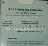
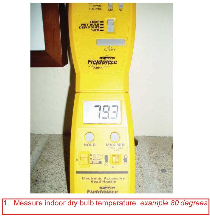
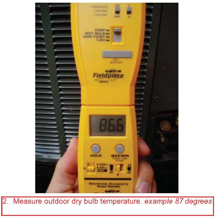
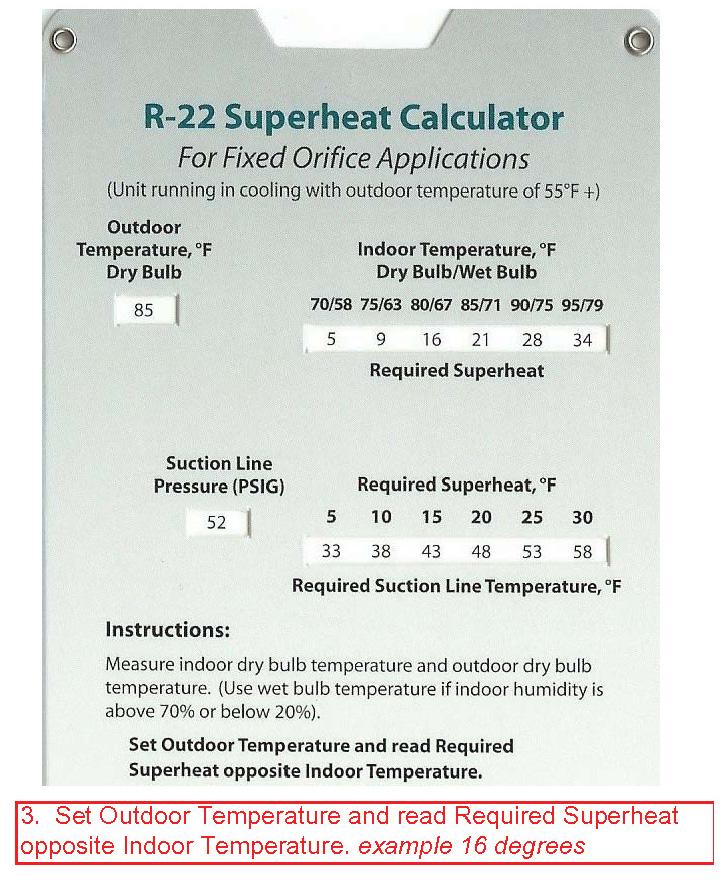
11 Guide to Using Superheat and Subcooling Calculators


12 R-22 Superheat and Subcooling Calculators
13
14
15
16
17
18
19 Page 1
20 A/C Troubleshooting Guide I. WHAT TO DO FIRST (inside) A. Go to thermostat 1. Put lever in Manual fan position. a. If blower runs: volt circuit is intact (including relay and transformer) volt circuit is intact. b. If blower motor will not run: 1. Power Failure. 2. Blower fuse or tripped breaker. 3. Open disconnect switch. 4. Faulty wiring. 5. Open in control circuit (green circuit). 6. Loose terminals. 7. Control transformer bad. 8. Blower relay. 9. Bad run capacitor. 10. Thermostat. 11. Motor overload switch open because of dirty blower. 2. Make sure lever is in cool position. 3. Make sure temperature setting is calling for cooling. 4. Check thermostat for dirt or loose wires and bulb operation. B. Ask resident how long A/C has been turned on. C. Ask resident what they did with thermostat and then instruct them. D. Be sure cold air return is NOT blocked. E. Be sure air is un-obstructed to thermostat. F. Be sure no windows are open. G. Be sure all interior doors have been open. H. Be sure air supplies are open. I. Check furnace filters and evaporator coil for dirt. J. Check blower squirrel cage for dirt buildup. Page 2
21 A/C Troubleshooting Guide K. Evaporator coil frosting. 1. Evaporator fins dirty or plugged. 2. Evaporator air volume low (dirty blower). 3. Dirty filters. 4. Plugged or restricted capillary tube. 5. Low refrigerant charge (see Super Heat Charging ). 6. Low suction pressure. 7. Duct work undersized. L. Go Outside. 1. Look for overgrown shrubs around condenser unit or other obstructions. 2. Look for grass clippings or trash against condenser coil. 3. Compressor will NOT run, condenser fan will NOT run. a. See II A. 4. Compressor will NOT run, but condenser fan RUNS. a. See II B. II. TROUBLE-SHOOTING SYSTEM A. Compressor won t run/condenser fan won t run. 1. Contacts open (defective contacts). 2. No power to unit (tripped breaker). 3. Bad fuse in disconnect or pulled loose. 4. Room thermostat defective. 5. Control circuit open (yellow circuit). 6. Low voltage transformer defective. 7. Contactor coil open. 8. Loose wiring or terminals (look for arcing burns). 9. Time delay switch still open. 10. Loss of 230 volt power (3 phase with phase out). 11. Compressor overload tripping breaker. B. Compressor won t run/condenser fan will run. 1. Bad wiring from contactor to compressor (loose terminals). Page 3
22 A/C Troubleshooting Guide 2. Thermal overload switch open or defective (see Overheating Compressor in Helpful Hints ). 3. Compressor windings internal open (see Compressor Electric Testing ). 4. Run capacitor bad. 5. Compressor locked up. 6. Compressor windings internally shorted (see Compressor Electric Testing ). Be Careful! 7. Low voltage (phase out of three (3) phase. 8. Start capacitor bad. 9. Potential relay fails to close. 10. Unequalized pressure (leave unit off for a few minutes). C. Compressor hums, but won t run. 1. Bad wiring from contactor to compressor (loose terminals). 2. Compressor windings internally open (see Compressor Electric Testing ). 3. Run capacitor bad. 4. Compressor locked up. 5. Compressor windings internally are shorted (see Compressor Electric Testing ). Be Careful! 6. Low voltage (phase out of three (3) phase) or 115 volts. 7. Start capacitor bad. 8. Potential relay fails to close. 9. Unequalized pressure (leave unit off for a few minutes). D. Compressor runs continually, but no cooling. 1. Defective compressor valves. 2. Evaporator fins dirty or plugged. 3. Dirty filters. 4. Low refrigerant charge (see Super Heat Charging ). 5. Condenser fins dirty or plugged. 6. Condenser air re-circulating (trim shrubs). 7. Low condenser air volume (blade loose, wrong motor). Page 4
23 A/C Troubleshooting Guide 8. Evaporator air volume low (wrong blower, restrictions). 9. Duct work undersized. 10. Plugged or restricted capillary tube. E. Compressor cycles on overload. 1. Bad wiring from contactor to compressor (loose terminals). 2. Thermal overload switch open or defective (see Overheating Compressor in Helpful Hints ). 3. Compressor windings internally open (see Compressor Electric Testing ). 4. Run capacitor bad. 5. Compressor locked up. 6. Compressor windings internally shorted (see Compressor Electric Testing ). Be Careful! 7. Low voltage (phase out three (3) phase) or 115 volts. 8. Start capacitor bad. 9. Unequalized pressure (leave unit off for a few minutes). 10. Potential relay fails to open. 11. Defective compressor valves. 12. Low refrigerant charge (see Super Heat Charging ). 13. Over charge of refrigerant (see Super Heat Charging ). 14. High head pressure. 15. High suction pressure. 16. Non-condensables (air in line). F. Noisy compressor. 1. Defective compressor bearings. 2. Discharge line hitting inside of compressor shell. 3. Defective compressor valves. III. READING PRESSURE (gauge manifold) A. Head Pressure Too High. 1. Condenser fins dirty or plugged. 2. Condenser air re-circulating. Page 5
24 A/C Troubleshooting Guide 3. Low condenser air volume. 4. Plugged or restricted capillary tube. 5. Over-charged refrigerant (see Super Heat Charging ). 6. High ambient temperatures. 7. Non-condensables (air in line). B. Head Pressure Too Low 1. Defective compressor valves (low side will be high). 2. Condenser air temperature low. 3. Low refrigerant charge (see Super Heat Charging ). 4. Low suction pressure. C. Suction Pressure Too High 1. Defective compressor valves (high side will be low). 2. Over charge of refrigerant (see Super Heat Charging ). 3. High head pressure. 4. High ambient temperatures. D. Suction Pressure Too Low 1. Evaporator fins dirty or plugged. 2. Evaporator air volume low (dirty blower). 3. Dirty filters. 4. Low refrigerant charge (see Super Heat Charging ). 5. Duct work undersized or restricted. 6. Plugged or restricted capillary tube or liquid filter. E. High Suction line Pressure/Low Head Pressure 1. Compressor bypassing internally (heat pump). 2. Reversing valve hung up or leaking (heat pump). 3. Defective compressor valves. 4. Restricted metering device. 5. High side restriction. 6. Metering device out of calibration (don t ream med jet valve). F. Suction line Frosting or Sweating (also compressor). Page 6
25 A/C Troubleshooting Guide 1. Super heat adjusted too low (over charged) (See Super Heat Charging ). 2. Evaporator fins dirty or plugged. 3. Evaporator air volume low. 4. Low refrigerant charge (see Super Heat Charging ). 5. Dirty filters. 6. Plugged or restricted capillary tube. IV. COMPRESSOR ELECTRICAL TESTS A. While Compressor Running 1. Low amperage draw. a. Defective compressor valves. b. Condenser air temperature low. c. Low refrigerant charge. 2. High amperage draw. a. Low voltage. b. Defective compressor bearings. c. Seized compressor. d. Condenser fins dirty or plugged. e. Condenser air re-circulating (trim shrubs). f. Low condenser air volume (loose fan blade). g. Over charge of refrigerant (see Super Heat Chart ). h. High head pressure. i. High ambient temperatures. j. Non-condensables (air in line). B. Compressor Won t Run 1. Check for hot to ground. a. Disconnect 230 volt power and capacitor. b. Remove cap on compressor exposing three (3). c. Using Volt/Ohm Meter and leads set on RX 10K, hold one (1) lead on case or copper line (scratch through paint). Alternately hold other lead to C, R and S terminals. Page 7
26 A/C Troubleshooting Guide d. There should be infinity ( ) reading (open). e. If another resistance reading is observed condemn compressor. 2. Check for open windings. a. Disconnect 230 volt power and capacitor. b. Remove cap on compressor exposing three (3) terminals. c. Using Volt/Ohm Meter and leads set on RX1: 1. Hold one lead on R terminal and another on S terminal. 2. Hold one lead on R terminal and another on C terminal. 3. Hold one lead on S terminal and another on C terminal. d. In each case there should be a resistance valve (closed circuit). e. If a value of infinity ( ) is recorded between any terminals condemn compressor. V. OTHER PROBLEMS A. Overheating Compressor. 1. Low refrigerant charge (see Super Heat Charging ). 2. Loose electrical connections. 3. Low or high voltage. 4. High ambient temperature (excessive). 5. Over working (see Head Pressure Too High ). B. Dirty Condenser Coils (grass clippings, overgrown shrubs, etc.). 1. Compressor must work harder (high head pressure). 2. More power consumption. 3. Shortens compressor life. 4. Wash out coils at least once per year with non-acidic detergent. C. Compressor Flood Back Causes (liquid refrigerant into compressor). 1. More likely with capillary tube system. 2. Evaporator fins dirty or plugged. 3. Super heat adjusted to low (over charge) (see Super Heat Charging ). 4. Evaporator air volume too low. 5. Dirty filters. Page 8
27 A/C Troubleshooting Guide 6. Duct work undersized or blocked. 7. Over-feeding evaporator coil. D. Damage Caused by Flood Back. 1. Damage to valves. 2. Dilutes crankcase oil leading to bearing, piston damage. 3. Slugging so much liquid in cylinder that foaming occurs (damage to piston, valves). VI. HELPFUL HINTS A. Use non-acidic detergent coil cleaner to clean evaporator coil with high pressure water (don t bend fins) or non-acidic detergent for condenser coils. Evaporator coils are dirty before it shows. B. Proper heat passing through evaporator coils protects compressor from flood-back. C. Always let unit run for several minutes to stabilize before testing. D. As heat rises, pressure rises/as heat drops, pressure drops. E. Suction line pressure tells you about evaporator temperature. F. High side pressure tells you about condenser performance and restrictions. G. High ambient temperatures will cause suction line and liquid line pressures to increase. H. Super heat gives proper charge. I. Don t charge to correct low suction pressure until you check items in Suction Pressure Too Low. J. Low charge can be destructive to compressor, also because the super heated vapor cools compressor crankcase. K. Freon does not wear out or disappear. If you have to charge unit you have a leak to find. L. Always charge by Super Heat! 1. Read section Super Heat Charging. 2. Don NOT charge by: a. Feeling suction line. b. High side temperature 30 degrees over ambient temperature. c. Running amperage of compressor. Page 9
28 A/C Troubleshooting Guide 3. These don t allow for condition of evaporator and indoor ambient temperature or performance of condenser. M. Unit should maintain apartment at least 10 to 12 degrees below outside ambient temperature. Also, a unit running properly can only lower temperature about 1 degree per hour if unit is trying to overcome a hot apartment. N. If breaker trips periodically unit may be short cycling because of lack of familiarization of thermostat by resident. 1. Instruct resident of it s use. O. Sometimes short cycling can be eliminated by installing a time delay switch on 24 volt circuit before contactor. P. If system is evacuated, always add liquid line filter. (Freon is an excellent cleaner). Q. If system is evacuated after compressor burn out; flush system thoroughly to remove contamination; add liquid line filter and suction line filter (Freon is an excellent cleaner). Suction line filter should be removed after a few days. R. Be careful not to condemn compressor 40% of condemned compressors nationwide should NOT have been (Not our communities). S. If contactor is clicking or burned replace. T. Heat pump check: 1. High and low pressure switches. 2. Defrost controls. U. If resident has closed off room doors or supply registers: 1. Evaporator will be starved. 2. Suction line pressure will drop. 3. Possible compressor flood back. V. Remember, it is possible to have two or more problems at the same time. 1. Use the process of elimination; i.e. high suction pressure and low high side pressure sounds like compressor valve problem, but could be overcharged unit running on cold day. Do NOT overlook the obvious. W. If air conditioner is running properly for some time and apartment is still hot check for damage to attic insulation, loose ductwork or gap in plenum. Page 10
29 A/C SYSTEM TROUBLE SHOOTING SYMPTON POSSIBLE CAUSE SOLUTION Suction Presssure Too Low Low on refrigerant Check for leak, repair leak, and recharge Dirty filter Replace air filter Evaporator fan running slow Check rpms, make sure blower tight on motor shaft & replace if necessary Evaporator fan wrong rotation Change rotation of fan Evaporator dirty Clean evaporator Restriction in metering device Clean out restriction or replace Restricted drier Replace drier Suction Pressure Too High Heat load too high Reduce heat loan or give system time to pull down Valves in compressor bad Replace compressor Too much air going across evaporator Slow down evaporator fan Head Pressure Too Low Defective compressor Replace compressor Low on refrigerant Check for leak, repair Head Pressure Too High Condenser dirty Clean condenser System over charged Remove refrigerant to proper charge Air in system Remove charge, evaluate and recharge Condenser fan wrong rotation Correct rotation Condenser fan running too slow Check rpms; replace fan if necessary Compressor stuck or locked up Try hard start kit; replace compressor ELECTRICAL CIRCUIT TROUBLE SHOOTING Furnace Fan Will Not Start Fan motor burned out Replace Fan relay not closing Check 24 volts, replace Thermostat not working Jump R and G, replace thermostat Short in 24 volt wiring Check continuity, replace wiring Transformer Keeps Burning Out Transformer too small Check size and replace if necessary System wire size or type wrong Correct wiring Short in wiring Check wire, repair/replace Evaporator Ices Up Dirty filter Replace filter Rotation of evaporator fan wrong Change rotation of fan Evaporator fins dirty Clean evaporator Fan running too slow Speed up fan Compressor Will Not Start Contactor not closed Check 24 volts, replace contactor Thermostat not working Jump R to Y, Replace thermostate Short in 24 volt wiring Check continuity, rpelace wiring Loose connection or corroded connection Tighten connections, clean connection Transformer or step down bad Replace Compressor Will Not Start, No power Check breaker, reset; check power No Hum, Compressor Cool supply to compressor, repair Overload on compressor burned out Replace compressor Open winding on compressor Replace compressor Compressor Trips Breaker When Capacitor shorted out or bad Replace capacitor Compressor Turned On Compressor stuck or grounded Check amp draw, try hard start, replace compressor Bare wires or short in wiring Repair/replace wiring Compressor wired wrong Correct wiring Compressor Hums But Will Not Start Start winding open Replace compressor Start capacitor bad Replace start capacitor Run capacitor bad Replace capacitor
30 Compressor Check Guide Testing a Compressor for Electrical Shorts 1. Using an ohm meter, check for continuity between the common terminal and the compressor casing; check between the run terminal and the compressor casing; check between the start terminal and the compressor casing. If there is not a continuity reading, the compressor has grounded out and must be replaced. 2. Using an ohm meter, check for continuity between the common, run and start terminals and measure the amount of resistance in ohms. The ohm reading between common and run should be the lowest; between common and start should give the next lowest; and between run and start should be the highest. If there is no reading between terminals, then the windings have burned out or the overload is defective. The readings between common and run and between common and start should add together and equal the reading between start and run. **Generally, on 3 ton or smaller compressors, the ohm reading between start and run should not exceed 20 ohms. Compressor Terminal Diagram C (common) S (start) R (run)
31 CONDENSING UNIT REPLACEMENT INSTRUCTIONS For condensers which are being installed as replacements for condensers which are the same capacity and efficiency. 1. Disconnect all power to the unit. Lockout power sources and Tagout. 2. Follow the evacuation instructions at the end of this document and remove all refrigerant with appropriate recovery machine and practices. NEVER VENT REFRIGERANTS! 3. Study the installation instructions supplied with each new condensing unit. All items are important, but careful attention should be given to the electrical and refrigerant line data tables. 4. Remove old condensing unit, retaining all of the original tubing and electrical wiring possible. 5. If the remaining portion of the liquid or vapor lines contains a line drier, remove and discard. 6. If this new unit replaces one with a burned compressor, careful attention must be given to cleaning the refrigerant lines, evaporator coil, and capillary tubes or expansion valve. a. Use a flushing agent such as ProFlush per manufacturer s directions. b. With a capillary tube system, a vigorous purging with dry nitrogen through the vapor line out the liquid line (backward purge will be helpful. c. If the evaporator coil is equipped with an expansion valve, either remove the internal cage assembly or the complete valve prior to purging with dry nitrogen. Also confirm that the expansion valve is recommended for use with R-22. If not, replace with a proper type valve. 7. Place the new condensing unit on a level concrete base or plastic condenser pad. 8. Install a new liquid line filter drier in the liquid line external to the condensing unit. If replacing a unit with a compressor burnout, also install a suction line filter drier in the suction line. This suction line filter will need to be removed after several days of use (typically 30 to 60 days). 9. Protect the service valves from excessive heat by wrapping with a wet cloth, and then braze the refrigerant lines to the condensing unit using silver solder while allowing dry nitrogen to flow through the lines. 10. Pressurize only tubing and evaporator coil with dry nitrogen. Use sufficient pressure to assure an accurate leak test. DO NOT exceed the test pressures marked on the unit rating plate. WARNING: D0 NOT USE OXYGEN OR COMPRESSED AIR to purge refrigerant lines, or pressurize the system, or to check for leak. Oxygen can react violently with refrigerants and oils which can cause an explosion resulting in severe personal injury or death. 11. Inspect all joints and check for leaks using a liquid detergent or other leak detection fluid. If leak is found, release pressure and repair. 12. Follow evacuation instructions at the end of this document to remove all nitrogen and noncondensables from the system.
32 13. Add refrigerant to the system by weighing in the charge per manufacturer s specifications, or by releasing the pre-charged refrigerant from the condenser into the lineset by opening the liquid line service valve. 14. Ensure both service valves are open before placing the condenser into service. 15. Consult this wiring schematic and follow the installation instructions for electrical wiring. a. CAUTION: If the refrigerant is metered to the cooling coil by an expansion valve (TXV), the recommended size start relay and start capacitor must be correctly installed in the appropriate circuit. (NOTE: Units incorporating scroll compressors do not require start components.) 16. Clean or replace return air filters. Start the indoor blower with fan switch to "on position and check air flow for correct CFM through the cooling coil. 17. Turn thermostat sub-base switch to the cooling position. Operate the thermostat to call for cooling. 18. With the new unit in operation, balance the refrigerant charge after 30 minutes of running time with the use of the SUPERHEAT CHARGING METHOD or the SUPERHEAT CHARGING METHOD" instructions included with the unit. 19. Replace service valve caps tightly to prevent leaks. 20. Clean work area, log refrigerant usage. 21. Return after a few hours of operation or in the following days to confirm proper operation and refrigerant charge. EVACUATION: An evacuation of any system component that has been exposed to atmosphere or has lost its charge is essential before charging with refrigerant R-22. CAUTION: Compressors should never be used to evacuate the air conditioning system. Placing a compressor into a vacuum can cause internal electrical arcing resulting in a damaged or failed compressor. Only use the compressor to reduce pressure to 0 PSIG (atmospheric pressure) 1. Since the condensing unit itself will not have to be evacuated unless it has lost all its charge, leave the vapor and liquid line shut-off valves closed. 2. Use a refrigeration type vacuum pump capable of evacuation to 30" of mercury. 3. Connect a gauge set to the vacuum pump and to both the vapor and liquid line service ports. 4. Evacuate the system until the pressure gauge should read at least 29.5 of mercury, and then continue to run the vacuum pump for 15 to 20 minutes. 5. Turn off the vacuum pump and record the gauge reading. Wait 15 to 20 minutes to confirm the pressure doesn t change over this period of time, which would indicate moisture in the refrigerant oil.
33 6. The tubing and cooling coil will now be free of non-condensables and the liquid and vapor shut-off valves can be opened. 7. Do not remove the manifold and gauge assembly, as it will be needed to balance the refrigerant charge. 8. WARNING: THE BRASS VALVE IS NOT A BACKSEATING VALVE. OPENING OR CLOSING VALVE DOES NOT CLOSE THE SERVICE PORT. EXTREME CAUTION MUST BE EXERCISED NOT TO FORCE VALVE STEM AGAINST THE RETAINING RING. IF THE VALVE STEM IS BACKED OUT PAST THE RETAINING RING, SYSTEM PRESSURE COULD FORCE THE VALVE STEM OUT OF THE VALVE BODY AND POSSIBLY CAUSE PERSONAL INJURY. IN THE EVENT THAT THE RETAINING RING IS MISSING, DO NOT ATTEMPT TO OPEN THE VALVE.
34 TAB 3
35 CONDENSING UNITS REPLACED Date Apartment Model Number of New Unit Serial Number of New Unit Reason Replaced Technician NOTE: All refrigerant must be recovered before condensing unit is replaced. Log all refrigerant recovered on recovered refrigerant form
36 TAB 4
37 COMPRESSORS REPLACED Date Apartment Model Number of New Unit Serial Number of New Unit Reason Replaced Technician NOTE: All refrigerant must be recovered before old compressor is removed. Log all refrigerant recovered on recovered refrigerant form
38 TAB 5
39 Appliance Disposal Form (for any equipment or appliance which contains or contained refrigerant) Property Name: Report Date: Completed by: Appliance Type (refrigerator, dehumidifier, air conditioning condenser, etc.) Model Number Serial Number Date of Disposal Reason for Disposal Refrigerant State (recovered, still in equipment, had leaked from appliance) If recovered, recovered by: Date: Disposition to Vendor Vendor or contractor listed below herby certifies that all regulated refrigerant(s) contained in the above listed appliance shall be reclaimed by an EPA licensed technician in accordance with current EPA guidelines. Vendor Legal Name: Address: City, State, Zip Phone: Vendor Signature Date
40 TAB 6
41 ACCIDENTAL OR UNINTENTIONAL VENTING REPORT Date: Service Request #: Property: Type of Refrigerant Vented: Approximately how many pounds were vented? Description of what happened: Why did it happen? What precautions have you taken to prevent this from happening again? Was anyone else aware of this situation? Yes No If so, whom? Did you inform the customer? Yes No Technician name:
42 TAB 7
43 New Refrigerant R - 22 Property Name: Cylinder Label: Cylinder Serial # Purchase Date: New Refrigerant Weight of cylinder and refrigerant (without the box) Weight of just the cylinder itself (this weight is marked on the cylinder as "TW" or Tear Weight" Weight of just the refrigerant (the sum of #1 minus #2 from above) Usage Date Apt and Work Order # Unit Serial Number Start Weight Page 1
44 New Refrigerant R - 22 Property Name: Cylinder Label: Cylinder Serial # Purchase Date: New Refrigerant Ending weight from prior sheet Usage Date Apt and Work Order # Unit Serial Number Start Weight Page
45 New Refrigerant R - 22 Property Name: Cylinder Label: Cylinder Serial # Purchase Date: New Refrigerant Ending weight from prior sheet Usage Date Apt and Work Order # Unit Serial Number Start Weight Page
46 New Refrigerant R - 22 Property Name: Cylinder Label: Cylinder Serial # Purchase Date: New Refrigerant Ending weight from prior sheet Usage Date Apt and Work Order # Unit Serial Number Start Weight Page
47 TAB 8
48 Recovered R - 22 Recovered R-22 (Clean) Property Name: Cylinder Label: Cylinder Serial # Purchase Date: Weight of the EMPTY cylinder (this weight is marked on the cylinder as "TW" or Tear Weight") Usage Date Apt and Work Order # Unit Serial Number Start Weight Page 1
49 Recovered R - 22 Recovered R-22 (Clean) Property Name: Cylinder Label: Cylinder Serial # Purchase Date: Ending weight from prior sheet Usage Date Apt and Work Order # Unit Serial Number Start Weight Page
50 Recovered R - 22 Recovered R-22 (Clean) Property Name: Cylinder Label: Cylinder Serial # Purchase Date: Ending weight from prior sheet Usage Date Apt and Work Order # Unit Serial Number Start Weight Page
51 Recovered R - 22 Recovered R-22 (Clean) Property Name: Cylinder Label: Cylinder Serial # Purchase Date: Ending weight from prior sheet Usage Date Apt and Work Order # Unit Serial Number Start Weight Page
52 Recovered R - 22 Recovered R-22 (Clean) Property Name: Cylinder Label: Cylinder Serial # Purchase Date: Ending weight from prior sheet Usage Date Apt and Work Order # Unit Serial Number Start Weight Page
53 TAB 9
54 Recovered R - 22 Recovered R-22 (Burn Out) Property Name: Cylinder Label: Cylinder Serial # Purchase Date: Weight of the EMPTY cylinder (this weight is marked on the cylinder as "TW" or Tear Weight") Usage Date Apt and Work Order # Unit Serial Number Start Weight Page 1
55 Recovered R - 22 Recovered R-22 (Burn Out) Property Name: Cylinder Label: Cylinder Serial # Purchase Date: Ending weight from prior sheet Usage Date Apt and Work Order # Unit Serial Number Start Weight Page
56 Recovered R - 22 Recovered R-22 (Burn Out) Property Name: Cylinder Label: Cylinder Serial # Purchase Date: Ending weight from prior sheet Usage Date Apt and Work Order # Unit Serial Number Start Weight Page
57 Recovered R - 22 Recovered R-22 (Burn Out) Property Name: Cylinder Label: Cylinder Serial # Purchase Date: Ending weight from prior sheet Usage Date Apt and Work Order # Unit Serial Number Start Weight Page

58 Recovered R - 22 Recovered R-22 (Burn Out) Property Name: Cylinder Label: Cylinder Serial # Purchase Date: Ending weight from prior sheet Usage Date Apt and Work Order # Unit Serial Number Start Weight Page
59 TAB 10
60 New Refrigerant R-410a Property Name: Cylinder Label: Cylinder Serial # Purchase Date: New Refrigerant Weight of cylinder and refrigerant (without the box) Weight of just the cylinder itself (this weight is marked on the cylinder as "TW" or Tear Weight" Weight of just the refrigerant (the sum of #1 minus #2 from above) Usage Date Apt and Work Order # Unit Serial Number Start Weight Page 1
61 New Refrigerant R-410a Property Name: Cylinder Label: Cylinder Serial # Purchase Date: New Refrigerant Ending weight from prior sheet Usage Date Apt and Work Order # Unit Serial Number Start Weight Page
62 New Refrigerant R-410a Property Name: Cylinder Label: Cylinder Serial # Purchase Date: New Refrigerant Ending weight from prior sheet Usage Date Apt and Work Order # Unit Serial Number Start Weight Page
63 New Refrigerant R-410a Property Name: Cylinder Label: Cylinder Serial # Purchase Date: New Refrigerant Ending weight from prior sheet Usage Date Apt and Work Order # Unit Serial Number Start Weight Page
64 TAB 11
65 Recovered R-410a Recovered R-410a (Clean) Property Name: Cylinder Label: Cylinder Serial # Purchase Date: Weight of the EMPTY cylinder (this weight is marked on the cylinder as "TW" or Tear Weight") Usage Date Apt and Work Order # Unit Serial Number Start Weight Page 1
66 Recovered R-410a Recovered R-410a (Clean) Property Name: Cylinder Label: Cylinder Serial # Purchase Date: Ending weight from prior sheet Usage Date Apt and Work Order # Unit Serial Number Start Weight Page
67 Recovered R-410a Recovered R-410a (Clean) Property Name: Cylinder Label: Cylinder Serial # Purchase Date: Ending weight from prior sheet Usage Date Apt and Work Order # Unit Serial Number Start Weight Page
68 Recovered R-410a Recovered R-410a (Clean) Property Name: Cylinder Label: Cylinder Serial # Purchase Date: Ending weight from prior sheet Usage Date Apt and Work Order # Unit Serial Number Start Weight Page
69 Recovered R-410a Recovered R-410a (Clean) Property Name: Cylinder Label: Cylinder Serial # Purchase Date: Ending weight from prior sheet Usage Date Apt and Work Order # Unit Serial Number Start Weight Page
70 TAB 12
71 Recovered R-410a Recovered R-410a (Burn Out) Property Name: Cylinder Label: Cylinder Serial # Purchase Date: Weight of the EMPTY cylinder (this weight is marked on the cylinder as "TW" or Tear Weight") Usage Date Apt and Work Order # Unit Serial Number Start Weight Page 1
72 Recovered R-410a Recovered R-410a (Burn Out) Property Name: Cylinder Label: Cylinder Serial # Purchase Date: Ending weight from prior sheet Usage Date Apt and Work Order # Unit Serial Number Start Weight Page
73 Recovered R-410a Recovered R-410a (Burn Out) Property Name: Cylinder Label: Cylinder Serial # Purchase Date: Ending weight from prior sheet Usage Date Apt and Work Order # Unit Serial Number Start Weight Page
74 Recovered R-410a Recovered R-410a (Burn Out) Property Name: Cylinder Label: Cylinder Serial # Purchase Date: Ending weight from prior sheet Usage Date Apt and Work Order # Unit Serial Number Start Weight Page
75 Recovered R-410a Recovered R-410a (Burn Out) Property Name: Cylinder Label: Cylinder Serial # Purchase Date: Ending weight from prior sheet Usage Date Apt and Work Order # Unit Serial Number Start Weight Page
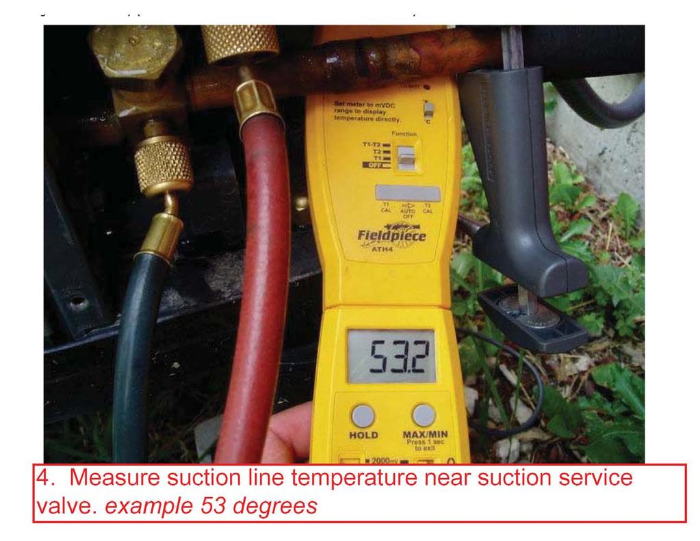
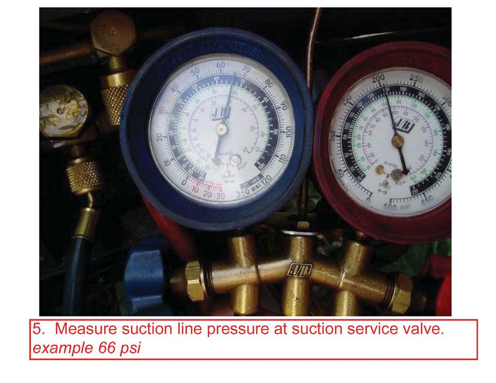
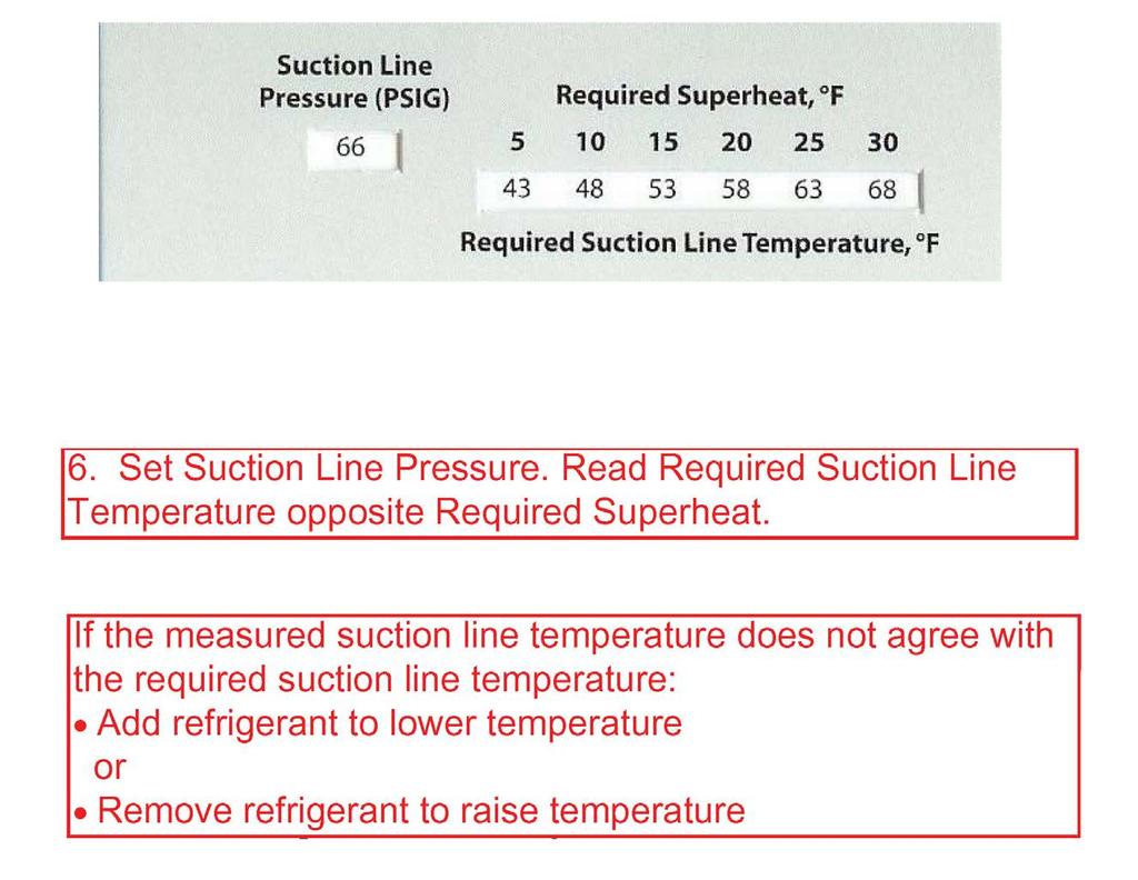
Table of Contents. Service Procedures. Service Procedures. Measuring Superheat (4) Measuring Subcooling (5) Airflow Calculation (6-8)
 Measuring Subcooling (5) Airflow Calculation (6-8)") Table of Contents Refrigeration Cycle Service Procedures Measuring Superheat (4) Measuring Subcooling (5) Airflow Calculation (6-8) Solving Problems Identifying Low System Charge (9-11) Identifying High
Table of Contents Refrigeration Cycle Service Procedures Measuring Superheat (4) Measuring Subcooling (5) Airflow Calculation (6-8) Solving Problems Identifying Low System Charge (9-11) Identifying High
SERVICING PROCEDURE R-410A LEAK TEST EVACUATION CHARGING. Bard Manufacturing Company, Inc. Bryan, Ohio Manual Page 1 of 11
 SERVICING PROCEDURE R-410A LEAK TEST EVACUATION CHARGING Bard Manufacturing Company, Inc. Bryan, Ohio 43506 Since 1914...Moving ahead, just as planned. Manual No.: 2100-479 Supersedes: NEW File: Volume
Electrical Problems. Fuse(s) blow or circuit breaker trips. Does the unit use circuit breakers or fuses? Replace with correct fuse(s)
 blow or circuit breaker trips. Does the unit use circuit breakers or fuses? Replace with correct fuse(s)") Electrical Problems Fuse(s) blow or circuit breaker trips Does the unit use circuit breakers or fuses? Fuse(s) Circuit breakers Are the fuses dual element time delay? Is the circuit breaker HACR rated?
Electrical Problems Fuse(s) blow or circuit breaker trips Does the unit use circuit breakers or fuses? Fuse(s) Circuit breakers Are the fuses dual element time delay? Is the circuit breaker HACR rated?
PROAIR Air Conditioner. CR23 Model INSTRUCTION MANUAL nvent Rev. D P/N
 PROAIR Air Conditioner CR23 Model INSTRUCTION MANUAL Rev. D P/N 89112522 TABLE OF CONTENTS Warranty and Return Policy...2 RECEIVING THE AIR CONDITIONER...3 HANDLING AND TESTING THE AIR CONDITIONER...3
INSTALLATION GUIDE. 4AC 14* ASA1 SERIES R-410a CONDENSING UNITS R-410A ATTENTION, INSTALLER! ATTENTION, USER!
 4AC 14* ASA1 SERIES R-410a CONDENSING UNITS INSTALLATION GUIDE R-410A ATTENTION, INSTALLER! After installing the system, show the user how to turn off electricity to the unit. Point out control and switch
Calhoon MEBA Engineering School. Study Guide for Proficiency Testing Refrigeration
 Calhoon MEBA Engineering School Study Guide for Proficiency Testing Refrigeration 1. To prevent an injury when working with refrigerants, what safety precautions are necessary? 2. When halogens are in
Some of these procedures need to be performed to conform to requirements of the Clean Air Act.
 Leak Detection, Recovery, Evacuation and Charging Four basic service procedures used to repair and maintain a mechanical refrigeration system are leak detection, evacuation, recovery, and refrigerant charging.
SPECTRACOOL Air Conditioner. N21 Model INSTRUCTION MANUAL nvent Rev. G P/N
 SPECTRACOOL Air Conditioner N21 Model INSTRUCTION MANUAL Rev. G P/N 89115088 TABLE OF CONTENTS WARRANTY AND RETURN POLICY...2 RECEIVING THE AIR CONDITIONER...3 HANDLING AND TESTING THE AIR CONDITIONER...3
PARALLEL RACK SYSTEM INSTALLATION & OPERATIONS MANUAL With Master Rack Compressor Sequencer
 PARALLEL RACK SYSTEM INSTALLATION & OPERATIONS MANUAL With Master Rack Compressor Sequencer 5/16 Rev. A 57-02509 2 Contents INTRODUCTION... 4 WARNING LABELS AND SAFETY INSTRUCTIONS... 5 PS SERIES PARALLEL
PROAIR Air Conditioner. CR29 Model INSTRUCTION MANUAL nvent Rev. I P/N
 PROAIR Air Conditioner CR29 Model INSTRUCTION MANUAL Rev. I P/N 89104461 TABLE OF CONTENTS Warranty and Return Policy...2 RECEIVING THE AIR CONDITIONER...3 HANDLING AND TESTING THE AIR CONDITIONER...3
Air Conditioning Operation and Troubleshooting Matt Dunham
 Air Conditioning Operation and Troubleshooting Matt Dunham Major Components (10 Minutes) Compressor heart of the system, causes refrigerant to flow by increasing the pressure of the refrigerant Metering
PROAIR Air Conditioner. CR43 Model INSTRUCTION MANUAL nvent Rev. H P/N
 PROAIR Air Conditioner CR43 Model INSTRUCTION MANUAL Rev. H P/N 10-1008-130 TABLE OF CONTENTS Warranty and Return Policy...2 RECEIVING THE AIR CONDITIONER...3 HANDLING AND TESTING THE AIR CONDITIONER...3
T-SERIES Air Conditioner. T20 Model INSTRUCTION MANUAL nvent Rev. C P/N
 T-SERIES Air Conditioner T20 Model INSTRUCTION MANUAL Rev. C P/N 89114993 TABLE OF CONTENTS Warranty and Return Policy... 2 IMPORTANT NOTICE... 2 RECEIVING THE AIR CONDITIONER... 3 HANDLING AND TESTING
SECTION 7 AIR CONDITIONING (COOLING) UNIT 41 TROUBLESHOOTING
 UNIT 41 TROUBLESHOOTING") SECTION 7 AIR CONDITIONING (COOLING) UNIT 41 TROUBLESHOOTING UNIT OBJECTIVES After studying this unit, the reader should be able to Select the correct instruments for checking an air conditioning unit
SECTION 7 AIR CONDITIONING (COOLING) UNIT 41 TROUBLESHOOTING UNIT OBJECTIVES After studying this unit, the reader should be able to Select the correct instruments for checking an air conditioning unit
Otherwise, you can continue reading the file on the following pages.
 If you d like to be able to print this file out to study off-line or use on the job, a printable version is available for an administrative fee of $3.97 USD. To download the unlocked file, click here.
CS/CD/CP AIR COOLED CONDENSING UNITS (P/N E207120C R2)
") CS*/CD*/CP* Series Air Cooled Condensing Units Operating and Installation Manual CS/CD/CP AIR COOLED CONDENSING UNITS (P/N E207120C R2) TABLE OF CONTENTS I. Receipt of Equipment 2 II. Piping...4 III. System
CS*/CD*/CP* Series Air Cooled Condensing Units Operating and Installation Manual CS/CD/CP AIR COOLED CONDENSING UNITS (P/N E207120C R2) TABLE OF CONTENTS I. Receipt of Equipment 2 II. Piping...4 III. System
T-SERIES Air Conditioner. T29 Model INSTRUCTION MANUAL nvent Rev. I P/N
 T-SERIES Air Conditioner T29 Model INSTRUCTION MANUAL Rev. I P/N 89104464 TABLE OF CONTENTS Warranty and Return Policy...2 IMPORTANT NOTICE...2 RECEIVING THE AIR CONDITIONER...3 HANDLING AND TESTING THE
T-SERIES Air Conditioner. T43 Model INSTRUCTION MANUAL nvent Rev. I P/N
 T-SERIES Air Conditioner T43 Model INSTRUCTION MANUAL Rev. I P/N 10-1008-145 TABLE OF CONTENTS Warranty and Return Policy...2 IMPORTANT NOTICE...2 RECEIVING THE AIR CONDITIONER...3 HANDLING AND TESTING
WMHP Series R410a Heat Pump INSTALLATION INSTRUCTIONS
 WMHP Series R410a Heat Pump INSTALLATION INSTRUCTIONS **WARNING TO INSTALLER, SERVICE PERSONNEL AND OWNER** Altering the product or replacing parts with non authorized factory parts voids all warranty
T-Series Air Conditioner T15 Model
 INSTRUCTION MANUAL T-Series Air Conditioner T15 Model Protecting Electronics. Exceeding Expectations. McLean Cooling Technology 11611 Business Park Blvd N Champlin, MN 55316 USA Tel 763-323-8200 Fax 763-576-3200
Instructors: Contact information. Don Reynolds Doug McGee Factory Tech Support
 Contact information Instructors: Don Reynolds 616-560-9903 Doug McGee 517-294-3932 Factory Tech Support 888-593-9988 Product Improvements for 2017 Todays Objectives Job Site Information Sheets Low Ambient
Condensing Unit Installation and Operating Instructions
 Bulletin WCU_O&I 01 June 2003 Condensing Unit Installation and Operating Instructions WCU Air Cooled Condensing Unit Table of Contents Section 1. Section 2. Section 3. Section 4. Section 5. Section 6.
GENESIS Air Conditioners. All Models INSTRUCTION MANUAL nvent Rev. K P/N
 GENESIS Air Conditioners All Models INSTRUCTION MANUAL Rev. K P/N 89104462 TABLE OF CONTENTS Warranty and Return Policy...2 RECEIVING THE AIR CONDITIONER...3 HANDLING AND TESTING THE AIR CONDITIONER...3
Installation, Operation, and Maintenance Information
 Installation, Operation, and Maintenance Information Low Velocity Unit Coolers Bulletin No. IOM 110.3 Table of Contents Inspection... 2 Installation... 2 4 General... 2 Location... 2 Drain Line... 3 Refrigerant
Trouble Shooting Guide FAA, 3-phase (D3631)
") Trouble Shooting Guide FAA, 3-phase (D3631) Trouble Shooting Guide Problem Possible Cause Possible Remedy Unit does not start Unit does not cool No power to unit, breaker tripped Low voltage tripped Loose
Trouble Shooting Guide FAA, 3-phase (D3631) Trouble Shooting Guide Problem Possible Cause Possible Remedy Unit does not start Unit does not cool No power to unit, breaker tripped Low voltage tripped Loose
T-SERIES Air Conditioner. T50 Model INSTRUCTION MANUAL nvent Rev. F P/N
 T-SERIES Air Conditioner T50 Model INSTRUCTION MANUAL Rev. F P/N 10-1008-203 TABLE OF CONTENTS Warranty and Return Policy...2 RECEIVING THE AIR CONDITIONER...3 HANDLING AND TESTING THE AIR CONDITIONER...3
AIR CONDITIONING. Carrier Corporation 2002 Cat. No
 AIR CONDITIONING Carrier Corporation 2002 Cat. No. 020-016 1. This refresher course covers topics contained in the AIR CONDITIONING specialty section of the North American Technician Excellence (NATE)
Operation Manual SCT14B and SCT18B. Inspection. 3 General Description. 3 General Requirements. 3 Standard Features.
 Spot Cooling Systems, Inc. 120 Century Drive Suite 00 Carrollton, TX 7006 00-6-776 Operation Manual SCT1B and SCT1B Warning! Improper installation, adjustment, alteration, service, or maintenance can cause
Residential Piping and Long Line Guideline
 AC / HP R-410A Refrigerant Systems Single-Stage, Two-Stage and Variable Speed Models Residential Piping and Long Line Guideline TABLE OF CONTENTS Safety Considerations... 2 Definitions... 2 Introduction...
Room Air Conditioner Service and Parts Manual
 Cool Dry Temp Mode Room Air Conditioner Service and Parts Manual F Fan Speed hr Timer 0n 0ff Money Saver Fan Only Auto Swing Power CP06 CP08 93011401_01 CONTENTS 1. PREFACE 1.1 SAFETY PRECAUTIONS...2 1.2
For an administrative fee of $9.97, you can get an un-locked, printable version of this book.
 The System Evaluation Manual and Chiller Evaluation Manual have been revised and combined into this new book; the Air Conditioning and Refrigeration System Evaluation Guide. For an administrative fee of
HSXA15 HSXB15. IMPORTANT Operating pressures of this R410A unit are higher than pressures in R22 units. Always use service equipment rated for R410A.
 Service Literature Corp. 0128 L12 Revised 10 2004 HSXB15 & HSXB15 SERIES UNITS The and HSXB15 are high efficiency residential split system condensing units, which features a scroll compressor and R410A
V-SERIES Air Conditioner. VA08 Model INSTRUCTION MANUAL nvent Rev. F P/N
 V-SERIES Air Conditioner VA08 Model INSTRUCTION MANUAL Rev. F P/N 90164959 TABLE OF CONTENTS Warranty and Return Policy...2 RECEIVING THE AIR CONDITIONER...3 HANDLING AND TESTING THE AIR CONDITIONER...3
power Describe the purpose of lockout/tag-out devices Demonstrate use of lockout/tagout
 c. All contestants are required to remain in the contest area until the contest has been torn down and excused by the Chairperson. Note: Your contest may also require a hard copy of your résumé as part
T-Series Air Conditioner T20 Model
 INSTRUCTION MANUAL T-Series Air Conditioner T20 Model Protecting Electronics. Exceeding Expectations. McLean Cooling Technology 11611 Business Park Blvd N Champlin, MN 55316 USA Tel 763-323-8200 Fax 763-576-3200
INSTALLATION AND OPERATING INSTRUCTIONS
 INSTALLATION AND OPERATING INSTRUCTIONS HIGH-EFFICIENCY CONDENSING UNITS RAWD- 6 1 2 & 7 1 2 TON RAWE - 6 1 2 & 7 1 2 TON! RECOGNIZE THIS SYMBOL AS AN INDICATION OF IMPORTANT SAFETY INFORMATION!! WARNING
CUSTOMIZED TEACHER ASSESSMENT BLUEPRINT HVAC MAINTENANCE TECHNOLOGY. Test Code: 5937 Version: 01
 CUSTOMIZED TEACHER ASSESSMENT BLUEPRINT HVAC MAINTENANCE TECHNOLOGY Test Code: 5937 Version: 01 Specific competencies and skills tested in this assessment: Introduction to HVAC Identify HVAC systems Demonstrate
Trouble Shooting Guide RAA, 1-phase (D3627)
") Trouble Shooting Guide RAA, 1-phase (D3627) Trouble Shooting Guide Problem Possible Cause Possible Remedy Unit does not start Unit does not cool No power to unit, breaker tripped Low voltage tripped Loose
Trouble Shooting Guide RAA, 1-phase (D3627) Trouble Shooting Guide Problem Possible Cause Possible Remedy Unit does not start Unit does not cool No power to unit, breaker tripped Low voltage tripped Loose
TROUBLESHOOTING GENERAL TROUBLESHOOTING PROBLEM PROBABLE CAUSE CORRECTIVE ACTION
 GENERAL TROUBLESHOOTING Compressor Conditioning system OFF Turn ON conditioning system will not run No electrical power Check fuses Wrong voltage to applied to unit Compressor internal overload tripped
Trouble Shooting Guide PAA, 1-phase (D3731)
") Trouble Shooting Guide PAA, 1-phase (D3731) Trouble Shooting Guide Problem Possible Cause Possible Remedy Unit does not start Unit does not cool No power to unit, breaker tripped Low voltage tripped Loose
Trouble Shooting Guide PAA, 1-phase (D3731) Trouble Shooting Guide Problem Possible Cause Possible Remedy Unit does not start Unit does not cool No power to unit, breaker tripped Low voltage tripped Loose
Trouble Shooting Guide PWA, 3-phase (D10571)
") Trouble Shooting Guide PWA, 3-phase (D10571) Trouble Shooting Guide Problem Possible Cause Possible Remedy Unit does not start Unit does not cool No power to unit, breaker tripped Low voltage Loose wire
Trouble Shooting Guide PWA, 3-phase (D10571) Trouble Shooting Guide Problem Possible Cause Possible Remedy Unit does not start Unit does not cool No power to unit, breaker tripped Low voltage Loose wire
EBAC MODEL CD30 INDUSTRIAL DEHUMIDIFIER OWNER S MANUAL
 EBAC MODEL CD30 INDUSTRIAL DEHUMIDIFIER OWNER S MANUAL Ebac Industrial Products 704 Middle Ground Boulevard Newport News, VA 23606 Tel: 757 873 6800 Fax: 757 873 3632 Website: www.ebacusa.com UNPACKING
EBAC MODEL CD425 ( ) INDUSTRIAL DEHUMIDIFIER OWNER S MANUAL
 INDUSTRIAL DEHUMIDIFIER OWNER S MANUAL") EBAC MODEL CD425 (1018110) INDUSTRIAL DEHUMIDIFIER OWNER S MANUAL Ebac Industrial Products 704 Middle Ground Boulevard Newport News, VA 23606 Tel: 757 873 6800 Fax: 757 873 3632 Website: www.ebacusa.com
EBAC MODEL CD425 (1018110) INDUSTRIAL DEHUMIDIFIER OWNER S MANUAL Ebac Industrial Products 704 Middle Ground Boulevard Newport News, VA 23606 Tel: 757 873 6800 Fax: 757 873 3632 Website: www.ebacusa.com
KITS COMMON TO HEATING AND COOLING EQUIPMENT 504,652M 03/04. Supersedes 503,249M
 2004 Lennox Industries Inc. Dallas, Texas KITS COMMON TO HEATING AND COOLING EQUIPMENT 504,652M 03/04 Supersedes 503,249M Litho U.S.A. COMPRESSOR REPLACEMENT KIT INSTALLATION INSTRUCTIONS FOR COMPRESSOR
Mortex INSTALLATION INSTRUCTIONS AIR CONDITIONING & HEAT PUMP INDOOR COILS
 Mortex INSTALLATION INSTRUCTIONS AIR CONDITIONING & HEAT PUMP INDOOR COILS INTRODUCTION Please note that HUD Manufactured Home Construction and Safety Standard Section 3280.714, paragraph (a) and subparagraph
XC13. IMPORTANT Operating pressures of this R 410A unit are higher than pressures in R 22 units. Always use service equipment rated for R410A.
 Service Literature Corp. 0521 L9 Revised 09 2007 XC13 SERIES UNITS XC13 The XC13 is a high efficiency residential split system condensing unit, which features a scroll compressor and R 410A refrigerant.
Data Aire, Inc. reserves the right to make design changes for the purpose of product improvement or to withdraw any design without notice.
 Data Aire, Inc. reserves the right to make design changes for the purpose of product improvement or to withdraw any design without notice. Table of Contents 1.0 Introduction 1.1 Inspection...4 1.2 Description...4
INSTALLATION INSTRUCTIONS TXV Horizontal Slab Coils WLSH
 TXV Horizontal Slab Coils WLSH These instructions must be read and understood completely before attempting installation. It is important that the Blower and Duct System be properly sized to allow the system
T-Series Air Conditioner T53 Model
 INSTRUCTION MANUAL T-Series Air Conditioner T53 Model Protecting Electronics. Exceeding Expectations. McLean Cooling Technology 11611 Business Park Blvd N Champlin, MN 55316 USA Tel 763-323-8200 Fax 763-576-3200
TECHNICAL GUIDE DESCRIPTION SPLIT-SYSTEM AIR-COOLED CONDENSING UNITS MODELS: HF-07 FEATURES B-0703
 TECHNICAL GUIDE SPLIT-SYSTEM AIR-COOLED CONDENSING UNITS MODELS: HF-07 DESCRIPTION These Sunline 2000 units are completely assembled, piped and wired at the factory to provide one-piece shipment and rigging.
EBAC MODEL CD425 ( ) INDUSTRIAL DEHUMIDIFIER OWNER S MANUAL
 INDUSTRIAL DEHUMIDIFIER OWNER S MANUAL") EBAC MODEL CD425 (1018110) INDUSTRIAL DEHUMIDIFIER OWNER S MANUAL Ebac Industrial Products, Inc. 700 Thimble Shoals Blvd, Suite 109 Newport News, VA. 23606-2575 Tel: (757) 873 6800 Fax: (757) 873 3632
EBAC MODEL CD425 (1018110) INDUSTRIAL DEHUMIDIFIER OWNER S MANUAL Ebac Industrial Products, Inc. 700 Thimble Shoals Blvd, Suite 109 Newport News, VA. 23606-2575 Tel: (757) 873 6800 Fax: (757) 873 3632
EBAC MODEL KOMPACT INDUSTRIAL DEHUMIDIFIER OWNER S MANUAL
 EBAC MODEL KOMPACT INDUSTRIAL DEHUMIDIFIER OWNER S MANUAL KOMPACT OWNERS MANUAL Page 1 of 9 INTRODUCTION Designed for a wide range of applications, the Kompact is a rugged, industrial unit, which utilizes
EBAC MODEL BD-150 ( ) INDUSTRIAL DEHUMIDIFIER OWNER S MANUAL
 INDUSTRIAL DEHUMIDIFIER OWNER S MANUAL") EBAC MODEL BD-150 (1025000) INDUSTRIAL DEHUMIDIFIER OWNER S MANUAL BD-150 OWNERS MANUAL Page 1 of 12 INTRODUCTION Designed for a wide range of applications, the BD-150 dehumidifier is a super high capacity
EBAC MODEL BD-150 (1025000) INDUSTRIAL DEHUMIDIFIER OWNER S MANUAL BD-150 OWNERS MANUAL Page 1 of 12 INTRODUCTION Designed for a wide range of applications, the BD-150 dehumidifier is a super high capacity
INSTALLATION INSTRUCTIONS
 INSTALLATION INSTRUCTIONS T CLASS TSA Series 6 to 20 Ton AIR CONDITIONERS 6 20 TONS 506147 01 06/11 Supersedes 3/11 Litho U.S.A. RETAIN THESE INSTRUCTIONS FOR FUTURE REFERENCE IMPORTANT The Clean Air Act
User s Information and Installation Instructions
 Outdoor Air Conditioner User s Information and Installation Instructions 2-Stage R-410A Split System These units have been designed and tested for capacity & efficiency in accordance with A.H.R.I. Standards.
CAUTION. Check Equipment and Job Site. Clearance Requirements. Unpack Unit
 INSTALLATION IMPORTANT: Effective January 1, 2015, all split system and packaged air conditioners must be installed pursuant to applicable regional efficiency standards issued by the Department of Energy.!
INSTALLATION INSTRUCTIONS TXV Horizontal Duct Coils EHD
 TXV Horizontal Duct s EHD These instructions must be read and understood completely before attempting installation. It is important that the Blower and Duct System be properly sized to allow the system
OPERATIONS AND MAINTENANCE MANUAL FOR THE 8-TON TURF CART ENVIRONMENTAL CONTROL UNIT (ECU) PART NUMBER
 PART NUMBER") OPERATIONS AND MAINTENANCE MANUAL FOR THE 8-TON TURF CART ENVIRONMENTAL CONTROL UNIT (ECU) PART NUMBER 2001927 Prepared by: 860 Douglas Way PO Box 530 Natural Bridge Station, VA 24579 1 1.0 SCOPE: This
OPERATIONS AND MAINTENANCE MANUAL FOR THE 8-TON TURF CART ENVIRONMENTAL CONTROL UNIT (ECU) PART NUMBER 2001927 Prepared by: 860 Douglas Way PO Box 530 Natural Bridge Station, VA 24579 1 1.0 SCOPE: This
EBAC MODEL CD30 INDUSTRIAL DEHUMIDIFIER OWNER S MANUAL
 EBAC MODEL CD30 INDUSTRIAL DEHUMIDIFIER OWNER S MANUAL Ebac Industrial Products, Inc. 700 Thimble Shoals Blvd, Suite 109 Newport News, VA. 23606-2575 Tel: (757) 873 6800 Fax: (757) 873 3632 Website www.ebacusa.com
Cased Aluminum Coils "Dedicated Upflow / Downflow" Convertible to horizontal with separately purchased kit
 18-AD32D1-3 Cased Aluminum Coils "Dedicated Upflow / Downflow" Convertible to horizontal with separately purchased kit Upflow models: 4PXCAU24BS3HAA 4PXCBU24BS3HAA 4PXCBU30BS3HAA 4PXCCU30BS3HAA 4PXCBU36BS3HAA
TSA WARNING. Service Literature TSA SERIES UNITS. 6, 7.5, 10, 12.5, 15 & 20 ton
 Service Literature Corp. 0903 L1 Revised: March 2011 TSA SERIES UNITS TSA 6, 7.5, 10, 12.5, 15 & 20 ton The TSA units are designed for light commercial applications, with a remotely located blower coil
Beverage Air IMPORTANT
 Beverage Air IMPORTANT INFORMATION FOR CT96 MODEL This cooler has passed the QUALITY CONTROL INSPECTION And meets the high standards for Beverage-Air Refrigeration products IMPORTANT PLEASE RETAIN FOR
Installation Instructions
 24AHA4 Performance Series Air Conditioner with Puron Refrigerant 1-1/2 to 5 Nominal Tons Installation Instructions Fig. 1-24AHA4 A07532 SAFETY CONSIDERATIONS Improper installation, adjustment, alteration,
HS25 SERVICE UNIT INFORMATION
 SERVICE UNIT INFORMATION HS25 Corp. 9327-L3 Litho U.S.A. HS25 SERIES UNITS The HS25 is a high efficiency residential split system condensing unit which features a scroll compressor. It operates much like
13ACX. IMPORTANT Operating pressures of this R 410A unit are higher than pressures in R 22 units. Always use service equipment rated for R 410A.
 Service Literature Corp. 0612 L2 Revised 07 2006 13ACX SERIES UNITS 13ACX The 13ACX is a high efficiency residential split system condensing unit, which features a scroll compressor and designed for R
Corp L9 Revised HS27 SERIES UNITS SPECIFICATIONS. Model No. HS HS HS HS27-042
 Service Literature Corp. 9619 L9 Revised 08 2004 HS27 SERIES UNITS HS27 The HS27 is a 14 SEER high efficiency residential split system condensing unit which features a scroll compressor. It operates much
MYSTICOOL Max Valve System with Xstream and A.R.M.E.D. Technology Service & Installation Instructions Page 1
 Page 1 WHY should I install the MYSTICOOL Max Valve System? XDX is more efficient, saving on power consumption. Use of XDX system decreases defrost cycles. XDX maintains more consistent product temperatures,
13ACX. IMPORTANT Operating pressures of this R 410A unit are higher than pressures in R 22 units. Always use service equipment rated for R 410A.
 Service Literature Corp. 0612 L2 Revised 06 2007 13ACX SERIES UNITS 13ACX The 13ACX is a high efficiency residential split system condensing unit, which features a scroll compressor and designed for R
XC16. IMPORTANT Operating pressures of this R 410A unit are higher than pressures in R 22 units. Always use service equipment rated for R410A.
 Service Literature Corp. 0625 L5 Revised 07 2006 XC16 SERIES UNITS XC16 The XC16 is a high efficiency residential split system condensing unit, which features a two speed scroll compressor and R 410A refrigerant.
Full Range Systems. Mokon Troubleshooting Guide Model 311. Process/Water Loop. Problem Possible Cause Corrective Measure. Process pump will not start
 Mokon Troubleshooting Guide Model 311 Process pump will not start Process pump shuts down during operation Pump seal leak Tank overflows or will not fill on systems with autofill option (water makeup valve)
EBAC MODEL CD60 INDUSTRIAL DEHUMIDIFIER OWNER S MANUAL
 EBAC MODEL CD60 INDUSTRIAL DEHUMIDIFIER OWNER S MANUAL CD60 OWNERS MANUAL Page 1 of 9 INTRODUCTION Designed for a wide range of applications, the CD60 dehumidifier is a rugged, industrial unit which utilizes
SECTION 8 AIR SOURCE HEAT PUMPS UNIT 43 AIR SOURCE HEAT PUMPS
 SECTION 8 AIR SOURCE HEAT PUMPS UNIT 43 AIR SOURCE HEAT PUMPS UNIT OBJECTIVES After studying this unit, the reader should be able to Describe the operation of reverse-cycle refrigeration (heat pumps) Explain
Air-Cooled Split-System Condensing Units for Rooftop Systems and Air Handlers Models RCS 10E to 20E 10, 12.5, 15 & 20 Tons
 Installation and Maintenance Manual IM 910 Group: Applied Systems Air-Cooled Split-System Condensing Units for Rooftop Systems and Air Handlers Models RCS 10E to 20E 10, 12.5, 15 & 20 Tons Part Number:
XSTREAM Valve System With A.R.M.E.D. Technology Service & Installation Instructions Page 1
 Page 1 WHY should I install the XSTREAM Valve System? XDX is more efficient, saving on power consumption. Use of XDX system decreases defrost cycles. XDX maintains more consistent product temperatures,
UNDERCOUNTER LABORATORY REFRIGERATORS and FREEZERS Installation, Operation and Maintenance Instructions
 UNDERCOUNTER LABORATORY REFRIGERATORS and FREEZERS Installation, Operation and Maintenance Instructions INSPECTION When the equipment is received, all items should be carefully checked against the bill
Refrigerant Recovery Machine. Model No Operating Manual
 Refrigerant Recovery Machine Model No. 25700 Operating Manual Safety Precautions WARNING : TO PREVENT PERSONAL INJURY AND / OR EQUIPMENT DAMAGE, CAUTION - Risk of injury. This equipment should only be
CENTRAL, SPLIT SYSTEM REFRIGERATED AIR-CONDITIONING INSPECTION INTERIOR
 Consulting, Resource, Education, Training, and Support Services for Home Inspectors A candle loses no light when it lights another candle. CENTRAL, SPLIT SYSTEM REFRIGERATED AIR-CONDITIONING INSPECTION
Aspects of the. Following these key guidelines during a compressor changeout can ensure a successful, more efficient replacement.
 Aspects of the Compressor Retrofit Following these key guidelines during a compressor changeout can ensure a successful, more efficient replacement. B y J o h n P r a l l a n d D e n n y M a r t i n All
EBAC MODEL WM150 INDUSTRIAL DEHUMIDIFIER OWNER S MANUAL
 EBAC MODEL WM150 INDUSTRIAL DEHUMIDIFIER OWNER S MANUAL WM150 OWNERS MANUAL Page 1 of 9 INTRODUCTION Designed for a wide range of applications, the WM150 is a rugged, industrial unit, which utilizes an
INSTALLATION AND MAINTENANCE INSTRUCTIONS 4SCU16LT Series Split System Air Conditioner WARNING
 INSTALLATION AND MAINTENANCE INSTRUCTIONS 4SCU16LT Series Split System Air Conditioner WARNING The equipment covered in this manual is to be installed by trained and experienced service and installation
Installation Instructions
 PREFERREDT SERIES AIR CONDITIONER WITH PURONR REFRIGERANT 1-1/2 TO 5 NOMINAL TONS Installation Instructions Fig. 1 --- 538A NOTE: Read the entire instruction manual before starting the installation. TABLE
Installation Instructions
 Performance Series Heat Pumps with PURONr Refrigerant 1 --- 1/2 to 5 Nominal Tons Installation Instructions Fig. 1 --- A07532 NOTE: Read the entire instruction manual before starting the installation.
Preventative Maintenance Tables
 Preventative Maintenance Tables Table of Contents I. Table : Gas Fired Domestic Hot Water Heater II. III. IV. Table : Circulating Pump Table : Convectors Table 4: Grille and Diffusors V. Table 5: Unit
Service Step by Step Trouble-Shooting Check-List
 WARNING: Only Data Aire trained technician or experience technicians should be working on Data Aire Equipment. Protect yourself at all times and work safe. Date: Dates at the job site: From: to Job#: Serial#:
Condensing Unit Installation and Operating Instructions
 Bulletin ACU_O&I 02 August 2016 Condensing Unit Installation and Operating Instructions ACU Air Cooled Condensers Table of Contents Section 1. General Information... 2 Section 2. Refrigeration Piping...
CHILLER. Operator s & Installation Manual
 CHILLER MODELS: CH1001-A Operator s & Installation Manual Release Date: August 9, 2002 Publication Number: 620914301 Revision Date: May 6, 2010 Revision: E Visit the IMI Cornelius web site at www.cornelius.com
HPXA15 HPXB15 WARNING
 Service Literature Corp. 0202 L1 Revised 09 2004 HPXA15 HPXB15 HPXA15 and HPXB15 SERIES UNITS The HPXA15 and HPXB15 are high efficiency residential split system heat pump units, which features a scroll
Warm Case Troubleshooting Guide 9/18/2014
 Introduction Warm cases can be caused by various problems which require thorough troubleshooting. Begin the investigation with questions to store personnel asking for information such as when the last
ENVIRONMENTAL CONTROL UNIT (ECU) PART NUMBER OPERATIONS AND MAINTENANCE MANUAL
 PART NUMBER OPERATIONS AND MAINTENANCE MANUAL") ENVIRONMENTAL CONTROL UNIT (ECU) PART NUMBER 2001829 OPERATIONS AND MAINTENANCE MANUAL Prepared by: 860 Douglas Way PO Box 530 Natural Bridge Station, VA 24579 1.0 SCOPE: This Operations and Maintenance
ENVIRONMENTAL CONTROL UNIT (ECU) PART NUMBER 2001829 OPERATIONS AND MAINTENANCE MANUAL Prepared by: 860 Douglas Way PO Box 530 Natural Bridge Station, VA 24579 1.0 SCOPE: This Operations and Maintenance
Experienced Worker Assessment Blueprint HVAC - Heating, Ventilation and Air Conditioning
 Blueprint HVAC - Heating, Ventilation and Air Conditioning Test Code: 0144 / Version: 02 Specific Competencies and Skills Tested in this Assessment: Electricity Demonstrate understanding of basic AC/DC
Installation Instructions
 25HHA4 Performance Series Heat Pump with Puron Refrigerant 1-1/2 to 5 Nominal Tons Installation Instructions Fig. 1-25HHA4 A07532 SAFETY CONSIDERATIONS Improper installation, adjustment, alteration, service,
Room Air Conditioner CP06 & CP08. Chill 115 Volts. Service & Parts Manual THE EXPERTS IN ROOM AIR CONDITIONING _02
 Room Air Conditioner Service & Parts Manual 2014-2015 CP06 & CP08 Chill 115 Volts THE EXPERTS IN ROOM AIR CONDITIONING 93011401_02 CONTENTS 1. PREFACE 1.1 SAFETY PRECAUTIONS...2 1.2 INSULATION RESISTANCE
HP13 WARNING WARNING. Service Literature HP13 SERIES UNITS
 Service Literature Corp. 0610 L1 Revised 07 2006 HP13 SERIES UNITS HP13 The HP13 is a high efficiency residential split system heat pump unit, which features a scroll compressor. HP13 units are available
POLAR TEMP FARM MORTALITY UNIT OPERATION MANUAL
 POLAR TEMP FARM MORTALITY UNIT OPERATION MANUAL www.polartemp.com TABLE OF CONTENT Disclaimer.......................................... Page 3 Inspection, unpacking and FMU setup.................. Page
Split Floor-Mounted Cooling System Operation Care Installation Manual
 Split Floor-Mounted Cooling System Operation Care Installation Manual CT14TSA CT13TSA CT12TSA CT34TSA CT1TSA CT14TSA-LA CT13TSA-LA CT12TSA-LA CT34TSA-LA CT1TSA-LA www.apexwinecellars.com Apex 17631 S Susana
Component. Maintenance. Manual Z SERIES. Evaporator Assembly
 Component Maintenance Manual with Illustrated Parts List for Z21-701-SERIES Evaporator Assembly 1 of 16 Record of Revision REVISION ISSUE POSTED NO: DATE DATE INSERTED BY: 2 of 16 List of Effective Pages
RecoverX Oil-Filled Hermetic Refrigerant Recovery System. Operation and Maintenance Manual
 RecoverX Oil-Filled Hermetic Refrigerant Recovery System Operation and Maintenance Manual Table of Contents Page General Safety Instructions 2-3 System Overview 3 Operating Guide 4 Restart Procedure 4
Operation and Maintenance Manual
 Warranty Information Ritchie Engineering guarantees YELLOW JACKET products to be free of defective material and workmanship which could affect the life of the product when used for the purpose for which
Hoshizaki America, Inc.
 Hoshizaki America, Inc. Commercial Refrigerators & Freezers Models RR28A RR55A RF28A RF55A A Superior Degree of Reliability SERVICE MANUAL www.hoshizaki.com Number: 73139 Issued: 8-31-2006 IMPORTANT Only
User s Information and Installation Instructions
 Outdoor Air Conditioner User s Information and Installation Instructions 10 SEER Standard Efficiency Split System These units have been designed and tested for capacity and efficiency in accordance with