Smart Smart IR. Service instruction SALES DATE MANUFACTURED ON (DATE): APPROVAL MARK SOLD. model (check applicable) is recognized as serviceable
|
|
|
- Erika Hensley
- 5 years ago
- Views:
Transcription
: SOLD APPROVAL MARK")
1 Smart Smart IR model (check applicable) is recognized as serviceable Service instruction SALES DATE MANUFACTURED ON (DATE): SOLD APPROVAL MARK SMART-EN-04
2 BLAUBERG Company is happy to offer your attention a new generation product, the BLAUBERG Smart fan. The solid team of high-qualified professionals with many years of working experience, technological innovations in design and production, high-quality components and materials from the top worldwide producers have become the precondition for the best fan in its class. BLAUBERG Smart fan is the combination of design, high performance and silence operation multiplied by intelligence. While you enjoy your rest, the BLAUBERG Smart guards your comfort. It is enough to connect it to power mains to have the ideal microclimate in your bathroom automatically maintained. INTRODUCTION The present service instruction contains a technical description, technical data sheets, operation and mounting guidelines, safety precautions and warnings for safe and correct operation of the fan BLAUBERG Smart. USE BLAUBERG Smart fan is designed for ventilation of humid residential and public premises heated during winter season. The fan design is regularly improved, so some models can slightly differ from those ones described in this service instruction. COMPLETE SET The complete set includes: fan - 1 item; connecting piece with a back valve Ø 100 mm - 1 item; connecting piece with a back valve Ø 125 mm - 1 item; remote controller - 1 item; screws and dowels - 4 items; service instruction; packing box. BASIC CHARACTERISTICS The fan designations, parameters, outer view, overall and connecting dimensions are shown in tables 1, 2,, 4 and in fig. 1, 2. Voltage [V] Frequency [Hz] Max. power [W] Current [A] RPM [min-1] Max. air capacity [m /h] Ingress Protection Rating Weight [kg] Table ,8 0, IP 44 0,5
3 Connecting piece diameter Speed mode Max. air capacity [m /h] Noise level, m [dba] 24 Hours 17 Quiet Maximal Hours Quiet 8 21 Maximal 1 2 Functions Air capacity, factory settings [m /h] Control range [m /h] Table 2 Type Humidity control 24 Hours Turn-on delay timer Turn-off delay timer Speed adjustment Interval ventilation External switch Pause Motion sensor SMART SMART IR The fan has four basic modes and one extra mode: Table SLEEP - in this mode the fan does not move and it is ready to accept a signal from the sensors or from the external switch. 24 Hours - the fan runs permanently with low speed and provides minimum air exchange in the room. After humidity changes the fan turns to MAXIMAL mode (by default) or QUIET mode. After the motion sensor detects some movement in the room or after signal from the external sensor the fan turns to QUIET mode. QUIET - optimal operation mode of the fan that ensures sufficient air capacity and low noise level. This mode is turned on after activation of the motion sensor, closing of the external switch or humidity level increase. For the humidity sensor this mode may be activated from the fan menu. MAXIMAL - operation mode with maximum air capacity. It is turned on after humidity increase. This mode is activated for the humidity sensor by default. INTERVAL VENTILATION - extra mode. After 15 hours standstill the fan is turned on to ventilate the room with air capacity 8/72m /h (Ø125/Ø100) for 2 hours. If any sensor or the external switch is activated during interval ventilation mode, the fan will switch to the respective mode depending on the activated device.
4 Model a b Dimensions [mm] c d e SMART/ SMART IR 155, / Table OPERATION RULES The fan is rated for connection to single-phase ac V / Hz power supply and is designed for continuous operation always connected to power mains. The fan is rated for operation at ambient temperature from 1 C up to 45 C. The fan does not require grounding. The fans do not cause interference with radio-, TV- or video- equipment. Service life is not less than 5 years. SAFETY RULES All operations related to the fan electrical connections, servicing and repair works are allowed only after the fan disconnection from power mains. All mounting and servicing operations are allowed for duly qualified electricians with valid electrical work permit for electric operations at the units up to 1000 V after careful study of the present user's manual. 4
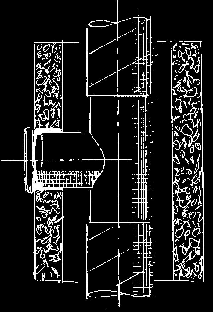
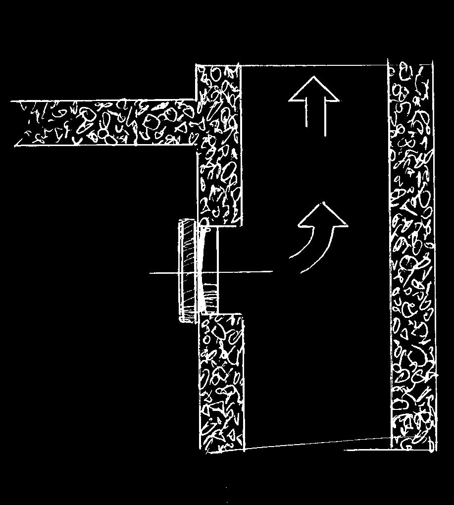
5 The single-phase power grid must comply with the acting local electrical norms and standards. The fixed electrical wiring must be equipped with an automatic circuit breaker that is used for connection of the fan to power mains with gap on all poles at least mm. Make sure the impeller and the casing are not damaged before starting installation. The casing internals must be free of any foreign objects which can damage the impeller blades. Misuse of the product or any unauthorized modification are not allowed. The product is not allowed for use by children and persons with reduced physical, mental or sensory capacities, without proper practical experience or expertise, unless they are controlled or instructed on the product operation by the person(s) responsible for their safety. Supervise the children and do not let them play with the product. Take steps to prevent ingress of smoke, carbon monoxide and other combustion products into the room through open chimney flues or other fire-protection devices. Sufficient air supply must be provided for proper combustion and exhaust of gases through the chimney of fuel burning equipment to prevent back drafting. The maximum permitted pressure difference per living units is 4 Pa. Operating medium must not contain any dust or other solid impurities, sticky substances or fibrous materials. The fan is not rated for operation in a media that contains hazardous or explosive materials and vapours, i.e. spirits, gasoline, insecticides, etc. Do not close or block the fan intake or exhaust vent not to disturb the natural air passage. Do not sit on the fan and do not put objects on the fan. Follow the guidelines of this service instructions to ensure durable operation of the product. MOUNTING AND SETUP Disconnect the fan from power mains prior to mounting and wireworks! The fan is designed for wall mounting inside a round Ø 100 or 125 mm air duct or installation a the ventilation shaft. Use a replaceable connecting piece of required diameter to facilitate mounting. To prevent air backdraught from the air duct press the back valve on a replaceable connecting piece until click, fig. 7. 5
6
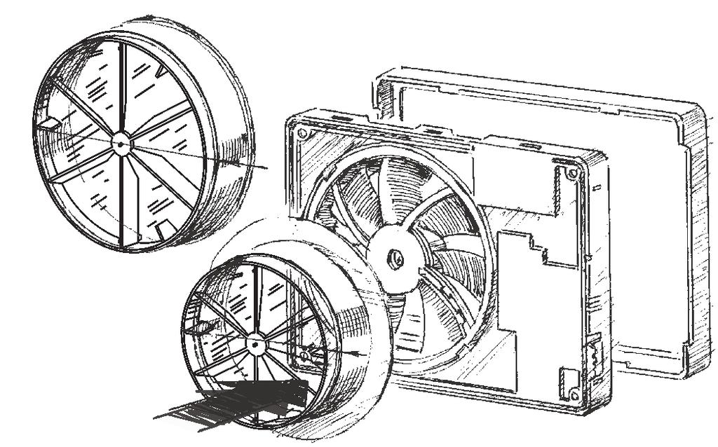
7 The fan is equipped with a removable grille. To release the grille from the face cover press the latches gently. During mounting of the grille on the face cover back match the latches and corresponding slots in the cover and insert to click. The arrow on the grille back side must be directed to the shorter side close to the hole. 8 9 The fan casing has three round lowered tabs for cable entry. Cut out a hole at the most suitable place with a knife. 10 7
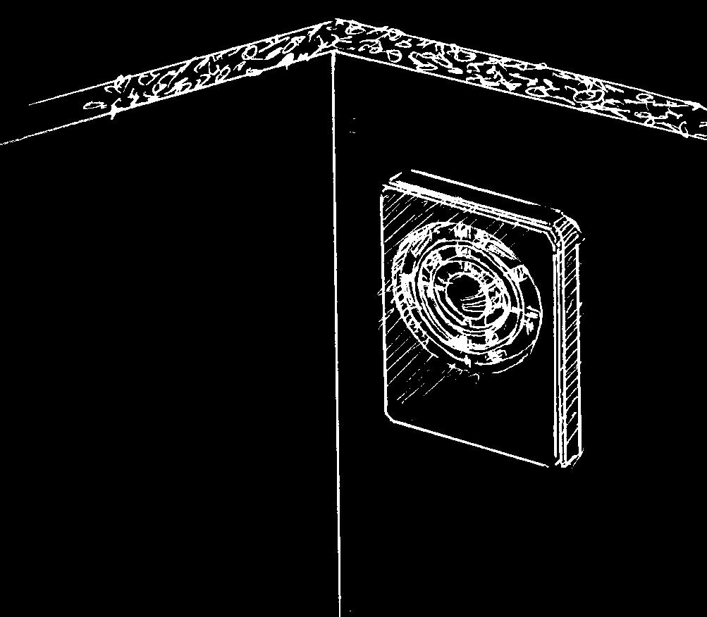
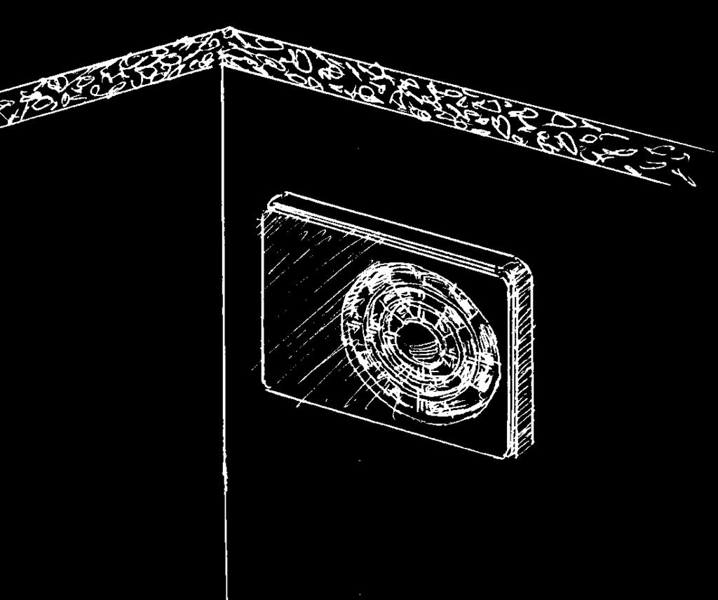
8 FAN MOUNTING
9
10 The fan is rated for connection to V / Hz power mains. Follow one of four available wiring diagrams to connect the fan to power mains. The model SMART IR is fitted with extra terminal LI that is used for connection of the light lamp up to 200 W/20 W or 100 W/10 V. The fan connected according to this wiring diagram will be switched on receipt of the signal from the motion sensor. Wiring diagram 1 Wiring diagram 2 Wiring diagram Wiring diagram 4 Wiring diagram 1 Automatic humidity and movement control (SMART IR). The contacts L and N are connected to live and zero of power mains. The fan is in SLEEP mode (does not run). If 24 HOURS mode is activated, the fan switches to permanent low speed mode to provide minimum round-the-clock ventilation. After receipt of a signal from the motion sensor (for SMART IR model only) the fan turns to QUIET mode. Some time after no movement is detected any more the fan reverts to the previous mode. After humidity level increase the fan is turned to MAXIMAL mode (by default) or QUIET mode. Some time after humidity drop the fan reverts to the previous mode. 10
11 Wiring diagram 2 Permanent fan operation with automatic humidity and movement control (SMART IR). The contacts L and N are connected to live and zero of power mains and the contacts L and LT are bridged with a jumper. The fan runs permanently at low speed. 24 HOURS mode is not available. After receipt of a signal from the motion sensor (for SMART IR model only) the fan turns to QUIET mode. Some time after no movement is detected any more the fan reverts to the previous mode. After humidity level increase the fan turns to MAXIMAL mode (by default) or QUIET mode. Some time following the humidity drop the fan reverts to the previous mode. Wiring diagram Automatic humidity and movement control (SMART IR), timer and external switch. The contacts L and N are connected to live and zero of power mains and the contact LT is connected to live through an external switch, for example, the lighting switch. The fan is in SLEEP mode (does not run). If 24 HOURS mode is activated the fan switches to permanent low speed mode to provide minimum round-the-clock ventilation. After receipt of a signal from the motion sensor (for SMART IR model only) the fan is turned to QUIET mode. Some time after no movement is detected any more the fan reverts to the previous mode. After closing of the external sensor the fan is turned to QUIET mode. Some time after the external switch is opened the fan reverts to the previous mode. After humidity increase the fan turns to MAXIMAL (by default) or QUIET mode. Some time after humidity drop the fan reverts to the previous mode. Wiring diagram 4 Automatic humidity and movement control (SMART IR), timer and momentary switch. The contacts L and N are connected to live and zero of power mains and the contact LT is connected to live through an external momentary switch, for example, door open sensor. The fan is in SLEEP mode by default (does not run). If 24 HOURS mode is activated the fan switches to permanent low speed mode to provide minimum round-the-clock ventilation. After receipt of a signal from the motion sensor (for SMART IR model only) the fan is turned to QUIET mode. Some time after no movement is detected any more the fan reverts to the previous mode. After short-term activation of the momentary switch the fan is turned to QUIET mode and operates in this mode for the time set by the turn-off timer. After that the timer reverts to the previous mode. After humidity increase the fan turns to MAXIMAL (by default) or QUIET mode. Some time after humidity drop the fan reverts to the previous mode. 11
12 OPERATING PATTERN - DIAGRAM 1 SLEEP Mode (fan does not run) or 24 HOURS mode Fan runs with air flow 40/ m /h Humidity changes Motion sensor is activated Turn-on delay timer starts (0-2-5 min) Turn-on delay timer starts (0-2-5 min) MAXIMAL (QUIET) mode is turned on Fan operates in QUIET mode Humidity stabilization No movement is detected Humidity timer starts ( min) Turn-off delay timer starts ( min) Signal to LI terminal (light is on) Signal to LI terminal (light is off) 12
13 OPERATING PATTERN - DIAGRAM 2 Fan runs with air flow 8/72 m /h (MAXIMAL) 40/ m /h (QUIET) Humidity changes Motion sensor is activated Turn-on delay timer starts (0-2-5 min) Turn-on delay timer starts (0-2-5 min) MAXIMAL (QUIET) mode is turned on Fan operates in QUIET mode Humidity stabilization No movement is detected Humidity timer starts ( min) Turn-off delay timer starts ( min) Signal to LI terminal (light is on) Signal to LI terminal (light is off) 1
14 OPERATING PATTERN - DIAGRAM Humidity changes Turn-on delay timer starts (0-2-5 min) MAXIMAL (QUIET) mode is turned on Humidity stabilization Humidity timer starts ( min) SLEEP Mode (fan does not run) or 24 HOURS mode Fan runs with air flow 40/ m /h Switch is closed Motion sensor is activated Turn-on delay timer starts (0-2-5 min) Fan operates in QUIET mode Switch is opened No movement is detected Turn-off delay timer starts ( min) Signal to LI terminal (light is on) Switch is opened Signal to LI terminal (light is off) 14
15 OPERATING PATTERN - DIAGRAM 4 Humidity changes Turn-on delay timer starts (0-2-5 min) MAXIMAL (QUIET) mode is turned on Humidity stabilization Humidity timer starts ( min) SLEEP Mode (fan does not run) or 24 HOURS mode Fan runs with air flow 40/ m /h Switch is closed Motion sensor is activated Turn-on delay timer starts (0-2-5 min) Fan operates in QUIET mode No movement is detected Turn-off delay timer starts ( min) Signal to LI terminal (light is on) Signal to LI terminal (light is off) 15
16 FAN ADJUSTMENT The fan is adjusted at the factory and is ready for operation. It is a fully serviceable product that does not require compulsory adjustments. If you want to adjust the fan according to your needs, please follow the instruction below. In case of need you may reset to the factory settings. FACTORY SETTINGS Table 5 SLEEP mode air capacity, m /h 24 HOURS mode air capacity (Ø125 / Ø100), m /h QUIET mode air capacity (Ø125 / Ø100), m /h MAXIMAL mode air capacity (Ø125 / Ø100), m /h humidity extraction mode turn-on delay timer settings, min turn-off delay timer settings, min humidity timer settings, min Motion sensor (for model SMART IR only) 24 HOURS mode 0 40/ 8/72 97/82 MAXIMAL off off CONTROL PANEL SMART SMART IR Extra button to control the fan Turning 24 HOURS mode on/off Adjustment of the turn-on delay timer Turning motion sensor on/off Speed adjustment for the modes QUIET and MAXIMAL Adjustment of the turn-on/ turn-off delay timer Adjustment of the humidity extraction mode 2 16
17 REMOTE CONTROLLER For your maximum comfort we equipped the fan with a remote infra-red remote controller. You may use the remote controller to adjust the fan. The fan sends a sound signal each time after it receipt a signal from the remote controller to confirm setting adjustments. If the fan sends no sound signal, press the button once again. If necessary decrease the distance to the fan. ATTENTION! The maximum sensitive range of the remote controller is m. For easy control please direct the remote controller straight to the fan. The temperature adjustment buttons " (applicable for the SMART THERMO model). " on the remote controller are not activated Button Operation description Turning the fan on/off Quiet humidity extraction mode selection and Quiet speed adjustment Maximal humidity extraction mode selection and Maximal speed adjustment Turning the motion sensor on / off (Only for the model SMART IR) Turning Pause mode on/off Turning 24 HOURS mode on/off Adjustment of the turn-on delay timer for 0, 2 and 5 minutes respectively Adjustment of the turn-off delay timer for 5, 15 and 0 minutes respectively Table
18 FAN MODE INDICATION motion sensor / external switch is activated Green Green SLEEP mode 2 Sek. 24 HOURS mode Red Humidity extraction mode 2 Sek. Red QUIET MODE SPEED ADJUSTMENT By default this speed provides air capacity 8/72 m/h (Ø125 / Ø100). Speed adjustment: On the control panel: press the button "" to increase or the button "-" to decrease the fan speed. On the remote controller: press the " " button to increase or the " " button to decrease the fan speed. The buttons are located on the right side of the button QUIET. To display the current air capacity press the button "" or "-" once. MAXIMAL MODE SPEED ADJUSTMENT By default this speed provides an air capacity of 97/82 m/h (Ø125 / Ø100). Speed adjustment: On the control panel: press and hold the button "MODE" then press the button "" to increase or the button "-" to decrease the fan speed. On the remote controller: press the button " " to Turn-on delay timer 8/72 increase or the button " " to decrease the fan speed. The buttons are located on the right side of the button 1/106 MAXIMAL. To display the current air capacity, press and hold the button 77/66 127/102 72/61 10/86 109/90 115/94 121/98 "MODE", then press the button "" to increase or the button "-" to decrease the air capacity. 18 Red Interval ventilation mode 1 Sek. Green Red 0.5 Sek. 57/49 62/5 67/57 52/45 97/82 48/41 87/75 92/79 44/7 40/ air capacity, m /h 8/72 air capacity, m /h
19 SELECTION OF HUMIDITY EXTRACTION MODE If humidity changes the fan is turned on to higher speed to remove excessive humidity. After humidity stabilization in the room the humidity timer is activated and the fan runs within time period set by the humidity extraction timer and then reverts to the previous mode. To select the humidity extraction mode, press the "HUMIDITY MODE" button on the control panel or the "QUIET and "MAXIMAL" buttons on the remote controller. To display the current mode, press the "HUMIDITY MODE" button once. Note: Stabilization of the humidity is understood as change of humidity level not more than by % within 5 minutes. MAXIMAL Humidity-response mode with the impeller speed that ensures the best air capacity. This mode is recommended for the bathrooms above 6 m2. QUIET Humidity-response mode with the impeller speed providing silent fan operation. This mode is recommended for small bathrooms. 28 HUMIDITY TIMER ADJUSTMENT After humidity stabilization the fan continues operating some time at higher speed for total humidity removal. This timer is adjustable for 0, 45 or 60 minutes. The default time is 0 minutes. If humidity changes less by 20% for 10 minutes the timers setting automatically drops to 15 min. 0 min 45 min 60 min Humidity extraction timer adjustment: On the control panel: press and hold the button "MODE", then press the button "TIMER". On the remote controller is this adjustment not available. To display the current humidity extraction timer settings, press and hole the button "MODE" and then press the button "TIMER" once
20 ADJUSTMENT OF TURN-OFF DELAY TIMER After activation of the motion sensor or external switch the fan operates some time period and then reverts to the previous mode. Adjustment of the turn-off delay timer: On the control panel: press the button "TIMER" and adjust the turn-off delay time for 5, 15 or 0 minutes. On the remote controller: press the buttons "5", "15" or "0" minutes respectively. To display the current turn-off delay timer settings, press the button "TIMER" on the control panel once. 5 min 15 min 0 min 0 ADJUSTMENT OF TURN-ON DELAY TIMER If you have to use your bathroom often and shortly, you can adjust the turn-on delay timer to avoid the fan unnecessary switching. After humidity increases or after signal from the external switch/motion sensor, the fan switches to higher speed in some time period (0, 2 or 5 min). Adjustment of the turn-on delay timer: On the control panel: press and hold the button "SWITCH DELAY" and synchronously press the button "TIMER". On the remote controller: press the buttons "0", "2", "5" respectively. To display the current turn-on delay timer settings, press and hold the button SWITCH DELAY" and then press the button "TIMER" on the control panel once. 0 min 2 min 5 min 1 ACTIVATION OF MOTION SENSOR (SMART IR) To turn the motion sensor on, press the "On/Off move" button on the control panel or the " button on the remote controller. The indicator light "STATUS" under this button confirms that the motion sensor is turned on. To display the current motion sensor settings, press the button "On/Off move" on the control panel once. 2 20
21 ACTIVATION OF MODE 24 HOURS In this mode the fan runs with minimum air capacity before the humidity sensor, motion sensor or external switch is activated. Press the "24 HOURS" button on the control panel or the " button on the remote controller to activate this function. The green indicator light under this button on the control panel confirms that this mode is activated. Press the button "24 HOURS" once again to deactivate "24 HOURS" mode. This function is not available for the wiring diagram 2. PAUSE Press the button "PAUSE" on the remote controller if you want to stop the fan for 45 minutes. After the timer countdown the fan reverts to the previous operation mode. Press the button "PAUSE" once again to cancel the pause mode. This function is controllable only from the remote controller. ACTIVATION / DEACTIVATION OF THE FAN Press the button " on the remote controller to deactivate the fan. The light on the fan goes off and the fan does not response to any external factors as humidity change, motion or closing of the external switch. The interval ventilation function remains active - in 15 hours the fan is switched to 2 hours to ventilate the premise. This function is controllable only from the remote controller. RESET TO FACTORY SETTINGS A built-in manual power slide switch is located in the fan side panel. Turn the fan off with the slide switch, press and keep the button "MODE" on the control panel and then turn the fan on again with the slide switch. After the fan is turned on, keep the button "MODE" about 5 seconds until the light indicator stops blinking green. Push 4 21
22 MAINTENANCE Any servicing and maintenance operations of the fan are allowed after it is disconnected from power mains only. Maintenance means regular cleaning of the fan surfaces from dirt and dust. To clean the fan, wipe its surfaces with a cloth wetted in a mild soap solution, then wipe the surfaces dry. Avoid water dripping on the motor and circuit board! The battery of the remote controller, model CR2025 V, must be regularly replaced
23 STORAGE AND TRANSPORTATION RULES Transport the product in the manufacturer's original package. Transportation is allowed by any transportation vehicle provided that the product is protected against weather influence. Store the delivered product in the manufacturer's original packing box in a dry ventilated premise with the ambient temperature from 5 C up to 40 C and relative humidity less than 80%. The storage environment must be free of dust, acid or alkali vapours to prevent corrosion. The fan complies with the requirements according to the EU norms and directives, to the relevant EU-Low Voltage Equipment Directives, EU-Directives on Electromagnetic Compatibility. We hereby declare that the following product complies with the essential protection requirements of Electromagnetic Council Directive 2004/108/EC, 89/6/EEC and Low Voltage Directive 2006/95/EC, 7/2/EEC and CE-marking Directive 9/68/EEC on the approximation of the laws of the Member States relating to electromagnetic compatibility. This certificate is issued following test carried out on samples of the product referred to above. Assessment of compliance of the product with the requirements relating to electromagnetic compatibility was based on the following standards. Protection degree index according to IP rating against access to hazardous parts and water ingress - IP 44. The manufacturer hereby ensures the steady fan operation within 5 years since the date of sale through the retail distribution network provided that transportation, storage, mounting and operation instructions are observed. In case of failure due to manufacturing defects the during warranty period due to manufacturing defects, contact the seller for the product replacement. In case of no proof of sales date the warranty period is calculated from the production date. Replacements are offered by the Seller. MANUFACTURER'S WARRANTY WARNING The manufacturer is not responsible for any mechanical or physical damages resulting from the manual requirements violence, the unit misuse or gross mechanical effect. Follow the guidelines set forth in the user's manual for proper functioning of the fan. 2
INTELLIGENT AXIAL FAN user's manual
 ACCEPTANCE CERTIFICATE The fan is duly recognized as serviceable. ifan Approval mark Manufactured on (date) Sold (name and stamp of the trade company) INTELLIGENT AXIAL FAN user's manual model VENTS ifan
Wind. Service instruction
 Wind Service instruction E BAUBERG Company is happy to offer your attention the window axial Blauberg Wind fan. The solid team of high-qualified professionals with many years of working experience, technological
Aero. Service Instructions
 Aero ervice Instructions E BAUBERG Company is happy to offer your attention a new generation product, the BAUBERG Aero fan. The solid team of highqualified professionals with many years of working experience,
Turbo. Service Instructions
 Turbo Service Instructions E BAUBERG Company is happy to offer your attention a new highquality inline mixed-flow Blauberg Turbo fan. The solid team of highqualified professionals with many years of working
Calm. Service Instructions
 Calm E ervice Instructions BAUBERG VETIATORE GmbH is happy to offer you a new generation product, the BAUBERG Calm fan. The solid team of high-qualified professionals with many years of working experience,
AXIS-QA G TUBO-M/MZ AXIAL FANS. Axis / Tubo OPERATION MANUAL
 TUBO-M/MZ AXIS-QA AXIS-Q TUBO-F AXIS-QR AXIS-F AXIS-QRA AXIS-QA G AXIAL FANS EN OPERATION MANUAL www.blaubergventilatoren.de CONTENT 3 Introduction 3 General 3 Safety rules 3 Transport and storage requirements
INLINE CENTRIFUGAL FAN. Centro-M OPERATION MANUAL
 INLINE CENTRIFUGAL FAN OPERATION MANUAL www.blaubergventilatoren.de CONTENT 3 Introduction 3 General 3 Safety rules 3 Transport and storage requirements 3 Manufacturer's warranty 4 Fan design 4 Delivery
AXIAL FANS USER S MANUAL
 AXIAL FANS USER S MANUAL WARNING! Disconnect the fan from power supply prior to any connection, servicing and repair operations. Only duly qualified electricians with valid electrical permit for electric
SOUND-INSULATED FAN. Iso-K OPERATION MANUAL. Iso-K_v.1(2)-EN.indd :20:59
-EN.indd :20:59") SOUND-INSULATED FAN OPERATION MANUAL _v.1(2)-en.indd 1 10.08.2015 15:20:59 CONTENT Introduction 3 General 3 Safety rules 3 Transport and storage requirements 3 Manufacturer's warranty 3 Fan design 4 Delivery
SOUND-INSULATED FAN OPERATION MANUAL _v.1(2)-en.indd 1 10.08.2015 15:20:59 CONTENT Introduction 3 General 3 Safety rules 3 Transport and storage requirements 3 Manufacturer's warranty 3 Fan design 4 Delivery
INLINE СENTRIFUGAL FAN BOX BOX-R OPERATION MANUAL
 INLINE СENTRIFUGAL FAN BOX BOX-R OPERATION MANUAL CONTENT 3 Introduction 3 General 3 Safety rules 3 Storage and transportation rules 3 Manufacturer s warranty 4 Fan design 4 Delivery set 5 Technical data
CENTRIFUGAL FANS user's manual. model VENTS VK.
 EN CENTRIFUGAL FANS user's manual model VENTS VK www.ventilation-system.com 2013 EN! WARNING! Disconnect the fan from power mains prior to any connection, servicing and repair operations. Mounting and
Axial intelligent fan USER S MANUAL
 Axial intelligent fan USER S MANUAL CONTENTS Delivery set... 6 Technical data... 6 Installation and set-up... 9 Connection to power mains... 11 Operation guidelines... 11 Unit control... 12 Storage and
AXIAL FAN User s manual. Quiet-dMEV 100 DC.
 AXIAL FAN User s manual Quiet-dMEV 100 DC www.ventilation-system.com CONTENTS Delivery set... 6 Brief description... 6 Operating guidelines... 6 Designation key... 7 Installation and set-up... 7 Fan options...
INLINE MIXED FLOW FANS IN SOUND INSULATED CASING VENTS TT SILENT M USER MANUAL
 IIE MIED FOW FAS I SOUD ISUATED CASIG VETS TT SIET M USER MAUA www.ventilation-system.com 2013 ! WARIG Disconnect the fan from power mains prior to any connection, servicing and repair operations. Mounting
РУКОВОДСТВО USER ПО MANUAL ЭКСПЛУАТАЦИИ CENTRIFUGAL INLINE FANS VKM / VKMZ / VC SERIES
 РУКОВОДСТВО USER ПО MANUAL ЭКСПЛУАТАЦИИ CENTRIFUGAL INLINE FANS / Z / VC SERIES 2 / z / VC CONTENT Use Delivery set Structural designation key Main technical data Safety requirements Fan design Connection
OPERATION MANUAL CENTRIFUGAL INLINE FAN WITH ELECTRONICALLY COMMUTATED MOTOR VKM EC SERIES. F88EN-02.indd :07:11
 OPERATION MANUAL CENTRIFUGAL INLINE FAN WITH ELECTRONICALLY COMMUTATED MOTOR VKM EC SERIES F88EN-02.indd 1 04.09.2015 8:07:11 2 VKM ЕС CONTENT Introduction Use Structural designation key Delivery set Main
AXIAL FANS user's manual. model Quiet
 E AXIA FA user's manual model Quiet 0 ! WARIG Disconnect the fan from power mains prior to any connection, servicing and repair operations. Mounting and maintenance are allowed for duly qualified electricians
INLINE MIXED-FLOW FANS VENTS TT SERIES USER'S MANUAL.
 IIE MIXED-FOW FAS VETS TT SERIES USER'S MAUA www.ventilation-system.com 2011 Read this manual carefully before installation and commissioning of the unit.! READ THE ISTRUCTIOS CAREFUY TO REDUCE THE RISK
HEAT RECOVERY AIR HANDLING UNIT
 HEAT RECOVERY AIR HANDLING UNIT OPERATION MANUAL KOMFORT_L v2(2)_en.indd 1 07.08.2015 15:0:44 CONTENTS Introduction General Safety regulations Transportation and storage regulations Manufacturer's warranty
SINGLE-ROOM REVERSIBLE UNIT WITH HEAT AND HUMIDITY RECOVERY VENTO V50-1 OPERATION MANUAL
 SINGLE-ROOM REVERSIBLE UNIT WITH HEAT AND HUMIDITY RECOVERY VENTO V50-1 EN OPERATION MANUAL CONTENTS Introduction 3 General 3 Safety rules 3 Transportation and storage rules 3 Manufacturer's warranty 3
AXIAL DOMESTIC FANS. User manual LARUS LIBELLA FENESO CYCNUS CICONUS SIGILA SIGILA MOTION
 AXIAL DOMESTIC FANS User manual LARUS LIBELLA FENESO CYCNUS CICONUS SIGILA SIGILA MOTION SAFETY REQUIREMENTS Disconnect the fan from power mains prior to any connection, servicing and repair operations.
SINGLE ROOM HEAT RECOVERY AIR HANDLING UNIT
 SINGLE ROOM HEAT RECOVERY AIR HANDLING UNIT EN OPERATION MANUAL www.blaubergventilatoren.de CONTENTS 3 Introduction 3 General 3 Safety rules 3 Transportation and storage rules 3 Manufacturer's warranty
CENTRIFUGAL FAN IN SCROLL CASING. Helix S-Vent OPERATION MANUAL
 CENTRIFUGAL FAN IN SCROLL CASING Helix S-Vent EN OPERATION MANUAL Helix / S-Vent www.blaubergventilatoren.de CONTENTS CONTENTS 3 Introduction 3 Use 3 Delivery set 4 Technical data 10 Safety requirements
USER S MANUAL. VCU/VCUN Series CENTRIFUGAL FAN IN SCROLL CASING
 USER S MANUAL VCU/ Series CENTRIFUGAL FAN IN SCROLL CASING 2 CONTENTS Introduction Use Delivery set Designation key Technical data Safety requirements Design and operating logic Mounting and set-up Connection
CENTRIFUGAL CEILING EXTRACT FAN
 CENTRIFUGAL CEILING EXTRACT FAN 110 Т/H/IR 110 Light Т/H/IR 150 Т/H/IR 150 Light Т/H/IR EN USER'S MANUAL CONTENTS Contents... 2 Safety requirements... 2 Purpose... 4 Delivery Set... 4 Designation key...
CENTRIFUGAL CEILING EXTRACT FAN
 CENTRIFUGAL CEILING EXTRACT FAN Ceileo 200/250/300 Ceileo 200/250/300 Т/H/IR Ceileo 200/250/300 Light Ceileo 200/250/300 Light Т/H/IR EN USER'S MANUAL CONTENTS Safety requirements... 2 Purpose... 4 Delivery
White - Non Illuminated Art no White - Cool White LED Art no.32600
 Cyclone Inline Fans White - Non Illuminated Art no.33300 White - Cool White LED Art no.32600 White - Warm White LED Art no.33800 Chrome - Non Illuminated Art no.33400 Chrome - Cool White LED Art no.32700
USER MANUAL. Air handling unit with heat recovery. VUT 300 EVK mini EC VUT 300 EV mini EC VUT 301 EVK mini EC VUT 301 EV mini EC
 USER MANUAL Air handling unit with heat recovery VUT 300 EVK mini EC VUT 300 EV mini EC VUT 301 EVK mini EC VUT 301 EV mini EC 2 CONTENTS Introduction Use Delivery set Structural designation key Technical
Turbo Inline Fan, White - Non Illuminated Art no.33500
 Quality Bathroom Products Turbo Inline Fan, White - Non Illuminated Art no.33500 Turbo Inline Fan, White - Cool White LED Art no.300 Turbo Inline Fan, White - Warm White LED Art no.34000 Turbo Inline Fan,
USER S MANUAL. Centrifugal inline fan. VKMz 100 Q VKMz 100 VKMz 125 Q VKMz 125. VKMz 250 Q VKMz 250 VKMz 315 Q VKMz 315
 USER S MANUAL VKMz 100 Q VKMz 100 VKMz 125 Q VKMz 125 VKMz 150 VKMz 160 VKMz 200 Q VKMz 200 VKMz 250 Q VKMz 250 VKMz 315 Q VKMz 315 Centrifugal inline fan VKMz CONTENTS Contents... 2 Safety requirements...
USER S MANUAL. VKP Series INLINE FAN
 USER S MANUAL Series INLINE FAN 2 CONTENTS Safety requirements 3 Introduction 5 Use 5 Delivery set 5 Designation key 5 Technical data 5 Design and operating logic 8 Mounting and set-up 8 Connection to
USER'S MANUAL PS
 USER'S MANUA 067-0. PS ROOF FANS VENTS VKV \ VKH \ VKV EC \ VKH EC \ VKMK \ VKMKp \ VOK \ VOK SERIES VKV, VKH, VKV EC, VKH EC, VKMK, VKMKp, VOK, VOK CONTENT. Application р.. Delivery set р.. Designation
SOUND-INSULATED FAN. Iso-B OPERATION MANUAL
 SOUND-INSULATED FAN Iso-B EN OPERATION MANUAL Iso-B www.blaubergventilatoren.de CONTENTS Safety requirements... 3 Introduction... 5 Purpose... 5 Delivery set... 5 Technical data... 6 Design and operating
Model with intellectual humidity control and extra motion sensor control
 VENTS Company, the worldwide ventilation leader, has developed the ultramodern innovative ifan based on advanced ventilation technologies. Discover absolutely new horizons for intellectual microclimate
HEAT RECOVERY VENTILATOR
 HEAT RECOVERY VENTILATOR HRV H 00 ERV H 00 HRV H 300 ERV H 300 EN OPERATION MANUAL HRV /ERV H 00(300) www.blaubergventilatoren.de CONTENTS Application... Delivery set...3 Unit designation key...3 Basic
AIR HANDLING UNIT WITH HEAT RECOVERY
 AIR HANDLING UNIT WITH HEAT RECOVERY Freshbox 100 EN OPERATION MANUAL Freshbox 100 www.blaubergventilatoren.de CONTENTS Safety requirements... 2 Purpose... 4 Delivery set... 4 Designation key... 4 Technical
Issue5 07/13 USERS MANUAL IN-LINE MIXED FLOW
 90411215-Issue5 07/13 USERS MANUAL IN-LINE MIXED FLOW DESTINATION The in-line mixed flow fans with channels' diameters ranging from 100 to 150 mm are designed for installation in the ventilating systems
DUCT COOLERS KWK KFK OPERATION MANUAL. KWK_KFK_v2(4)_EN.indd :35:29
_EN.indd :35:29") DUCT COOLERS KWK KFK EN OPERATION MANUAL KWK_KFK_v2(4)_EN.indd 1 13.06.2016 13:35:29 CONTENTS 3 Introduction 3 General 3 Safety rules 3 Transportation and storage regulations 3 Manufacturer s warranty
DUCT COOLERS KWK KFK EN OPERATION MANUAL KWK_KFK_v2(4)_EN.indd 1 13.06.2016 13:35:29 CONTENTS 3 Introduction 3 General 3 Safety rules 3 Transportation and storage regulations 3 Manufacturer s warranty
HEAT RECOVERY AIR HANDLING UNITS
 HEAT RECOVERY AIR HANDLING UNITS KOMFORT EC DB S11 KOMFORT EC DB S15 EN OPERATION MANUAL KOMFORT_EC_DB_S11(15)_v2(2-4)_ENG.indd 1 06.08.2015 14:30:31 CONTENTS 3 Introduction 3 General 3 Safety regulations
HEAT RECOVERY AIR HANDLING UNITS KOMFORT EC S S11/S15 KOMFORT EC SB S11/S15
 HEAT RECOVERY AIR HANDLING UNITS KOMFORT EC S S11/S15 KOMFORT EC SB S11/S15 EN OPERATION MANUAL KOMFORT EC S/SB www.blaubergventilatoren.de CONTENTS 3 Introduction 3 General 3 Safety regulations 3 Transportation
USER S MANUAL. Heat Recovery Ventilator. Vents Brig HRV 200 Vents Brig HRV 300
 USER S MANUAL Heat Recovery Ventilator Vents Brig HRV 200 Vents Brig HRV 300 2 Brig HRV 200 (300) CONTENT Introduction... 3 Application... 3 Delivery set... 3 Unit designation key... 4 Basic unit dimensions...
USER'S MANUAL. Single-room reversible energy regeneration ventilator. TwinFresh R-50 TwinFresh RA-50 TwinFresh R-50-2 TwinFresh RA-50-2
 USER'S MANUAL TwinFresh R-50 TwinFresh RA-50 TwinFresh R-50-2 TwinFresh RA-50-2 TwinFresh S-60 TwinFresh SA-60 TwinFresh S-60-2 TwinFresh SA-60-2 TwinFresh S-50 TwinFresh SA-50 TwinFresh S-50-2 TwinFresh
Centrifugal inline fans
 USER S MANUAL VKM 100 Q VKM 100 VKM 125 Q VKM 125 VKM 150 E VKM 150 VKMS 150 VKM 160 VKMS 160 VKM 200 VKMS 200 VKM 250 E VKM 250 VKM 315 VKMS 315 VKM 355 Q VKM 400 VKM 450 Centrifugal inline fans VKM CONTENTS
USER S MANUAL NKP. Duct heater for supply air pre-heating with external control
 USER S MANUAL Duct heater for supply air pre-heating with external control CONTENTS Contents... 2 Safety requirements... 2 Purpose... 4 Delivery set... 4 Designation key... 4 Technical data... 5 Design
Installation manual Mini Comfort 50 S/L 07/ V EN
 Installation manual Mini Comfort 50 S/L 07/2015 - V 1.1 - EN www.veneco-ventilation.be Veneco ventilation by Elek Trends Productions nv Blauwfazantjesstraat 4 B - 7700 Moeskroen Tel. +32 (0)56 48 15 90
USER S MANUAL. Heat (Energy) Recovery Ventilator. Vents Frigate HRV 120 S Vents Frigate ERV 120 S
 Recovery Ventilator. Vents Frigate HRV 120 S Vents Frigate ERV 120 S") USER S MANUAL Heat (Energy) Recovery Ventilator Vents Frigate HRV 120 S Vents Frigate ERV 120 S 2 Frigate HRV(ERV) 120 S CONTENT Introduction... 3 Application... 3 Delivery set... 3 Unit designation key...
USER S MANUAL Heat (Energy) Recovery Ventilator Vents Frigate HRV 120 S Vents Frigate ERV 120 S 2 Frigate HRV(ERV) 120 S CONTENT Introduction... 3 Application... 3 Delivery set... 3 Unit designation key...
G Installation manual Solitude - dmev unit
 G G Installation manual Solitude - dmev unit Read this manual carefully before using the product and keep it in a safe place for reference. This product was constructed up to standard and in compliance
HEAT RECOVERY AND HEAT AND HUMIDITY RECOVERY AIR HANDLING UNIT
 HEAT RECOVERY AND HEAT AND HUMIDITY RECOVERY AIR HANDLING UNIT S S11 Series SB S11 Series SB -E S11 Series SB -E S11 Series EN OPERATION MANUAL CONTENTS Safety requirements... 2 Purpose... 4 Delivery set...
Air handling unit. BlauAir RH USER S MANUAL
 Air handling unit EN USER S MANUAL CONTENTS Safety requirements... 2 Purpose... 4 Delivery set... 4 Designation key... 4 Technical data... 5 Unit design and operation logic... 7 Installation and set-up...
General safety precautions English
 English 1 1 1.1 About the documentation The original documentation is written in English. All other languages are translations. The precautions described in this document cover very important topics, follow
USER MANUAL. Frigate HRV 120 SR Frigate ERV 120 SR. Heat (energy) recovery ventilation unit
 recovery ventilation unit") USER MANUAL Frigate HRV 120 SR Frigate ERV 120 SR Heat (energy) recovery ventilation unit 2 CONTENTS Safety requirements... 3 Introduction... 5 Use... 5 Included in the box... 5 Designation key... 5 Technical
USER MANUAL Frigate HRV 120 SR Frigate ERV 120 SR Heat (energy) recovery ventilation unit 2 CONTENTS Safety requirements... 3 Introduction... 5 Use... 5 Included in the box... 5 Designation key... 5 Technical
USER S MANUAL DN-2. Drain pump
 USER S MANUAL DN-2 CONTENTS Safety requirements... 2 Purpose... 3 Delivery set... 3 Technical data... 3 Design... 4 Installation and set-up... 5 Connection to power mains... 8 Storage and transportation
Register your product and get support at AC4091. User manual
 Register your product and get support at www.philips.com/welcome AC4091 User manual Contents 1 Important 4 Safety 4 11 Notices 0 0 Compliance with EMF 0 Recycling 0 English 5 What s in the box 5 3 Get
Domestic fans. Circular duct fans 1. Rectangular duct fans 2. Roof fans 3. Axial fans 4. Smoke evacuation fans 5.
 Domestic fans Circular duct fans Rectangular duct fans Roof fans xial fans Smoke evacuation fans TEX rated fans Corrosion resistant fans Domestic fans ccessories Wiring diagrams 0 Index Content Centrifugal
USER'S MANUAL INLINE CENTRIFUGAL FANS IN SOUND-INSULATED CASING VS, VS EC SERIES
 USER'S MAUA IIE CETRIFUGA FAS I SOUD-ISUATED CASIG VS, VS EC SERIES PURPOSE The inline centrifugal fan VS / VS EC enclosed in a sound-insulated casing with the intake spigot diameter from up to 70 mm,
CONTENTS CONTROLS 3-STAGE AIR PURIFICATION. X This product is suitable for 120V only. User Manual. Odor sensor. ➌ PlasmaWave
 User Manual CONTENTS 3-Stage Air Purification Controls 3 4 Where to use Installing the s 5 6 Set Up WINIX AIR CLEANER Safety Instructions Safety and Cautions 8 Operation Initial Operation Modes of Operation
Inline mixed-flow fans with the air capacity up to 1850 m 3 /h
 FANS FOR ROUND DUCTS Series VENTS ТТ PRO Series VENTS ТТ perform required servicing. All the models may be equipped with a regulated timer with turn-off delay adjustable from 2 to 30 min. TT PRO design
WALL MOUNT RANGE HOOD. This manual is made with 100 % recycled paper. Electronic version of this manual is available at:
 WALL MOUNT RANGE HOOD This manual is made with 100 % recycled paper. Electronic version of this manual is available at: www.cosmoappliances.com Thank You Thank you for your purchase. We know that you have
Centrif Duo & Centrif Duo Plus
 Centrif Duo & Centrif Duo Plus Installation and Wiring Instructions Stock Ref. N Centrif Duo P 25 61 20D Centrif Duo T 25 62 20D Centrif Duo DP 25 63 20D Centrif Duo HTP 25 64 20D Centrif Duo Centrif Duo
USER S MANUAL VUT 160 P2B EC A14 VUT 160 PB EC A14 VUT 350 P2B EC A14 VUT 350 PB EC A14 HEAT RECOVERY AIR HANDLING UNIT
 USER S MANUAL VUT 160 P2B EC A14 VUT 160 PB EC A14 VUT 350 P2B EC A14 VUT 350 PB EC A14 HEAT RECOVERY AIR HANDLING UNIT 2 CONTENTS. Safety requirements... 3 Introduction.........................................................
Inline mixed-flow fans with the air capacity up to 450 m 3 /h
 FANS FOR ROUND DUCTS Series VENTS ТТ PRO Series VENTS ТТ perform required servicing. All the models may be equipped with a regulated timer with turn-off delay adjustable from 2 to 30 min. TT PRO design
MANUAL INTELLIVENT CELSIUS
 MANUAL INTELLIVENT CELSIUS EN Thank you for choosing this product from Simx. Before installing and using the fan, read through these instructions. Keep them safe for reference in future. SPECIFICATIONS
Smart Home Outdoor Siren
 Security Made Smarter Smart Home Outdoor Siren QUICK START GUIDE EN 1 Welcome! Thank you for choosing the Smart Home Outdoor Siren - the ideal addition to your Swann Smart Home system. Setting up the Outdoor
USER'S MANUAL PU SENS 01 (A11) PU SENS 01 (A19) Sensor Control Panel
 PU SENS 01 (A19) Sensor Control Panel") USER'S MANUAL PU SENS 01 (A11) PU SENS 01 (A19) Sensor Control Panel PU SENS 01 CONTENTS Safety requirements... 3 Purpose... 4 Technical data... 4 Overall dimensions [mm]... 4 Mounting and set-up... 5
USER'S MANUAL PU SENS 01 (A11) PU SENS 01 (A19) Sensor Control Panel PU SENS 01 CONTENTS Safety requirements... 3 Purpose... 4 Technical data... 4 Overall dimensions [mm]... 4 Mounting and set-up... 5
Installation manual Mori HR
 G G Installation manual Mori HR Read this manual carefully before using the product and keep it in a safe place for reference. This product was constructed up to standard and in compliance with regulations
USER S MANUAL VUT V(B) EC А14 VUE V(B) EC А14. Heat/heat and humidity recovery air handling unit
 EC А14 VUE V(B) EC А14. Heat/heat and humidity recovery air handling unit") USER S MANUAL VUT V(B) EC А14 VUE V(B) EC А14 Heat/heat and humidity recovery air handling unit CONTENTS Safety requirements... 2 Purpose... 4 Delivery set... 4 Designation key... 4 Technical data... 5
USER S MANUAL VUT V(B) EC А14 VUE V(B) EC А14 Heat/heat and humidity recovery air handling unit CONTENTS Safety requirements... 2 Purpose... 4 Delivery set... 4 Designation key... 4 Technical data... 5
Air Conditioner. user manual. imagine the possibilities. Wired Remote Control MWR-WH02. This manual is made with 100% recycled paper.
 Wired Remote Control MWR-WH02 Air Conditioner user manual This manual is made with 100% recycled paper. imagine the possibilities Thank you for purchasing this Samsung product. EN ES FR IT PT DE EL NL
PLEASEREADANDSAVETHESEINSTRUCTIONS. NewAir AC-14000E, AC-14000H Portable Air Conditioner Owner's Manual
 PLEASEREADANDSAVETHESEINSTRUCTIONS NewAir AC-14000E, AC-14000H Portable Air Conditioner Owner's Manual GENERAL SAFETY INSTRUCTIONS: ALWAYS OPERATE THE UNIT IN AN UPRIGHT POSITION AND PLACE IT ON A FLAT,
IMPORTANT INSTRUCTIONS READ & SAVE
 5,000W/240V WALL / CEILING MOUNTED GARAGE HEATER WITH ELECTRONIC CONTROLLER AND REMOTE OWNER S MANUAL IMPORTANT INSTRUCTIONS READ & SAVE Model: PH-950NR PET OWNERS WARNING: The health of some small pets
PLEASE READ INSTRUCTIONS IN CONJUNCTION WITH ILLUSTRATIONS. PLEASE SAVE THESE INSTRUCTIONS.
 Eclipse Installation and Wiring Instructions Models Eclipse 100X Eclipse 100XP Eclipse 100XT Eclipse 150X Eclipse 150XP Ref No. 42 73 10A 42 72 81A 42 72 82A 42 72 83A 42 73 13A 220-240V~50Hz PLEASE READ
OWNER S MANUAL HIGH WALL INVERTER. (English) (BSHVD1S SERIES)
 (BSHVD1S SERIES)") OWNER S MANUAL HIGH WALL INVERTER (English) (BSHVD1S SERIES) IMPORTANT As with any product that has moving parts or is subject to wear and tear, it is VERY IMPORTANT that you maintain your air conditioner
OWNER S MANUAL HIGH WALL INVERTER (English) (BSHVD1S SERIES) IMPORTANT As with any product that has moving parts or is subject to wear and tear, it is VERY IMPORTANT that you maintain your air conditioner
Register your product and get support at. AC4006. User manual
 Register your product and get support at www.philips.com/welcome AC4006 User manual 2 EnGLISH 3 1 4 English Introduction Congratulations on your purchase and welcome to Philips! To fully benefit from the
Sensor Control Panel
 USER S MANUAL PU SENS 01 Sensor Control Panel V55-6EN-03(SENS).indd 1 18.08.2015 10:37:16 2 PU SENS 01 CONTENTS Safety Requirements 2 Main Technical Data 3 Control Panel Mounting 3 Control Panel Operation
PLEASE READ INSTRUCTIONS IN CONJUNCTION WITH ILLUSTRATIONS.
 Silhouette Installation and Wiring Instructions Stock Ref. N 45 40 55B (100B) 44 51 61 (125B) 45 40 59B (150X) 45 40 56B (100T) 44 51 62 (125T) 45 40 60B (150XT) 45 40 57B (100HT) 44 51 63 (125HT) 45 40
26 FIREBOX EN RU UA FR
 26 FIREBOX EN RU UA FR The product complies with the European Safety Standards EN60335-2-30 and the European Standard Electromagnetic Compatibility (EMC) EN55014, EN60555-2 and EN60555-3. These cover the
ELTA FANS IN-LINE MIXED FLOW FAN IMF100 / 125 / 150 / 200 INCLUDING MODELS WITH BUILT-IN-RUN-ON TIMERS T
 ELTA FANS IN-LINE MIXED FLOW FAN IMF100 / 125 / 150 / 200 INCLUDING MODELS WITH BUILT-IN-RUN-ON TIMERS T Installation and Maintenance Instructions. THESE INSTRUCTIONS MUST BE READ FULLY BEFORE COMMENCING
Owner s Manual. Portable Air Conditioner ARP-5008 ARP Royal Sovereign International, Inc.
 Owner s Manual Portable Air Conditioner ARP-5008 ARP-5010 Royal Sovereign International, Inc. Please read and retain these instructions. To register your product, please go to www.royalsovereign.com Thank
MEV SPIDER INSTALLATION GUIDE FOR ENGINEER / INSTALLER
 MEV SPIDER INSTALLATION GUIDE FOR ENGINEER / INSTALLER Safety IMPORTANT Be sure to have read and understood these instructions before beginning the installation process. PRE-INSTALLATION CHECK LIST Make
Register your product and get support at AC4002 AC4004. User manual
 Register your product and get support at www.philips.com/welcome AC4002 AC4004 User manual 3 1 2 3 1 H 4 6 8 10 5 7 9 11 12 14 13 A B C I J K L M G F D E 6 English introduction Congratulations on your
DESIGNER WALL CANOPY
 DESIGNER WALL CANOPY HC60DCXB1, HC90DCXB1 & HC120DCXB1 Models INSTALLATION GUIDE / USER GUIDE CN Made in Spain Contents Safety and warnings 1 Preparing to install 3 Installation instructions 4 Operating
User manual. Always there to help you. Question? Contact Philips AC3252 AC3254 AC3256
 Always there to help you Register your product and get support from www.philips.com/welcome Question? Contact Philips AC3252 AC3254 AC3256 User manual Contents English 1 Important 4 Safety 4 2 Your air
AIR COOLER WITH LED DISPLAY Model Number: IG9703
 AIR COOLER WITH LED DISPLAY Model Number: IG9703 INSTRUCTIONS FOR USE Thank you for purchasing this product. Please read these instructions carefully before use Trouble with your Air Cooler? Try our troubleshooting
Portable Air-conditioner Use and Care Manual
 Portable Air-conditioner Use and Care Manual Part Number: 048-GM-48266 Thank you very much for selecting this new model of Portable Air Conditioner, please read this Use and Care Manual carefully before
Hotte décorative Decorative Hood Campana extractora decorativa Exaustor decorativo Dekor-Dunstabzugshaube
 FR GUIDE D'UTILISATION EN GUIDE TO INSTALLATION ES MANUAL DE UTILIZACIÓN PT GUIA DE UTILIZAÇÃO DE BETRIEBSANLEITUNG Hotte décorative Decorative Hood Campana extractora decorativa Exaustor decorativo Dekor-Dunstabzugshaube
USER'S MANUAL. Micra 150 HEAT RECOVERY UNIT
 USER'S MANUAL Micra 150 HEAT RECOVERY UNIT 2 Micra 150 CONTENTS Introduction Use Included in the Box Designation Key Example Technical data Safety requirements DESIGN AND OPERATION Mounting and Installation
Professional HEPA Air Cleaner
 IB-AR20-1212-01_Layout 1 11/12/2012 17:06 Page 1 Professional HEPA Air Cleaner Instruction Manual AR-20-1 IB-AR20-1212-01_Layout 1 11/12/2012 17:06 Page 2 IB-AR20-1212-01_Layout 1 11/12/2012 17:06 Page
CAREFULLY READ THESE INSTRUCTIONS BEFORE USING SAFETY PRECAUTIONS USE OF EXTENSION CORDS
 Owner s Manual CR2500ACH CR5000ACH Portable Heating and Air Conditioning Unit Version 02 Table of Contents 1. SAFETY INSTRUCTIONS... 1-1 CAREFULLY READ THESE INSTRUCTIONS BEFORE USING... 1-1 SAFETY PRECAUTIONS...
Stainless Steel T-Box Extractor
 Stainless Steel T-Box Extractor LAM2800 User & Installation Guide LAMONA Appliances Dear Customer, Congratulations on your choice of a LAMONA domestic appliance which has been designed to give you excellent
Portable Air-conditioner
 Use and Care Manual Portable Air-conditioner Thank you very much for selecting this new model of Portable Air Conditioner, please read this Use and Care Manual carefully before installing and using this
IMPORTANT SAFETY INSTRUCTIONS READ AND SAVE THESE SAFETY INSTRUCTIONS BEFORE USING THIS AIR PURIFIER
 HEPA CLEAN WHISPER QUIET AIR PURIFIER WITH UV LIGHT For Model Series HHT-145 IMPORTANT SAFETY INSTRUCTIONS READ AND SAVE THESE SAFETY INSTRUCTIONS BEFORE USING THIS AIR PURIFIER When using electrical appliances,
User s Manual RA-3030SS RA-3036SS. NOTE: This unit was designed for indoor residential use and DUCTED operation only.
 www.windsterhood.com User s Manual UNDER CABINET SERIES RA-3030SS RA-3036SS NOTE: This unit was designed for indoor residential use and DUCTED operation only. DO NOT USE OVER A WOOD GRILL OR MOUNT OUTDOOR
Instruction Manual and Warranty
 Instruction Manual and Warranty Copyright 2015, Ozeri GENERAL SAFETY Thank you for purchasing the Ozeri 3x Tower Fan. This product has passed extensive quality assurance tests for residential use. Every
USER S MANUAL. Wired Remote Controller MWR-WS00. System Air Conditioner ESPAÑOL FRANÇAIS ITALIANO PORTUGUÊS DEUTSCH EΛΛHNIKA RUSSIAN
 USER S MANUAL Wired Remote Controller MWR-WS00 DEUTSCH PORTUGUÊS ENGLISH ITALIANO FRANÇAIS ESPAÑOL System Air Conditioner RUSSIAN EΛΛHNIKA E S F I P D G R A DB98-25179A(1) Safety Precautions Before using
Stainless Steel Chimney Extractor
 Stainless Steel Chimney Extractor User & Installation Guide LAM2404 LAMONA Appliances Dear Customer, Congratulations on your choice of a LAMONA domestic appliance which has been designed to give you excellent
Warnings, Safety Information and Guidance
 EN SR700 SRHRV Fan TP600 Single Room Heat Recovery Ventilation Fan Unit SRC Controller TP590 Single Room Heat Recovery Ventilation Controller Unit Product Installation Manual ventilation systems Warnings,
WINIX AIR PURIFIER. User Manual. Tower XQ
 User Manual WINIX AIR PURIFIER Model Tower XQ Use & Care Guide Please read and follow all safety rules and instructions in this manual before operating. The product warranty is printed on the back of this
PLEASE READ INSTRUCTIONS IN CONJUNCTION WITH ILLUSTRATIONS.
 VA100 Lo-Carbon RANGE 100mm AXIAL EXTRACT FAN Installation and Wiring Instructions Stock Ref. N 44 31 59 - LP 44 31 60 - XP 44 31 61 - LT 44 31 62 - XT 44 31 63 - LHTP 44 31 64 - XHTP 220-240V~50Hz PLEASE
INSTRUCTIONS MANUAL CONTROLS. Description Power Rating Remarks Steamer. Description Power Rating Remarks Control
 Description Power Rating Remarks Control Rated Power 3 Phases Rated Voltage 3 Phases Rated Power Single Phase Rated Voltage Single Phase Frequency Switching capacity per phase Sauna temperature range Maximum
Using the Remote Control Unit
 Remote Control Unit (continued) SENSOR button Temperature Display Selector button Time Display Selector button ACL button (ALL CLEAR) When you press this button (use a small-tipped object such as a ballpoint
USER S MANUAL AiR duct heater with integrated temperature control UNit or A control UNit
 USER S MANUAL Air duct heater with integrated temperature control unit or a control unit 2 CONTENTS Safety requirements 3 Introduction 5 Use 5 Delivery set 5 Designation key 5 Main technical parameters