Service Manual FGIM 515 FPIM 515
|
|
|
- Terence Gray
- 5 years ago
- Views:
Transcription

1 Service Manual This manual is to be used by qualified appliance technicians only. VIKING does not assume any responsibility for property damage or personal injury for improper service procedures done by an unqualified person. This Base Manual covers general and specific information including, but not limited to the following models: FGIM 515 FPIM 515 SMR-0010 July 2010
2 Safety Information SAVE THESE INSTRUCTIONS REVIEW ALL SERVICE INFORMATION IN THE APPROPRIATE SERVICE MANUAL AND TECHNICAL SHEETS BEFORE BEGINNING REPAIRS. Pride and workmanship go into every product to provide our customers with quality appliances. It is possible, however, that during the lifetime of a product service maybe required. Products should be serviced only by a qualified authorized service technician who is familiar with the safety procedures required to perform the repair and is equipped with the proper tools, parts, testing instruments, and the appropriate service manual. Safety Information We have provided many important safety messages throughout this manual and on the product. Always read and obey all safety statements. To properly identify a safety statement, look for the following safety alert symbol. This symbol alerts you to hazards that can kill or hurt you and others. All safety messages will be preceded by the safety alert symbol and the word DANGER, WARNING, or CAUTION. These words mean: DANGER Immediate hazards which WILL result in severe personal injury or death. All safety messages will identify the hazard, tell you how to reduce the chance of injury, and inform you what can happen if the instructions are not followed. WARNING To avoid risk of serious injury or death, repairs should not be attempted by unauthorized personnel. CAUTION VIKING will not be responsible for any injury or property damage from improper service procedures. If performing service on your own product, you must assume responsibility for any personal injury or property damage which may result. WARNING Hazards or unsafe practices which COULD result in severe personal injury or death. CAUTION Hazards or unsafe practices which COULD result in minor personal injury, product or property damage. SMR
3 Table of Contents Description Page Safety Information... 2 Table of Contents... 3 Specifications... 4 Cabinet layout... 5 Air Flow... 6 Water Quality... 7 Door Covering... 8 Door Panel Attachment... 9 Custom Panel Door swing change Installation: Water & Drain. 12 Gravity Drain Electrical 14 Cube Size Adjustment. 15 Harvest Time Adjustment 16 Control Settings. 16 Usage and maintenance Condenser cleaning and winterizing. 18 De-Scaling 19 System Information Water System Components Controller Performance Information Refrigeration System Thermistor Values Service Diagnosis Removal and Repair Refrigeration Service Schematic Diagram 34 Wiring Diagram 35
4 Specifications This ice machine is designed to be used indoors and outdoors, in a controlled environment. It can be used in a wide variety of environmental conditions, but there are limits. Use outside of the listed limitations is misuse and will void the warranty. Air temperature limits: The ice machine will operate adequately within the limits, but functions best in temperatures between 70 and 80 degrees F. Minimum 50 degrees F. (10 C) Maximum 100 degrees F. (38 C) Water temperature limits: Drain Conversion: A gravity drain model can be converted to a drain pump model by installing a drain pump kit. The drain pump kit consists of a drain pump, wiring harness and associated tubing. The kit number is DPFGIM. Warranty Information Warranty information is supplied separately in the Use and Care manual. Refer to it for coverage. In general, the warranty covers defects in materials or workmanship and does not cover corrections of installation errors or maintenance. Minimum 40 degrees F. (4.5 C) Maximum 100 degrees F. (38 C) Water pressure limits: Minimum 20 psi (1.4 bar) Maximum 80 psi (5.5 bar) Because the ice machine is making a food product, the water supply to the ice machine must be potable, or fit for human consumption. Electrical 115 volt, 60 Hz. Plug into dedicated 15 amp circuit. Power consumption: Watts. Varies during Freeze and Harvest cycles. Voltage limits: Minimum volts Maximum 126 volts SMR
5 Cabinet layout Top View (looking down) Side View Rear View Front View SMR

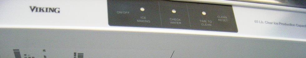
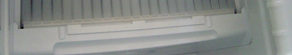
6 Air Flow The machine takes in room temperature air at the lower right front and forces warm air out the lower left front. Restricting the airflow will adversely affect the ability of the ice machine to make ice. Control panel Ice making area Warm air out Air intake Viking Ice machines are designed and manufactured with the highest regard for safety and performance. They meet or exceed the standards of agencies like U.L. Viking assumes no liability or responsibility of any kind for products manufactured by Viking that have been altered in any way, including the use of any parts and/or other components not specifically approved by Viking Viking reserves the right to make design changes and/or improvements at any time. Specifications and designs are subject to change without notice. SMR
7 Water Quality All water, including potable water supplied by municipalities, contains some impurities or minerals. Water absorbs impurities from the air as rain and/or as it flows through the ground. Some of the impurities are solid particles, these are known as suspended solids, and a fine particle filter will remove them. Other impurities are chemically bonded to the water molecules, and cannot be filtered out, these are called dissolved solids. Ice made by this machine will have a lower mineral content than the water it was made from. This is due to the method of making ice. Purer water will freeze first in the ice making molds. The reason for this is that anything dissolved in water lowers the water s freezing temperature. This concentrates most of the impurities in the ice machine water reservoir where they may form hard deposits known as scale. The machine dilutes the concentration of minerals by over-filling the reservoir during the harvest cycle (with the excess water flowing down the drain). s. Between 2 and 4 pints of water flow into the unit each cycle. Between 1 and 3.5 pints of that rinses the reservoir and goes down the drain. Some impurities will inevitably remain, and will stick to the parts in the machine, and will cause malformed ice cubes. Eventually, built up mineral scale can shorten machine life. To keep the machine operating properly, these impurities or minerals will have to be regularly dissolved by an acid cleaning, using an Ice Machine Scale Remover solution. Directions for this may be found in the section under cleaning. Filters and Treatment In general, it is always a good idea to filter the water. A water filter, if it is of the proper type, can remove taste and odors as well as particles. Some methods of water treatment for dissolved solids include reverse osmosis, and polyphosphate feeders. RO Water This machine can be supplied with Reverse Osmosis water, but the water conductivity must be no less than 10 microsiemens/cm. A reverse osmosis system should include post treatment to satisfy the R.O. water s potential aggressiveness. Deionized water is not recommended. Because water softeners exchange one mineral for another, softened water may not improve water conditions when used with ice machines. Where water is very hard, softened water could result in white, mushy cubes that stick together. If in doubt about the water, contact a local point of use water specialist for recommendations on water treatment. Installation Overview The ice machine must: be connected to cold, potable water be connected to a drain be connected to the proper power supply be able circulate air through the vents at the front. Note: Do not build in so that the door is recessed. SMR
8 Door Covering Door Panel The ice machine is supplied without a conventional door covering so it can be decorated to the user s preference. Viking offers several coverings in addition, a custom built panel can be placed onto the door. Custom Panel A custom panel of wood or other material not exceeding 15 lb can be attached to the door. Attachment is from the ice side of the door. Holes are provided in the door for this purpose. See instructions in information packet to create Door Panel Attachment To attach a Viking supplied panel: Note: If door swing is to be changed, it must be done before panel is attached. The panel will be held on by 6 screws and 2 machine screws (Supplied with machine). 1. Remove the gasket and retain for later use. 2. If the door panel is stainless steel, remove any plastic covering the stainless steel panel. 3. Place the panel onto the outside of the door, and secure it to the door using two machine screws, located at the left center and right center. 4. Fasten the panel to the door using the 6 screws. In the hinge area, use the outermost screw holes. 5. Place the covers over the hinge areas, and secure each cover to the door using a sheet metal screw 6. Insert hole plug over screw installed in step 5 7. Return the gasket to its original position. SMR
9 Door Panel Attachment SMR
10 Custom Panel A custom panel of wood or other material not exceeding 15 lb can be attached to the door. Attachment is from the ice side of the door. Holes are provided in the door for this purpose. To create and attach a custom panel: Panel width: 14 7/8 th Panel height: 30 5/16 th. Panel thickness: 5/8 th to ¾ 10. Mount panel to door using wood screws or supplied panel mounting screws. Note: When installed Ice machine must be adjusted for height to position top of door to desired clearance. 1. Measure overall height of cabinet opening where ice machine will be (floor to bottom of countertop edge). 2. Determine desired kickplate space (from bottom of door to floor). This could be equal to the adjacent cabinet s kickplate space or another space the user wants. 3. Subtract kickplate space from cabinet opening. 4. Subtract 1/8 or more for clearance space between top of door and bottom of countertop edge from cabinet opening. This is the maximum door length. 5. Cut panel to width. 6. Cut panel to length (cabinet space - kickplate space - top clearance = length). 7. Determine top of panel. 8. Mark hole locations using drawing on the back of these instructions. Drawing assumes top of panel will be flush with top of door. Measure hole locations from the top of the panel. 9. Drill pilot holes for wood screws. Use drill stop to prevent drilling through the panel. SMR


11 Door Swing Change The door can be attached to open with hinges on the left or right using new brackets shipped loose in the ice bin. Retain all screws for re-use. 8. Remove the upper hinge and move it to the door's opposite side, bottom location. Secure using the original screws. To change: 1. Remove hinge cover (white) and then innermost screw holding each hinge to cabinet, loosen the other. Hinge cover 9. Remove the original lower hinge and move it to the door's opposite side, upper location. Secure using the original screws. 10. Install a screw removed in step 2 in outermost hole of upper and lower cross braces. 2. Slide hinges to the side and remove door from cabinet. Remove screws loosened in step 1 from both hinge brackets. 3. Remove two screws securing top panel to back, pull top panel back and remove from cabinet. 4. Remove two screws at the top and lift the door hinge bracket out of the cabinet. Replace with the one supplied loose with the machine. Fasten it to the cabinet using the original screws. 5. Return the top panel to the cabinet and fasten it with the original screws. 6. Remove kickplate and front service panel. 7. Remove two front screws and two bottom screws holding the bottom cross brace to the cabinet. Replace the brace with the one supplied loose with the machine. Secure it using the original screws. Door Hinge Bracket 11. Attach the door to the cabinet using the original screws. 12. Return kickplate and front service panel to their original positions and attach to the cabinet using the original screws. Installation Notes Built In Situations: If a finished floor is to be installed in the area after the ice machine has been built in, shims the expected thickness of the floor should be installed under the unit to keep the machine level with the planned floor level. Installations on a slab: Use a pump model and pump the water to the point of drainage. Pump models will pump 1 story (10 feet) high. Installations over a crawl space or basement: Either gravity drain or pump model units may be used, if there is not enough room behind the machine for a drain/waste receptacle, the drain will have to be below the floor Note: When installed in a corner, the door swing may be limited due to handle contact with the wall or cabinet face. Screw below SMR


12 Installation: Water & Drain The recommended water supply tubing is ¼ inch OD copper. Stainless steel flex or reinforced PVC tube may also be used. Install an easily accessible shut-off valve between the supply and the unit. This shut-off valve should not be installed behind the unit. Note: Do not use self-piercing type valves. 1. Remove the front service panel by removing the stainless steel cover. Using a small flat blade screwdriver, remove cover. Drains There are two types of ice machine models, one that drains by gravity and one that has an internal drain pump. Drain Pump Model drain installation 1. Locate the coil of 3/8 ID plastic drain tubing secured to the back of the unit. 2. Route the plastic drain tube from the back of the unit to the drain connection point. IMPORTANT NOTE: Often an air gap is required by local codes between the ice maker drain tube and the drain receptacle. 2. With the cover removed, insert a Phillips head screwdriver and remove the securing screw. Remove the service panel. 3. Route the tubing through the right hole in the back to the inlet water solenoid valve inlet. Water inlet tube (field supplied) 4. Install a compression fitting on the tubing and connect to the inlet of the solenoid. Drain tube, route to building drain Back View Drain pump model SMR
13 Gravity Drain Caution: Restrictions in the drain system to the machine will cause water to back up into the ice storage bin and melt the ice. Gravity drain tubing must be vented, have no kinks and slope to the building drain. Air gaps are typically required by local code. 1. Place the ice machine in front of the installation opening. Adjust leveling legs to the approximate height. 2. Remove the front service access panel and the.upper back panel (if needed) Note: If you are connecting a gravity drain model and the drain opening has been located in the floor under the base pan according to the pre install specifications, follow steps 3 through 5 to drain the unit through the base. If not, proceed to step 6b. 4. Connect a straight 5/8 barbed connector to the drain hose, securing with the clamp removed in step Cut an 8 piece of 5/8 ID X 7/8 OD tygon (clear plastic) tubing. Slide one end of the tube onto the outlet of the barbed connector and secure with a clamp. Leave the other end of the tube lying on the floor of the base pan until the unit is positioned over the floor drain. 6. Route the drain tube. Either a) Insert the drain tube through the base pan into the floor drain or b) Route the drain tube through the left hole in the lower back panel and connect to barbed elbow and secure with a clamp. 7. Reinstall the upper back panel (if removed in step 2) 8. Reinstall the service access panel. Level the unit. 3. Remove the clamp and barbed elbow and take off the plastic cover in the base pan below the drain hose. Drain Hose Barbed Elbow Drain Hose, Route to building drain Back View Gravity Drain model SMR

14 Electrical The ice machine is supplied with a power cord. Do not remove the grounding pin from the cord s plug. Do not use extension cords. Follow all codes. Connect the machine to its own 115 volt, 15 amp circuit. 1. If the electrical outlet for the ice maker is behind the unit, plug in the unit. 2. Position the unit in the installation opening. 3. Turn on the water supply. Make sure that the ice maker is plugged in and the power is on. 4. Slide unit into installation opening, paying careful attention to water supply and drain connections. Do not kink! 5. Pour a couple of quarts of water into the ice storage bin; on drain pump equipped machines the drain pump should start and water should pump out. Check for leaks. 6. Replace the service access panel. 7. Level the unit as needed. Installation check list: 1. Has the unit been connected to the proper water supply? 2. Has the water supply be checked for leaks? 3. Has the unit been connected to a drain? 4. Has the drain been tested for flow and leaks? 5. Has the unit been connected to the proper electrical supply? 6. Has the unit been leveled? 7. Have all packing materials been removed from the machine? 8. Has the door covering been installed? Initial Start Up 1. Turn on the water supply. 2. Switch on the electrical power. 3. Push and release the On/Off switch to start the machine. The Ice Making light next to the On/Off switch will glow Blue. 4. The compressor will start and water will begin to flow into the unit. When the reservoir is full, water will start to drain from the machine. After a few minutes the water pump and fan motor will begin to operate and the first ice making cycle will have begun. No adjustments are needed. After about a half hour, ice will fall into the ice storage bin. The machine makes 24 cubes per batch. It is normal for the first batches of ice to melt, that continues until the bin has cooled. It will take 8 to 10 hours of continuous run time to fill the ice bin. When the bin is full of ice, the ice machine will shut off. It will automatically restart when the ice level falls, either from use or normal meltage. SMR
15 Cube Size Adjustment The cube size can be adjusted by changing the amount of freeze cycle time. This is done by a button press sequence Side Views of Cubes. Note: There is only one correct cube size. See the illustrations. To adjust cube size: 1. Shut the machine off: If it's off on bin full press and release the On/Off button once, switching the Ice Making light off. If the machine is making ice hold the On/Off button in until the Ice Making light is off. Too Small, Adjust Cycle Longer 2. Press and hold the Clean button for 5 seconds (light on), then release (light out) 3. View the lights. Compare to the table below. Cube Size Change table On/Off Water Clean Default Off Off Off Add 1 minute On Off Off Add 2 minutes Off On Off Add 3 minutes Off Off On Add 4 minute On On On Minus 1 minute Flash Off Off Minus 2 minutes Off Flash Off Minus 3 minutes Off Off Flash Minus 4 Minutes Flash Flash Flash Just Right 4. Select the amount of change. 5. Push and release the On/Off button until the correct light pattern is displayed. 6. Push and release the Clean button to select that setting. Too Large, Adjust Cycle Shorter 7. Push and release On/Off to return to ice making. SMR
16 Harvest Time Adjustment Control Settings The harvest time can be adjusted so that all the ice harvests during the cycle, plus a few seconds extra. This is done by a button press sequence. Note: Do not set harvest time shorter than the actual time it takes to release all the cubes. To adjust Harvest Time: 1. Shut the machine off by holding the On/Off button in until it shuts off (Ice Making light off). 2. Press and hold the On button again for 5 seconds, then release (Ice Making light will switch off). 3. View the lights. Compare to the table below. Harvest Time table On/Off Water Clean Default Off Off Off Add 10 Seconds On Off Off Add 20 Seconds Off On Off Add 30 Seconds Off Off On Add 40 Seconds On On On Minus 10 Seconds Flash Off Off Minus 20 Seconds Off Flash Off Minus 30 Seconds Off Off Flash Minus 40 Seconds Flash Flash Flash 4. Select the amount of change. 5. Push and release the Clean button until the correct light pattern is displayed. 6. Push and release the On button to select that setting. Automatic water purge enable / disable The control is set at the factory to automatically select the proper amount of water purge. If desired, that can be disabled, and a typical purge amount used. To disable Automatic purge selection: 1. Press and hold the On/Off button until the unit shuts off. No lights should be on. 2. Press and hold the ON button for 5 seconds, then release. 3. Wait between 5 and 20 seconds, then repeat step 1. All lights will flash once. To return to Automatic purge selection: 1. Press and hold the ON button for 5 seconds, then release. 2. Wait between 5 and 20 seconds, then repeat step 1. All lights will flash twice. Manual Harvest - from the OFF or Standby Mode (powered but no lights are on) 1. Press and hold the Clean-Reset button for 5 seconds and release. 2. Wait between 5 and 20 seconds, then repeat step 1. All lights will flash once. The On/Off light will be on until harvest has timed out. Reset time to clean indicator light Press and hold the Clean-Reset button for 3 seconds. 7. Push and release On/Off to return to ice making. SMR

17 Usage and maintenance No special instructions are needed for use. Just take as much ice as you need, the machine will replace it. A scoop is provided, and it can be stored in the machine using the loop of tubing on the right side as a holder. The machine can be shut off anytime by just pushing and releasing the On/Off button. The machine will shut off at the end of the next cycle. To shut off immediately, push and hold the On/Off button in until the machine stops. What shouldn t be done? Never keep anything in the ice storage bin that is not ice. Objects like wine or beer bottles are not only unsanitary, but the labels can slip off and plug up the drain. Never allow the machine to operate without regular cleaning. The machine will last longer if it is kept clean. Regular cleaning should happen at least once per year, and preferably twice. Some water conditions will dictate even more frequent cleaning of the ice making section, and some carpets or pets will dictate more frequent cleaning of the condenser. Note: The Time to Clean light will switch ON after 6 months of use. It will remain ON until the ice making system is cleaned using the process on page 13. Noise: The ice machine is designed for quiet operation, but will make some noise during the ice making cycle. During a freezing cycle, it is normal to hear the fan moving air and the water pump circulating water. Ice hitting the bin or ice in the bin can be heard during harvest. If ice making noise is objectionable, an appliance grade timer can be added to the power supply. Set the timer to turn the machine off at the time(s) of day when the noise is most objectionable. Normal cubes are tapered cylinders. If the cubes are ragged and mis-shaped, mineral scale must be removed from the ice making system Maintenance There are 5 things to keep clean: 1. The outside cabinet & door. 2. The ice storage bin. 3. The condenser. 4. The ice making system. 5. The ice scoop. How to clean the cabinet. Wipe off any spills on the surface of the door and handle as they occur. If anything spilled on the door or gasket dries onto the surface, wash with soap and warm water to remove. How to clean the ice storage bin. The ice storage bin should be sanitized occasionally. It is usually convenient to sanitize the bin after the ice making system has been cleaned, and the storage bin is empty. A sanitizing solution can be made of 1 ounce of household bleach and two gallons of hot (95oF. 115oF.) water. Use a clean cloth and wipe the interior of the ice storage bin with the sanitizing solution, pour some of the solution down the drain. Allow to air dry. SMR

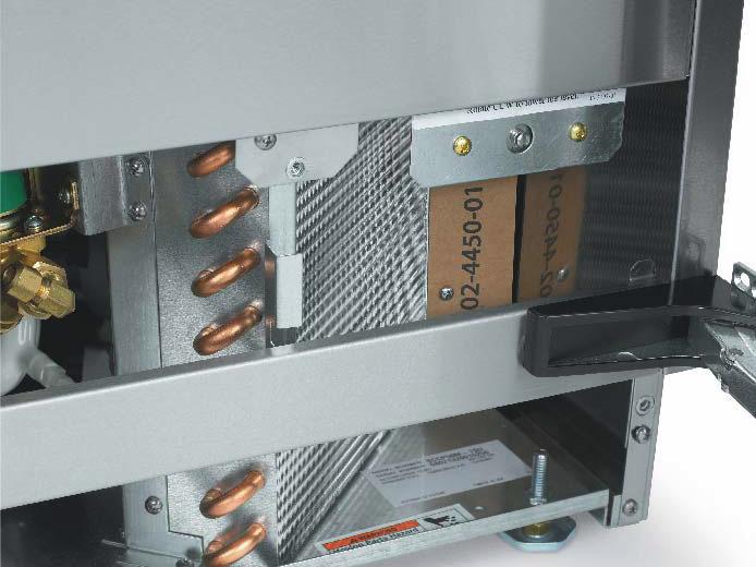
18 Condenser cleaning and winterizing Condenser cleaning The condenser is like the radiator on a car, it has fins and tubes that can become clogged with dirt and lint. To clean: 1. Remove the kickplate and front service panel. 2. Locate the condenser surface. Winterizing 1. Clean the ice making system. 2. Open the door and push and release the On/Off switch to turn the machine off. 3. Turn off the water supply. 4. Drain the water reservoir by removing the rubber cap under the reservoir - it's near the back wall of the ice storage bin. Rubber Cap 3. Vacuum the surface, removing all dust and lint. Caution: Do not dent the fins. 4. Return the kickplate and front service panel to their original positions. Fasten them to the cabinet using the original screws. 5. Disconnect the incoming water line at the inlet water valve. 6. Open the door, push and release the on/off switch to turn the machine on. 7. Blow air through the inlet water valve; a tire pump could do the job. 8. Drain pump models should have about 1/2 gallon of RV antifreeze (propylene glycol) poured into the ice storage bin drain. Note: Automotive antifreeze must NOT be used. 9. Switch off and unplug the machine. SMR


 into the ice machine reservoir. 14.")

19 De-Scaling 1. Scoop out all of the ice, either discard it or save it in an ice chest or cooler. 2. Press and HOLD the On/off button in for 3 seconds until the Blue light goes out. 3. Press and HOLD the both the Clean-Reset and On/Off buttons for 5 seconds. The Time to Clean light will blink on and off. 9. Pour a gallon of hot (95 F. 115 F.) water into the bin to flush out the drain. 10. Clean the bin liner of mineral scale by mixing some ice machine scale remover and hot water, and using that solution to scrub the scale off of the liner. 11. Rinse the liner with hot water. 12. Sanitize the bin interior. 13. Replace the ice removed in step Pour 8 ounces of Viking Ice Machine Scale Remover (available from a local Viking Distributor or Dealer) into the ice machine reservoir. 14. Push and release the On/Off button to restart ice making. The ice scoop should be washed regularly, wash it just like any other food container. Pour Scale Remover Here 5. Operate the machine for about ½ hour. 6. Push and release the On/Off switch. The machine will begin to flush out the cleaning solution. 7. Operate the machine for another ½ hour. 8. Push and release the On/Off switch. The machine will stop the cleaning process. SMR
20 System Information Overall: Refrigerant: 8 oz R-134a Compressor: Hermetic, 1300 BTUH, X HP Condenser: Forced draft Fan blade: 5 blade, 7 inch Evaporator: Inverted, 24 cube cells. Tin plated copper, continuous serpentine Metering device: Cap tube Defrost method: Hot gas bypass with water assist Spray method: 6 water jets Water charge: 40 ounces Water valve: 115 volt solenoid,.19 GPM Water fill time: Varies with harvest time & purge setting Spray pump: Pedestal type. Drain pump: Magnetic drive, controlled by pressure switch Purge method: Overflow standpipe Control method: Electronic Cycle control: Thermistor + timers Freeze cycle timer: 10 minutes, Harvest cycle timer: 20 seconds, Cube size adjustment: Freeze timer change. Harvest cycle adjustment: Harvest timer change Bin control: Thermostat. Opens on temperature fall, Cut Out: 35 degrees F. Cut In 45 degrees F. Range is adjustable. Electrical Components: Compressor Fan motor Spray pump motor Drain pump motor Drain pump switch Bin light - LED type Bin light switch - magnetic reed Inlet water solenoid valve Hot gas valve Transformer Controller Water sensor Thermistor Bin thermostat Electrical Sequence: A closed bin thermostat signals to the controller a need for ice. The controller checks for water, if water is needed, the controller opens the inlet water solenoid valve to fill the reservoir. The hot gas valve is open to equalize the system. When the reservoir is full, the compressor, fan motor, water pump are switched on. After 5 seconds the hot gas valve shuts and ice making begins. Water is sprayed up into the inverted cup mold. As the water is cooled and ice begins to form in the cups, the temperature of the evaporator will fall. The freeze cycle continues until the temperature of the thermistor attached to the evaporator outlet tube falls to about zero degrees F. At that point the controller starts a freeze cycle timer, whose default time is 10 minutes. At the end of the freeze cycle's timed portion the controller switches to the harvest cycle. The harvest cycle begins with the controller stopping the water pump and fan motor. At the same time it opens the hot gas valve and the inlet water solenoid valve. The ice is released by the combination of discharge refrigerant gas entering the evaporator serpentine and warming up the copper, plus the inlet water that flows to the evaporator, floods across the plastic platen to warm it up and be pre-chilled for the next cycle. Ice cubes drop individually and harvest continues until the thermistor attached to the suction line warms up to about 50 degrees F. At that point a harvest timer starts, whose default time is 20 seconds. At the end of that time the harvest cycle ends and the freeze cycle restarts. Bin control: The machine's on and off modes are regulated by a bin thermostat. The cap tube for the bin thermostat is in the tube that holds the scoop. The machine will only begin ice making when the thermostat's contacts close. If the contacts re-open before the temperature of the evaporator drops below a preset point, the machine will stop. If the temperature is below that point when the contact s open, the machine will continue through a complete cycle and stop at the end of the harvest cycle. SMR
21 Water System The controller uses a Water Sensor to check for the presence of water in the reservoir and to measure the conductivity of the water. The water sensor consists of two stainless steel probes located in a holder next to the water pump. The probes sense the conductivity of the water. The higher the mineral content of the water, the better it can conduct electricity. The control system is capable of sensing water as clean as 10 microsiemens/cm. If the controller cannot sense water and the bin thermostat is closed the controller will power the inlet water solenoid valve to fill the reservoir. The water fill is timed. There is a maximum amount of time allowed from the time the controller turned on the inlet water valve until the water sensor signals to the controller. That time is 2 minutes. If water is not sensed within 2 minutes, the controller will not proceed with an ice making cycle. Instead it will blink the Water light and try filling the reservoir in 20 minutes. Freeze Cycle Water Schematic Reservoir water dilution The process of making ice from circulating water causes the pure water to freeze first, because it freezes at the warmest temperature. The remaining water will develop an increasing concentration of minerals. If that mineral concentration were allowed to continue, eventually the ice machine would become coated with mineral scale. To combat the mineral build up, the reservoir water is diluted with fresh water every cycle. The controller adds enough water to fill the reservoir and extra water to overfill it. The extra water drains out through the standpipe in the reservoir. The controller keeps the inlet water solenoid valve open until the evaporator temperature set point is reached, plus some extra time. The extra time is either pre-set or automatically determined by the controller. Harvest Cycle Water Schematic SMR
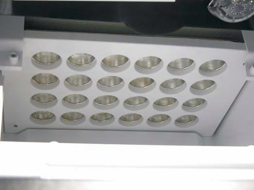
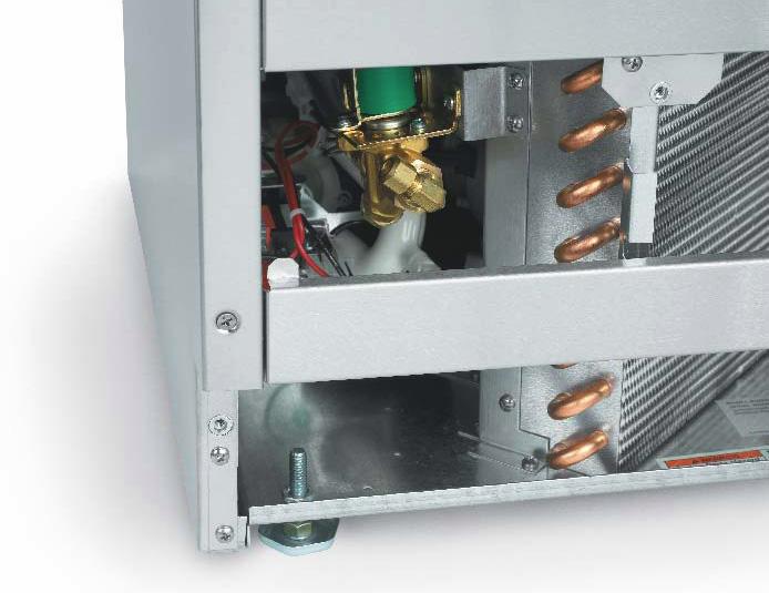
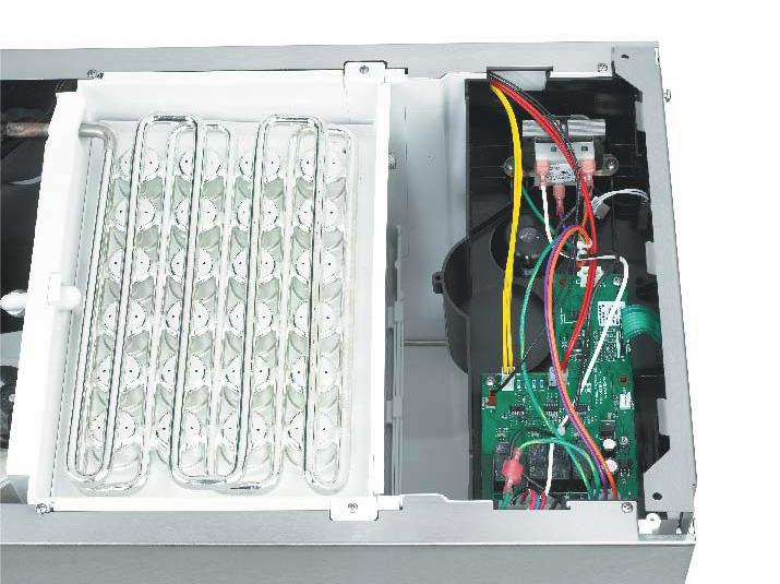


22 Components Model and Serial Tag Scoop and Thermostat Bracket Evaporator and Controller Evaporator Platen Condenser and Bin thermostat Water Inlet valve SMR

23 Controller High Voltage Molex Connector Comp D-14 Bin thermostat Water D-13 Hot Gas D-12 Water Sensor Bin Light Fan & Spray Pump D-11 Power Supply Connector Power D-5 Control Panel Ribbon The controller is located at the front of the unit, under the top panel. It is powered by a 12 volt transformer. It has 5 indicator lights: Compressor - Light is ON if compressor is Powered Water - Light is ON if inlet water solenoid valve is powered Hot Gas - Light is ON when Hot Gas Valve is Powered Fan - Light is ON when Fan motor and Spray Pump are powered Power - Light is ON when power is connected to controller Control Safeties: No Water. If the Water Sensor cannot detect water, and the inlet water solenoid valve has been on for the maximum fill time, the controller will stop all action and wait 20 minutes to re-try water fill. During this time the Check Water light on the control panel will be blinking, Maximum Freeze Time. If the freeze cycle should extend to 60 minutes, the controller will automatically put the machine into a Harvest cycle. Maximum Harvest Time. 6 minutes Time between restarts. After the machine has operated and then turned off, the controller will not restart the machine for four minutes. SMR
24 Performance Information Freeze Cycle Time Air Temperature Freeze Cycle, Minutes Water Temperature Harvest Cycle Time Air Temperature Harvest Cycle, Seconds Water Temperature Total Cycle Time Air Temperature Total Cycle, Minutes Water Temperature Ice per cycle: 1 lb Water drained / cycle: Varies by harvest cycle length and purge setting. Typical amounts 70/50 = 52 90/70 = 13 oz Compressor amps: SMR
25 Refrigeration System SMR
26 Thermistor Values Deg F Ohms Deg F Ohms Deg F Ohms Deg F Ohms Deg F Ohms SMR
27 Service Diagnosis No Ice Problem Likely Cause Probable Solution No power to unit Power disconnected Check breaker or fuse. Reset or replace, restart and check No power to controller Transformer open Replace transformer Shut down on maximum water fill time -water light flashing Water shut off Water leak Dirty condenser Restricted location, intake air too hot or blocked Evaporator thermistor not sensing properly Restore water supply Check curtain, sump Clean condenser Eliminate restriction, have machine moved Check thermistor Very long freeze cycle Spray jets dirty Remove spray platform and clean spray jets Cannot make ice Inlet water valve leaks through during freeze Low on refrigerant Connected to hot water Spray pump not pumping Fan motor not turning Pump hose disconnected Very low on refrigerant Compressor not operating Hot gas valve leaks through during freeze Compressor inefficient Check inlet water valve Check cube formation, Check for bleed thru from / missing check valve in building water supply Check pump motor Check fan motor, check fan blade, check controller for voltage output Check hose Add access valve, add refrigerant as a test. If unit makes ice, find and correct leak. Check compressor start components, check PTCR resistance and temperature Check compressor voltage Check compressor windings Check hot gas valve for hot outlet during freeze Check compressor amp draw, if low and all else is correct, change compressor SMR
28 Service Diagnosis Makes Excessive Noise Problem Likely Cause Probable Solution Fan blade vibrates Compressor vibrates Water pump vibrates Makes Ice but does not Harvest Blade is bent Fan motor mount is broken Mounting loose Pump bearings worn Replace fan blade Replace motor mount Panels vibrate Mounting screws loose Tighten screws Check mounting Replace pump Problem Likely Cause Probable Solution Ice wrong size Environment changed Adjust cube size Little heat to evaporator Hot gas valve does not open Water temperature very low Fan motor does not stop Check voltage to coil when unit is in harvest, check controller indicator light. Adjust harvest time Check voltage, replace controller Makes Poor Quality Ice Problem Likely Cause Probable Solution Spray pattern poor Spray jets dirty Clean jets Runs out of water Water leaking from reservoir Correct leak High TDS water supply Groundwater supply Treat water Makes Ice but melts rapidly Problem Likely Cause Probable Solution Restricted drain Gravity drain hose has air block Check for kinks or traps Pooled water in bin Pump model switch not starting pump Check / replace switch SMR
29 Removal and Repair Bin Thermostat 1. Disconnect electrical power. 9. Reverse to reassemble. Curtain 1. Shut unit off. 2. Loosen both thumbscrews holding curtain bracket to freezing chamber. 3. Pull out and remove curtain with bracket from ice machine. 4. Reverse to reassemble. 2. Remove service panel. 3. Remove back panel. Note: If unit is built in it must be pulled out to change the bin thermostat. 4. Pull cap tube out from the back of the ice storage bin and cap tube holder. 5. Remove two screws and the bin thermostat contact section from its mounting bracket. 6. Disconnect two wires from the bin thermostat contact section and remove the thermostat from the ice machine. 7. Reverse to reinstall. Inlet Water Solenoid Valve 1. Disconnect electrical power. 2. Remove service panel. 3. Shut water supply OFF. 4. Disconnect inlet water supply tube from inlet water solenoid valve. Spray Platform 1. Remove curtain. 2. Lift spray platform up until it disconnects from its fitting. 3. Pull forward and remove from the ice machine. 4. Reverse to reassemble. Water Pump 1. Remove spray platform 2. Remove back panel. Note: If unit is built in it must be pulled out to change the water pump. 3. Disconnect power and ground wires from pump motor. 4. Rotate pump body CW and lift up to remove it. 5. Reverse to reassemble 5. Unplug wire harness from valve coil. 6. Remove two screws holding valve to chassis. 7. Squeeze hose clamp larger and push away from solenoid valve outlet. 8. Pull hose from outlet of valve. SMR
30 Removal and Repair Evaporator Thermistor Note: If unit is built in it must be pulled out to change the evaporator thermistor. 5. Remove screws holding transformer to controller box and pull transformer up and out of the ice machine. 6. Reverse to reassemble. Controller Note: If unit is built in it must be pulled out to change the controller. 1. Disconnect electrical power. 2. Remove top panel 1. Shut machine off. If unit was making ice, manually harvest the ice. 2. Disconnect electrical power. 3. Remove top panel. 4. Remove cover from controller box. 5. Disconnect thermistor wire from controller. 6. Locate thermistor sensor, it is attached to the suction line, just above the accumulator and is covered with insulation tape. Remove the insulation. 7. Disconnect sensor bulb from suction line (it's held on with a metal clip). 8. Remove thermistor from ice machine. 9. Reverse to reassemble. It is very important that the bulb be re-insulated. Transformer Note: If unit is built in it must be pulled out to change the transformer. 1. Disconnect electrical power. 2. Remove top panel. 3. Remove controller cover. 4. Unplug leads from transformer. 3. Remove controller box cover. 4. Unplug all connections. 5. Remove screws holding controller to housing, and lift controller from unit. Note: To avoid damaging the controller, touch the metal chassis of the unit prior to touching the replacement controller. 6. Reverse to reassemble. Control Panel 1. Disconnect electrical power. 2. Remove top panel 3. Remove controller box cover. 4. Unplug ribbon cable connection. 5. Push control panel away from the front of the machine. Begin at the ribbon cable attachment point. Note: Control panel is held on by adhesive and the adhesive is thinnest at the cable point. 6. Separate control panel from controller box and remove from the ice machine. 7. Reverse to reassemble SMR


31 Removal and Repair Certain components require the removal of the cabinet for repair access. 12. Remove curtain & hanger. 1. If the machine is in a freeze mode, perform a manual harvest. 2. Remove all ice. 3. Drain reservoir. 4. Remove service panel and kick plate. 5. Remove back panel. 6. Disconnect electrical power. 13. Locate elbows where water flows onto the evaporator platen. Inlet Elbow Clip 7. Disconnect water and drain tubing. 8. Remove door. 9. Remove top panel. 10. Remove controller box cover. 11. Disconnect thermistor from controller, pull wire back to suction line. 14. Pull clip up. Push inner elbow back and rotate it until it points straight up, then push it back through the hole in the back of the freezing compartment. Thermistor Connection Inner Elbow Inlet Elbow SMR


32 Removal and Repair 18. Remove two screws holding freezing compartment brace to cabinet, lift brace up. Brace 23. Lift bin assembly off the base. Note: Prop evaporator assembly up. A 3' length of 3/4" PVC tubing with one end inserted into the cup mold and the other against the base will hold it up. The hot gas valve, fan motor, condenser and compressor are now exposed for service. 19. Lift evaporator platen up and tilt back enough for bin assembly to clear the base. Chassis Shown in Front of Bin Assembly Air Baffle 20. Remove air baffle. 21. Unplug 7 wire harness connector (at back of bin). 22. Remove 1 screw at each corner of the base SMR
33 Refrigeration Service This ice machine use R-134a type refrigerant. There are specific rules for handling that refrigerant. To check for system pressures, add a field supplied clamp-on type service valve as a temporary means of system access. After diagnosis and before final repair, replace the clamp-on type valve with valves that are brazed onto the process tubes of the system. Use a low flow of dry nitrogen when brazing on the system. Install a new filter drier when replacing a refrigeration component or after a refrigerant leak repair. Evacuate the system to at least 300 microns and use a micron gauge to measure the evacuation level. Weigh in the nameplate charge. The machine is critically charged and a partial ounce mis-charge will affect performance. SMR
34 Schematic Diagram SMR
35 Wiring Diagram Wiring Diagram SMR
Installation and User's Manual for Residential Ice Machine. Models SCCG30 and SCCP30
 Installation and User's Manual for Residential Ice Machine Models SCCG30 and SCCP30 Introduction: This ice machine is the result of Scotsman s decades of experience in the design and manufacturing of both
Installation and User's Manual for Residential Ice Machine. Models SCCG50 and SCCP50
 Installation and User's Manual for Residential Ice Machine Models SCCG50 and SCCP50 SCCG50 & SCCP50 Introduction: This ice machine is the result of Scotsman s decades of experience as an industry leader
Installation and User's Manual for Outdoor Model Residential Ice Machine. Models SCCG50M-1SS and SCCP50M-1SS
 Installation and User's Manual for Outdoor Model Residential Ice Machine Models SCCG50M-1SS and SCCP50M-1SS SCCG50 & SCCP50 - Outdoor Model Introduction: This ice machine is the result of Scotsman s decades
SCCG30 & SCCP30 Service Manual Introduction:
 Introduction: This ice machine is the result of Scotsman s decades of experience as an industry leader in the design and manufacture of both commercial and residential ice machines. This manual includes
SCCG50 & SCCP50 Service Manual Introduction:
 SCCG50 & SCCP50 Introduction: This ice machine is the result of Scotsman s decades of experience as an industry leader in the design and manufacture of both commercial and residential ice machines. This
SCCG50 & SCCP50 Service Manual Introduction:
 Introduction: This ice machine is the result of Scotsman s decades of experience as an industry leader in the design and manufacture of both commercial and residential ice machines. This manual includes
Installation. 15 W. Undercounter/Freestanding Ice Machine FGIM515 / CFGIM515 FPIM515 / CFPIM515
 Installation 15 W. Undercounter/Freestanding Ice Machine FGIM515 / CFGIM515 FPIM515 / CFPIM515 TABLE OF CONTENTS Warnings & Important Safety Instructions 3 Dimensions (Professional) 5 Dimensions (Custom
Installation and User's Manual for Residential Nugget Ice Machine. Model SCN60
 Installation and for Residential Nugget Ice Machine Model SCN60 Introduction This manual includes information for the installation, operation and maintenance of the SCN60 residential ice machine. The SCN60
Viking Use & Care Manual
 Viking Use & Care Manual Viking Range Corporation 111 Front Street Greenwood, Mississippi 38930 USA (662) 455-1200 For product information, call 1-888-VIKING1 (845-4641) or visit the Viking Web site at
Scotsman Technical Training. CU50 Cube Ice Machine
 Scotsman Technical Training CU50 Cube Ice Machine Major Topics Overview Installation Start Up Sequence of Operation Maintenance Diagnostics Service Procedures Models Two Base Models Gravity Drain Pump
Use & Care. 15 W. Undercounter/Freestanding Ice Machine FGIM515 / CFGIM515 FPIM515 / CFPIM515
 Use & Care 15 W. Undercounter/Freestanding Ice Machine FGIM515 / CFGIM515 FPIM515 / CFPIM515 CONGRATULATIONS Congratulations and welcome to the elite world of appliance ownership. We hope you will enjoy
Installation Guide. 15 W. Undercounter/Freestanding Nugget Ice Machine U L. Viking Range, LLC. 111 Front Street
 Installation Guide Viking Range, LLC 111 Front Street Greenwood, Mississippi 38930 USA (662) 455-1200 For product information, call 1-888-(845-4641) or visit our web site at vikingrange.com in the US or
DCE33 INTRODUCTION. Table of Contents. Parts lists and wiring diagrams are located in the center of the manual.
 INTRODUCTION The Scotsman is a restaurant type ice machine designed for home use. It produces the same high quality ice as large Scotsman commercial ice cube machines, and stores that ice in a heavily
Table of Contents SPECIFICATIONS Page 2. FOR THE INSTALLER Page 3. FOR THE PLUMBER Page 4. INSTALLATION Page 5. INITIAL START UP Page 6
 INTRODUCTION This service manual covers the installation, operation, maintenance and service of this ice machine. Table of Contents SPECIFICATIONS Page 2 FOR THE INSTALLER Page 3 FOR THE PLUMBER Page 4
SCN60 Residential Nugget Ice Machine
 SCN60 Residential Nugget Ice Machine SCN60 Nugget Ice Nugget Ice What it isn t: Ice frozen in a mold What it is: A chewable ice, formed continuously by forcing soft ice thru tapered holes. Components Compared
installation and operation MODEL 315 ice maker
 installation and operation MODEL 315 ice maker InTRODUCTION Contents Introduction................................ 2 Pre-Installation............................. 3-5 Installation...............................
Outdoor Use Notice: NU130 Installation and Use Introduction
 Installation and Use Introduction This manual includes information for the installation, operation and maintenance of the NU130 residential ice machine. The NU130 was developed to offer fans of Scotsman
ICE MAKER Use & Care Guide. Table of Contents... 2
 ICE MAKER Use & Care Guide Table of Contents... 2 2217247 ICE MAKER SAFETY...2 ICE MAKER INSTALLATION...3 Unpacking...3 Location Requirements...3 Electrical Requirements...3 Leveling...4 Water Supply Connection...4
Table of Contents. Specifications... page 2. Installation... page 3. Customizing... page 4. Reversing door swing... page 5
 Introduction The Scotsman Compact Refrigerator is a unique product, capable of being built into a cabinet because of its front vented, forced-air cooling system. It s also designed to be a companion to
CME256, 506, 656, 806: AutoIQ Cubers
 Introduction: CME256, 506, 656, 806: AutoIQ Cubers This product manual contains the information needed for the setup, installation, initial start up, sanitation and maintenance of this ice machine. Keep
Installation and User's Manual for Cuber Model CU0515
 Installation and User's Manual for Cuber Model CU0515 CU0515 INTRODUCTION This manual provides the specifications and the step-by-step procedures for the installation, startup, operation, maintenance and
Technical Training Prodigy Undercounter Cubers. Models CU1526, CU2026 and CU3030
 Technical Training Prodigy Undercounter Cubers Models CU1526, CU2026 and CU3030 List of Major Topics Introduction Installation Operation Maintenance Diagnosis Service Prodigy with a Bin 3 models CU1526
M ODELS 315I AND 315IP ICE M AKER INSTALLATION &OPERATION
 M ODELS 315I AND 315IP ICE M AKER INSTALLATION &OPERATION CONTENTS Models 315I and 315IP Installation 4 Installation Checklist 13 Models 315I and 315IP Features 14 Models 315I and 315IP Operation 15 Troubleshooting
CME456R. Introduction
 Introduction This product manual contains the information needed for the setup, installation, initial start up, sanitation and maintenance of this ice machine. Keep it for future reference. Be certain
Eclipse Technical Training CME686 CME810 CP686 CP886 CP1086
 Eclipse Technical Training CME686 CME810 CP686 CP886 CP1086 In This Presentation What Eclipse is Components and their functions Installation Operation Maintenance Service Diagnosis The Eclipse System The
Owner / Operator Use and Care Guide I SERIES 224 ICE CUBE MACHINE
 Owner / Operator Use and Care Guide I SERIES 224 ICE CUBE MACHINE THE HOTTEST MACHINES ON ICE CORNELIUS INC www.cornelius.com IMPORTANT: TO THE INSTALLER. It is the responsibility of the Installer to ensure
INSTALLATION INSTRUCTIONS
 INSTALLATION INSTRUCTIONS BUILT-IN BOTTOM MOUNT REFRIGERATOR/FREEZER DBRTGK72SS-GRILLE KIT (FOR designer SERIES ONLY) VIKING RANGE CORPORATION 111 Front Street Greenwood, Mississippi (MS) 38930 USA (662)
Hoshizaki America, Inc.
 Hoshizaki America, Inc. Self-Contained Flaker Model F-330BAH(-C) A Superior Degree of Reliability INSTRUCTION MANUAL www.hoshizaki.com Issued: 5-4-2007 Revised: 1-15-2013 WARNING Only qualified service
Installation and User's Manual for Flake and Nugget Ice Machine. Models FME504, FME804, NME454, NME654
 Installation and User's Manual for Flake and Nugget Ice Machine Models FME504, FME804, NME454, NME654 INTRODUCTION To the owner or user: This manual is intended to provide you with the information needed
Automatic Undercounter Ice Maker
 Automatic Undercounter Ice Maker User s Manual Be sure ice maker is standing upright 24 hours prior to plug-in. Model: HI50IB20SS TABLE OF CONTENTS Page ICE MAKER SAFETY... 2 IMPORTANT SAFEGUARDS...3-5
Water Boilers ME10EN, ME15EN. Table of Contents
 Water Boilers ME10EN, ME15EN Operator Manual Model ME15EN Model ME10EN Safety Information...2 Rough-In Drawing...3 Installation...4 Priming...5 Cleaning...5 Table of Contents Adjustments...6 Maintenance...7
CME306 & CME456 INTRODUCTION
 INTRODUCTION This product manual contains the information needed for the setup, installation, initial start up, sanitation and maintenance of this ice machine. Keep it for future reference. Be certain
Prodigy Eclipse Cuber Technical Training
 Prodigy Eclipse Cuber Technical Training 600 800 1000 1200 1400 1800 2000 In This Presentation What Eclipse is Components and their functions Installation Operation Maintenance Service Diagnosis The Prodigy
Service Manual for Cuber Model CS0415
 for Cuber Model Introduction This is the service manual for the ice machine. Note and heed any warning symbols where they appear. Basic installation information is provided, however the installation manual
Hoshizaki America, Inc.
 Hoshizaki America, Inc. Modular Crescent Cuber Models KM-1340MAH KM-1340MWH KM-1340MRH A Superior Degree of Reliability INSTRUCTION MANUAL www.hoshizaki.com Issued: 8-11-2005 IMPORTANT Only qualified service
Installation and User Manual for Model UF424 and UN324
 Installation and User Manual for Model UF424 and UN324 To the owner or user: the service manual is intended to provide you and the maintenance or service technician with the information needed to install,
UF424 and UN324. Technical Service
 UF424 and UN324 Technical Service Technical Service 1-800-533-6006 Check out the new mobile ready website www.scotsman-ice.com/service Technical Service Virtual Business Card What you will learn Introduction
SELF-CONTAINED CRESCENT CUBER
 Reliability is a beautiful thing TM SELF-CONTAINED CRESCENT CUBER KM-250BAF KM-250BWF INSTRUCTION MANUAL ISSUED: March 14, 2000 REVISED: December 22, 2004 IMPORTANT Only qualified service technicians should
PERLICK PRODUCT MANUAL SELF-CONTAINED ICE MAKER MODELS: H50IMS-R H50IMS-L H50IMW H50IMS-ADL H50IMS-ADR H50IMW-AD
 PERLICK SELF-CONTAINED ICE MAKER MODELS: H50IMS-R H50IMS-L H50IMW H50IMS-ADL H50IMS-ADR H50IMW-AD PRODUCT MANUAL Issued: 11-2-2009 IMPORTANT This manual should be read carefully before the icemaker is
INSTALLATION MANUAL. Series 322 Ice Cube Machine SPECIFICATIONS UNPACKING. Series 322 Ice Cube Machine Installation Instructions
 INSTALLATION MANUAL Series 322 Ice Cube Machine SPECIFICATIONS 7.00 15.00 C A 6 ft electrical cord 1.00 2.00 22.00 5.00 Front 16.38 11.25 5.00 F E Air In D 2.75 2.25 14.75.75 B 23.50 21.00 Opening 23.50
Hoshizaki America, Inc.
 Hoshizaki America, Inc. Self-Contained Crescent Cuber Models KM-255BAH KM-255BWH A Superior Degree of Reliability INSTRUCTION MANUAL www.hoshizaki.com Issued: 10-4-2006 IMPORTANT Only qualified service
INSTALLATION INSTRUCTIONS
 INSTALLATION INSTRUCTIONS BUILT-IN BOTTOM MOUNT REFRIGERATOR/FREEZER BRTGK72SS-GRILLE KIT (FOR PROFESSIONAL SERIES ONLY) VIKING RANGE CORPORATION 111 Front Street Greenwood, Mississippi (MS) 38930 USA
SERVICE/INSTALLATION MANUAL ICE ONLY DISPENSERS MODELS-IOD150, IOD200 AND IOD250
 SERVICE/INSTALLATION MANUAL ICE ONLY DISPENSERS MODELS-IOD150, IOD200 AND IOD250 Ice-O-Matic 11100 East 45th Ave Denver, Colorado 80239 Part Number 9081305-01 Date 10/08 Introduction IOD150,IOD200,IOD250
SELF-CONTAINED FLAKER
 Reliability is a beautiful thing TM SELF-CONTAINED FLAKER F-500BAF(-C) INSTRUCTION MANUAL ISSUED: April 13, 1998 REVISED: December 30, 2004 IMPORTANT Only qualified service technicians should attempt to
REFRIGERATOR SAFETY. Your safety and the safety of others are very important.
 REFRIGERATOR SAFETY Your safety and the safety of others are very important. We have provided many important safety messages in this manual for your appliance. Always read and obey all safety messages.
Automatic Ice Maker User s Manual Be sure the ice maker has been standing upright at least 24 hours prior to plug-in.
 Automatic Ice Maker User s Manual Model:BC450/BC600 Be sure the ice maker has been standing upright at least 24 hours prior to plug-in. TABLE OF CONTENTS Page ICE MAKER SAFETY... 2 IMPORTANT SAFEGUARDS...
Hoshizaki America, Inc.
 Hoshizaki America, Inc. Self-Contained Cubelet Models C-100BAE-AD C-100BAE-ADDS A Superior Degree of Reliability INSTRUCTION MANUAL www.hoshizaki.com Issued: 3-25-2008 Revised: 5-20-2009 IMPORTANT Only
Viking Installation Guide
 Viking Installation Guide Viking Range, LLC 111 Front Street Greenwood, Mississippi 38930 USA (662) 455-1200 For product information, call 1-888-(845-4641) or visit the Viking Web site at vikingrange.com
Technical Service Guide May 2008
 GE Consumer & Industrial Technical Service Guide May 2008 MONOGRAM ICEMAKER Models ZDIC150W ZDIS150W Pub. #31-#### GE Appliances General Electric Company Louisville, Kentucky 40225 TABLE OF CONTENTS Page
CME1056R. Introduction
 Introduction CME1056R This product manual contains the information needed for the setup, installation, initial start up, sanitation and maintenance of this ice machine. Keep it for future reference. Be
IB450SSP. Built-in Ice Maker with Internal Pump. Owner s Manual
 Built-in Ice Maker with Internal Pump IB450SSP Owner s Manual For more information on other great EdgeStar products on the web, go to http://www.edgestar.com Important Safety Information Improper handling
HID312, HID525 and HID540 Meridian Ice Maker-Dispensers Technical Service
 HID312, HID525 and HID540 Meridian Ice Maker-Dispensers Technical Service What you will learn Introduction Installation Operation Maintenance Take It Apart Diagnostics HID Ice Maker-Dispensers HID models
Hoshizaki America, Inc.
 Hoshizaki America, Inc. Self-Contained Cuber Models AM-50BAE AM-50BAE-DS AM-50BAE-AD AM-50BAE-ADDS A Superior Degree of Reliability INSTRUCTION MANUAL www.hoshizaki.com Issued: 3-10-2006 Revised: 4-15-2009
INSTRUCTION MANUAL (UNIT APPEARANCE MAY VARY FROM IMAGE) BEFORE USE, PLEASE READ AND FOLLOW ALL SAFETY RULES AND OPERATING INSTRUCTIONS.
 BEFORE USE, PLEASE READ AND FOLLOW ALL SAFETY RULES AND OPERATING INSTRUCTIONS.") INSTRUCTION MANUAL Model Number: FR551 REFRIGERATOR-FREEZER (UNIT APPEARANCE MAY VARY FROM IMAGE) BEFORE USE, PLEASE READ AND FOLLOW ALL SAFETY RULES AND OPERATING INSTRUCTIONS. Igloo has a policy of continuous
INSTRUCTION MANUAL Model Number: FR551 REFRIGERATOR-FREEZER (UNIT APPEARANCE MAY VARY FROM IMAGE) BEFORE USE, PLEASE READ AND FOLLOW ALL SAFETY RULES AND OPERATING INSTRUCTIONS. Igloo has a policy of continuous
Prodigy Plus - D Series Cuber Technical Review
 Prodigy Plus - D Series Cuber Technical Review Water Distributor Control Panel Air Filter ice Thickness Sensor Lower Light and Switch Panel Water Pump Water Level Sensor & Guard Curtain Switch and Magnet
Installation and User s Manual for Cube Ice Machine with storage models HISU050, HISU070 and HISU090
 Installation and User s Manual for Cube Ice Machine with storage models HISU050, HISU070 and HISU090 Introduction The design of this product is the result of years of experience in developing commercial
Installation. Built-in Full Height Wine Cellar VCWB301
 Installation Built-in Full Height Wine Cellar VCWB301 Table of Contents Warnings & Important Information _ 3 Dimensions _ 5 Specifications _ 6 Cutout Dimensions 7 Cabinet Information _ 8 Cabinet Information
Reliability is a beautiful thing TM MODULAR FLAKER F-800MAH(-C) F-800MWH(-C) INSTRUCTION MANUAL
 F-800MWH(-C) INSTRUCTION MANUAL") Reliability is a beautiful thing TM MODULAR FLAKER F-800MAH(-C) F-800MWH(-C) INSTRUCTION MANUAL ISSUED: FEB. 28, 2001 REVISED: DEC. 11, 2003 IMPORTANT Only qualified service technicians should attempt
Reliability is a beautiful thing TM MODULAR FLAKER F-800MAH(-C) F-800MWH(-C) INSTRUCTION MANUAL ISSUED: FEB. 28, 2001 REVISED: DEC. 11, 2003 IMPORTANT Only qualified service technicians should attempt
Includes Prodigy Plus D Models
 Service Manual for Prodigy Eclipse Cubers models EH330 C and EH430 C, with ECC Condensing Unit ECC1200, ECC1410, ECC1800 Includes Prodigy Plus D Models Introduction: This manual covers the assembly, installation,
CME1202 & CME1402 INTRODUCTION. Table of Contents. This manual was printed on recycled paper.
 INTRODUCTION To the owner or user: This service manual is intended to provide you and the maintenance or service technician with the information needed to install, start up, clean, maintain and service
BULL INSTRUCTION MANUAL. Model Number: BC-130 REFRIGERATOR BEFORE USE, PLEASE READ AND FOLLOW ALL SAFETY RULES AND OPERATING INSTRUCTIONS.
 BULL INSTRUCTION MANUAL Model Number: BC-130 REFRIGERATOR BEFORE USE, PLEASE READ AND FOLLOW ALL SAFETY RULES AND OPERATING INSTRUCTIONS. 1 REFRIGERATOR SAFETY Your safety and the safety of others are
Installation Instructions 36 Inch Refrigerator
 Installation Instructions 36 Inch Refrigerator For Use With Models: EF36BNNF, IF36BNNF, PF36BNNF Francis - Voir Page 9 Part No. 106177 Rev. B/13036906 Refrigerator Safety...1 Proper Disposal of Your Refrigerator...1
Hoshizaki America, Inc.
 Hoshizaki America, Inc. Modular Crescent Cuber Models KM-501MAH KM-501MWH KM-501MRH A Superior Degree of Reliability INSTRUCTION MANUAL www.hoshizaki.com Issued: 2-13-2006 IMPORTANT Only qualified service
Hoshizaki America, Inc.
 Hoshizaki America, Inc. Stackable Crescent Cuber Models KM-1301SAH/3 KM-1301SWH/3 KM-1301SRH/3 A Superior Degree of Reliability INSTRUCTION MANUAL www.hoshizaki.com Issued: 9-4-2008 Revised: 2-5-2013 IMPORTANT
CHEST FREEZER INSTRUCTION MANUAL. Model No.: EWCF5WBX EWCF7WBX
 CHEST FREEZER INSTRUCTION MANUAL Model No.: EWCF5WBX EWCF7WBX To ensure proper use of this appliance and your safety, please read the following instructions completely before operating this appliance.
Hoshizaki America, Inc.
 Hoshizaki America, Inc. Modular Crescent Cuber Models KM-461MAH KM-461MWH KM-461MRH A Superior Degree of Reliability INSTRUCTION MANUAL www.hoshizaki.com Issued: 2-13-2006 Revised: 1-28-2008 IMPORTANT
INSTALLATION INSTRUCTIONS UNDERCOUNTER DISHWASHERS
 INSTALLATION INSTRUCTIONS UNDERCOUNTER DISHWASHERS VIKING 111 Front Street Greenwood, Mississippi 38930 USA (662) 455-1200 IMPORTANT - PLEASE READ AND FOLLOW Before beginning - please read these instructions
TABLE OF CONTENTS. NOTE: Read the entire instruction manual before starting the installation. TROUBLESHOOTING... 13
 R 410A Duct Free Split System Air Conditioner and Heat Pump Product Family: DFS4(A/H) System, DFC4(A/H)3 Outdoor, DFF4(A/H)H Indoor NOTE: Read the entire instruction manual before starting the installation.
Eclipse Introduction:
 Introduction: This manual covers the assembly, installation, start up, operation and maintenance of the 2000 remote low side cuber system. Table of Contents Configuration: Page 2 Technical Specifications
September 2006 Page 1
 Introduction This technical manual covers the Prodigy line, excluding the Eclipse remote low side models. All models except Eclipse are shipped with an Installation and User's manual, which can be referred
Installation and User s Manual for Meridian Ice Maker-Dispensers models HID312, HID525 and HID540
 for Meridian Ice Maker-Dispensers models HID312, HID525 and HID540 Introduction The ice maker-dispensers covered in this manual were designed by to be the finest on the market. Their design is a result
Hoshizaki America, Inc.
 Hoshizaki America, Inc. Modular Crescent Cuber Models KM-900MAH50 KM-900MRH50 A Superior Degree of Reliability INSTRUCTION MANUAL www.hoshizaki.com Issued: 6-25-2008 IMPORTANT Only qualified service technicians
2008 DOUBLE DRAWER UNDER COUNTER REFRIGERATOR / FREEZER PRODUCTS
 TECHNICAL EDUCATION R-107 2008 DOUBLE DRAWER UNDER COUNTER REFRIGERATOR / FREEZER PRODUCTS KDDC24RVS KDDO24RVX KDDC24CVS KDDO24CVX KDDC24FVS KDDO24FVX JUD248RCRS JUD248RCCX JUD248CCRS JUD248CCCR JUD248FCRS
SLC400. Introduction. Table of Contents
 Introduction To the owner or user: This service manual is intended to provide you, and the maintenance or service technician, with the information needed to install, start up, clean, maintain and repair
Hoshizaki America, Inc.
 Hoshizaki America, Inc. Low-Profile Modular Crescent Cuber Models KML-451MAH KML-451MWH A Superior Degree of Reliability INSTRUCTION MANUAL www.hoshizaki.com Issued: 2-7-2006 Revised: 8-5-2009 IMPORTANT
Automatic Outdoor Ice Maker User Manual
 Automatic Outdoor Ice Maker User Manual Model: BLZ-ICEMKR-50GR Be sure ice maker is standing upright 24 hours prior to plug-in. TABLE OF CONTENTS Page ICE MAKER SAFETY... 2 IMPORTANT SAFEGUARDS... 3-5
SERVICE MANUAL Undercounter Refrigerator Drawer Units
 SERVICE MANUAL Undercounter Refrigerator Drawer Units Models VURD140 DURD140 DFRD140 VIKING Preferred Service 1803 Hwy 82 West, Greenwood, Mississippi (MS) 38930 USA 662-455-1200 Important Information
Automatic Ice Maker. Service Manual VT ICEMAKER 15
 Automatic Ice Maker Service Manual VT ICEMAKER 15 Table of contents How the Icemaker works 3 10 Cooling System 3 Water System 4 5 Wiring Connections and Controller 6 8 Exploding Drawing 9 10 TroubleShooting
ISSUED: FEB. 23, 1998 REVISED: OCT. 15, 1999 HOSHIZAKI MODULAR FLAKER MODEL F-450MAF(-C)
") ISSUED: FEB. 23, 1998 REVISED: OCT. 15, 1999 HOSHIZAKI MODULAR FLAKER MODEL F-450MAF(-C) INSTRUCTION MANUAL FOREWORD IMPORTANT Only qualified service technicians should attempt to install, service or maintain
ISSUED: FEB. 23, 1998 REVISED: OCT. 15, 1999 HOSHIZAKI MODULAR FLAKER MODEL F-450MAF(-C) INSTRUCTION MANUAL FOREWORD IMPORTANT Only qualified service technicians should attempt to install, service or maintain
Viking Installation Guide
 Viking Installation Guide Viking Range Corporation 111 Front Street Greenwood, Mississippi 38930 USA (662) 455-1200 For product information, call 1-888-VIKING1 (845-4641) or visit the Viking Web site at
Installation and User's Manual for Refrigerator Model SCR33
 Installation and for Refrigerator Model SCR33 Introduction Congratulations on your purchase of a Scotsman refrigeration product. For future reference, keep this guide in a safe, accessible location. If
HD150. Introduction. Table of Contents
 Introduction To the owner or user: This product manual is a source of information about the installation, start up, cleaning, maintenance and repair of the product. The is a hotel/motel ice dispenser.
Peachtree City is home office for America located about 30 miles south of the Atlanta airport this is were all KM cubers as well as Flakers are built.
 The following slides are designed to give you good understanding of the KM sequence of operation. You will find the sequence explained in two ways the first is a basic explanation that goes along with
Hoshizaki America, Inc.
 Hoshizaki America, Inc. Self-Contained Flaker Model F-500BAF A Superior Degree of Reliability INSTRUCTION MANUAL www.hoshizaki.com Issued: 4-13-1998 Revised: 3-22-2010 IMPORTANT Only qualified service
 Installation Guide BI-98 Ice Maker www.u-lineservice.com Phone (414) 354-0300 FAX (414) 354-7905 Service & Parts Tech Lines Phone (800) 779-2547 FAX (414) 354-5696 OnlineService@U-Line.com 2005 U-Line
Norcold Repair Guide for Ice Maker
 Norcold Repair Guide for Ice Maker Section 10 Table of Contents Page: 10-2 General Description 10-2 Refrigerator Specifications 10-2 Refrigerator Operating Limits 10-2 Refrigerator Current Draws 10-2 Ice
WL380 QUICK START GUIDE
 WL380 QUICK START GUIDE WARNING! Only trained and qualified technicians should attempt to install, maintain, or service Waterlogic equipment. Failure to follow all instructions in this manual could result
DLCLRA. INSTALLATION INSTRUCTIONS Outdoor Unit Single Zone Ductless System Sizes 36 to 58 TABLE OF CONTENTS
 DLCLRA INSTALLATION INSTRUCTIONS Outdoor Unit Single Zone Ductless System Sizes 36 to 58 Fig. 1 - Size 36 TABLE OF CONTENTS PAGE SAFETY CONSIDERATIONS... 2 PARTS LIST... 3 SYSTEM REQUIREMENTS... 4 WIRING...
INSTALLATION INSTRUCTIONS
 INSTALLATION INSTRUCTIONS BUILT-IN FULL HEIGHT WINE CELLAR Retain for Future Reference VIKING RANGE CORPORATION 111 Front Street Greenwood, Mississippi 38930 USA (662) 455-1200 IMPORTANT - PLEASE READ
ICE ONLY DISPENSERS MODELS-IOD150, IOD200 AND IOD250 INSTALLATION/SERVICE MANUAL
 ICE ONLY DISPENSERS MODELS-IOD150, IOD200 AND IOD250 INSTALLATION/SERVICE MANUAL Ice-O-Matic 111000 East 45th Ave Denver, Colorado 80239 Part Number 9081305-01 Rev. C Revision Date: September 19, 2011
KM-900MAH KM-900MWH KM-900MRH KM-900MRH3
 ISSUED: FEB. 21, 2001 REVISED: SEPT. 25, 2001 TM HOSHIZAKI MODULAR CRESCENT CUBER MODELS KM-900MAH KM-900MWH KM-900MRH KM-900MRH3 INSTRUCTION MANUAL IMPORTANT Only qualified service technicians should
USER MANUAL ICE MAKER
 USER MANUAL ICE MAKER Model:SPP15AIM IMPORTANT SAFETY INSTRUCTIONS 2 PREPARING YOUR ICE MAKER FOR USE IMPORTANT SAFETY TIPS.. 3 GETTING TO KNOW YOUR UNIT 4 OPERATING PROCEDURES & MAINTENANCE UNPACKING
INSTALLATION INSTRUCTIONS
 INSTALLATION INSTRUCTIONS BUILT-IN BOTTOM MOUNT REFRIGERATOR/FREEZER Retain for Future Reference VIKING RANGE CORPORATION 111 Front Street Greenwood, Mississippi 38930 USA (662) 455-1200 IMPORTANT - PLEASE
INSTALLATION INSTRUCTIONS
 INSTALLATION INSTRUCTIONS BUILT-IN FULL HEIGHT WINE CELLAR (VCWB300 PROFESSIONAL MODEL) Retain for Future Reference VIKING RANGE CORPORATION 111 Front Street Greenwood, Mississippi 38930 USA (662) 455-1200
Installation GUIDE VDWU524SS VDWU524WSSS FDWU524WS FDWU524 VDWU324SS FDWU324
 Installation GUIDE VDWU524SS VDWU524WSSS FDWU524WS FDWU524 VDWU324SS FDWU324 To prevent accidents, which could cause serious injury or death, as well as machine damage read these instructions before installation
INSTALLATION INSTRUCTIONS TXV Horizontal Duct Coils EHD
 TXV Horizontal Duct s EHD These instructions must be read and understood completely before attempting installation. It is important that the Blower and Duct System be properly sized to allow the system
Ice Cube Machine. User s Manual. Be sure the ice machine has been standing upright for at least 24 hours prior to plug-in.
 Ice Cube Machine User s Manual Be sure the ice machine has been standing upright for at least 24 hours prior to plug-in. Franklin Industries, LLC 4100 First Avenue Brooklyn, NY 11232-3321 Tel.: 1-888-424-8278
Hoshizaki America, Inc.
 Hoshizaki America, Inc. Modular Flaker Models F-1500MAH(-C) F-1500MWH(-C) F-1500MRH(-C) A Superior Degree of Reliability INSTRUCTION MANUAL www.hoshizaki.com Issued: 10-9-2003 Revised: 12-30-2004 IMPORTANT
SERVICE AND INSTALLATION MANUAL ICE UNDERCOUNTER SERIES CUBERS MODEL-ICEU070A
 SERVICE AND INSTALLATION MANUAL ICE UNDERCOUNTER SERIES CUBERS MODEL-ICEU070A Ice-O-Matic 11100 East 45th Ave Denver, Colorado 80239 Part Number 9081374-01 Date 2/08 ICEU070A INTRODUCTION This manual
USER MANUAL WATER DISPENSER WITH ICE MAKER
 USER MANUAL WATER DISPENSER WITH ICE MAKER Model:048-GM-48200 Please read this owner s manual carefully before operating the unit. TABLE OF CONTENTS INTRODUCTIONS... 3 IMPORTANT SAFETY INSTRUCTIONS.. 3