Contents. English. English
|
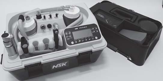
|
|
- Chester Gardner
- 5 years ago
- Views:
Transcription

1 OM-E0798E 000
2 Thank you for purchasing VIVA ace Basic Set. This product is a Portable Dental Treatment Unit used for on-site patient treatment. Please read this Operation Manual carefully before use so that you can use it safely to come through a correct use. Keep this Operation Manual within easy reach of users for future reference. Contents English English. User and Indications for Use.... Precautions for handling and operation.... Package Contents Part Names Control unit Control Panel Preparation for Use Preparation of Control Unit Connecting the Syringe Connecting the Motor Connecting the Scaler Installing the Vacuum Bottle Installing the Vacuum Hose Installing the Water Bottle Connecting the Foot control Connecting the AC Power Cord Check before treatment Operation Procedure Motor Motor <Endodontic treatment> Ultrasonic Scaler Vacuum Light Probe way Syringe When the Water Bottle is empty or the Vacuum Bottle is filled with liquid during use Sound Volume Last Memory Function Initialization Program (Factory Setting) Protection Circuit Post-use Maintenance Preparation Maintenance for Between Each Patient Maintenance After Close Sterilization Maintenance Before Use Maintenance of the Water Line Storage Procedure Transportation Maintenance Replacing the gasket (Water Bottle) Replacing the filter, gasket, O-ring (Vacuum Bottle) Replacing the O-rings (Vacuum Valve) Replacing the O-rings (Vacuum Hose) Replacing the O-ring (Vacuum Connector) Replacing the O-ring (Syringe) Replacing the fuse Drainage of Air Filter Replacing the Water Plug Periodical Maintenance Checks...5. Troubleshooting Error Code Problems and Solutions Specifications Specifications Classification of Equipment Symbol After-sales Service Warranty Spare Parts List Option Parts List Disposing product...6. EMC Information (Electromagnetic Compatibility Information)...6 Operation procedure of this product is introduced in a movie. Check the URL or the QR Code. URL * The basic function of this product is Vacuum and Syringe. Additional function is available by purchasing optional parts (VIVA ace Motor Kit, VIVA ace Scaler Kit). Refer to the attached Operation manuals for further information.
3 User and Indications for Use User : Dentist, Dental hygienist Indications for Use : The device is a dental suction system intended for dental treatment. The device is equipped with the functions of vacuum and irrigation and used by connecting motor and ultrasonic scaler. The motor is intended for teeth and denture cutting, polishing and root canal treatment. The ultrasonic scaler is intended for use in dental applications such as scaling, root canal treatment, periodontal and cavity preparation by generating ultrasonic waves. Precautions for handling and operation Please read these precautions carefully and use only as intended or instructed. Safety instructions are intended to avoid potential hazards that could result in personal injury or damage to the device. Safety instructions are classified as follows in accordance with the seriousness of the risk. Class DANGER WARNING CAUTION NOTICE Degree of Risk Hazard that could result in personal death or serious injury if the safety instructions are not correctly followed. Hazard that could result in serious injury or damage to the device if the safety instructions are not correctly followed. Hazard that could result in light or moderate injury or damage to the device if the safety instructions are not correctly followed. General product specification information highlighted to avoid product malfunction and performance reduction.
4 Precautions for handling and operation DANGER English To prevent secondary infection due to droplet/air of the Vacuum do not use these products for patients with significant infection. Do not attempt to disassemble the product nor tamper with the mechanism except as recommended by NSK in this Operation Manual. This may result in an injury, electric shock or fire. Do not handle the power cord, motor cord and scaler cord with wet hands. Wet hand contact with electricity may result in an electric shock. Do not use power cords other than genuine products made by NSK. Use of other cords may result in electric shock, fire or breakdown. Do not connect any other accessories that are not specified by NSK. Stop using the product and contact your Authorized NSK Dealer immediately if deformation, damage, or discoloration of the exterior of the control unit is observed. This may result in an electric shock and fire. If the product overheats or smells of burning, immediately turn off the power and disconnect the AC power cord. Contact your Authorized NSK Dealer. This may result in an electric shock and fire. Take care not to get water or liquid disinfectant in the control unit during use. This could cause short circuits and lead to an electric shock. Always check the Vacuum operates thoroughly and test suctioning. Adjust the suction force and the water amount according to the patient s condition. Refer to P58 - Specifications for the suction force and suction amount for the Vacuum. WARNING Do not use the product when the patient or the operator is using cardiac pacemakers as there is a danger that it may affect the pacemaker. Keep away from explosive substances and flammable materials. Also, keep away from patients whom a flammable anesthetic (eg. laughing gas) is administered as this may cause fire. Keep away from devices that generate electromagnetic waves as electromagnetic waves may cause malfunction of the product. Turn off the product around ultrasonic generators (excluding the product) or electrical scalpels. Keep away from communication equipment or elevators that generate electromagnetic waves. Do not turn the lighting of the handpiece, motor cord, or scaler cord directly to the eyes of the patients or the operators. There is a danger that this may damage the eyes. Never touch the connecting parts (the terminal parts) of the scaler handpiece, scaler cord, motor, motor cord, and control unit. This could cause an electric shock. This product is a precision instrument. During transportation of the product, do not allow any strong impact or shock to the product, or do not drop the product. This may cause product breakage, leading to an electric shock or failure. Before replacing the fuse, be sure to turn off the power switch and remove the AC Power Cord. (Reference:0-7 Replacing the fuse) If you touch the patient and the contact point inside the fuse insertion port simultaneously without taking the procedures above, it may lead to an electric shock.
5 Precautions for handling and operation CAUTION When operating the product always consider the safety of the patient. Use only as indicated. The end user shall be responsible for any judgment that relates to the application of this product to a patient. Users are responsible for the operational control, maintenance and periodical maintenance checks of this product. This device is for indoor use only. Wait before turning on and using the VIVA ace, until it has adapted to the ambient temperature (E.g. after a cold night in the car). Note the admissible operation conditions (Reference: - Specifications). Keep the product on a level surface. Do not place nor leave the product in high-temperature places such as in direct sunlight, inside a car under blazing sun, and near the heaters. This could cause discoloration and deformation. Use of the product outside its use environment and condition may cause breakdown. (Reference : - Specifications) Operators and all others in the area must wear eye protection, a mask, and gloves when operating this product. Turn off the product after using. Unplug the product when not using for a long-time period. If the product is not used for a long period, check it is functioning correctly before using on a patient. Immediately wipe off any liquid medicine, solvent, or liquid disinfection on the control unit and cords. Failure to do may cause discoloration and deformation. Hold the plug when unplugging the cords. Unplugging holding the cords may cause breaking down of the cord. Should the product function abnormally, cease operation immediately and contact your Authorized NSK Dealer. Place the product with approximately 5cm space around the product and in a position where power cords can be promptly unplugged from the power outlet in case of an emergency. Do not block the air outlets on both sides of the control unit as this may cause malfunction. The power cord is meters long. Pay attention that the operator and the patient do not carelessly step on the cord. Do not clean, immerse, or wipe with electrolyzed-oxidizing water (strong acidic water, super acidic water), strong acidic and strong alkaline liquid medicine, solvent containing chlorine, benzene, or thinner. (Reference : 7 Post-use Maintenance) Do not use tap water for the product as water tubes will get clogged with impurities in tap water. Be sure to use drinking water. The Syringe Nozzle and the Suction Tube are delivered in a non-sterile condition and must be autoclaved prior to use. Follow any additional local directives, standards, and guidelines for cleaning, disinfection, and sterilization. Perform regular function and maintenance checks. (Reference : 0-0 Periodical Maintenance Checks)
6 Precautions for handling and operation CAUTION English The use of ACCESSORIES, other than those specified by the manufacturer, may result in performance degradation of electromagnetic compatibility (EMC), increased EMISSIONS* or decreased IMMUNITY*, of the product. *: Electric noise (Mainly electromagnetic wave) *: Not to be obstructed by the electromagnetic wave generated by the electrical equipment. This product is rated Medical Electrical equipment. EMC (Electromagnetic compatibility) is described in the documentation included. Installation and use of this product requires special precautions regarding EMC according to the EMC information. Portable and mobile RF communications equipment can affect Medical Electrical equipment. Do not use RF equipment near the product. This product should not be used adjacent to, or stacked with, other equipment. If adjacent or stacked use is necessary, this product should be observed to verify normal operation in the configuration in which it will be used. NOTICE Before the first use of the product, check the operation and storage of the product. Perform an operation check before visiting treatment. The compressor will be turned on when turning on the power and during idling to maintain the setting pressure. This is not a failure. When idling, the Vacuum constantly performs weak suction. This is not a breakdown. Contact your Authorized NSK Dealer for repairing. The service staff of the company will take care of the product in accordance with the service manual. No special training is required for this device. For the cautions, operation procedures and the maintenance of the optional products; VIVA ace Motor Kit, VIVA ace Scaler Kit, refer to the Operation Manual attached to each product. This product cannot connect an amalgam separator to the disposal system. When performing amalgam filling/removing, use a suction device with amalgam separation function. 5
7 Package Contents 6
8 Package Contents English No. Part Name Order Code Quantity Remarks Top Case Cover - - AC Power Cord U Top Case - - Foot Control Z FC-70S (For Vacuum) 5 Foot Control Z08005 FC-76S (For Motor and Scaler) 6 Vacuum Bottle Set U Vacuum Cap A U750 White, Convex shape 8 Vacuum Cap B U75 White, Concave shape 9 Water Bottle Set U Control Unit - - way Syringe - - way Syringe Nozzle U06 Sterilizable Vacuum Junction Hose U75 - Vacuum Hose U076-5 Hose Cap U75 Black 6 Vacuum Valve U079-7 Suction Tube - 0 Sterilizable 8 Spanner Z09-9 Shoulder Belt U70 With a pad 0 Cleaning Adaptor U097 - Quick Operation Guide - *Not in the illustration. Operation Manual - *Not in the illustration. Please specify the order code listed above when ordering the spare parts. Other spare parts are listed on Page 60. (Reference : - Spare Parts List) 7
9 Part Names - Control Unit Water Plug (OUT) [Blue Tube] Water Plug (IN) [Clear Tube] Syringe Water Adjuster Vacuum Connector Motor Water Adjuster Scaler Water Adjuster Syringe Connector Scaler Connector Motor Connector Control Panel Buckle ( Places) Holder Bar Holder Arm Lock Holder Holder Bar Lock Holder Arm 8
10 Part Names English Power Switch Fuse Holder Power Inlet Foot Control Connector (For Vacuum) Foot Control Connector (For Motor/Scaler) Outlet (For internal cooling) *The outlet on the other side is for Vacuum Handle Latch ( Places) Belt Hook ( Places, For Shoulder Belt) Shoulder Belt 9
11 Part Names - Control Panel Keys of the Control Panel Liquid Crystal Display of the Control Panel *The illustration above shows all the marks. NOTICE A protective sheet is applied on the liquid crystal display to prevent flaws during shipping. Remove the sheet before using the product. When removing the sheet, minor change on the liquid crystal display may be noticed. It will soon get back to normal. This is not a failure. 0
12 Part Names No. Key Name Display Function MOTOR Key Selecting the suitable mode and the gear ratio (:, :5) for general cutting and tooth surface cleaning. English ENDO Key Selecting the suitable mode for root canal treatment. LIGHT PROBE Key Selecting Light Probe Mode SCALER Key Motor/Scaler ON/OFF Key MEMORY Key AUTO REV Key FWD/REV Key LIGHT Key SPRAY Key VACUUM Key VACUUM ON/OFF Key Selecting Ultrasonic Scaler At the same time, selecting the Treatment Mode (P, E, G) (P : PERIO Mode, E : ENDO Mode, G : GENERAL Mode) Switching ON/OFF of Motor and Scaler Operation. It stores five setting programs (speed, torque, and auto reverse setting) during ENDO Mode. (Reference : 6- Motor <Endodontic treatment>) Setting and cancellation of auto reverse function during the ENDO Mode AUTO REVERSE FORWARD AUTO REVERSE AUTO STOP (Reference : 6- Motor <Endodontic treatment>) Selecting the direction of rotation during MOTOR, ENDO Mode Forward Rotation Reverse Rotation (Clockwise rotation) (Counter Clockwise rotation) Selecting ON/OFF of lighting during MOTOR and ENDO, Light Probe Mode Selecting ON/OFF of Water Pouring functions during MOTOR, ENDO, and SCALER Mode. Selecting the Vacuum suction power in three levels. Selecting Linking/Unlinking of the Vacuum with Motor and Scaler (Linking : Sync, Unlinking : No display) ON/OFF of the Vacuum function During the ENDO Mode Torque Setting (0. -.0N cm) TORQUE Key During the SCALER Mode Power Setting ( - 0) When selecting the Light Probe Mode Sound Volume Setting (High/Low/Silent) During the MOTOR Mode Speed Setting SPEED Key During the ENDO Mode Speed Setting When selecting the Light Probe Mode Light Quantity Setting
13 5 Preparation for Use 5- Preparation of Control Unit Open the Latch at the left and right of the Top Case Cover and take the Top Cover Case off. Take out the AC Power Cord and Foot Control (FC-76S, FC-70S). Unlock the buckles on the front and back of the Control Unit and remove the Top Case from the Control Unit. 5 Take out the Water Bottle Set and the Vacuum Bottle Set. Pull down the Holder Bar Lock and stretch the Holder Bar upward. 5 Holder Bar Lock 6 Holder Arm Lock 6 Press the Holder Arm Lock and turn the holder forward. The position can be set at four points. 7 7 Face the holder forward so that it is easy to place the handpieces. CAUTION Do not hold the Top Case Cover Latch when carrying the Control Unit. There is a risk that the Control Unit would fall as shown in the illustration, and cause injuries or breakage. The Latch is for taking off/putting on the Top Cover Case, not for carrying.
14 Preparation for use CAUTION English Be careful not to get fingers caught when turning the holder while pressing the Holder Arm Lock. It may cause injuries. The holder cannot be turned to the direction shown in the illustration. Turning by force could cause breakage and deformation. Do not put excessive load to the holder to prevent from breaking down and deformation. 5- Connecting the Syringe 5 Aligning the mark of the syringe hose plug and the shape of the terminal as shown below, insert the plug deep into the syringe connector. Turn the Plug Cover for tightening. Insert the syringe nozzle firmly until a clicking sound is heard. *The syringe nozzle has already been inserted at the shipping. Move on to the next step. Pull and push the syringe nozzle to confirm it is surely connected. Place the Syringe on the Holder. *For easy handling, avoid pushing in the syringe when placing. mark 5 Loosen Tighten CAUTION Be sure to tighten the plug cover firmly. If tightening is insufficient, water and air will leak and the compressor will not stop. If the syringe nozzle comes out easily when connecting to the syringe, stop operating and replace the O-rings.Continuous use of the syringe nozzle in the above conditions could cause the nozzle to stick out. (Reference: 0-6 Replacing the O-ring (Syringe) )
15 Preparation for use 5- Connecting the Motor * VIVA ace Motor Kit (Optional) Aligning the hole on the back of the Motor and the pin on the Motor Cord Connector, insert the pin straight into the hole and tighten the Motor Cord Nut firmly. Aligning the mark of the Motor Cord Plug and the shape of the terminal as shown below, insert the Plug deep into the motor connector. Turn the Plug Cover to tighten. Hole mark Motor Motor Cord Connector Tighten Loosen Motor Cord Nut Loosen Pin Tighten Place the Motor on the holder. 5- Connecting the Scaler * VIVA ace Scaler Kit (Optional) Aligning the mark of the scaler cord and the shape of the terminal as shown below, insert the cord deep into the scaler connector. mark Loosen Tighten Turn the Plug Cover to tighten. Place the Scaler Cord Plug on the Holder.
16 Preparation for use 5-5 Installing the Vacuum Bottle English Remove the Vacuum Cap A/B. Remove the Vacuum Bottle Lid and confirm that there is no foreign substance inside. Vacuum Cap A Vacuum Cap B Loosen Aligning the filter guide pin and the notch of the filter, insert the filter until it meets the end. *The filter has already been inserted at the shipping. Move on to the next step. Filter Guide Notch Float Spindle Check that the float spindle moves smoothly and it does not stick to the lid. Pin Filter 5 Tightly close the Vacuum Bottle lid Confirm again that the float spindle is not stuck to the lid and in the state of. If it is in the state of, press the top. Tighten 7 Place the Vacuum Bottle in the Control Unit. 7 8 Vacuum Junction Hose 8 Insert the Vacuum Junction Hose to the Vacuum Connector firmly. Vacuum Connector CAUTION Do not operate the Vacuum without the filter as sucked liquid (saliva, blood, etc.) will stick to the float spindle and prevent the float spindle from moving. This may cause the sucked liquid to enter the control unit and result in abnormal smell and breakage. Incomplete connection may result in lowering the suction power. 5
17 Preparation for use 5-6 Installing the Vacuum Hose Remove the Hose Cap and insert the Vacuum Hose to the Vacuum Bottle Lid until it meets the end. Vacuum Hose Insert the Vacuum Valve to the Vacuum Hose until it meets the end. *The Vacuum Valve has already been inserted at the shipping. Insert the Suction Tube to the Vacuum Valve until it meets the end. Place the Vacuum on the Holder. CAUTION Incomplete connection may cause the leakage of sucked liquid (saliva, blood, etc.) 5-7 Installing the Water Bottle Remove the Water Bottle lid and check that there is no foreign substance inside. Fill with drinking water until it reaches below the maximum line (50 ml). Maximum line Tightly close the Water Bottle lid and place the Water Bottle in the Control Unit. Insert the Water Plug (OUT) [Blue Tube] and the Water Plug (IN) [Clear Tube] to the lid until hearing a clicking sound. Water Plug (OUT) [Blue Tube] Water Plug (IN) [Clear Tube] Tighten 6
18 Preparation for use CAUTION Be sure to use drinking water only. Use of Saline, liquid medicine, high acid water may cause a failure. Incomplete installation may cause leakage of air and water. Do not place the Water Bottle anywhere other than the designated place as this may cause water leakage. Be sure to tighten the bottle lid firmly. If it is loose, the air will leak and the compressor will not stop. Do not tilt or set the bottle down with water inside. The water may be spilled. English 5-8 Connecting the Foot Control Aligning the mark as shown below, insert the FC-76S Foot Control Plug (Black) into the Connector on the right until it meets the end. mark mark Aligning the mark as shown below, insert the FC-70S Foot Control Plug (White) into the Connector on the left until it meets the end. 5-9 Connecting the AC Power Cord After checking that all the accessories have been connected, confirm that the Power Switch is OFF ( side). Insert the AC Power Cord into the inlet until it meets the end, and then insert it to the commercial power outlet. 7
19 Preparation for use 5-0 Check before treatment Perform the following checks before using the product on a patient to confirm that there are no abnormalities. If abnormal vibration, noise, or overheating is detected, stop using the product and contact your Authorized NSK Dealer. CAUTION Wait before turning on and using the VIVA ace, until it has adapted to the ambient temperature (E.g. after a cold night in the car). Note the admissible operation conditions (Reference: - Specifications). If the power switch is turned on without connecting the syringe to the control unit, water and air will blow out from the syringe connector. Be sure to turn on the power switch after connecting. No. Action Check that there is no abnormal deformation or damage in the appearance. Supply drinking water into the Water Bottle. Confirm that all the accessories are properly connected. Turn the Power Switch ON (l side), and confirm that the product is in the state of stand-by as defined below. The compressor is activated and stops after a few seconds. The liquid crystal display of the control panel lights and notification sound rings Start the Vacuum and confirm that it vacuums. Activate the Syringe for about 5 seconds by pressing both the air button and the water button. If VIVA ace Motor Kit (optional) is connected, connect the handpieces to the motor, attach the bur, and then activate the motor for about 0 seconds while applying water. Also, confirm the points below. Check if there is any abnormal vibration, noise or overheating. Check that the handpiece supplies water properly. Check that the light on the motor is on. If VIVA ace Scaler Kit (optional) is connected, connect the handpieces to the scaler cord plug, attach the tip, and then activate the scaler for about 0 seconds while applying water. Also, confirm the points below. Check that the tip is vibrating properly. Check if there is any abnormal looseness, vibration, noise, or overheating with the tip. Check that the tip supplies water properly. Check that the light on the handpiece is on. 8
20 6 Operation Procedure 6- Motor English Select the gear ratio Set the speed Gear Ratio Speed (min - ) :5 5,000-00,000 :,000-0,000 Interval (min - ) 5,000,000 *When the motor is running, it displays the actual speed. When the motor is not running, it displays the maximum set speed. *The speed can be continuously changed during operation. (The value increases/decreases by holding down the button.) 5 7 Select the direction of rotation Forward Rotation Reverse Rotation *This can be switched during operation. Activate/Stop the Motor Two ways to activate/stop the Motor are shown below: Light ON/OFF For light quantity setting, refer to 6-5 Light Probe 6 Water ON/OFF For Vacuum function, refer to 6- Vacuum Motor Water Adjustment When using FC-76S Foot Control Step on the pedal Release the pedal *The speed can be controlled by the stepping-in pressure when using FC-76S Foot Control. Activate Stop Manually Operation ON/OFF Press more than seconds *Long press works only for ON The water amount can be adjusted by turning the knob. *This can be adjusted during operation CAUTION Operating without connecting the Motor will cause the Motor Connector to blow out water and air. 9
21 Operation Procedure 6- Motor <Endodontic treatment> Change to ENDO Mode Speed Setting Speed (min - ) 00 -,000 Interval (min - ) 50,000-5, *When the motor is running, it displays the actual speed. When the motor is not running, it displays the maximum set speed. *The speed can be continuously changed during operation. (The value increases/decreases by holding down the button.) Select the program 5 programs can be stored. Select Auto Reverse function Select the direction of rotation Forward Rotation Reverse Rotation *This can be switched during operation Activate/Stop the Motor Two ways to activate/stop the Motor are shown below: When using FC-76S Foot Control Step on the pedal Release the pedal *The speed can be controlled by the stepping-in amount when using FC-76S Foot Control. Activate Stop 7 Light ON/OFF For light quantity setting, refer to 6-5 Light Probe Manually Operation ON/OFF Press more than seconds * Long press works only for ON 9 8 Torque Setting Torque Setting : N cm *Interval : 0. N cm Water ON/OFF For Vacuum function, refer to 6- Vacuum Motor Water Adjustment The water amount can be adjusted by turning the knob. *This can be adjusted during operation <Memory Function> Various settings (speed, torque, and auto reverse setting) can be saved to a memory number by pressing the Memory Key. 5 programs can be stored during the ENDO Mode.. Press the MEMORY Key to show the number that is wished to be stored.. Select various setting (speed, torque, and auto reverse setting).. Long press the MEMORY Key for more than second, the storing is finished when the notification sound rings. NOTICE The Memory function does not work when the direction of rotation is set R: Reverse Rotation. 0
22 Operation Procedure <Auto Reverse Function> The following rotation modes can be selected when the load reaches the torque setting value during the ENDO Mode. English AUTO REVERSE FORWARD Stops when the load reaches the torque setting value, starts reverse rotation, and when the load is removed, it automatically goes back to forward rotation. Load with in the torque setting value Forward Rotation Load above the torque setting value Reverse Rotation When the load continues, it keeps Reverse Rotation. When the load is removed, it goes back to Forward Rotation. Forward Rotation AUTO REVERSE When the load reaches the torque setting value, it stops and starts reverse rotation. When the load is removed, it continues reverse rotation. Load with in the torque setting value. Load above the torque setting value Although the load is removed, it continues reverse rotation. Forward Rotation Reverse Rotation Reverse Rotation AUTO STOP Stops when the load reaches the torque setting value. When you wish to start the rotation (forward rotation) again, press the ON/OFF Key or step on the Foot Control. NOTICE When the direction of rotation is set Reverse Rotation, Auto Reverse Function does not work. When the load is continuously placed on the motor, it sometimes stops automatically in the purpose of protecting from heat. When this happens, leave the motor for a while for cooling.
23 Operation Procedure 6- Ultrasonic Scaler Select the treatment mode P : PERIO Mode E : ENDO Mode G : GENERAL Mode Power Setting to 0 *Set it below the maximum power of the tip. *The power can be changed during operation. (The value continuously increases/decreases by holding down the button.) 5 Activate/Stop the Scaler Two ways to activate/stop the Scaler are shown below. When using FC-76S Foot Control Water ON/OFF Manual Operation ON/OFF For Vacuum function, refer to 6- Vacuum Scaler Water Adjustments Step on the pedal Release the pedal Activate Stop Press more than seconds *Long press works only for ON The water amount can be adjusted by turning the knob. *This can be adjusted during operation <Examples> PERIO Mode : Power 8 ENDO Mode : Power 6 GENERAL Mode : Power CAUTION Operating without connecting the Scaler to the product causes the Scaler Connector to blow out water.
24 Operation Procedure 6- Vacuum English Select the suction force Weak/Medium/Strong Activate/Stop the Vacuum Two ways to activate/stop the Vacuum are shown below. When using FC-70S Foot Control Vacuum ON/OFF During treatment Suctioning stops by closing the Vacuum Valve Lever. Vacuum Valve Lever Open Close Step on the pedal Release the pedal Manual Operation ON/OFF Activate Stop Sync Mode (Synchro Mode) The Vacuum can be synchronized with the Motor and the Scaler (except during Light Probe Mode). It can be set individually at each Mode (MOTOR, ENDO, and SCALER), however the suction force value will remain the same. Long press the VACUUM Key (More than second) Linked Not Linked When the motor and the scaler are activated, the Vacuum will be activated in conjunction. DANGER Always check the Vacuum operates properly and perform suctioning accordingly. Adjust the suction force and the water amount according to the patient s condition. Refer to P58 - Specifications for the suction force and suction amount for the Vacuum.
25 Operation Procedure NOTICE Do not suck exceeding the maximum line (00 ml) of the Vacuum Bottle. Sucked liquid (saliva, blood, etc.) may get into the Control Unit and cause abnormal smell or malfunction. When the device is operating normally, the Float Spindle controls the suctioning to prevent over suctioning. Note that there is a risk that the float spindle may not work and over suctioning may occur in the case of abnormality. The device should be placed on the level surface. If not, there is a risk that the sucked liquid may enter the Control Unit even when the device is operating normally and the float spindle is working. Do not tilt or set the Vacuum Bottle down with sucked liquid inside. The liquid may be spilled. The Vacuum cannot be operated in other ways during the Sync Mode. The Vacuum stops a few seconds after the Motor and the Scaler stop. 6-5 Light Probe Connect the Light Probe Connect the isoe-lux to the Motor Light Quantity Setting Adjustments can be made in increments and is directly reflected in the light quantity of the MOTOR Mode Select the Light Probe Mode The light is automatically turned on. Light ON/OFF 6-6 way Syringe Syringe Water Adjustment Syringe ON/OFF Water Button Water comes out when pressed Air Button Air comes out when pressed. The water amount can be adjusted by turning the knob. *This can be adjusted during operation Pressing the both buttons at the same time provides spray water.
26 Operation Procedure WARNING English Pay close attention when blowing air from the syringe nozzle toward the patient's gingiva because procedural accidents such as subcutaneous emphysema could be caused. If any abnormality is detected, stop using the product and take appropriate procedures. NOTICE If the Air Button is pressed while residual water is inside the Syringe Nozzle, the water will be mixed in the supplied air. Before you use air supply only, gently shake the Syringe while pressing the Air Button to thoroughly drain the residual water inside the Syringe Nozzle. 6-7 When the Water Bottle is empty or the Vacuum Bottle is filled with liquid during use Turn off the Power Switch ( side). Dispose of the sucked liquid (saliva, blood, etc.) in the Vacuum Bottle. (Reference: 7-- Cleaning (Vacuum Hose)) Remove the Water Bottle and fill it with water. NOTICE When removing the Water Bottle, be sure to remove the Water Plug (IN) [Clear Tube] first. Note that if the Water Plug (OUT) [Blue Tube] is removed first, the water in the bottle will blow out for a moment. (Reference: 7- Preparation) When the Water Bottle (IN) [Clear Tube] is removed, the air in the bottle bursts out and makes a noise. This is not a failure. 5
27 Operation Procedure 6-8 Sound Volume Sound volume of Key Operation and notification tone can be set. Press the LIGHT PROBE Key Sound Volume Setting Volume : High Volume : Low Volume : Partly OFF* *Sound which rings around the torque setting value and during the auto reverse operation during the ENDO mode are OFF <Types of sound> No. Type Sound When turning on the Power Switch short beep When pressing each key short beep When long pressing the SPEED Key and the TORQUE Key short beep followed by successive short beeps while the key is being pressed When storing short beep followed by long 5 6 When reaching the maximum/minimum value, When operation is not possible When reaching 50% of the torque setting value. short beeps Melody 7 ENDO Mode When reaching 80% of the torque setting value Melody 8 When auto reversing Melody 9 When an error is detected long beep NOTICE The sound volume setting is saved after turning off the device. 6
28 Operation Procedure 6-9 Last Memory Function English About setting of the each mode after the Main Power was turned off. In case of each mode (MOTOR, ENDO, SCALER, LIGHT PROBE): -The setting will be back to an initial state, when turning on the Main power. In case of light quantity, sound volume, and the Vacuum suction force: -The last settings are saved. NOTICE Settings other than the setting of light quantity, sound volume and the Vacuum suction force, go back to default every time the device is turned on. 6-0 Initialization Program (Factory Setting) The setting can be restored to the Factory Settings. Turn off the Power Switch. Turn on the Power Switch while pressing the MEMORY Key. When a beep sound rings, initialization is finished. <Factory Settings> Mode Speed (min - ) Torque (N cm) Power Mode Water Light ON/OFF Direction of Rotation Auto Reverse Mode Vacuum suction force Sound Volume MOTOR,000 (Gear Ratio : ) - - OFF ON F : Forward rotation - ENDO 00 *All memories together 0. *All memories together SCALER OFF ON F : Forward rotation Power : Mode : P AUTO REVERSE FORWARD ON Strong High LIGHT PROBE ON - - NOTICE Take note of present settings before initialization if needed. The setting of light quantity before initialization is kept. 7
29 Operation Procedure 6- Protection Circuit The protection circuit will be activated and stop the device to prevent from danger and breakage when the device is operated with the load exceeding its maximum value. The error code will be displayed in the display panel. (Reference:- Error Code) <Motor> The Motor will stop automatically due to failure, excessive load, disconnection and incorrect usage of the device. Protection function will work and control the torque automatically to prevent the overheating of Motor Coil caused by excessive load. flickers on the occasion. When the protection function is released, the torque will automatically recover. During the MOTOR Mode, turns off, and during the ENDO Mode, stops flickering. <Scaler> When using exceeding the power 7 of the G Mode, and the inside being heated by long-time use, protection function will be activated and lower the power automatically. flickers on the occasion. When protection function is released, flickering will be turned off. However, the power will not automatically go up over 8 for safety reasons. Increase the power manually when needed. NOTICE <Scaler> While the protection function is working, ( flickering) it is not possible to higher the power over 7. 8
30 7 Post-use Maintenance After each patient maintain the product as follows. 7- Preparation English Wear eye protection, a mask, and gloves to prevent infection. Turn off the Power Switch of the Control Unit. First, remove the Water Plug (IN) [Clear Tube] while pulling the Slide Ring. Remove the Water Plug (OUT) [Blue Tube] pressing the Slide Ring. Dispose of the water in the Water Bottle and set the empty bottle again in the Control Unit. Turn on the Power Switch of the Control Unit. Maximize each Water Adjuster, activate the Motor, Scaler and the Syringe to let out the water remaining in the hose. Activate the Vacuum. Hold the Vacuum Hose above the bottle to let the sucked liquid flow into the bottle. Water Plug (IN) [Clear Tube] Slide Ring CAUTION Do not clean, immerse, or wipe with electrolyzed-oxidizing water (strong acidic water, super acidic water), strong acidic and strong alkaline liquid medicine, solvent containing chlorine, benzene, or thinner. Do not wash the product with a thermo-disinfector. It may result in failure. Maintain the vacuum hose, bottles, and other accessories properly. Store and keep the product dried. Insufficient maintenance and drying could cause abnormal smell and rust. Be sure to check if there is residual water inside the product (bottles, cords and hoses). If water remains, it may freeze and cause breakage. For details of the cleaning, disinfectant, etc. used for the "VIVAace", confirm the the operation manuals issued by manufacturer. Do not use a cleaning and disinfection solution etc. not mentioned in this operation manual. Follow any additional local directives, standards, and guidelines for cleaning, disinfection, and sterilization. Option parts (Motor and Ultrasonic Scaler) should be maintained in accordance with the attached operation manuals. NOTICE Be sure to remove the Water Plug (IN) [Clear Tube] first. Note that if the Water Plug (OUT) [Blue Tube] is removed first, the water in the bottle may blow out for a moment. When the Water Plug (IN) [Clear Tube] is removed, the air in the bottle bursts out and makes a noise. However, this is not a failure. 9
31 Post-use Maintenance 7- Maintenance for between each patient 7-- Cleaning (Vacuum Hose) Remove the Vacuum Bottle from the Control Unit with the Vacuum Hose attached. Remove the Vacuum Hose and the Vacuum Bottle Lid, then dispose of the sucked liquid (saliva, blood, etc.) in the bottle. Vacuum Valve Lever Close Remove Remove Attach the Vacuum Bottle Lid and the Vacuum Hose to the Vacuum Bottle and place it in the Control Unit. Remove the Suction Tube, connect the Cleaning Adaptor to the Vacuum Valve, and then connect the Suction Tube again., 7 Cleaning Adaptor Suck the drinking water (amount of about 00mL) to clean the hose. Dispose of the sucked water in the Vacuum bottle (Repeat procedure No. to.). Wipe the surface of the Vacuum Hose, Vacuum Bottle, Cleaning Adaptor and the Holder with the disinfectant wipes (Minuten Wipes: ALPRO). Tightly close the Vacuum Bottle Lit and attach the Vacuum Hose to the Vacuum Bottle. Then place the Vacuum Bottle in the Control Unit. Attach the sterilized Suction Tube to the Vacuum Valve. Tighten Tighten Minuten Wipes (ALPRO) 9 Place the Vacuum on the Holder. CAUTION Change to a sterilized Suction Tube after each patient (Suction Tube can be sterilized). NOTICE If the Vacuum Valve Lever is not closed, there is a danger that the sucked liquid remaining in the Vacuum Hose might run out. The removal of the Vacuum Hose from the Vacuum Bottle should be done in the cleaning tank because there might be sucked liquid (saliva, blood, etc.) remaining in the Vacuum Hose. 0
32 Operation Procedure 7-- Cleaning and Disinfection of the outside of the Motor and the Motor Cord, and Replacing the Motor English <Cleaning> Remove the all debris on the surface of the Handipiece, Motor and the Motor Cord with a wipes (Minuten Wipes: ALPRO). Remove the bur from the Handpiece with tweezers. * Maintenance of the bur should be done in accordance with the operation manual issued by the manufacturer. Remove the Handpiece from the Motor. * Maintenance of the Handpiece should be done in accordance with its operation manual. Wipe the debris on the surface of the Motor and the Motor Cord using a cloth moistened with water. Under appropriate lighting (500 lx or higher), inspect the Motor and the Motor cord for contamination. 5 If any visible contamination remains, repeat the process until it is visually clean. Be sure to repeat from the procedure No.. <Disinfection> Wipe the surface of the Motor, the Motor Cord and the Holder with the disinfectant wipes (Minuten Wipes: ALPRO). Disconnect the Motor from the Motor Cord, then attach a sterilized Motor and place it on the Holder. * Be sure to sterilize a used Motor. Reference: "7- Sterilization". Minuten Wipes (ALPRO) lx Minuten Wipes (ALPRO) 7-- Cleaning and Disinfection of outside of the Scaler Handpiece and the Scaler Cord, and Replacing the Scaler Handpiece <Cleaning> Remove the all debris on the surface of the Scaler Handpiece and the Scaler Cord using the wipes (Minuten Wipes: ALPRO). Remove the Tip from the Scaler Handpiece * Reference: "- Mounting the Tip" of the Scaler Kit Operation Manual. Wipe the debris on the surface of the Scaler Handpice and the Scaler Cord with a cloth moistened with water. Under appropriate lighting (500 lx or higher), inspect the Scaler Handpiece and the Scaler Cord for contamination. If any visible contamination remains, repeat the process until it is visually clean. Be sure to repeat from the procedure No.. Minuten Wipes (ALPRO) 500 lx 500 lx
33 Post-use Maintenance 7-- Cleaning and Disinfection of outside of the Scaler Handpiece and the Scaler Cord, and Replacing the Scaler Handpiece (continued) <Disinfection> Wipe the surface of the Scaler Handpiece and the Scaler Cord with the disinfectant wipes (Minuten Wipes: ALPRO). Disconnect the Scaler Handpiece from the Scaler Cord, then attach a sterilized Scaler Handpiece and place it on the Holder. * Be sure to clean, disinfect and sterilize a used Scaler Handpiece and the Tip. Reference: Scaler Kit Operation Manual. Minuten Wipes (ALPRO) 7-- Cleaning (Syringe) and Replacing of the Syringe Nozzle <Cleaning> Remove the Syringe Nozzle from the Syringe Body. Syringe Body: Proceed to the procedure No. Syringe Nozzle: Proceed to the "7--9 Cleaning and Disinfection (Syringe, Syringe Nozzle)". Remove the debris on the surface of the Syringe Body with a plastic brush (do not use the wire brush.). Wipe the Syringe Body with a cloth moistened with water. After cleaning, under appropriate lighting (500 lx or higher), inspect the Syringe Body for contamination. If any visible contamination remains, repeat the process until it is visually clean. Be sure to repeat from the procedure No.. <Disinfection> Wipe the surface of the Syringe Body with the disinfectant wipes (Minuten Wipes: ALPRO). Attach a sterilized Syringe Nozzle to the Syringe Body and place it on the Holder. * Be sure to sterilize a used Syringe Nozzle, refer to section "7- Sterilization". 500 lx Minuten Wipes (ALPRO) 7--5 Cleaning (Control Unit etc.) Action Objects: Control Unit, Top Case, Top Cover Case, Shoulder Belt, Spanner. Turn off the power switch of the Control Unit and take out all the accessories. After wiping the water with wrung out cloth, wipe with the disinfectant wipes (Minuten Wipes: ALPRO). Fig.
34 Post-use Maintenance 7- Maintenance After Close English 7-- Cleaning (Vacuum Hose, Vacuum Bottle) Turn off the Power Switch of the Control Unit. Close the Vacuum Valve Lever. Vacuum Valve Lever Close Remove Remove Remove the Vacuum Junction Hose at the Vacuum Bottle side only. Remove the Vacuum Bottle from the Control Unit with the Vacuum Hose attached Remove the Vacuum Hose by twisting and pulling up the hose. Loosen 6 7 Remove the Vacuum Bottle lid and dispose of the sucked liquid (saliva, blood, etc.) in the bottle. Remove the filter from the lid. 7 Filter 8 Guide Remove the guide from the lid. Remove the Gasket (Black) and the Gasket with tweezers. Open the Vacuum Valve Lever. 9 Gasket (Black) Gasket (thickness mm) 0 Vacuum Valve Lever Open Clean the solid matter attached to the Filter, the Float Spindle, and the Vacuum Hose with running water. * For the remaining dirt, use a brush (Do not use a wire brush) to remove the dirt. Clean the outside and the inside of the Vacuum Bottle with running water. * For the remaining dirt, use a brush (Do not use a wire brush.) to remove the dirt. NOTICE If the Vacuum Valve Lever is not closed, there is a risk of the sucked liquid remaining in the vacuum hose might flow backward. The removal of the Vacuum Hose should be done in the cleaning tank because there might be sucked liquid (saliva, blood, etc.) remaining in the Vacuum Hose.
35 Post-use Maintenance 7-- Cleaning (Vacuum Hose, Vacuum Bottle) (Continued) Wipe the water on the outside of each part with a wrung out cloth. Wipe with the disinfectant wipes (Minuten Wipes: ALPRO). Wrung out cloth Minuten Wipes (ALPRO) 5 Attach the Gasket to the Vacuum Bottle Lid. 5 Gasket (thickness mm) 6 Gasket (Black) 6 Attach the Gasket (Black) to the Vacuum Bottle Lid. 7 Attach the Guide to the Lid. Do not attach the Filter at this time. 7 8 Guide 8 Put the Lid back on to the bottle and connect the Vacuum Hose to the Lid. Tighten 9 Set the Vacuum Bottle in the Control Unit and connect the Vacuum Junction Hose. 9 0 Cleaning Adaptor 0 Remove the Suction Tube, connect the Cleaning Adaptor to the Vacuum Valve, and then connect the Suction Tube again. 7-- Disinfection (Vacuum Hose, Vacuum Bottle) Prepare a container of 500 ml capacity, and make 50 ml Disinfectant solution. * For details, confirm the operation manual isseued by manufacturer. Disinfectant solution: AlproJet-DD (5 ml): ALPRO Dilution Ratio: % Turn on the Power Switch of the Control Unit. Diluted Disinfectant Solution 50 ml Activate the vacuum, suck the disinfection solution until the container is empty. * Vacuuming will stop automatically when the sucking amount exceeds the maximum amount.
36 Post-use Maintenance Close the Vacuum Valve Lever. Stop VACUUM and then turn off the Power Switch of the Control Unit. Remove the Vacuum Junction Hose from the Vacuum Bottle side only. Remove the Vacuum Bottle from the Control Unit with the Vacuum Hose attached. Remove the Vacuum Hose by twisting and pulling up the Vacuum Hose. Remove the Vacuum Bottle Lid and dispose the sucked disinfectant solution of the inside of the bottle. Open the Vacuum Valve Lever. 6 7 Vacuum Valve Lever 8 0 Vacuum Valve Lever Close 9 Loosen Cleaning Adaptor Remove English Remove the Suction Tube and the Cleaning Adaptor. 5 Clean the Vacuum Hose, Vacuum Bottle, Suction Tube, Vacuum Valve, and the Cleaning Adaptor under running water. Wipe the water on the surface of the Vacuum Hose, Vacuum Bottle, Suction Tube, Vacuum Valve and the Cleaning Adaptor with a wrung out cloth. Remove the Guide from the Lid. Remove the Gasket (Black) and the Gasket with tweezers. 5 Gasket (Black) Gasket (thickness mm) 6 Guide 6 7 Prepare an empty container and make the Disinfectant Solution. *For details, confirm the operation manual issued by manufacturer. Disinfectant solution: AlproJet-DD (ALPRO) Dilution Ratio: % Soak the Guide, Lid, Gasket (black), Gasket (Thickness mm), Filter, Vacuum Cap A/B, Hose Cap, Vacuum Bottle, Vacuum Hose, Suction Tube and Cleaning Adaptor in the Disinfectant Solution for a night. 7 Diluted Disinfectant solution CAUTION Do not attach the Filter to the Vacuum Bottle Lid, when disinfecting the Vacuum Hose and the Vacuum Bottle with the Alpro Jet-DD (ALPRO). NOTICE If the Vacuum Valve Lever is not closed, there is a danger that the disinfectant solution remaining in the Vacuum hose might flow backward. 5
37 Post-use Maintenance 7-- Cleaning (Water Bottle) Remove the Water Bottle Lid. Clean the inside and the outside of the Water Bottle and the Lid under running water. * For the remaining dirt, use a soft bristled brush to remove the dirt. * Make sure that no dir t is remaining af ter cleaning. When there is remaining dirt, repeat the cleaning procedure until dirt is completely cleaned away. Loosen After wiping with a dry cloth, wipe with the disinfectant wipes (Minuten Wipes: ALPRO) and set up the bottle. Minuten Wipes (ALPRO) 7-- Cleaning and Disinfection of the outside of the Motor and the Motor Cord <Cleaning> Remove the all debris on the surface of the Handipiece, Motor and the Motor Cord with a wipes (Minuten Wipes: ALPRO). Remove the bur from the Handpiece with tweezers. * Maintenance of the bur should be done in accordance with the operation manual issued by the manufacturer. Remove the Handpiece from the Motor. * Maintenance of the Handpiece should be done in accordance with its operation manual. Wipe the debris on the surface of the Motor and the Motor Cord with a cloth moistened with water. Under appropriate lighting (500 lx or higher), inspect the Motor and the Motor cord for contamination. 5 If any visible contamination remains, repeat the process until it is visually clean. Be sure to repeat from the procedure No.. <Disinfection> Wipe the surface of the Motor, the Motor Cord and the Holder with disinfectant wipes (Minuten Wipes: ALPRO). Minuten Wipes (ALPRO) lx Disconnect the Motor from the Motor Cord. Motor Cord: Place the Holder. Motor: Proceed to section "7- Sterilization". Minuten Wipes (ALPRO) 6
38 Post-use Maintenance 7--5 Cleaning of the outside of the Scaler Handpiece English <Cleaning> Remove the all debris on the surface of the Scaler Handpiece and the Scaler Cord with the wipes (Minuten Wipes: ALPRO). Remove the Tip from the Scaler Handpiece. Remove the Scaler Handpiece from the Scaler Cord. * Reference "- Mounting the Tip" of the Scaler Kit Operation Manual. * Maintenance of the Tip and the Tip Wrench, refer to the Scaler Kit Operation Manual. Clean the surface of the Scaler Handpiece under running water with a soft bristled brush for more than 0 seconds. 5 Water temperature: 8C or less Water quality: Water available as drinking water Water amount:.5l/min or more Wipe the residual moisture on the surface of the Scaler Handpiece with a dry cloth. After cleaning, under appropriate lighting (500 lx or higher), inspect the Scaler Handpiece for contamination. If any visible contamination remains, repeat the process until it is visually clean. Be sure to repeat from the procedure No.. Minuten Wipes (ALPRO) lx 7--6 Cleaning and Disinfection of the inside of the Scaler Handpiece (Including the Water Line) CAUTION Be sure to perform Cleaning and Disinfection the "7--5 Cleaning of the outside of the Scaler Handpiece" before "7--6 Cleaning and Disinfection of the inside of the Scaler Handpiece (Including the Water Line)" After disinfection, be sure to sterilize the Scaler Handpiece. Reference: "7- Sterilization". When using the each Spray (ALPRO), be sure to cover the tip of the Scaler Handpiece with a cloth, etc. to prevent the dispersal of the cleaning solution and the disinfecting solution in the surrounding area. It is recommended to use a Spray Mist Absorber (Y90008). 7
39 Post-use Maintenance Manual Cleaning and Disinfection (Including the Water line) (In case of connecting to the adapter) WL-Adapter 0 (ALPRO) is to be prepared by customers. Cleaning and Disinfection should be done in the cleaning tank. Attach the WL-Adapter 0 (ALPRO) to the WL-clean (ALPRO) and contact the Water Connector on the Scaler Handpiece to the end of the WL-Adapter 0 (ALPRO). Spray the WL-clean (ALPRO) to the Water Connector on the Scaler Handpiece with hold the Scaler Handpiece and the WL-clean (ALPRO), clean the inside of Water Line. For details, confirm the operation manuals issued by manufacturer. Spray time: seconds Number of spray: times Release the Water Connector on the Scaler Handpiece from the WL-Adapter 0 (ALPRO) and remove the WL-Adapter 0 (ALPRO) from the WL-clean (ALPRO). Place the Scaler Handpiece onto the tray for at least minute to take effect., 5 Water Connector, 6, 7 WL-Adapter 0 (ALPRO) Wipe the surface of the Scaler Handpiece with the disinfectant wipes ( Minuten Wipes: ALPRO). 5 Attach the WL-Adapter 0 (ALPRO) to the WL-cid (ALPRO) and contact the Water Connector on the Scaler Handpiece to the end of the WL-Adapter 0 (ALPRO). 6 7 Spray the WL-cid (ALPRO) to the Water Connector on the Scaler Handpiece with hold the Scaler Handpiece and the WL-cid (ALPRO), disinfect the inside of Water Line. For details, confirm the operation manuals issued by manufacturer. Spray time: seconds Number of spray: time Release the Water Connector on the Scaler Handpiece from the WL-Adapter 0 (ALPRO) and remove the WL-Adapter 0 (ALPRO) from the WL-cid (ALPRO). Place the Scaler Handpiece onto the tray for at least minutes to take effect. 8 Minuten Wipes (ALPRO) When using the WL-dry (ALPRO): Water Connector WL-Adapter 0 (ALPRO) WL-dry (ALPRO) When using the WL-Blow (ALPRO): Water Connector 8 Attach the WL-Adapter 0 (ALPRO) to the WL-dry (ALPRO) or the WL-Blow (ALPRO) and contact the Water Connector on the end of the Scaler Handpiece to the end of the WL-Adapter 0 (ALPRO). WL-Adapter 0 (ALPRO) WL-Blow (ALPRO) 8
40 Post-use Maintenance 9 0 Discharge the disinfectant solution from the Water Line on the Scaler Handpiece. For details, confirm the operation manuals issued by manufacturer. When using the WL-dry (ALPRO): Spray time: seconds Number of spray: time When using the WL-Blow (ALPRO): Air blow time: seconds Number of blast: time Release the Water Connector on the Scaler Handpiee from the WL-Adapter 0 (ALPRO) and remove the WL-Adapter 0 (ALPRO) from the WL-dry (ALPRO) or the WL-Blow (ALPRO). 9 When using the WL-dry (ALPRO): WL-dry (ALPRO) When using the WL-Blow (ALPRO): WL-Blow (ALPRO) When using the WL-dry (ALPRO): 0 English Proceed to section "7--7 Cleaning of the Glass Rod" and "7- Sterilization". WL-dry (ALPRO) When using the WL-Blow (ALPRO): WL-Blow (ALPRO) CAUTION Be sure to discharge the remained solution from the inside of the Scaler Handpiece with the WL-dry (ALPRO) or the WL-Blow (ALPRO), after cleaning and disinfection with the WL-clean (ALPRO) and the WL-cid (ALPRO). After cleaning and disinfection of the Scaler Handpiece, be sure to clean the Glass Rod and sterilize the Scaler Handpiece. Reference: "7--7 Cleaning of the Glass Rod" and "7- Sterilization". 9
41 Post-use Maintenance Automated Cleaning and Disinfection (Including the Water line) CAUTION Scaler Cord cannot be cleaned with washer-disinfector. Use a cleaning and disinfection device (washer-disinfector) complying with DIN EN ISO 588 (e.g. Miele washer-disinfector G778/G788; Melag Melatherm), that operates with a maximum ph value of 0.5 (e.g. neodisher, Dr. Weigert) and is equipped with the appropriate adapters. Proof of suitability for the process must be obtained from the washer-disinfector manufacturer. Automated cleaning and disinfection should be done in accordance with the operation manual of washer-disinfector. After using washer-disinfector, dry the product completely. The remaining moisture causes internal corrosion etc. Adapter (ADS : Miele/7900: Melag) is to be prepared customers Wipe the contact part of the Scaler Handpiece and adapter (ADS : Miele/ 7900: Melag) with the disinfectant wipes (Minuten Wipes: ALPRO). Attach the Scaler Handpiece to the Adapter (ADS : Miele/ 7900: Melag) of the washer-disinfector. Clean and disinfect the Scaler Handpiece. Remove the Scaler Handpiece from the Adapter (ADS : Miele/7900: Melag) of the washer-disinfector. After cleaning and disinfection, wipe the residual moisture of the Scaler Handpiece with a dry cloth. Or the blow it off with filtered clean compressed air ( 0.5MPa) until there is no moisture in the interior and exterior. Under appropriate lighting (500 lx or higher), inspect the Scaler Handpiece for contamination. If any visible contamination remains, repeat the process until it is visually clean. Be sure to repeat from the procedure No.. Proceed to the section "7--7 Cleaning of the Glass and "7- Sterilization". Minuten Wipes (ALPRO) ISO ISO lx ISO 588- CAUTION Scaler Handpiece must be removed from the washer-disinfector immediately (within hour) after the cleaning, disinfecting and drying cycle is complete to prevent corrosion. After using washer-disinfector, dry the product completely. The remaining moisture causes internal corrosion etc. After cleaning and disinfection of the Scaler Handpiece, be sure to clean the Glass Rod and sterilize the Scaler Handpiece. Reference: "7--7 Cleaning of the Glass Rod" and "7- Sterilization". 0
42 Post-use Maintenance 7--7 Cleaning of the Glass Rod English Action When contaminants or cutting dust is attached to the end of the Glass Rod, wipe carefully with the disinfectant wipes (Minuten Wipes: ALPRO). Proceed to section "7- Sterilization". Fig. Minuten Wipes (ALPRO) CAUTION Do not use a sharp tool to clean the Glass Rod. It could damage the glass and reduce the light transmission. When this happens, please contact your Authorized NSK Dealer Cleaning and Disinfection of the Scaler Cord < Cleaning > Remove the all debris on the surface of the Scaler Cord with a cloth moistened with water. Under appropriate lighting (500 lx or higher), inspect the Scaler Cord for contamination. If any visible contamination remains, repeat the process until it is visually clean. Be sure to repeat from the procedure No.. < Disinfection > Wipe the surface of the Scaler Cord and the Holder with disinfectant wipes (Minuten Wipes: ALPRO). 500 lx Place the Scaler Cord on the Holder. Minuten Wipes (ALPRO)
43 Post-use Maintenance 7--9 Cleaning and Disinfection (Syringe, Syringe Nozzle) < Syringe Nozzle > 5 Remove the Syringe Nozzle from the Syringe. Clean the outside and the inside of the Syringe Nozzle under running water. * Make sure there is no dirt remaining after cleaning. When there is remaining dirt, repeat cleaning until dirt is completely cleaned away. Wipe the Syringe Nozzle with a dry cloth. Under appropriate lighting (500 lx or higher), inspect the Syringe Nozzle for contamination. If any visible contamination remains, repeat the process until it is visually clean. Be sure to repeat from the procedure No.. Wipe the outside of the Syringe Nozzle with disinfectant wipes (Minuten Wipes: ALPRO). Proceed to "7- Sterilization". 500 lx 5 Minuten Wipes (ALPRO) < Syringe (Including the Syringe Hose) > Remove the all debris on the surface of the Syringe and Syringe Hose with a cloth moistened with water. Under appropriate lighting (500 lx or higher), inspect the Syringe and Syringe Hose for contamination. If any visible contamination remains, repeat the process until it is visually clean. Be sure to repeat from the procedure No.. Wipe the surface of the Syringe, Syringe Hose and the Holder with the disinfectant wipes (Minuten Wipes: ALPRO). 500 lx Place the Syringe on the Holder. Minuten Wipes (ALPRO) 7--0 Cleaning (Control Unit etc.) Action Objects: Control Unit, Top Case, Top Cover Case, Shoulder Belt, Foot Control, AC Power Cord, Spanner. Fig. Turn off the Power Switch of the Control Unit and take out all the accessories. After wiping with the wrung out cloth, then wipe the Control Unit and all the accessories with the disinfectant wipes (Minuten Wipes: ALPRO).
44 Post-use Maintenance 7- Sterilization Autoclave the Suction Tube and the Syringe Nozzle. Sterilization of the Handpieces, the Motor, the Scaler Handpieces, the Tips and the Tip Wrench should be done in accordance with each operation manual. After each patient, sterilize the parts as follows. English 7-- Preparation before sterilization Insert the autoclavable products and parts individually into a sterilization case or sterilization pouch that conform to ISO 607-, and seal the pouch or use the sterilization cassette. In case of sterilization cassette, insert the Scaler Handpiece, Tip and the Tip Wrench individually into a sterilization cassette then insert the sterilization cassette into a sterilization pouch that conform to ISO 607-, and seal the pouch. 7-- Sterilization Perform autoclave sterilization as follows. < Motor / Scaler Handpiece / Syringe Nozzle > Type Gravity Displacement Pre-Vacuum (Dynamic Air Removal) Temperature C (0 / + C) C (0 / + C) C (0 / + C) Full Cycle Time 0 min or longer 5 min or longer -8 min Drying Time 0 min or longer 0 min or longer 0 min or longer < Suction Tube > Type Temperature Full Cycle Time Drying Time Pre-Vacuum (Dynamic Air Removal) C (0 / + C) -8 min 0 min or longer Store the product in a place where it is kept clean and keep it in a sterilization pouch until it is used next.
45 Post-use Maintenance 7-- Sterilization (Continued) CAUTION Only the Suction Tube and the Syringe Nozzle can be sterilized. No other parts can be sterilized. Option parts (Motor and Ultrasonic Scaler) should be maintained in accordance with the attached operation manuals. Do not autoclave the product with other instruments even when it is in a pouch. This is to prevent possible discoloration and damage to the product from chemical residue on other instruments. Do not heat or cool the product too quickly. Rapid change in temperature could cause damage to the product. To avoid product failure, do not use a sterilizer that exceeds a cycle temperature of 8 C, including the dry cycle. In some sterilizers, the chamber temperature may exceed 8 C. Contact the sterilizer manufacturer for detailed information about cycle temperatures. Keep the product in suitable atmospheric pressure, temperature, humidity, ventilation, and sunlight. The air should be free from dust, salt and sulphur. Do not touch the product immediately after autoclaving as it will be very hot and must remain in a sterile condition. Autoclave sterilization is recommended for the product. The validity of other sterilization methods is not confirmed. Ultraviolet sterilization is not recommended. This could cause discoloration. <Suction Tube> The expected lifetime may vary by the use condition; approximate lifetime is about 0 sterilizations. Be careful not to exceed 5 C during the drying process. It may cause deformation. 7-5 Maintenance before Use Rinsing (Vacuum-related parts) Vacuum-related parts: Guide, Lid, Gasket (black), Gasket (Thickness mm), Filter, Vacuum Cap A/B, Hose Cap, Vacuum Bottle, Vacuum Hose, Suction Tube and Cleaning Adaptor. Rinse the Vacuum-related parts which were soaked for over night in disinfection solution with drinking water. Gasket (Black) After wiping the Vacuum-related parts with wrung out cloth, wipe with disinfectant wipes (Minuten Wipes: ALPRO). * Suction Tube: Proceed to "7- Sterilization". Attach the Gasket (black) and the Gasket to the Vacuum Bottle Lid. 5 Guide Attach the Filter and the Guide. Filter Gasket (Thickness mm) 5 6 Put the Lid back on to the bottle and connect the Vacuum Hose to the Lid. Set the Vacuum Bottle in the Control Unit and connect the Vacuum Junction Hose. 6 7 Tighten 7 Place the Vacuum on the Holder.
46 Post-use Maintenance 7-6 Maintenance of the Water Line English Disinfection with Alpro Bilpron (undiluted) is recommended as maintenance once or twice a week Preparation of the Water Line before Disinfection Put 00 ml of disinfectant solution in the Water Bottle. Tightly close the Water Bottle lid and place the Water Bottle in the Control Unit * For details, confirm the operation manuals issued by manufacturer. Disinfectant Solution: Alpro Bilpron (undiluted) * When there is not enough disinfectant solution, turn off the Power Switch of the Control Unit, take out the Water Bottle, and add disinfectant solution. Water Plug (OUT) [Blue Tube] Disinfectant Solution 00 ml Water Plug (IN) [Clear Tube] Insert the Water Plug (OUT) [Blue Tube] and the Water Plug (IN) [Clear Tube] to the lid until hearing a clicking sound. Turn on the Power Switch of the Control Unit. Maximize each Water Adjuster Disinfection (Water Line) < Motor / Scaler Handpiece > Select the mode and turn on the SPRAY Key. < Syringe > Connect the Syringe Nozzle that is not disinfected to the Syringe. Hold the Motor and the Motor Cord / the Scaler Handpiece and the Scaler Cord / the Syringe in the cleaning tank. < Motor / Scaler Handpiece > Press the ON/OFF Key for seconds and activate more than 0 seconds to confirm that the disinfectant solution comes out from the tip of the Motor or the Scaler Handpiece. < Syringe > Press the Water Button on the Syringe for more than 0 seconds to confirm that disinfectant solution comes out from the tip of the nozzle. Place the Motor, the Scaler Handpiece, and the Syringe on the Holder and leave them for a night (at least hours). Motor Scaler Handpiece SPRAY 5
47 Post-use Maintenance CAUTION Disinfectant solution remains in the Water Line by letting the solution out from the tip of the Motor, Scaler Handpiece, and the Syringe. It takes hours to complete the disinfection after disinfectant solution remain on the Water Line of the Motor, the Scaler Handpiece, the Tip, Tip Wrench and the Syringe Disinfection (Water Bottle) Turn off the Power Switch of the Control Unit. 5 6 Remove the Water Plug (IN) [Clear Tube] while pulling the Slide Ring. Remove the Water Plug (OUT) [Blue Tube] pressing the Slide Ring. Remove the Water Bottle from the Control Unit. Remove the Water Bottle Lid and dispose the disinfectant solution of the Water Bottle. Remove the Gasket from the Water Bottle. Soak the Water Bottle, Lid and the Gasket in disinfectant solution overnight (more than 6 hours). Disinfectant Solution: BC San 00: pc Drinking water: -.5L 6 Water Plug (IN) [Clear Tube] Slide Ring Disinfectant Solution 7-6- Rinsing of Each Water Line and the Water Bottle after Disinfection < Water Bottle > Take the Water Bottle, the Lid and the Gasket out of the disinfectant solution and rinse the Water Bottle, the Lid and the Gasket with drinking water. After wiping the Water Bottle, the Lid, and the Gasket with dry cloth, wipe with the disinfectant wipes (Minuten Wipes: ALPRO). < Motor / Scaler Handpiece / Syringe > Put 50 ml of drinking water in the Water Bottle. Tightly close the Water Bottle Lid and place the Water Bottle in the Control Unit. * When there is not enough drinking water, turn off the Power Switch of the Control Unit, take out the Water Bottle, and add drinking water. Insert the Water Plug (OUT) [Blue Tube] and the Water Plug (IN) [Clear Tube] to the lid until hearing a clicking sound. Water Plug (OUT) [Blue Tube] Water Plug (IN) [Clear Tube] Minuten Wipes (ALPRO) 6
48 Post-use Maintenance Turn on the Power Switch of the Control Unit. Maximize each Water Adjuster. < Motor / Scaler Handpiece > Select the mode and turn on the SPRAY Key. < Syringe > Make sure that the Syringe Nozzle is attached. Hold the Motor and the Motor Cord / the Scaler Handpiece and the Scaler Cord / Syringe in the cleaning tank. < Motor / Scaler Handpiece > Press the ON/OFF Key for seconds and activate for more than 0 seconds to confirm that drinking water comes out from the tip of the Motor or the Scaler Handpiece. < Syringe > Press the Water Button on the Syringe for more than 0 seconds to confirm that drinking water comes out form the tip of the Syringe Nozzle. Wipe the surface of the Motor, Scaler Handpiece, Syringe Nozzle and the each Cord with disinfectant wipes (Minuten Wipes: ALPRO). <Motor> Disconnect the Motor from the Motor Cord then attach the sterilized Motor to the Motor Cord and place it on the Holder. * Be sure to sterilize the rinsed Motor (Including Water Line) before use. Reference: "7- Sterilization. <Scaler> Disconnect the Scaler Handpiece from the Scaler Cord then attach the sterilized Scaler Handpiece to the Scaler Cord and place it on the Holder. * Be sure to sterilize the rinsed Scaler Handpiece (Including Water Line) before use. Reference: "7- Sterilization". <Syringe> Disconnect the Syringe Nozzle from the Syringe then attach the sterilized Syringe Nozzle to the Syringe and place it on the Holder. * Be sure to sterilize the rinsed Syringe before use. Reference: "7- Sterilization Motor Scaler Handpiece Minuten Wipes (ALPRO) SPRAY English CAUTION After rinsing, be sure to sterilize the Motor, the Scaler Handpiece, and the Syringe Nozzle. Referens "7- Sterilization". 7
49 8 Storage Procedure Turn off the Power and pull the AC Power Cord and the Foot Control Cord. Close the Vacuum Valve Lever. Vacuum Valve Lever Remove the Handpiece, the Syringe Nozzle, and the Suction Tube and place them in the Holder. 5 Place the Water Bottle and the Vacuum Bottle in the designated position of the Control Unit If there is water in the Water Bottle, connect the Water Plug to prevent the water to spill. Store the Vacuum Bottle after disposing of the sucked liquid (saliva, blood, etc.). When storing without disposing of the sucked liquid, put caps on the Vacuum Bottle and the Vacuum Hose. After dropping the root part of the cords and hoses into the storage part of the Control Unit, wind the rest of the cords and hoses clockwise. Point Drop the bundled cords and hoses along the right wall. 6 Vacuum Cap B 7 Vacuum Cap A Hose Cap Point Point Point Wind the rest of the cords and hoses clockwise. CAUTION Check that the Vacuum Valve Lever is not wet. If it is stored wet, it causes the product to become rusty. If stored without caps, the sucked liquid (saliva, blood, etc.) may enter the Control Unit because of the vibration while being carried, and may cause abnormal smell and breakage. 8

50 Storage Procedure NOTICE English Follow <Point > and <Point > to store the cords and hoses smoothly. Storage of cords and hoses is introduced in a video. Check the URL or the QR code below. URL 8 Release the Holder Arm Lock, support the Holder to prevent the cords and hoses from dropping, and then turn the Holder slowly until it reaches its lowest to lock Pull down the Holder bar slowly while supporting the Holder to prevent the cords and hoses from dropping. Set the Top Case on the Control Unit and lock the Buckles ( places). 0 Store the Foot Control and the Power Cords as in the illustration below. Put the Top Cover Case on. CAUTION Be careful not to get the cords and hoses caught in when storing. It may cause damage and breakdown. Also, there is a risk that the Top Case cannot be firmly locked. 9
51 9 Transportation Confirm that the buckles ( places) in the front and the back of the Control Unit are firmly locked. Set the Shoulder Belt securely to the Belt Hook. Carry the device hung the Shoulder Belt on the shoulder. Check CAUTION If the buckles are not locked firmly the device may drop during transportation and result in a failure and injuries. Do not hold the Top Case Cover Latch when carrying the Control Unit. There is a risk that the Control Unit would fall as shown in the illustration, and cause injuries or breakage. The Latch is for taking off/putting on the Top Cover Case, not for carrying. 0 Maintenance NOTICE The order codes for the filter, the Gasket, and the O-ring are on P60. (Reference: - Spare Parts List) 0- Replacing the gasket (Water Bottle) Take off the Water Bottle Lid. Remove the filter from the lid, and then remove the gasket using tweezers. Place a new Gasket. Loosen Gasket (Thickness mm) 50
52 Maintenance 0- Replacing the filter, gasket, O-ring (Vacuum Bottle) English Take off the Vacuum Bottle Lid. Gasket (Black) Gasket (Thickness mm) Remove the filter and the guide from the lid, and then remove the gasket (black) and the gasket using tweezers. Loosen Remove the O-ring on the Vacuum Connector using tweezers. O-ring Place a new filter, gasket, and O-ring. 0- Replacing the O-rings (Vacuum Valve) Remove the O-rings using tweezers. Place new O-rings. O-ring 0- Replacing the O-rings (Vacuum Hose) Remove the O-rings using tweezers. Place new O-rings. O-ring 0-5 Replacing the O-ring (Vacuum Connector) Remove the O-ring using tweezers. Place a new O-ring. O-ring 5
53 Maintenance 0-6 Replacing the O-ring (Syringe) Remove the nut using the attached spanner. Remove the O-rings using tweezers. Place new O-rings. After attaching the O-ring Catcher to the nut, place the nut on the Syringe and tighten lightly with fingers. Tighten Loosen O-ring Flat Washer O-ring Nut O-ring catcher 5 Tighten the nut firmly with the attached spanner. CAUTION When attaching/removing the nut on the syringe, be careful not to lose the Flat Washer and the O-rings. 0-7 Replacing the fuse Turn off the Power Switch and remove the AC Power Cord. Using a flathead screwdriver, turn the fuse holder / in the loose direction slowly, and take it off. Place a new fuse. Loosen Tighten Insert the fuse holder back in to the place and turn it / in the tightening direction. NOTICE The order codes for the O-ring and the fuse are on P60. (Reference: - Spare Parts List) 5
54 Maintenance 0-8 Drainage of Air Filter English Using a cross-head screw driver, remove the filter cover at the bottom of the control unit. Press the end part of the air filter for drainage. Prepare for the drainage because the drained water contains air and may spray out onto surrounding objects. Put the Filter Cover back in place. Loosen Tighten Bottom of the Control Unit Bottom of the Control Unit 0-9 Replacing the Water Plug Pull out the Tube while pressing the Connector Ring. Insert the new Water Plug tube until it meets the end. Be sure to place the clear tube on the right and the blue tube on the left. Check by pulling and pushing that the tube is securely set. Connector Ring Water Plug (OUT) [Blue Tube] Water Plug(IN) [Clear Tube] 5
55 Maintenance 0-0 Periodical Maintenance Checks Every months perform periodical maintenance checks, referring to the check sheet below. If any abnormalities are found, contact your Authorized NSK Dealer. Points to check Control Unit, Top Case, Top Case Cover Operation of the Control Unit Drainage of Air Filter Vacuum Vacuum Bottle Check if there is no discoloration, deformation, or breakage. No major rattling or looseness is noticed. No abnormal noise is heard. Display panel displays the information properly. Drain the Air Filter. (Reference : 0-8 Drainage of Air Filter) Suctioning operates properly. Details Check that there is no foreign substance such as chip powder is gathered in the filter and the float spindle on the lid. Water and air operates properly. Syringe The Syringe Nozzle is not loose. The Nut on the syringe is not loose. Connecting and Disconnecting the cords and hoses Watering They can be connected securely without any rattling and looseness. No leakage when water is applied. 5
56 Troubleshooting - Error Code English In the case of abnormalities an Error Code will be displayed in the display panel. Immediately stop all the devices when an error code is displayed. Press Motor/Scaler ON/OFF Key or step on the foot control (FC-76S) again or turn on the device again to see if the error is canceled. If the error code is displayed again, refer to the following table and take appropriate actions. When the error is not eliminated, a failure of this device is suspected. Contact your Authorized NSK Dealer. Error Code Object Cause of the Error Remedy Err 00 Exceeding the maximum set torque value Release the motor from the load. Err 0 Abnormal electric current flows into the motor and the circuit Err 0 Much electricity has flown for an extended period Contact your Authorized NSK Dealer. Err 0 Overcurrent detected in the motor driver Err 0 Using the motor for an extended period Cool down the motor. Err 05 Too much voltage is applied to the control unit Err 06 Too much voltage is applied from the internal circuit Contact your authorized NSK Dealer. Err 07 Motor Error in Motor output circuit Err 08 Used in an extended period exceeding the set value Remove the load from the motor and the handpiece, then release the foot control. Err 09 Insufficient connection of the motor cord The electric circuit broke down Check that the motor is correctly connected to the motor cord. Err 0 Voltage reduction of the LED lamp Err Communication abnormality inside the motor Err Load on the motor, Power failure Contact your Authorized NSK Dealer. Err Failure in the parts that record the set value Err 6 Vacuum Vacuum Motor abnormality. Check that the syringe hose is not twisted or stepped on. Err 7 Compressor Compressor abnormality (Open phase, low voltage, excessive load) Turn off the Power Switch and turn it on again while pressing the Air Button on the syringe. Then keep pressing the Air Button for minutes. If the error is not eliminated after the procedure above, repeat the procedure a few times. When the error continues to appear, a failure of the device is suspected. Contact your Authorized NSK Dealer. 55
57 Troubleshooting - Error Code (continued) Error Code Object Cause of the Error Remedy Err 8 Abnormal pressure (Abnormality in the AD value of the pressure sensor) Contact your Authorized NSK Dealer. Err 9 Abnormal temperature in the Control Unit Use within the temperature range of the use environment. Err 0 Failure in the parts that record the set value Contact your authorized NSK Dealer. Err Control Unit Communication error with the motor Err Err Err 5 Communication error with the scaler Program Error Abnormal voltage Frequent turning on and off the Power Switch could cause the Error to be displayed. Try to avoid frequent turning on/off. When the error is not eliminated, Contact your Authorized NSK Dealer. Err 6 Abnormal voltage Err 9 Scaler Insufficient connection of the handpiece Program Error Check that the handpiece is correctly connected to the scaler cord. Err Program Error Contact your Authorized NSK Dealer. 56
58 Troubleshooting - Problems and Solutions English When a problem is detected, check the following again before requesting a repair. If none of these is applicable or if the trouble is not remedied even after an action has been taken, a failure of this product is suspected. Contact your Authorized NSK Dealer. Problem No display when turning on the switch. Insufficient connection of the power cord. Fuse blown Cause Check the connection. Replace the fuse. Remedy The Motor/Scaler does not function. It functions by operating the control panel, however not by the foot control. The Motor/Scaler does not function. It does not function by both control panel and foot control operations. Failure in Foot Control. Failure in Motor/Scaler or Control Unit. Contact your Authorized NSK Dealer Water force is not enough when using the Motor/Scaler. Water is stagnating in the Air Filter Drain the Air Filter. (Reference : 0-8 Drainage of Air Filter) Vacuum Junction Hose is not connected properly. Securely connect the Vacuum junction hose. (Reference : 5-6 Installing the Vacuum Hose) The Vacuum does not suck. Failure in Vacuum. Foreign substance has entered the Vacuum. Contact your Authorized NSK Dealer. Remove the foreign substance. Looseness of the Vacuum Bottle Lid. Securely close the lid. The Vacuum Bottle is filled. Dispose of the sucked liquid. Water Supply Plug/Air supply Plug is not connected properly. Check the connection of the Water Plug. Water is not enough. Failure in Compressor. Foreign substance has entered water the circuit. Contact your Authorized NSK Dealer. No water/air is supplied from the Syringe. Water Supply Plug/Air supply Plug is not connected properly. The syringe hose is bent, or foreign substance entered. Check the connection of the Water Plug. Stretch the bend of the hose, or remove the foreign substance. Air force from the Syringe is weak, or there is no air from the Syringe Water is stagnating in the Air Filter The Air Filter clogging. Drain the Air Filter. (Reference : 0-8 Drainage of Air Filter) 57
59 Specifications - Specifications Model Dimension Weight VIVA ace W8 x D98 x H8 mm (Belt Hook not included) 8.5 kg (Basic Set) <Control unit> Model Power-supply voltage Power frequency Power input Vacuum suction force Vacuum suction amount NE AC00 0 V 50/60 Hz 0 VA..0 kpa (±0%) 90L/min or more <Foot Control> Model Cord length Dimension Weight Purpose FC-70S.5 m Ø00 x H.5 mm 0 g For Vacuum FC-76S.5 m W80 x D6 x H60 mm 5 g For Motor and Scaler <HVE Suction Tube> Remarks Outside diameter Ø mm 9//EEC compliant Suction Tube Use environment Transportation and Storage environment *No condensation Temperature Humidity Pressure 0 0 C 0 75%* C 0 85%* 500,060hPa - Classification of Equipment Type of protection against electric shock: Class II Equipment Degree of protection against electric shock: Type B applied part (applied part:tip, Bur, Handpiece, Suction Tube, Syringe Nozzle) Method of sterilization or disinfection recommended by the manufacturer: Reference:7- Sterilization Degree of protection against ingress of water as detailed in the current edition of IEC 6059: Control Unit, Foot Control IP (Protected against solid matters with diameter of more than.5 mm.) Degree of safety of application in the presence of a flammable anesthetic mixture with air or with oxygen or nitrous oxide: Equipment NOT suitable for use in the presence of a flammable anesthetic mixture with air or with oxygen or nitrous oxide. Mode of operation: Intermittent operation device (ON: minutes, OFF: minutes) 58
60 Specifications - Symbol English This product is Autoclavable up to Max. 5ºC. Conforms to CE European Directive of Medical device directive 9//EEC. This product can be cleaned using washer-disinfector. Manufacturer. Authorized representative in the European community. Follow the waste of electric and electronic equipment (WEEE) Directive (0/9/EU) for product and accessory disposal. Consult operation instructions. Caution, Refer to attached instructions. Class II equipment. Type B applied part. Protected against solid matters with diameter of more than.5 mm. Marking on the outside of Equipment or Equipment parts that include RF transmitters or that apply RF electromagnetic energy for diagnosis or treatment. TUV Rheinland of North America is a Nationally Recognized Testing Laboratory (NRTL) in the United States and is accredited by the Standards Council of Canada to certify electro-medical products with Canadian National Standards. Caution: U.S. Federal law restricts this device to sale by or on the order of a licensed physician. Serial No. 59
61 After-sales Service - Warranty NSK products are warranted against manufacturing errors and defects in materials. NSK reserves the right to analyze and determine the cause of any problem. Warranty is voided should the product be not used correctly or for the intended purpose or has been tampered with by unqualified personnel or has had non NSK parts installed. Replacement parts are available for seven years beyond discontinuation of the model. - Spare Parts List <Vacuum> Model Order Code Remarks V-ace Vacuum Hose Set U07 A set of Vacuum Valve, Vacuum Hose, O-rings, and Hose Cap. O-ring Set Y0057 A set of, For Vacuum Hose O-ring D00750 For Suction Tube side of the Suction Tube O-ring D00050 For Vacuum hose side of the Suction Tube <Vacuum Bottle> Model Order Code Remarks Gasket U66 Thickness mm Gasket (Black) Z75 - Filter U77 - O-ring D0000 For Vacuum Connector and Control Unit <Syringe> Model Order Code Remarks V-ace way Syringe Set U00 A set of Syringe and Syringe Nozzle O-ring Set Y0057 A set of (large and small), For Syringe Flat Washer U0 For Syringe <Water Bottle> Model Order Code Remarks Gasket U79 Thickness mm <Control Unit> Model Order Code Remarks O-ring D0000 For Vacuum Connector Fuse D050 T.5AH 50V Water Plug Set Y0070 A set of Water Bottle (IN) [Clear Tube] and Water Bottle (OUT) [Blue Tube] 60
62 After-sales Service - Option Parts List English Model Order Code Model Order Code VIVA ace Motor Kit E0000 VIVA ace Scaler Kit E5006 Model Order Code isoe-lux (Light Probe) Z65 - Disposing product In order to avoid the health risks of operators handling the disposal of medical equipment, as well as the risks of environmental contamination caused thereof, a surgeon or a dentist is required to confirm the equipment is sterile. Ask specialist firms who are licensed to dispose of specially controlled industrial wastes, to dispose the product for you. 6
63 EMC Information (Electromagnetic Compatibility Information) Guidance and manufacturer's declaration - Electromagnetic Emissions The product is intended for use in the electromagnetic environment specified below. The customer or the user of the product should assure that it is used in such an environment. RF emissions CISPR/EN550 Emissions test Group Compliance Electromagnetic environment - guidance The product uses RF energy only for its internal function. Therefore, its RF emissions are very low and are not likely to cause any interference in nearby electronic equipment. RF emissions CISPR EN550 Harmonic emissions EN/IEC Voltage fluctuations/flicker emissions EN/IEC Class B Class A (except 0V) Complies (except 0V) The product is suitable for use in all establishments, including domestic establishments and those directly connected to the public low-voltage power supply network that supplies buildings used for domestic purposes. Guidance and manufacturer's declaration - Electromagnetic Immunity The product is intended for use in the electromagnetic environment specified below. The customer or the user of the product should assure that it is used in such an environment. Immunity test EN/IEC6060 test level Compliance level Electromagnetic environment - guidance Electrostatic discharge (ESD) IEC ±6kV contact ±8kV air ±6kV contact ±8kV air Floors should be wood, concrete or ceramic tile. If floors are covered with synthetic material, the relative humidity should be at least 0%. Electrical fast transient/burst IEC ±kv for power supply lines ±kv for input/output lines ±kv for power supply lines ±kv for input/output lines Mains power quality should be that of a typical commercial or hospital environment. Surge IEC ±kv line(s) to line(s) ±kv line(s) to earth ±kv line(s) to line(s) ±kv line(s) to earth Mains power quality should be that of a typical commercial or hospital environment. Voltage dips, short interruptions and voltage variations on power supply input lines IEC <5% Ut (>95% dip in Ut) for 0.5 cycles 0% Ut (60% dip in Ut) for 5 cycles 70% Ut (0% dip in Ut) For 5 cycles <5% Ut (>95% dip in Ut) for 5 sec <5% Ut (>95% dip in Ut) for 0.5 cycles 0% Ut (60% dip in Ut) for 5 cycles 70% Ut (0% dip in Ut) For 5 cycles <5% Ut (>95% dip in Ut) for 5 sec Mains power quality should be that of a typical commercial or hospital environment. If the user of the product requires continued operation during power mains interruptions, it is recommended that the product be powered from an uninterruptible power supply or a battery. Power frequency (50/60Hz) magnetic field IEC A/m A/m NOTE : Ut is the AC mains voltage prior to application of the test level. Power frequency magnetic fields should be at levels characteristic of a typical location in a typical commercial or hospital environment. 6
64 EMC Information Guidance and manufacturer's declaration - Electromagnetic Immunity The product is intended for use in the electromagnetic environment specified below. The customer or the user of the product should assure that it is used in such an environment. Immunity test EN/IEC6060 test level Compliance level Electromagnetic environment - guidance English Portable and mobile RF communications equipment should be used no closer to any part of the product, including cables, than the recommended separation distance calculated from the equation applicable to the frequency of the transmitter. Conducted RF IEC Radiated RF IEC Vrms 50kHz to 80MHz V/m 80MHz to.5ghz Vrms V/m Recommended separation distance d=. P d=. P 80MHz to 800MHz d=. P 800MHz to.5ghz Where P is the maximum output power rating of the transmitter in watts (W) according to the transmitter manufacturer, and (d) is the Where P is the maximum output power rating of the transmitter in watts (W) according to the transmitter manufacturer, and (d) is the recommended separation distance in meters (m). Field strengths from fixed RF transmitters as determined by an electromagnetic site survey (a) should be less than the compliance level in each frequency range (b).interference may occur in the vicinity of equipment marked with the following symbol: NOTE: At 80 MHz and 800 MHz, the higher frequency range applies. NOTE: These guidelines may not apply in all situations. Electromagnetic propagation is affected by absorption and reflection from structures, objects and people. a: Field strengths from fixed transmitters, such as base stations for radio (cellular/cordless) telephones and land mobile radios, amateur radio, AM and FM radio broadcast and TV broadcast cannot be predicted theoretically with accuracy. To assess the electromagnetic environment due to fixed RF transmitters, an electromagnetic site survey should be considered. If the measured field strength in the location in which the product is used exceeds the applicable RF compliance level stated above, the product should be observed to verify normal operation. If abnormal performance is observed, additional measures may be necessary, such as reorienting or relocating the product. b: Over the frequency range 50 khz to 80 MHz, the field strength should be less than V/m 6
65 EMC Information Cables and accessories Maximu Complies with AC Power Cord m (Unshielded) RF emissions, CISPR Harmonic emissions Voltage flucturations/flicker emission Class B/Group EN/IEC6000--, Class A EN/IEC Foot Control (FC-76S).5m (Unshielded) Electrostatic discharge (ESD) Electrical fast transient/burst Surge: Voltage dips, short interruptions and voltage variations on power supply input lines IEC IEC IEC IEC Foot Control (FC-70S).5m (Unshielded) Power frequency (50/60Hz) magnetic field Conducted RF: Radiate RF IEC IEC IEC Recommended separation distances between portable and mobile RF communications equipment and the product The product is intended for use in an electromagnetic environment in which radiated RF disturbances are controlled. The customer or the user of the product can help prevent electromagnetic interference by maintaining a minimum distance between portable and mobile RF communications equipment (transmitters) and the product as recommended below, according to the maximum output power of the communications equipment. Rated maximum output power of transmitter W 50kHz to 80MHz d=. P For transmitters rated at a maximum output power not listed above, the recommended separation distance "d" in meters (m) can be estimated using the equation applicable to the frequency of the transmitter, where "P" is the maximum output power rating of the transmitter in watts (W) according to the transmitter manufacturer. NOTE: At 80 MHz and 800 MHz, the higher frequency range applies. Separation distance according to frequency of transmitter m 80MHz to 800MHz d=. P 800MHz to.5ghz d=. P NOTE: These guidelines may not apply in all situations. Electromagnetic propagation is affected by absorption and reflection from structures, objects and people. 6

66 S
Table of Contents. English
 OM-E0799E 000 English Thank you for purchasing VIVA ace Motor Kit. Please read this Operation Manual and the VIVA ace Basic Set Operation Manual carefully before use for operating instructions and care
VIVA ace Quick Operation Guide
 VIVA ace Quick Operation Guide Contents 1. Installing the Holder Bar and Arm...2 2. Connecting the Motor, the Scaler, and the Syringe...3 3. Installing the Vacuum...4 4. Installing the Water Bottle...5
EL400 OPERATION MANUAL
 All Titanium Body Micromotor System EL400 OPERATION MANUAL 40,000min -1 (rpm) OM-E0078E Rev.3 Please read this operation manual carefully before use and keep for future reference. Classification of equipment
OPERATION MANUAL. LED Coupling OM-TR355E. Please read this operation manual carefully and file for future reference.
 OPERATION MANUAL LED Coupling OM-TR355E Please read this operation manual carefully and file for future reference. Caution When operating the product always consider the safety of the patient. The product
DEHUMIDIFIER OWNER S MANUAL. Read this manual carefully before operating the appliance and retain it for future reference.
 OWNER S MANUAL DEHUMIDIFIER ESPAÑOL FRANÇAIS Read this manual carefully before operating the appliance and retain it for future reference. Model : UD701KOG1 P/NO : MFL68026017 www.lg.com TABLE OF CONTENTS
MODEL 7000 SUCTION UNIT
 MODEL 7000 SUCTION UNIT OPERATOR S MANUAL Caution Federal law restricts this device to sale by or on order of a physician, or any other practitioner licensed by the law of the State in which he practices
UL U TR LTRASONIC S ONIC SCALE ALER PIEZO MINI
 ULTRASONIC SCALER PIEZO MINI CONTENTS XI - SYMBOLS 1. INTRODUCTION 1 Alternating current Type BF device 2. WARNINGS 1 3. PRESENTATION 1 3.1 Presentation 1 3.2 Technical description 2! Warning, please refer
MODEL MC-UL592 MC-UL594 POWER SOURCE. 230V - 240V ~ 50 Hz MAX INPUT 1400 W 1500 W NOMINAL INPUT DIMENSIONS (W x L x H)
") Order Number: PMMA091040CE Vacuum Cleaner MC-UL592/MC-UL594 SPECIFICATION MODEL MC-UL592 MC-UL594 POWER SOURCE 230V - 240V ~ 50 Hz MAX INPUT 1400 W 1500 W NOMINAL INPUT DIMENSIONS (W x L x H) 1200-1300
Order Number: PMMA091040CE Vacuum Cleaner MC-UL592/MC-UL594 SPECIFICATION MODEL MC-UL592 MC-UL594 POWER SOURCE 230V - 240V ~ 50 Hz MAX INPUT 1400 W 1500 W NOMINAL INPUT DIMENSIONS (W x L x H) 1200-1300
Inverter Split-type Room Air Conditioner
 OWNER S MANUAL Inverter Split-type Room Air Conditioner Please read the operating instructions and safety precautions carefully and thoroughly before installing and operating your room air conditioner.
Ultrasonic Aroma Diffuser AD-SD1-CE
 Ultrasonic Aroma Diffuser AD-SD1-CE User's Manual For your safety and enjoyment, please read and understand this manual before using your product. After reading this manual, store in a safe and handy location
OPERATION MANUAL. Multi Function Ultrasonic Scaler. Varios 970. Please read this Operation Manual carefully before use, and file for future reference.
 Multi Function Ultrasonic Scaler Varios 970 OPERATION MANUAL Please read this Operation Manual carefully before use, and file for future reference. OM-E0464E 001 Classifications of equipment Type of protection
Washing Machine. User manual WW9*K5*****/WW8*K5*****/WW7*K5***** Untitled :17:40
 Washing Machine User manual WW9*K5*****/WW8*K5*****/WW7*K5***** Untitled-6 1 2017-12-12 3:17:40 Contents Contents 4 What you need to know about the safety instructions 4 Important safety symbols 4 Important
SX-300 SX-500 SX-700
 OPERATOR'S MANUAL AUTOCLAVE SX-300 SX-500 SX-700 Before starting operation, read this manual thoroughly for a complete understanding of the autoclave and its correct operation. Carefully store this operation
ASPIRE Laboratory Aspirator
 ASPIRE Laboratory Aspirator USER MANUAL Rev 2/14/18 Accuris Instruments / Benchmark Scientific Ph: (908) 769-5555 E-mail: info@accuris-usa.com (C) Benchmark Scientific, 2018 THE ACCURIS ASPIRE LABORATORY
GDDEM10 DEHUMIDIFIER
 GDDEM10 DEHUMIDIFIER SOCIABLE REMARK When using this dehumidifier in the European countries, the following information must be followed: DISPOSAL: Do not dispose this product as unsorted municipal waste.
Utopian Split A/C. Thank you for purchasing this quality Split A/C system!
 Utopian Split A/C Thank you for purchasing this quality Split A/C system! Please read through this manual completely, and keep it in case you need to reference the information in the future. Any operation
User s Manual. Electric Kettle Model MJ-EK5AEU (UK) Household Use
 Household Use") Electric Kettle Model MJ-EK5AEU (UK) Household Use User s Manual Thank you for your purchase. Please read this User s Manual before using this product. Retain this User s Manual for future reference. Contents
Electric Kettle Model MJ-EK5AEU (UK) Household Use User s Manual Thank you for your purchase. Please read this User s Manual before using this product. Retain this User s Manual for future reference. Contents
ULTRASONIC HUMIDIFIER With Night Light and Fragrance Diffuser
 To Buy: Visit sylvane.com or call (800) 934-9194 For Product Support: Contact Sunpentown 1-800-330-0388 ULTRASONIC HUMIDIFIER With Night Light and Fragrance Diffuser SU-2550B (Blue) SU-2550P (Pink) SU-2550V
SYSTEM Inverter Air Conditioners
 OPERATION MANUAL SYSTEM Inverter Air Conditioners MODELS Ceiling-mounted Cassette type (Multi flow model) FXFQ12MVJU FXFQ18MVJU FXFQ24MVJU FXFQ30MVJU FXFQ36MVJU Read these instructions carefully before
Pre-Installation Instructions. Installation Instruction. Installation Instructions. kah. wall. Warning. User s Manual and warranty
 Pre-Installation Instructions Installation Instruction User s Manual and warranty Installation plate Junction valve Check if the accessories fit your toilet dimension and then install bidet seat. Remote
DIGITAL ULTRASONIC HUMIDIFIER WITH HUMIDISTAT
 DIGITAL ULTRASONIC HUMIDIFIER WITH HUMIDISTAT To prolong the life of this humidifier, using distilled water is highly recommended. NEVER add fragrance or oil in the water, it will cause the machine to
Ultrasonic Humidifier TALL. Product Manual
 1 Ultrasonic Humidifier TALL Product Manual 2 3 Contents 04 05 06 12 13 14 15 Part Description Features & Specifications Instructions Use Set the Mist Volume Set the Timer Use the Remote Controller Cleaning
DAIKIN ROOM AIR CONDITIONER. Operation Manual
 DAIKIN ROOM AIR CONDITIONER Operation Manual FDXM25F2V1B FDXM50F2V1B FDXM35F2V1B FDXM60F2V1B CONTENTS READ BEFORE OPERATION Safety precautions... 2 Names of parts... 4 CARE Care and Cleaning... 6 TROUBLE
JT-SB116JH-G-NA JT-SB116JH-W-NA
 1311875HF4503 Hand dryer MODEL JT-SB116JH-G-NA JT-SB116JH-W-NA Unit color -G (Grey), -W (White) Model Name Display Position. Power voltage display position. INSTRUCTION MANUAL For User Read this manual
OPERATING INSTRUCTIONS
 H DENTAL UNIT BOOK NO. 1E03D2C0 (3E) Printed in JAPAN. 2014-07 OPERATING INSTRUCTIONS Thank you for purchasing TAKARA BELMONT product. Please read through this instruction manual carefully before using
WARNING: Warns of health hazards and identifies possible risks of injury. CAUTION: Indicates possible dangers to the machine or other objects.
 VBT3ASV USER GUIDE SAFETY INFORMATION About this user guide Read this user guide completely before using the machine. Keep this user guide for reference. If you pass your machine on to third parties, it
ULTRASONIC HUMIDIFIER
 To Buy: Visit www.sylvane.com or call (800) 934-9194 For Product Support: Contact Sunpentown at 1-800-330-0388 ULTRASONIC HUMIDIFIER [ADORABLE MONKEY] To prolong the life of this humidifier, using distilled
Schuco byallied MEDICAL ASPIRATOR. USER'S MANUAL A Caution
 S168-544-OO1E REV.A Schuco byallied MEDICAL ASPIRATOR MnrInI -33OA USER'S MANUAL A Caution Federal law restricts this device to sale by or on order of a physician, or any other practitioner licensed by
OPERATION MANUAL. SYSTEM Inverter Air Conditioners FXSQ36MVJU FXMQ36MVJU FXSQ48MVJU. MODELS Ceiling-mounted Duct type. Ceiling-mounted Built-in type
 OPERATION MANUAL SYSTEM Inverter Air Conditioners MODELS Ceiling-mounted Duct type FXMQ30MVJU FXMQ36MVJU FXMQ48MVJU Ceiling-mounted Built-in type FXSQ12MVJU FXSQ18MVJU FXSQ24MVJU FXSQ30MVJU FXSQ36MVJU
Tornado Operations & Maintenance Manual
 TORNADO INDUSTRIES 7401 W. LAWRENCE AVENUE CHICAGO, IL 60706 (708) 867-5100 FAX (708) 867-6968 www.tornadovac.com Tornado Operations & Maintenance Manual MODEL NO. 99690 BD 22/14, 99720 BD 26/14 L9722
OPERATING INSTRUCTIONS
 DENTAL UNIT AND CHAIR OPERATING INSTRUCTIONS IMPORTANT This manual provides operating instructions for VOYAGER II. The instructions contained in this booklet should be thoroughly read and understood before
Operating / User Manual
 UniARM Surgical Support System Operating / User Manual Version 1.1 MITAKA KOHKI Co., Ltd. 1. Introduction Introduction Thank you for purchasing the UniARM for use in surgical procedures. To use the device
Rapide Deluxe PT. User Guide V-026PTS. Performance is everything. vax.co.uk
 Rapide Deluxe PT User Guide V-026PTS Performance is everything. Contents Contents 1 Machine Overview 2 General Safety Information 3 Getting Started 4 How To Use 5 Looking After Your Machine 8 FAQs 10 Other
User Manual GV25 GV35 GV702. Company information: Original instructions GV12066 (1)
") User Manual Original instructions GV25 GV35 GV702 Company information: www.vipercleaning.eu info-eu@vipercleaning.com GV12066 (1) 2012-04-10 USER MANUAL ENGLISH TABLE OF CONTENTS Introduction... 4 Manual
User Manual Original instructions GV25 GV35 GV702 Company information: www.vipercleaning.eu info-eu@vipercleaning.com GV12066 (1) 2012-04-10 USER MANUAL ENGLISH TABLE OF CONTENTS Introduction... 4 Manual
INSTRUCTION MANUAL W-400
 USE and MAINTENANCE INSTRUCTION MANUAL Bellaria WBX WB GRAVITY SPRAY GUN Series LPH-400 WB en it fr es pt de se TECHNICAL DATA Classic Plus Series LPH-400 (LVLP) Classic Plus Nozzle_Needle set Combination
Get Cleaning... What s your Vax s model number? User Guide. Carpet Washer Vax Careline: AU: NZ:
 User Guide Vax Careline: AU: 1300 361 505 NZ: 0800 800 900 Carpet Washer Get Cleaning... What s your Vax s model number? W8 W8 W0 W0 W0 W W W W W What s your serial number? (Located on the base of the
Fig. 2. Fig. 1. Fig. 3. Fig. 4. Fig. 5. Fig. 7 Fig. 6. Fig. 9. Fig. 8. Fig. 10 MAX H2O
 R 1 2 23 3 5 6 7 10 9 8 4 13 19 23 18 12 17 21 16 11 22 14 15 20 Fig. 1 Fig. 2 2 1 Fig. 3 Fig. 4 MAX H2O 1 Fig. 5 2 Fig. 7 Fig. 6 Fig. 9 Fig. 8 Fig. 10 E N G L I S H KEY 1) Carrying handle 2) Mains ON/OFF
INDUSTRIAL VACUUM CLEANER WITH AUTO START/STOP
 INSTRUCTIONS FOR INDUSTRIAL VACUUM CLEANER WITH AUTO START/STOP MODEL NO: PC200SDAUTO.V3 Thank you for purchasing a Sealey product. Manufactured to a high standard, this product will, if used according
Handling or using the product improperly and in disregard of the instructions with this mark might result in serious bodily injury or death.
 Please Read: Safety Precautions DC AC In order to ensure that this product is used safely, be sure that you read and understand the following precautions fully and use the product only as directed. Be
INSTRUCTION MANUAL EPH-121 CONTENTS
 INSTRUCTION MANUAL EPH-121 CONTENTS SAFETY PRECAUTIONS 1 NAME OF COMPONENT PARTS 5 HOW TO ASSEMBLE THE FRAME 6 OPEN AND CLOSE THE PANELS 7 OPERATION 9 TIMER OPERATION 10 SHUTDOWN 11 ROUTINE MAINTENANCE
Dental Unit User's Guide
 Dental Unit User's Guide MDD 93/42/EEC May 1999 8200590 Quint-7000 User's Guide We reserve the right to make changes. Manufactured by: FINNDENT OY Teollisuustie 5 FIN-07230 MONNINKYLÄ Tel. +358 19 5221500
SYSTEM Inverter Air Conditioners
 OPERATION MANUAL SYSTEM Inverter Air Conditioners MODELS Floor standing type and Concealed floor standing type FXLQ12MVJU FXLQ18MVJU FXLQ24MVJU FXNQ12MVJU FXNQ18MVJU FXNQ24MVJU Carefully read this operation
INSTRUCTIONS Français 2 Nederlands 15 English 28 Italien
 INSTRUCTIONS Français 2 Nederlands 15 English 28 Italien 41 INSTRUCTION BOOK Thank you for purchasing our product. Please read this owner s manual carefully before using the unit. It is important that
Kyung Dong Oil Boiler. Contents. 1. General Warnings Safety Warnings
 Contents 1. General Warnings --------------------- 1 2. Safety Warnings ----------------------- 2 3. Parts and structure --------------------- 7 4. Safety Device ------------------------- 9 5. Checkups
USE and MAINTENANCE INSTRUCTION MANUAL GRAVITY. WS-400 EVO LS-400 Entech. SPRAY GUN Series. en it fr es pt de se
 USE and MAINTANCE INSTRUCTION MANUAL WS-400 EVO LS-400 Entech GRAVITY SPRAY GUN Series en it fr es pt de se TECHNICAL DATA WS-400 WS-400 EVO WS-400 Clear WS-400 Base WS-400-1301 EVO 1.3 170 365 260 WS-400-1401
OPERATING INSTRUCTIONS
 DENTAL UNIT AND CHAIR OPERATING INSTRUCTIONS IMPORTANT This manual provides operating instructions for VOYAGER-II L. The instructions contained in this booklet should be thoroughly read and understood
Owner s Manual Super-Slim Four-Way Cassette
 CASSETTE- TYPE AIR CONDITIONER Owner s Manual Super-Slim Four-Way Cassette IMPORTANT NOTE: Read this manual carefully before installing or operating your new air conditioning unit. Make sure to save this
OWNER S MANUAL. R 410A Ductless Split System Air Conditioner and Heat Pump
 R 410A Ductless Split System Air Conditioner and Heat Pump Models DLC4(A/H) Outdoor Unit, DLF4(A/H) Indoor Unit Sizes 9K, 12K, 18K, 24K, 30K and 36K Please read the operating instructions and safety precautions
Bosch Split-Type Ductless Air Conditioner / Heat Pump
 Bosch Split-Type Ductless Air Conditioner / Heat Pump Climate 5000 AA Series User Manual 2 Bosch Split Type Ductless Air Conditioner / Heat Pump User Manual Data subject to change 01.2017 Bosch Thermotechnology
Requests for Daily Care and Maintenance
 Inkjet printer TS500-800 Requests for Daily Care and Maintenance This machine is a precision machine equipped with extremely fine mechanisms. Especially, the nozzle surface of the heads from which the
Dehumidifier. Instruction Manual. Model DH-320/A
 Dehumidifier Instruction Manual Model DH-320/A CONTENTS Safety Warnings 2 Operation consideration 5 Construction & controls 6 Function selection 8 Preparation for use 10 Operation 12 Maintenance 14 Continuous
- website: Vax Ltd., Kingswood Road, Hampton Lovett, Droitwich, Worcestershire WR9 0QH, UK
 V-026PT User Guide.qxd 7/9/06 15:13 Page 12 EEC STATEMENT OF COMPLIANCE Manufacturer/EEC importer: Vax Limited, hereby on our own responsibility, declare that the product V-026PT is manufactured in compliance
G-7s. Instruction Manual. G-Series Cooler COUNTERTOP COOLER. Part No.11IPA
 G-Series Cooler COUNTERTOP COOLER Part No.11IPA-061000 Instruction Manual FOR YOUR FUTURE REFERENCE This easy-to-use manual will guide you in getting the best use of your cooler. Remember to record the
EC-S2142 EC-S2141. WARNING / To reduce the risk of fire, electric shock or injury:
 VACUUM CLEANER OPERATION MANUAL Thank you very much for buying SHARP. Before using your SHARP vacuum cleaner, please read this operation manual carefully to obtain the best use from your vacuum cleaner.
User Manual J841Q. Magnetostrictive Scaler / Polisher Combo Unit. Jorgensen Laboratories Tel: Fax:
 User Manual J841Q Magnetostrictive Scaler / Polisher Combo Unit Jorgensen Laboratories Tel: 800-525-5614 Fax: 970-663-5042 Email: jortech@jorvet.com 1 Warnings Important Notes! The equipment is only to
ELECTRIC AIR PUMP 130W INSTRUCTION MANUAL SPECIFICATIONS. ozito.com.au WHAT S IN THE BOX. Electric Air Pump. 3 x Inflation Adaptors
 WHAT S IN THE BOX ELECTRIC AIR PUMP 130W INSTRUCTION MANUAL SPECIFICATIONS Voltage: 220-240V ~50Hz Power: 130W Max. Current: 0.62A Max. Pressure: 0.6PSI Flow Rate: 440L/Min Inflation Time: Under 2min (double
AS Medizintechnik GmbH Sattlerstrasse 15, Tuttlingen, Germany Tel 07461/ Fax 07461/
 General Information Use The Air drill System is a pneumatic powered system used for many applications orthopedic and trauma surgery. To ensure proper operation of the air drill, use only original attachment
Instruction Manual. Portable Air Conditioner
 Instruction Manual Portable Air Conditioner Model: WA-9010E It is important that you read these instructions before using your portable air conditioner and we strongly recommend that you keep them in a
Operator s Manual. Wet/Dry Vacuum with Detachable Blower 12 Gallon Model No. VBV1210 FOR YOUR SAFETY
 Wet/Dry Vacuums Operator s Manual Wet/Dry Vacuum with Detachable Blower 12 Gallon Model No. VBV1210 FOR YOUR SAFETY Read and understand this manual before use Keep this manual for future reference www.vacmaster.com
Multi-Cyclonic Vacuum USER GUIDE
 Multi-Cyclonic Vacuum USER GUIDE MODEL CJTG00499B-120 Thank you for purchasing a BENNETT READ POWER UP PET vacuum. Your POWER UP PET vacuum incorporates the latest technological advances in home cleaning
DUCTED AIR CONDITIONER. Owner s Manual. KD Series KD24. Kaden Owner s Manual 1
 DUCTED AIR CONDITIONER Owner s Manual KD Series KD24 Kaden Owner s Manual 1 Table of Contents 1. Safety Precautions 4 2. Indoor Unit Parts and Major Functions 6 3. Care and Maintenance 8 4. Troubleshooting
DAIKIN ROOM AIR CONDITIONER. Operation Manual. English. Deutsch. Français. Nederlands. Español. Italiano. Ελληνικά. Portugues. Русский.
 DAIKIN ROOM AIR CONDITIONER Operation Manual FDXS25F2VEB FDXS60F2VEB FDXS35F2VEB FDXS50F2VEB English Deutsch Français Nederlands Español Italiano Ελληνικά Portugues Русский Türkçe CONTENTS READ BEFORE
ROOM AIR CONDITIONER. Read This Manual. Before using your air conditioner, please read this manual carefully and keep it for future reference.
 Before using your air conditioner, please read this manual carefully and keep it for future reference. SPLIT- TYPE ROOM AIR CONDITIONER Read This Manual Inside you will find many helpful hints on how to
Hand Dryer Installation & User Manual
 Hand Dryer Installation & User Manual Please read instructions in conjunction with the illustrations Please save these instructions. Safety & Guidance notes Important:- Read all these instructions before
INSTRUCTION MANUAL PRODUCT VIEW
 LITTLE Green INSTRUCTION MANUAL PRO PRODUCT VIEW 2 OPERATIONS 3 SAFETY INSTRUCTIONS 4-10 TROUBLESHOOTING 11 WARNING Do not plug in your deep cleaner until you are familiar with all instructions and operating
Operating Instructions
 Operating Instructions Juicer (Household Use) 12 00 fl 7 0 2 12 00 7 0 2 fl TABLE OF CONTENTS SAFETY PRECAUTIONS... 2-4 PART NAMES... 5 DISASSEMBLY... 6 CIRCUIT BREAKER PROTECTION... 6 HOW TO USE... 7
ORIGINAL INSTRUCTIONS
 WARNING: Read the instructions before using the machine. POWER WASHER MODEL NO: JETSTAR 1950 PART NO: 7336010 OPERATION & MAINTENANCE INSTRUCTIONS ORIGINAL INSTRUCTIONS LS0617 - ISS 3 INTRODUCTION Thank
GMSG OWNER S MANUAL SPLIT-SYSTEM ROOM AIR CONDITIONER CONTENTS
 GMSG OWNER S MANUAL SPLIT-SYSTEM ROOM AIR CONDITIONER CONTENTS SAFETY PRECAUTIONS 3 PARTS NAMES 5 OPERATING TEMPERATURE 6 MANUAL OPERATION 7 ADJUSTING AIRFLOW DIRECTION 8 HOW THE AIR CONDITIONER WORKS
Vax Careline: Instruction Manual. Vax Model Number V-029 Vax Model Number V-029Q
 www.vax.co.uk Vax Careline: 0870 6061248 Vax Model Number V-029 Vax Model Number V-029Q Please read carefully before using the washer. Always fully extend the mains cable before use. Instruction Manual
SPLIT - TYPE ROOM AIR CONDITIONER
 Before using your air conditioner, please read this manual carefully and keep it for future reference. SPLIT - TYPE ROOM AIR CONDITIONER Read This Manual Inside you will find many helpful hints on how
USER MANUAL 04-0_MOD-KH1204US_H9 Objecto.indb _MOD-KH1204US_H9 Objecto.indb /06/29 15:02: /06/29 15:02:46
 USER MANUAL 2 Safety Information Before use, be sure to carefully read all information to ensure that you use this product correctly. Always follow this information when using this unit. WARNING Do not
OPERATION and MAINTENANCE INSTRUCTION MANUAL. ADU-12 Task Force Pneumatic Portable Dental System
 OPERATION and MAINTENANCE INSTRUCTION MANUAL ADU-12 Task Force Pneumatic Portable Dental System TABLE OF CONTENTS: Package Contents....................1 Introduction.........................2 Setting Up
One-Touch Dispense. Multi-temp selections. 208 F For tea, coffee, instant noodle. 194 F Keep warm around 194 F. 176 F Keep warm around 176 F.
 Instruction Manual Automatic Dispensing Hot Water Pot with Multi-temperature Function Automatic Dispensing One-Touch Dispense FEATURES Reboil Function 5 Temperature Settings Image Of SP-5016 208 F For
USER MANUAL. Safety Precautions. Unit Specifications and Features. Operating Instructions. Installation Instructions.
 Safety Precautions Unit Specifications and Features Operating Instructions Installation Instructions Care and Cleaning Troubleshooting Tips USER MANUAL Dehumidifier TDDP7011ES2 Warning notices: Before
SYSTEM Inverter Air Conditioners
 OPERATION MANUAL SYSTEM Inverter Air Conditioners MODEL Ceiling-mounted duct type low static pressure unit FXDQ07MVJU FXDQ09MVJU FXDQ12MVJU FXDQ18MVJU FXDQ24MVJU Read these instructions carefully before
G-10f/GCG-10f UPRIGHT COOLER
 G-Series Cooler G-10f/GCG-10f UPRIGHT COOLER Manual is for the following models: G-10F, G-10-F33EB GCG-10F, GCG-10-F33EB GCG-10F2, GCG-10-F233EB G-10-F33EB-HC, GCG-10-F33EB-HC GCG-10-F233EB-HC Instruction
MC-CL481K MC-CL483K. Operating Instructions. Vacuum Cleaner. Model No.
 Operating Instructions Vacuum Cleaner Model No MCL481K MCL483K We would recommend that you carefully study these Operating Instructions before attempting to operate the unit, and that you note the Important
PRESSURE WASHER MODEL NO: JETSTAR 1750 OPERATION & MAINTENANCE INSTRUCTIONS. WARNING Read the instructions before using the machine PART NO:
 WARNING Read the instructions before using the machine PRESSURE WASHER MODEL NO: JETSTAR 1750 PART NO: 7333230 OPERATION & MAINTENANCE INSTRUCTIONS LS0711 INTRODUCTION Thank you for purchasing this CLARKE
Owner s Guide. Powerhead Canister Vacuum Cleaner
 Owner s Guide Powerhead Canister Vacuum Cleaner INDEX 1. Important Safety Instructions 2. Components & Accessories 3. Assembly 4. How to Operate a. On/Off Switch b. Check bag indicator c. Variable suction
NEXXOS INVERTER USER MANUAL
 NEXXOS INVERTER USER MANUAL NIN412C2V32 NIN415C2V32 NIN520C2V32 NIN725C2V32 INVERTER MINI SPLIT SYSTEM WARNING The information contained in the manual is intended for use by a qualified service technician
SAFETY, OPERATION AND MAINTENANCE MANUAL. MX-1408 SELF-CONTAINED EXTRACTOR This unit is intended for commercial use.
 SAFETY, OPERATION AND MAINTENANCE MANUAL MX-1408 SELF-CONTAINED EXTRACTOR This unit is intended for commercial use. READ & FOLLOW ALL INSTRUCTIONS, WARNINGS & CAUTIONS BEFORE USING THIS EXTRACTOR This
Instructions for use. BA Optima. Air motors BA602 (BA640081) BA604 (BA640060)
 BA604 (BA640060)") Instructions for use BA Optima Air motors BA602 (BA640081) BA604 (BA640060) Contents 1. Introduction....3 5 2. Safety notes...6 9 3. Product description... 10 11 4. Operation... 12 13 Assembly/Removal,
Instructions for use BA Optima Air motors BA602 (BA640081) BA604 (BA640060) Contents 1. Introduction....3 5 2. Safety notes...6 9 3. Product description... 10 11 4. Operation... 12 13 Assembly/Removal,
Ionizer (Static Remover) STABLO-EX Instruction Manual
 STABLO-EX Instruction Manual") 321-56879-21E Jan. 2009 For Electronic Balances Ionizer (Static Remover) STABLO-EX Instruction Manual Read the instruction manual thoroughly before you use the product. Retain this instruction manual for
321-56879-21E Jan. 2009 For Electronic Balances Ionizer (Static Remover) STABLO-EX Instruction Manual Read the instruction manual thoroughly before you use the product. Retain this instruction manual for
AUBREY with MAJOLICA PORTO Operation / Installation manual
 AUBREY with MAJOLICA PORTO Operation / Installation manual Contents Preparation before Installation (Specification Drawings) Usage condition Parts List / Accessory Parts Installation Procedure Safety Precautions
OPERATION and MAINTENANCE INSTRUCTION MANUAL. AEU-425 Transport II Portable Dental System
 OPERATION and MAINTENANCE INSTRUCTION MANUAL AEU-425 Transport II Portable Dental System TABLE OF CONTENTS: Introduction.........................1 Package Contents....................1 Specifications.......................2
Bagless upright. Vax Careline (UK) (ROI) vax.co.uk VS-19EC. Vax model number:
 (ROI) vax.co.uk VS-19EC. Vax model number:") Vax Careline (UK) 0844 412 8455 Bagless upright Vax model number: VS-19EC instruction manual vax.co.uk Please read carefully before using this cleaner. Always fully extend the mains cable before use. Retain
Vax Careline (UK) 0844 412 8455 Bagless upright Vax model number: VS-19EC instruction manual vax.co.uk Please read carefully before using this cleaner. Always fully extend the mains cable before use. Retain
Designed in the UK. Rapide Ultimate. User Guide Vax Rapide Ultimate
 Designed in the UK Rapide Ultimate User Guide Vax Rapide Ultimate VCWRU Contents Contents 1 Machine Overview 2 General Safety Information 3 Getting Started 5 How To Use 6 Looking After Your Machine 9 FAQs
KSD-35 DR11 KUE-35 DVN11
 FLOOR-STANDING TYPE AIR CONDITIONER Owner s Manual Floor-Standing Type KSD-35 DR11 KUE-35 DVN11 IMPORTANT NOTE: Read this manual carefully before installing or operating your new air conditioning unit.
Margo Moo TM and Digger Dog TM Steam Inhaler Guidebook
 Margo Moo TM and Digger Dog TM Steam Inhaler Guidebook Item 40-750-000 Item 40-751-000 Please read this guidebook completely before operating this unit. TOLL-FREE CUSTOMER CARE HELPLINE: 1-800-622-4714
X99 Series. Dental Handpiece. Instruction For Use
 X99 Series Dental Handpiece Instruction For Use 0413 Table of Contents Symbols... 2 Introduction... 3-4 Before Use... 5 Product description... 6 Technical Specifications... 7 Operation... 8-11 Hygienic
OWNER S MANUAL DLFCAB / DLFCHB / DLFDAB / DLFDHB High Wall Ductless System Sizes 09 36
 OWNER S MANUAL DLFCAB / DLFCHB / DLFDAB / DLFDHB High Wall Ductless System Sizes 09 36 TABLE OF CONTENTS PAGE SAFETY PRECAUTIONS... 2 GENERAL... 2 INDOOR UNIT PART NAMES... 3 REMOTE CONTROL PART NAMES...
Operating & Installation Instructions Fully Automatic Washing Machine (Domestic use)
") Operating & Installation Instructions Fully Automatic Washing Machine (Domestic use) Model No. NA-F00A NA-F90A NA-F85A Contents Safety Precautions Part Names 3 Operation Panel 4 Variety of Programs 5 Detergent
Operating & Installation Instructions Fully Automatic Washing Machine (Domestic use) Model No. NA-F00A NA-F90A NA-F85A Contents Safety Precautions Part Names 3 Operation Panel 4 Variety of Programs 5 Detergent
Pet. Easy Guide. VAX Ltd., Kingswood Road, Hampton Lovett, Droitwich, Worcestershire, WR9 OQH, UK - website:
 V-027P Rapide Pet User Guide 10/7/07 10:05 Page 14 EEC STATEMENT OF COMPLIANCE Manufacturer/EEC importer: VAX Limited, hereby on our own responsibility declare that the products V-027/V-027PT/V-027P/CCW-701
MANUAL OWNER S. Operating and Servicing Instructions IMPORTANT: READ CAREFULLY BEFORE ASSEMBLY AND USE.
 OWNER S MANUAL Operating and Servicing Instructions www.hoover.com.hk HW-FM-HKA IMPORTANT: READ CAREFULLY BEFORE ASSEMBLY AND USE. THIS PRODUCT IS INTENDED FOR HOUSEHOLD USE ONLY. IF USED COMMERCIALLY
Suits all KPF849 models
 Kambrook - Australia Ground Floor, Suite 2, 170-180 Bourke Rd Alexandria NSW 2015, Australia Locked Bag 2000 Botany NSW 1455 Customer Service Line 1300 139 798 Customer Service Fax 1800 621 337 www.kambrook.com.au
THROUGH-WALL AIR-TO-AIR HEAT PUMP AND AIR CONDITIONER. Instruction Manual. Model AMB-12H
 THROUGH-WALL AIR-TO-AIR HEAT PUMP AND AIR CONDITIONER Instruction Manual Model AMB-12H PLEASE READ THIS INSTRUCTION MANUAL CAREFULLY BEFORE USING THIS UNIT. Table of Contents 1. SAFETY WARNINGS 2 2. CONSTRUCTION...
Installation & Operating Guide
 5-036 HOT WATER TANK Installation & Operating Guide Read all instructions thoroughly. Keep this guide for future reference. Proof of purchase is required for Warranty. Staple receipt or proof of purchase
G-10s. Instruction Manual. G-Series Cooler UPRIGHT COOLER. Part No.11IPA
 G-Series Cooler UPRIGHT COOLER Part No.11IPA-062800 Instruction Manual FOR YOUR FUTURE REFERENCE Thank you for using our product. This manual will guide you in getting the best use of your cooler. Remember
Outdoor Beverage Center
 ON/OFF SET TEMPERATURE Outdoor Beverage Center Use and Care Guide Be sure unit is standing upright 24 hours prior to plug-in. Model: BBQ10715 IMPORTANT SAFEGUARDS Read all instructions before using this
AIR CONDITIONER OWNER S MANUAL. Please read this manual carefully before operating your set and retain it for future reference.
 OWNER S MANUAL AIR CONDITIONER Please read this manual carefully before operating your set and retain it for future reference. TYPE : WALL MOUNTED P/NO : MFL42262831 www.lg.com ITALIANO ESPAÑOL FRANCAIS