CNC LASER MACHINE INSTRUCTION MANUAL
|
|
|
- Bridget Henry
- 5 years ago
- Views:
Transcription

1 CNC LASER MACHINE (FS 31i-LB) (AMNC-F) INSTRUCTION MANUAL X41344C AMADA Europe BP ROISSY AÉROPORT CDG CEDEX Tél : Fax : Original instructions
2
3 Rev Date Details A 18/06/2014 First version for Amada Europe B 20/10/2014 Update with new declaration C 10/02/2015 Update : chapter 1 : declaration chapter 2 : new crate chapter 6 : lubrication It is recommended that the instructions for this machine should be read carefully until you are thoroughly familiar with it. Scrupulously follow installation, usage and maintenance operations as described in this manual to avoid any risk of accident to the operator. Keep this documentation close by and refer to it whenever necessary. Amada, Tremblay, June Any even partial production, translation, adaptation or reproduction, using any process in any country without prior authorisation is illegal and the offender will risk prosecution.
4
5 IMPORTANT RECEPTION:Your machine was loaded onto the carrier s truck and the carrier recognises that he received it in perfect condition. However, if an incident occurs during transport (which is always possible) or if you observe any visible damage (traces of shocks or dents, etc.) on your machine, please make your reserves as follows: A B On the delivery form presented to you for acceptance by the carrier. By notifying them to the carrier and to ourselves (for information) by registered letter within not more than 48 hours. C It is strictly prohibited to use your machine with protective covers removed or modified. Should maintenance operations be required, only qualified staff authorized by AMADA is entitled to do so. FOR ANY PROBLEMS THAT OCCUR DURING INSTALLATION OF THE MACHINE Phone Fax
6
7 CONTENTS Hazard Information on Machine Overall management responsibilities Complying with safety laws, regulations, and standards concerning laser machines in country or region of use Appointing laser safety officer Posting name of laser safety officer and other information Having keys kept by laser safety officer Conducting safety and health education of operators Eye health care Inspection and maintenance Precautions on clothing to wear during operation Prohibiting modification of laser machine Prohibiting modification of laser machine and control circuit Prohibition of change to personal computer-based NC unit Prohibition of removal of safeguards and of change of their installation position Residual risk map peculiar to machine Model: LCG series Hazard map of machine Residual risk list peculiar to machine Model: LCG series Installation Operation (setup and cutting) Maintenance Disposal Warning labels Warning labels arrangement drawing Keyswitch and EMERGENCY STOP button arrangement drawing Warning Label Fanuc Oscillator Part 1 Description Description General view Machine Frame (X-axis) Table Manual X-gauge block Workclamps Partitions Carriage Carriage (X-axis) Laser head (Y-, Z-, and B-axes) Bend mirrors NC unit Laser oscillator Cooling unit Dust collector (option) iii
8 1-8. Shuttle table AS unit (option) Safety functions Operator safety Machine safety Specifications Configuration Environment Machine Laser oscillator Laser for processing Laser for positional confirmation NC unit Information on sound Declaration of incorporation Part 2 Installation Location and foundation Secondary reflected light by the roof Floor plan drawing LCG LST Foundation drawing LCG LST Lifting Transportation Leveling Removing clamps Air Supply Standard specifications of LCG series Laser gas supply Assist gas supply Piping work drawing for air Piping work drawing for gas Cooling water supply Piping work drawing for water Electric power supply Electric parts arrangement drawing Hydraulic oil supply Cleaning iv
9 Part 3 Controls Arrangement and names of controls Circuit breaker switches NC control box Touch screen ON/OFF panel NC control panel USB ports Handwheel control box interface Handwheel control box Rear control cabinet Part 4 Operation Preparation procedures Checking before start of day s work Starting up machine Zero-returning Checking safety devices Checking interlocks for operation Checking EMERGENCY STOP buttons for operation Starting up laser oscillator Preparing for automatic operation Calling program or programs Single-program operation Schedule operation Setting up Checking processing condition file Setting worksheet Changing nozzle Removing nozzle Installing nozzle Changing lens Removing lens Installing lens Checking assist gas Centering nozzle Calibrating Z-axis tracking sensor Cleaning nozzle Adjusting focal point reference position v
10 2-12. Selecting operating method Block skip function Optional stop function Single block function Program check function Rapid feed rate Automatic power-off function Z-axis tracking sensor Override function Starting automatic operation Executing program Executing multiple-part cutting program Stopping automatic operation Stop by program command Stop by switch operation Alarm stop Safety device stop Removing parts Ending procedure Normal ending procedure vi Part 5 Functions Cutting precautions Processing condition files Listing processing condition files Names of processing condition files Programming Cautions when looking at processing conditions Override function Step piercing Approach and edge cutting functions Approach and edge cutting functions Use and purpose of approach cutting function Performance of approach cutting function Use and purpose of edge cutting function Performance of edge cutting function Operating approach and edge cutting functions Constraint on creation of edge cutting program Clean Cut Aluminum Cut Hyper EZ Cut II (option) Z-axis tracking sensor NC assist gas control Nozzle cleaner NC focus control Purge unit Usage Arrangement of units
11 14-3. Specifications Operation Starting operation Finishing operation Troubleshooting Alarms Daily maintenance Checking compressor for main air Checking purge unit Periodic maintenance Checking compressor for main air Checking purge unit Inspection setting Consumable parts list (main air filters are listed on other tables) OVS IV (option) Oil shot (option) Usage Detail description Method of use Composition Filling shot tank with shot agent Bleeding air Adjusting orientation of jet nozzle Shot agent pre-spraying function Troubleshooting Consumables Active cut Description Operation Eco cut Description Operational cautions Specifications ECO nozzle Adjustment Maintaining ECO nozzle Centering ECO nozzle Calibrating Z-axis tracking sensor Operation Explanation of operation of ECO cut Preparing for editing program Replacing word Changing cutting conditions Checking data in processing condition file Changing data Saving data vii
12 18-7. Maintenance List ECO nozzle Machine Executing jog cutting Workclamp interference area deceleration function Part 6 Maintenance Arrangement and names of covers Daily maintenance Maintenance before start of day s work Checking lens (cleaning) Checking nozzle Checking nozzle unit of Z-axis tracking sensor Checking residual pressure of laser gas Checking residual pressure of assist gas Cleaning table and area around machine Checking oil level in exhaust pump (vane pump) Cleaning dust box of dust collector Checking oil level of turboblower Cleaning scrap box Monthly maintenance Lubricating machine parts Checking dust collection filter Cleaning Y-type strainer Checking laser oscillator output Quarterly maintenance Changing in-line filters Disassembling in-line filters Changing in-line filters Installing in-line filters Checking installation of in-line filters Checking oil level of exhaust pump (vane pump) Semiannual maintenance (or maintenance every 2000 hours of operation) Changing oil of exhaust pump (vane pump) Maintaining cooling unit Changing cooling water and cleaning Y-type strainer Draining water from laser oscillator Draining water from tank of cooling unit Cleaning Y-type strainer Adding water to tank of cooling unit Checking water line Adjusting air unit Checking electrical wiring and gas connectors Cleaning fiber of smoke sensor viii
13 6. Annual maintenance Changing memory battery of NC unit Changing APC batteries Changing filters for hyper EZ Cut II (option) Changing elements for the beam stabilizer unit Maintenance every two years Changing the adsorbent for the beam stabilizer unit Maintenance every 3500 hours Changing oil of turboblower Maintenance every 4000 hours of operation Changing exhaust filter element of exhaust pump (vane pump) Maintenance every 5000 hours of operation Changing dust collection filter Maintenance every hours of operation Overhauling exhaust pump (vane pump) Maintenance every hours of operation Overhauling turboblower Lubrication Setting water temperature of cooling unit Leaving machine idle for long period of time Draining water from water deionizer (when resin cylinder is changed and when freezing is likely) Dismantling and scrapping Disposal of machine body Disposal of electrical parts Appendix Material Safety Data Sheets... A-1 Nichimoly K-2... A-2 Gadus S2 V A-6 Zinc selenide... A-14 Laser gas nitrogen... A-19 Laser gas carbon dioxide... A-23 Laser gas helium... A-27 ix
14 x
15 DI LCG-E01 Hazard Information on Machine The Hazard Information on Machine communicates machine and other hazard information to the user and prompts the employer to perform risk assessment for occupational accident prevention. The residual risk map and residual risk list contain information required to communicate to the employer the hazards that must be made known to the person or organization to whom the employer transfers the machine. The Hazard Information on Machine forms part of the manual(s). Do not use the machine after understanding the Hazard Information on Machine alone. Be sure to carefully read and understand the manual(s) as well before using the machine. In addition to the Hazard Information on Machine, the manual(s) also describes hazard information in detail for specific tasks. Also comply with the hazard information in the manual(s). The manual(s) classifies the hazardous situations into the following levels: DANGER WARNING CAUTION Indicates an imminently hazardous situation which, if not avoided, will result in death or serious injury. Indicates a potentially hazardous situation which, if not avoided, could result in death or serious injury. Indicates a potentially hazardous situation which, if not avoided, may result in minor or moderate injury. (For contents, refer to next page.) 1
16 2 1. Overall management responsibilities Complying with safety laws, regulations, and standards concerning laser machines in country or region of use Appointing laser safety officer Posting name of laser safety officer and other information Having keys kept by laser safety officer Conducting safety and health education of operators Eye health care Inspection and maintenance Precautions on clothing to wear during operation Prohibiting modification of laser machine Prohibiting modification of laser machine and control circuit Prohibition of change to personal computer-based NC unit Prohibition of removal of safeguards and of change of their installation position Residual risk map peculiar to machine Model: LCG series Hazard map of machine Residual risk list peculiar to machine Model: LCG series Installation Operation (setup and cutting) Maintenance Disposal Warning labels Warning labels arrangement drawing Keyswitch and EMERGENCY STOP button arrangement drawing... 29
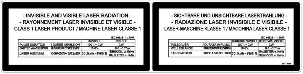
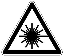
17 1. Overall management responsibilities 1-1. Complying with safety laws, regulations, and standards concerning laser machines in country or region of use The laser machine uses a Class 4 invisible laser for cutting materials and a visible semiconductor laser with a wavelength range of 650 nm for checking cutting positions. If the partitions and other protective covers are all closed and the safeguards are all enabled, the outside of the laser machine corresponds to that of a Class 1 laser product. If these conditions are not satisfied, the laser machine is a Class 4 laser product. Close the partitions and all other protective covers, and enable the safeguards. The visible laser is emitted even if the partitions are opened, but the visible laser belongs to a Class 3R laser product when its radiation is measured by AMADA. Use the laser machine in compliance with safety laws, regulations, and standards in the country or region of use Appointing laser safety officer Appoint a laser safety officer from among the employees who have enough knowledge and experience about the operation of the laser machine and the prevention of laser hazards. The laser safety officer must: Control keys and other devices for operating the laser machine. Inspect and maintain the laser machine, and save its inspection and maintenance records. Inspect and maintain the protective gear, and monitor its usage. Conduct the occupational health education of operators, and save their records. Practice other items necessary for preventing fires and other hazards due to the laser machine Posting name of laser safety officer and other information Post the following information on the laser machine or in an easy-to-see location near the laser machine: Name of the laser safety officer Laser hazardousness and harmfulness, and any other laser machine operating precautions 3


18 1-4. Having keys kept by laser safety officer Some controls are installed as keyswitches to prevent improper or unauthorized operation. Have the keys of the keyswitches kept by the laser safety officer. (For the positions of the keyswitches, refer to 6. Keyswitch and EMERGENCY STOP button arrangement drawing in this Part.) Keyswitches on NC control box LASER keyswitch MEMORY PROTECT keyswitch SHUTTER keyswitch MANUAL CUT keyswitch LINE CONTROL keyswitch (only for line operation specification) 1-5. Conducting safety and health education of operators When employing workers to be engaged in laser jobs, assigning workers to laser jobs, or assigning workers to different laser machines, conduct their safety and health education in compliance with safety laws, regulations, and standards in the country or region of use. Concerning the following items in particular, establish safety and health rules in compliance with this manual, and conduct the education and training of operators accordingly: Hazardousness and harmfulness of laser machines in compliance with the Hazard Information on Machine. Construction of laser machines Methods of operating laser machines Performance of protective gear and devices, and methods of handling them Emergency measures and evacuation 1-6. Eye health care Administer eye health care for workers regularly engaged in laser jobs in compliance with eye health care laws, regulations, and standards in the country or region of use if there are any such ones. As soon as any workers suspected of exposure to laser radiation are found, bring them to a doctor for examination or treatment. 4


19 1-7. Inspection and maintenance Perform maintenance on the laser machine before the start of the day s work. Before the start of the day s work, instruct the laser safety officer to check the laser beam path, interlock functions, safeguards, and protective gear. Try to find equipment failures or problems as early as possible. When you find a problem, repair it or take any other necessary measure to prevent an accident. Do not operate the laser machine with its maintenance doors and those of the NC unit left open. Do not repeatedly turn on and off the power of the laser machine at rapid intervals Precautions on clothing to wear during operation Do not wear loose clothing or jewelry when operating the laser machine. Otherwise you may be caught in or pulled into the laser machine. As dictated by the work to be performed, wear personal protective gear, such as a safety hat, laser safety goggles, dust safety goggles, safety shoes, ear plugs, gloves, a gas mask, or a dust mask. Select such protective gears that comply with specific work safety standards. 2. Prohibiting modification of laser machine 2-1. Prohibiting modification of laser machine and control circuit Never modify the laser machine and control circuit. Doing so may cause the laser machine to malfunction. 5
20 2-2. Prohibition of change to personal computer-based NC unit The laser machine is controlled by a personal computer-based NC unit. Any software or hardware changes may cause the laser machine to misoperate and lead to a serious accident. 1. Do not add or change any hardware (e.g., memory, SCSI card, PC card, CF card). 2. Do not remove or insert boards like the CPU board. 3. Do not install or uninstall software. 4. Do not change, add, delete, or move Windows files and folders. 5. Do not operate on the Windows system files (e.g., control panel and registry file). 6. Do not save files other than programs in the NC unit through a USB flash drive or through another computer connected to the AMNC system. 7. To prevent infection with computer viruses, do not use media that contain files and programs of unknown origin. 8. The AMNC-F comes standard with security software. This security software prevents the operation of computer viruses and other malicious software and the execution of software other than that operating in the AMNC-F Prohibition of removal of safeguards and of change of their installation position Do not remove the safeguards, entry prevention fences and covers, and do not change their installation position. Do not operate the laser machine with its interlocks removed. 3. Residual risk map peculiar to machine Model: LCG series For specific locations of residual risks on the machine, refer to 4. Residual risk list peculiar to machine described later. 6
21 3-1. Hazard map of machine For the peripheral equipment, refer to the Hazard Information on Machine in its manual. No. in residual risk list Upper row: Hazard Lower row: Hazard type Operation 4-2-(4) b,c,d,e Polyvinyl chloride Harmful gas, smoke, dust Nylon and polyurethane Harmful gas, smoke, dust Plastics Harmful gas, smoke, dust Materials whose safety is not ensured Harmful gas, smoke, dust Operation 4-2-(5) Operation 4-2-(7) High-frequency power supply Operation 4-3-(12) High-voltage parts Electric shock Maintenance 4-3-(11) Laser beam Fire burn, thermal burn Operation 4-2-(1) a,b Class 4 laser beam Laser Secondary radiation Laser Operation 4-2-(2) k Dust collector filter Fire burn, explosion Maintenance 4-3-(4)(5) Dust Harmful gas, smoke, dust Moving parts of machine Crushing Operation 4-2-(10) Workclamps Crushing Operation 4-2-(9) Materials Falling object Operation 4-2-(8) Parts just after cutting Fire burn, thermal burn Operation 4-2-(3), Operation 4-2-(4)f, Disposal 4-4-(1) Focusing lens Harmful gas, smoke, dust Maintenance 4-3-(7) Nozzle Abrasion, scraping Maintenance 4-3-(6) Scrap box Awkward posture, excessive exertion Operation 4-2-(2) b,d,i,j Laser beam Fire, explosion Combustible material Highly reflective materials Cutting defects Fire, explosion Operation 4-2-(2) a,e,f,g, Magnesium dust Fire, explosion Dust Fire, explosion Titanium, aluminum, and zinc dust Fire, explosion Titanium, aluminum, and zinc dust, and water Fire, explosion Maintenance 4-3-(9) Oil shot, shot agent Harmful liquid Installation 4-1-(1) Installation 4-1-(2) a,b Machine Impact Maintenance 4-3-(1)a,b Building Fire, explosion Moving parts of peripheral units Crushing Nitrogen gas Harmful gas, smoke, dust Oxygen gas Fire, explosion Maintenance 4-3-(8) Chiller, cooling fins, cooling fans Fire burn, thermal burn Installation 4-1-(3) Machine Live parts in faulty condition (indirect contact) Maintenance 4-3-(2) Primary power wiring Live parts (direct contact) Disposal 4-4-(3) CFC substitute Frostbite Harmful gas, smoke, dust Operation 4-2-(2) c,h Combustible materials Fire, explosion Dust, oxygen gas Fire, explosion Maintenance 4-3-(3) Dust Harmful gas, mist, smoke, dust Operation 4-2-(4) a, Dust, assist gas Harmful gas, smoke, dust Maintenance 4-3-(10) a,b,c Machine Impact Crushing Operation 4-2.-(6) Materials, moving parts of machine Entrapment Disposal 4-4-(2) Dust Harmful gas, mist, smoke, dust Operation 4-2-(11) Machine Fire, explosion Crushing 7
22 Installation 4-1-(4) Optional roof cover Operation 4-2-(1) a Shutter 8
23 4. Residual risk list peculiar to machine Model: LCG series 4-1. Installation (1) Precautions when lifting and moving machine WARNING Hazard Machine Description Use appropriate lifting devices and methods to lift and move the machine. Failure to do so may cause the machine to tumble or fall. Measure Ask Amada or a specialized contractor to lift and move the machine. Reference Installation Manual (2) Location of machine and protection around machine WARNING (a) Hazard Building Description If a combustible material ignites near or around the laser cutting machine, the fire may spread throughout the shop. Measure Install the machine in a fire-resistant building. (b) Hazard Moving parts of peripheral units Description You may collide with a pallet or other moving part around the peripheral unit or may get pinched in a pallet or other moving part. Measure Install a safety fence and a light curtain to prevent access to moving parts during operation. Reference Installation Manual (3) Precautions when installing electrical wiring WARNING Hazard Machine Description If you fail to install primary power wiring and ground wiring as specified, you may get an electric shock from ground-fault current or may get pinched in a malfunctioning machine. Measure Install primary power wiring and ground wiring as shown on the electrical reference drawing. 9
 that implies accessed with stairs and footbridge ; due to the fact that")
24 (4) Secondary reflected light by the roof WARNING Hazard Laser Beam Description During laser cutting, visible and ultraviolet light are emitted form the cutting point. This light can go to the top. Measure In case of a machine installed in a workshop where the offices are located in high position (over the working area) that implies accessed with stairs and footbridge ; due to the fact that some laser beam reflection can reach an employee, therefore it is required to equip the machine with an optional roof cover. Owing to possible laser beam reflection it is demanded : - Any kind of work to be performed in high position above the laser cutting area working must be prepared with protections such as appropriated curtains - Or the laser machine must be stopped during the time of the work. Office footbridge Aerial lift Risk due to laser radiation toward up specular radiation (second radius) 10
25 Risk area 11
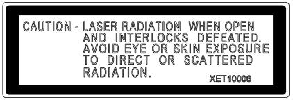
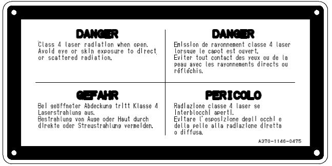
26 4-2. Operation (setup and cutting) (1) Checking for safety at start of operation WARNING (a) Hazard Class 4 laser Description If the enclosure of a Class 4 laser is broken, the laser beam may leak outside. The Class 4 laser beam is nm in wavelength and invisible. If the Class 4 laser beam directly enters your eyes or the reflected or scattered radiation from the worksheet surface hits you, you may lose your eyesight or may get burned. Measure At the start of the day s work, check the enclosure and other protective covers for breakage (holes) or burn marks and the door interlocks for operation. If any abnormality is found, stop the use of the machine and contact Amada. Wear the laser safety glasses (attached to the machine). Take care that the glasses cannot shield the laser beam when directly exposed to it. When you use the visible laser beam for checking the cutting position, wear the laser safety glasses and take care that the invisible laser beam does not directly enter your eyes. (b) Hazard Secondary reflected light (visible light and ultraviolet light) Description During laser cutting, visible light and ultraviolet light are emitted from the cutting point. If you directly look at highly bright visible light or at ultraviolet light, you may get your eyesight reduced. Measure Every day, check the enclosure and other protective covers for breakage (holes) and the safety devices for condition. If any abnormality is found, stop the use of the machine and contact Amada. Wear the laser safety glasses (attached to the machine). Take care that the glasses cannot shield the laser beam when directly exposed to it. When you use the visible laser beam for checking the cutting position, wear the laser safety glasses. Take care that the invisible laser beam does not directly enter your eyes. 12
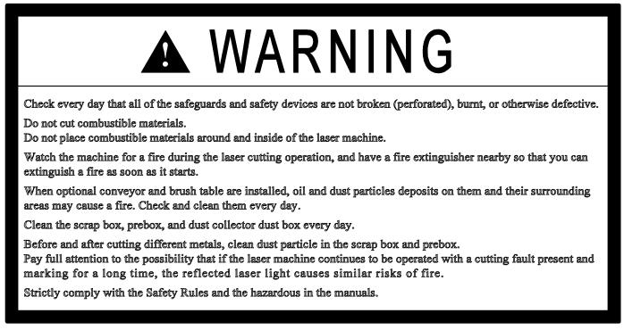
27 (2) Precautions against fire during laser cutting DANGER (a) Hazard Magnesium dust Description Dust generated from cutting magnesium and its alloys has the highest risk of explosion. Measure Reference WARNING (b) Hazard Laser beam Never cut magnesium and its alloys. Description A fire may occur at any time during laser cutting. Measure Do not allow laser cutting to be performed unattended. A source of fire may remain after laser cutting. Take care against fire after laser cutting. Install a fire extinguisher near the machine so that, should a fire occur, you can immediately put out the fire with the fire extinguisher. You must use different types of fire extinguishers for different types of fire. There are fire extinguishers for ordinary fires, oil fires, electrical fires, and special fires (metal fires, for example). Provide fire extinguishers suited for types of fires expected to occur in your shop. (c) Hazard Combustible materials Description If a combustible material is struck by the reflected light of the laser or spatter generated during laser cutting, it may ignite and cause a fire. Measure Never place combustible materials (typically, oil, grease, acetone, plastics, waste cloth, wood, paper, and dust collector filters) around the machine. Wipe off any oil adhering to the processing pallet. Reference Cleaning table and area around machine, Part 5, Maintenance. (d) Hazard Combustible materials Description Laser cutting of a combustible material may result in a fire. Measure Do not laser-cut acrylics, plywood, and other combustible materials. Doing so always carries a risk of fire. 13
28 (e) Hazard Dust Description Dust generate by laser cutting may present a fire risk as well as a dust explosion risk. A dust explosion occurs the instant three conditions, oxygen, dust concentration above the lower explosion limit, and minimum ignition energy, are all met. If a large amount of dust collects, it is scattered by a dust explosion and the scattered dust may result in a larger secondary explosion. Measure Clean the scrap box and the dust box of the dust collector every day. Reference Cleaning dust box of dust collector, Part 5, Maintenance Cleaning scrap box, Part 5, Maintenance (f) Hazard Titanium, aluminum, and zinc dusts Description When mixed with oxidized iron and copper dusts, dusts of titanium, aluminum, zinc, and their alloys collected in the machine, duct, and dust collector cause a thermite reaction, produce high heat, and explode. Measure Daily cleaning is important in preventing such dusts from collecting in the machine, duct, and dust collector. Dedicate the machine to cutting one type of material. Or before or after laser cutting such a material, completely remove the generated dust so that it does not mix with the dust from laser cutting of the next material. After laser cutting a material, change the dust box of the dust collector so that the collected dust does not mix with the dust produced by laser cutting of the next material. Reference Cleaning dust box of dust collector, Part 5, Maintenance Cleaning scrap box, Part 5, Maintenance 14
29 (g) Hazard Titanium, aluminum and zinc dusts, and water Description When the dusts of titanium, aluminum, zinc, and their alloys collected in the machine, duct, and dust collector react with water, they produce high heat and hydrogen gas and may cause an explosion. Measure Daily cleaning is important in preventing such dusts from collecting in the machine, duct, and dust collector. Dedicate the machine to cutting one type of material. Or before or after laser cutting such a material, completely remove the generated dust so that it does not mix with the dust from laser cutting of the next material. Never pour water on a metal fire. Be sure to have a fire extinguisher installed for metal fires. Reference Cleaning dust box of dust collector, Part 5, Maintenance (h) Hazard Dust and oxygen gas Cleaning scrap box, Part 5, Maintenance Description When dust and oxygen assist gas accumulate to high enough levels, they may cause a fire. Measure Constantly ventilate throughout the shop. (i) Hazard Highly reflective materials Description When a highly reflective material is cut, the reflected light may burn combustible materials in and around the machine. Especially, marking presents a higher fire risk. Measure Take care that the warning BEAM REFLECTING LEVEL 1 does not occur. Reference Warning stop EX2008 BEAM REFLECTING LEVEL 1, AMNC-F Alarms (j) Hazard Cutting defects Description If you continue to operate the machine with a cutting defect, the reflected light may burn combustible materials in and around the machine. Measure Take full care not to continue to operate the machine with a cutting defect. (k) Hazard Filter of dust collector Description If you continue to use a dirty filter in the dust collector, it may eventually ignite and cause a fire. Measure Check the filter and periodically change it. Leave a record of what you have done. Check and change the filter of the dust collector on a scheduled basis. Reference Cleaning dust box of dust collector, Part 5, Maintenance 3-2. Checking dust collection filter, Part 5, Maintenance 15
30 (3) Handling broken optical parts WARNING Hazard Focusing lens Description The focusing lens contains toxic zinc selenium. If absorbed into the body, zinc selenium may cause a fatal accident. If you inhale the dust of a broken les, you may run a great risk. Measure If you have dropped or broken the lens, sweep up the broken pieces and discard them in a waste container while taking care not to get cut by sharp fragments. Use stab-proof gloves, a mask approved by the U.S. Occupational Safety and Health Administration, or a respiratory mask. Wear safety glasses (with protection against dust infiltration from the sides), or goggles. If the dust is scattered, remove it with a damp mop or cloth. (4) Precautions against toxic gases and dusts WARNING (a) Hazard Dust and assist gas Description If dust and assist gas nitrogen or oxygen accumulate to high enough levels, they may do harm to you. Measure Reference Constantly ventilate throughout the shop. (b) Hazard Polyvinyl chloride Description When laser cut, polyvinyl chloride produces toxic hydrogen chloride gas. Hydrogen chloride gas readily dissolves in water to give hydrochloric acid. This hydrochloric acid badly corrodes equipment. Measure Never laser cut polyvinyl chloride. 16
31 (c) Hazard Nylon and polyurethane Description When laser cut, nylon and polyurethane produce toxic hydrogen cyanide gas. Measure (d) Hazard Plastics Never laser cut nylon and polyurethane. Description When laser cut, plastics may produce carbon monoxide and other toxic gases. Measure Do not laser cut plastics. (e) Hazard Materials whose safety is not verified Description When laser cut, these materials may produce toxic substances, depending on their type. Measure (f) Hazard Focusing lens Before you laser cut special materials or materials you have not laser cut before, ask their manufacturers if they may produce toxic gas or dust and if they present a fire or explosion risk when laser cut. Description If you inhale the vapor produced by a burning lens, you may be at risk. Measure If the lens has burnt, press the emergency stop button to turn off the laser beam. Escape from the place until the temperature drops low enough. When the vapor is not produced any more, open the windows to change all the air in the room. Take care not to inhale the vapor during this time. Discard the burnt lens in a sealable container while taking care not to touch it directly. (5) Precautions when working in moving range of machine WARNING Hazard Moving parts of machine Description You may get pinched in the moving parts of the machine. Measure Before you work in the moving range of the machine for loading worksheets or unloading parts or scrap, press the STOP button, and turn the SHUTTER keyswitch to OFF. 17

32 (6) Precautions when working with another or more workers WARNING Hazard Materials and moving parts of machine Description If the operator improperly operates the machine while two or more workers are loading materials or unloading parts together, the workers may get pinched in the materials or moving parts of the machine. Measure The machine must be operated by a single person familiar with how to operate the machine. When you load materials or unload parts with another or more workers, check each other s safety while checking their working conditions. (7) Precautions with electronic medical devices CAUTION Hazard High-frequency power supply (CO 2 laser oscillator) Description If you wear a pacemaker, defibrillator, or other electronic medical device, your electronic medical device may be adversely affected by the magnetic radiation generated by the machine. Measure (8) Precautions when unloading parts CAUTION Hazard As soon as you feel ill or strange, leave the workplace. Parts just after cutting Description If you touch to remove a part just after cutting, you may get burned by the residual heat of the part. Measure Wear leather gloves or take any other measure against burn injury. 18


33 (9) Precautions when loading worksheets CAUTION Hazard Worksheets Description The worksheet may drop from the table and injure your hands or feet. Measure Load the worksheet on the table so that it does not project from the table. (10) Precautions when clamping worksheets CAUTION Hazard Workclamps Description You may get your fingers pinched in the workclamps. Measure When you clamp the worksheet, do not reach to the workclamps. (11) Procedure when you feel danger at occurrence of trouble WARNING Hazard Machine Description If you continue to operate the machine after occurrence of trouble, the machine may malfunction and pinch you, or the machine may cause a fire and do unexpected harm to you. Measure As soon as you feel danger at the occurrence of trouble during the operation of the machine, press the red EMERGENCY STOP button. When pressed, the button is locked and can stop the machine totally. It can also turn off the power to the oscillator and stop the laser oscillation. As soon as you press the button, report the incident to the laser safety officer. Reference 6. Keyswitch and EMERGENCY STOP button arrangement drawing described later 3-3. NC control panel, Part 2, Controls 19
34 4-3. Maintenance (1) Precautions when checking and changing gas cylinder WARNING (a) Hazard Nitrogen gas Description If the nitrogen assist gas cylinder is piped improperly, it may leak the nitrogen gas. If the shop is filled with the nitrogen gas, you may be adversely affected by it. Measure After changing the nitrogen assist gas cylinder, adjust the nitrogen gas pressure after consulting your gas piping contractor or gas distributor. Reference Checking residual pressure of assist gas, Part 5, Maintenance (b) Hazard Oxygen gas Description If the oxygen assist gas cylinder is piped improperly, it may leak the oxygen gas. If the oxygen gas fills the shop, it may do harm to you. Measure After you change the oxygen assist gas cylinder, consult your gas piping contractor or gas distributor about how to adjust the oxygen gas pressure. Reference Checking residual pressure of assist gas, Part 5, Maintenance (2) Precautions when checking primary power wiring WARNING Hazard Primary power wiring Description If you inadvertently touch a live part when checking the shop s primary power wiring, you may get an electric shock. Measure Before you check the primary power wiring, turn off the power and turn off the shop circuit breaker switch. 20
35 (3) Precautions when cleaning workplace WARNING Hazard Dust Description Dust may do harm to you when inhaled and may present a fire risk when accumulated. Measure Clean the workplace every day. Sweep the floor of the workplace once or more per month. Vacuum or damp-dust the floor to prevent the dust from flying in the air, or wear a dust mask. Never use compressed air in the room to blow off dust from jigs and other objects. (4) Precautions when cleaning dust box of dust collector WARNING Hazard Dust Description When you clean the dust box of the dust collector, you may inhale the dust. When inhaled, the dust may do harm to you. Measure When you clean the dust box of the dust collector, wear a dust mask so that you do not inhale the dust. Wear long-sleeved clothing or rubber gloves to prevent your skin from direct contact with the dust. After the cleaning task, use a suction brush to remove the dust from your clothing so that the dust does not fly in the air. Or shake the dust off the clothing in outdoors. Reference Cleaning dust box of dust collector, Part 5, Maintenance (5) Precautions when checking and changing filter of dust collector WARNING Hazard Dust Description When you check or change the filter of the dust collector, you may inhale the dust. When inhaled, the dust may do harm to you. Measure When you check or change the filter of the dust collector, wear a dust mask so that you do not inhale the dust. Wear long-sleeved clothing or rubber gloves to prevent your skin from direct contact with the dust. After the cleaning task, use a suction brush to remove the dust from your clothing so that the dust does not fly in the air. Or shake the dust off the clothing in outdoors. Reference Changing dust collection filter, Part 5, Maintenance 21
36 (6) Precautions when cleaning scrap box WARNING Hazard Scrap box Description If you lift the scrap box by force when you clean the scrap box of scrap and dust, you may hurt your back. Measure Do not lift the scrap box by force. Remove the scrap from the scrap box and dispose of it. Reference Cleaning scrap box, Part 5, Maintenance (7) Precautions when checking and changing nozzle CAUTION Hazard Nozzle Description You may get your fingers hurt by a damaged nozzle. Measure Wear leather gloves or any other protective device to handle such a nozzle. (8) Precautions when checking and cleaning air heat exchanger of cooling unit CAUTION Hazard Cooling fins and fans of cooling unit Description If you touch the cooling fins or fan when you clean the air heat exchanger of the cooling unit, you may get burned. Measure Before you check or clean the cooling fins and fan, be sure to turn off the main power and wait 10 min or more. (9) Precautions when adding shot agent to shot tank CAUTION Hazard Oil shot and shot agent Description When you add the shot agent to the shot tank, you may get the shot agent in your eyes and may get your eyes reddened or stung by the shot agent. Measure If the shot agent gets in your eyes, carefully wash the eyes 15 min or more. If you wear contact lenses and can easily remove them, remove them and continue to wash the eyes. If the eye irritation persists, seek medical help at once. Reference Material Safety Data Sheet, Oil shot No. 9 B-15 SATO SPECIAL OIL CO., LTD. 22

 Hazard Machine When you maintain or adjust the machine with the air valve (residual pressure relief valve) set to EXH., lock out the air valve by padlocking it, for example.")
37 (10) Precautions when maintaining and adjusting machine WARNING (a) Hazard Machine Description Another worker may inadvertently turn on the power to machine to start the machine. Measure When you maintain or adjust the machine with the machine circuit breaker switch set to OFF, lock out the machine circuit breaker switch by padlocking it as shown above, for example. (b) Hazard Machine Description Another worker may inadvertently turn on the compressed air to the machine to start the machine. Measure (c) Hazard Machine When you maintain or adjust the machine with the air valve (residual pressure relief valve) set to EXH., lock out the air valve by padlocking it, for example. Description When you are maintaining or adjusting the machine, another worker may inadvertently operate the machine without noticing that you are doing so. Measure Before you maintain or adjust the machine, tag out the machine circuit breaker switch to inform other workers that you are working on the machine. Especially when working in the hazardous area of the machine, turn the machine circuit breaker switch to OFF and padlock it in the OFF state. (11) Precautions when cleaning mirrors in machine and adjusting alignment of mirrors WARNING Hazard Laser beam Description If you improperly work with the mirrors in the machine, you may get burned. Measure Be sure to ask Amada to do this work. 23

38 (12) Precautions against high voltage WARNING Hazard High-voltage parts (CO 2 gas laser oscillator) Description A high voltage of V is used in some parts of the oscillator. If you open the door of the oscillator and touch such a high-voltage part while the power is turned on to the oscillator or just after the power is turned off to the oscillator, you may get killed. Measure 4-4. Disposal (1) Handling optical parts for disposal WARNING Hazard Capacitors and some other parts in the oscillator may be still charged when the high-voltage power is already turned off to the oscillator. Never open the housing of the oscillator. If any trouble occurs in the oscillator, contact Amada. Focusing lens Description The lens contains toxic zinc selenide (ZnSe). If the used lens is disposed of improperly, it may cause a fatal accident. Inhalation of the dust from a broken lens may present a particularly serious health risk. Measure Until you dispose of the used or broken lens, strictly store and manage it out of reach of unauthorized people (particularly infants and children). Ask a licensed contractor or Amada to dispose of the lens according to a specified procedure. Never dispose of the lens like household waste. 24
39 (2) Precautions when disposing of recovered dust WARNING Hazard Dust Description When inhaled, the dust may do harm to you. Measure Seal the recovered dust in a can or bag so that it does not fly in the air. Dispose of it as industrial waste. Do not dispose of it like household waste. (3) Precautions when disposing of refrigerant in cooling unit WARNING Hazard CFC substitute Description If you get your skin in direct contact with the liquefied CFC substitute, you may get frostbite. If the CFC substitute gets in contact with a fire or hot metal, it may produce a toxic gas. If the CFC substitute is released into the atmosphere, it may cause ozone layer destruction and global warming. Measure 5. Warning labels When you want to have the CFC substitute drained or added when you dispose of or repair the cooling unit, ask a specialized contractor to do so as specified in the country or region of use. Keep the warning labels well noticeable and never remove them. If any warning label affixed on the machine is damaged or lost, immediately request AMADA for a new one and attach it to the same position. 25
40 26


41 5-1. Warning labels arrangement drawing 27

42 28


43 6. Keyswitch and EMERGENCY STOP button arrangement drawing SHUTTER KEYSWITCH EMERGENCY STOP BUTTON MANUAL CUT KEYSWITCH LINE CONTROL KEYSWITCH LASER KEYSWITCH MEMORY PROTECT KEYSWITCH 29
44 7. Warning label fanuc oscillator The oscillator uses high voltages and laser beam radiation. Such hazards are indicated with warning labels attached to the positions. In addition, there are some stickers for the explanation. This section describes the warning labels, stickers and their positions
45 1 Class identification label 2 Access label 3 Lifting method label 31


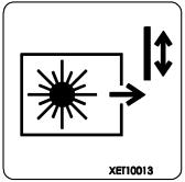
46 4 Access label 5 Certification label 6Label for regulating the atmospheric gasses in the oscillator housing 7 Aperture label 32

47 8 Ascent/Descent prohibited label 9 Discharge section label 10 Laser mark 33
48 34
49 Part 1 Description 1. Description General view Machine Frame (X-axis) Table Manual X-gauge block Workclamps Partitions Carriage Carriage (X-axis) Laser head (Y-, Z-, and B-axes) Bend mirrors NC unit Laser oscillator Cooling unit Dust collector (option) Shuttle table AS unit (option) Safety functions Operator safety Machine safety Specifications Configuration Environment Machine Laser oscillator Laser for processing Laser for positional confirmation NC unit Information on sound Declaration of Incorporation
50 1. Description 1-1. General view TABLE LASER OSCILLATOR SHUTTLE TABLE PARTITION 1-2. Machine Frame (X-axis) 1-2 NC CONTROL BOX The table, carriage (X-axis), and laser oscillator are installed on the frame. Racks are installed on both sides of the frame to move the carriage driven along the X-axis Table Skids are installed to the table to support a worksheet Manual X-gauge block The manual X-gauge block is a pin that serves as origin for clamping a worksheet. The worksheet is manually pushed against the manual X-gauge block to position it Workclamps The LCG shuttle table (LST) is equipped with four workclamps. Depending on the specifications of the machine, there is the manual clamp and the pneumatic clamp (option). The manual clamp involves using each clamp handle to open and close the workclamps (clamping and unclamping the worksheet). Operations for opening and closing the workclamps (clamping and unclamping the worksheet) on the machine can be performed by pressing the shuttle clamp open button or the foot switch. The maximum opening width of the workclamps is 40 mm {1.57 in.} for the pneumatic clamp Partitions The machine is provided with the partitions. You can open and close the sliding doors of the partitions by hand. Front partitions (three fixed panels and one door) Rear partitions (fixed panels) Side partition (folding door) Top partitions (sliding roofs)
51 1-3. Carriage Carriage (X-axis) The carriage is driven along the X-axis by the AC servo motors installed to the carriage. The carriage has the laser head (Y-, Z-, and B-axes) installed Laser head (Y-, Z-, and B-axes) The laser head consists of a laser head collision detector, a lens unit, and a nozzle unit. The laser beam emitted from the laser oscillator is focused by the lens of the laser head onto the worksheet on the table. The energy of the laser beam thus concentrated is used to cut the worksheet. The nozzle ejects the focused laser beam and the assist gas that increases the laser cutting efficiency and protects the lens during the cutting operation. The laser head is moved above the table by the carriage. It is vertically driven along the Z-axis. The B-axis vertically drives the lens unit to adjust the focal point. 1) Nozzle unit The nozzle unit consists of a nozzle and a nozzle holder. NOTICE Do not use lens with a focal length of 5 or less in the D-type nozzle. The interference of the laser beam in the nozzle may damage the nozzle. [1] Nozzle The nozzle emits the laser beam and assist gas. The nozzle is available in S 0.8E, S 1.0E, S 1.2E, S 1.5, S 2.0, S 3.0, D 1.4E, D 2.5, D 4.0, D 4.0C, D 7.0C. Use a nozzle that suits your job by referring to the processing condition file. 1-3
52 [2] Nozzle holder The nozzle is installed in the nozzle holder. The nozzle holder is slidable and simple to install and remove. The nozzle holder doubles as Z-axis tracking sensor. When the laser head strikes the worksheet or a workclamp, the nozzle holder may be damaged. If damaged, it can be changed. 2) Lens unit The lens is installed in the lens unit. The lens unit is also used to adjust the center of the laser beam at the cutting position of the worksheet. REFERENCE For the adjusting procedure, refer to 2-8. Centering nozzle in Part 3. [1] Lens The lens focuses the laser beam onto the worksheet on the table. The lens is available with a focal length of 5 or 7.5 (option). Use a lens that suits your job by referring to the processing condition file. [2] Lens holder The lens holder is fitted with a centering mechanism. The lens holder is available with a focal length of 5 or 7.5 (option). 3) Laser head collision detector This basic part is located where the laser head is installed along the Z-axis. It is equipped with a protection mechanism for preventing damage to the laser head and machine when the laser head (nozzle unit) is subjected to an external force Bend mirrors The laser beam released from the laser oscillator is changed in direction by six bend mirrors before it leaves the laser head. The angle of each bend mirror can be adjusted with screws, except for the bend mirror 1. From the one above the laser head, the bend mirrors are numbered or called 1, A/O, 2, 3, 4, and NC unit The NC unit controls the drive of the axes, motion of the respective components, and operation of the laser oscillator and cooling unit. These controls are divided into the NC unit and NC control box. The NC unit is installed in the lower left of the rear of the machine. The NC control box is in a fixed position so that the operation surface is facing to the left at the front of the left side of the machine. 1-4
53 1-5. Laser oscillator The laser oscillator is installed on the machine. The laser oscillator produces a CO 2 invisible laser beam by using a mixture of carbon dioxide, nitrogen, and helium as laser gas. The laser beam output conditions are determined according to worksheet material type and thickness, cutting rate and the like and are controlled by the NC unit. A red visible laser beam (semiconductor laser beam) can also be emitted. It is used to verify the cutting position of the worksheet before actually cutting the worksheet with the CO 2 invisible laser beam Cooling unit The cooling unit is installed separate from the machine. The cooling unit circulates cooling water through mirrors of the laser oscillator and machine, so that the laser oscillator can produce a stable CO 2 laser beam and the machine can be operated stable. Run the cooling water through a deionizer before its use. For the detailed operation and maintenance of the cooling unit, refer to its operator s manual Dust collector (option) The dust collector is installed separate from the machine. A dust collection opening is provided in the frame to remove the generated dust. The dust is collected in the filter of the dust collector. For the detailed operation and maintenance of the dust collector, refer to its operator s manual Shuttle table The shuttle table is installed on the left side of the machine. The table of the machine is of the pallet type. The shuttle table has two pallets and shuttles the pallets to the machine. The shuttle table is adjusted to the same pass line as the table of the machine, so that it can exchange a pallet with the table of the machine. For the detailed operation and maintenance of the shuttle table, refer to its operator s manual AS unit (option) The AS unit is installed alongside the machine. It stores two or more pallets in its shelves and automatically exchanges the pallets with the machine. 2. Safety functions The machine has functions that are designed to safeguard the operator as well as the machine itself as described below. 1-5
54 2-1. Operator safety Automatic power shutdown: The NC unit and the laser oscillator will be shut down automatically if an overcurrent is supplied. While supplying the high voltage to the laser oscillator, opening a door of the laser oscillator circuit breaker will stop the supply of the high voltage. Interlocks: The machine cannot start its automatic operation when the interlocks are actuated or the workclamps are open. The machine will stop as soon as it encounters either of the states mentioned above during its automatic operation. STOP and EMERGENCY STOP buttons: The machine cannot start its automatic operation when one of the STOP or EMERGENCY STOP buttons is left in the pressed state. The machine will stop its automatic operation as soon as one of the buttons is pressed Machine safety Laser head protection: The laser head will collapse at its joint if it hits the worksheet, etc., and the machine will stop. Servosystem protection: The machine will stop if a servo motor is overloaded or an irregularity has been caused in the servo system. Overtravel detection: The machine will stop if the laser head has overtraveled. Low air pressure detection: The machine will stop if the operating air pressure has gone down below the required pressure. Low laser gas pressure detection: The machine will stop if the laser gas pressure has gone down below the required pressure. Low assist gas pressure detection: The machine will stop if the assist gas pressure has gone down below the required pressure. Reduced cooling water flow detection: The machine will stop if the cooling water flow has been reduced below the required flow. Program precheck: The program can be checked for syntax errors and overtravels without running the machine prior to its execution for actual cutting. (This function is enabled or disabled by the PROGRAM CHECK button on the touch screen.) 1-6
55 Dead zone detection function: To prevent the laser head from striking a workclamp, the machine stops operating as soon as during automatic operation the laser head enters the dead zone where it is likely to strike a workclamp. This function is disabled when the DEAD ZONE CANCEL button is illuminated on the touch screen. The dead zone is as follows: X-axis = none, Y-axis = 40 mm {1.57 in.} Workclamp interference area deceleration function: To reduce the speed at which the laser head may strike a workclamp, the laser head is decelerated as it enters the deceleration area during automatic rapid feed or manual feed. This function is disabled when the CLAMP DECELERATION OFF button is illuminated on the touch screen. Low purge pressure detection: The machine will stop as soon as the purge pressure falls below the specified level. Dead zone detection function: When the DEAD ZONE CANCEL button on the touch screen is extinguished, the machine will stop its automatic operation as soon as the laser head enters the dead zone where the laser head may strike one of the workclamps. Aperture overheat detection: The machine will stop as soon as the aperture temperature rises above the specified level. Lens damage detection: The machine will stop as soon as smoke is detected from the burning lens. Dust collection filter damage detection (option): The machine and the dust collector will stop as soon as heat is detected from the burning dust collection filter. The dust collector has a device that supplies nitrogen gas and prevents the fire from spreading. Connect a nitrogen cylinder with the nitrogen inlet of the machine. 1-7
56 3. Specifications 3-1. Configuration The machine is composed of the units shown in the table below. Unit Model Qty Machine LCG Laser oscillator AF3500i-C (FANUC) Cooling unit 1 NC unit AMNC-F (FS31i-LB) 1 Dust collector 1 1 (option) Accessories 1 set 3-2. Environment Ambient temperature Maximum relative humidity Item Operating Storage/transportation Normal 5 to 35 C {41 to 95 F} 75%, non-condensing 20 to 60 C { 4 to 140 F} Short term (within 1 month) 95%, non-condensing Allowable vibration level Acceleration 0.49 m/s 2 {1.61 ft/s 2 } 9.8 m/s 2 {32.15 ft/s 2 } Amplitude 5 µm Allowable altitude 1000 m {3281 ft} m {39370 ft} Required illumination 500 lux 1-8
57 3-3. Machine Model Travel method Item Control method Axis travel Cutting area Cutting feed rate Max. rapid feed rate Max. worksheet mass Repeatable positioning accuracy Least input increment Drive feed method Assist gas type selector Table height Mass (only for machine) Power supply (only for machine) Short-circuit current rating (SCCR) X-axis Y-axis Z-axis X-axis Y-axis Z-axis X-axis Y-axis X-axis Y-axis Z-axis Specification LCG3015 X- and Y-axes: Optics travel Simultaneous control of X-, Y- and Z-axes, plus B-axis 3070 mm { in.} 1550 mm {61.02 in.} 100 mm {3.94 in.} 3070 mm { in.} 1550 mm {61.02 in.} 100 mm {3.94 in.} 0 to 120 m/min {0 to fpm} 0 to 120 m/min {0 to fpm} 120 m/min {393.7 fpm} 120 m/min {393.7 fpm} 80 m/min {262.5 fpm} 920 kg {2029 lb} ±0.005 mm {± in.} mm { in.} X-axis: Rack and pinion Y-axis: Rack and pinion Z-axis: Ball screw Automatic selection 840 mm {33.1 in.} 8200 kg {17750 lb} AC, three phases, 200 V -15% to +10%, 50/60 Hz 220 V -15% to +10%, 60 Hz 63 kva Icu : 50 ka 1-9
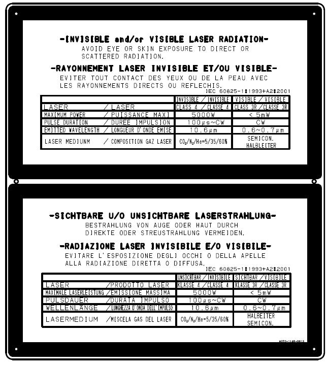
58 3-4. Laser oscillator Laser for processing Model* Item Specification AF3500i-C Class 4 For cutting Oscillation method Laser output Output beam Rated output Stability Pulse Polarization Laser gas Peak output Frequency range Duty range Beam wavelength Beam mode Beam diameter Beam dispersion angle Mixture ratio Gas flow rate Min. cooling water flow rate (Circular type) Dimensions (W D H) Circular polarizer Invisible Fast axial flow 3500 W ±2.0% (during rated-output closed-loop control) 3500 W 5 to Hz 0 to 100% 10.6 μm Low-order mode 22 mm {0.866 in.} at oscillator output Below 2 mrad Circular polarization CO 2 : He : N 2 = 5 : 61 : 34 (Volume ratio, He balance) Allowable of compositional ratio: ±2% Approx. 10 L/h {0.35 ft 3 /h} 160 L/min {42.3 US gal/min} mm { in.} Yes (built in laser oscillator) *AF3500i-C is registered trademarks of Amada Co., Ltd. His official model name at FANUC Corporation is C3500i-C. Throughout this manual, please read C3500i-C for AF3500i-C. 1-10
59 Laser for positional confirmation Model* For aiming Class Rated output Item Pulse duration Emitted wavelength Laser medium Specification AF3500i-C Visible 3R <5 mw CW 0.6 to 0.7 m Semiconductor *AF3500i-C is registered trademarks of Amada Co., Ltd. His official model name at FANUC Corporation is C3500i-C. Throughout this manual, please read C3500i-C for AF3500i-C. 1-11
60 3-5. NC unit Model Item NC control method Control functions Program input methods Least input increment Minimum position detection accuracy Program storage capacity Environment NC modes Display functions I/O interfaces Display Ambient temperature Max. relative humidity Specification AMNC-F (FS31i-LB) Semi-closed loop method X-, Y- and Z-axes simultaneous control Laser oscillator control Keyboard USB LAN (Ethernet) mm { in.} mm { in.} 128 MB Executable program size depends on NC memory capacity NC memory capacity: 256 m of tape (about 1 MB) 5 to 40 C {41 to 104 F} 75% without dew condensation RETRACT, MEMORY, MANUAL Pre-edit Schedule Program Result LAN, USB Utility Processing conditions Maintenance 15-inch color LCD touch screen 1-12
61 3-6. Information on sound INFORMATION ON SOUND IN ACCORDANCE WITH ACT Section Appendix 1 Transposing into French law the 89/392 Machine Directive and mentioned in article R from the Labor Code. AUDIBLE EMISSION AT WORK STATION: LA eq = 72.8 dba, when machine is operating SUS304 Stainless Plate Thickness: 10 mm {0.39 in.} Size: 1000 x 1000 mm {39.37 x in.} Cutting feed rate: 0.8 m/min {31.5 in./min} Laser output: 3500 W Assist gas pressure: 1.5 MPa {217.5 psi} 1m (3.28ft) ADVICE FOR DECREASING THE DAILY SOUND EXPOSURE LEVEL The sound level emitted by a machine depends greatly upon the setting up conditions and the environment of that machine, on the thickness and nature of the materials being worked and of the tooling being used. Depending on the site layout, it may be necessary to use technical means to reduce noise or to organize work so as to protect neighboring workstations: workstation distances, screens, partition doors, acoustic correction of premises' walls, decreased exposure time of operators to noise. Wearing individual aural protection is highly recommended in all cases. 1-13

62 3-7. Declaration of incorporation Each machine comes with an EC declaratrion of incorporation like the example bellow: 1-14
63 Each machine is fitted with a numerical plate fixed permanently on the frame, and a CE, plate in accordance with the current regulation. 1-15
64 1-16
65 Part 2 Installation 1. Location and foundation Secondary reflected light by the roof Floor plan drawing LCG LST Foundation drawing LCG LST Lifting Transportation Leveling Removing clamps Air supply Standard specifications of LCG series Laser gas supply Assist gas supply Piping work drawing for air Piping work drawing for gas Cooling water supply Piping work drawing for water Electric power supply Electric parts arrangement drawing Hydraulic oil supply Cleaning
66 1. LOCATION AND FOUNDATION Determine the installation location and the required space for the machine and its auxiliary equipment and provide the required foundation according to the plan supplied by AMADA. Be sure to reserve ample space around the machine and its auxiliary equipment to allow for worksheet handling and maintenance operations. The location requires the following conditions: The foundation must be firm, level concrete floor that resists seismic acceleration of up to 0.49 m/s 2 {0.05G} and amplitude of up to 5 m. The location must be isolated from any nearby equipment that produces dust or vibration; although its immunity level complies with the Electro-magnetic Compatibility Directive (Dir.89/336), the machine should be at least 3 m {10 ft} away from... The ceiling must be at least 3 m {10 ft} high above the floor. The location must be outside of any flammable or contaminable environment and be provided with ventilation facilities. The machine and its auxiliary equipment must not be directly exposed to sunlight, or hot or cold air. The ambient temperature must be between 5 to 35 C {41 to 95 F} with a relative humidity of below 75% and without dew condensation. Floor anchoring should be considered when preparing arrangements. In this respect, the engineering plans are references. CAUTION Any electrical cable should be protected either through a duct, or a sufficiently thick gullet, or by providing an aerial installation, so as to risk of falling into the working area. LCG3015 (LST specification) MASS 8050 kg {17750 lb} 1-1. Secondary reflected light by the roof Description During laser cutting, visible and ultraviolet light are emitted form the cutting point. This light can go to the top. M e a s u r e In case of a machine installed in a workshop where the offices are located in high position (over the working area) that implies accessed with stairs and footbridge ; due to the fact that some laser beam reflection can reach an employee, therefore it is required to equip the machine with a roof cover. Owing to possible laser beam reflection it is demanded : - Any kind of work to be performed in high position above the laser cutting area working must be prepared with protections such as appropriated curtains - Or the laser machine must be stopped during the time of the work. 2-2

67 Office footbridge Aerial lift Risk due to laser radiation toward up specular radiation (second radius) 2-3
68 2-4 Risk area
69 1-2. Floor plan drawing To secure safety, below conditions should be followed. 1 Never place flammable materials around the machine. Sparks may fly and ignite any flammable materials nearby. 2 The floor of working area of the machine is recommended to be painted to show it as a "Hazardous area" and make it inside of that area. 3 Do not install the machine where there are any obstacles such as columns or a wall in the maintenance area to prevent any persons being caught between the table and obstacles. 2-5
70 2-6
71 LCG LST 2-7
72 2-8
73 1-3. Foundation drawing Refer to the page 1 for the machine mass. Allowable ground bearing capacity for installing the machine is 55 kpa {7.98 psi} Refer to this drawing also when carrying out auxiliary work (such as operator floor construction, waterproofing, and vibration isolation). Do not install the machine where it may be exposed to large vibration from the outside of the factory. The maximum allowable vibration acceleration and amplitude for the machine are 0.49 m/s 2 {0.05 G} and 0.5 m, respectively. Exercise particular care when the machine must be installed near other machine that produces vibration, such as the numerically controlled turret punch press (NCT) or shearing machine, or in the factory alongside the road used by heavy trucks. If the machine must be installed in such environment, use vibration isolators (such as AMADA MAV) for the vibration-producing machine, and cut a trench, at least 25 mm wide and as deep as shown on the drawing in the foundation around the machine. Install the machine where there are no columns and obstacles in the maintenance space. Install the machine where it is not exposed to direct sunlight and air from air-conditioning equipment. Ceiling height of 3 m {10 ft} or more from the floor is required as maintenance space. Base plates, washers, anchor bolts, jack bolts, nuts, and bolts necessary for installing the machine are supplied with the machine. Foundation drawings are subject to change without prior notice. 2-9
74 2-10
75 LCG LST 2-11
76 2-12

 (EX) MODEL Mass L1 L2 L3 L4 L5 LCG3015 (LST) 8200 kg {18080 lb} 980 mm {38.6 in.")
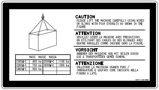
77 2. LIFTING WARNING Have qualified contractors perform all lifting work. Use a crane and wire ropes that have ample capacity to lift each piece of equipment. Keep the opening angle of the spread wire ropes at less than 60 degrees. Machine Lift the machine by using the lifting tackle as shown in the figure below. Balance the machine carefully when lifting it and lower it slowly to protect it against impacts. The mass of the machine and distance "L1" to "L5" between the lifting hooks are as follows: LST specification (EU) (EX) MODEL Mass L1 L2 L3 L4 L5 LCG3015 (LST) 8200 kg {18080 lb} 980 mm {38.6 in.} 980 mm {38.6 in.} 1479 mm {58.2 in.} 1571 mm {61.9 in.} 3470 mm {136.6 in.} Dust collector, cooling unit, and transformer For lifting the above equipment, refer to the separate manuals. 2-13
78 3. TRANSPORTATION Introduction : You will find here below the minimum recommendations regarding the fixation (on vehicle) and the transport which do not disclaim the Amada sales companies responsibility in a matter of fixation the case on vehicle (fixing, locking, etc for securing the transport) and the transport. They are entirely responsible for these operations and they have to increase the means of fixing, securing and protecting for the transport, if they estimate it necessary. The placement of the case on vehicle is carried out, with the means of handling of the factory, by Amada Europe staff according to the instructions of the transporter for a balanced distribution so as to ensure the stability of the vehicle and the safety of transport. The truck must be suited to the loading and in good condition (see tables on next pages), The driver must have a waterproof tarpaulin which must be in good condition and right size (see tables on next pages), without holes and dry. We remind you that the polyethylene tarpaulins which protect the machines are dustcover only and are not waterproof. The driver must have at minimum 6 suitable straps, in good condition, per box or case. The driver must have a transport letter/cmr, and a transport order note of the sender or similar document specifying the destination, the type and the serial number of the machine. The driver must have also a copy of the safety protocol of the factory related to the loading and unloading operations of the road haulage protocol completed and signed by Amada Europe and the road haulage company (according to the French low : Decree dated 26 th April 1996). 2-14
79 Here below a tables indicating the trailer type and tarpaulin sizes according to the different machines types. These machines are built with high technologies and must be handled with care. For information, the semi-trailer size (inner size) is L = 13.7 / l = 2.48 / h = 3m LCG Crate dimension : BOX / CAISSE Machine Type / Acessories AESA Code Length (mm) Width (mm) Height (mm) Weight (Ton) Length Tarpaulin Width Trailer type LCG 3015 L m 11m Transformer 63kVA (For 3,5kW oscillator) L ,350 Flat bed trailer / Tank transporters Included in the machine crate Crate handling : 2-15
")
80 Chains dimensions : Layout of LCG loading process : View of the LCG machine loaded on the tank transporter (flatbed trailer) 2-16


81 General view of the loaded machine : Straps to secure the crate on the trailer. View of the LCG machine loaded on the tank transporter (flatbed trailer) Note : For the general information for transportation cares for the rest of the current CHV product, please refer to the FT-V1-I-016-FE 2-17

82 4. LEVELING Place spirit levels on the top shaved surface in the X- and Y-axis directions. Tighten the jack bolt to level the laser machine. The laser machine must be level to within 0.8 mm/m in both the X- and Y-axis directions. When the leveling of the laser machine is finished, securely tighten the locknut to fix the jack bolt. When the concrete is completely dried, securely tighten the locknut to fix the machine. DETAILS OF ANCHOR BOLT SECTION 5. REMOVING CLAMPS The various kinds of clamps should be used only during the transportation. Especially the clamps used for resonator of laser oscillator should be loosened during the storage. Storing the resonator as fixed with clamps for a long time will cause its distortion. The clamps of laser machine is provided for X axis and NC control box. The clamps of laser oscillator are provided for cavity, shutter but not for turbo blower. 6. AIR SUPPLY Perform air piping work as shown on the PIPING WORK DRAWING FOR AIR. Using stainless steel pipe or pressure hose, connect an air compressor with functions recommended by AMADA and an air dryer compatible with the capacity of the air compressor to the machine. If the air compressor has its own air dryer, there is no need to install a standalone air dryer STANDARD SPECIFICATIONS OF LCG SERIES Standard specifications: when one of purge air unit, Clean Cut function, and Air Cut +Eco Cut function is to be used Air compressor 15 kw {20 HP} or equivalent Fitted with air dryer or connected with standalone air dryer Start of air dryer 2 to 3 minutes before start of air compressor Operation of air compressor with air intake closed Guaranteed air flow: 1550 NL/min Supply air pressure: 0.93 MPa {134.9 psi} or more Air flow required by machine: 1550 NL/min 2-18

83 NOTE Install the air compressor and air dryer as close as possible to the machine. Be sure to install the air dryer. Be sure to use hose bands at hose connections to prevent hose removal. Be sure that the air compressor outlet temperature remains in the range of 5 to 35 C {41 to 95 F}. If this temperature is higher or lower than specified, the performance of the purge air unit may deteriorate to reduce the quality of parts produced. Entry of oil, moisture, chips, and other impurities into the air piping of the machine may cause machine damage or malfunction. Before connecting to the air piping of the machine, be sure to flush or clean it with nitrogen or filtered air. Hose drain from the filter in the air line and from the filter in the machine to a ditch. The air piping work drawing is subject to change without notice. WARNING The maximum possible compressed air pressure is 0.97 MPa {140.7 psi}. 7. LASER GAS SUPPLY WARNING Secure the laser gas cylinder carefully so that it will not move or fall down accidentally. Connect the primary connector of the regulator directly to the laser gas cylinder. Then connect the regulator's secondary connector with the GAS IN connector on the laser oscillator by using the accessory hose and remove the cap from the GAS OUT connector. GAS REQUIREMENT Mixture ratio: 5% CO 2, 34% N 2, 61% He ( Volume allowances of each gas : 2% ) Purity: Over 99.99% Water content: Below 5 ppm Hydrocarbon content: Below 1 ppm REGULATOR (with stop valve) REQUIREMENT Maximum flow rate: 2 L/min {123 in 3 /min} Gas consumption: 0.17 L/min {10.3 in 3 /min} Gas pressure: 0.15 to 0.2 MPa {21.8 to 29.0 psi} Primary gauge: Readable up to 25 MPa {3600 psi} Secondary gauge: Readable up to 0.6 MPa {87.0 psi} Primary connector: Compatible with cylinder connector Secondary connector: 6 mm O.D. 2-19
84 8. ASSIST GAS SUPPLY WARNING The pressure used should be less than 0.97 MPa {140.7 psi}. Have the assist gas cylinder supplier connect the cylinder and the evaporator. Secure the assist gas cylinder carefully so that it will not move or fall down accidentally. Perform gas piping as shown on the PIPING WORK DRAWING FOR GAS. Connect the assist gas cylinder with an evaporator that has a capacity of 40 m 3 /h {1420 ft 3 /h} and is equipped with a pressure gauge. Then connect the evaporator with an assist gas intake (see below) on the back of the machine. (Refer to "Air Supply" above when using air as assist gas.) ASSIST GASES AND INTAKES USED Liquefied O 2 : Liquefied N 2 : Air: CONNECTING PIPES AND HOSES Cylinder Evaporator: OXYGEN intake CLEAN CUT intake AIR intake Copper pipe with thickness of over 1 mm {0.039 in.} or hose with pressure resistivity of over 1.5 MPa {215 psi}, both of compatible size. Evaporator Machine: Copper pipe with thickness of over 1 mm {0.039 in.} and 15 mm I.D. or hose with 1/2" I.D. and pressure resistivity of over 1.5 MPa {215 psi} Piping work drawing for air Piping STD (Air Cut Function) Option (HP-easy-cuttin g) PIPING PARTS LIST (to be prepared by customer) Part No. 1 Compressed air or compressor Part Size Qty Refer to page 17 2 Air dryer Capable of treating compressed air described above Hose ID: 1/2" Normal operating pressure: 1 MPa {145 psi} 3 Coupler 30SH (Nitto) 1 4 Hose band AS requir ed at site 2-20
85 2-21
86 2-22
87 8-2. Piping work drawing for gas Piping Laser oscillator gas See NOTE 4 PIPING PARTS LIST (to be prepared by customer) Part No. 1 Mixed gas for laser oscillator See NOTE 2 Part Size Qty Gas composition: CO 2 : N 2 : He = 5 : 34 : 61 vol. % Volume allowances of each gas : 2% Gas purity: Over 99.99% 2 Gas Regulator JET-S106 (Nissan Tanaka) or equivalent Primary pressure: 25 MPa {3626 psi} Secondary pressure: 0.6 MPa {87.0 psi} (with needle valve) Setting pressure: 0.15 to 0.2 MPa {21.8 to 29.0 psi} Piping tube (Standard part) Connector (Standard parts) 66-P-Y 3/8" (Imperial) m B RT (SWAGELOK) 1 SS-6M0-6-6 (SWAGELOK) 1 Nylon ferrule NY-600-SET (SWAGELOK) Dia. 6 mm straight hose coupler (Tanabekogyo) Cutting gas 3 Liquid oxygen 132 m 3 (FIF) Gas purity: Over 99.99% 4 Evaporator See NOTE 1 Capacity: 40 m 3 /h or more (Evaporator is not required if compressed oxygen is used) 5 Gas Regulator Minimum flow rate: 40 m 3 /h Max. operating pressure: 0.99 MPa {143.6 psi} (secondary side) 6 Copper pipe ID: 15mm Wall thickness: 1mm (0.04 in) 7 High-pressure hose ID: 1/2" Normal operating pressure: 1.5 MPa {217.6 psi} AS required at site 8 Hose band
88 Piping Non-oxidation cutting gas See NOTE 5 HP-easy-cutting assist gas piping PIPING PARTS LIST (to be prepared by customer) Part No. Part Size Qty 9 Liquid nitrogen 107 m 3 (FIF) Gas purity: Over 99.99% 10 Evaporator See NOTE 1 Capacity: 40 m 3 /h or more (Evaporator is not required it compressed) 11 Regulator Minimum flow rate: 40 m 3 /h Max. operating pressure: 0.99 MPa {143.6 psi} (secondary side) 12 Copper pipe ID: 15mm Wall thickness: 1mm (0.04 in) 13 High-pressure gas hose ID: 1/2" Normal operating pressure: 1.5 MPa {217.6 psi} 14 Hose band 2 15 Coupler 400PM (Nitto) 1 16 Coupler 400SH (Nitto) 1 17 Coupler 30SH (Nitto) 1 18 Hose Band 2 Dust collector 19 Nitrogen gas 7m 3 Cylinder 1 20 Gas regulator SGⅡ(Koike Sanso) or equivalent Setting pressure (secondary pressure): 0.5 MPa {72.5 psi} 21 Gas hose ID: 1/4" Operating pressure: 1.0 MPa {145.0 psi} NOTE AS required at site 1) No evaporators are required if compressed oxygen and nitrogen are used in place of liquid oxygen or nitrogen, respectively. 2) It is recommended to have a spare cylinder each of laser oscillator gas and assist gas. 3) Be sure to install an air dryer No.2. 4) Piping hose for oscillator gas is supplied tube of 7 m as a standard accessory. Consult AMADA if longer hose is required. * Never use a copper piping. * Do not use any hose other than the dedicated hose. 5) Non Oxidation cutting needs pressure 0.85 MPa {123 psi} and gas flow 600 L/min at a cutting head. Please consider a loss in the piping (about 0.1 or 0.2 MPa {14.5 or 29.0 psi}). 6) Be sure to use hose bands to all rubber tube so as to avoid it to be deteriorated by shock, cut or crushed. 7) Please secure gas cylinders not to be fallen down. 8) This piping instructions are subject to change without prior notice
89 2-25
90 2-26
91 9. COOLING WATER SUPPLY Determine the installation location and the required space for the chiller (cooling unit) and provide the required cooling water supply according to the PIPING WORK DRAWING FOR WATER or another plan supplied by AMADA Piping work drawing for water Piping A: Laser oscillator water supply piping Laser oscillator water return piping B: Chiller water supply piping Chiller drain piping PIPING PARTS LIST (to be prepared by customer) Source AF3500i-C Part No. Part Size Qty 1 Nipple 1-1/4"(SUS) 1 2 Hose nipple 1-1/4" 4 (minimumqua ntity) 3 Hose band 1-1/4" 4 (minimumqua ntity) 4 Water hose 1-1/4" Normal operating pressure: 0.5 MPa {72.5 psi} 5 Socket 1-1/4" 4 6 Piping 1-1/4" (treated against corrosion and freezing) As required at site As required at site 7 Elbow 1-1/4" As required at site 8 Water flow meter FC-AP70-1-B (TFLO Corporation) or equivalent 9 Hose nipple 1/2" 2 10 Hose Band 1/2" 2 11 Hose 1/2" As required at site 12 Hose nipple 3/4" 1 13 Hose band 3/4" 1 14 Hose 3/4" As required at site 1 NOTE 1) Use stainless pipe or vinyl-lined pipe or high-pressure hose for piping. And use fittings made of stainless steel or brass for protection against corrosion. 2) Use rubber hose and union as shown in the drawing. It is necessary for maintaining the machine. 3) Provide the bypass shown in the drawing. The bypass is used for cleaning and designed to prevent the wasteful use of the water purifier. 4) Where the cooling unit is likely to freeze, be sure to use antifreeze during the freezing period as described in the manual of the cooling unit. 5) The water purifier may burst when the supply water pressure exceeds 0.35 MPa {50.8 psi}. Be sure to use a water supply regulator. 6) Piping details in cooling unit side may be changed depending on types of cooling unit. 7) This piping instructions are subject to change without prior notice. 2-27
92 2-28
93 2-29
94 2-30


95 10. ELECTRIC POWER SUPPLY WARNING Have a qualified electrician carry out all electrical work in order to prevent injuries or accidents. NOTICE The machine requires a 3-phase, 200 VAC±10%, and 63 kva power supply. Use a shop circuit breaker of at least 160 A. For the recommended primary power cable specifications and connection method, see the table below. Conductor material Rated conductor temperature Copper (use copper conductors only) 75 C Conductor diameter 35 mm 2 Cable: max length 20m Terminal arrangement L1, L2, and L3 Supply the machine from a power source different from that for welding, drilling, sanding, or grinding machines to protect it from electrical noise and voltage drop. Install the crimp terminals so that their poles become parallel as shown below. 1 The machine transformer requires a 3-phase, 400 VAC±10%,50/60 Hz, and 63 kva power supply. 2 The customer must protect a differential circuit breaker, 100mA, 125 A curve D to protect the main line 2-31
96 Earth All class 1 equipment must have an earth connection. This necessity also applies to operation and floor drainage for any interference. The section of the earth conductor must, of course, be sufficient. For added safety, earth distribution should use a STAR configuration from the supply panel terminal block. In the same way as the electrical installation, the standard of the "earth" must be checked regularly by an approved organization. Interference linked with network and environment NOTICE Whatever process is used, never solder or weld any components onto the machine as this could cause damage to mechanical, electrical and electronic devices. Some electronic components may, consequently, be exposed to abnormal or excessive voltages and currents liable to cause their destruction. It may be necessary to consider the interposing of certain additional elements without a galvanic link to the networks (voltage stabilizer, inverter, converter group, transformer, insulation transformer, etc.) If the need arises, the standard of the electrical power supply must be examined by an approved organization and the results of the examination after analysis will determine the type of equipment needed. The following interference may be considered as disturbing to all electronic systems. Electrostatic discharge Electrostatic discharge is particularly critical where the ambient relative humidity levels are low: it is for instance not unusual for a person or a group of people on the move to generate discharges amounting to several thousands of volts when touching a door handle or a cabinet frame. It may be necessary to install an anti-static environment. The machine has complied with the tests required by the European standard EN related to the immunity to electrostatic discharges. Transients on the network supply Transients are spurious pulses propagating along network conductors and which may affect system operation. They may have internal origins: welding unit for instance, or may be generated by any other machine generating noise in the sector; they can also be external: stormy weather, nearby factory, etc. The machine has complied with the tests required by the European standard EN related to the immunity to fast transients. 2-32
97 Stormy weather The accumulated charges during storms may cause transients to arise on electrical lines or interconnecting cables. Do not use long overhead lines. Magnetic fields A variable magnetic field will cause phenomena of induction in circuit loops and generate a considerable amount of unwanted voltage. Cathode ray tubes which are sensitive to magnetic fields and indicate the sensitivity by a change in the chromatics of the image or its geometry, are provided with a protective shield. Electro-magnetic medium or high frequency radiations This type of interference may cause many problems in different systems (operational amplifiers, computer memory, etc.). In general, the scope of the interference observed depends upon the duration and intensity of such radiation. Although the machine has complied with the tests required by the European standards EN and 50141, it is recommended to install the punching machine in an environment free of the above mentioned interferences. 2-33
98 2-34
99 10-1. Electric parts arrangement drawing 2-35
100 2-36
101 11. HYDRAULIC OIL SUPPLY The gas blower and the vacuum pump in the laser oscillator require hydraulic oil. Refer to Operator's Manual for specified hydraulic oils and filling procedure. 12. CLEANING Remove the rust preventive grease from the machine surface by using a cleaning oil and then apply lubricant to the surface. NOTICE Do not use solvent to remove grease. If used, it will damage the coating of the machine surface. 2-37
102 2-38
103 Part 3 Controls 1. Arrangement and names of controls Circuit breaker switches NC control box Touch screen ON/OFF panel NC control panel USB ports Handwheel control box interface Handwheel control box Rear control cabinet
104 1. Arrangement and names of controls LCG3015 LASER OSCILLATOR CIRCUIT BREAKER SWITCH MACHINE CIRCUIT BREAKER SWITCH NC CONTROL BOX 3-2

105 2. Circuit breaker switches Machine circuit breaker switch NOTICE Machine circuit breaker switch Used to turn on and off the power of the machine and the NC unit. The flow of overcurrent automatically turns off the power of the machine and the NC unit. The lever can be padlocked when the switch is turned to OFF. Laser oscillator circuit breaker switch NOTICE Do not turn the laser oscillator circuit breaker switch to OFF when the LASER READY light on the NC control box is illuminated. Turn the laser oscillator circuit breaker switch to ON to make the laser oscillator ready for turning on its power. To turn off the power of the laser oscillator, press the POWER OFF button. After power-off processing, the laser oscillator is powered off. The laser oscillator circuit breaker switch automatically changes to TRIP. When manually turning off the power of the laser oscillator, press the POWER OFF button. When the message It is now safe to turn off your computer appears on the touch screen, turn the laser oscillator circuit breaker switch to OFF. When a failure like a short occurs or an overcurrent flows during the operation of the machine, the laser oscillator circuit breaker switch automatically changes to TRIP to turn off the power of the laser oscillator. In the breaker tripped state, stop the use of the machine, and contact AMADA. 3-3
106 3. NC control box The NC control box consists of a touch screen, an NC control panel, an ON/OFF panel and a USB ports among other things. ON/OFF PANEL LCD DISPLAY USB PORT NC CONTROL PANEL KEYBOARD 3-1. Touch screen This is a 15-inch color LCD touch screen. Press one of the buttons displayed on the screen to select the corresponding function. These functions allow you to set the machine operating controls and to display and edit the programs. You can also check the status of the machine. REFERENCE For the details of the applications, refer to Part I, Displays, in the reference manual of the AMNC-F. 3-4
![3-2. ON/OFF panel [1] POWER buttons POWER ON button Pressed to illuminate the button light and turn on the power of the NC unit.](/docs-images/87/96769653/images/107-0.jpg "The NC READY light on the NC control panel illuminates to indicate that the NC unit is ready.")
107 3-2. ON/OFF panel [1] POWER buttons POWER ON button Pressed to illuminate the button light and turn on the power of the NC unit. The NC READY light on the NC control panel illuminates to indicate that the NC unit is ready. To turn on the power of the NC unit, turn the machine circuit breaker switch to ON and press the POWER ON button. Illuminated: The power of the NC unit is turned on. Extinguished: The power of the NC unit is turned off. POWER OFF button NOTICE Do not turn off the power of the NC unit while a program is being executed or the access LED of the USB flash drive is flashing. Press the POWER OFF button to illuminate itself. At the same time, a buzzer continues to sound for 10 seconds. The button then flashes, and the NC unit, machine and laser oscillator power off. The machine circuit breaker switch and laser oscillator circuit breaker switch automatically change to TRIP. Within the 10-second time during which the buzzer sounds as soon as the POWER OFF button is pressed, the power-off processing procedure can be cleared by pressing the button again. Flashing: The power-off processing procedure is being executed. Extinguished: The power-off processing procedure is not being executed. [1] [2] [3] [4] [2] LASER keyswitch and lights LASER keyswitch Starts and stops the laser oscillator. ON: Starts supplying the laser gas to the laser oscillator and then the high voltage to the laser oscillator. OFF: Stops supplying the high voltage to the laser oscillator, removes the laser gas, and stops the laser oscillator 5 seconds later. When the machine is not in use, turn the keyswitch to OFF, remove the key from the keyswitch, and hand the key to the laser equipment manager for his safekeeping. 3-5
108 3-6 NOTE When the machine enters an emergency stop state while the laser oscillator is starting up, the HIGH VOLTAGE light extinguishes, and the supply of the high voltage to the laser oscillator stops. Clear the emergency stop state, reset the alarm, and turn the LASER keyswitch to OFF and turn it back to ON within 5 seconds. The HIGH VOLTAGE light flashes. When the preparation is completed for supplying the high voltage to the laser oscillator, the HIGH VOLTAGE light illuminates, and the laser oscillator restarts. LASER READY light Extinguished: The LASER keyswitch is set to OFF. Flashing: The LASER keyswitch is set to ON and the laser oscillator is starting up, or that the LASER keyswitch is turned to OFF and the HIGH VOLTAGE light is extinguished. Illuminated: The LASER keyswitch is set to ON and the laser oscillator is ready for operation. HIGH VOLTAGE light Extinguished: High voltage is not supplied to the laser oscillator. Flashing: High voltage is being readied for supply to the laser oscillator. Illuminated: High voltage is supplied to the laser oscillator. [3] MEMORY PROTECT keyswitch Protects the program or schedule data in the NC memory from being erased or changed by mistake. ON: Enables the memory protect function. To protect the program or schedule data from being inadvertently erased or changed, turn the keyswitch to ON, remove the key from the keyswitch, and hand the key to the laser equipment manager for his safekeeping. OFF: Disables the memory protect function. When editing, registering or calling a program and presetting or editing a schedule, turn the keyswitch to OFF. NOTE The processing condition files cannot be protected. [4] Workclamp switch (Optional) Opens and closes the workclamps. The workclamps open or close each time this button is pressed. Press and hold this button until the clamps are completely closed when closing. The button has a light that indicates as follows: Extinguished: The clamp is open completely or it is in the act of opening. When the button is pressed in this state, the clamp starts to close. Flashing: The clamp is closing with one of the following two actions available. (1) Close clamp completely Press the button continuously until the button light illuminates. (2) Return the clamp to open Stop pressing the button. Illuminated: The clamp is closed completely. When the button is pressed in this state, the clamp starts to open.
![3-3. NC control panel [1] [2] [3] [6] [9] [4] [8] [7] [10] [11] [13] [12] [3] [5] [15] [14] NOTE The arrangement and number of controls may vary with the selection of options.](/docs-images/87/96769653/images/109-0.jpg "[1] NC READY light Illuminated: The machine circuit breaker switch is turned to ON and the POWER ON button is pressed to make the NC unit ready for operation.")
109 3-3. NC control panel [1] [2] [3] [6] [9] [4] [8] [7] [10] [11] [13] [12] [3] [5] [15] [14] NOTE The arrangement and number of controls may vary with the selection of options. [1] NC READY light Illuminated: The machine circuit breaker switch is turned to ON and the POWER ON button is pressed to make the NC unit ready for operation. Extinguished: The power of the machine is turned off. The NC unit is not ready and the machine cannot be operated. [2] RATE buttons Reduce the manual feed rate when moving an axis by one of the FEED buttons and the rapid feed rate specified with G00 in the program. When one of the RATE buttons is pressed, it illuminates. F4 button Reduces the feed rate to 25%. F3 button Reduces the feed rate to 50%. F2 button Reduces the feed rate to 75%. F1 button Does not reduce the feed rate. (100%) 3-7
110 RATE button F4 F3 F2 F1 Manual feed rate Rapid feed rate (G00 command) [3] MODE buttons X- and Y-axes Z-axis X- and Y-axes Z-axis B-axis 5 m/min {16.4 ft/min} 3 m/min {9.84 ft/min} 20 m/min {65.6 ft/min} 15 m/min {49.2 ft/min} m/min {0.082 ft/min} 10 m/min {32.8 ft/min} 6 m/min {19.68 ft/min} 40 m/min {131.2 ft/min} 30 m/min {98.4 ft/min} 0.05 m/min {0.164 ft/min} 15 m/min {49.2 ft/min} 9 m/min {29.52 ft/min} 60 m/min {196.8 ft/min} 45 m/min {147.6 ft/min} m/min {0.246 ft/min} 20 m/min {65.6 ft/min} 12 m/min {39.36 ft/min} 80 m/min {262.4 ft/min} 60 m/min {196.8 ft/min} 0.1 m/min {0.382 ft/min} Select the NC mode of the machine. When a MODE button is pressed, it illuminates. The RETRACT mode is selected by default when the power of the machine is turned on. You can select one of the RETRACT, MEMORY, and MANUAL buttons. Do not select the MDI or EDIT button as they are provided for maintenance purposes. RETRACT button Pressed to manually zero-return the X-, Y-, and Z-axes. MANUAL button Pressed to manually move the X-, Y-, and Z-axes. MEMORY button Pressed basically to run an AMNC-F application. MDI button Do not press this button as it is provided for maintenance purposes. EDIT button Do not press this button as it is provided for maintenance purposes. 3-8
111 [4] FEED buttons When the MANUAL mode is selected, pressing and holding one of these buttons moves the associated axis in the direction marked on the button. When the RETRACT mode is selected, pressing one of the +X, +Y and +Z buttons zero-returns the associated axis. The button flashes to indicate that the associated axis is zero-returning and illuminates to indicate that the associated axis has completed its zero-return. Zero-return the Z-axis, followed by the X- and Y-axes in that order. Description of operation FEED button RETRACT mode MANUAL mode +X The X-axis zero-returns. The X-axis moves in the plus direction (or toward the origin). X The X-axis does not move. The X-axis moves in the minus direction. +Y The Y-axis zero-returns. The Y-axis moves in the plus direction (or toward the origin). Y The Y-axis does not move. The Y-axis moves in the minus direction. +Z The Z-axis zero-returns. The Z-axis moves in the plus direction (or toward the origin). Z The Z-axis does not move. The Z-axis moves in the minus direction. [5] MANUAL CUT keyswitch and button MANUAL CUT keyswitch ON: Enables the jog cut function. OFF: Disables the jog cut function. MANUAL CUT ENABLE button Used to perform jog cutting. Set the processing conditions, turn the MANUAL CUT keyswitch to ON, press and hold the MANUAL CUT ENABLE button, and press one of the FEED buttons to determine the cutting direction. Jog cutting is performed as long as the two buttons are pressed and held. 3-9
112 [6] SHUTTER keyswitch and light SHUTTER keyswitch ON: Enables the shutter of the laser oscillator to be opened. OFF: Disables the shutter of the laser oscillator to be opened and emits the semiconductor laser beam from the laser head. When the machine is not in use, turn the keyswitch to OFF, remove the key from the keyswitch, and hand the key to the laser equipment manager for his safekeeping. SHUTTER OPEN light Illuminated: The laser shutter is open. Extinguished: The laser shutter is closed. [7] ALARM RESET button and lights ALARM RESET button Clears an alarm when pressed. Remove the cause of the alarm beforehand when the machine is in the alarm condition and the ALARM light on the NC control panel illuminates. This button can be used only for clearing the alarm, unlike the NC RESET button on the NC control panel. ALARM light Illuminated or flashing: A machine alarm has occurred. Extinguished: There is no alarm. WARNING light Flashing: A machine warning has occurred. Extinguished: There is no warning. [8] ASSIST GAS pressure indicator Indicates the pressure of the assist gas. NOTE This indicator does not show the pressure of the laser gas. [9] NC RESET button Used to clear a machine alarm. When a machine alarm occurs, the ALARM light illuminates. Remove the cause of the alarm, and press the NC RESET button to clear the machine alarm with the program returned to the beginning (NC unit reset). The ALARM light is also extinguished. When this button is pressed without the cause of the alarm being removed, the machine alarm will be cleared with the program returned to the beginning. The ALARM light remains flashing. [10] PROGRAM STOP light Illuminated: The machine is stopped by a program stop (M00) command. Extinguished: The machine is not stopped by a program stop (M00) command. 3-10
113 [11] START button Pressed to start the automatic operation of the machine when the MEMORY mode is selected. Illuminated: The machine is automatically operating. Extinguished: The machine is not automatically operating. [12] STOP button Pressed to illuminate and stop the automatic operation of the machine. Unless the button is pressed again, the stop state cannot be cleared. Illuminated: The STOP button is pressed or the machine is stopped by an alarm, for example. Extinguished: The machine is not stopped. [13] EMERGENCY STOP button DANGER Before unlocking the EMERGENCY STOP button, be sure to remove the cause of the emergency stop and check for safety around the machine. Pressed to stop and discontinue the operation of the machine in any mode. The NC unit enters an emergency stop condition and stops its automatic operation. The laser oscillator has its high-voltage power turned off to stop its oscillation. The stopped operation cannot be resumed and must be started again from the beginning. The button will be locked when pressed and can be unlocked by turning it clockwise. After clearing the emergency stop, be sure to zero-return the machine. NOTE Zero-return the Z-axis, followed by the X- and Y-axes in that order. There are two EMERGENCY STOP buttons: one on the NC control box and the other on the rear control box. [14] SAFETY DEVICE button and light SAFETY DEVICE RESET button The machine stops when the safety device operates. Remove the cause of the operation of the safety device, and press the button to clear the stop state and ready the safety device. SAFETY DEVICE READY light Indicates the condition of the processing machine. Illuminated: That the safety device is ready and the machine can be operated. Extinguished: The safety device has operated to stop the machine. 3-11
![[15] LINE CONTROL button and keyswitch (option) LINE STOP button with light Pressed to illuminate itself and stop the schedule operation of the machine.](/docs-images/87/96769653/images/114-0.jpg "The stop state cannot be cleared unless the button is pressed again. The button also illuminates when the line is stopped. LINE CONTROL keyswitch ON: Enables the schedule operation of the machine.")
114 [15] LINE CONTROL button and keyswitch (option) LINE STOP button with light Pressed to illuminate itself and stop the schedule operation of the machine. The stop state cannot be cleared unless the button is pressed again. The button also illuminates when the line is stopped. LINE CONTROL keyswitch ON: Enables the schedule operation of the machine. The machine cuts worksheets according to the schedule made on the SCHEDULE display. OFF: Causes the machine to cut only a single worksheet according to the schedule USB ports Open the cover before use. Insert the USB flash drive into the USB port to input and output data and programs between the USB flash drive and NC unit. USB PORT NOTICE The AMNC-F is installed with security software. Take extra care against viruses and other malicious software. Do not connect media of unknown origin into the USB port. NOTE The processing programs saved in the USB flash drive may not be able to be listed on the screen in the SDD format and transfer identifier format, depending on their total capacity or number. In such a case, delete some processing programs saved in the USB flash drive. The processing programs may not be able to be saved in the root directory of a USB flash drive formatted in the FAT16 file system because the number of files that can be saved is predetermined, irrespective of its free capacity. It is recommended to remove the USB media from the USB port when the NC unit is powered off. If you want to remove the USB media while the NC unit is powered on, check that the access LED of the USB media is not flashing, and then remove the USB media. Do not connect any device other than the USB media and keyboard into the USB port. Some USB media may not operate in the AMNC-F. 3-12

115 3-5. Handwheel control box interface Located on the flexible cable connecting bracket in the rear of the NC control box. Connects the handwheel control box Handwheel control box [2] [1] [3] [4] [1] Handwheel mode button Pressed to illuminate the handwheel mode button, enable the operation of the machine with the handwheel control box, and extinguish the lights of the RETRACT, MEMORY and MANUAL buttons. Pressed again to extinguish the handwheel mode button and disable the operation of the machine with the handwheel control box. [2] Axis selection switch Turned to the position below to enable the selected axis. Turned to X to select the X-axis. Turned to Y to select the Y-axis. Turned to Z to select the Z-axis. Turned to B to select the B-axis. Turned to A to select the A-axis. Selects the axis to be moved by the handwheel. [3] Magnification selection switch Selects the feed magnification for the handwheel. 1: Feeds in mm { in.} per graduation. 10: Feeds in 0.01 mm {0.001 in.} per graduation. 100: Feeds in 0.1 mm {0.01 in.} per graduation. 1000: Feeds in 1 mm {0.1 in.} per graduation. 3-13
![[4] Handwheel Moves the axis that was selected with the axis selection switch at the feed rate that was selected with the magnification](/docs-images/87/96769653/images/116-0.jpg "selection switch. Turning clockwise moves the axis in the plus direction while turning counterclockwise moves it in the minus direction. 4.")
![Rear control cabinet APC battery box and handle side [1] Breaker handle This can be used to turn on the power of the machine. Refer to 2.](/docs-images/87/96769653/images/116-2.jpg "Circuit breaker switches section in this Part.")
116 [4] Handwheel Moves the axis that was selected with the axis selection switch at the feed rate that was selected with the magnification selection switch. Turning clockwise moves the axis in the plus direction while turning counterclockwise moves it in the minus direction. 4. Rear control cabinet APC battery box and handle side [1] Breaker handle This can be used to turn on the power of the machine. Refer to 2. Circuit breaker switches section in this Part. [2] APC battery box (four size D alkaline batteries) Used for storing the coordinate positions of axes. 3-14
117 Part 4 Operation 1. Preparation procedures Checking before start of day s work Starting up machine Zero-returning Checking safety devices Checking interlocks for operation Checking EMERGENCY STOP buttons for operation Starting up laser oscillator Preparing for automatic operation Calling program or programs Single-program operation Schedule operation Setting up Checking processing condition file Setting worksheet Changing nozzle Removing nozzle Installing nozzle Changing lens Removing lens Installing lens WARNING Before working in the hazardous area around the machine (for setting the worksheet or removing the part or scrap, for example), be sure to press the STOP button and turn the SHUTTER keyswitch to OFF. 4-1
118 Checking assist gas Centering nozzle Calibrating Z-axis tracking sensor Cleaning nozzle Adjusting focal point reference position Selecting operating method Block skip function Optional stop function Single block function Program check function Rapid feed rate Automatic power-off function Z-axis tracking sensor Override function Starting automatic operation Executing program Executing multiple-part cutting program Stopping automatic operation Stop by program command Stop by switch operation Alarm stop Safety device stop Removing parts Ending procedure Normal ending procedure
119 1. Preparation procedures 1-1. Checking before start of day s work WARNING Be sure to check the machine before the start of the day s work. As soon as you find equipment failure or trouble, repair it or take any other necessary measure to prevent an accident. REFERENCE For the items and other details of before starting the day s work, refer to 2-1. Maintenance before start of day s work in Part 5. Before starting the day s work, perform the following items. Check (Clean) the lens. Check the nozzle. Check the nozzle unit of the Z-axis tracking sensor. Check the residual pressure of the laser gas. Check the residual pressure of the assist gas. Clean the table and the area around the machine. Clean the dust box of the dust collector. Check the oil level of the exhaust pump (vane pump). Check the oil level of turboblower. Check the safety device. Clean and check the scrap box (remove flammables) 1-2. Starting up machine Start up the machine as described below. 1. Turn on the power of the air compressor. 2. Turn to ON the shop ground-fault circuit breakers connected to the machine, laser oscillator, and purge unit. NOTICE Use ground-fault circuit breakers for high-frequency application. Check that the shop ground-fault circuit breakers connected to the cooling unit and the dust collector are set to ON. 3. Turn the main valve of the laser gas cylinder counterclockwise to open. 4-3
120 4. Turn the needle valve of the laser gas regulator counterclockwise to open. Check that the primary and secondary pressure gauges read as below. Primary pressure: 1 MPa {143 psi} or more. Secondary pressure: 0.175±0.025 MPa (0.15 to 0.20 MPa) or 25.4±3.6 psi (21.8 to 29.0 psi). 5. Turn the main valve of the assist gas cylinder counterclockwise to open. 6. Check that compressed air of 0.5 MPa {72 psi} or more is supplied to the machine. Read the air pressure gauge of the machine. REFERENCE For the pressure adjustment of compressed air, refer to 5-5. Adjusting air unit in Part Check that the LASER and SHUTTER keyswitches on the NC control box are set to OFF. 8. Turn the laser oscillator circuit breaker switch to ON. 9. Turn the machine circuit breaker switch to ON. 10. Press the POWER ON button on the NC control box. When the NC unit becomes ready, the NC READY light on the NC control panel illuminates. NOTE When an alarm is caused, remove the cause of the alarm, and press the SAFETY DEVICE RESET button or NC RESET button on the NC control panel. 4-4
121 1-3. Zero-returning Zero-return the machine as described below. 1. Check that the RETRACT button on the NC control panel is illuminated. 2. With the FEED buttons on the NC control panel, zero-return the X-, Y-, and Z-axes in the following order. The FEED button for each axis flashes to indicate that the axis is zero-returning and changes to steady to indicate that the axis has completely zero-returned. (1) Press the +Z button to zero-return the Z-axis. (2) Press the +X and +Y buttons sequentially to zero-return the X- and Y-axes Checking safety devices Checking interlocks for operation The area sensor (light curtain) or the sliding doors of the partitions are equipped with interlocks. Check the interlocks for operation as described below. When other interlocks are used, refer to their manuals. Check all of them for operation. If the interlocks do not operate, stop the use of the machine, and contact AMADA. 1. Check that the SAFETY DEVICE READY light is illuminated. 2. Operate each interlock, and check that the SAFETY DEVICE READY light extinguishes and that the ALARM light illuminates. Partitions: Open each swing door to operate its interlock, and check that the SAFETY DEVICE READY light extinguishes and that the ALARM light illuminates. 3. When you have completed the operational check of each interlock, return it to the original condition, and press the SAFETY DEVICE RESET button. Check that the SAFETY DEVICE READY light illuminates and that the ALARM light extinguishes Checking EMERGENCY STOP buttons for operation Check all of the EMERGENCY STOP buttons for operation. If the EMERGENCY STOP buttons do not operate, stop the use of the machine, and contact AMADA. 1. Press each EMERGENCY STOP button. Check that it is locked, that the ALARM light illuminates, and that EMG appears on the screen. 2. When you have completed the operational check of each EMERGENCY STOP button, unlock it. Check that the ALARM light extinguishes and that EMG disappears from the screen. NOTE As soon as an EMERGENCY STOP button is pressed, the laser oscillator is turned off. To continue the operation of the machine, start up the laser oscillator. 4-5
122 1-5. Starting up laser oscillator 4-6 Turn the LASER keyswitch on the NC control box to ON. Laser gas supply and high-voltage supply start. Upon completion of the startup, the laser oscillator becomes ready for operation. NOTE While the laser oscillator is starting up, the LASER READY light and HIGH VOLTAGE light on the NC control box are flashing. Both lights illuminate steady to indicate that the laser oscillator has completely started up. Warming up laser oscillator When it is a cold season, warm up the laser oscillator as described below. 1. Press and illuminate the MEMORY button on the NC control panel. 2. Press the UTILITY button at the top of the screen to open the UTILITY display. 3. Press the Internal electric discharge button on the UTILITY display to open the Internal electric discharge display. On the Internal electric discharge display, set the conditions for the laser oscillator to deliver 80% of the rated output, and set the Time field to 900 sec. 4. Turn the SHUTTER keyswitch on the NC control panel to OFF. 5. Press the START button on the NC control panel to start the laser oscillator discharging. NOTE In a cold season, restart the laser oscillator after the warm-up operation to update the correction value of the laser oscillator and stabilize the laser beam. 2. Preparing for automatic operation Here are described the preparation procedures for automatically operating the machine after starting up the machine and laser oscillator Calling program or programs Single-program operation To perform the single-program operation of the machine, call the necessary program to the PROGRAM display as described below. REFERENCE For the detailed procedure for calling a program, refer to 5-2. Calling program from PROGRAM display in Part I, Displays, in the reference manual of the AMNC-F. 1. Press and illuminate the MEMORY button on the NC control panel. 2. Press the PROGRAM button at the top of the screen to open the PROGRAM display. Check that the operating mode change PROGRAM button is selected and illuminated on the PROGRAM display.
123 3. Press the OPEN button on the PROGRAM display to show the Open display. 4. Press one of the media selection button containing the program you want to call from the Open display. Programs are listed on the Open display. 5. Select the necessary program from the list. 6. Press the OK button on the Open display. The selected program is shown on the PROGRAM display Schedule operation To perform the schedule operation of the machine, call the necessary program or programs to the SCHEDULE display as described below. REFERENCE For the detailed procedure for calling a program, refer to 4-2. Calling program from SCHEDULE display in Part I, Displays, in the reference manual of the AMNC-F. 1. Press and illuminate the MEMORY button on the NC control panel. 2. Press the SCHEDULE button at the top of the screen to open the SCHEDULE display. Check that the operating mode change SCHEDULE button is selected and illuminated on the SCHEDULE display. 3. Press the OPEN button on the SCHEDULE display to show the Open display. 4. Press one of the media selection button containing the program or programs you want to call from the Open display. Programs are listed on the Open display. 5. Select the necessary program or programs on the Open display. 6. Press the OK button on the Open display. The selected program or programs are called to the SCHEDULE display. 7. Enter the number of worksheets to be processed, and press the OK button. When you have called multiple programs, check the name of each program, and enter the number of worksheets to be processed for each program. 8. The called program or programs are registered on the SCHEDULE display. NOTE To read an ASIS schedule file, press the media selection SCHEDULE button on the Open display. 4-7
124 2-2. Setting up When there is a setup to be made with the program shown on the PROGRAM display, the display for the setup automatically appears. When there is no setup to be made, such a display does not automatically appear. NOTE To automatically show the display for the setup, check the necessary setup boxes on the Application settings window of the maintenance display. REFERENCE For the detailed procedure of setting up, refer to 11. Setting up in Part II, Program Management, in the reference manual of the AMNC-F. 1. Press the setup icon for the job after the current job to open the Setup Main window. Press the LASER or MATERIAL/CLAMP button. 2. Set up those items shown in red at the material change setup. When the material change setup is completed, press the SETUP COMPLETE button. 3. Set up those items shown in red at the workclamp position setup. When the workclamp setup is completed, press the SETUP COMPLETE button. 4. When all setups are completed, press the BACK button. 5. If the LASER and MATERIAL/CLAMP buttons on the Setup Main window are colored gray, it means that the setup procedure is completed. Press the OK button Checking processing condition file The processing condition file specified by M102 is automatically called when the machine is operated by using the program. REFERENCE For checking the processing condition files, refer to 8. Processing condition displays in Part I, Displays, in the reference manual of the AMNC-F. 1. Press the COND. button at the top of the screen to open the processing condition display. 2. Press the LIST button on the processing condition display to open the LIST display. Select the processing condition file of the worksheet material you want to cut. 3. Press the CALL button on the LIST display. The display changes to the CUT display and shows the selected processing condition file. 4-8
125 2-4. Setting worksheet CAUTION When fixing the worksheet with the workclamps, take care not to have the fingers pinched in the workclamps. When handling the worksheet, wear leather gloves or thick cotton gloves. If you do not wear such gloves, you may get injured at the edges, corners, or burrs of the worksheet. Set the worksheet on either pallet of the shuttle table, and load the pallet onto the machine table. To fix the worksheet with the pneumatic clamps, press and hold the SHUTTLE CLAMP OPEN button for 3 sec or more. REFERENCE For the pallet change procedure, refer to 7-6. Shuttle Exchange in Part I, Displays, in the reference manual of the AMNC-F Changing nozzle WARNING When changing the nozzle, press the STOP button, turn the SHUTTER keyswitch to OFF, remove the key from the keyswitch, and hand it to the laser equipment manager for safekeeping. Unless the nozzle unit is securely inserted until it stops, the nozzle may jump out when the assist gas is discharged. NOTICE Use a dedicated nozzle or collared-type nozzle. When a conventional type or non-collared type is used, spatter may deposit on the sensor cone of the nozzle mount to cause damage or misoperation of the nozzle. Spatter may also plug the cooling air outlet holes of an ECO nozzle and may make the nozzle unable to function as intended. Store the removed nozzle in a dedicated nozzle case or cabinet. If the nozzle is contaminated or damaged, it may cause a processing failure. Before changing the nozzle, prepare a nozzle that suits the processing method to be employed. A genuine nozzle is marked with its type and Amada logo. Then check that the nozzle is cleaned. When performing maintenance on the nozzle unit or changing the nozzle for a new processing method, remove and install the nozzle unit. The entire laser head is designed to tilt and absorb the energy of impact and protect the laser head when the nozzle unit strikes the part as the part rises during the processing operation or strikes other obstacle. 4-9
126 Removing nozzle 1. With the FEED buttons on the NC control panel, move the laser head to a position where the nozzle can be easily changed. The laser head can also be moved by setting the Exchange Position X, Y, and Z on the Nozzle/Head Exchange Position display. REFERENCE For the detail of the Nozzle/Head Exchange Position display, refer to 7-4. Nozzle/Head Exchange Position in Part I, Displays, in the reference manual of the AMNC-F. 2. Press and illuminate the STOP button on the NC control panel. 3. Check that the SHUTTER keyswitch on the NC control panel is set to OFF. If not, turn it to OFF. 4. Open the front doors. The power to all axes is disconnected for safety Move the slide lever to the right. And raise the nozzle unit fixing lever. 2 SLIDE LEVER NOZZLE UNIT NOZZLE 6. Hold the nozzle unit fixing lever up. 3 And move the slide lever to the left so as not to lower the nozzle unit fixing lever Disconnect the air blow tube for the sensor cone from the one-touch coupler. 5 3 NOZZLE UNIT FIXING LEVER 4 8. Pull out the nozzle unit. The cable of the Z-axis tracking sensor and the connector of nozzle cooling air are disconnected automatically. 4-10
127 9. Clean the nozzle unit with a toothbrush or cotton swab if it is dirty with dust or foreign matter (in particular, the arrow-marked portions shown right). 10. When changing the nozzle, use the nozzle jig on the notches of the nozzle, and turn the nozzle to remove it Installing nozzle 1. Install a nozzle to suit the processing method to be employed or a maintained nozzle. The nozzle unit may break if it is tightened excessively with the nozzle jig. 2. Insert the nozzle unit in parallel with the seal guide while pushing it up so as to smash the seal against the laser head guide. HEAD GUIDE The cable of the Z-axis tracking sensor and the connector of nozzle cooling air are connected automatically. SEAL Swing the nozzle unit to the right and left, and insert or remove it once and insert it again if it is not fully inserted. INSERT NOZZLE UNIT WHILE PUSHING IT UP 1 3. Move the slide lever to the right. And lower the nozzle unit fixing lever Move the slide lever to the left to fix the nozzle unit Connect the one-touch coupler to the air blow tube for the sensor cone Close the front doors


128 7. Check for safety in the surrounding area, and press the SAFETY DEVICE RESET button on the NC control panel. The SAFETY DEVICE READY light on the NC control panel illuminates. 8. Press and extinguish the STOP button on the NC control panel. 9. When the nozzle unit and nozzle are installed again, center the nozzle and calibrate the Z-axis tracking sensor Changing lens WARNING When changing the lens, press the STOP button, turn the SHUTTER keyswitch to OFF, remove the key from the keyswitch, and hand it to the laser equipment manager for safekeeping. NOTICE Protect the removed lens with a dedicated lens cap, and store it in a dedicated lens case. If the lens is contaminated or damaged, it may cause a processing failure. If the seal is contaminated or damaged, it may cause an assist gas leak and processing failure. The lens contains zinc selenide (ZnSe). At the end of the day s work, store the lens in its case and then the case in a lockable cabinet. Before changing the lens, prepare a lens that suits the processing method to be employed. A genuine lens is marked with its type and Amada logo. Then check that the lens is cleaned. When performing maintenance on the lens or changing the lens for a new processing method, do as described below. 4-12


129 Removing lens 1. With the FEED buttons on the NC control panel, move the laser head to a position where the lens can be easily changed. 2. Press and illuminate the STOP button on the NC control panel. HEAD COVER KNOB HEAD COVER 3. Check that the SHUTTER keyswitch on the NC control panel is set to OFF. If not, turn it to OFF. STOPPER 4. Open the front doors. The power to all axes is disconnected for safety. 5. Lift and open the laser head cover. (The laser head cover is fixed open by the stopper.) 6. Loosen the lens holder knobs above and below the lens holder to release the lock. LENS HOLDER KNOB 7. Hold and pull out the lens holder to remove it. (Do not remove the left and right golden lens adjusting bolts and the center spring.) LENS HOLDER KNOB CENTER SPRING TURN UNTIL THIS LOCK SECTION IS RELEASED 8. Remove the lens from the lens holder. With the 7.5 lens holder, lift its upper part, and slightly turn the lens for easy removal. Handle the lens with care so as not to drop it. LENS ADJUSTING BOLTS (LH AND RH) LENS HOLDER LENS 9. Press and extinguish the STOP button on the NC control panel. 4-13
 must be installed in their dedicated lens holders, respectively. Install the lens in the lens holder so that its marked position matches that of the lens holder.")
130 Installing lens 1. Install a lens to suit the processing method to be employed or a maintained lens in the lens holder. 2. The 5 lens and 7.5 lens (option) must be installed in their dedicated lens holders, respectively. Install the lens in the lens holder so that its marked position matches that of the lens holder. Centering the nozzle becomes reliable 3. Install the 5 lens in the 5 lens holder from below. The 5 holder have no upper parts. 5 LENS Install the 7.5 lens in the 7.5 lens holder from above. Slightly turn it until it snugly fits in the lens holder. Have the upper part of the lens holder lowered beforehand. 7.5 LENS The lens holder has a stopper. The stopper prevents the lens from being fully inserted and the laser head cover from being closed when the lens is improperly installed. Pay attention to the installation direction. 4. Turn the lens holder knobs above and below the lens holder counterclockwise to lock. The lens may be loose if the lock is not tight enough. Make sure that the lock section of the lens holder knob is in the position indicated in the figure at right. CHECK THAT THIS LOCK SECTION FITS INTO THE SLOT ON THE HEAD UNIT CLOSE SO THAT THE LENS HOLDER KNOB AND LOCK FITS AGAINST THE STOPPER OF THE LENS HOLDER AND ARE VERTICAL 4-14
131 5. Unlock the stopper, and close the laser head cover. (To center the nozzle, leave the laser head cover open. Close it after centering the nozzle.) SLIGHTLY LIFT STOPPER TO UNLOCK IT 6. Close the front doors. CLOSE LASER HEAD COVER WHILE HOLDING STOPPER 7. Check for safety in the surrounding area, and press the SAFETY DEVICE RESET button on the NC control panel. The SAFETY DEVICE READY light on the NC control panel illuminates. 8. Press and extinguish the STOP button on the NC control panel. NOTE LENS IDENTIFICATION SENSOR The laser head has a lens identification sensor. An alarm occurs when the program operation is started with the lens different from that in the processing condition file installed Checking assist gas Check that the assist gas is normally discharged as described below. 1. Press and illuminate the MEMORY button on the NC control panel. 2. Press the UTILITY button at the top of the screen to open the UTILITY display. 3. Press the CHECK ASSIST GAS button on the UTILITY display to open the Check Assist Gas display. REFERENCE For the detail of the Check Assist Gas display, refer to 7-8. Check Assist Gas in Part I, Displays, in the reference manual of the AMNC-F. 4. On the Check Assist Gas display, set the Gas Kind, Gas Pressure, and Time fields to suit the processing method to be employed. 4-15
132 To use oxygen, nitrogen, and air as assist gas, set the Gas Kind field to 1, 4, and 5, respectively. 5. Press the START button on the NC control panel. The assist gas is discharged. Check the pressure with the ASSIST GAS pressure indicator on the NC control panel Centering nozzle WARNING Never look into the laser head even when the SHUTTER keyswitch is turned OFF. Otherwise you may lose your eyesight. Press the STOP button and set the SHUTTER keyswitch to OFF when attaching or peeling off the adhesive tape for adjusting and checking the centering position of the nozzle. Otherwise you may get your hand burned or caught in the machine. NOTICE Center the nozzle at a position with no worksheet or skid just below the laser head. If the laser head is centered just above the worksheet or skid, the reflected light may burn the adhesive tape. Centering refers to the adjustment of the lens to align the center of the laser beam with the center of the nozzle. Be sure to perform this centering task at the start of the day s work, after the maintenance or replacement of the nozzle or lens, or after the adjustment or alignment of the laser beam. The centering task is also required when spatter is unevenly produced on the worksheet surface from the cutting position during a linear or circular cut, or when cut parts or scrap are of uneven cut edge quality. Center the nozzle as described below. 1. Center the lens with the nozzle to be used for the processing operation. When changing the nozzle, refer to 2-5. Changing nozzle in this Part. NOTE If the lens is centered with a large-diameter nozzle, a subsequent change to a smaller-diameter nozzle shifts the center of the lens and adversely affects the processing operation. Visually check the trace of the nozzle tip and the position of the hole pierced by the laser beam, using the accessory loupe. 4-16


133 2. Install the lens with its mark facing the front. To install the lens, refer to 2-6. Changing lens in this Part. NOTE If the lens is changed in its mounting position, it may be changed in its focal point as well. 3. With the FEED buttons on the NC control panel, move the laser head to a position where the nozzle can be easily centered. 4. Press and illuminate the MEMORY button on the NC control panel. 5. Press the UTILITY button at the top of the screen to open the UTILITY display. 6. Press the Adjust the Nozzle Unit Centering button on the UTILITY display to open the Adjust the Nozzle Unit Centering display. NOTE Select the installed lens from the LENS pull-down menu on the Adjust the Nozzle Unit Centering display. 7. Press and illuminate the STOP button on the NC control panel. 8. Check that the SHUTTER keyswitch on the NC control panel is set to OFF. If not, turn it to OFF. 9. Open the front doors. The power to all axes is disconnected for safety. 10. Attach adhesive tape to the nozzle tip. NOTE Putting ink on the nozzle tip with a black marker or stamp pad facilitates the nozzle center adjustment. Wipe it off after completion of the work. MARK Use glossy adhesive tape. The center cannot be checked if matte type (i.e., inconspicuous) adhesive tape is used. ADHESIVE TAPE 11. Close the front doors. NOZZLE 12. Check for safety in the surrounding area, and press the SAFETY DEVICE RESET button on the NC control panel. The SAFETY DEVICE READY light on the NC control panel illuminates. 13. Press and extinguish the STOP button on the NC control panel. 4-17


134 14. Turn the SHUTTER keyswitch on the NC control panel to ON. 15. Press the ADJUSTMENT button on the Adjust the Nozzle Unit Centering display. 16. Press the START button on the NC control panel. The laser head moves down and emits a laser beam. 17. Press and illuminate the STOP button on the NC control panel, and turn the SHUTTER keyswitch on the NC control panel to OFF. 18. Open the front doors. Remove the adhesive tape from the nozzle tip. Check with a magnifier to see if the center of the laser-pierced hole is aligned with the center of the ink-marked nozzle tip circle. Adjust the lens position if the hole is misaligned. 19. Lift and open the laser head cover. (The laser head cover is fixed open by the stopper.) The second and subsequent center adjustments may be made with the laser head cover open. HEAD COVER KNOB HEAD COVER STOPPER 20. Adjust the lens position with the right and left lens adjusting bolts. NOTE The lens holder is fixed to the laser head. Adjust the position of the lens holder body by using the two pushing bolts (right and left lens adjusting bolts). The pulling bolt (center bolt) is constantly pulled forward by a center spring. LENS ADJUSTING BOLT (LH) LENS ADJUSTING BOLT (LH) CENTER SPRING LENS ADJUSTING BOLT (RH) LENS ADJUSTING BOLT (RH) LENS ADJUSTING BOLT (LH) 4-18 CENTER SPRING LENS ADJUSTING BOLT (RH)


135 21. Center the nozzle as shown below. If the laser-pierced hole shifts toward the X side of the ink-marked nozzle tip circle LASER-PIERCED HOLE X INK-MARKED NOZZLE TIP CIRCLE LASER-PIERCED HOLE SEEN FROM APPLIED SURFACE OF ADHESIVE TAPE Y 1. Loosen (turn counterclockwise) the right and left lens adjusting bolts evenly. If the laser-pierced hole shifts toward the +X side of the ink-marked nozzle tip circle X INK-MARKED NOZZLE TIP CIRCLE SEEN FROM APPLIED SURFACE OF ADHESIVE TAPE Y 1. Tighten (turn clockwise) the right and left lens adjusting bolts evenly. If the laser-pierced hole shifts toward the Y side of the ink-marked nozzle tip circle LASER-PIERCED HOLE X INK-MARKED NOZZLE TIP CIRCLE Y SEEN FROM APPLIED SURFACE OF ADHESIVE TAPE 1. Loosen (turn counterclockwise) the right lens adjusting bolt. 2. Tighten (turn clockwise) the left lens adjusting bolt. If the laser-pierced hole shifts toward the +Y side of the ink-marked nozzle tip circle LASER-PIERCED HOLE X INK-MARKED NOZZLE TIP CIRCLE SEEN FROM APPLIED SURFACE OF ADHESIVE TAPE Y 1. Loosen (turn counterclockwise) the left lens adjusting bolt. 2. Tighten (turn clockwise) the right lens adjusting bolt. 4-19
136 22. Repeat steps 7 to 21 until the laser pierced hole in the adhesive tape is adjusted to the center of the ink-marked nozzle tip circle. 23. After completing the center adjusting procedure, press the CLOSE button on the screen. 24. Unlock the stopper, and close the laser head cover. 25. Close the front doors. 26. Check for safety in the surrounding area, and press the SAFETY DEVICE RESET button on the NC control panel. SLIGHTLY LIFT STOPPER TO UNLOCK IT The SAFETY DEVICE READY light on the NC control panel illuminates. 27. Press and extinguish the STOP button on the NC control panel Calibrating Z-axis tracking sensor NOTE CLOSE LASER HEAD COVER WHILE HOLDING STOPPER When equipped with the optional nozzle changer, the Z-axis tracking sensor is calibrated during the nozzle change. The calibration of the Z-axis tracking sensor is performed on the calibration plate in the nozzle changer. Calibrate the Z-axis tracking sensor as described below. 1. Press and illuminate the RETRACT button on the NC control panel. 2. Press the +Z button on the NC control panel to zero-return the Z-axis. 3. Press and illuminate the MANUAL button on the NC control panel. 4. Place the worksheet on the table, and fix it with the workclamps. 5. With the FEED buttons on the NC control panel, move the laser head to a position suitable for calibrating the Z-axis tracking sensor. 6. Press and illuminate the MEMORY button on the NC control panel. 7. Press the UTILITY button at the top of the screen to open the UTILITY display. 8. Press the Adjust HS Sensor button on the UTILITY display to open the Adjust HS Sensor display. REFERENCE For the detail of the display, refer to 7-7. Adjust HS Sensor in Part I, Displays, in the reference manual of the AMNC-F. 4-20
137 9. Press the ADJUSTMENT button on the Adjust HS Sensor display, and press the START button on the NC control panel to start the calibration. 10. The writing of the data takes 10 seconds after the movement of the laser head is completed. 11. The START button on the NC control panel extinguishes to indicate that the calibration is completed. When the TRACE OFF button on the panel B of the screen is illuminated, it automatically extinguishes Cleaning nozzle Processing may cause dust, spatter, and other foreign matter to deposit on the surface of the nozzle. These foreign matter deposits on the nozzle surface may cause the Z-axis tracking sensor to operate improperly, resulting in a processing problem. The nozzle cleaner is used to clean the nozzle to prevent the occurrence of such a processing problem. If the NC RESET button or STOP button is pressed before the completion of the utility procedure and extinguishment of the START button, the data are cleared, and the nozzle is not properly cleaned. NOTE When equipped with the optional nozzle changer, the nozzle is cleaned during its change. The nozzle cleaning is performed in the nozzle changer. Clean the nozzle as described below. 1. Press and illuminate the MEMORY button on the NC control panel. 2. Press the UTILITY button at the top of the screen to open the UTILITY display. 3. Press the Clean the Nozzle Unit button on the UTILITY display to open the Clean the Nozzle Unit display. REFERENCE For the detail of the display, refer to Clean the Nozzle Unit in Part I, Displays, in the reference manual of the AMNC-F. 4. Press the START button on the NC control panel. The laser head moves to the nozzle cleaning position, and the cleaner cleans and calibrates the nozzle. 5. The START button on the NC control panel extinguishes to indicate that the cleaning is completed and that the laser head returns to the original position. 4-21
138 2-11. Adjusting focal point reference position The optimum focal point for processing varies with the worksheet material type, thickness, and processing method. If the focal point of the lens does not meet the processing conditions, the worksheet cannot be properly cut. The focal point reference position must be adjusted so that the kerf width becomes smallest. The kerf width is the smallest where the focal point of the lens meets the worksheet surface. This position is called the focal point reference position. After a lens change, be sure to adjust the focal point reference position of the new lens. A 1.0-mm {0.039-in.} thick sheet of stainless steel is suited for adjusting the focal point reference position of the lens. Use the condition No. E9 under the material name FOR-ADJUST-FOCUS, and use nitrogen as assist gas Set the focal point reference position as described below. 1. Place the worksheet on the table, and fix it with the workclamps. 2. Change the NC mode to MEMORY, and press the Adjust Focus button on the UTILITY display to open the Adjust Focus display. NOTE If the Focus field in the selected processing condition file does not show zero, set it to zero. REFERENCE For the operating procedure of the Adjust Focus display, refer to Adjust Focus in Part I, Displays, in the reference manual of the AMNC-F. 3. From the lens No. pulldown menu, select the number of the installed lens. 4-22
139 4. Set the Condition No., Start Focus Position, End Focus Position, and Focus Change Amount fields. NOTE Press the START button on the NC control panel to execute the focal point adjusting program. The laser head cuts a 60 mm {2.36 in.} long slits while moving in the Y axis direction from the slit cutting start point. It then moves 60 mm {2.36 in.} in the +Y axis direction and 8 mm {0.31 in.} in the +X axis direction, and cuts the next slit. Lastly, it cuts 60 mm {2.36 in.} slits along the X-axis at the pitch of 8 mm {0.31 in.}. 5. Turn the SHUTTER keyswitch on the NC control panel to ON. 6. Press the START button on the NC control panel. The laser head cuts 60-mm {2.36-in.} long slits at the pitch of 8 mm {0.31 in.} set in the Focus Change Amount field from the point set in the Start Focus Position to the point set in the End Focus Position field. 7. After the end of the focal point adjusting program and the stop of the machine, find a slit of the smallest kerf width from among the slits cut in the worksheet. The height of the focal point where the slit of the smallest kerf width was cut should be set in the focal point reference position field of the adjusted lens on the Adjust Focus display. NOTE When the lens is not changed but when the worksheet material type, thickness or processing method is changed, good cut edges may not be obtained. In such a case, adjust the focal point reference position of the lens to suit the worksheet material type, thickness, and processing method. Changing material name 1. With the Adjust Focus display shown on the screen, press the COND. button at the top of the screen to open the processing condition display. 2. Open the LIST display on the processing condition display. 3. Select the processing condition file you want to call, and press the CALL button on the LIST display. 4. Check that the selected processing condition file is called, open the Adjust Focus display, and press the REGISTER MTRL button on the display. 5. The REGISTER MTRL display opens. If the material name is correct, press the YES button. 6. The material name is registered in the Material Name field of the Adjust Focus display. 4-23
140 2-12. Selecting operating method 4-24 Select and set each item to suit the operating method. REFERENCE For the details of the buttons on the display, refer to 2-1. Processing status display area 1 in Part I, Displays, in the reference manual of the AMNC-F Block skip function Select whether or not to enable the block skip function with the BLOCK SKIP button on the panel A of the screen. When the BLOCK SKIP button is pressed and illuminated to enable the block skip function, the machine ignores a block that starts with a slash (/) and reads the next block that does not start with a slash Optional stop function Select whether or not to enable the optional stop function with the OPTIONAL STOP button on the panel A of the screen. If the OPTIONAL STOP button is pressed and illuminated to enable the optional stop function, the machine pauses when it reads M01 (optional stop command). Press the START button on the NC control panel to resume the operation of the machine Single block function Select whether or not to enable the single block function with the SINGLE BLOCK button on the panel A of the screen. When the START button on the NC control panel is pressed after pressing and illuminating the SINGLE BLOCK button to enable the single block function, the machine executes a single block of the program and stops, except when M760 is specified to open the laser shutter or a user macro program is being executed Program check function Select whether or not to enable the program check function with the PROGRAM CHECK button on the panel A of the screen. When the START button on the NC control panel is pressed after pressing and illuminating the PROGRAM CHECK button to enable the program check function, the machine dry runs or checks the program. During the dry run, the coordinates on the screen change, but the axes do not move and the M-codes are not executed. After the dry run, it is necessary to zero-return the machine manually Rapid feed rate With the RATE (F4 to F1) buttons on the NC control panel, select the X-, Y-, and Z-axis rapid feed rates that suit the processing operation to be performed. Set as low a feed rate as possible when: The part to be processed has high accuracy to meet. The worksheet is badly bowed.
141 Automatic power-off function Select whether or not to enable the automatic power-off function with the AUTO POWER OFF button on the panel A of the screen. When the automatic power-off function is enabled, the machine automatically turns off after the end of its operation or the suspension of its operation following the occurrence of an alarm Z-axis tracking sensor Select whether or not to enable the Z-axis tracking sensor with the TRACE OFF button on the panel B of the screen. Press and illuminate the TRACE OFF button to disable the Z-axis tracking sensor if you do not use the Z-axis tracking sensor when processing a worksheet to which the Z-axis tracking sensor does not respond Override function If necessary, finely adjust the processing conditions in the selected processing condition file by applying an override factor to them. REFERENCE For details of the override function, refer to 4. Override function in Part Starting automatic operation WARNING Before starting the machine, check that there are no workers and obstacles around the machine. Pay particular attention to the rear of the machine. Never enter the travel areas of the machine and worksheet during operation. CAUTION Before pressing the START button, fully check for safety around the machine. When the preparations for automatic operation are completed, the machine can be automatically operated as described below Executing program 1. With the operating mode change buttons on the screen, select the operating mode of the machine. To perform the single-program operation of the machine, open the PROGRAM display, and press the operating mode change PROGRAM button. To perform the schedule operation of the machine, open the SCHEDULE display, and press the operating mode change SCHEDULE button. Then the LINE CONTROL keyswitch on the NC control panel to ON. 4-25
142 NOTE When the LINE CONTROL keyswitch on the NC control panel is set to OFF, only the first of the worksheets programmed in the schedule is processed. When the LINE CONTROL keyswitch on the NC control panel is set to ON, all of the worksheets programmed in the schedule are processed. REFERENCE For the detailed procedure of the operation mode, refer to 2-3. Data edit area in Part I, Displays, in the reference manual of the AMNC-F. 2. Check that the SHUTTER keyswitch on the NC control panel is set to OFF. (In this condition, the visible laser beam for checking the processing position can be turned on to improve the ease of positioning the worksheet.) 3. With the FEED buttons on the NC control panel, move the laser head to the processing start point. When the program is designed to start at the origin, zero-return the each axis. 4. Check that the cursor is placed at the beginning of the program on the PROGRAM display. Press the NC RESET button on the NC control panel to move the cursor to the beginning of the program. 5. Press and illuminate the MEMORY button on the NC control panel. 6. Turn the SHUTTER keyswitch on the NC control panel to ON. 7. Check for safety around the machine, and press the START button on the NC control panel. The START button illuminates, and the machine starts to operate according to the program Executing multiple-part cutting program REFERENCE For the details of the multiple-part cutting program, refer to 2-1. Processing status display area 1 in Part I, Displays, in the reference manual of the AMNC-F. 1. Call a multiple-part cutting program. 2. Press and illuminate one of the FIRST PART, REMAINING PART, and ALL PARTS buttons on the panel A of the screen. 3. Press the START button on the NC control panel. NOTE Before starting to execute the multiple-part cutting program, be sure to press and illuminate one of the FIRST PART, REMAINING PART, and ALL PARTS buttons on the panel A of the screen. If all of the buttons are extinguished, an alarm will occur in the middle of the multiple-part cutting operation. 4-26
143 Before starting to execute a non-multiple-part cutting program, extinguish all of the buttons. If either button is illuminated, the program will not be properly executed. When multiple parts are drawn by the drawing function, they are shown according to the multiple-part cutting function selected Stopping automatic operation The machine stops automatically when an emergency stop condition or alarm occurs during its automatic operation. The machine can also be stopped by entering a stop command beforehand in the program or by pressing the STOP button on the NC control panel or an EMERGENCY STOP button Stop by program command Program stop (M00) and optional stop (M01) When the block containing an M00 or M01 command is executed, the automatic operation of the machine pauses and the PROGRAM STOP light on the NC control panel comes on. At this time, the START button on the NC control panel remains illuminated. Since the modal information up to then is all saved, pressing the START button resumes the automatic operation of the machine. The OPTIONAL STOP button on the panel A of the screen allows you to select whether or not to enable the optional stop function. REFERENCE For the detail of the Optional STOP button, refer to 2-1. Processing status display area 1 in Part I, Displays, in the reference manual of the AMNC-F. Program end (M02 and M30) M02 and M30 indicate the end of the main program. The execution of M02 or M30 stops the automatic operation of the machine and resets the NC unit. The execution of M30 also returns the cursor to the beginning of the program. Zero-return and end (G50) G50 indicates the end of the main program. The execution of G50 stops the automatic operation of the machine after zero-return, resets the NC unit, and returns the cursor to the beginning of the program Stop by switch operation Emergency stop buttons As soon as an EMERGENCY STOP button is pressed during the automatic operation of the machine, the NC unit is placed in an emergency stop condition, and the machine is stopped and powered off. The high-voltage power to the laser oscillator is also shut off to stop the laser oscillation. Remove the cause of the emergency stop, and turn the pressed EMERGENCY STOP button clockwise to unlock it. Then zero-return the machine, and resume the laser oscillation. 4-27
144 NOTE If the emergency stop is invoked when the laser oscillator is started up, the HIGH VOLTAGE light on the NC control box is extinguished, and the high-voltage power to the laser oscillator is turned off. Remove the cause of the emergency stop, clear the alarm, and turn the LASER keyswitch on the NC control box to OFF and then back to ON within 5 seconds. The HIGH VOLTAGE light flashes. When supply of the high-voltage power to the laser oscillator is completed, the HIGH VOLTAGE light goes steady, and the laser oscillator restarts. When the machine has its power turned off or is stopped in an emergency, the laser head is lowered to a certain position, but there is no risk of breakage. NC RESET button When the NC RESET button on the NC control panel is pressed during the automatic operation of the machine, the cutting operation is stopped, and the modal data of the NC unit is all cleared. NOTE When the NC RESET button is pressed during the automatic operation, the modal data of the NC unit is cleared to disallow the current cutting operation to be continued. When you have made the reset, return the program to the beginning, move the laser head to a new processing start point in the MANUAL mode, and perform another automatic operation. STOP button When the STOP button on the NC control panel is pressed and illuminated during its automatic operation, the machine pauses, and the STOP button illuminates. To resume the automatic operation, press and extinguish the STOP button, and press the START button. When the STOP button is pressed and illuminated in the middle of a cut (the cut being made with the laser shutter open), the rest of the cut may not be completed properly Alarm stop When the machine develops trouble or is improperly operated, it is automatically stopped by a machine alarm or NC alarm. Remove the cause of the alarm, and press the ALARM RESET button or NC RESET button on the NC control panel Safety device stop When an interlock of the machine actuates, the machine enters the safety stop condition and its automatic operation is stopped. Clear the cause of the safety stop, and press the SAFETY DEVICE RESET button on the NC control panel to make the interlocks ready. 4-28
145 3-4. Removing parts WARNING Before removing the parts and scrap, press the STOP button, turn the SHUTTER keyswitch to OFF, remove the key from the SHUTTER keyswitch, and hand the key to the laser safety officer for safekeeping. The parts and scrap (especially of heavy-gauge material) may be hot enough to burn your hands. When unloading them, wear leather gloves or thick cotton gloves. Unload the part-laden pallet from the machine table onto the shuttle table. REFERENCE For the pallet change procedure, refer to 7-6. Shuttle Exchange in Part I, Displays, in the reference manual of the AMNC-F. 4. Ending procedure NOTICE Do not turn the machine circuit breaker switch and laser oscillator circuit breaker switch to OFF before turning off the power of the laser oscillator and machine. Otherwise the NC unit may fail. Usually, leave at ON the shop ground-fault circuit breakers connected to the cooling unit and the dust collector Normal ending procedure NOTE When the AUTO POWER OFF button on the panel A of the screen is pressed and illuminated, the NC unit and laser oscillator are automatically powered off after the end of the program operation. The machine and laser oscillator circuit breaker switches also automatically change to TRIP. 1. Turn the SHUTTER keyswitch on the NC control panel to OFF. 2. Turn the LASER keyswitch on the NC control box to OFF. After a few minutes, the power of the laser oscillator automatically turns off. 3. After checking that the LASER READY light on the NC control box has extinguished, turn the needle valve of the laser gas cylinder clockwise to close. 4. Turn the main valve of the laser gas cylinder clockwise to close. 4-29
146 Turn the main valve of the assist gas cylinder clockwise to close. 6. With the FEED buttons on the NC control panel, move the laser head to a position where the nozzle can be easily changed. The laser head can be also moved to such a position by opening the Nozzle/head Exchange Position display from the UTILITY display and setting the nozzle unit or laser head change positions on the Nozzle/head Exchange Position display. REFERENCE For the details of the UTILITY display, Nozzle/head Exchange Position display, and operating procedure, refer to 7. UTILITY display in Part I, Displays, in the reference manual of the AMNC-F. 7. Open the front doors. The power to all axes is disconnected for safety. 8. Remove the lens holder from the laser head. 9. Remove the lens from the lens holder. Check the lens, and clean it if it is dirty. Store the lens in its case and then the case in a lockable cabinet. 10. Remove the nozzle unit from the laser head. Check the nozzle, and clean or change it as required. 11. Install the nozzle unit in the laser head. 12. Close the front doors. 13. Check for safety in the surrounding area, and press the SAFETY DEVICE RESET button on the NC control panel. The SAFETY DEVICE READY light on the NC control panel illuminates. 14. Press and illuminate the RETRACT button on the NC control panel. 15. With the FEED buttons on the NC control panel, zero-return the X-, Y-, and Z-axes in the following order.
147 The FEED button for each axis flashes to indicate that the axis is zero-returning and changes to steady to indicate that the axis has completely zero-returned. (1) Press the +Z button to zero-return the Z-axis. (2) Press the +X and +Y buttons sequentially to zero-return the X- and Y-axes. 16. Press the POWER OFF button on the NC control box. For 10 seconds, the POWER OFF button illuminates and a buzzer sounds. After 10 seconds, the POWER OFF button flashes and power-off processing is performed. The NC unit and machine are powered off. (When the laser oscillator is actuated, it is also powered off.) Then the machine and laser oscillator circuit breaker switches automatically change to TRIP. NOTE The power-off processing can be canceled by pressing again the POWER OFF button within the above-mentioned 10 seconds. 17. Turn off the power of the air compressor. 18. Remove scrap from the table, and clean the table and surrounding area. 19. Clean the dust collection filter. 20. Lock the front doors. 21. Turn to OFF the shop ground-fault circuit breakers connected to the machine, laser oscillator, and purge unit. NOTE Usually, leave at ON the shop ground-fault circuit breakers connected to the cooling unit and the dust collector. 4-31
148 4-32
149 Part 5 Functions 1. Cutting precautions Processing condition files Listing processing condition files Names of processing condition files Programming Cautions when looking at processing conditions Override function Step piercing Approach and edge cutting functions Approach and edge cutting functions Use and purpose of approach cutting function Performance of approach cutting function Use and purpose of edge cutting function Performance of edge cutting function Operating approach and edge cutting functions Constraint on creation of edge cutting program Clean Cut Aluminum Cut Hyper EZ Cut II (option) Z-axis tracking sensor NC assist gas control Nozzle cleaner NC focus control Purge unit Usage Arrangement of units Specifications Operation Starting operation Finishing operation Troubleshooting
150 Alarms Daily maintenance Checking compressor for main air Checking purge unit Periodic maintenance Checking compressor for main air Checking purge unit Inspection setting Consumable parts list (main air filters are listed on other tables) OVS IV (option) Oil shot (option) Usage Detail description Method of use Composition Filling shot tank with shot agent Bleeding air Adjusting orientation of jet nozzle Shot agent pre-spraying function Troubleshooting Consumables Active cut Description Operation Eco cut Description Operational cautions Specifications ECO nozzle Adjustment Maintaining ECO nozzle Centering ECO nozzle Calibrating Z-axis tracking sensor Operation Explanation of operation of ECO cut Preparing for editing program Replacing word Changing cutting conditions Checking data in processing condition file Changing data Saving data Maintenance List ECO nozzle Machine Executing jog cutting Workclamp interference area deceleration function
151 1. Cutting precautions The cutting conditions and piercing conditions must be finely adjusted, depending on the condition of the mirrors or lens. Lower the cutting feed rate or raise the pulse duty for gouging during cutting. Extend the piercing time or raise the pulse duty when the hole is not pierced through the worksheet. The maximum cutting feed rate for cutting a round hole is 150 times the diameter of the hole. The roundness of the hole deteriorates when the hole is cut at a higher feed rate. When cutting a hole by using a pre-registered processing condition file, use a cutting condition of decreasing number with decreasing hole diameter. The minimum diameter of the hole to be cut is the same as the thickness of the worksheet to be used. Worksheets may not be properly cut, depending on their material or surface condition (whether or not rust, oil, or scale is deposited). When a worksheet with its top surface protected with a vinyl sheet is cut, the protective sheet may be removed by the discharge of the assist gas and interfere with the cutting of the worksheet. When an aluminum worksheet is cut with its vinyl sheet-protected surface facing down, the adhesion of dross on the bottom of the cut can be reduced. When a worksheet protected with a vinyl sheet (especially polyvinyl chloride sheet) is cut, the gas generated during the cutting operation corrodes the machine. Apply a rust inhibitor to the machine. When the pulse duty is increased to increase the output power, piercing can be performed in a short time. When the worksheet is of heavy gauge, however, sudden heating makes its piercing unstable. When piercing a heavy-gauge worksheet, increase the pulse frequency and duty in steps for fast and stable piercing. Refer to 5. Step piercing in this Part. Some laser marks may be difficult to read, depending on the surface quality of the worksheet, for example. In such a case, correct the marking conditions by adjusting the pulse duty. Aluminum worksheets cannot be laser marked. When plastics, wood, or precoated steel are processed, resultant vapors may contaminate the lens or spatter may occur. Check the lens carefully, and clean it if necessary. 2. Processing condition files Processing condition files where normal cutting conditions, piercing conditions, and edge and-approach cutting conditions are preset and registered beforehand in the NC unit. One processing condition file can set 10 normal cutting conditions (9 for cutting and 1 for marking), 5 piercing conditions, and 10 edge-and-approach cutting conditions. (See the note below.) A maximum of 1000 processing condition files can be registered, including those already registered. REFERENCE For registering a new processing condition file and setting normal cutting, piercing or edge-and-approach cutting conditions, refer to 8. Processing condition displays in Part I, Displays, in the reference manual of the AMNC-F. 5-3
152 When a pre-registered processing condition file has less than 9 normal cutting conditions, the condition with the highest cutting feed rate is set for the numbers for the other conditions. When setting new conditions, change unnecessary conditions, or register a new processing condition file and set necessary conditions in the file Listing processing condition files The processing condition files pre-registered in the NC unit can be checked on the LIST display. The LIST display lists the processing condition files in alphanumeric order. The number and contents of the pre-registered processing condition files vary with the laser oscillator model Names of processing condition files The pre-registered processing condition files are named according to the JIS material name, thickness (in millimeters), and processing method of the worksheet for which the cutting conditions are set. When the material name ends in a number, it is connected by a hyphen to the thickness. SPC: C-SPC: E-SPC: SPH: SS400: F-SS400: A-SUS: C-SUS: E-SUS: SC-SUS: Cold-rolled steel SPCC Clean Cut of cold-rolled steel SPCC EZ Cut (optional) of cold-rolled steel SPCC Hot-rolled steel SPHC Structural steel SS400 FFC (Fine Finish Cut) (optional) of structural steel SS400 Air Cut of stainless steel SUS304-2B Clean Cut of stainless steel SUS304-2B EZ Cut (optional) of stainless steel SUS304-2B Silky Cut (optional) of stainless steel SUS304-2B A1050: Pure aluminum A1050 C-A1050: Clean Cut of pure aluminum A1050 A5052: Aluminum alloy A5052 C-A5052: SECC: NOTE C-SECC: E-SECC: Clean Cut of aluminum alloy A5052 Electrogalvanized steel SECC Clean Cut of electrogalvanized steel SECC EZ Cut (optional) of electrogalvanized steel SECC The letter after the material name ends represents the following content. S: 7.5 lens is used E: ECO Cut H: Over 1.0 MPa high-pressure assist gas HS: High-speed cutting 5-4
153 The processing conditions are set for the following worksheet material types: Mild steel: 3.2 mm and less: SPCC 4.5 to 6.0 mm: SPHC 9.0 mm and above: SS400 SUS: SUS304-2B SECC: Electrogalvanized steel with zinc coating amount of 10 g/m 2 per side Aluminum: JIS A1050 aluminum alloy JIS A5052 aluminum alloy 2-3. Programming Cutting program commands are used to specify a processing condition file required for laser cutting and one cutting condition set in the file, as shown in the example given below. Example: M102(C-SUS1.0); (1) G90 G92 X1270 Y1270; G00 X20 Y20; M100; NOTE E01; (2) G01 Y10; : : (1) The processing condition file C-SUS1.0 is selected by M102 (C-SUS1.0). REFERENCE For details of the LIST display, refer to LIST display in Part I, Displays, in the reference manual of the AMNC-F. (2) No. 1 cutting condition is selected by E01. REFERENCE For details of the CUT display, refer to 8-2. CUT display in Part I, Displays, in the reference manual of the AMNC-F. Since 201 is set for Edge data, No.201 edge cutting condition is selected. REFERENCE For details of the EDGE display, refer to 8-4. EDGE display in Part I, Displays, in the reference manual of the AMNC-F. Since 101 is set for Pirc No., No.101 piercing condition is selected. REFERENCE For details of the PIERCE display, refer to 8-3. PIERCE display in Part I, Displays, in the reference manual of the AMNC-F. 5-5
154 3. Cautions when looking at processing conditions The processing conditions are bound in a separate volume. The processing conditions present the data entered in the processing condition files at the time of delivery. The processing conditions are reference values and outside the scope of warranty. The focal point is the distance moved from the reference position set so that the kerf width of slits cut by setting the nozzle gap at 1.5 mm {0.06 in.} becomes the smallest. The nozzle gap is a clearance between the worksheet surface and the nozzle tip. The processing conditions describe the lens type, nozzle type, and assist gas setting pressure. Before starting the cutting operation, check that the machine is ready. (1) Lens Focal length of the lens. The lens may have a focal length of 5 or 7.5 (optional). Check that the lens registered in the applicable processing condition file is installed. (2) Nozzle Nozzle hole diameter. The nozzle may be a 0.8 nozzle, 1.2 nozzle, 1.5 nozzle, 2 nozzle, 3 nozzle, or 2.5 W-nozzle, among other things. Check that the nozzle registered in the applicable processing condition file is installed. (3) Assist gas pressure setting The assist gas pressure need not be set because it is controlled by the NC assist gas control. 4. Override function If necessary, finely adjust the processing conditions in the processing condition file as described below. 1. Press the COND. button to open one of the Processing displays. 2. Press the OVERRIDE button to open the Override display. REFERENCE For the details of the OVERRIDE display, refer to Common area 2 in Part I, Displays, in the reference manual of the AMNC-F. 3. Of the Feed Rate, Power, Freq., Duty, and Gas Press. fields, select to which field to apply the override. 5-6
155 4. Adjust the override factor with the UP and DOWN buttons. Feed Rate: 0 to 254% Power: 0 to 200% Freq.: 0 to 200% Duty: 0 to 150% Gas Press.: 0 to 200% NOTE If required, press the 10 button. When the 10 button indicates 1, the override factor can be adjusted in increments of 1%. Press the CANCEL button to cancel the override factor applied to the selected processing condition and return the override factor to 100%. 5. After completing the setting, press the BACK button. 5. Step piercing Step piercing is a function of piercing a heavy-gauge worksheet at high speed and stability by increasing the pulse frequency and duty in steps. The pulse frequency and duty are incremented from their initial values by preset amounts for the number of steps per each step time. Example 1: Preset number of steps is completed within piercing time Pierce No. Output S Initial value Incremental value Frequency Duty Frequency Duty Step Pierce Gas time pressure Time Number Gas type Change time Gap When the preset number of steps is completed within the preset piercing time, the remaining piercing operation is performed at the final pulse frequency and duty. 5-7
156 Example 2: Preset number of steps is not completed within piercing time Pierce No. Output S Initial value Incremental value Frequency Duty Frequency Duty Step Pierce Gas time pressure Time Number Gas type Change time Gap If the preset number of steps is not completed within the preset piercing time, additional steps are performed until the end of the preset time. 6. Approach and edge cutting functions 6-1. Approach and edge cutting functions The approach and edge cutting functions judge whether or not the portion to be cut is an approach or edge cut portion from the setup data of the NC, and control the laser beam so that the approach or edge cut can be made under optimum conditions. Pierced point Cut made by changing cutting conditions over specified distance Cut made under conditions of processing condition file called by programmed E-code number 5-8 APPROACH CUTTING Use and purpose of approach cutting function The approach cutting function controls the laser beam so that a successful approach cut can be made after the completion of piercing. This function is effective in preventing a problem when cutting a heavy-gauge structural steel (SS) sheet or cutting any type of worksheet by the Aluminum Cut, Clean Cut, Air Cut, or EZ Cut method.
157 Performance of approach cutting function When approach cutting is performed, as the figure above, normal cutting conditions are changed to approach cutting conditions over the specified distance from the pierced point according to the approach cutting conditions in the processing condition file. For more stable cutting, set a lower approach cutting feed rate Use and purpose of edge cutting function The edge cutting function prevents cutting problems like edge meltdown. This function is effective in cutting mild steel and other materials whose edge is likely to melt down. The edge cutting function need not be used when the edge is to be cut by a method that prevents the edge from melting down, such as Clean Cut, Air Cut, or EZ Cut (but can be used without any problem). Pierced point Piercing motion at edge Slowdown at exit of edge EDGE CUTTING Performance of edge cutting function When edge cutting is performed, the laser beam makes a piercing motion at the edge according to the edge cutting conditions in the processing condition file, and the normal cutting conditions are changed to the edge cutting conditions over the specified distance. The maximum angle for edge control is set at Angle column among the edge cutting conditions on the EDGE display. When the edge angle calculated in the NC is smaller than the preset value of Angle column, edge cutting control is automatically performed. The edge angle automatically judged by the NC is not the edge angle commanded in the program, but is the edge angle commanded in the program and compensated for the cutting path. The NC calculates the edge angle by a different method, depending on whether the cutting path is compensated for at the left or right side of the laser beam in the cutting direction. 5-9
158 Left-side compensation When the cutting path is compensated for at the left side of the laser beam in the cutting direction, the edge angle becomes as shown below. The edge angle commanded in the program becomes the same as that calculated in the NC. : Cutting direction : Cutting path under normal cutting conditions : Cutting path under edge cutting conditions : Cutting program shape : Edge angle judged (after compensation) Laser beam Start point End point Edge angle judged in left-side compensation 5-10
159 Right-side compensation When the cutting path is compensated for at the right side of the laser beam in the cutting direction, the edge angle commanded in the program becomes different from that calculated in the NC. When right-side compensation is commanded, the NC forms minute blocks at the edge as shown below. Minute block formed by compensation : Cutting direction : Cutting path under normal cutting conditions : Cutting path under edge cutting conditions : Cutting program shape : Edge angle judged (after compensation) Laser beam End point Start point Minute block formed by compensation Edge angle judged in right-side compensation Edge cut processing becomes effective for the data obtained after the cutting path compensation. When a minute block is formed at the edge, the NC assumes the angle of the minute block as the edge angle and judges the motion of the laser beam accordingly. The minute block is formed during calculation in the NC and cannot be confirmed in the program. The edge angle in the minute block formed varies with the shape of the cut to be made and is difficult to calculate. A large standard value of 150 is set at Angle column among the edge cutting conditions, so that edge cutting can be performed in the right-side compensation even when minute blocks are formed. Fully consider this point when changing the preset value. Edge cutting is not performed when Angle column is 0. Edge cutting is performed for all edges and tangents when Angle column is 180. Edge cutting is performed for all edges but tangents when Angle column is 179. Angle column need not be set in the approach cutting conditions. Any value set at Angle column is ignored during approach cutting. 5-11
160 Operating approach and edge cutting functions 5-12 When numbers 201 to 205 are entered at Appr. data and Edge data on the CUTTING CONDITION display for the processing condition file called by the program, the NC can make approach and edge cuts under automatic control. The necessary approach or edge cutting conditions must be preset at the corresponding numbers. If any number where approach or edge cutting conditions are not preset is specified, an alarm occurs during approach or edge cutting or the cutting is performed under the approach or edge cutting conditions selected last Constraint on creation of edge cutting program The edge cutting function is controlled by the NC unit and imposes the following constraint in the program: The edge cutting function does not operate if G00 is commanded for the edge. When assigning the laser cutting path during the creation of a program with the automatic programming unit, do as described below. Turn off the output of G00. When the program is created under this condition, G00; is not output in the program. 7. Clean Cut The Clean Cut is a process for laser cutting stainless steel and other materials without oxidation. NOTE For the procedure, refer to 2-3. Checking processing condition file in Part Aluminum Cut The Aluminum Cut is a process whereby materials likely to reflect the beam of the CO 2 laser, such as aluminum and brass, are laser cut by protecting the laser oscillator from the reflected light. Detection of the CO 2 laser beam returning back after being reflected off the material surface interrupts the cutting operation and displays an alarm. 9. Hyper EZ Cut II (option) The Hyper EZ Cut II is a higher version of the EZ Cut, or is an air cutting process that supplies the assist gas at a pressure higher than the EZ Cut and ensures a more stable assist gas concentration than the EZ Cut. 10. Z-axis tracking sensor The Z-axis tracking sensor is automatically calibrated. The HS edge detection function can also be used. REFERENCE For the procedure for operating the Z-axis tracking sensor, refer to Z-axis tracking sensor in Part 3. For the details of the HS edge detection function, refer to HS edge detection (G121, G122) in Part III, NC codes, in the reference manual of the AMNC-F.
161 11. NC assist gas control NC assist gas control refers the function of automatically selecting the assist gas type and setting the assist gas pressure. The NC assist gas control sets the assist gas pressure in a processing condition file. The assist gas type and pressure can be checked on the Check Assist Gas display, one of the UTILITY displays. REFERENCE For details of the gas type and setting gas pressure, refer to 8-2. CUT display in Part I, Displays, in the reference manual of the AMNC-F. NOTE During the program operation of the machine, the assist gas is not discharged unless the following conditions are met: a) The laser oscillator is started up, and the SHUTTER keyswitch is set to ON. b) The laser shutter is open, or the Z-axis is positioned below the gas discharge height. Item Pressure display range Least input increment NC specified pressure range Controlled gas pressure range Accuracy Operating temperature and relative humidity Specification to MPa {0 to 290 psi} 0.01 MPa {1.5 psi} 0.02 to 2.00 MPa {2.9 to psi} 0.00 to 2.00 MPa {0 to psi} ±3% full scale (0 to 50 C {32 to 122 F}; reference temperature of 25 C {77 F}) 0 to 50 C {32 to 122 F} and 80% RH maximum NOTE The override function allows a minimum assist gas pressure of 0.02 MPa {2.8 psi} to be specified, but if the minimum assist gas pressure of 0.02 MPa {2.8 psi} is specified, it cannot be guaranteed that the assist gas will be discharged at the specified pressure. 12. Nozzle cleaner The nozzle cleaner brushes off dust, spatter, and other foreign matter from the surface of the nozzle. REFERENCE For a detailed operating procedure, refer to Cleaning nozzle in Part
162 13. NC focus control NC focus control refers to the function of automatically moving up and down the focal point of the lens. The focus control axis is the B-axis. The NC focus control function sets the focal point in a processing condition file. REFERENCE For the detail of the NC focus control, refer to 8-2. CUT display in Part I, Displays, in the reference manual of the AMNC-F. NOTE The B-axis need not be zero-returned. Item Focus control B-axis travel distance B-axis rapid feed rate Least input increment B-axis command range Specification B-axis mm { in.} 100 mm/min {3.9 in./min} mm { in.} 0 to mm {0 to in.} 14. Purge unit Usage The purge unit supplies clean air into the laser beam path to prevent the diffusion of the laser beam, for example Arrangement of units Purge Unit is housing in this cover Filter Unit of Main Air 5-14
163 3 Indicator of Humidity Level 4 Orifice Filter for Oil-mist Activated carbon Filter 2 2 Terminal Block 8 Solenoid Valve YV3P 7 6 Ground (M4) 7 Silencer Exhaust Valve YV2P Pressure Switch SP1P 5 Control Valve YV1P Air Inlet(φ12) Air Outlet (φ8) Cartridge (adsorption columns) 1 6 Pressure Switch SP2P No. Part name Function 1 Cartridge (adsorption columns) 2 Activated carbon Filter and Filter for Oil-mist Indicator of Humidity Level Orifice Control Valve (YV1P) 6 Pressure Switch (SP1P, SP2P) 7 Exhaust Valve Silencer 8 Terminal Block Water is removed here by supplied compressed air. There are two cartridges (adsorption columns). Two cartridges repeat adsorption and restoration in turn. This filter removes impurities of air coming out of an adsorption columns. This detection paper detects an upswing in dew-point temperature of the Outlet Air. By viewing, the change of the color is confirmed. Volume of communication air of two adsorption columns is held down in this way. Two adsorption columns are changed and run by this valve. The pressure drops of supply air is detected by this switch. These are Exhaust Valve for restoration air and Silencer for reducing exhaust sound. This terminal is for the solenoid valve, and pressure switch. 5-15
164 14-3. Specifications Specification Electrical Property Pneumatic circuit Performance Fluid Inlet Pressure (Gauge Pressure) Inlet Air Capacity Inlet Air Temperature / Humidity Inlet concentration of oil mist Inlet concentration of carbon dioxide Volume of product gas Volume of restoration gas Dew point temperature of product gas Concentration of carbon dioxide of product gas Concentration of oil mist of product gas Temperature of environment MPa 0.46 psi 66.7 m 3 /min ft 3 /min C/% F/% mg/m Compressed Air 5 to 60 / 90 (less or equal) 41 to 140 / 90 (less or equal) lb/ft x10-9 m 3 /min ft 3 /min 7.42 m 3 /min ft 3 /min 4.06 C F ppm mg/m Equivalent to the standard atmosphere Atmosphere - 58 (less or equal) Atmosphere (less or equal) 50 (less or equal) lb/ft x10-10 C 2 to 40 F 35.6 to 104 Power supply V DC 24 Input W 3.0 Current ma
165 14-4. Operation Starting operation 1. Check the main air filter unit, make sure of the drain discharge once a week or less. NOTICE Make sure of the drain discharge one time a week or less. If the drain discharge is twice or more a week, the air supply could be due to contamination. Refer to Troubleshooting in this Part. 2. Turn on the POWER on NC control panel. And the purge unit produces the gas. NOTICE Be sure to use dry air for main air supply by dryer. Be sure to keep humidity of air supply below 90%. After starting purge unit, Changing the air in optical axis is one minute. Display a message EX0126 (OR EX2059) PURGE READY DRIVING, during changing the air in optical axis. Laser can t output during changing the air in optical axis Finishing operation Turn off the POWER on NC control panel. Then turn off the power of film purge unit, shut off the valve, and stop supplying the gas. 5-17
166 14-5. Troubleshooting Situation Cause Confirm and remedy The drain discharge few times a week. Processing conditions not stabilized NOTICE The air supply could be due to contamination. Air supply pressure fluctuates. The supplied air is contaminated with organic gas. Deterioration of filter element or active carbon Stop the air compressor. Contact the supplier to inspect and fix it. Inspect each filter and activated carbon cylinder. Replace it, if necessary. Review the main air supply facilities, and to keep the pressure 0.5MPa. Please do not work degreasing or painting with organic solvents around the air compressor. Organic gases are passed through the Film Purge Unit. It creeps into optical axis, and then it has a negative impact to the laser beam. Inspect the damp or odor of the filter that is placed after activated carbon cylinder. If the filter was stink or damp, replace all filter elements including activated carbon cylinder. Or replace the film separator, also too. If did not recognize that the bad conditions are continued, The unit might be in trouble or break. And the compressor might be same too. 5-18
167 14-6. Alarms Alarm displays Conditions and causes Responses EX0126 EX2059 PURGE READY DRIVING EX2063 EX2125 PLEASE ARRANGE THE MAINTENANC E KIT(6000H) Alternatively EX2064 EX2126 PLEASE ARRANGE THE MAINTENANC E KIT(12000H) - Conditions - This is displayed when the NC power is turning on and clean air is being supplied to the laser beam path. - Cause - (1) This occurs whenever the NC power is turned on (NC power switch turned to ON ). - Conditions - * PLEASE ARRANGE THE MAINTENANCE KIT(6000H). This is displayed when the changeover period for the oil mist filter and activated charcoal filter is within 500H. * PLEASE ARRANGE THE MAINTENANCE KIT(12000H). This is displayed when the changeover period for the adsorbent is within 500H Cause - (1) The changeover period for consumables is within 500H. (1) This is resolved automatically when the laser beam path has been supplied with clean air. The purging operation cannot be completed properly if any of the following alarms occur: EX0001 MAIN AIR PRESSURE DOWN EX0204 ADSORPTION PRESSURE SWITCH ERROR EX0205 PLEASE EXCHANGE OIL MIST FILTER + ACTIVATED CARBON FILTER EX0206 PLEASE EXCHANGE ADSORBENT (1) This message is treated as a warning, which means that laser work is possible, but as the changeover period for consumables is approaching, you should contact AMADA. * Note: If the consumables are not changed after this message is displayed and you continue to use the machine, one of the following occurs within 500 hours; EX0205 or EX2123: PLEASE EXCHANGE OIL MIST FILTER + ACTIVATED CARBON FILTER, or EX0206 or EX2124: PLEASE EXCHANGE ADSORBENT 5-19
168 Alarm displays Conditions and causes Responses EX0204 EX2122 ADSORPTION PRESSURE SWITCH ERROR EX0205 EX2123 PLEASE EXCHANGE OIL MIST FILTER + ACTIVATED CARBON FILTER Alternatively EX0206 EX2124 PLEASE EXCHANGE ADSORBENT - Conditions - When the control valve is ON and one minute passes and either the adsorbent pipe A pressure switch is open or the adsorbent pipe B pressure switch is closed, or on the other hand the control valve is OFF and one minute passes and the adsorbent pipe A pressure switch is closed or the adsorbent pipe B pressure switch is open, this is displayed Cause - (1) Control valve failure (2) Exhaust valve failure (3) Pressure switch failure (4) Silencer blocked - Conditions - * PLEASE EXCHANGE OIL MIST FILTER + ACTIVATED CARBON FILTER. This is displayed when the changeover period for the purge maintenance kit has passed 6000H. * PLEASE EXCHANGE ADSORBENT Cause - (1) The changeover period for consumables has passed. If you press the ALARM RESET button to clear the alarm but it reoccurs, contact AMADA to have the following parts replaced. (1) Replace the control valve. (2) Replace the exhaust valve. (3) Replace the pressure switch. (4) Replace the silencer. (1) There are parts that need to be changed so contact AMADA. (2) Replace the consumables. After this, go to the maintenance window, select the part that was changed, and press the complete button. *Note: If the filter elements of the filters and the adsorbent are not changed regularly, the machine may malfunction or fail. It will also be impossible to do laser work as the air in the laser beam path is not purged when this alarms occurs. 5-20
169 14-7. Daily maintenance Checking compressor for main air Check the air compressor as described in its manual Checking purge unit Maintenance list 1. Drain exhaust situation of main air filter. Check that the amount of drain is not increased rapidly. 2. Leak or damage of main air piping (including the customer s factory piping) Check that the main air regulator does not indicate 0MPa before starting the compressor Periodic maintenance Checking compressor for main air Check the air compressor as described in its manual Checking purge unit Check film purge unit periodically. In case of exchanging maintenance parts, select its name from inspection setting on operation display, and press complete button Items to be checked and serviced Consumable kit for oil mist filter Consumable kit for activated charcoal filter Silencer Adsorbent (insert cartridge) Humidity indicator (test paper) Check valve (check valve assembly) Bowl O ring Bowl assembly Bowl guard assembly Others NOTICE Content and timing of checks and services Change every year or 6000 hours. Order changes when the purge maintenance kit 6000H request (NC) warning occurs. Contact AMADA when making the changes. Change every two years or hours. Order changes when the purge maintenance kit 12000H request (NC) warning occurs. Contact AMADA when making the changes. Check once every six months. Replace if air is leaking or there is damage. Contact AMADA when making the changes. Unless maintenance parts are exchanged periodically, breakdown or damage can appear in the film purge unit. 5-21
170 Inspection setting When maintenance parts are exchanged, press MAINTENANCE, MAINTENANCE1, INSPECTION, and SETTING buttons. On the inspection display, select the exchanged part name, and press complete button Consumable parts list (main air filters are listed on other tables) Name Model Maker Consumable Part Set ( each 6,000 hr) - ORION Consumable Part Set ( each 12,000 hr) - ORION Consumable Part Kit ( for Oil-mist Filter) M3000-KIT ORION Consumable Part Kit ( for Activated Carbon Filter) M3000-KIT-X ORION 15. OVS IV (option) The OVS IV system takes images of the worksheet with a CCD camera, captures the images, and makes necessary measurements and calculations on the images to compensate for the deviation of the cut origin and to calculate the circularity and pitch of laser-cut holes, for example. REFERENCE For the detail of the OVS IV, refer to its operator s manual. 5-22
171 16. Oil shot (option) Usage Oil shot is a method whereby oil (shot agent No. 9) is sprayed on a piercing point before piercing. Side blow is a method whereby air is side sprayed on the piercing point during or after piercing. The Oil shot is used together with the Side blow. The shot agent No. 9 is a solvent developed to facilitate the removal of spatter generated when a mild steel sheet is pierced by the ECO Cut Detail description When a mild steel sheet is pierced by the ECO Cut, the pierced hole is larger than a hole pierced by a conventional process. A large amount of spatter is formed on the sheet surface to hinder the subsequent cutting operation. During or after piercing, the sheet can be side sprayed with air not to form spatter. When a thick mild steel sheet is pierced, spatter is formed on the sheet surface in such a large amount that it cannot be properly removed by the Side blow alone. Before piercing, the sheet can be sprayed with the shot agent No. 9 to facilitate the removal of spatter. The shot agent No. 9 is a nonhazardous material, but must be disposed of in the same way as hydraulic oil Method of use To enable the Oil shot, set some number other than OFF in the Blow column on the PIERCE display of a processing condition file. See the table below for the set values and operation patterns. Blow column Oil shot Side blow Application* (Mild steel sheet) OFF (0) None None 1 No timer 2 No timer Once 3 Timer 1 (after 0.1 sec) 4 Timer 2 (after 0.3 sec) 5 No timer 6 Three times Timer 1 (after 0.1 sec) 7 Timer 2 (after 0.3 sec) 8 Three times After piercing 9 None None 10 None None *The above applications are those assumed during test operation. Up to 6 mm {0.24 in.} thick Medium-gauge, 9 to 12 mm {0.35 to 0.47 in.} thick Medium-gauge, 9 to 12 mm {0.35 to 0.47 in.} thick Heavy-gauge, 12 to 19 mm {0.47 to 0.75 in.} thick 5-23
172 Flowchart for piercing using Oil shot (for reference) Laser head moves to piercing point Oil shot command Yes WACS OFF No Yes Side blow pattern Side blow at same time with piercing Z-axis moves to material thickness + 50 mm {1.97 in.} Side blow 0.1 sec after start of piercing Assist gas OFF Side blow 0.3 sec after start of piercing Shot agent No. 9 sprayed (1 or 3 times) Side blow after completion of piercing Assist gas ON Piercing completed Z-axis moves to piercing height WACS ON 5-24

173 16-4. Composition The Oil shot unit is composed of a 1.8 L {60 fl.oz.} capacity shot tank fitted with a VBP liquid feed pump to deliver the shot agent No. 9 at a constant rate and of a jet nozzle to spray the shot agent No. 9. The shot tank is installed at the rear of the machine, and the jet nozzle is installed in the laser head. The shot agent No. 9 is supplied in a 5 L {169 fl.oz.} container as consumable. The amount of the shot agent No. 9 sprayed per shot is 0.07 ml { fl.oz.} when the control knob is fully opened. (The control knob is set fully open at the time of factory shipment.) CONTROL KNOB LIQUID FEED HOSEφ4(WHITE) VBP LIQUID FEED PUMP SHOT TANK SHOT TANK JET NOZZLE 5-25


174 16-5. Filling shot tank with shot agent Remove the yellow filler cap from the shot tank, fill the shot tank with the shot agent to the level H (about 1.8 L {60 fl.oz.}), and replace the filler cap. Do not carry out this filling operation during laser cutting. FILLER CAP LEVEL H SHOT AGENT CONTAINER LEVEL GAUGE Bleeding air Bleeding air When the Oil shot unit is operated with a low level in the shot tank, air enters the VBP liquid feed pump and reduces the force with which the shot agent is sprayed from the jet nozzle. After filling the shot tank with the shot agent, run the following program 5 to 6 min until the shot agent is forcibly sprayed from the jet nozzle. Then bleed the entrained air from the VBP liquid feed pump. Air bleeding can also be performed by opening the Oil Shot display from the UTILITY display. M154; M-code for spraying shot agent M97; M-code for repetition The shot tank has a shot agent level detection function that produces the warning EX2071 OIL SHOT OIL LOWER LIMIT when the shot agent level drops close to the low limit. When this warning is displayed, add the shot agent to the shot tank. Adjusting spray amount of shot agent Adjust the spray amount of the shot agent as described below. 1. Pull up the control knob to unlock it as shown in Fig As shown in Fig. 1, turn the control knob in the negative direction or counterclockwise until it cannot turn any more. (At this time, the spray amount of the shot agent is set to zero.) 3. As shown in Fig. 1, turn the control knob in the positive direction or clockwise to adjust the spray amount of the shot agent. (One turn is equivalent to ml { fl.oz.} of the shot agent.) 4. Push down the control knob to lock it as shown in Fig
175 Number of turns of control knob versus spray amount of shot agent per shot Turns of knob Spray amount (ml) Spray amount ( 10-4 fl.oz.) NOTICE After adjusting the spray amount of the shot agent, lock the control knob. Unless the control knob is locked, the spray amount of the shot agent may vary during piercing. Do not turn the control knob 14 turns or more Adjusting orientation of jet nozzle When the jet nozzle has hit the worksheet or other object and shifted in orientation, adjust its orientation as described below. 1. Move the Z-axis to the material thickness plus 50 mm {1.97 in.}. 2. Run the above-mentioned program (M154 and M97) to spray the shot agent one or three times, and stop the machine. 3. Loosen the bolt shown at lower left, and adjust the orientation of the jet nozzle so that the shot agent can be sprayed on a piercing point as indicated by the red visible laser beam (semiconductor laser beam). 4. Tighten the bolt to fix the jet nozzle. 5. Spray the shot agent again, and check that the shot agent is directed to the piercing point. M5 BOLT JET NOZZLE ADJUST ORIENTATION OF JET NOZZLE Shot agent pre-spraying function When the Oil shot unit is not used for a certain period of time, the pressure in the piping drops to such a degree that the first several shots of the shot agent may not be forcible enough to reach piercing points. The shot agent is pre-sprayed, or the first several shots are made to stabilize the subsequent regular shots when the Oil shot unit is left unused for a certain period of time. 5-27
176 Pre-spraying conditions Immediately after starting machine: At the beginning of the day s work, the shot agent is pre-sprayed immediately after starting the machine. When the machine is restarted in the same day, the shot agent is not pre-sprayed. During continuous operation: The shot agent is pre-sprayed 50 hours after the last regular shot is made during continuous operation. Number of first shots The first shots are added to the scheduled number of regular shots. Number of first shots to be added: 3 as initial value Troubleshooting Symptom 1: While the machine is operated without using the Oil shot unit, the shot agent drips from the jet nozzle. Cause: Foreign matter is lodged in the check valve of the jet nozzle to render the check valve ineffective. Remedy 1: Air blow the jet nozzle to remove the foreign matter from the check valve as described below. Hold jet nozzle with 12-mm wrench, and disconnect joint with 8-mm wrench. Air blow jet nozzle through disconnected end to remove foreign matter lodged. Place waste cloth beforehand to receive shot agent and foreign matter coming out of jet nozzle Jet nozzle 1. Air blow the jet nozzle through the disconnected end to remove the foreign matter lodged. Place waste cloth beforehand to receive the shot agent and foreign matter coming out of the jet nozzle. 2. Reconnect the joint to the jet nozzle. 3. Bleed air as described in Bleeding air, and check the shots for their force and point. 4. If the shot agent is sprayed on an unintended point, adjust the orientation of the jet nozzle as described in Adjusting orientation of jet nozzle. 5-28
 Disconnect the joint with an 8-mm wrench. (3) Remove the jet nozzle from the bracket. Disconnect joint Bracket Remove fixing up 2. Disassemble the jet nozzle, and clean the check valve.")
 Clean the black surface of the check valve. NOZZLE TIP (4) Reassemble the jet nozzle in the reverse order of disassembly.")

177 Remedy 2: If the air blow fails to remedy the situation, clean the check valve in the jet nozzle as described below. 1. Remove the jet nozzle. (1) Remove the fixing nut with a 14-mm wrench. (2) Disconnect the joint with an 8-mm wrench. (3) Remove the jet nozzle from the bracket. Disconnect joint Bracket Remove fixing up 2. Disassemble the jet nozzle, and clean the check valve. (1) When the nozzle tip is removed, the jet nozzle can be disassembled as shown below. JET NOZZLE (2) Insert a thin rod from the opposite side to remove the check valve. (3) Clean the black surface of the check valve. NOZZLE TIP (4) Reassemble the jet nozzle in the reverse order of disassembly. INSERT THIN FROM THIS SIDE TO REMOVE CHECK VALVE BLACK SURFACE OF CHECK VALVE 3. Install the jet nozzle to the bracket. 4. Reconnect the joint with the 8-mm wrench. DISASSEMBLED VIEW OF JET NOZZLE 5. Install the fixing nut with the 14-mm wrench. 6. Bleed air as described in Bleeding air, and check the shots for their force and point. 7. If the shot agent is sprayed on an unintended point, adjust the orientation of the jet nozzle as described in Adjusting orientation of jet nozzle. 5-29
178 5-30 Symptom 2: The shot agent is not sprayed forcible enough to reach the piercing point. Cause: Air is introduced into the VBP liquid feed pump. Remedy 1: Bleed air as described in Bleeding air. Remedy 2: If the symptom is not improved still, air blow the jet nozzle or clean the check valve as described for symptom 1. Symptom 3: The shot agent is sprayed, but spatter is not removed during piercing. Cause: The shot agent is not sprayed on the piercing point. Remedy: As described in Adjusting orientation of jet nozzle, adjust the orientation of the jet nozzle, and check that the shot agent is sprayed on the piercing point Consumables Shot agent No. 9 (5 L {169 fl.oz.} container) Jet nozzle 17. Active cut Description Active Cut is an application system developed to make the most of the capability of Amada s laser cutting machines. With laser cutting, one of the thermal cutting processes, a laser beam is produced by an oscillator and focused by a lens to a small spot of high enough energy density to cut metals. To achieve a more stable laser cutting capability, it is important to form an optimally focused spot on the surface of the worksheet to cut (or optimally control the focal point of the lens) and to control the spot diameter to suit specific worksheet material types, thicknesses and processing methods. At present, the movement of the laser head changes the optical path length (distance from the oscillator to the laser head), which in turn changes the properties of the propagating laser beam. The difference in the cutting position changes the laser beam entering the lens and slightly varies the focal point and spot diameter. The Active Cut system is equipped with an optical unit (active mirror unit or A/O unit) that has the function of changing the properties of the laser beam in the optical path between the oscillator and lens. The A/O unit curvature is appropriately changed to suit the movement of the laser head. This makes it possible to compensate for the change in the incident beam diameter of the lens with the optical path length and to reduce the effect of the status change of the laser bean on cutting. The curvature change is optimized according to the worksheet material type, thickness and processing method (control pattern) to improve the capability of the machine in the following aspects: Cutting feed rate of light-gauge to medium-gauge mild steel sheets Cutting stability of heavy-gauge mild steel sheets Clean Cut stability of stainless steel sheets Clean Cut capability of stainless steel sheets (high-pressure assist gas required, depending on sheet thickness) Cutting stability of aluminum sheets These improvements provide for more stable laser cutting.
179 17-2. Operation The Active Cut system is constantly at work and needs no particular operation and setup. The Active Cut specification machines are set at the time of factory shipment to minimize the property variation of the laser beam with the cutting position. The Active Cut setting parameters are linked with the processing condition files in the NC unit. Selecting the material name automatically determines the control pattern suited for a particular processing job. No special operation and setting are required. REFERENCE For the details of the display, refer to 8. Processing condition displays in Part I, Displays, in the reference manual of the AMNC-F. 18. Eco cut Description Mild steel is generally laser cut by using oxygen as assist gas. ECO Cut is a laser cutting process developed to reduce the running cost as compared with conventional cutting by using oxygen as assist gas and proves effective in: Improving the cutting feed rate. Shortening the part processing time. Reducing the assist gas consumption. Preventing the melting and loss of minute portions Operational cautions Before use, clean the nozzle. Before using the ECO nozzle, clean its inside with an air gun or the like, and check that it is free from spatter and other foreign matter. The installation and use of the ECO nozzle with such deposits in the laser head may cause misoperation of the tracking function and damage to the laser head. Before use, check the ECO nozzle for tip breakage and hole deformation. The tip breakage and hole deformation adversely affect the cut quality. The hole of the ECO nozzle is of smaller diameter than that of the standard nozzle. Perform the centering nozzle. If the ECO nozzle is misaligned with the laser beam, the ECO Cut cannot function as intended, and the ECO nozzle may also be damaged. Use the ECO nozzle while ejecting head cooling air. Use of the ECO nozzle without cooling air ejection may make the lens hotter by the heat of reflection from the material and may cause the misoperation of the tracking function and damage to the lens or laser head. The ECO Cut differs from conventional laser cutting in that the Z-axis makes only one tracking motion before piercing to shorten the cutting time. The Z-axis rapids to the piercing height at the next cutting point. 5-31
180 When the piercing position at the next cutting point is 300 mm {11.8 in.} or more apart, the Z-axis makes another tracking motion before piercing. When A16 and A17 are used for piercing, the laser head rises only to the piercing position after cutting the path. Do not use A16 and A17 for cutting a bowed worksheet or 3D part. Otherwise the laser head or ECO nozzle may break. When the laser head strikes against the worksheet, the ECO nozzle may be damaged by the laser beam. In such a case, remove the laser head, and check the nozzle and the sensor cone for damage. The ECO nozzle is a dedicated nozzle for ECO Cut. When the cutting operation is interrupted by pressing the NC RESET button or STOP button by reason of a cutting failure, for example, raise the Z-axis 35 mm {1.4 in.} or more to ensure a sufficient nozzle gap, turn the SHUTTER keyswitch to OFF, and clean the ECO nozzle of spatter and other foreign matter deposits. Then resume the cutting operation. After an ECO CUT operation, give full consideration to the maintenance of the machine. Clean the machine (especially the drive unit) of dust and other foreign matter deposits Specifications Usable lens Lens diameter D D = 1.5 Focal length Lf Lf = 5, 7.5 (option) Nozzle type ECO nozzle 1.2, 1.4 (* 1 ) Cooling air Worksheets Commanded nozzle gap Air supply pressure Material Thickness 0.3 MPa {43 psi} Mild steel (SPCC, SPHC, SS400) 0.7 to 1.5 mm {0.028 to in.} AF3500i-C: 1.0 to 12.0 mm {0.039 to in.} * 1 Carefully align the center of the laser beam with that of the ECO nozzle. Misalignment not only detracts from the ECO Cut function, but also damages the ECO nozzle ECO nozzle 5-32
181 18-5. Adjustment Before using the ECO nozzle, adjust and check each part as described below. DANGER During the adjustment, a minute laser beam may be emitted from the ECO nozzle. Never place your hands or any other body part below the ECO nozzle. Otherwise you may get burned. Maintaining ECO nozzle Centering ECO nozzle Calibrating Z-axis tracking sensor This completes adjusting and checking of laser head Maintaining ECO nozzle Maintain the ECO nozzle as described below. 1. Remove the nozzle unit. 2. Remove the ECO nozzle with a 24-mm wrench, blow it with an air gun, and wipe off spatter and other foreign matter from it with waste cloth. The removal and installation steps are as same as the standard nozzle. 3. Install the ECO nozzle in the nozzle unit with the 24-mm wrench. 4. Install the nozzle unit Centering ECO nozzle Center the ECO nozzle in the same way as that of the standard nozzle. REFERENCE For the procedure for centering the nozzle, refer to 2-8. Centering nozzle in Part 3. NOTE The ECO cut uses a nozzle of small diameter. Carefully center the ECO nozzle. Unless it is accurately centered, it cannot display its full performance. Before centering the nozzle, make the following settings on the processing condition display: Material Name field: from POWER Material Type field: Standard Focus field: +1.5 If the hole pierced by the laser beam is large, the nozzle cannot be accurately centered. Issue an appropriate power command to center the nozzle. 5-33
182 Calibrating Z-axis tracking sensor Calibration refers to the calibration of the nozzle gap and sensor output signal. This calibration is required when: a) The nozzle is changed. b) The sensor cone is changed. c) The command value is different from the actual nozzle gap by more than a control accuracy of ±0.2 mm {±0.008 in.}. d) When the Z-axis tracks the worksheet surface at the cutting start (piercing) point, the laser head bumps into the worksheet or lowers at an extremely reduced speed. REFERENCE For the procedure for calibrating the Z-axis tracking sensor, refer to 2-9. Calibrating Z-axis tracking sensor in Part Operation Before cutting with the ECO Cut, adjust each part, and check the items described below Explanation of operation of ECO cut 1) A6 (quick piercing) and A7 (woodpecker piercing) The following command changes the motion of the Z-axis: Command from the PIERCE display under the processing condition display. Set 6 or 7 in the Piece type column. 1. For the first operation, the Z-axis rises after the tracking motion. (Nozzle gap in the pierce condition No.E103) Here, the height and position of the Z-axis are memorized. 2. The Z-axis rises from that position while emitting the laser beam and then lowers to the original position while emitting the laser beam. The Z-axis warms up for the time set in the Warming Time field on the macro display for the first operation and then moves while tracking to the position of nozzle gap set as one cutting condition. 3. Before the Z-axis zero-returns at M104, its height and position are memorized again. 4. For the second and subsequent operations, the Z-axis rapids down to the nozzle gap in the pierce condition and moves as described in step 2. If the Z-axis is apart more than 300 mm {11.8 in.} from the height and position memorized in step 3, it repeats the motion described in step
183 NOTE When directly command A6, and A7 in the program, the laser power, frequency, duty, and assist gas type and pressure are as set in the pierce condition No.E103. 2) A16 (quick modal processing) The following command changes the motion of the Z-axis: M103 A16 In a regular-shaped hole macro G111 A16 In the absence of the A_ command thereafter, the Z-axis moves as commanded by A16. A99 is commanded to cancel quick modal processing. Any other pierce command, like A0 or A3, is canceled. Motion A16 is commanded for high-speed processing of A6. A16 is the same as A6 in motion and setting. The return height at M104 is the value set in the Nozzle gap in the piercing condition E103. The assist gas is a cutting assist gas. In the M104 M00, M104 M180, and M104 Z_ commands, the Z-axis returns to each return height. 5-35
184 3) A17 (woodpecker modal processing) The following command changes the motion of the Z-axis: M103 A17 In a regular-shaped hole macro G111 A17 Motion In the absence of the A_ command thereafter, the Z-axis moves as commanded by A17. The return motion and assist gas during modal processing are the same as commanded by A16. Modal processing is canceled by commanding A99. Other pierce commands, such as A0 and A3, are canceled. A function of fast exhaust discharge, if equipped, operates once for the first operation Preparing for editing program Prepare for editing a program as described below. 1. Check that the MEMORY PROTECT keyswitch is set to OFF. 2. Press and illuminate the MEMORY button. 3. Press the PROGRAM button on the screen. 4. Press the OPEN button to open the Open display. 5. Select the call-from media, and display the programs contained in the call-from media. Select the program, and press the OK button. 5-36
185 Replacing word A given word in the displayed program can be replaced with another word or an address. The first instance of the specified word to occur after the current cursor position is replaced. To replace all instances of the specified word, move the cursor to the beginning of the program, and start the procedure. The word to be replaced and the word to replace with can be both specified in a maximum length of 73 characters. Replace all instances of the specified word after the current cursor position as described below. Example: G00 G41 X25 Y 5 E003 M103 (insert A7 in pierce command M103, and replace with M103 A7) G01 Y0 NOTE G01 X50 G01 Y50 G00 G41 X25 Y 5 E003 M103 A7 (after replacement) G01 Y0 G01 X50 G01 Y50 1. Press the REPLACE button. 2. Enter the word M103 to be replaced. 3. Enter the word M103 A7 to replace with. REFERENCE For the replacement of the words, refer to 8-2. Replacing word in Part II, Program Management, in the reference manual of the AMNC-F. 5-37
186 Changing cutting conditions Open the processing condition display to use as described below. 1. Press the COND. button to open the processing condition display, and press the LIST button. 2. Scroll by fingertip to the line of the material name to use. Press the line by fingertip to select it. 3. Press the OPEN button Checking data in processing condition file When using the ECO Cut, check the data in the attached processing condition file. NOTICE Be sure to enter the laser power, frequency and duty, assist gas kind and pressure, and nozzle gap in E103. When the laser mode is continuous wave (CW), enter a value of 100 or more for the frequency. If the frequency is set to 0, an alarm occurs. When the Material Type in the processing condition file is set to High speed, high-speed processing is prioritized. Set the Assist gas ejection height parameter in the processing condition file to a value greater than Nozzle gap in E103 + (Head Rising Value for A6 and A7) Changing data The data can be always changed as described below. 1. Using the arrow keys on the keyboard or the screen, move the cursor to the data you want to change. 2. Using the numeric keys, enter the value you want to change to. NOTE If you have entered a wrong value, press the Esc key, and enter the correct value Saving data The data can be saved as described below. 1. Press the SAVE button. 2. A message window opens to display that the data has been saved. 5-38
187 NOTE The changed data is shown on the display. Unless the changed data is saved, the corresponding data in memory does not change. When the material name (processing condition file name) is called again without saving the changed data, the original data is shown. If the program has the material command M102 ( ), execution of the program without saving the changed data causes piercing to be performed according to the original data. Before operating the ECO Cut, perform the assist gas adjustment on the UTILITY display with the type of assist gas set in the processing condition file to use, in order to remove the remaining gas in the laser head. Check that the TRACE OFF button on the panel B of the screen is extinguished to indicate that the tracking function is enabled Maintenance List Laser head Machine Item Daily Weekly Monthly Checking nozzle Checking nozzle unit Checking lens Cleaning table surroundings Cleaning workclamps Cleaning conveyors Cleaning scrap boxes ECO nozzle Check the ECO nozzle, and change it as necessary. After the change, it is necessary to adjust the new ECO nozzle. REFERENCE For details of adjustment, refer to Adjustment in this Part. 5-39

 with waste cloth to clear spatter and other foreign matter. 19. Executing jog cutting REFERENCE For the detail of the displays, refer to 7-5.")
188 ECO nozzle Check the nozzle tip for breakage and hole deformation. Breakage or hole deformation of the nozzle tip may adversely affect the cut quality. Example: Laser head struck worksheet and had nozzle tip cut off by laser beam. If the nozzle is badly damaged as shown above, it must be changed. Order its replacement under the following name: Nozzle name: ECO nozzle marked with diameter Machine After cutting with the ECO Cut function, carefully maintain the machine. Wipe the machine (especially the nozzle unit) with waste cloth to clear spatter and other foreign matter. 19. Executing jog cutting REFERENCE For the detail of the displays, refer to 7-5. JOG Cutting in Part I, Displays, in the reference manual of the AMNC-F. 1. With the FEED buttons on the NC control panel, move the laser head to the processing start point. 2. On the COND. display, select the processing condition file that suits the material to be processed. 3. Press and illuminate the MEMORY button on the NC control panel. 4. Press the UTILITY button at the top of the screen to open the UTILITY display. 5. Press the JOG Cutting button on the UTILITY display to open the JOG Cutting display. 6. Press and illuminate the HEAD DOWN button on the JOG Cutting display. 7. Press the START button on the NC control panel to lower the laser head. 8. Press and illuminate the PIERCE button on the JOG Cutting display. 9. Turn the SHUTTER keyswitch on the NC control panel to ON, and press the START button on the NC control panel to start the piercing operation. 10. Press and illuminate the MANUAL button on the NC control panel. 11. Turn the MANUAL CUT keyswitch on the NC control panel to ON. The warning EX0024 MANUAL CUT MODE occurs, but continue the procedure by ignoring the warning. 12. While pressing and holding the MANUAL CUT ENABLE button on the NC control panel, press and hold one of the FEED buttons for the direction in which you want to process the worksheet. The laser head starts cutting the worksheet in the selected direction. 5-40
189 20. Workclamp interference area deceleration function In the area where the laser head is likely to interfere with the workclamp, the laser head decreases in its automatic rapid feed rate or manual feed rate. NOTICE To operate the machine with the workclamp interference area deceleration function disabled, take care that the laser head does not interfere with the workclamp. The workclamp interference area deceleration function is not designed to protect the machine from damage when the laser head strikes the workclamp. Also take care that the laser head does not strike the worksheet or other object in other areas. The laser head decreases in its automatic rapid feed rate and manual feed rate in the deceleration area. Deceleration area Rapid feed: Less than Y = 370 mm {14.57 in.} and less than Z = 60 mm {2.36 in.} Manual feed: Less than Y = 125 mm {4.92 in.} and less than Z = 60 mm {2.36 in.} Axis speed in deceleration area X axis: 5 m/min {16.4 ft/min} Y axis: 5 m/min {16.4 ft/min} Z axis: 3 m/min {9.8 ft/min} The laser head decelerates along the X-, Y-, and Z-axes, but not decelerate in +Y and +Z directions (in which it moves away from the workclamps.) During its processing feed, the laser head does not decelerate in the deceleration area. The part processing accuracy is consequently not affected. In the MANUAL or handwheel mode, the following message is displayed when the Z-axis position becomes less than 60 mm {2.36 in.}, regardless of the X- and Y-axis positions. Operate the machine with care. EX2058 HEAD INTERFERENCE WARNING The deceleration function operates in the same area as the manual feed when the handwheel control box is used. 5-41
190 The laser head stops in the dead zone when the DEAD ZONE CANCEL button is extinguished. When the DEAD ZONE CANCEL button is extinguished on the touch screen (or when the function of detecting the laser head in the dead zone or the dead zone detection function is enabled), the dead zone detection function prioritizes over the workclamp interference area deceleration function and stops the machine. When the DEAD ZONE CANCEL button is illuminated on the touch screen (or when the dead zone detection function is disabled), the laser head decelerates in the deceleration area. The workclamp interference area deceleration function can be disabled. When the CLAMP DECELERATION OFF button is illuminated on the touch screen, the workclamp interference area deceleration function is disabled. 5-42
191 Part 6 Maintenance 1. Arrangement and names of covers Daily maintenance Maintenance before start of day s work Checking lens (cleaning) Checking nozzle Checking nozzle unit of Z-axis tracking sensor Checking residual pressure of laser gas Checking residual pressure of assist gas Cleaning table and area around machine Checking oil level in exhaust pump (vane pump) Cleaning dust box of dust collector Checking oil level of turboblower Cleaning scrap box WARNING Before performing maintenance and adjustment on the machine, stop the supply of compressed air and electric power to the machine, and turn off the shop circuit breaker switch. To prevent other workers from turning on the power of the machine by mistake, padlock the machine circuit breaker switch in the OFF state. Before working in the hazardous area of the machine with its compressed air and electric power turned on, press the STOP button, and turn the SHUTTER keyswitch to OFF. When performing maintenance and adjustment on the machine, post a sign to notify other workers that maintenance and adjustment are under way. 6-1
192 3. Monthly maintenance Lubricating machine parts Checking dust collection filter Cleaning Y-type strainer Checking laser oscillator output Quarterly maintenance Changing in-line filters Disassembling in-line filters Changing in-line filters Installing in-line filters Checking installation of in-line filters Checking oil level of exhaust pump (vane pump) Semiannual maintenance (or maintenance every 2000 hours of operation) Changing oil of exhaust pump (vane pump) Maintaining cooling unit Changing cooling water and cleaning Y-type strainer Draining water from laser oscillator Draining water from tank of cooling unit Cleaning Y-type strainer Adding water to tank of cooling unit Checking water line Adjusting air unit Checking electrical wiring and gas connectors Cleaning fiber of smoke sensor Annual maintenance Changing memory battery of NC unit Changing APC batteries Changing filters for hyper EZ Cut II (option) Changing elements for the beam stabilizer unit Maintenance every two years Changing the adsorbent for the beam stabilizer unit Maintenance every 3500 hours Changing oil of turboblower Maintenance every 4000 hours of operation Changing exhaust filter element of exhaust pump (vane pump) Maintenance every 5000 hours of operation Changing dust collection filter Maintenance every hours of operation Overhauling exhaust pump (vane pump) Maintenance every hours of operation Overhauling turboblower Lubrication Setting water temperature of cooling unit Leaving machine idle for long period of time Draining water from water deionizer (when resin cylinder is changed and when freezing is likely) Dismantling and scrapping Disposal of machine body Disposal of electrical parts
193 1. Arrangement and names of covers LCG3015 LASER OSCILLATOR COVER NC UNIT BOX POWER SUPPLYBOX COVER SCRAP BOX COLLIMATOR BOX COVER PURGE UNIT COVER 6-3
194 2. Daily maintenance 2-1. Maintenance before start of day s work Before starting the machine every day, check and maintain the items described below Checking lens (cleaning) Check every day that the lens is not dirty. The surface deposition of soot, dust, oil, and spatter damages the lens. High-speed cutting, Clean Cut, Aluminum Cut, and cutting of coated steel sheets are likely to cause spattering. The low pressure of the assist gas for ECO Cut and cutting of heavy-gauge mild steel emphasizes the adverse effect of lens surface contamination. WARNING The lens contains components designated as toxic and cannot be discarded carelessly. When you want to dispose of the lens, ask a contractor or AMADA to do so. NOTICE Be sure to use the cleaning paper and cotton swabs contained in the accessory lens cleaning kit. Do not use commercial tissue paper and medical cotton swabs because they are likely to damage the lens and their oil components contaminate the lens. Do not use the cleaning paper or cotton swab in the dry state, and do not reuse them. Otherwise the lens may be damaged. If the lens is still dirty or is scratched or cracked, it may break, burn, or cause improper cutting. Change it. If its surfaces are dirty, clean the lens as described below. 1. Remove the lens from the laser head. At this time, never touch the lens. REFERENCE For the details of the procedure for removing the lens, refer to 2-6. Changing lens in Part Blow off dust and other foreign matter on the lens with an air duster (blower). If the lens is still dirty, do as described below. AIR DUSTER LENS 6-4
195 3. Fold the lens cleaning paper to a small size, hold it with a pair of tweezers, and dampen it with acetone or absolute alcohol. Too little acetone or absolute alcohol damages the lens, and too much acetone or absolute alcohol detracts from the wiping effect. Dampen the lens cleaning paper with acetone or absolute alcohol to such a degree that when it is shaken, no drops fly off it. LENS CLEANING PAPER TWEEZERS 4. Lightly wipe the lens surface with the wet paper. Be sure to wipe in only one direction. Since its surface coating is likely to be scratched, handle the lens with due care so that it is not scratched by the tips of the tweezers. If the lens cannot be cleaned at a time, be sure to change the lens cleaning paper, and repeat steps 3 and If the deposit or stain cannot be removed, dampen a cotton swab with acetone, and clean the lens with the wet cotton swab. If the lens cannot be cleaned by one operation, be sure to change the cotton swab, and repeat the operation. 6. When the lens is cleaned of any deposit or stain, check it for damage to the surface coating, and blow the lens again with an air duster (blower). Install the lens in the laser head. REFERENCE For the details of the procedure for installing the lens, refer to 2-6. Changing lens in Part

196 Checking nozzle NOTICE Before installing or removing the nozzle, be sure to discharge your static electricity by touching the machine or other metal surface. Otherwise the static electricity may cause the failure or malfunction of the control devices in the machine. Check the nozzle every day. During a cutting operation, spatter flies in all directions. If the nozzle opening is clogged with the spatter or the nozzle is damaged by the spatter, a good cut edge may not be obtained. Be sure to pay full attention to this possibility. When the nozzle is damaged or smeared with a deposit of foreign matter, remove it, and clean or change it. DAMAGE SPATTER Checking nozzle unit of Z-axis tracking sensor Check the nozzle unit of Z-axis tracking sensor for damage or deposit every day. If the nozzle unit is damaged or has a deposit of foreign matter, clean or change it. NOTICE If the machine is used with spatter or dust deposited on the Z-axis tracking sensor, the life of the Z-axis tracking sensor and the detection accuracy of the nozzle gap may be seriously affected Checking residual pressure of laser gas Check the residual pressure of the laser gas every day. Change the laser gas cylinder when the residual pressure is less than 1 MPa {142 psi} on the primary side or when the laser gas is likely to run out during the middle of the cutting operation. NOTE When its residual pressure drops, the laser gas changes in composition and may make it impossible to perform proper laser cutting. Change the laser gas cylinder as early as possible. 6-6

197 CAUTION When opening the main valve of the laser gas cylinder, be sure to stand at the side of the pressure regulator and to direct the glass surface of the pressure gauge where there are no other persons. If the glass breaks and flies, it may be dangerous. SECONDARY PRESSURE GAUGE NEEDLE VALVE PRIMARY PRESSURE GAUGE MAIN VALVE LASER GAS CYLINDER REGULATOR REGULATOR HANDLE Changing laser gas cylinder 1. Close first the needle valve and then the main valve of the laser gas cylinder to stop the supply of the laser gas. 2. Turn the regulator handle fully counterclockwise. 3. Remove the regulator from the laser gas cylinder, and install it to the new laser gas cylinder. NOTE Be sure to check the connection to the cylinder with soap water for gas leakage. 4. Stand at the side of the regulator, and direct the glass surface of the pressure gauge where there are no other persons. 5. Open the main valve of the cylinder. 6. Check that the primary gas pressure gauge reads 1 MPa {142 psi} or more. 7. Turn the regulator handle clockwise to set the secondary pressure at 0.175±0.025 MPa (0.15 to 0.20 MPa) or 25.4±3.6 psi (21.8 to 29.0 psi). 8. Open the needle valve. This completes the procedure for changing the laser gas cylinder. 6-7
198 Checking residual pressure of assist gas Check the residual pressure of the assist gas every day. Change the assist gas cylinder when the residual pressure is 0.5 MPa {72 psi} or less, or when the assist gas is likely to run out during the middle of the cutting operation. NOTE When liquefied gas is used as assist gas, there may remain a large amount in the cylinder despite a low residual pressure reading. Adjust so that the cylinder is always kept at high pressure. Contact the assist gas supplier about changing the assist gas cylinder or adjusting the pressure of the assist gas cylinder Cleaning table and area around machine WARNING Reflected light and spatter may cause a fire. Never place combustible materials around the machine. Frequently remove scrap from the scrap boxes. Especially if a combustible material is collected, a fire or explosion may occur. Clean the table and the area around the machine every day. Spatter scatters on the table during the laser cutting operation. Be sure to clean the table. If the free-motion ball bearings are broken or rusted, they may scratch the worksheet. Clear them of spatter with an air gun, and clean them with lubricating oil. Spatter may cause a fire during the laser cutting operation. Never place combustible materials around the machine. Do not place worksheets, parts, scrap, and other materials around the machine. Maintain a safe working space around the machine. Reflected light and spatter may cause a fire. Never place combustible materials around the machine. Frequently remove scrap from the table and scrap boxes. Especially if a combustible material is collected, a fire or explosion may occur. Before cleaning the table, close the workclamps so that you do not get your fingers pinched in the workclamps or get your hands injured by the claws of the workclamps. 6-8

199 Checking oil level in exhaust pump (vane pump) NOTICE If the oil level is abnormally low, there is a possibility of oil back flow, oil leakage, or exhaust filter failure. Contact AMADA. Check the oil level and condition of the exhaust pump through the oil level check window in the cover of the laser oscillator every day. The oil level is appropriate when positioned between the MAX and MIN marks of the oil gauge during operation. If the oil level is below the MIN mark, contact AMADA. The oil is clear when fresh. If it is dark, contact AMADA. EXHAUST FILTER OIL FILLER OPENING DRAIN VALVE Cleaning dust box of dust collector OIL GAUGE WARNING Clean the dust box of the dust collector to prevent a fire or explosion. Clean the dust box of the dust collector every day. Remove the dust collected in the dust box. If the machine is operated with the dust box full, the life of the dust collection filter may be prematurely shortened, and a fire or explosion may occur Checking oil level of turboblower Check that the oil level falls between the H and L marks of the oil gauge when the laser oscillator is being purged. NOTE The oil level cannot be correctly checked when the turboblower is operating. 6-9
200 Cleaning scrap box Clean the scrap box every day. Remove the dust collected in the scrap box. In particular, when switching to oxygen cutting of iron after performing cutting of aluminum, clean the scrap box so that there is no aluminum dust left. 3. Monthly maintenance Perform the following maintenance tasks every month Lubricating machine parts Lubricate the machine parts as described in 13. Lubrication in this Part Checking dust collection filter Check the dust collection filter every month. Change the dust collection filter when it is clogged or damaged. The dust collector is designed to automatically clean its filter. When dust leaks from the exhaust opening during operation or dust deposits on the worksheet during cutting, the dust collection efficiency is reduced. Clean or change the dust collection filter. (For cleaning or changing the dust collection filter, read the manual of the dust collector.) 3-3. Cleaning Y-type strainer Clean the Y-type strainer in the cooling water line to the laser oscillator every month. 1. Turn the LASER keyswitch to OFF to stop the laser oscillator. 2. Press the POWER OFF button on the NC control box to turn off the NC unit, and turn the machine circuit breaker switch and laser oscillator circuit breaker switch to OFF. 3. Stop the cooling unit. 4. Close the stop valves at the inlet and outlet of the laser oscillator cooling water line to shut off the cooling water path from the cooling unit. 5. Remove the bolt clamping the Y-type strainer in the external cooling water line, and remove the filter (strainer) of the Y-type strainer. 6. Remove the dust and other foreign matter from the strainer with a brush or the like. 7. Wash the strainer in water. 8. Replace the strainer, and tighten the clamping bolt to secure it. 9. Open the stop valves at the inlet and outlet of the laser oscillator cooling water line. 6-10
201 WATER FLOW DIRECTION CLAMPING BOLT STRAINER NOTE Removal of the Y-type strainer may reduce the amount of cooling water available for the cooling unit. In such a case, add cooling water to the tank of the cooling unit. REFERENCE For the details of the procedure for adding cooling water, refer to Adding water to tank of cooling unit in this Part Checking laser oscillator output Check that the laser oscillator output is not reduced. Make this check with the machine and laser oscillator running. 1. Check that the SHUTTER keyswitch is set to OFF. If not, turn the SHUTTER keyswitch to OFF. 2. Check that the NC mode is MEMORY, and press the Check Power button on the UTILITY display to open the Internal electric discharge display. Set the Power field to the applicable CW oscillator rated output condition: AF3500i-C: 3500 W REFERENCE For the detail of the display, refer to Internal electric discharge in Part I, Displays, in the reference manual of the AMNC-F. 3. Press the START button. The laser oscillator starts discharging. 4. Change to the laser information display, and wait for about 1 min until the output of the laser oscillator is stabilized. 5. Check the value of the Actual Power field. If the value is smaller than the CW laser oscillator rated output less 50 W, contact AMADA. 6. Press the STOP button. The laser oscillator stops discharging. 6-11
202 4. Quarterly maintenance 4-1. Changing in-line filters The in-line filters are used to prevent the entry of dust, rust, and other foreign matter through the assist gas lines into the pneumatic equipment of the machine. Check the in-line filters every three months, and change them and their O-rings when they are clogged. NOTE If the in-line filters are clogged, do not reuse them, but change them. The in-line filter is judged to be clogged when the assist gas used under normal processing conditions drops in pressure by more than 10%. When the in-line filter is clogged with a large amount of dust or other foreign matter, it makes it difficult for the pressure of the assist gas to rise to the preset level. There are two in-line filters in the assist gas inlet manifold. Another in-line filter is also installed in the upper part of the Y-axis. When this in-line filter is clogged, contact AMADA. When the machine is equipped with the optional high-pressure assist gas control, another in-line filter is added to the manifold. When this in-line filter is clogged, contact AMADA. ASSIST GAS INLET MANIFOLD Y-AXIS UPPER COVER 6-12
203 Disassembling in-line filters OXYGEN NITROGEN AIR/EZ CUT B A NOTICE IN-LINE FILTER : OXYGEN IN-LINE FILTER : NITROGEN Before disassembling the in-line filters, be sure to turn off the power of the machine and stop the supply of each assist gas. 1. Stop the supply of oxygen and nitrogen as described below. (1) Close the outlet valve of the oxygen cylinder. (2) Close the outlet valve of the nitrogen cylinder. (3) Turn on the assist gas, and remove the residual pressure. (This applies to oxygen and nitrogen.) For the procedure for checking the assist gas, refer to 7-8. Check Assist Gas in Part I, Displays, in the reference manual of the AMNC-F. 2. Press the POWER OFF button on the NC control box to turn off the power of the NC unit. 3. Turn the machine circuit breaker switch to OFF. 4. Disassemble the in-line filters of oxygen and nitrogen as described below. (1) Remove the coupler by paying attention to the following: When the coupler is removed, the gas forcefully escapes from the machine for some time. As the gas escapes, its hissing sound is heard. Protect the removed coupler against the entry of dust and other foreign matter. (2) Apply wrenches to the A and B of the in-line filter, and turn the cap nut of the B. The in-line filter parts on the coupler side are removed to reveal the filter and O-ring. Do not turn the A. Otherwise the O-ring may break. (3) Check the filter for clogging. If it is clogged, change it. 6-13

204 Changing in-line filters NOTE The oxygen filter is different in size from the nitrogen filter. Do not lubricate. Oxygen filter 1. Remove the O-ring with the fingernail, and remove the filter inside. 2. Set the new filter, and fix it with the O-ring. FILTER CAP NUT O-RING Nitrogen filter 1. Remove the nut with the flathead screwdriver, and remove the filter inside. 2. Set the new filter, and fix it with the nut. FILTER NUT Installing in-line filters 1. Apply wrenches to the A and B, and turn the cap nut in the B with the projecting part of the in-line filter with the cap nut is aligned with the filter. Hold still the wrench applied to the A, and turn the wrench applied to the cap nut of the B. Tighten the cap nut of the B until it no longer turns. 2. Connect the oxygen, nitrogen, and air couplers Checking installation of in-line filters 1. Open the outlet valves of the oxygen and nitrogen cylinders. 2. Check that each assist gas is supplied. 3. Check the oxygen and nitrogen in-line filters for leakage. 6-14
205 4-2. Checking oil level of exhaust pump (vane pump) WARNING An oil mist is present in the exhaust gas of the turbo blower and captured in the exhaust pump. The oil level of the exhaust pump consequently increases with time. If the oil level is too high, the exhaust pump produces a white smoke or develops an oil leak. The exhaust pump may also decline in exhaust capacity or break. Check that the oil level is between the L and H lines of the level gauge. Also check that the oil is not black. If the oil level is below the L line or above the H line, contact AMADA. OIL DRAIN OIL FILLER OPENING OIL GAUGE 5. Semiannual maintenance (or maintenance every 2000 hours of operation) 5-1. Changing oil of exhaust pump (vane pump) The oil of the exhaust pump must be changed after the first six months or 2000 hours of operation, whichever comes first. Ask AMADA to make the oil change Maintaining cooling unit Maintain the cooling unit every six months. Before performing maintenance on the cooling unit, turn the LASER keyswitch from ON to OFF, and turn off the power of the cooling unit, machine and laser oscillator. For details, refer to the manual of the cooling unit. 6-15
206 Air heat exchanger Clean the air heat exchanger every six months. When the air heat exchanger is operated for a long period of time, dust and other foreign matter deposit on the fins and filter to reduce the cooling capacity. Installation environment The cooling unit must be properly installed to provide adequate cooling. After delivery and installation, check that the installation environment has not changed worse, that waste heat does not accumulate around the cooling unit, and that the cooling unit is not exposed to direct sunlight Changing cooling water and cleaning Y-type strainer Every six months, change the cooling water of the cooling unit, and clean the Y-type strainer in the cooling water line in the laser oscillator Draining water from laser oscillator Drain the water as described below. 1. Turn the LASER keyswitch to OFF to stop the laser oscillator, and turn the laser oscillator circuit breaker switch to OFF. 2. Stop the cooling unit. 3. Close the stop valves at the inlet and outlet of the cooling unit to shut off the cooling water path from the cooling unit. 4. Remove the bolts securing the Y-type strainer in the external cooling water line, remove the Y-type strainer, and drain the water from the Y-type strainer. 5. Disconnect the hose from the cooling water inlet of the laser oscillator. NOTE Place waste cloth or a water bucket below the position where the hose is to be disconnected. When water is spilled, wipe it off dry. 6. When no more water drips down, gradually supply compressed air set at a pressure of 0.5 MPa {72.5 psi} or more to the cooling water inlet. This takes about 10 minutes POSITION OF Y-TYPE

207 7. Close the valve, and continue to supply the compressed air until the water is completely drained from the laser oscillator. 8. After the water is completely drained from the laser oscillator, open the valve, and connect the water hose from the cooling unit to the cooling water inlet of the laser oscillator. NOTE Clean and replace the removed strainer after draining the water from the tank of the cooling unit Draining water from tank of cooling unit 1. Check that the laser oscillator circuit breaker switch is turned to OFF and that the cooling unit is stopped. REFERENCE Handling of the cooling unit varies with its model. Refer to the manual of the cooling unit. 2. Stop the supply of water from the water deionizer. 3. Open the drain valve of the cooling unit. 4. When all water is drained, clean the inside of the tank with tap water. 5. Close the drain valve Cleaning Y-type strainer 1. Remove the dust and other foreign matter deposited on the Y-type strainer with a brush or the like. 2. Wash the Y-type strainer with water. 3. Replace the Y-type strainer, and secure it with the clamping bolts. WATER FLOW DIRECTION CLAMPING BOLT STRAINER 6-17

208 Adding water to tank of cooling unit 1. Check that the drain valve in the tank of the cooling unit is closed. 2. Check that the Y-type strainer is installed. 3. Check that the pipe joint removed at the rear of the oscillator is replaced. REFERENCE Refer to the separate installation manual to fill the cooling unit. Use commercial purified water if it is not advisable to use town water for filling it. The following is an example of filling by passing town water through a deionizer. 4. Add water from the water deionizer through the inlet in the tank of the cooling unit. Measure the electrical conductivity of the water with an electrical conductivity meter. NOTICE If the pressure of the tap water is higher than pressure resistance of the water deionizer, the water deionizer may break. Use a tap water pressure regulator. (When the water deionizer is the Organo G-10 model, set the regulator at 0.35 MPa {49.8 psi} or less.) STOP VALVE FROM TAP WATER BYPASS REGULATOR TO COOLING UNIT DEIONIZER Feed the tap water through the water deionizer at a flow rate of 3 L/min {0.8 US gal/min} or less. If the flow rate is too high, sufficient ion exchange cannot occur. Start the cooling unit more than 12 hours after the machine is turned on. (1) Put four size AA batteries in the holder, and install the holder in the electrical conductivity meter. (2) Push down the change lever of the electrical conductivity meter to F (ADJ), and turn the ADJ. VOL knob to set the pointer at the red line at the right edge. NOTE If the pointer does not reach the red line when the ADJ. VOL knob is turned fully clockwise, change the batteries. If the pointer does not move when the change lever and ADJ. VOL knob are turned, check the orientation of the batteries and the connection of the power cord. 6-18
209 (3) Push up the change lever to MEAS, and measure the electrical conductivity of the water. The scale of the meter indicates that the larger the value, the higher the electrical conductivity and the poorer the water quality. When the electrical conductivity of the water exceeds 1 S/cm, stop the supply of the water to the tank of the cooling unit, change the resin cylinder of the water deionizer, and resume the supply of the water to the tank of the cooling unit. (Ask the water deionizer dealer about changing the resin cylinder. Before changing the resin cylinder, drain the water from the water deionizer as described in 16. Draining water from water deionizer in this Part.) 5. After completing the addition of water to the tank of the cooling unit, check that the electrical conductivity of the water is 15 S/cm or less when the water is circulated. If its electrical conductivity is more than 15 S/cm, change the cooling water again. Maintaining water deionizer NOTICE NOTE The resin cylinder of the water deionizer is made of plastic. Use it at room temperature. If the water deionizer is placed near fire, its body may deform. If the water deionizer is placed in direct contact with a concrete wall, for example, its body may be scratched. If the resin cylinder is dirty, wipe it off with a neutral detergent. Do not use a volatile liquid like a thinner. Do not allow the ion exchange resin to dry or freeze. It may become liable to break. The ion exchange resin of the water deionizer is saturated and loses its ion exchange capacity when used to produce a given amount of pure water. In such a case, the resin cylinder must be changed (or the ion exchange resin must be regenerated). The amount of pure water that can be made varies with the quality of raw water. The amount of pure water that can be produced may be estimated from the electrical conductivity of raw water as shown in the following graph: 6-19


210 Amount of pure water produced (L) (electrical conductivity of treated water set at 1 µs/cm) 5-4. Checking water line Check the water line every six months. Check the connections and hoses for water leakage. Check the hoses for cracking and aging Adjusting air unit Adjust the air unit every six months. Check that the air pressure is 0.5 MPa {72 psi}. (Electrical conductivity of raw water (µs/cm) If the air pressure is not 0.5 MPa {72 psi}, turn the air regulator knob to set the air pressure at 0.5 MPa {72 psi}. Turn the knob clockwise to increase the air pressure and counterclockwise to decrease the air pressure. AIR PRESSURE GAUGE KNOB OF AIR REGULATOR AIR INLET 6-20

211 5-6. Checking electrical wiring and gas connectors Every six months, check the electrical wiring connections and gas connectors for looseness. If they are loosened, securely tighten them Cleaning fiber of smoke sensor Clean the fiber of the smoke sensor every six months. When the message CONFIRM THE LENS UNIT is displayed, check the lens for damage. NOTICE If the lens is damaged, never touch the damaged portion, but contact AMADA. Any time when the message LENS ALARM is displayed, clean the fiber of the smoke sensor. NOTICE If the message LENS ALARM does not disappear despite the fiber of the smoke sensor is cleaned, the fiber may be broken. Contact AMADA. Clean the fiber of the smoke sensor as described below. 1. Move the laser head to an easy-to-work position. 2. Press the STOP button, and turn the SHUTTER keyswitch to OFF. 3. Open the front doors. The power to each axis is disconnected for safety. 4. To prevent the entry of dust and other foreign matter into the beam axis, remove the dust and other foreign matter around the fiber. FIBER 5. Pull out straight the fiber knob. The fiber is flexible enough to be bent to a minimum radius of 4 mm {0.15 in.}, but handle it carefully. 6. Wipe dry the end of the fiber with a clean cloth. Since the fiber is plastic, do not use acetone or alcohol. 7. Insert the fiber knob deep into the laser head. 8. Close the front sliding doors. FIBER KNOB CLEAN END OF FIBER 9. Check for safety, and press the SAFETY DEVICE RESET button. 10. Clear the STOP button. 6-21
212 6. Annual maintenance 6-1. Changing memory battery of NC unit The memory battery of the NC unit must be changed every year. Contact AMADA to change it Changing APC batteries Change the APC batteries every year. The LCG uses an absolute pulse coder (APC) system for storing the axis coordinate positions when the power of the NC unit is turned off. Batteries are used for this purpose. When the batteries are exhausted, an alarm is displayed. When a low battery alarm (alarm DS0306, DS0307, or DS0308) is displayed, change the batteries. Batteries: Four size D alkaline batteries NOTICE Change the batteries when the power of the NC unit is turned on. If the batteries are removed when the power of the NC unit is turned off, the coordinate positions of axes stored in the memory will be lost. 1. Press the EMERGENCY STOP button on the NC control panel to stop the machine in an emergency. 2. Remove the cover of the APC battery case on the rear control box. 3. Remove the batteries, and install new batteries in their place. 4. Replace the cover of the APC battery case. 5. Turn the EMERGENCY STOP button clockwise to clear the emergency condition. 6. Turn off the power of the NC unit, and then turn it back on Changing filters for hyper EZ Cut II (option) The filters for the hyper EZ Cut II (option) have their service life. Periodically check them, and change them if required. Change the filter elements when the filters are used one year or when an EZ Cut alarm is displayed. When changing the filter elements, refer to the manual of the hyper EZ Cut II (option). 6-22
213 6-4. Changing elements for the beam stabilizer unit The elements of the beam stabilizer unit have their service life. Change the elements after one year or 6000 hours of use, whichever is shortest. Contact AMADA to change the elements. 7. Maintenance every two years 7-1. Changing the adsorbent for the beam stabilizer unit The adsorbent of the beam stabilizer unit has its service life. Change the adsorbent after two years or hours of use, whichever is shortest. Contact AMADA to change the adsorbent. 8. Maintenance every 3500 hours 8-1. Changing oil of turboblower The oil of the turboblower must be changed every 2 years or 3500 hours of operation, whichever comes first. Ask AMADA to make the oil change. 9. Maintenance every 4000 hours of operation 9-1. Changing exhaust filter element of exhaust pump (vane pump) The exhaust filter element of the exhaust pump must be changed every 1year or 4000 hours of operation, whichever comes first. To change the exhaust filter element of the exhaust pump, contact AMADA. 10. Maintenance every 5000 hours of operation Changing dust collection filter The dust collection filter must be changed every 2.5 years or 5000 hours of operation, whichever comes first. For the procedure for changing the dust collection filter, refer to the manual of the dust collector. Changing time is exactly depends on its processing method, material, and condition. If the air flow rate cannot be recovered unless cleaning the dust collection filter, change the filter whenever it is under 5000 hours of operation. 11. Maintenance every hours of operation Overhauling exhaust pump (vane pump) The exhaust pump must be overhauled every hours of operation. Contact AMADA for its overhaul. 6-23
214 12. Maintenance every hours of operation Overhauling turboblower The turboblower must be overhauled every hours of operation. Contact AMADA for its overhaul. (An alarm to prompt the overhaul is displayed after hours of operation. The turboblower must be overhauled before hours of operation.) 13. Lubrication Lubrication is very important in maintaining the accuracy of the machine and preventing its failure. Be sure to provide adequate lubrication. Recommended lubricants Maker A B AMADA AMADA Grease EP2 AMADA GREASE K-2 MOBIL MOBIL EP2 Lubrication list SHELL Gadus S2 V220 2 N Lubrication point Type Source Frequency 1 X-Axis Rack Pinion B Grease Nipple Monthly 2 X-Axis Slider A Grease Nipple Monthly 3 Y-axis Rack pinion B Grease Nipple Monthly 4 Y-Axis Slider A Grease Nipple Monthly 5 Z-Axis Slider A Grease Nipple Monthly 6 Z-Axis Ballscrew-nut A Grease Nipple 3 Months 6-24
215 Grease lubrication method Maintenance is indispensable to maintaining the accuracy of the machine and improving the life of the machine. Particularly if the LM guides and ball screws are improperly grease lubricated, their service life is shortened. Grease lubricate these parts as described below. NOTICE If the waste cloth to be used in the following procedure is smeared with metal dust, the LM guides and ball screws are damaged by the metal dust. Be sure to use clean waste cloth. 1. Inject new grease through the grease nipple with a grease gun or the like. Continue to inject the new grease until the old grease is all removed (or the new grease oozes out). 2. Wipe off the old grease from the LM guide rails and ball screw shafts with clean waste cloth. 3. Apply a thin coating of grease to the LM guide rails and ball screw shafts. 14. Setting water temperature of cooling unit When the temperature is high in summer, dew condensation occurs in the cooling water path so that the machine may be stopped by a dew condensation alarm. This alarm can be prevented by raising the water temperature of the cooling unit by 2 to 3 C {35.6 to 37.4 F} above the normal level of 25 C {77.0 F}. Set the water temperature of the cooling unit by referring to the manual of the cooling unit. 15. Leaving machine idle for long period of time When the machine is to be left idle for a long period of time, do as described below. To maintain the performance of the solenoid valve of the cooling unit, turn on and off the circuit breaker switch once a month, and check the solenoid valve for operation. If the solenoid valve is normal, it clicks. If the solenoid valve does not properly operate, contact AMADA. In winter, do not turn off the power of the cooling unit to prevent the cooling water from freezing. In winter, drain the water from the water deionizer to prevent the water from freezing. For the procedure for draining the water from the water deionizer, refer to the manual of the water deionizer or 16. Draining water from water deionizer in this Part. 6-25

216 16. Draining water from water deionizer (when resin cylinder is changed and when freezing is likely) Drain the water from the water deionizer by utilizing the principle of the siphon as described below. 1. Disconnect the end of the outlet hose, and put it into a drain tank. Position the end of the hose below the resin cylinder. 2. Turn on the water, and fill the hose with water. 3. Turn off the water, and immediately disconnect the inlet hose from the cap. 4. The water is drained from the outlet hose by the action of the siphon. The water draining time is 3 to 5 min. 5. If the water is not properly drained, repeat steps 1 to 4. NOTE For changing the resin cylinder (or regenerating the resin cylinder), contact your water deionizer dealer. 17. Dismantling and scrapping 6-26

217 17-1. Disposal of machine body The body of the laser machine must be disposed of by a contractor. Disassemble parts such as the frame, cover, and table. Sort the materials into iron, aluminum, and stainless steel and dispose of them appropriately Disposal of electrical parts The control panel and other electrical parts must be disposed of appropriately by a contractor. Before these parts are recycled, remove all batteries and deposit them following the requirements of the manufacturer. NEVER 6-27
218 6-28
219 Appendix Material Safety Data Sheets Nichimoly K-2... A-2 Gadus S2 V A-6 Zinc selenide... A-14 Laser gas nitrogen... A-19 Laser gas carbon dioxide... A-23 Laser gas helium... A-27 A-1
220 A-2
221 A-3
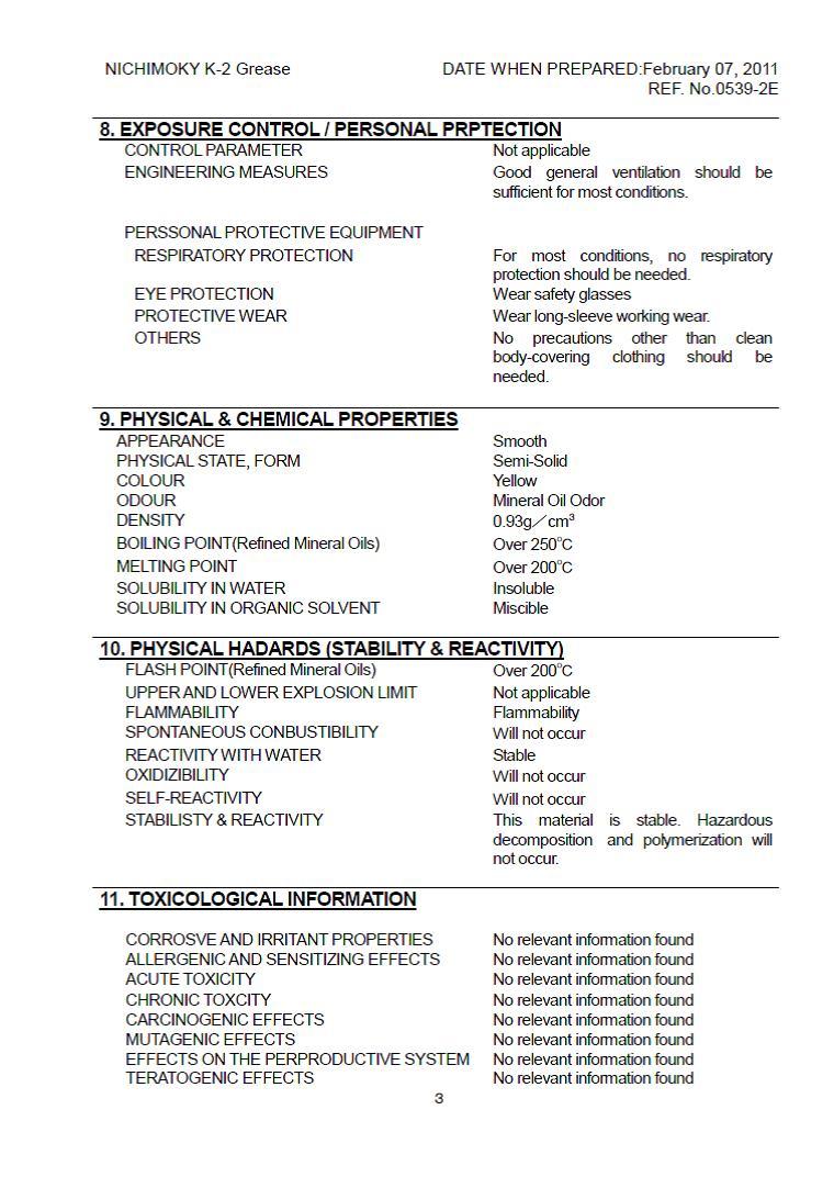
222 A-4
223 A-5
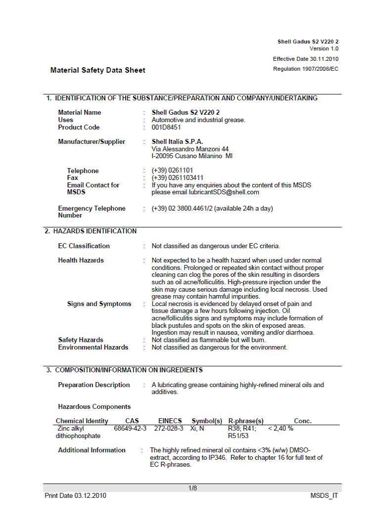
224 A-6
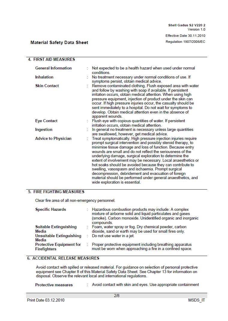
225 A-7
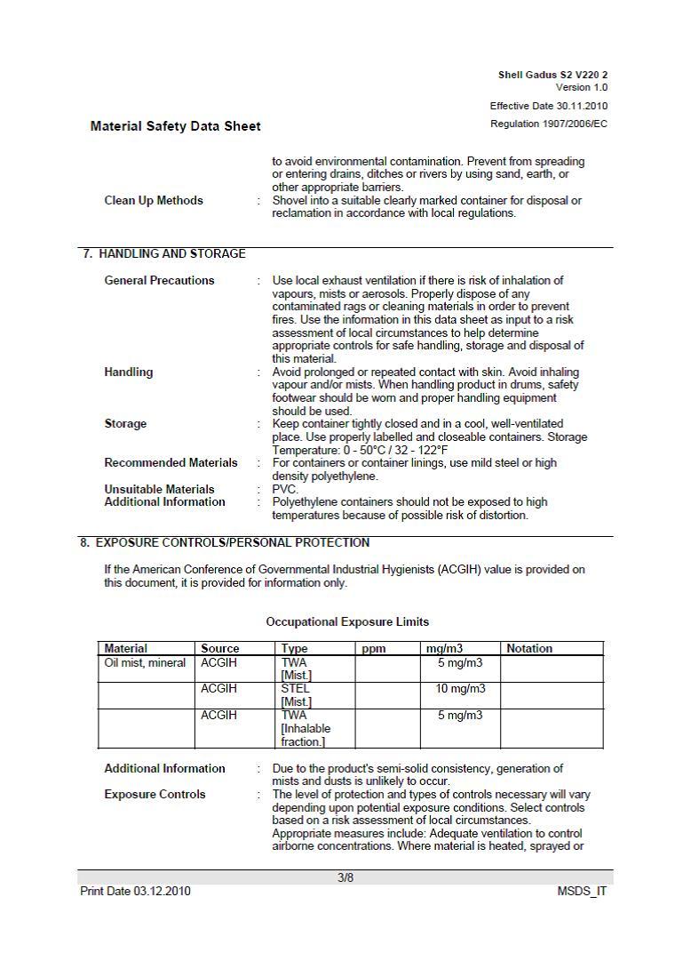
226 A-8
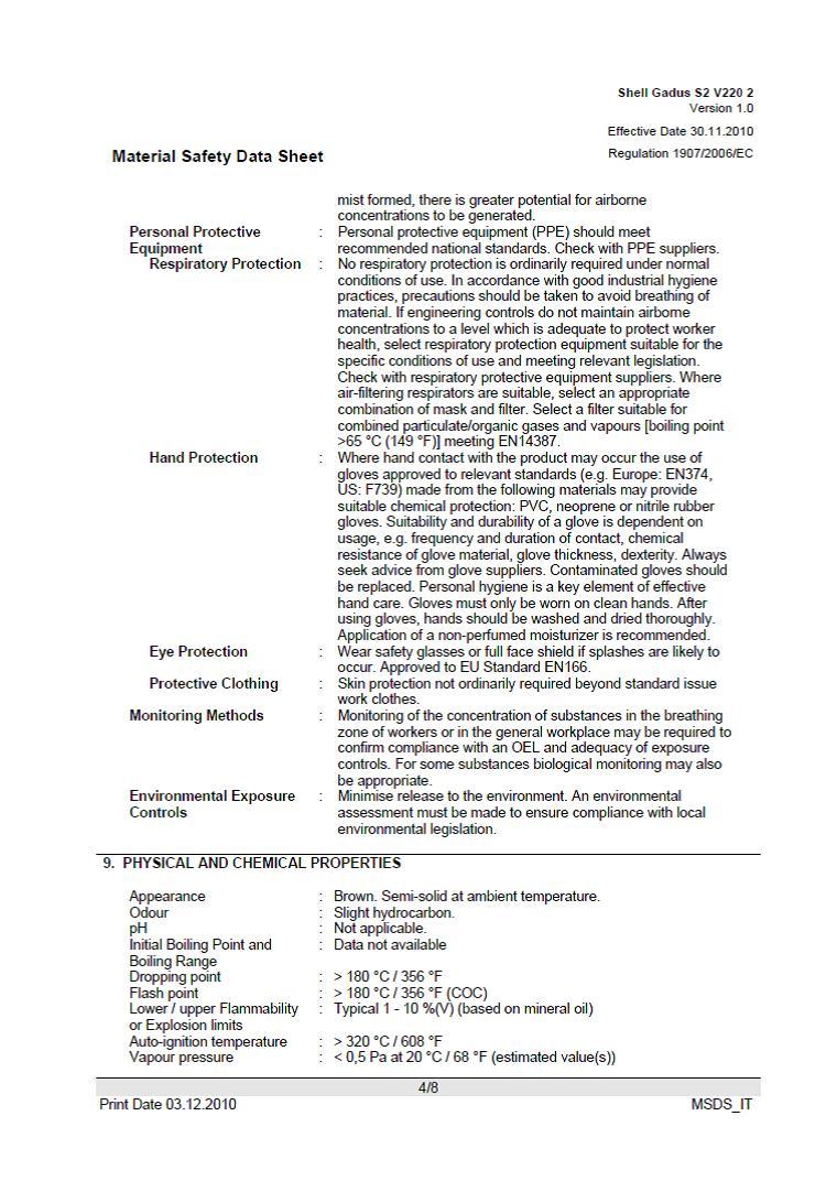
227 A-9
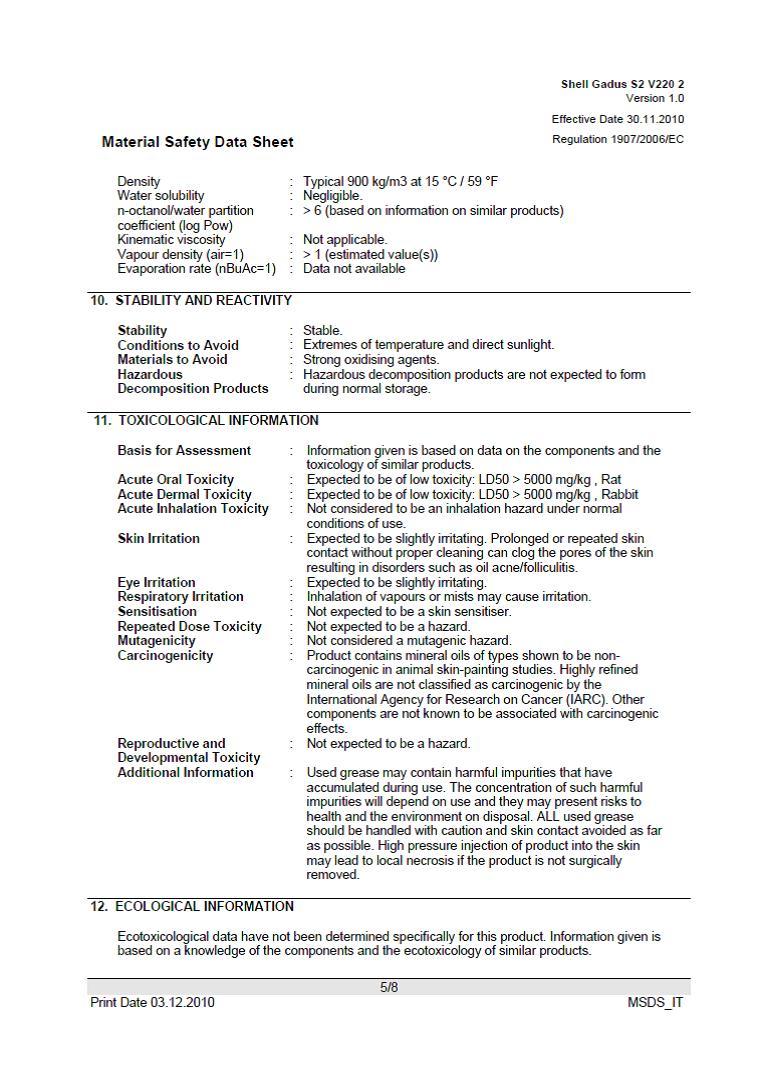
228 A-10
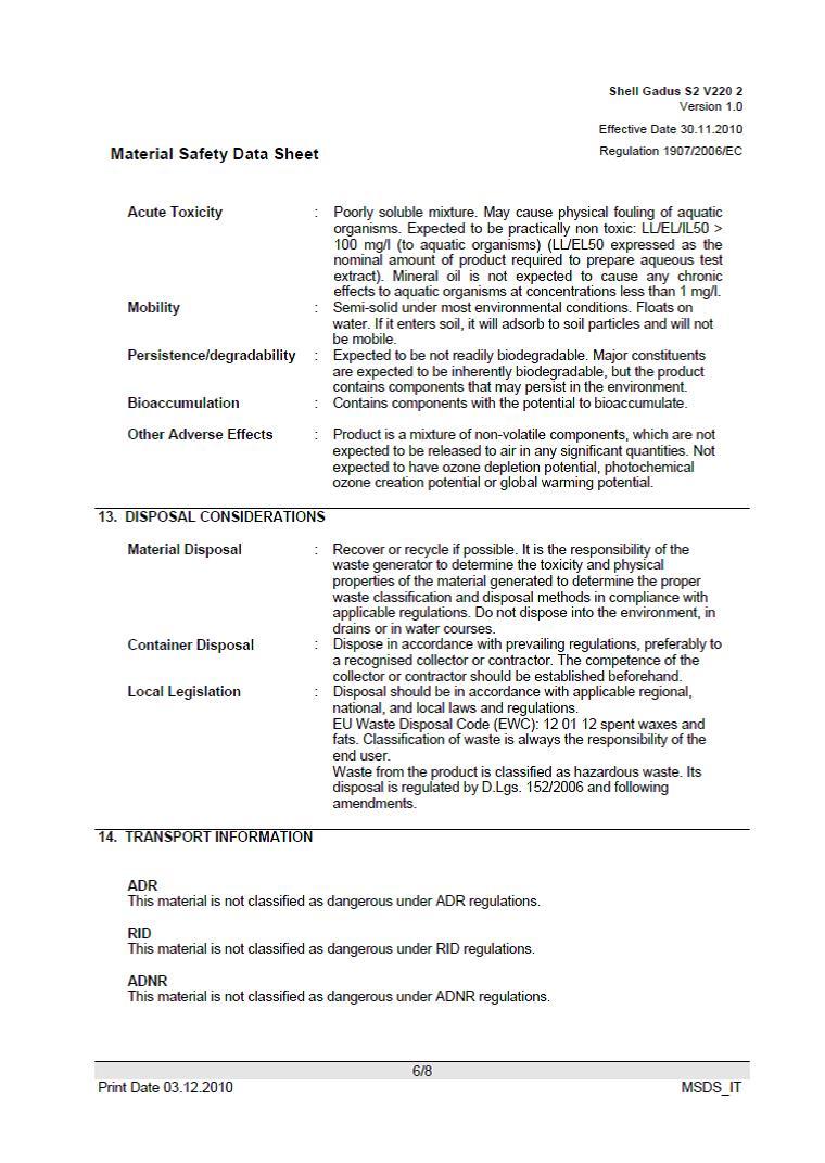
229 A-11
Laser Cutting Machine Safety Guide (For employers and employees)
") Laser Cutting Machine Safety Guide (For employers and employees) This safety guide is an English translation of Japanese safety guide based on Japanese laws and regulations. Please comply with your country's
Laser Cutting Machine Safety Guide (For employers and employees) This safety guide is an English translation of Japanese safety guide based on Japanese laws and regulations. Please comply with your country's
Stony Brook University Hospital Environmental Health & Safety Policy & Procedure Manual. EH&S 6-8 Original : 1/00 Revision Date: 3/16/15 Pages 6
 Title: Laser Safety Stony Brook University Hospital Environmental Health & Safety Policy & Procedure Manual EH&S 6-8 Original : 1/00 Revision Date: 3/16/15 Pages 6 PURPOSE: SCOPE: To protect University
Title: Laser Safety Effective Date: 9/91 Revision: 2/97 Number of Pages: 7
 Environmental Health and Safety Manual Policy Number: EH&S 6-8 Title: Laser Safety Effective Date: 9/91 Revision: 2/97 Number of Pages: 7 PURPOSE: SCOPE: To protect University employees against health
Fire Safety. Version 1.0
 This document is intended to provide basic safety guidelines for the Physical Plant Department at Community College of Allegheny County. The information provided in this guide may vary by site. Version
INDUSTRY WIDE LABOR-MANAGEMENT SAFETY COMMITTEE
 INDUSTRY WIDE LABOR-MANAGEMENT SAFETY COMMITTEE SAFETY BULLETIN #39 SAFETY GUIDELINES FOR USING FOAM(ED) PLASTICS IN SET AND PROP CONSTRUCTION The following recommendations are intended to give general
Facility Safety Rules Hazard Communication Emergency Procedures Fire Safety. Safety Orientation
 Facility Safety Rules Hazard Communication Emergency Procedures Fire Safety Safety Orientation Facility Safety Rules Report all hazards, unsafe acts, unsafe conditions and unsafe equipment to your Supervisor
Chapter 18 Welding Table of Contents
 Chapter 18 Welding Table of Contents 18.1 Foreword 18.2 Introduction 18.3 Applicability of Standard 18.4 Other Policies that Might Apply 18.5 Approved Areas for Welding and Cutting 18.6 Other Areas 18.7
SYNRAD Laser Safety 101
 SYNRAD Laser Safety 101 Version 2.1 Released June 2018 SYNRAD is a registered trademark of Novanta Corporation. Novanta Corporation 2018. All Rights Reserved. No reproduction without written authorization.
North Dakota State University Laser Safety
 North Dakota State University Laser Safety I. Introduction The laser represents a class of light emitting devices with unique characteristics. Some of these characteristics can result in significant hazards.
Mini-Rooter Operating Instructions
 Mini-Rooter Operating Instructions For 1-1/4 through 4 lines (30mm 100mm) Your Mini-Rooter is designed to give you years of trouble-free, profitable service. However, no machine is better than its operator.
General safety precautions English
 English A min (m 2 ) 550 530 540 510 520 490 500 470 480 450 460 430 440 410 420 390 400 370 380 350 360 330 340 310 320 290 300 270 280 250 260 230 240 210 220 190 200 170 180 150 160 130 140 110 120
General safety precautions English
 English A min (m 2 ) 550 530 540 510 520 490 500 470 480 450 460 430 440 410 420 390 400 370 380 350 360 330 340 310 320 290 300 270 280 250 260 230 240 210 220 190 200 170 180 150 160 130 140 110 120
GENERAL 2004 HVAC SYSTEMS. Manual HVAC System - Sorento SPECIFICATIONS. Fig. 1: Air Conditioner Specifications Courtesy of KIA MOTORS AMERICA, INC.
 Fig. 2: Blower & Evaporator Unit Specifications 2004 HVAC SYSTEMS Manual HVAC System - Sorento GENERAL SPECIFICATIONS AIR CONDITIONER Fig. 1: Air Conditioner Specifications BLOWER AND EVAPORATOR UNIT HEATER
Laser Safety. This Laser Safety Program applies to the acquisition, use, transfer, and disposal of all Class 3B and 4 lasers at UNC Asheville.
 Laser Safety The UNC Asheville laser safety program requires that all lasers and laser systems be operated in accordance with the American National Standards Institute (ANSI) Z136.1 2007, American National
Bloomsburg University of Pennsylvania Hot Work Safety Program Effective Date: July 1, 2015
 Bloomsburg University of Pennsylvania Hot Work Safety Program Effective Date: July 1, 2015 I. General Overview A. This program is to prevent injury, fire and unnecessary fire alarm activations in a building
PORTABLE HAND POWER THREADER 1/2-2
 PORTABLE HAND POWER THREADER 1/2-2 Read this Operator s Manual carefully before using this tool. Failure to understand and follow the contents of this manual may result in electrical shock, fire and/or
User Manual GV25 GV35 GV702. Company information: Original instructions GV12066 (1)
") User Manual Original instructions GV25 GV35 GV702 Company information: www.vipercleaning.eu info-eu@vipercleaning.com GV12066 (1) 2012-04-10 USER MANUAL ENGLISH TABLE OF CONTENTS Introduction... 4 Manual
User Manual Original instructions GV25 GV35 GV702 Company information: www.vipercleaning.eu info-eu@vipercleaning.com GV12066 (1) 2012-04-10 USER MANUAL ENGLISH TABLE OF CONTENTS Introduction... 4 Manual
R100 Oil-Less Refrigerant Recovery Unit
 R100 Oil-Less Refrigerant Recovery Unit Operation Manual 1 INTRODUCTION Welcome to simple, efficient refrigerant recovery with your new YELLOW JACKET Refrigerant Recovery Unit, R100. This unit combines
3-1/2 Gallon Parts Washer
 3-1/2 Gallon Parts Washer Model 38347 Assembly and Operating Instructions 3491 Mission Oaks Blvd., Camarillo, CA 93011 Copyright 1998 by Harbor Freight Tools. All rights reserved. No portion of this manual
Refrigerant Recovery Machine. Model No Operating Manual
 Refrigerant Recovery Machine Model No. 25700 Operating Manual Safety Precautions WARNING : TO PREVENT PERSONAL INJURY AND / OR EQUIPMENT DAMAGE, CAUTION - Risk of injury. This equipment should only be
WMHP Series R410a Heat Pump INSTALLATION INSTRUCTIONS
 WMHP Series R410a Heat Pump INSTALLATION INSTRUCTIONS **WARNING TO INSTALLER, SERVICE PERSONNEL AND OWNER** Altering the product or replacing parts with non authorized factory parts voids all warranty
Material Safety Data Sheet U.S. Department of Labor Occupational Safety and Health Administration
 Section I Company Information / Product Identification Manufacturer s Name Telephone Numbers MASS Systems / A Unit of Ameron Global, Inc. Emergency: 800-255-3924 4601 Littlejohn St. Information: 626-337-4640
D O U B L E A U G E R M O R TA R M I X E R OWNER S MANUAL
 D O U B L E A U G E R M O R TA R M I X E R OWNER S MANUAL WARNING: Read carefully and understand all INSTRUCTIONS before operating. Failure to follow the safety rules and other basic safety precautions
PORTABLE HAND POWER THREADER 1/2-2
 PORTABLE HAND POWER THREADER 1/2-2 Read this Operator s Manual carefully before using this tool. Failure to understand and follow the contents of this manual may result in electrical shock, fire and/or
SECTION 1-1 SAFETY PRECAUTIONS DOUBLE ARM MIXER CHAPTER 1: SAFETY
 SECTION 1-1 SAFETY PRECAUTIONS Peerless mixers are designed and built to operate as safety as possible. However, if the precautions and procedures explained in this manual are not followed at all times,
INSTALLATION INSTRUCTIONS
 2008 Lennox Industries Inc. Dallas, Texas, USA INSTALLATION INSTRUCTIONS CH33 Series Units EVAPORATOR COILS 505,264M (65484504) 05/08 Supersedes 10/07 Litho U.S.A. RETAIN THESE INSTRUCTIONS FOR FUTURE
Radiation and Laser Safety
 Radiation and Laser Safety Introduction The increased use of lasers in science classes may pose a potential hazard to students and teachers. With the proper safety precautions, the laser can be a valuable
DUST COLLECTOR OPERATION AND SAFETY INSTRUCTIONS FM230 CAUTION: READ THE INSTRUCTION MANUAL BEFORE USING THE APPLIANCE
 DUST COLLECTOR OPERATION AND SAFETY INSTRUCTIONS FM230 CAUTION: READ THE INSTRUCTION MANUAL BEFORE USING THE APPLIANCE MACHINE DATA: MOTOR: 1HP FAN DIAMETER 230mm INLET DIAMETER 100mm AIR SPEED 600CFM
V-220 / V-320 Heater Kits Installation Instructions TK IM (Rev. 0, 06/17)
") Installation Manual V-220 / V-320 Heater Kits Installation Instructions TK 56340-18-IM (Rev. 0, 06/17) Installation Manual V-220 / V-320 Heater Kits Installation Instructions TK 56340-18-IM (Rev. 0, 06/17)
Installation Manual V-220 / V-320 Heater Kits Installation Instructions TK 56340-18-IM (Rev. 0, 06/17) Installation Manual V-220 / V-320 Heater Kits Installation Instructions TK 56340-18-IM (Rev. 0, 06/17)
Accessories. Safety Warnings. Table of Contents
 Table of Contents Accessories...1 Safety Warnings...1 Work Area...2 Electrical Safety...2 Personal Safety...2 Power Tool Use and Care...3 Service...3 Hammer Safety Warnings...3 Usage...4 Changing Tools...4
PS-2/ES Automated pack & tag machine with IndES fastening system
 English Manual PS-2/ES Automated pack & tag machine with IndES fastening system Contents 1. Introduction 2. Important Safety Instructions 3. PS-2/ES 4. Unpacking the machine 5. Setting up the machine 6
TE 300-AVR. English Français Español Português
 TE 300-AVR English Français Español Português en fr es pt 1 2 3 4 5 6 7 8 9 TE 300-AVR en Original operating instructions....................................... 1 fr Mode d'emploi original............................................
General safety precautions English
 English 1 1 1.1 About the documentation The original documentation is written in English. All other languages are translations. The precautions described in this document cover very important topics, follow
ULTRA LOW TEMPERATURE FREEZER. User Manual
 ULTRA LOW TEMPERATURE FREEZER User Manual Note:Kaltis reserves the right to modify any parts of this manual without prior notice. 1. No part of this manual may be reproduced in any form, or translated
POLICY STATEMENT: Policy Number: Section 600 Physical Plant. Date Adopted: May 7, Date(s) Revised: September 4, 2012
 Revised: September 4, 2012") Policy Number: 600.8 Policy Title: Subject: Hot Work Program Section 600 Physical Plant Date Adopted: May 7, 2009 Date(s) Revised: September 4, 2012 Approved by: Daniel J. Bingham Dean/CEO Helena College
Policy Number: 600.8 Policy Title: Subject: Hot Work Program Section 600 Physical Plant Date Adopted: May 7, 2009 Date(s) Revised: September 4, 2012 Approved by: Daniel J. Bingham Dean/CEO Helena College
Outlines. 1. Introduction of Safety at Laboratories. 2. Emergency Situations. 3. Basic Safety Rules for All the Labs (Engg.
 Outlines 1. Introduction of Safety at Laboratories 2. Emergency Situations 3. Basic Safety Rules for All the Labs (Engg. And Science Labs) 4. Safety Rules for Engineering Labs I. Chemical Engineering Lab
Press Machine Safety Guide
 Press Machine Safety Guide (For employers and employees) This safety guide is an English translation of Japanese safety guide based on Japanese laws and regulations. Please comply with your country's laws
Rutgers Environmental Health and Safety (REHS)
") Rutgers Environmental Health and Safety (REHS) Program Name: Laboratory Laser Safety Program Responsible Executive: Executive Director of REHS Adopted: February 20, 2001 Reviewed/Revised: July 10, 2018
Rutgers Environmental Health and Safety (REHS) Program Name: Laboratory Laser Safety Program Responsible Executive: Executive Director of REHS Adopted: February 20, 2001 Reviewed/Revised: July 10, 2018
Fire Prevention Plan
 Fire Prevention Plan TABLE OF CONTENTS Section Title Page 1.0 Objective. 3 2.0 Background 3 3.0 Assignment of Responsibility.. 4 4.0 Plan Implementation..... 5 5.0 Types of Hazards...... 6 6.0 Training........
CONTRACTOR WHS HAZARD STANDARD LASER SAFETY EXTERNAL USE ONLY
 CONTRACTOR WHS HAZARD STANDARD LASER SAFETY EXTERNAL USE ONLY Principles in the Optus Contractor WHS management process CONTRACTOR MANAGEMENT STAGES PRINCIPLES THIS STANDARD REQUISITION Requisition WHS
RK-02 Multi Point Detector Operator s Manual
 65-2485RK-02 Multi Point Detector Operator s Manual Part Number: 71-0237RK Revision: A Released: 11/26/14 RKI Instruments, Inc. www.rkiinstruments.com WARNING Read and understand this instruction manual
Disposal Manual. m{zd{ 6. Capacitor( -ELOOP ) October 2012 Mazda Motor Corporation
 October 2012 Mazda Motor Corporation") Capacitor( -ELOOP ) Disposal Manual m{zd{ 6 Vehicle type in VIN : JM* GJ ****** 100001~ JM* GL ****** 100001~ RUM GJ ****** 100001~ October 2012 Mazda Motor Corporation 1 Capacitor disposal manual_gj_eng161128.xlsx
Capacitor( -ELOOP ) Disposal Manual m{zd{ 6 Vehicle type in VIN : JM* GJ ****** 100001~ JM* GL ****** 100001~ RUM GJ ****** 100001~ October 2012 Mazda Motor Corporation 1 Capacitor disposal manual_gj_eng161128.xlsx
WINDOW TYPE COOLING MODEL AKT7F AKT9F REVERSE CYCLE MODEL AKT7U AKT9U FUJITSU GENERAL LIMITED
 OPERATING MANUAL OPERATING MANUAL BEDIENUNGSANLEITUNG MODE D EMPLOI MANUAL DE FUNCIONAMIENTO MANUALE DI ISTRUZIONI ΕΓΧΕΙΡΙ ΙΟ ΛΕΙΤΟΥΡΓΙΑΣ MANUAL DE INSTRUÇÕES ROOM AIR CONDITIONER WINDOW TYPE COOLING MODEL
3.5-GALLON PARTS WASHER OWNER S MANUAL
 3.5-GALLON PARTS WASHER OWNER S MANUAL WARNING: Read carefully and understand all INSTRUCTIONS before operating. Failure to follow the safety rules and other basic safety precautions may result in serious
DUQUESNE UNIVERSITY. Laser Safety Program
 DUQUESNE UNIVERSITY Laser Safety Program Prepared by: Environmental Health and Safety Department TABLE OF CONTENTS Page Purpose 1 Scope 1 Introduction 1 Registration of Laser Systems 2 Laser Safety Training
FIRE SUPPRESSION TECHNICIAN
 REPAIRING AND REPLACING FIRE SUPPRESSION SYSTEMS FIRE SUPPRESSION TECHNICIAN Activity Hazard Identification Required Precautions 1. Driving to and from work site. 1. Motor vehicle accident; striking pedestrians,
ATD /8 Electric Drill
 ATD-10538 3/8 Electric Drill Tool specifications: Rated Voltage: (V) 120 Rated Frequency: (Hz) 60 Rated current: (A) 3.3 No-load Speed: (RPM) 0-2700 Speed Selection: Yes Right/Left Rotation: Yes Chuck
General safety precautions English
 English 1 1 Units are marked with the following symbol: 1.1 About the documentation The original documentation is written in English. All other languages are translations. The precautions described in
Automatic Water System Pump SERIES
 Automatic Water System Pump 42755 SERIES Automatic Water System Pump Purpose of this manual The purpose of this manual is to provide necessary information for product installation, operation and maintenance.
TE 2 TE 2-M TE 2-S. English Français Español Português
 TE 2 TE 2-M TE 2-S English Français Español Português en fr es pt 1 Printed: 15.12.2015 Doc-Nr: PUB / 5261122 / 000 / 00 2 3 4 5 Printed: 15.12.2015 Doc-Nr: PUB / 5261122 / 000 / 00 6 7 8 TE 2 TE 2-M TE
General Procedures: Materials Synthesis Lab 1358 CNAM/Toll
 STANDARD OPERATING PROCEDURE Updated: Jun 7, 2018 General Procedures: Materials Synthesis Lab 1358 CNAM/Toll The purpose of these Standard Operational Procedures (SOPs) is to define the standard set of
Operating Instructions
 Operating Instructions BA-003 Read and understand this manual before use. Keep this manual for future reference. CONFORMS TO UL STD.No.1017 Certified to CSA STD C22.2 No.243-10 For questions or concerns
PS /2 Inch Angle Grinder Assembly & Operating Instructions READ ALL INSTRUCTIONS AND WARNINGS BEFORE USING THIS PRODUCT.
 PS07214 4 1/2 Inch Angle Grinder Assembly & Operating Instructions READ ALL INSTRUCTIONS AND WARNINGS BEFORE USING THIS PRODUCT. This manual provides important information on proper operation & maintenance.
FEB 15 Rev C
 ORIGINAL INSTRUCTIONS Double-Action Hand Tool (DAHT) Lithium-Ion Battery-Powered Crimping Tool Kits 2217483-[ ] Customer Manual 409-32028 13 FEB 15 Rev C SAFETY PRES READ THIS FIRST!... 2 1. INTRODUCTION...
FIRE SAFETY. This easy-to-use Leaders Guide is provided to assist in conducting a successful presentation. Featured are:
 FIRE SAFETY This easy-to-use Leaders Guide is provided to assist in conducting a successful presentation. Featured are: INTRODUCTION: A brief description of the program and the subject that it addresses.
SECTION 1: STARTING 1.1 UNPACKING AND INSPECTION
 SECTION 1: STARTING 1.1 UNPACKING AND INSPECTION Upon receipt of the laser system, inspect the shipping containers for gross external damage. Unpack the unit and inspect for internal damage. If any damage
ELECTRIC AIR PUMP 130W INSTRUCTION MANUAL SPECIFICATIONS. ozito.com.au WHAT S IN THE BOX. Electric Air Pump. 3 x Inflation Adaptors
 WHAT S IN THE BOX ELECTRIC AIR PUMP 130W INSTRUCTION MANUAL SPECIFICATIONS Voltage: 220-240V ~50Hz Power: 130W Max. Current: 0.62A Max. Pressure: 0.6PSI Flow Rate: 440L/Min Inflation Time: Under 2min (double
ENGLISH (Original instructions) INSTRUCTION MANUAL. Demolition Hammer HM0810TA DOUBLE INSULATION. IMPORTANT: Read Before Using.
 INSTRUCTION MANUAL. Demolition Hammer HM0810TA DOUBLE INSULATION. IMPORTANT: Read Before Using.") ENGLISH (Original instructions) INSTRUCTION MANUAL Demolition Hammer HM080TA 00079 DOUBLE INSULATION IMPORTANT: Read Before Using. ENGLISH (Original instructions) SPECIFICATIONS Model HM080TA Blows per
ENGLISH (Original instructions) INSTRUCTION MANUAL Demolition Hammer HM080TA 00079 DOUBLE INSULATION IMPORTANT: Read Before Using. ENGLISH (Original instructions) SPECIFICATIONS Model HM080TA Blows per
Laser Use Registration & Application (L.U.R.)
") College of Science & Engineering San Francisco State University 1600 Holloway Avenue, TH323 San Francisco, California 94132-4163 (415) 338-6892 FAX (415) 338-6136 L.U.R. # COSE- Laser Use Registration
College of Science & Engineering San Francisco State University 1600 Holloway Avenue, TH323 San Francisco, California 94132-4163 (415) 338-6892 FAX (415) 338-6136 L.U.R. # COSE- Laser Use Registration
Fire Prevention Plan
 Fire Prevention Plan TABLE OF CONTENTS Section Title Page 1.0 Objective. 3 2.0 Background 3 3.0 Assignment of Responsibility.. 4 4.0 Plan Implementation..... 5 5.0 Types of Hazards...... 6 6.0 Training........
Instruction Manual Hydraulic Crimping Tool
 Instruction Manual Hydraulic Crimping Tool 902-480 Due to continuing improvements, actual product may differ slightly from the product described herein. Read this material before using this product. Failure
OWNER S MANUAL FOR AIR ADMIRAL VACUUM/PRESSURE STATION MODELS:
 OWNER S MANUAL FOR AIR ADMIRAL VACUUM/PRESSURE STATION MODELS: 79202-00 79202-05 79202-30 79202-35 Approval Agency s Model 79202-00 & 79202-05 Model 79202-30 & 79202-35 Not recommended for pumping acid,
ELECTRIC BODY SAW INSTRUCTIONS. Item #31660
 ELECTRIC BODY SAW INSTRUCTIONS Item #31660 The EASTWOOD ELECTRIC BODY SAW is great for use on virtually all metals including steel, aluminum, brass and more. Cuts wood, fiberglass and other materials with
WALLPAPER STEAMER. Model ASSEMBLY AND OPERATING INSTRUCTIONS
 WALLPAPER STEAMER Model 91098 ASSEMBLY AND OPERATING INSTRUCTIONS 3491 Mission Oaks Blvd., Camarillo, CA 93011 Visit our Web site at: http://www.harborfreight.com Copyright 2004 by Harbor Freight Tools.
User s Manual WALL MOUNT SERIES TABLE OF CONTENTS RA7730SS/RA77B30SS RA7736SS/RA77B36SS RA7742SS/RA77B42SS RA7748SS/RA77B48SS.
 TABLE OF CONTENTS 1 Table of Contents www.windsterhood.com Safety Information... 2 3 WALL MOUNT SERIES User s Manual RA7730SS/RA77B30SS RA7736SS/RA77B36SS RA7742SS/RA77B42SS RA7748SS/RA77B48SS NOTE: PLEASE
HG-2000E HEAT GUN WATTS
 HG-2000E HEAT GUN 2.000 WATTS EN - INSTRUCTIONS Carefully read the instructions for use before you start using the machine. drivenbycare www.orfit.com 1 2 6 8 7 2 8 450 C 300 C 6 A E FE 550 C PVC (hard)
7140 Dust Collector Owner s Manual
 7140 Dust Collector Owner s Manual Oliver Machinery M-7140 09/2011 Seattle, WA Copyright 2003 info@olivermachinery.net www.olivermachinery.net CONTENTS ADDITIONAL SAFETY RULES FOR DUST COLLECTOR... 3 SAFETY
User s Manual WS-63TB36SS WS-63TB42SS NOTE: PLEASE INSPECT HOOD IMMEDIATELY UPON RECEIVING. CLAIM OF DAMAGE AFTER 7 DAYS OF DELIVERY WILL BE DENIED.
 www.windsterhood.com User s Manual WS-63TB36SS WS-63TB42SS ISLAND SERIES NOTE: PLEASE INSPECT HOOD IMMEDIATELY UPON RECEIVING. CLAIM OF DAMAGE AFTER 7 DAYS OF DELIVERY WILL BE DENIED. This unit is designed
Workplace FIRE SAFETY
 Workplace FIRE SAFETY 18 1 FIRE! Fire claims the lives of over 5,000 people each year in the United States. Fire also causes thousands of disabling injuries, millions of dollars of property damage and
General safety precautions English
 General safety precautions General safety precautions English 1 General safety precautions 1 General safety precautions Units are marked with the following symbol: 1.1 About the documentation The original
Laser Safety Citations
 General 1. Lasers are classified appropriately Classify lasers and laser systems according to their relative hazards MSU Laser Safety Manual - Laser Classification, pg 9 2. Beam attenuator present A beam
LASER SAFETY. Class 2 and 2a - low power, low risk Class 2 and 2a lasers have low power and emit visible light. They will cause harm if viewed
 LASER SAFETY Laser is an acronym for light amplification by stimulated emission of radiation. Radiation in this case occurs in the portions of the electromagnetic field with insufficient energy to induce
Fire Extinguisher Training
 Fire Extinguisher Training The Fire Triangle Fire Safety, at its most basic, is based upon the principle of keeping fuel sources and ignition sources separate. The Fire Triangle Three things must be present
Salt Lake Community College FIRE EXTINGUISHER TRAINING
 Salt Lake Community College Legal Basis for Training Occupational Safety and Health Administration (OSHA) Occupational Safety and Health Standards 29 CFR Part 1910 Subpart L Fire Protection Standard 1910.157
1998 Expedition/Navigator Workshop Manual
 Page 1 of 8 SECTION 412-00: Climate Control System - General Information 1998 Expedition/Navigator Workshop Manual DESCRIPTION AND OPERATION Procedure revision date: 02/11/2000 Climate Control System WARNING:
Climate Control System
 Page 1 of 13 SECTION 412-00: Climate Control System General Information DESCRIPTION AND OPERATION 1998 Mark VIII Workshop Manual Climate Control System Cautions and Warnings WARNING: To avoid accidental
MME Standard Operating Procedure (SOP)
") MME Standard Operating Procedure (SOP) Name Femtosecond Laser Description Coherent Legend Elite, Ultrafast Amplifier Laser Systems Location E3-2168 SOP Creation Date 2015-03-08 SOP Created By Paola Russo
MME Standard Operating Procedure (SOP) Name Femtosecond Laser Description Coherent Legend Elite, Ultrafast Amplifier Laser Systems Location E3-2168 SOP Creation Date 2015-03-08 SOP Created By Paola Russo
DEHUMIDIFIER OWNER S MANUAL. Read this manual carefully before operating the appliance and retain it for future reference.
 OWNER S MANUAL DEHUMIDIFIER ESPAÑOL FRANÇAIS Read this manual carefully before operating the appliance and retain it for future reference. Model : UD701KOG1 P/NO : MFL68026017 www.lg.com TABLE OF CONTENTS
OPERATION & MAINTENANCE MANUAL TX600
 OPERATION & MAINTENANCE MANUAL TX600 RTI TECHNOLOGIES, INC. 4075 East Market Street York, PA 17402 Manual P/N 035-80118-00 (Rev B) ! TABLE OF CONTENTS! TX600 Before Using Page 2 Safety Precautions Page
What are the four things that must be present at the same time to produce fire?
 What are the four things that must be present at the same time to produce fire? Enough oxygen to sustain combustion, Enough heat to raise the material to its ignition temperature, Some sort of fuel or
OPERATION & MAINTENANCE MANUAL TC670
 OPERATION & MAINTENANCE MANUAL TC670 Refrigerant Management Center (Convertible For Use With R12 or R134a) RTI TECHNOLOGIES, INC. 4075 East Market Street York, PA 17402 Manual P/N 035-80342-02 TC670 CONVERTIBLE
14. The center port of the manifold is used for evacuation, charging and refrigerant recovery.
 HET- 190 ESL Support page 1 CORE Basic Refrigeration Circuit 1. Liquid refrigerant boils in the evaporator. Heat is absorbed. The heat energy absorbed converts refrigerant liquid into vapor. 2. Refrigerant
XC-18. NOTE: *Machine shown without Lift-Up Safety Guard. This guard is included with machine. Machine should not be operated without this guard.
 XC-18 NOTE: *Machine shown without Lift-Up Safety Guard. This guard is included with machine. Machine should not be operated without this guard. EXTREMA MACHINERY COMPANY, INC. PO BOX 1450, ALBANY, LOUISIANA
Laser Use at Subaru Telescope (NAOJ) Laser Safety Policy
 Laser Safety Policy") Laser Use at Subaru Telescope (NAOJ) Laser Safety Policy 1. Introduction This program applies to all lasers and laser systems operated by Subaru Telescope. This program maintains compliance with ANSI Z136.1-2007
Laser Use at Subaru Telescope (NAOJ) Laser Safety Policy 1. Introduction This program applies to all lasers and laser systems operated by Subaru Telescope. This program maintains compliance with ANSI Z136.1-2007
User s Manual ISLAND SERIES TABLE OF CONTENTS RA-7630SS RA-7636SS RA-7642SS RA-7648SS. Table of Contents. Safety Information...
 - TABLE OF CONTENTS Table of Contents 1 www.windsterhood.com Safety Information... 2 3 ISLAND SERIES User s Manual RA-7630SS RA-7636SS RA-7642SS RA-7648SS NOTE: PLEASE INSPECT HOOD IMMEDIATELY UPON RECEIVING.
Laser Safety Management
 Properties of Laser light Laser Safety Management Danny Fok Monochromatic (single wavelength) Directional (almost parallel low angular divergency) Coherent (in phase) Pulse or continuous Beam can be focused
Read this Safety Guide first.
 LCD Projector User's Manual - Safety Guide Thank you for purchasing this projector. About The Symbols Read this Safety Guide first. Before using, read the user manuals for this projector to ensure correct
TE 40 TE 40-AVR English
 TE 40 TE 40-AVR English 1 Information about the documentation 1.1 About this documentation Read this documentation before initial operation or use. This is a prerequisite for safe, trouble-free handling
West Virginia University Laser Safety Program
 I. Statement, Purpose, and Scope A. Statement: The University is committed to providing a safe and healthful workplace; this includes evaluating and taking action to prevent laser related exposures. B.
Directive on Laser Safety. NRC Occupational Safety and Health Manual
 Directive on Laser Safety NRC Occupational Safety and Health Manual Directive Information TYPE OF DIRECTIVE Directive and Standard DATE OF ISSUE 6 September 2008 FREQUENCY OF REVIEW Five Years DIRECTIVE
University of California, Davis Laboratory Self-Inspection Checklist
 University of California, Davis Laboratory Self-Inspection Checklist Principal Investigator/Laboratory Supervisor: Laboratories Reviewed: Date: Reviewer: Revised 11/2014 I. SAFETY PROGRAM ADMINISTRATON
HNC-120BE-L/R-B HNC-150BE-L/R-B HNC-180BE-L/R-B HNC-210BE-L/R-B COUNTER SHOWCASE MODEL SERVICE MANUAL HOSHIZAKI
 NO. S051-800 ISSUED: MAR. 26, 2010 REVISED: HOSHIZAKI COUNTER SHOWCASE MODEL HNC-120BE-L/R-B HNC-150BE-L/R-B HNC-180BE-L/R-B HNC-210BE-L/R-B SERVICE MANUAL IMPORTANT This manual should be read carefully
Rice University Laser Safety Manual
 Rice University Laser Safety Manual Environmental Health and Safety MS 123 P.O. Box 1892 Houston, TX 77251-1892 January 2014 RICE UNIVERSITY 1 Introduction The objective of the Rice University Laser Safety
Lamorinda CERT - Unit 2 09/15/2016
 Contra Costa County CERT Program Unit 2 Fire Safety Released: 15 September 2016 Community Emergency Response Team Personal safety is ALWAYS the number one priority Work as a team Wear personal protective
20-GALLON MOBILE PARTS WASHER OWNER S MANUAL
 20-GALLON MOBILE PARTS WASHER OWNER S MANUAL WARNING: Read carefully and understand all INSTRUCTIONS before operating. Failure to follow the safety rules and other basic safety precautions may result in
100T Electric Shop Press
 100T Electric Shop Press Operation Manual 1 Important Information 1.1 Safety Information 1.1.1 Hazard Symbols Used in the Manuals This manual includes the hazard symbols defined below when the operations
Operator s Manual S-333. Automated Soil Compactor. Version 3.3. Durham Geo Slope Indicator 2175 West Park Court Stone Mountain, GA USA
 Automated Soil Compactor S-333 Operator s Manual Version 3.3 Durham Geo Slope Indicator 2175 West Park Court Stone Mountain, GA 30087 USA Phone: 800-837-0864 or +1.770.465.7557 Fax: 770.465.7447 e-mail:
HEAVY REFRIGERATION MECHANIC// SR. HEAVY REFRIGERATION MECHANIC
 HEAVY REFRIGERATION MECHANIC// Activity Hazard Identification Required Precautions 1. Driving to and from work site. 1. Motor vehicle accident; striking pedestrians, bicyclists, or individuals using rollerblades.
ENGLISH (Original instructions) INSTRUCTION MANUAL. Belt Sander DOUBLE INSULATION. IMPORTANT: Read Before Using.
 INSTRUCTION MANUAL. Belt Sander DOUBLE INSULATION. IMPORTANT: Read Before Using.") ENGLISH (Original instructions) INSTRUCTION MANUAL Belt Sander 990 99 00336 DOUBLE INSULATION IMPORTANT: Read Before Using. ENGLISH (Original instructions) SPECIFICATIONS Model 990 99 Belt size 76 mm x
ENGLISH (Original instructions) INSTRUCTION MANUAL Belt Sander 990 99 00336 DOUBLE INSULATION IMPORTANT: Read Before Using. ENGLISH (Original instructions) SPECIFICATIONS Model 990 99 Belt size 76 mm x
Risk Management Department. Fire Extinguishers
 Risk Management Department Fire 1 Introduction to Fire Every school facility is equipped with fire extinguishers for staff to use to suppress fires. Used properly, a fire extinguisher can be an effective