Operations and Maintenance Manual
|
|
|
- Vernon Wilson
- 5 years ago
- Views:
Transcription

1 IMPORTANT: READ THIS MANUAL THOROUGHLY BEFORE INSTALLING AND OPERATING UNIT. INSURE THERE IS ALWAYS LUBRICATING OIL IN THE FRONT FILTER LUBRICATOR FOR THE FLUID PUMP AIR MOTOR. CHECK OIL LEVEL REGULARLY AND REFILL Phoenix C4XA Compressed Air Driven Membrane Based Portable Lube and Hydraulic Oil Purifier and Dehydrator Cart Operations and Maintenance Manual Rev 1-PHXADNL KB MSC Filtration Technologies 198 Freshwater Blvd Enfield, CT Phone :
2 INDEX PAGE 1 SECTION 1: SPECIFICATIONS PAGE 2 4 SECTION 2: DESCRIPTION AND OPERATION PAGE 5 7 SECTION 3: COMPONENT LIST AND DESCRIPTION PAGE 7 SECTION 4: CRANE RIGGING PAGE 9-12 SECTION 5: INSTALLATION AND STARTUP PROCEDURE PAGE SECTION 6: OPERATION AND OPERATIONAL CHECK LIST PAGE 16 SECTION 7: SPARE PARTS PAGE 17 SECTION 8: OIL FLUSHING PROCEDURE PAGE 18 SECTION 9: DATA SHEETS
3 SECTION 1 PHOENIX SPECIFICATIONS PAGE 1 OF 20 FLOW RATE: MAX OPERATING Oil VISCOSITY VARIABLE GPM AT 8 GPM 3 cst to 1000 cst AT 4 GPM - 3 cst to 3000 cst FLUID/OIL COMPATIBILITY MAX RECOMMENDED OUTLET PRESSURE MIN/MAX OPERATING AMBIENT TEMP MIN/MAX STORAGE TEMP MIN/MAX OPERATING FLUID TEMP EMPTY WEIGHT INLET/OUTLET CONNECTIONS MINERAL BASED, PAO AND POLYOLESTER (Phosphate Ester Membrane Optional) 20 PSIG 1 50 C C - 15C 80 C 250 LBS 1 Male JIC DIMENSIONS 20 W X 22 D X 51 H UTILITIES OILLESS COMPRESSED AIR PSIG PARTICULATE REDUCTION ISO 16/14/12 SCFM USAGE 4 GPM 30 SCFM SCFM USAGE 8 GPM 50 SCFM WATER REDUCTION (OIL TEMP, RESERVOIR SIZE & WATER < 50 PPM INGRESSION LEVEL DEPENDENT)


4 SECTION 2: PAGE 2 OF 20 Compressed Air Driven Phoenix Portable Lube and Hydraulic Membrane Oil Purifier and Dehydrator (Description and Operation) The Phoenix oil purifier is a compact and portable oil purifier car and membrane vacuum oil dehydrator with the capability to remove particulate along with free, emulsified and dissolved water from lube and hydraulic systems of between 20 and 2000 gallons. It is completely driven by compressed air and requires no electric hookup. Because it is driven by compressed air the variable speed air motor and fluid pump can be adjusted manually to flows of between 1 and 8 gpm depending on the oil viscosity being filtered. The Phoenix utilizes a cutting edge maintenance free hollow fiber membrane bundle to remove water contamination from oil. Moisture is pulled out of the oil by a vacuum as wet oil passes across the outside of the membrane. A vacuum created by a supplied air driven venturi vacuum generator pulls moisture through the membrane where it is expelled as water vapor from the vacuum generators exhaust port. Water levels as low as 25 ppm are achievable depending on oil sump size and water ingression levels. This cutting edge technology has no limit to the quantity of water it can remove and requires minimal maintenance and operator attention. It should provide years of worry and trouble free operation before replacement. IMPORTANT NOTE: The membrane bundle is not serviceable in the field and should be returned for replacement when its useful life is complete. Never try to disassemble the membrane housing in the field or damage to the bundle may occur. Figure 1
 which is variable speed and can be controlled by setting (item 5) filter, regulator, lubricator to between 10-20 psig.")
5 (SECTION 2: Description and Operation - Continued) PAGE 3 OF 20 Figure 2 Oil is pumped into the Phoenix Cart by (item 3) a 4-8 gpm variable flow gear pump with an integrated (item 4) 65 psid built in relief valve. This gear pump is driven by an air motor (item 2) which is variable speed and can be controlled by setting (item 5) filter, regulator, lubricator to between psig. The speed of the motor can then be adjusted up or down by adjusting the throttle valve (item 20) to your desired oil pumping speed of between 4 and 8 gpm. Oil then flows into (item 6) a non-bypass particulate 7-micron beta 2000 spin on filter. There is a visual filter plugged indicator on the filter housing to tell when the filter element is plugged. If the filter plugs fully and is not replaced, then pressure relief will occur through (item 4) the fluid pump 65 psid relief valve and flow out of the Phoenix will cease. (Item 1) is a vacuum gauge which shows the inlet vacuum that the fluid pump is pulling. A vacuum reading above 25 is an indication of restriction in the fluid line. To prevent cavitation and potential damage to the fluid pump never run the Phoenix for prolonged periods of time with a vacuum reading above 25 on (Item 1). Increase suction hose size, reduce hose length or reduce flow velocity to reduce suction vacuum. Oil then passes into (item 14) the maintenance free and non-replaceable water removal membrane. A 10 psid spring loaded check valve (Item 7) is piped in parallel with the water removal membrane housing to provide pressure relief across the membrane bundle in the event of excess differential pressure. The membrane housing may handle up to 150 psig of total pressure however (Item 7) limits the total pressure drop possible across the membrane bundle to about 10 psid. This total pressure may be read from (item 9) a psig liquid filled pressure gauge installed on the back of the Phoenix purifier.

6 (SECTION 2: Description and Operation - Continued) PAGE 4 OF 20 After oil enters the membrane housing it is forced across the water removal membrane bundle and then exits the housing. Water is removed from the oil as it passes across the membrane. If the spring loaded bypass (item 7) is open, then partial flow from the membrane housing will recombine with partial non dewatered oil passing through the check valve. Both combined flows exit the purifier and return to the oil reservoir through (item 8) - a sight glass with a spinning oil flow indicator. A vacuum is generated by the (item 16) maintenance free vacuum venturi which pulls atmospheric sweep air through (item s 11,12 &13) the (vent filter, vacuum control valve and leak prevention check valve) and then through the center of the hollow fiber membrane. (Item 18) is a filter pressure regulator where shop air of a minimum psig is connected. The shop air is what generates the vacuum in the venturi (item 16). (Item 15) An air eliminator is installed between the membrane housing and vacuum generator in order to prevent any large amounts of oil leakage to the vacuum side in the unlikely event that the membrane is compromised. The air eliminator (Item 15) and the check valve installed (Item 13) allow the Phoenix to automatically seal itself completely off in the unlikely event of a membrane break or rupture. The total vacuum generated by (Item 16) vacuum generator is controlled by maintaining psig on the regulator (item 18) and manually throttling down on the control valve (item 12) and may be read in inches of mercury on the vacuum gauge (item 10). Vacuum is typically set between 25 and 27 of mercury but may vary as water levels in the oil rise and fall. Do not close the control valve (item 12) completely since there is always some sweep air needed for efficient water removal. There is a sight glass and drip leg located on the membrane housing in order to drain any potential condensation or small amounts of oil that can get through the membrane from the line. Figure 3

7 PAGE 5 OF 20 SECTION 3: Component Lists and Description Figure 4 Figure 5 Figure 6


8 SECTION 3: Component Lists and Description Continued PAGE 6 OF 20 Figure 7 Figure 8 Figure 9
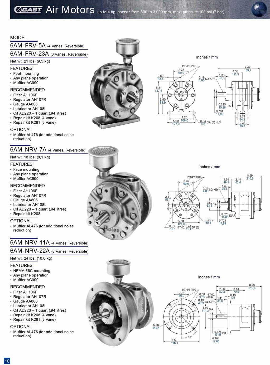
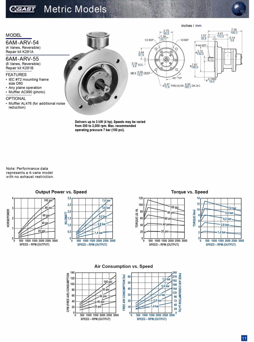
9 SECTION 3: Component Lists and Description Continued PAGE 7 OF 20 Item Description 1 Compound Vacuum Pressure Gauge Reads Suction Pressure to Fluid Pump 2 Variable Speed Fluid Pump Air Motor Compressed Air Driven Gast Model 6AM-FRV Gear Pump Variable Flow 1-8 GPM 4 Integrated 65 PSIG Pump Relief Valve. Relieves back to suction if upstream pressure increases above 65 PSIG. 5 Air Motor Filter, Regulator, Lubricator. Set Pressure to between PSIG. Monitor Oil Level Regularly only use SAE 10 Pneumatic Lube Oil Only. See Parts List. 6 Non Bypass Particulate Filter. 7 micron Beta 2000 with integrated filter plugged indicator. Indicates plugged above 35 psid of differential pressure. Only use filter replacements recommended in this manual (see part list) or warranty may be voided psid membrane bypass check valve. 8 Spinning Oil Flow Indicator Sight Glass Outlet Flow of Phoenix. 9 Water Removal Membrane Upstream Pressure Gauge 10 Vacuum Gauge Set Vacuum Side Breather Filter See Spare Parts for Replacement Replace 12 Months 12 Vacuum Adjustment Valve See Item 10 Vacuum Gauge when Adusting. 13 Back Flow Preventer Check Valve 14 Water Removal Membrane Housing 15 Oil Leak Preventer Air Eliminator 16 Water Removal Vacuum Generator Venturi 17 Water Removal Vacuum Generator Compressed Air Shut Off Valve. 18 Water Removal Vacuum Generator Compressed Air Pressure Regulator and Filter. Set to PSIG 19 Fluid Pump Air Motor Compressed Air Supply Shut Off Valve 20 Fluid Pump Air Motor Variable Speed Control Valve. Adjusts speed of fluid pump air motor. 1-8 gpm at SCFM 21 Inlet Oil Sample Valve Upstream of Particulate Filter 22 Air Motor Muffler Gast Model Number AL Vacuum Side Condensate Drain Valve Condensed Moisture and small amounts of oil that may get through membrane. Turn off Unit and Check Intermittently.

10 Section 4: Crane Rigging PAGE 8 OF 20 To lift unit with a crane connect strap from this point figure 11 only! Figure 11

11 Section 5: Installation and Startup Procedure IMPORTANT PAGE 9 OF 20 DO NOT CONNECT THE PHOENIX PURIFIER OUTLET LINE TO ANY POINT OR PRESSURE LINE WHERE THE BACK PRESSURE COULD EXCEED 20 PSIG OR DAMAGE TO THE MEMBRANE BUNDLE COULD OCCUR AND REPLACEMENT MAY BE NECESSARY. IT IS IDEAL TO CONNECT THE RETURN LINE OF THE PHOENIX TO A POINT OF LOWEST PRESSURE AS POSSIBLE SUCH AS ON A T DOWNSTREAM OF A BREATHER FILTER There are several ways to connect the Phoenix membrane purifier to a reservoir with some being better than others. Figures 10 shows two ideal ways since they both allow suction from the bottom of the reservoir where water and particulate can collect and return to the top away from the suction. This provides the maximum turnover of oil while the siphon breaks provide a level of safety in the event of a hose or fitting break/leak preventing the possibility of accidentally completely draining the reservoir. The return pipe should be unobstructed and end below the oil line to prevent aeration of the oil upon return to the reservoir. Figure 10


12 Section 5: Installation and Startup Procedure Continued PAGE 10 OF 20 STEP 1: AIR MOTOR LUBRICATOR IMPORTANT BEFORE STARTIING UNIT Allways insure there is adequate oil level in the air motor lubricator. Check this level regularly and shut down unit and refil oil as necessary. See spare parts for the correct oil type. Only use SAE 10 Pneumatic Lubricating Oil. Insure that there is atleast 1 drip of oil per minute seen in the see through knob at the top of the lubricator. Failure to do so will lead to damage to the air motor. STEP 2: SUPPLY HOSE CONNECTION Use at minimum 1 full vacuum rated hydraulic hoses for oil suction and return. In the event of viscocity above 1500 cst then 1.5 hoses may be required to minimize restriction at suction to purifier. Connection to Purifier is 1 JIC so hoses shoule have 1 JIC swivel. Tighten thouroghly to insure there are no leaks. Open all oil supply valves both suction and return from oil reservoir. STEP 3: AIR VALVE START POSTIONS 1. Close Air Motor Speed Adjustment Valve all the way. 2. Insure Upstream Oil Sample Valve is Closed 3. Close Vacuum Venturi Air Supply Valve


13 Section 5: Installation and Startup Procedure Continued PAGE 11 OF 20 STEP 4: AIR VALVE POSTIONS Cont 1. Open Main Air Motor Air Supply Valve STEP 5: CONNECT COMPRESSED AIR Connect main compressed air source that can provide atleast psig of oilless compressed air at a continuous flow of atleast 30 SCFM. Use the correct size and pressure air hoses and connection types needed to handle pressure. STEP 6: Pressure Regulator Settings. 1. Set Vacuum Venturi Regulator to between psig to insure maximum potential water removal. 2. Set Air Motor Regulator to between psig see motor flow chart on next page for desired oil flow vs pressure settings.


14 Section 5: Installation and Startup Procedure Continued STEP 7: VACUUM ADJUSTMENT PAGE 12 OF Open Vacuum Venturi Air Supply Valve. Insure pressure on regulator maintains psig. 2. Adjust Vacuum Adjustment Valve till Vacuum Gauge reads 27. Do not close valve all the way since some sweep air is required for maximum water removal membrane efficiency. Vacuum level will vary naturally depening on how much water is being removed between 24 and 27 during operation. STEP 8: FLUID PUMP FLOW START Open Air Motor Flow Control Valve and inspect outlet spinning flow indicator for oil flow. It may take a minute or two for flow to be present. See estimated flow vs pressure chart below. This flow will need to be adusted over time as the particulate filter plugs and backpressure occurs on the pump. As there is more back pressure there will need to be more air pressure adjusted to the air motor to keep turning at the same speed. EXPECTED PHOENIX OIL FLOW WITH 0 SYSTEM BACKPRESSURE AND FLOW CONTROL VALVE COMPLETELY OPEN. PRESSURE REGULATOR SETTING APPROXIMATE OUTLET OIL FLOW AIR USAGE SCFM 10 PSIG 4 GPM 30 SCFM 20 PSIG 6 GPM 45 SCFM 35 PSIG 8 GPM 50 SCFM


15 Section 6: OPERATION AND MAINTENANCE PAGE 13 OF 20 INSPECT LUBRICATOR OIL FILL PORT REGULARLY Inpect Clear Knob on top of air motor lubricator to insure atleast 1 drip of oil per minute is occuring when purifier is running. Close Air Motor air supply valve and insure pressure gauge on regulator goes to 0. Then refill lubricator with SAE 10 Pneumatic Oil when level reaches critical. Refill by removing slotted gray cap ontop of lubricator. Replace cap when done. INSPECT PARTICULATE FILTER INDICATOR REGULARLY There is a particulate filter plugged indicator with a white indicator which will move from green to red as the particulate filter plugs. Check regularly and replace element when necessary or every 6 months of usage whichever comes first. FILTER ELEMENT REPLACEMENT PROCEDURE It is recommended that the Phoenix be pumped out before the element is changed inorder to limit oil spillage. To pump out 1. Shut down oil flow. 2. Disconnect Supply Hose From Reservoir 3. Disconnect any Quick Disconnect Fittings from hose so to allow air to be pumped through Phoenix 4. Start oil flow and allow phoenix to pump out back to reservoir for approximately 2-3 minutes. Do not run fluid pump for more than 5 minutes dry. 5. Stop Oil Flow Again. 6. Use a strap wrench to remove spin on filter 7. Lubricate top oring of new spin on filter element. 8. Thread on new filter making sure proper alignment so not to strip threads on head. 9. Tighten Snug. 10. Restart Phoenix.

 1. Vacuum Gauge 24")

16 Section 6: OPERATION AND MAINTENANCE Continued PAGE 14 OF 20 Inspection Checklist Date Completed Time Completed Location Measurement Lubricator Oil Level - (Full, 3/4,1/2,1/4,Empty) Lubricator Drip Rate/Minute (Note watch clear knob ontop of lubricator 1 Drip per minute minimum) 1. Vacuum Gauge HG Recommended. 2. Pump Inlet Gauge Less than 25 HG Recommended 3. Membrane Pressure Gauge Less than 20 PSIG Recommended 1. Vacuum Air Regulator PSIG Recommended. 2. Fluid Pump Air Regulator PSIG Recommended
 Note: Spinning Indicator may not spin even when there is oiil flow if oil is cold and thick.")
 Condensation Drain Note: Shut of Vacuum Air Supply to occasionally open condensation drain valve.")
17 Section 6: OPERATION AND MAINTENANCE Continued PAGE 15 OF 20 Inspection Checklist Date Completed Time Completed Location Measurement Spinning Flow Indicator: (Spinning, Not Spinning) Note: Spinning Indicator may not spin even when there is oiil flow if oil is cold and thick. In this case check pump inlet gauge to see if there is vacuum/suction on gauge which would also indicate flow. Filter Plugged Indicator (Green, Middle, Red) Condensation Drain Note: Shut of Vacuum Air Supply to occasionally open condensation drain valve. There may be a little oil drain from the system or potentially condensed water. However if large amounts of oil are present contact your Phoenix Sales Representative.
18 Section 7: RECOMMENDED SPARE PARTS PAGE 16 OF 20 PART NUMBER MSCP MSCAD220 DESCRIPTION 7 MICRON PARTICULATE FILTER ELEMENT BLUE SPIN ON 1 QUART OF SAE 10 PNEUMATIC LUBRICATING OIL RECOMMENDED REPLACEMENT AS NEEDED OR EVERY 6 MONTHS WHATEVER COMES FIRST AS NEEDED CHECK OIL LEVEL REGULARLY AND REFILL MSCK208 AIR FLUID PUMP MOTOR REPAIR KIT RECOMMENDED EVERY 2 YEARS OF OPERATION SEE MOTOR INSTRUTIONS IN NEXT SECTION. ALONG WITH ONLINE VIDEO INSTRUCTIONS. FS VACUUM BREATHER FILTER EVERY 6 MONTHS 1 YEAR
19 Section 8: Oil Flushing Procedure PAGE 17 OF 20 IT IS RECOMMENDED THAT WHEN USING THE PHOENIX WITH MORE THAN ONE TYPE OF OIL THAT IT BE FLUSHED OUT BEFORE CHANGING TO ANOTHER OIL. THIS WILL PREVENT OIL CROSS CONTAMINATION IN RESERVOIRS. STEP 1 STEP 2 STEP 3 - STEP 4 - Close air supply valve to fluid pump motor to stop oil flow through phoenix. Disconnect inlet suction hose from oil reservoir. Remove any quick disconnect hydraulic Coupling from end of hose if used so that air can be pumped through Phoenix. Leave outlet hose connected to oil reservoir so any oil in Phoenix can be pumped Back to reservoir without loss. Open air supply valve to fluid pump motor and allow oil to pump out and back into reservoir. Watch outlet oil flow sight glass (see page 6 item 8 figures 8) till there is no more oil coming out. Run for 2 minutes max. STEP 5 - Place Bucket under membrane housing drain valve (Page 6, Figure 7 item 24). Open valve and let drain for 5 10 minutes. Close Valve when completely drained. STEP 6 - STEP 8 - STEP 9 - To prevent cross contamination of oil it is recommended that the Particulate Element be changed each time a different oil is used. Install a new Particulate element into filter housing. See page 13 for filter element change-out procedure. Empty approximately 2-3 gallons into a 5 Gallon bucket with whatever type of oil the Phoenix is to filter next. Close all valves on Phoenix, disconnect outlet hose from oil reservoir and now insert inlet and outlet hoses into bucket and flush new oil through Phoenix for About 5 minutes. Phoenix is now flushed out and ready to run on new oil.
20 SECTION 9: DATA SHEETS
21
22
23
24
25
26
27
28
29
30
31
32
33
Phoenix C4XE - Membrane Based Portable Lube and Hydraulic Oil Purifier Cart For use in Hazardous Duty Locations.
 IMPORTANT: READ THIS MANUAL THOROUGHLY BEFORE INSTALLING AND OPERATING UNIT. IT IS THE CUSTOMERS RESPONSIBILITY TO WIRE UNIT WITH THE APPLICABLE ELECTRICAL CORD AND PLUG FOR USE IN HAZARDOUS DUTY ENVIRONMENTS
Phoenix C 1 GPM - Membrane Based Portable Lube and Hydraulic Oil Purifier Cart
 IMPORTANT: READ THIS MANUAL THOROUGHLY BEFORE INSTALLING AND OPERATING UNIT. INSURE THERE IS A PARTICULATE FILER ELEMENT INSTALLED IN PARTICULATE HOUSING BEFORE STARTING. With Optional Aquatrex Moisture
PHoenix-M (Mini) PORTABLE LUBE AND HYDRAULICS OIL PURIFIER OWNER/OPERATIONS MANUAL
 PORTABLE LUBE AND HYDRAULICS OIL PURIFIER OWNER/OPERATIONS MANUAL") IMPORTANT: READ THIS MANUAL THOROUGHLY BEFORE INSTALLING AND OPERATING UNIT PHoenix-M (Mini) PORTABLE LUBE AND HYDRAULICS OIL PURIFIER OWNER/OPERATIONS MANUAL Rev 8 03232016KB INDEX PAGE 1 SECTION 1: Phoenix
IMPORTANT: READ THIS MANUAL THOROUGHLY BEFORE INSTALLING AND OPERATING UNIT PHoenix-M (Mini) PORTABLE LUBE AND HYDRAULICS OIL PURIFIER OWNER/OPERATIONS MANUAL Rev 8 03232016KB INDEX PAGE 1 SECTION 1: Phoenix
New Product Introductions 2011
 New Product Introductions 2011 New Product Introductions MAFH-E 15gpm Dewatering Unit Portable Filtration Systems OFS Filtration Station OFCS-OFCD Filter Carts OF7 Hand Held Filters High viscosity version
Portable Purification zf04 Systems Models PVS 185, 600, 1200, 1800, 2700
 Portable Purification zf04 Systems Models PVS 185, 600, 1200, 1800, 2700 185 Principles of Operation Contaminated oil is drawn into the Parker Portable Purification System by a vacuum of 25 In/Hg. The
LIST Price - $2, Model Number: MFD-1-27-GX-X-B-14. *Quick Delivery of Units are Subject to Prior Sales
 NEW DEVELOPMENT. Quick Delivery Program Mobile Filter Cart - MFD (Delivery in 1-2 Days) LIST Price - $2,431.00 Model Number: MFD-1-27-GX-X-B-14 14 gpm flow rate for fast fluid clean-up Viscosity up to
VUD. Vac-U-Dry Vacuum Dehydrators. hyprofiltration.com/vud
 VUD Vac-U-Dry Vacuum Dehydrators The optimized balance between heat, vacuum, process design and an easy, user friendly operating system for removal of water and particulate from hydraulic and high viscosity
Compressed Air. Filtration. Balston Membrane Nitrogen Generators. 157 Parker Hannifin Corporation
 Filtration Balston Membrane Nitrogen Generators Compressed Air Dryers 157 Parker Hannifin Corporation Membrane Air Dryers Provide Clean, Dry Compressed Air Offer a reliable, efficient, and economical alternative
VUD. Vac-U-Dry Vacuum Dehydrators. hyprofiltration.com/vud
 VUD Vac-U-Dry Vacuum Dehydrators The optimized balance between heat, vacuum, process design and an easy, user friendly operating system for removal of water and particulate from hydraulic and high viscosity
VAC-U-DRY VACUUM DEHYDRATOR
 VAC-U-DRY VACUUM DEHYDRATOR Remove Free & Dissolved Water down to 20 PPM (0.002%) Flow range 5~60 gpm,19~225 lpm Visually Monitor Fluid and Process through Clear Chamber Covers High Operating Vacuum and
VAC-U-DRY VACUUM DEHYDRATION SKIDS
 VAC-U-DRY VAC-U-DRY VACUUM DEHYDRATION SKIDS Remove Free & Dissolved Water down to 20 PPM (0.002%) Remove Free & Dissolved gasses Standard Flow range 5~60 gpm,19~225 lpm (larger units available) Visually
OIL FILTRATION SYSTEMS, INC. 111 Parkway Drive, Boerne, Texas Phone: Web: oilfiltrationsystems.com.
 Success Story Repair & Modification i of Competitors Oil Purification Systems 1. Repair & Enhancement of Pall HVP-900 (15 GPM) Oil Purifier 1 system. Page 2 2. Repair & Enhancement of FilterDyne (5 GPM)
Steele Extrusion Machinery
 Steele Extrusion Machinery Vacuum System The Best in Clay Machinery Since 1889 J.C. STEELE & SONS, INC. P.O. Box 1834 Statesville, NC USA 28687 TEL: (704) 872-3681 FAX: (704) 878-0789 web site: www.jcsteele.com
Vacuum Oil Purifier (VOP) (5 Pages. June 2017)
 (5 Pages. June 2017)") Vacuum Oil Purifier (VOP) (5 Pages. June 2017) The best designed Vacuum Oil Purifier made, combining simple operation with higher performance, creating more value for your investment. 1. 304 Stainless
Vacuum Oil Purifier (VOP) (5 Pages. June 2017) The best designed Vacuum Oil Purifier made, combining simple operation with higher performance, creating more value for your investment. 1. 304 Stainless
Nitrogen Generation Systems Compressed Air Dryers
 Nitrogen Generation Systems Balston Balston offers both membrane and PSA technology. Balston Membrane combine superior coalescing technology with a proven, innovative membrane system to supply clean, dry
Rev. None AUGUST 2012 MDM SERIES MODULAR MEMBRANE AIR DRYERS OPERATOR MANUAL MDM1 MDM4 MDM9 MDM13 MDM24 MDM49 MDM66 MDM106 MDM138
 7428146 Rev. None AUGUST 2012 MDM SERIES MODULAR MEMBRANE AIR DRYERS OPERATOR MANUAL MDM1 MDM4 MDM9 MDM13 MDM24 MDM49 MDM66 MDM106 MDM138 1.0 SAFETY All compressed gases, including air, can be dangerous.
Installation, Operation, and Maintenance Manual Balston Model 76-01, 76-02, 76-10, and Membrane Air Dryers
 Installation, Operation and Maintenance Manual Installation, Operation, and Maintenance Manual Balston Model 76-01, 76-02, 76-10, 76-20 and Membrane Air Dryers Model 76-20 Models 76-01, 76-02, 76-10 Figure
ARV -3 & ARV -10 Active Reservoir Vent Installation and Operation Manual
 ARV -3 & ARV -10 Active Reservoir Vent Installation and Operation Manual Manual P568800 Rev 1, Mar 30, 2010 1 As the installer or operator, you should make yourself familiar with this Installation and
WORLD CLASS 2012 PRODUCT CATALOG. Filtration and Fluid Conditioning Products. Fluid Power
 WORLD CLASS 2012 PRODUCT CATALOG Filtration and Fluid Conditioning Products CONTENTS Technical Data 1 HT Cart 2 Ultimate Cart 3 T3 Totes 4 Tandem Cart 5 Ultimate Tandem Cart 6 Cube Cart 7 Drum Cart 8 Panel
FluidAqua Mobil FAM Economy Series
 FluidAqua Mobil FAM Economy Series Description The FluidAqua Mobil FAM Economy series operates on the principle of vacuum dewatering to eliminate free and dissolved water as well as free and dissolved
INSTALLATION, OPERATION & MAINTENANCE MANUAL FOR DRY PAK PACKAGED COMPRESSED AIR TREATMENT SYSTEM MODEL: DPP-150 WARNING
 January 207 80-572 Rev - 2950 Mechanic Street Lake City, PA 6423 USA Phone: -800-840-9906 Fax: 84-774-0778 Email: info@vanairsystems.com www.vanairsystems.com INSTALLATION, OPERATION & MAINTENANCE MANUAL
Tel: Fax: Website:
 Vacuum Dehydration Oil Purification System(Oil Purifier) The water and particles contamination in lubrication, hydraulic and dielectric oils badly affect the oils performance and threaten system reliability.
INSTALLATION INSTRUCTIONS GEO PRIME TANK. (Patent Pending) GPC
 GPC") INSTALLATION INSTRUCTIONS GEO PRIME TANK (Patent Pending) GPC Table of Contents General Description 2 Installation 3 Flushing and Purging 5 Initial Start up 7 Adding or Checking Fluid 8 Replacing a Pump
INSTALLATION INSTRUCTIONS GEO PRIME TANK (Patent Pending) GPC Table of Contents General Description 2 Installation 3 Flushing and Purging 5 Initial Start up 7 Adding or Checking Fluid 8 Replacing a Pump
InterSeptor Centrifugal Separators Operating & Maintenance Manual
 General Information: This manual was prepared to assist in the installation, operation, and maintenance of PEP ICS centrifugal separator systems. For immediate response to questions not covered in this
FluidAqua Mobil FAM Economy Series
 FluidAqua Mobil FAM Economy Series Description The FluidAqua Mobil FAM Economy series operates on the principle of vacuum dewatering to eliminate free and dissolved water as well as free and dissolved
ACORE Filtration Co.,Ltd provides engineering,
 Oil Filtration Systems For Every Demanding Application VLF Lube Oil Purifier ACORE Filtration Co.,Ltd provides engineering, manufacturing, sales of industrial oil filtration systems, we have been striving
MR Series Heatless Mini Regenerative Desiccant Dryer. Operator s Manual
 MR Series Heatless Mini Regenerative Desiccant Dryer Operator s Manual Introduction Many years of trouble-free service can be expected from your Numatics regenerative dryer. Superior dew point depression
Owner s Manual Refrigerated Compressed Air Dryers Model F-100
 Owner s Manual Refrigerated Compressed Air Dryers Model F-100 Read carefully before attempting to assemble, install, operate or maintain the product described. Protect yourself and others by observing
BULLETIN: APPL-QAF-133R1
 BULLETIN: APPL-QAF-133R1 DEW DILIGENCE MEMBRANE DRYERS A Proven Technology That Increases Equipment Reliability Membrane air drying technology has been proven to make it easier and less expensive to provide
LABORATORY AIR COMPRESSORS AND VACUUM PUMPING SYSTEMS
 SECTION 22 20 00 LABORATORY AIR COMPRESSORS AND VACUUM PUMPING SYSTEMS PART 1 - GENERAL 1.1 RELATED DOCUMENTS: A. The Conditions of the Contract and applicable requirements of Division 1, "General Requirements",
HYDROGEN SULFIDE REMOVAL SYSTEMS
 OX120U5, OX120U10 OX120B5, OX120B10 OX120U10R & OX120U5R INSTALLATION, OPERATION & SERVICE INSTRUCTIONS HYDROGEN SULFIDE REMOVAL SYSTEMS NO MEDIA NO CHEMICALS NO WASTE PRESSURE BOOSTING SYSTEM MODELS:
Owner s Manual Refrigerated Compressed Air Dryers Models F-200, 250, 300 & F350
 Owner s Manual Refrigerated Compressed Air Dryers Models F-200, 250, 300 & F350 Read carefully before attempting to assemble, install, operate or maintain the product described. Protect yourself and others
FluidAqua Mobil FAM 25/45/60/75/95 Series
 FluidAqua Mobil FAM 5/45/60/75/95 Series Description The FluidAqua Mobil FAM 5/45/60/75/95 series operates on the principle of vacuum dewatering to eliminate free and dissolved water as well as free and
A Green Solutions Company
 A Green Solutions Company INSTALLATION AND OPERATING GUIDE HIGH CAPACITY SYSTEMS MODELS: EZ010-HC, EZ017-HC, EZ025-HC (EZ010-HC PICTURED) For an overview of the EZ-FLO System Installation & operation:
Title: YALE OFFICE OF FACILITIES PROCEDURE MANUAL Chapter: 01 - Yale Design Standard Division: HVAC Standards
 Date Description of Change Pages / Sections Modified ID 6/15/16 Entire document - mgl44 PART 1 - INTRODUCTION 1.1 PURPOSE A. This section is intended to define the general installation and minimum product
AIR SENTRY DESICCANT BREATHERS
 AIR SENTRY DESICCANT BREATHERS Extending fluid life saves money and downtime GUARDIAN BREATHERS There is no such thing as too much reliability 1 Silica Gel, Carbon 25 cfm/187 gpm Optional Yes GUARDIAN
SYSTEMS for CATALYTIC FILTERS
 OP40U5F, OP40B5F, OP80U10F, OP80B10F, OP120U15F & OP120B15F INSTALLATION, OPERATION & SERVICE INSTRUCTIONS Hydrogen Sulfide Removal SYSTEMS for CATALYTIC FILTERS NO DIAPHRAGMS OR AIR CELLS COMPLETELY CORROSION
Oil burners fuel unit with solenoid valve
 Oil burners fuel unit with solenoid valve Type VM www.deltapumps.com VM1 - VM4U flanged Certified Quality System Printed in Italy - DE112/0404 Oil burners fuel unit with solenoid valve Type VM The DELTA
HEATING AND AIR CONDITIONING
 WJ HEATING AND AIR CONDITIONING 24-1 HEATING AND AIR CONDITIONING TABLE OF CONTENTS page SERVICE PROCEDURES REFRIGERANT OIL LEVEL...1 REFRIGERANT RECOVERY....1 REFRIGERANT SYSTEM CHARGE...1 REFRIGERANT
Used Fluid Handling Portable Used Oil Gravity Drains
 Portable Used Oil Gravity Drains Choose the fluid handling equipment that fits your needs. Traditional Drain: the traditional method for handling used fluids allows gravity to drain fluids from vehicle(s)
COMPRESSED AIR DRYER. SAFETY... Page 2 MAINTENANCE... Page 5. INSTALLATION... Page 3 PARTS AND KITS... Page 6
 OWNERS MANUAL BOSS COMPRESSED AIR DRYER Distributed by Air & Vacuum Process, Inc. Phone: 281-866-9700 Fax: 281-866-9717 Email: sales@airvacuumprocess.com SAFETY... Page 2 MAINTENANCE... Page 5 INSTALLATION...
A AD Oil burners fuel unit. deltapumps.com. DE A-AD_en_0709.pdf Page 1/1
 A AD Oil burners fuel unit deltapumps.com DE116-0709 A-AD_en_0709.pdf - 16.11.09 Page 1/1 Oil burners fuel unit Type A, AD 1- Applications The DELTA aluminium fuel unit type A is an efficient and modern
OPERATION AND INSTRUCTION MANUAL NORCLEAN POWERED EDDY CURRENT VACUUM RECOVERY SYSTEM WITH WATER TRAP OPTION
 OPERATION AND INSTRUCTION MANUAL NORCLEAN POWERED EDDY CURRENT VACUUM RECOVERY SYSTEM WITH WATER TRAP OPTION THIS SYSTEM IS TO BE USED FOR REMOVING CONTAMINATED DEBRIS FROM EDDY CURRENT PROBES DURING STEAM
LABORATORY ULTRA ZERO AIR GENERATOR. ZAC-ULT Series USER MANUAL
 LABORATORY ULTRA ZERO AIR GENERATOR ZAC-ULT Series USER MANUAL 166 Keystone Drive Montgomeryville, PA 18936 Telephone: 215-641-2700 Fax: 215-641-2714 Email: mtgmmville@matheson-trigas.com INT-0261-XX rev
OPERATING MANUAL MODEL AIR 1500TM AIR DRYER
 OPERATING MANUAL MODEL AIR 500TM AIR DRYER Puregas, LLC 226-A Commerce St. Tel: 800-52-535 Broomfield, Colorado Fax: 303-657-2205 P/N P0255 REV A, 02/9/4 TABLE OF CONTENTS.0 GENERAL... 3 2.0 SPECIFICATIONS...
Used Fluid Handling Portable Used-Oil Gravity Drains
 Portable Used-Oil Gravity Drains Choose the fluid handling equipment that fits your needs. Traditional Drain: the traditional method for handling used fluids allows gravity to drain fluids from vehicle(s)
Cyclonic Separator. Condensate Separator. No Air Loss Drain. Condensate Management. People. Passion. Performance.
 Cyclonic Separator Condensate Separator No Air Loss Drain Condensate Management People. Passion. Performance. Removal of Contaminants in Compressed Air Condensate During the compression process, contaminants
Lubrication Tools and Equipment Portable Oil Drains
 Portable Oil Drains Choose the fluid handling equipment that fits your needs. Traditional Drain: the traditional method for handling used fluids allows gravity to drain fluids from vehicle(s) into a portable
CBT LW MAINTENANCE GUIDE
 CBT LW MAINTENANCE GUIDE PICTOGRAMS Each Signifier displayed here is specific to this User Manual. Menu Previous Advance Note Tip Example Powder Feeder Mixing Bowl Weigh Scale CBP Tanks Control Panel PSD
Operation and Maintenance Haskris LX-Series, R-Series, WW-Series, OPC-Series
 Section 1: Temperature Control Your Haskris will have one of three different types of controller. Use table 1-1 to identify the relevant controller. The controller may appear different than examples. Contact
Owner s Manual Refrigerated Compressed Air Dryers Models F-3528, F-3529, F-3530, F-3531 & F-3532
 Owner s Manual Refrigerated Compressed Air Dryers Models F-3528, F-3529, F-3530, F-3531 & F-3532 Read carefully before attempting to assemble, install, operate or maintain the product described. Protect
Operation and Maintenance Manual
 Warranty Information Ritchie Engineering guarantees YELLOW JACKET products to be free of defective material and workmanship which could affect the life of the product when used for the purpose for which
RecoverX Oil-Filled Hermetic Refrigerant Recovery System. Operation and Maintenance Manual
 RecoverX Oil-Filled Hermetic Refrigerant Recovery System Operation and Maintenance Manual Table of Contents Page General Safety Instructions 2-3 System Overview 3 Operating Guide 4 Restart Procedure 4
Desiccant Air Dryers. Heatless, Heated and Heated Blower
 Desiccant Air Dryers Heatless, Heated and Heated Blower Desiccant Dryers... When we designed the Ingersoll Rand heatless, heated and heated blower desiccant dryers we set our sights on creating the most
Air Cooled Oil Coolers
 FEATURES High efficient plate and fin style heat exchangers Externally mounted heat exchangers for easy maintenance and cleaning SC and OK series feature a modular pump and filter options for a plug and
Desiccant Breathers: A Front Line Defense in the War on Contamination
 LE White WHITE PAPER Paper : A Front Line Defense in the War on Contamination 2015 Lubrication Engineers, Inc. The Lubrication Reliability Source 1 www.lelubricants.com 800-537-7683 Introduction Are you
Active Dry Air Venting for Water Contamination Control
 . PO Box 1299 Minneapolis, MN 5544 USA Industrial Hydraulics 1-8-846-1846 grphydfilters@donaldson.com Active Dry Air Venting for Contamination Control While required for biological life, water can be extremely
QUALITY PRODUCTS, INC. OIL-TO-AIR HEAT EXCHANGERS
 OIL-TO-AIR HEAT EXCHANGERS Description BUCR Series Oil-To-Air Heat Exchangers 1 BUCR Series Oil-To-Air Heat Exchangers He The BUCR Series heat exchangers are designed to stabilize the oil temperature and
SPECIFICATIONS MODEL E859C MINI DEHYDRATOR
 SPECIFICATIONS MODEL E859C MINI DEHYDRATOR 1 DEHYDRATION TECHNOLOGY This proposal describes the equipment which shall be supplied by ENERVAC for a system for processing (dehydrating, de-aerating, purifying
Meeting Your Compressed Air Treatment Needs
 Compressed Air Treatment Guide Meeting Your Compressed Air Treatment Needs How to Select the Right Equipment for Your Application Provided as a Service by Kaeser Compressors, Inc. Six Levels of Compressed
Nitrogen Generation Systems Compressed Air Dryers
 Nitrogen Generation Systems Compressed Air Dryers Balston Compressed Air Dryers Balston offers both membrane and PSA technology. Balston Membrane Air Dryers combine superior coalescing technology with
Membrane Technologies DMD Series Dryers ESM Series Dryers
 Membrane Technologies DMD Series Dryers ESM Series Dryers Membrane Technologies Energy Saving Compressed Air Dryers People around the globe have relied on Deltech to deliver energy efficiency and value
FluidAqua Mobil FAM 5
 FluidAqua Mobil FAM 5 Description The FluidAqua Mobil FAM 5 is designed for dewatering, degassing and filtering hydraulic and lubrication fluids. It operates on the principle of vacuum dewatering to eliminate
Clean Water Made Easy. CWS Time Clock Softener Installation & Start Up Guide. Questions?
 Clean Water Made Easy www.cleanwaterstore.com CWS Time Clock Softener Installation & Start Up Guide Thank you for purchasing a Clean Water System! With proper installation and a little routine maintenance
Waveguide Dehydrators
 Waveguide Dehydrators Clean & Dry Air For Clear Communications Rugged & Reliable Compressed Air Systems for: TV and Radio Broadcast Applications Satellite Radar Aerospace Telecommunications Military Custom
150-3,000 scfm AEHD Series. Desiccant Air Dryers AEHD Series. Externally Heated Desiccant Air Dryer 150-3,000 scfm. Front Page
 150-3,000 scfm AEHD Series Desiccant Air Dryers AEHD Series Externally Heated Desiccant Air Dryer 150-3,000 scfm Front Page 1 AEHD Series Heated Dryer Externally Heated Desiccant Dryer 150-3,000 scfm Since
5CONSIDERATIONS WHEN SELECTING A DESICCANT BREATHER FOR YOUR EQUIPMENT
 5CONSIDERATIONS WHEN SELECTING A DESICCANT BREATHER FOR YOUR EQUIPMENT ARE YOU CHANGING YOUR OIL TOO OFTEN OR HAVING MACHINE FAILURES? Most companies are now realizing that maintaining clean oil is one
Scale Stopper Plus Installation & Start-Up Guide
 Clean Water Made Easy www.cleanwaterstore.com Scale Stopper Plus Installation & Start-Up Guide Thank you for purchasing a Clean Water System! With proper installation and a little routine maintenance your
industry revolves around VMMD Series Membrane Air Dryer
 industry revolves around VMMD Series Membrane Air Dryer VMMD Series Membrane Drying VMMD Series membrane air dryer offers a pointofuse alternative for low dew point applications ( F) by using membrane
Oil burners fuel unit with solenoid valve
 Oil burners fuel unit with solenoid valve Type VM www.deltapumps.com VM1 - VM4U flanged Certified Quality System Printed in Germany VM_e.pdf - 18.05.08 Page 1/6 Oil burners fuel unit with solenoid valve
FAMH 15/30/50/70. Vacuum Dehydrator. Operation, Inspection, and Maintenance Instructions
 FAMH 15/30/50/70 Vacuum Dehydrator Operation, Inspection, and Maintenance Instructions About HYDAC HYDAC stands for worldwide presence and accessibility to the customer. HYDAC has over 1000 distributors
Clean Water Made Easy
 Clean Water Made Easy http://www.cleanwaterstore.com Pro-OX 2510 Iron Filter Installation & Start- Up Guide Thank you for purchasing a Clean Water System! With proper installation and a little routine
DOUBLE O-RING GEO-PRIME TANK Non-Pressurized Flow Center System INSTALLATION INSTRUCTIONS. Model: DORGPT-1 NOTE:
 INSTALLATION INSTRUCTIONS DOUBLE O-RING GEO-PRIME TANK Non-Pressurized Flow Center System Model: DORGPT-1 NOTE: This guide provides the installer with instructions specific to the Bard Double O-Ring Geo-Prime
EXAIR's compressed air operated Reversible Drum Vac System attaches
 Pump 55 gallons in 90 seconds! Two-way pumping action! What Is The? A safe, maintenance free way to recover: Coolant Hydraulic oils Liquid spills Sludge and chips Tramp oil Waste water EXAIR s Mini allows
CMMD Series Membrane Air Dryer
 CMMD Series Membrane Air Dryer NEW Engineered to Save CMMD Series Compressed Air Dry Air Membrane Drying CompAir s CMMD Series membrane air dryer offers a pointofuse alternative for low dew point applications
Owner s Manual. Model AC375C Refrigerant Recovery, Recycle, and Recharge Unit
 Owner s Manual Model AC375C Refrigerant Recovery, Recycle, and Recharge Unit Model AC375C Recover, Recycle, and Recharge Unit for R-12 or R-134a Refrigerant Voltage: 220 230; 50 60 Hz SAFETY DEFINITIONS:
HEAT OF COMPRESSION DESICCANT AIR DRYERS. DHC Series
 HEAT OF COMPRESSION DESICCANT AIR DRYERS DHC Series Why Heat of Compression? The DHC Series heat of compression desiccant air dryers from Gardner Denver provide an energy efficient solution to remove moisture
OIL COOLER INSTRUCTION HANDBOOK
 OIL COOLER INSTRUCTION HANDBOOK INDEX 1. GENERALITY 2 1.1 OPERATING RANGE 1.2 IMPORTANT 2. INSTALLATION 3 2.1 TRANSPORTATION 2.2 INSTALLATION LOCATION 2.3 PIPING 2.4 WIRING (see the electrical diagram
RecoverX-CAR Contaminated Automotive Refrigerant Recovery System Operation and Maintenance Manual
 RecoverX-CAR Contaminated Automotive Refrigerant Recovery System Operation and Maintenance Manual (English) Table of Contents Page General Safety Instructions...2 System Overview...3 RecoverX-CAR Operation
Eclipse Technical Training CME686 CME810 CP686 CP886 CP1086
 Eclipse Technical Training CME686 CME810 CP686 CP886 CP1086 In This Presentation What Eclipse is Components and their functions Installation Operation Maintenance Service Diagnosis The Eclipse System The
CPC PRODUCT DESCRIPTION
 CPC 40 60 PRODUCT DESCRIPTION The CHICAGO PNEUMATIC CPC 40-60 compressor is a quiet, complete and readyfor-use unit for the production of compressed air in industrial applications. OVERVIEW The CHICAGO
CPF PRODUCT DESCRIPTION
 CPF 175 340 PRODUCT DESCRIPTION The CHICAGO PNEUMATIC CPF 175-340 compressor is a quiet, complete and ready-for-use unit for the production of compressed air in industrial applications. OVERVIEW The CHICAGO
Laboratory Enclosed Rotary Screw Air Compressor System with Air Treatment Center Package
 System with Air Treatment Center Package Specification General The Powerex Laboratory Screw Compressor Enclosure package shall include multiple oil-free rotary screw air compressors modules and associated
SECTION STEAM CONDENSATE PUMPS
 PART 1 - GENERAL 1.1 DESCRIPTION SECTION 23 22 23 STEAM CONDENSATE PUMPS SPEC WRITER NOTES: 1. Delete between // ---- // if not applicable to project. Also delete any other item or paragraph not applicable
Compressed Air Filters
 Compressed Air Filters Superior Filtration for Increased Productivity What happens when you don t use an air filter? Kaeser Gives You the Air Quality You Require Ambient air contains contaminants that
1. Can SUPER SEAL ACR, SUPER SEAL HVACR & SUPER SEAL COMMERCIAL be used interchangeably? No, use as per application guidelines below:
 SUPER SEAL HISTORY Work on Super Seal leak sealants for residential and commercial systems began in August 1999, after the successful introduction of Cliplight's Super Seal Pro, for automotive systems.
RMF SYSTEMS PURE POWER
 RMF SYSTEMS PURE POWER VACUUM DEHYDRATION UNITS Vacuum Dehydration Units THE RMF VACUUM DEHYDRATION UNITS ARE DESIGNATED OIL PURIFICATION UNITS WHICH CAN BE APPLIED DIRECTLY TO VARIOUS TYPES OF MACHINE
14. The center port of the manifold is used for evacuation, charging and refrigerant recovery.
 HET- 190 ESL Support page 1 CORE Basic Refrigeration Circuit 1. Liquid refrigerant boils in the evaporator. Heat is absorbed. The heat energy absorbed converts refrigerant liquid into vapor. 2. Refrigerant
1 1/8 Inch Centrifugal Pump Operation and Maintenance Guide
 1 1/8 Inch Centrifugal Pump Operation and Maintenance Guide Installation Location! The pump should be located as close as possible to the liquid source so that the suction line can be as short and direct
 TM AUTOMATIC FERTILIZING SYSTEM GARDEN PRODUCTS INSTALLATION AND OPERATING GUIDE Model: EZ 2005-HB Low Pressure Garden & Drip Feeder 3/4 Gallon Liquid / 5 LB Dry Capacity CAUTION: Installing your system
TECHNICAL BULLETIN SELECTING A COMPRESSED AIR DRYER INTRODUCTION
 TECHNICAL BULLETIN SELECTING A COMPRESSED AIR DRYER INTRODUCTION Having an understanding of why water forms in your compressed air piping system will help you in evaluating the type of air drying system
Chanson Water USA, INC. Installation Guide for SCF-3000/SCF-6000
 Chanson Water USA, INC. Installation Guide for SCF-3000/SCF-6000 Water Dove Systems will not be ready for full use for 48-72 hours after install. Please plan you installation accordingly. Product Spec
Vacuum System Troubleshooting Author: Keith Webb, P.E. Application Engineering Manager
 INTRODUCTION The science of creating vacuum is often misunderstood and when the desired vacuum condition is not being achieved in a manufacturing setting this usually means production comes to a halt and
CPVS PRODUCT DESCRIPTION
 CPVS 20 30 PRODUCT DESCRIPTION The CHICAGO PNEUMATIC CPVS 20-30 compressor is a quiet, complete and ready-for-use unit for the production of compressed air for light and medium industrial applications.
Technical Review. Remote Condenser Cuber. Enhanced Refrigeration and Water Systems. CM 3 Technology. of a. with. using. models included are:
 Technical Review of a Remote Condenser Cuber with Enhanced Refrigeration and Water Systems using CM 3 Technology models included are: CME1356 shown on BH900 CME456, CME1056, CME1356, CME1656 and CME2006
 TM AUTOMATIC FERTILIZING SYSTEM GARDEN PRODUCTS INSTALLATION AND OPERATING GUIDE Model: EZ 2005-HB Low Pressure Garden & Drip Feeder 3/4 Gallon Liquid / 5 LB Dry Capacity CAUTION: Installing your system
OPERATION & MAINTENANCE MANUAL RHS680
 OPERATION & MAINTENANCE MANUAL RHS680 Refrigerant Handling System 4075 East Market Street York, PA 17402 800-468-2321 tech@rtitech.com Manual P/N 035-80740-00 (Rev 1- May 22, 2001) TABLE OF CONTENTS Startup
Operation & Maintenance Manual
 (Vertical Model) Semi-Instantaneous Water Heater Steam to Water Design Manual # 9636-0550 Rev. C Operation & Maintenance Manual 340 West 8 th Street Peru, IN 46970 PH: 765-472-3351 FX: 765-472-3968 www.thrushco.com
Helpful Hints on Preparing Compressed Air
 Helpful Hints on Preparing Compressed Air Contents Compresses Air Distribution............................1 Compressed Air Drying................................3 Compressed Air Filtration..............................6
GROWMAX WATER Perfect Water for Plants and Gardens
 GROWMAX WATER Perfect Water for Plants and Gardens WATER SYSTEMS FOR HYDROPONICS AND GARDENING GROWMAX 3000 Ultra-Pure Reverse Osmosis Water System Up to 3000 L/D of Pure Water Don't forget to register