Woodbridge Fireplace Inc.
|
|
|
- Heather Fields
- 5 years ago
- Views:
Transcription


1 Woodbridge Fireplace Inc. Report # 401-S-01-5 DIRECT VENT GAS INSERT MODEL DVI 1000 INSTALLATION AND OPERATING INSTRUCTIONS : FIRE OR EXPLOSION HAZARD Failure to follow safety warnings exactly could result in serious injury, death, or property damage. Do not store or use gasoline or other flammable vapors and liquids in the vicinity of this or any other appliance. WHAT TO DO IF YOU SMELL GAS Do not try to light any appliance. Do not touch any electrical switch; do not use any phone in your building. Leave the building immediately. Immediately call your gas supplier from a neighbor's phone. Follow the gas supplier's instructions. If you cannot reach your gas supplier, call the fire department. Installation and service must be per formed by a qualified installer, service agency or the gas supplier. : Improper installation, adjustment, alteration, services or maintenance can cause injury or property damage. Refer to this manual. For assistance or additional information consult a qualified installer, service agency or the gas supplier. This appliance may be installed in an aftermarket, permanently located, manufactured home (USA only) or mobile home where not prohibited by local codes. This appliance is only for use with the type of gas indicated on the rating plate. This appliance is not conver tible for use with other gases, unless a certified kit is used. DUE TO HIGH TEMPERATURES, THE APPLIANCE SHOULD BE LOCATED OUT OF TRAFFIC AND AWAY FROM FURNITURE AND DRAPERIES. CHILDREN AND ADULTS SHOULD BE ALERTED TO THE HAZARDS OF HIGH SURFACE TEMPERATURE AND SHOULD STAY AWAY TO AVOID BURNS OR CLOTHING IGNITION. YOUNG CHILDREN SHOULD BE SUPERVISED WHEN THEY ARE IN THE SAME ROOM AS THE APPLIANCE. CLOTHING OR OTHER FLAMMABLE MATERIAL SHOULD NOT BE PLACED ON OR NEAR THE APPLIANCE. KEEP THE ROOM AREA CLEAR AND FREE FROM COMBUSTIBLE MATERIALS, GASOLINE, AND OTHER FLAMMABLE VAPORS AND LIQUIDS. INSTALLER: Leave this manual with the appliance. CONSUMER: Retain this manual for future reference. Version française de ce manuel est disponible à partir du site WEB : French version of this Owners Manual is available at
2 CONTENTS Important Safety Information... 3 Product Specification...5 Code Approval... 5 Pre-Installation Information Installing Above 2000 Feet... 6 Orifice Sizes, Pressures and BTUs... 6 Installation Planning...6 Fireplace and Insert Dimensions... 7 General Installation Information... 8 Clearances... 8 Installation... 9 Insert Clearances... 9 Mantel Clearances... 9 Hearth Requirements... 9 Insert Placement Zero-Clearance (Metal) Fireplace Requirements...11 Vent Installation Installation Precautions Vent Requirements Altitude Considerations Manifold Removal...14 Manifold Installation...14 Insert Installation Check Gas Type...15 Installing Gas Piping to Insert/Burner System Location...15 Checking Gas Pressure...17 Electrical Installation...18 Electrical Wiring...18 Remote Wall Switch...18 Log Placement...19 Trim Installation...23 Installing facing Safety screen replacement Operating Instructions What To Do If You Smell Gas...26 Lighting Pilot for the First Time Lighting Pilot...27 Lighting Burner...28 To Turn Off Gas...28 Adjusting Blower Speed...28 Cleaning Maintenance...29 Venting System...29 Cleaning Glass...29 Pilot and Burner Flames...29 Firebox Cleaning...29 Glass Replacement...30 Maintenance...31 Maintaining Your Heater s Appearance...31 Yearly Service Procedure...31 Blower...33 Replacement Parts...34 Troubleshooting Warranty...Back Cover 2
3 IMPORTANT SAFETY INFORMATION INSTALLER Please leave these instructions with the owner. OWNER Please retain these instructions for future reference. Read this owner s manual carefully and completely before trying to assemble, operate, or service this insert. Any change to this insert or its controls can be dangerous. Improper installation or use of this insert can cause serious injury or death from fire, burns, explosions, electrical shock and carbon monoxide poisoning. This insert is a vented product. This insert must be properly installed by a qualified service person. The glass door must be properly seated and sealed. If this unit is not properly installed by a qualified service person with glass door properly seated and sealed, combustion leakage can occur. CARBON MONOXIDE POISONING: Early signs of carbon monoxide poisoning are similar to the flu with headaches, dizziness and/or nausea. If you have these signs, the insert may not have been installed properly. Get fresh air at once! Have the insert inspected and serviced by a qualified service person. Some people are more affected by carbon monoxide than others. These include pregnant women, people with heart or lung disease or anemia, those under the influence of alcohol, and those at high altitudes. Propane/LP gas and natural gas are both odorless. An odormaking agent is added to each of these gases. The odor helps you detect a gas leak. However, the odor added to these gases can fade. Gas may be present even though no odor exists. Make certain you read and understand all warnings. Keep this manual for reference. It is your guide to the safe and proper operation of this insert. 1. This appliance is only for use with the type of gas indicated on the rating plate. This appliance is not convertible for use with other gases unless a certified kit is used. 2. For propane/lp insert, do not place propane/lp supply tank(s) inside any structure. Locate propane/lp supply tank(s) outdoors. To prevent performance problems, do not use propane/lp fuel tank of less than 100 lbs. capacity. 3. If you smell gas shut off gas supply. do not try to light any appliance. do not touch any electrical switch; do not use any phone in your building. immediately call your gas supplier from a neighbor s phone. Follow the gas supplier s instructions. 4. Never install the appliance in a recreational vehicle where curtains, furniture, clothing, or other flammable objects are less than 36" from the front, top, or sides of the insert in high traffic areas in windy or drafty areas 5. This insert reaches high temperatures. Keep children and adults away from hot surfaces to avoid burns or clothing ignition. Insert will remain hot for a time after shutdown. Allow surfaces to cool before touching. 6. Carefully supervise young children when they are in the same room as the appliance. 7. Do not modify this insert under any circumstances. Any parts removed for servicing must be replaced prior to operating insert. 8. Turn insert off and let cool before servicing, installing, or repairing. Only a qualified service person should install, service, or repair the insert. Have burner system inspected annually by a qualified service person. 9. You must keep control compartments, burners, and circulating air passages clean. More frequent cleaning may be needed due to excessive lint and dust from carpeting, bedding material, pet hair, etc. Turn off the gas valve and pilot light before cleaning insert. 10. Have venting system inspected annually by a qualified service person. If needed, have venting system cleaned or repaired. See Cleaning and Maintenance, page. 11. Keep the area around your insert clear of combustible materials, gasoline, and other flammable vapor and liquids. Do not run insert where these are used or stored. Do not place items such as clothing or other flammable material near the appliance. Continued on page 4 3
4 IMPORTANT SAFETY INFORMATION Continued from page Do not use this insert to cook food or burn paper or other objects. 13. Never place anything on top of insert. 14. Do not use any solid fuels (wood, coal, paper, cardboard, etc.) in this insert. Use only the gas type indicated on rating plate. 15. This appliance, when installed, must be electrically grounded in accordance with local codes or in the absence of local codes, with the National Electrical Code, ANSI/NFPA 70, or the Canadian Electrical Code, CSA C Do not obstruct the flow of combustion and ventilation air in any way. Provide adequate clearances around air openings into the combustion chamber along with adequate accessibility clearance for servicing and proper operation. Trim panels or surrounds shall not seal ventilation openings in the fireplace. 17. Do not use insert if any part has been exposed to or under water. Immediately call a qualified service technician to inspect the appliance and to replace any part of the control system and/or any gas control that has been under water. 18. Do not operate the appliance if any log is broken. 19. : Do not operate the appliance with glass door removed. Replacement of the glass should be doneby a licensed or qualified service person. 20. Cutting any sheet-metal parts of the fireplace, in which the gas insert is to be installed, is PROHIBITED. 21. A gas appliance must not be connected to a chimney flue serving a separate solid-fuel burning appliance. 22. If the factory-built fireplace has no gas access hole(s) provided, an access hole of 1.5 inch (37 mm) or less 23. The fireplace flue damper can be fully blocked open or removed for installation of the gas fireplace insert. 24. The fireplace and fireplace chimney must be clean andin good working order and constructed of non-combustible materials. The chimney clearouts must fit properly. 25. Refractory glass doors, screen rails, screen mesh and log grates can be removed from the fireplace before installing the gas fireplace insert. 26. Children and adults should be alerted to the hazards of high surface temperature and should stay away to avoid burns or clothing ignition. 27. Handle glass door with care to avoid striking or scratching it on hard objects. : Do not operate appliance with the glass front removed, cracked or broken. Replacement of the glass should be done by a licensed or qualified service person. 28. Installation and repair should be done by a qualified service person. The appliance should be inspected before use and at least annually by a professional service person. More frequent cleaning may be required due to excessive lint from carpeting, bedding material, etc.it is imperative that control compartments, burners, and circulating air passageways of the appliance be kept clean. 29. Young children should be carefully supervised when they in the same room as the appliance. Toddlers, young children, and others may be susceptible to accidental contact burns. A physical barrier is recommended if there are at risk individuals in the house. To restrict access to a fireplace or stove, install an adjustable safety gate to keep toddlers, young children, and other at risk individuals out of the room and away from hot surfaces. SAFETY SCREEN INFORMATION: may be drilled through the lower sides or bottom of the firebox in a proper workmanship like manner. This access hole must be plugged with non-combustible insulation after the gas supply line has been installed. : A barrier (safety screen) designed to reduce the risk of burns from the hot viewing glass is provided with this appliance and shall be installed for the protection of children and other at-risk individuals. IMPORTANT: Safety Screen must be in place when the fireplace is in operation. If the barrier becomes damaged, the barrier shall be replaced with the manufacturer's barrier for this appliance. Any safety screen, guard, or barrier removed for servicing the appliance, must be replaced prior to operating the appliance. 4
5 PRODUCT FEATURES AND CODE APPROVAL PRODUCT SPECIFICATIONS This appliance has been certified for use with either natural or propane gas. See appropriate data plates. This appliance is not for use with solid fuels. The appliance is approved for bedroom or bedsitting room installations. The installation must conform with local codes or, in the absence of local codes, with the National Fuel Gas Code, ANSI Z223.1/NFPA 54, or the National Gas and Propane Installation Code, CSA B This appliance is mobile home approved. The appliance must be properly connected to a venting system. Off/Pilot/On Knob Hi/Lo Knob Optional Remote Receiver Blower Figure 1 - DVI 1000 Insert On/Off/ Wall Mount Switch (optional) CODE APPROVAL Direct Vent type appliances draw all combustion air from outside of the dwelling through the vent pipe. These appliances have been listed by OMNI and found to comply with the established standards for DIRECT VENT GAS FIREPLACE HEATERS in the USA and Canada as follows: LISTED VENTED GAS FIREPLACE HEATER TESTED TO: ANSI Z /CSA , CGA 2.17-M91 (R2009), CSA P STANDARDS This appliance may be installed in an aftermarket, permanently located, manufactured home (USA only) or mobile home, where not prohibited by local codes. This appliance is only for use with the type of gas indicated on the rating plate. This appliance is not convertible for use with other gases, unless a certified kit is used. 5
6 PRE-INSTALLATION INFORMATION ATTENTION MASSACHUSETTS RESIDENTS: This Woodbridge Fireplace Inc. product must be installed by a licensed gas fitter. INSTALLING ABOVE 2000 FEET In the USA, the appliance must be derated 4% for every 1,000 ft above 2,000 ft elevations. In Canada, these appliances are certified for altitudes of ft, and must be de-rated by 10 percent for installations between 2000 and 4,500 ft. (derate an additional 4% for every 1,000 ft. above 4,500 ft. elevations). ORIFICE SIZES, PRESSURES AND BTUs NATURAL GAS PROPANE GAS Manifold Press: (W.C.) 3.5" Manifold Press: (W.C.) 10" Maximum Supply Pressure 10.5" Maximum Supply Pressure 13" Minimum Supply Pressure 4.5" Minimum Supply Pressure 11" The efficiency rating of this appliance is a product thermal efficiency rating determined under cont tions and was determined independently of any installed system. Thermal Efficiency = up to 80% Model Number DVI 1000 NATURAL PROPANE Max. Btu/hr Input 29,000 28,000 Min. Btu/hr Input 19,000 19,000 Orifice sizes (as shipped) #37 #52 NOTE: DVI 1000 model insert works without any electrical supply. Optional blower must have electricity. INSTALLATION PLANNING Plan for the installation of your insert. This includes determining the size of fireplace in which unit is to be installed, length of venting to be used, and finishing details, and whether any optional accessories (i.e. wall switch, or remote control) are desired. Consult your local building code agency to ensure compliance with local codes, including permits and inspections. The installer must mechanically attach the marking supplied with the gas fireplace insert to the inside of the fireplace into which the gas fireplace insert is installed. 6
7 FIREPLACE AND INSERT DIMENSIONS Side Front Minimum Fireplace Dimensions Figure 2 - Minimum Fireplace and Insert Dimensions Top L - Front height O - Rear width M - Front width P - Rear height N - Depth DIMENSIONS DVI 1000 DVI 1000 FIREPLACE A 24-1/8" 613mm D 20-5/8" 524mm L 23" 584mm B 33-1/8" 841mm E 12" 304mm M 32" 813mm C 30-1/2" 775mm F 32-1/8" 816mm N 17" 432mm G 16-1/2" 419mm O 23" 584mm H 17-3/4" 451mm P 21" 831mm I 20-7/8" 530mm J 23-1/4" 591mm K 17-3/8" 441mm 7
8 GENERAL INSTALLATION INFORMATION The following factors should be taken into consideration: This insert should have sufficient access for its safe operation and maintenance. The flow of combustion and ventilation air must not be obstructed. Minimum clearances to combustibles, such as mantels, must be maintained. See Figures 3 and 4, pages 9 and 10. Never obstruct the front opening of the insert. Do not install in the vicinity where gasoline or other flammable liquids may be stored. These units can be installed in a bedroom. See National Fuel Gas Code ANSI Z233.1/NFPA 54 (current edition), the Uniform Mechanical Code (current edition), and Local Building Codes for specific installation requirements. IMPORTANT: Your direct vent insert was designed to be installed in an existing wood burning fireplace. The location and clearances are subject to local building codes. INSERT APPLICATIONS Before installing the gas fireplace insert, consider the functioning needs of the fireplace. Confirm the size of the fireplace cavity, the design of the chimney, and the availablility of the gas supply and electricity for the insert fan. IMPORTANT: Your direct vent insert is designed to be only vented vertically with a minimum height of 10 feet. CLEARANCES MINIMUM FIREPLACE SIZE/CLEARANCES TO COMBUSTIBLES The dimensions shown in Figures 3 and 4, pages 9 and 10, are minimum clearances to maintain when installing this heater. Follow these instructions carefully to ensure safe installation. Failure to follow instructions exactly can create a fire hazard. Maintain the following minimum clearances for service and maintenance. See pages 9 and 10. IMPORTANT: Your direct vent insert was designed to be installed in an existing wood burning fireplace. The location and clearances are subject to local building codes and the requirements of the gas supplier. When the unit is installed into a woodburning freplace, the minimum distance the mantel can be placed above the freplace is governed by local building codes applicable to woodburning freplaces. Consult local authorities having jurisdiction for these clearances. The underside of the mantel will become warm. Use only fnishes which are heat resistant and do not discolor. 8
9 INSTALLATION INSERT CLEARANCES No combustibles (ie: drapes, doors) may be within, or swing within, 36" of the front of the inset. 3/ / Figure 3 - Mantel Clearances MANTEL CLEARANCES NOTE: The combustible area above the facing must not protrude more than 3 /4" from the facing. If it does, it is considered a mantel and must meet the mantel requirements shown above. HEARTH REQUIREMENTS The insert must be installed on a non-combustible hearth extending a minimum of 12" from the fireplace opening (local codes may require a larger hearth). The hearth must also extend to both sides of the face (see the table above for the exact width of the face). 9
10 INSTALLATION INSERT PLACEMENT Insert must be placed within a code-conforming masonry fireplace or a tested and listed zero-clearance (metal) fireplace. Repair any fireplace damage prior to installation. Because the insert uses a circulation blower, clean the fireplace, smoke shelf, and chimney before installing. Paint interior surface of the fireplace with latex paint to further eliminate dust. This heater may be placed in a bedroom. Please be aware of the large amount of heat this appliance produces when determining a location. For tight fits you may remove the manifold. See Removing the Mainfold, page 14 Minimum 32" (813mm) Minimum 23 " (584mm) The insert protrudes 16.5" (419mm) into the fireplace. The gas line should be installed prior to insert placement. Run the on/off switch wires to the right behind the surround panels Use the leveling bolts for fireplaces with recessed floors Run the power cord either side of the insert along the face. Figure 4 - Insert Placement 10
.")
11 INSTALLATION ZERO-CLEARANCE (METAL) FIREPLACE REQUIREMENTS The damper and grate must be removed. The smoke shelf internal baffles, screen, refractory, and metal or glass doors may be removed (if applicable). Do not cut any sheet metal parts of the fireplace in which this gas fireplace insert is installed. THIS IS STRICTLY PROHIBITED! Do not remove or alter the insulation or any structured rigid frame members (metal sides, floor, door frame, face of the fireplace, etc.). Figure 5 - Metal Fireplace Zero-Clearance Requirements IMPORTANT:Please review the following carefully. It is normal for inserts fabricated of steel to give off some expansion and/or contraction noises during the start up or cool down cycle. Similar noises are found with your furnace heat exchanger or car engine. It is not unusual for your gas fireplace insert to give off some odor the fi rst time it is burned. This is due to the curing of the paint and any undetected oil from the manufacturing process. Please ensure that your room is well-ventilated. OPEN ALL WINDOWS DURING INITIAL BURN OFF/ CURING PHASE. Burn your insert for a least six (6) hours on HIGH the first time you use it. Place fan in the OFF position during this time. 11
12 VENT INSTALLATION Read all instructions completely and thoroughly before attempting installation. Failure to do so could result in serious injury, property damage or loss of life. Operation of improperly installed and maintained venting systems could result in serious injury, property damage or loss of life. NOTICE Failure to follow these instructions will void the warranty. INSTALLATION PRECAUTIONS Consult local building codes before beginning the installation. The installer must make sure to select the proper vent system for installation. Before installing vent kit, the installer must read this insert manual and vent kit instructions. Only a qualified installer/service person should install venting system. The installer must follow these safety rules: Wear gloves and safety glasses for protection. Use extreme caution when using ladders or when on rooftops. Be aware of electrical wiring locations in walls and ceilings. The following actions will void the warranty on your venting system: Installation of any damaged venting component. Unauthorized modification of the venting system. Installation of any component part not manufactured or approved by Woodbridge Fireplace Inc.. Installation other than permitted by these instructions. This insert must be vented to the outside. The venting system must NEVER be attached to a chimney serving a separate solid fuel burning appliance. Each gas appliance must use a separate vent system. Do not use common vent systems. 12
13 VENT INSTALLATION VENT REQUIREMENTS Make sure the exhaust pipe on heater connects to exhaust portion of cap. Attach flex liners. See Figure 7. Do not crimp or rupture liner when bending it into chimney offsets. Exhaust Inlet The exhaust vent must reline the entire length of chimney and terminate above chimney top. Vent must meet all vent manufacturer s requirements when installed. Make sure you have the following before installing unit: 3" UL 1777 Listed gas liner for air inlet and exhaust Vertical termination kit ALTITUDE CONSIDERATIONS This heater has been tested at altitudes ranging from sea level to 4,500 feet (Canada), feet (USA). In this testing, heater with standard orifice burns correctly with just an air shutter adjustment. If you need to resize orifice for use at high altitude, contact your Woodbridge Fireplace dealer. Failure to adjust air shutter properly may lead to improper combustion which can create a safety hazard. Consult your dealer or installer if you suspect an improperly adjusted air shutter Maximum Height 40' (12.9 M) Minimum Height 10' (3 M) Figure 6 - Venting Unit Maximum 1' (305mm) Offset Inlet Exhaust (centered on unit) 3" UL 1777 Gas Liner Termination Kit Secure with two (2) screws. Figure 7 - Connecting Exhaust Pipe to Heater 13
14 MANIFOLD REMOVAL AND INSTALLATION VENT INSTALLATION The manifold is shipped attached to insert. It may be removed to allow tight installation. Manifold may be loosened and rotated for desired pipe location. Chimney Flex Vent 1. Remove brick liner and baffle. 2. Remove manifold. Place manifold in fireplace. 3. Route flex vent through chimney from above. See Figure 8. Leave an extra 3" (914mm) at the top. 4. Attach flex vent to manifold. See Figure 9. Seal with silicone and attach with screws. Chimney Extra 3" (914mm) Flex Vent Manifold Bracket Nut Excess Flex Vent Manifold Vent Termination Figure 8 - Placing Manifold Into Fireplace 5. Place manifold in an upright position. Have someone pull on the excess flex vent. Figure 10. Temporarily attach flex vent to top of chimney. Leave some extra slack in flex vent. Slack in Flex Vent Manifold Chimney Figure 10 - Pulling On Excess Flex Vent Figure 9 - Attaching Flex Vent to Manifold 6. Slide insert into place. Guide the manifold over the insert until it is fully in place. Figure Remove any slack from flex vent. Attach manifold to insert. Figure Remove any excess slack in flex line. Attach vent termination. Figure 11. Excess Slack Taken Out of Flex Vent 9. Replace baffle and brick liner. Manifold Bracket Nut Insert Chimney Figure 11 - Sliding Insert Into Place 14
15 INSERT INSTALLATION CHECK GAS TYPE Use proper gas type for the insert you are installing. If you have conflicting gas type, do not install insert. See dealer where you purchased the insert for proper insert according to your gas type. INSTALLING GAS PIPING TO INSERT LOCATION A qualified installer or service person must connect appliance to gas supply. Follow all local codes. CAUTION For propane/lp units, never connect insert directly to the propane/lp supply. This burner system requires an external regulator (not supplied). Install the external regulator between the burner system and propane/lp supply. INSTALLATION ITEMS NEEDED Before installing insert and burner system, make sure you have the items listed below. External regulator (supplied by installer) Piping (check local codes) Sealant (resistant to propane/lp gas) Test gauge connection* Sediment trap (optional but recomended) Tee joint Pipe wrench approved flexible gas line with gas connector (if allowed by local codes not provided) * A CSA design-certified equipment shutoff valve with 1 /8" NPT tap is an acceptable alternative to test gauge connection. Purchase the CSA design-certified equipment shutoff valve from your dealer. For propane/lp connections only, the installer must supply an external regulator. The external regulator will reduce incoming gas pressure. You must reduce incoming gas pressure to between 11 and 13 inches of water. If you do not reduce incoming gas pressure, burner system regulator damage could occur. Install external regulator with the vent pointing down as shown in Figure 12. Pointing the vent down protects it from freezing rain or sleet. External Regulator 100 gal. (min) Propane/LP Supply Tank Vent Pointing Down CAUTION Use only new black iron or steel pipe. Internally tinned copper or copper tubing can be used per National Fuel Code, section 2.6.3, providing gas meets hydrogen sulfide limits, and where permitted by local codes. Gas piping system must be sized to provide minimum inlet pressure (listed on data plate) at the maximum flow rate (BTU/hr). Undue pressure loss will occur if the pipe is too small. Figure 12 - External Regulator with Vent Pointing Down (Propane/LP Only) When using copper or flex connectors use only fittings approved for gas connections. The gas control inlet is 3 /8" NPT. 15
16 INSERT INSTALLATION Only persons licensed to work with gas piping may make the necessary gas connections to this appliance. CAUTION A manual shutoff valve is factory installed upstream of the appliance. Union tee and plugged 1 /8" NPT pressure tapping point should be installed upstream of the appliance. See Figure 13. NOTE : The gas line connection may be made using 1 /2" rigid tubing or an approved flex connector. Since some municipalities have additional local codes it is always best to consult your local authorities and the current edition of the National Fuel Gas Code ANSI.Z223.1, NFPA54. In Canada CAN/CGA- B149 (1 or 2) Installation Code. A listed manual shutoff is factory installed upstream of appliance. Union tee and plugged 1 /8" NPT pressure tapping point should be installed upstream of the appliance. See Figure 13. IMPORTANT: The main gas valve is for turning on or shutting off the gas to the insert. Check your building codes for any special requirements for locating equipment shutoff valve to inserts. Apply pipe joint sealant lightly to threads. This will prevent excess sealant from going into pipe. Excess sealant in pipe could result in clogged burner system valves. CAUTION Use pipe joint sealant that is resistant to liquid petroleum (LP) gas. We recommend that you install a sediment trap/drip leg in supply line as shown in Figure 13. Locate sediment trap/drip leg where it is within reach for cleaning. Install in piping system between fuel supply and burner system. Locate sediment trap/drip leg where trapped matter is not likely to freeze. A sediment trap traps moisture and contaminants. This keeps them from going into the burner system gas controls. If sediment trap/drip leg is not installed or is installed wrong, burner system may not run properly. Approved Flexible Gas Line Supplied with Appliance Sediment Trap/Drip Leg Tee Joint Pipe Nipple Cap Natural Gas From Gas Meter (4.5" W.C. to 10.5" W.C. Pressure) Propane/LP From External Regulator (11" W.C. to 13" W.C. Pressure) Figure 13 - Gas Connection 16
17 CHECKING GAS PRESSURE 1. Check gas type. The gas supply must be the same as stated on the appliance s rating decal. If the gas supply is different from the fireplace, STOP! Do not install the appliance. Contact your dealer immediately. 2. Install and attach a flex line provided with on this appliance to 1 /2" gas line. 3. After completing gas line connection, purge air from gas line and test all gas joints from the gas meter to the fireplace for leaks. Use a soap and water solution or a gas sniffer. 4. To adjust flame height, turn HI/LO knob to HI to get maximum pressure to burner. Turn HI/LO knob to LO to get minimum pressure. 5. To check gas pressures at valve, turn captured screw counter clockwise 2 or 3 turns and then place tubing to pressure gauge over test point. Turn unit to high. See Figure 14. After taking pressure reading, be sure and turn captured screw clockwise firmly to reseal. Do not over torque. Check test points for gas leaks with a soap and water solution. Pressure Test IN Pressure Test OUT HI/LO Knob Pilot Adjustment Screw Figure 14 - Gas Pressure Check at Gas Valve 6. The appliance and its appliance main gas valve must be disconnected from the gas supply piping system during any pressure testing of that system at test pressures in excess of 1/2 psi (3.5 kpa). The appliance must be isolated from the gas supply piping system by closing its equipment shutoff valve during any pressure testing of the gas supply piping system at test pressures equal to or less than 1/2 psi. Do not use open flame to check for gas leaks. 17
18 ELECTRICAL INSTALLATION ELECTRICAL INSTALLATION ELECTRICAL WIRING This insert will work without any electrical supply. Electricity is only needed if you install a remote wall mounted switch. Electrical connections should only be performed by a qualified, licensed electrician. Main power must be off when connecting to main electrical power supply or performing service. All wiring shall be in compliance with all local, city, and state codes. The appliance, when installed, must be electrically grounded in accordance with local codes, or in the absence of local codes, with the National Electrical Code ANSI/ NFPA 70 (latest edition) and Canadian Electrical Code, CSA C22.1. CAUTION Label all wires before disconnecting when servicing controls. Wiring errors can cause improper and dangerous operation. Verify proper operation after servicing. REMOTE WALL MOUNTED SWITCH A remote wall switch and up to fifteen (15) feet of 18 Ga. wire may be used with this appliance. Attach the wall switch in a junction box at the desired location on the wall. See Figure 15. NOTE: Extended lengths of wire may cause the fireplace not to function properly. Longer length of wire is permitted if the wire is made out of larger gauge (diameter) wire. Always check with local code. DANGER! THE WALL SWITCH OR WALL THERMOSTAT MUST NEVER BE CONNECTED TO ANY EXTERNAL POWER SUCH AS HOUSEHOLD 110V CIRCUIT! OPTIONAL REMOTE WALL SWITCH OR THERMOSTAT ON OFF PILOT ON HI LO TH TP OFF TH/TP Figure 15 - Wiring Diagram for Wall Switch 18


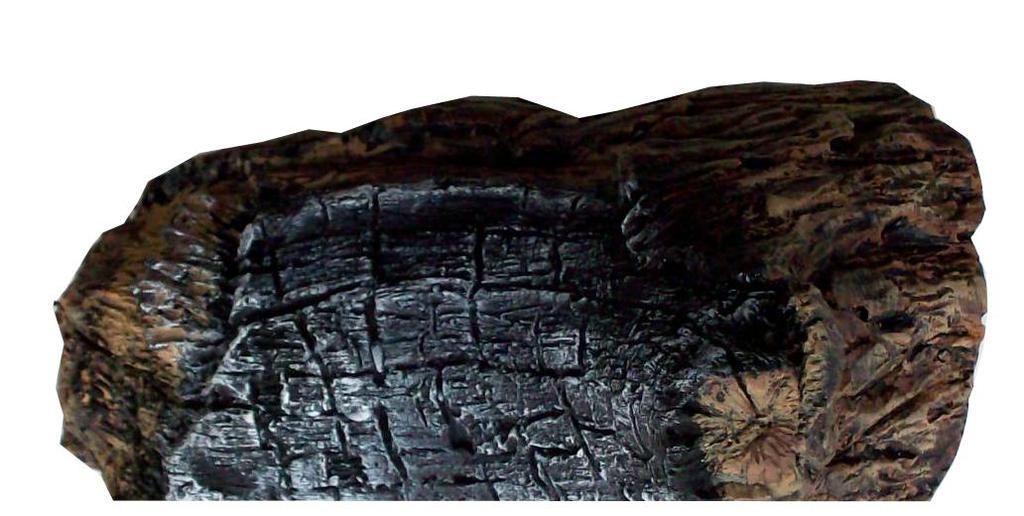
19 LOG PLACEMENT Before you begin This unit is supplied with seven (7) ceramic fiber logs. Do not handle these logs with your bare hands. Always wear gloves to prevent skin irritation from ceramic fibers. After handling the logs, wash your hands gently with soap and water to remove any traces of fibers. The positioning of the logs is critical to the safe and clean operation of this heater. Sooting and other problems may result if the logs are not properly and firmly positioned in the appliance. Never add additional logs or embellishments such as pine cones or vermiculite to the heater. Only use the logs supplied with the unit. Failure to position the parts in accordance with diagrams below or to use only parts specifically approved for this heater may result in property damage or personal injury. INSTALLING LOGS AND ROCK WOOL (EMBER MATERIAL) IN FIREBOX 1. Open front door of firebox. 2. Break up rock wool (ember material) into dime-sized pieces. Place evenly across burner surface and mesh of grate. Do not exceed 1" depth of coverage. See Figure 16 Rock Wool Figure 16 - Rock Wool Placement 3. Carefully remove seven (7) logs from wrapping. 4. Place rear log (#1) against back of firebox. See Figure 17. Figure 17 - Installing Rear Log #1 19
 Figure 19 - Installing Right Base Log #3 7. Place right center log (#4) on top pin of the right base log (#3). See Figure 20.")
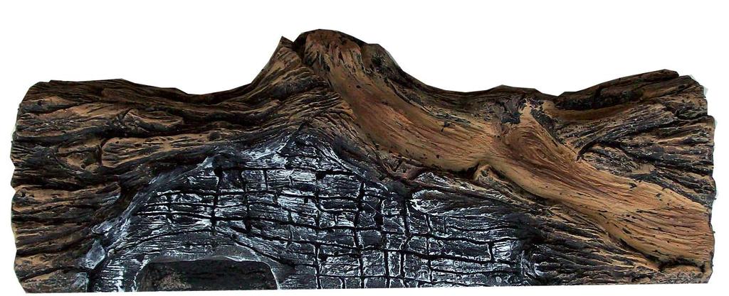
20 LOG PLACEMENT 5. Install left base log (#2). See Figure 18. Left Base Log (#2) Figure 18 - Installing Left Base Log #2 6. Place right base log (#3) to the right of rear log (#1). See Figure 19. Right Base Log (#3) Figure 19 - Installing Right Base Log #3 7. Place right center log (#4) on top pin of the right base log (#3). See Figure 20. Right Center Log (#4) Figure 20 - Installing Right Center Log #4 20
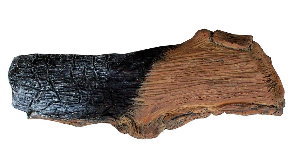
21 LOG PLACEMENT 8. Set left center log (#5) on the left base log (#2) pin. See Figure 21. Left Center Log (#5) Figure 21 - Installing Left Center Log #5 9. Place one end of center top log (#6) on rear log (#1). Line up hole in bottom of center top log (#6) with pin on rear log (#1). See Figure 22. Center Top Log (#6) Figure 22 - Installing Center Top Log #6 21
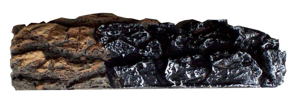
22 LOG PLACEMENT 10. Lay top right log (#7) across rear log (#1) and right center logs #4. Place the log on two (2) pins provided. See Figure 23. Top Right Log (#7) Figure 23 - Installing Top Right Log #7 11. Lightly cover space between logs and burner with small pieces of rock wool for a better burner flame and glow. 22
23 TRIM INSTALLATION ASSEMBLING TRIM 1. Lay out trim and L brackets on floor. See Figure Put trim together at 45 angles to form a corner. Insert L bracket into slots in back of trim. Tighten screws with flat head screwdriver. See Figure 25. Make sure there are no gaps at the 45 angle. Top Trim Piece L Brackets Side Trim Pieces INSTALLING TRIM 1. Slide trim over surround. See Figure Tighten the seven (7) machine screws located around the perimeter to secure the trim to the surround. Figure 24 - Aligning Trim on Floor Surround Top of Trim Screws Trim Back of Trim L Bracket Figure 25 - Installing trim on the surround 23


24 INSTALLING FACING 1. Locate the four (two upper and two lower) vertical slots in the gas insert on both sides of the glass door Locate the corresponding vertical hooks on the back of the filigree face. Place the facing assembly in front of the appliance and align the hooks with the slots. NOTICE Before installing the facing remove all fingerprints from the glass door and facing with a 50/50 vinegar and water solution. Any fingerprints left on the glass or the facing will be permanent when heater is lit Position the facing so the hooks are inserted into the slots and then allow the facing to drop down firmly inside the slots. The photograph below shows correctly engaged hook inside of the slot. Filigree Facing Safety Screen attached to the Filigree Facing Figure 27 - Installing Filigree Facing 24
25 SAFETY SCREEN REPLACEMENT : A barrier (safety screen) designed to reduce the risk of burns from the hot viewing glass is provided with this appliance and shall be installed for the protection of children and other at-risk individuals. IMPORTANT: Safety Screen must be in place when the fireplace is in operation. If the barrier becomes damaged, the barrier shall be replaced with the manufacturer's barrier for this appliance. Any safety screen, guard, or barrier removed for servicing the appliance, must be replaced prior to operating the appliance. 25
26 OPERATING INSTRUCTIONS FOR YOUR SAFETY READ BEFORE LIGHTING If you do not follow these instruction exactly, a fire or explosion may result causing property damage, personal injury or loss of life. A. This appliance is equipped with a pilot piezo ignition system. Follow these instructions exactly to light pilot. B. BEFORE OPERATING smell all around the appliance area for gas. Be sure to smell next to the floor because some gas is heavier than air and will settle on the floor. WHAT TO DO IF YOU SMELL GAS: Turn off all gas to the appliance. Open windows. Do not attempt to light any appliance. Do not touch any electric switch; do not use any phone in your building. Immediately call your gas supplier from a neighbor's phone. Follow the gas supplier's instructions. If you cannot reach your gas supplier, call the fire department. C. Use only your hand to push in, or turn the gas control knob. Never use tools. If the knob will not push in or turn by hand, don't try to repair it. Call a qualified service technician. Force or attempted repair may result in a fire or explosion. D. Do not use this appliance if any part of it has been under water. Immediately call a qualified service technician to inspect the appliance and to replace any part of the control system and any gas control that has been under water. LIGHTING PILOT FOR THE FIRST TIME INITIAL LIGHTING Purge air from the supply line as follows: Open main shutoff valve. Unscrew main pressure test point. Leave inlet test screw open until gas comes in. When gas is flowing, tighten inlet screw immediately. LEAK TESTING 1. Follow the pipe from the gas supply line connection to the gas valve. Check connection for leaks with soap and water mixture. 2. Next check for gas leaks at the burner thread inlet with soap and water mixture. 3. Check the pilot for gas leaks with soap and water mixture. Never use an open flame to check for gas leak. Continued on next page 26
27 OPERATING INSTRUCTIONS LIGHTING PILOT FOR THE FIRST TIME LEAK TESTING (continued) You may check for gas leaks with the following methods only: If using a soap and water solution to test for leaks, Soap and water solution DO NOT spray solution onto An approved leak testing spray control body. Electronic sniffer Check for gas leaks in each of the following locations: Pipe from the gas supply line connection to the gas valve Burner thread inlet Field made joints Pilot Factory made joints Each joint or connection All joints on valve and control body T NOTE: Remove any excessive pipe compound from the connections. Excessive pipe compound can set off electronic sniffers. LIGHTING PILOT The control has an interlock device that does not allow the lighting of the insert up to the moment the safety device of the flame has not interrupted the gas flow. After that period of time (when the magnet is closed), it is possible to start the lighting operation. The gas control knob is designed to be operated by hand. DO NOT use any tools during this operation. Damaged knobs may result in serious injury. 1. Depress and turn knob counterclockwise to pilot position. 2. Depress fully and hold pilot gas knob. The electronic ignitor will automatically ignite the pilot. Keep knob fully depressed for a few seconds. Release and check that pilot continues to burn. If the pilot does not stay lit, repeat steps 1 and 2. If the knob does not pop out to its original position when released, turn off gas to appliance and contact qualified service technician. Figure 29 - Pilot Position 27
28 LIGHTING BURNER OPERATING INSTRUCTIONS MAIN BURNER SWITCH The ON/OFF/REMOTE switch for the main burner can be found on the right side of insert surround. This switch allows you to turn on and to turn off the main burner without using the gas valve knob. Make sure the button is in the ON position to light the main burner. See Figure 30. LIGHTING THE BURNER Depress and turn the knob counterclockwise to the ON position. See Figure 31. It will take less than four (4) seconds for the burner to ignite. PILOT POSITION Depress and turn knob to pilot position to keep burner off while maintaining the pilot light. See Figure 32. T Figure 30 - On/Off/Remote Switch Figure 31 - On Position TO TURN OFF GAS Figure 32 - Pilot Position Depress and turn knob clockwise position. See Figure 33. to OFF Figure 33 - Off Position ADJUSTING BLOWER SPEED The internal blower helps transfer heat from heater into room. It will not turn on until heater is up to temperature (approximately 10 minutes after starting). To turn blower off, turn knob all the way counter-clockwise. One click clockwise turns blower to high speed. Turning knob clockwise from high position decreases speed of blower. See Figure 34. Figure 34 - Blower Knob 28
29 CLEANING AND MAINTENANCE Make sure the gas valve knob is in the OFF position. Wait at least five (5) minutes before starting maintenance. VENTING SYSTEM A qualified agency should examine the venting system annually. CLEANING GLASS Clean the ceramic glass periodically. Condensation will sometimes form on the glass during a cold startup. This is normal for all gas fireplaces and inserts. This condensation often attracts dust and lint to the surface of the glass. The initial paint curing of the appliance can also leave a slight film on the glass. This is a temporary problem. Let glass cool before cleaning. Do not clean glass when it is hot. Damage could occur. Your should clean the glass after the first two weeks of use. After that, you should clean the glass no more than two or three times a season. Use a mild glass cleaner to clean the door. Do not use abrasive cleaners. They will damage the glass surface. PILOT AND BURNER FLAMES Visually check pilot and burner flames periodically. See Figure 35 for typical burner flame. There is no air adjustment on the main burner. The air shutter is preset at the factory. SSee Figure 36 for typical pilot flame. CAUTION Thermocouple Thermopile Figure 35 - Typical Burner Flame FIREBOX CLEANING 1. Carefully remove log set, and embers from combustion chamber. 2. Vacuum burner compartment thoroughly. 3. Vacuum any dust off logs. 4. Remove any lint from main burner and pilot. 5. Carefully replace log set, and embers in their correct positions. See pages 19 through Replace door (if it has been removed). 7. Relight pilot. See page Turn on main burners. Figure 36 - Typical Pilot Flame Make sure that clearances to combustibles leave enough room for maintenance and service. Carefully reassemble and reseal insert properly after any cleaning or servicing. 29
30 GLASS REPLACEMENT NOTE: Use only original Woodbridge Fireplace replacement parts. CAUTION Always use gloves when handling broken glass. Make sure the glass panel edges do not touch any metal parts during thermal expansion. 1. Put on gloves. Remove frame from insert by removing three nuts, washers and springs. See Figure stud Frame spring washer nut 2. Carefully remove the door with brocken glass. See Figure Wrap new glass with tadpole gasket. See Figure Plase new glass in frame. 5. Slide door back down onto insert and fasten. See Figure Glass Frame Gasket Figure 37 - Removing Glass Door Correct installation of glass frame: Glass 3/16" Figure 38 - Replacing Glass (Inside of Frame Shown) 30
31 MAINTENANCE MAINTAINING YOUR HEATER S APPEARANCE Fingerprints or other marks left on optional gold or nickel surface may become etched in place if they are not wiped clean prior to turning stove on. Clean gold or nickel with a 50/50 vinegar and water solution and soft cloth soft cloth. NOTE: Make sure heater is cool before cleaning. Using cleaners other than a 50/50 vinegar and water solution may leave a film that becomes permanently etched into the gold or nickel. YEARLY SERVICE PROCEDURE Thermocouple Failure to inspect and maintain heater may lead to improper combustion and a Thermopile potentially dangerous situation. A qualified technician should do the following once a year. 1. Check pilot flame. Flame should touch approximately 3 /8" of the top of thermopile and touch top of thermocouple. See Figure 39. If not, contact dealer for service. 2. Turn gas control knob to OFF position to shut off gas to heater. See step To Turn Off Gas, page 28. Let heater cool for 15 minutes. Remove faceplate (see instructions included with face plate) and glass. See page Carefully remove log set. If logs are severely deteriorated, replace logs. Check logs for sooting. A small amount of soot along bottom of logs is normal. If excessive sooting is found, heater must be adjusted. Contact dealer where you bought heater. 4. Clean burner and burner ports. Inspect the following. See Figure 40: Check burner ports for cracks, warpage and corrosion. Make sure burner assembly is not warped or damaged. Check firebox and area around pilot to make sure there is no warping or damage. If any problem is found, do not use heater. Contact your dealer for service. Figure 39 - Before taking unit apart, check pilot flame. Flame should touch thermocouple and thermopile Check walls and ceiling of firebox for deterioration Check burner ports Make sure burner is not warped or damaged Figure 40 - Checking Burner Ports, Burners, Walls, and Ceiling of Unit Continued on Next Page 31
32 MAINTENANCE 5. Replace log set and rock wool per instructions on pages Replace glass. Make sure gasket along perimeter of glass contacts face of firebox and forms an airtight seal. Realign if airtight seal is not formed. Replace glass and glass frame if damaged. 6. Inspect area behind access door. Clean if necessary. Check gas control valve and all gas lines. If damaged, do not use heater. Contact your dealer. 7. Start pilot and turn on main burner. Flames should be orange/yellow and not touch top of firebox. If pilot or main burner do not burn correctly, contact your dealer for service. Monitor blower operation. 32
33 BLOWER BLOWER FAN ASSEMBLY DIAGRAMS NOTE: Unplug power cord before servicing. The blower is attached to the insert bottom and back with Velcro. To remove blower for servicing, pull away from Velcro and disconnect wires. Spade Terminals Velcro Strips Switch Bracket Speed Control Control Shaft Blower Plug-In Green Ground Wire Screw Exhaust Port Control Knob Locknut Duplex Outlet (Located underneath firebox floor against lower right outside wall, as shown on page 5) CAUTION Label all wires prior to disconnection when servicing controls. Wiring errors can cause improper and dangerous operation. Verify proper operation after servicing. Figure 41 - Fan wire assembly diagram Electrical Grounding Instructions The appliance is equipped with a three-prong (grounding) plug for your protection against shock hazzard and should be plugged into a properly grounded three-prong receptacle. Do not cut or remove the grounding prong from this plug. 33
34 REPLACEMENT PARTS Continued on Next Page 34


35 REPLACEMENT PARTS Continued on Next Page 35

36 REPLACEMENT PARTS Any parts that need to be replaced must be ordered from the manufacturer. Do not use substitute materials.
37 REPLACEMENT PARTS REPLACEMENT PARTS ARE AVAILABLE THROUGH YOUR RETAILER DVI1000 Item Description QTY Natural Propane 1 SIT Pilot Assembly 1 C C Ignition Switch w/cable 1 C C Insert Top 1 E100012P E100012P 4 Vent Manifold 1 W100100P W100100P 5 Burner Weldment 1 W500026P W500026P 6 Log Support 1 E100020P E100020P 7 Burner Front Cover 1 E100017P E100017P 8 Burner Tube 1 C C Optional Wall Switch 1 A10000 A Left Brick Liner Panel 1 E100018L E100018L 11 Rear Brick Liner Panel 1 E E Right Brick Liner Panel 1 E100018R E100018R 13 Main Gas Valve 1 C C Glass Frame 1 W500027P W500027P 15 Glass Frame Gasket 1 I I Ceramic Glass 1 G G Ventury 1 C C100008A 18 Flexhose w/shutoff Valve 1 C C Thermostat Blower 1 A A Orifice 1 E E Failure to position the parts in accordance with these diagrams or failure to use only parts specifically approved with this appliance may result in property damage or personal injury. Logs 21 Rear Log 1 E E Left Base Log 1 E E Right Base Log 1 E E Left Center Log 1 E E Right Center Log 1 E E Center Top Log 1 E E Top Right Log 1 E E Facing 28 Filigree Face Assembly 1 E E with Safety screen This list contains replaceable parts used in your firebox. All replacement parts should be ordered from your installer or from Woodbridge Fireplace Inc. at or on-line at 37
38 TROUBLESHOOTING Turn appliance OFF and allow to cool before servicing. Only a qualified service person should service and repair the heater. Note: All troubleshooting items are listed in order of operation. OBSERVED PROBLEM Spark ignitor will not light the pilot after repeated pressing of spark ignitor. Pilot will not stay lit. Burner will not light when valve and burner switch are both on. Glass fogs up Blue flames Sooting POSSIBLE CAUSE 1. Battery needs replacing 2. Defective ignitor 3. Misaligned spark electrode 1. Defective thermocouple. Loose thermocouple 2. Air in gas line 3. No gas 1. Defective switch 2. Defective thermopile 3. Thermostat set too low/defective 1. Normal condition 1. Normal during start up 1. Flame impingement REMEDY 1. Replace battery 2. Check connections to ignitor. Replace ignitor if ignitor connections are good, but there is no spark. 3. Check for spark arcing from the electrode to pilot. Adjust and retighten. 1. Check for proper connection of thermocouple to rear of valve. 2. Bleed line. Contact dealer 3. Check shutoff valve and gas supply (LPG tank) 1. Check switch connections. Jump wires at switch. 2. Check connections to valve. Contact dealer. 3. Turn up thermostat to start unit. Check thermostat connections. 1. Allow appliance to warm up. Glass will clear. Additives in the gas may dirty glass. Clean glass when cool. 1. Flames will yellow as appliance heats up. 1. Check log position. Open shutters to increase primary air. 38
Woodbridge Fireplace Inc.
 Woodbridge Fireplace Inc. Report # 0401GN010S DIRECT VENT GAS INSERT MODEL DVI 751 INSTALLATION AND OPERATING INSTRUCTIONS WARNING: FIRE OR EXPLOSION HAZARD Failure to follow safety warnings exactly could
DIRECT VENT GAS INSERT
 DIRECT VENT GAS INSERT INSTALLATION AND OPERATING INSTRUCTIONS MODELS: IDV490NVC, IDV490PVC, IDV380NVC, AND IDV380PVC S IF THE INFORMATION IN THESE INSTRUCTIONS ARE NOT FOLLOWED EXACTLY, A FIRE OR EXPLOSION
DIRECT VENT GAS INSERT
 DIRECT VENT GAS INSERT INSTALLATION AND OPERATING INSTRUCTIONS MODELS: 490IDVNV, 490IDVPV, 380IDVNV, and 380IDVPV WARNINGS If the information in these instructions are not followed exactly, a fire or explosion
ILDV Series Direct Vent Gas Fireplace Insert
 ILDV Series Direct Vent Gas Fireplace Insert Models: 20iLDVNV & 20iLDVPV 30ILDVNV & 30ILDVPV 40ILDVNV & 40ILDVPV If the information in these instructions is not followed exactly, a fire or explosion may
DANGER HOT GLASS WILL CAUSE BURNS. DANGER. ILDV Series Direct Vent Gas Fireplace Insert Installation and Operating Instructions
 ILDV Series Direct Vent Gas Fireplace Insert Installation and Operating Instructions Models: 30ILDVNV, 30ILDVPV : FIRE OR EXPLOSION HAZARD Failure to follow safety warnings exactly could result in serious
IDV Series Direct Vent Gas Fireplace Insert
 IDV Series Direct Vent Gas Fireplace Insert Models: 380IDVNVC & 380IDVPVC 490IDVNVC & 490IDVPVC If the information in these instructions is not followed exactly, a fire or explosion may result causing
PRE-PLANNING GUIDE for the Linear Burner System
 PRE-PLANNING GUIDE for the Linear Burner System GAS PRESSURE SPARK products are engineered, safety tested and certified to function properly within a specific gas supply pressure range. It is CRITICALLY
FIREPLACE INSTALLATION
 CHECK GAS TYPE Use proper gas type for the fireplace unit you are installing. If you have conflicting gas types, do not install fireplace. See retailer where you purchased the fireplace for proper fireplace
CAUTION FOR YOUR SAFETY
 VENT-FREE GAS FIREBOX Model # PC32VFC & PC36VFC CAUTION FOR YOUR SAFETY WARNING: IF THE INFORMATION IN THIS MANUAL IS NOT FOLLOWED EXACTLY, A FIRE MAY RESULT CAUSING PROPERTY DAMAGE, PERSONAL INJURY, OR
OPERATING INSTRUCTIONS AND OWNER S MANUAL
 OPERATING INSTRUCTIONS AND OWNER S MANUAL MR. HEATER READ INSTRUCTIONS CAREFULLY: Read and follow all instructions. Place instructions in a safe place for future reference. Do not allow anyone who has
Using it in an enclosed space can kill you.
 38 X 56 GAS FIRE PIT - OWNER S MANUAL Carlisle Chat Fire Table Base Model # 00GBC7 (6877B) Fits 6877A Carlisle Chat Fire Table Top For Propane and *Natural Gas (*See Page 7) Certified to CSA International
LEXINGTON FORGE DIRECT VENT GAS STOVE INSTALLATION AND OPERATING INSTRUCTIONS
 LEXINGTON FORGE DIRECT VENT GAS STOVE INSTALLATION AND OPERATING INSTRUCTIONS MODEL: STRATFORD SS38DV S IF THE INFORMATION IN THESE INSTRUCTIONS ARE NOT FOLLOWED EXACTLY, A FIRE OR EXPLOSION MAY RESULT
GFP28MLP AND GFP28TLP
 UNVENTED (VENT-FREE) PROPANE/LP GAS FIREPLACE This appliance may be installed in an aftermarket* manufactured (mobile) home, where not prohibited by state or local codes. * Aftermarket: Completion of sale,
SIERRA RADIANT HEAT MAJESTIC OAK VENTED GAS LOG KIT INSTALLATION AND OPERATING INSTRUCTIONS
 SIERRA RADIANT HEAT MAJESTIC OAK VENTED GAS LOG KIT INSTALLATION AND OPERATING INSTRUCTIONS WARNING: If the information in this manual is not followed exactly, a fire or explosion may result causing property
Owner s Guide Installation & Operation
 Owner s Guide Installation & Operation Char Broiler HCH Series Hestan Commercial Corporation 3375 E. La Palma Ave Anaheim, CA 92806 (888) 905-7463 RETAIN THIS MANUAL FOR FUTURE REFERENCE P/N 002134 REV
Models #CSK-31 #CSK-31-RF. CHASKA Direct Vent Gas Fireplace Insert INSTALLATION & OPERATING MANUAL
 WARNING: If the information in these instructions are not followed exactly, a fire or explosion may result causing property damage, personal injury or loss of life. Models #CSK-31 #CSK-31-RF CHASKA Direct
Installer: Leave this manual with the appliance. Consumer: Retain this manual for future reference.
 Installer: Leave this manual with the appliance. Consumer: Retain this manual for future reference. Operating Instructions and Owner s Manual READ INSTRUCTIONS CAREFULLY: Read and follow all instructions.
PAULIN PRODUCTS INDOOR HEATER
 PAULIN PRODUCTS INDOOR HEATER OWNER S MANUAL AND OPERATING INSTRUCTIONS May be used with a disposable 1 lb. propane cylinder: - for emergency indoor home heating - for indoor use in commercial enclosures,
Comfort UNVENTED (VENT-FREE) GAS LOG HEATER OWNER S OPERATION AND INSTALLATION MANUAL
 GAS LOG HEATER OWNER S OPERATION AND INSTALLATION MANUAL") Comfort by Flame TM FMI PRODUCTS, LLC UNVENTED (VENT-FREE) GAS LOG HEATER OWNER S OPERATION AND INSTALLATION MANUAL PFS US Remote-Ready Models CRB3624(N,P)RA Thermostatically-Controlled Models CSG3924(N,P)TB
Comfort by Flame TM FMI PRODUCTS, LLC UNVENTED (VENT-FREE) GAS LOG HEATER OWNER S OPERATION AND INSTALLATION MANUAL PFS US Remote-Ready Models CRB3624(N,P)RA Thermostatically-Controlled Models CSG3924(N,P)TB
MODELS LFP4218/LFP6018 TOP VENT GAS FIREPLACE
 MODELS LFP4218/LFP6018 TOP VENT GAS FIREPLACE PFS APPROVED FOR NATURAL GAS OR PROPANE GAS Z21.50-2014 If your plans do not allow for the venting system as outlined previously in the installing chimney/vent
Legend VENTED GAS FIREPLACE HEATERS
 MODEL 937XN FOR USE WITH NATURAL GAS Legend MODEL 937XP FOR USE WITH PROPANE VENTED GAS FIREPLACE HEATERS WARNING: If the information in this manual is not followed exactly, a fire or explosion may result
Models #CSK-335 #CSK-335-RF. CHASKA - XL Direct Vent Gas Fireplace Insert INSTALLATION & OPERATING MANUAL
 WARNING: If the information in these instructions are not followed exactly, a fire or explosion may result causing property damage, personal injury or loss of life. Models #CSK-335 #CSK-335-RF CHASKA -
UNVENTED (VENT-FREE) BLUE FLAME GAS HEATER SAFETY INFORMATION AND INSTALLATION MANUAL
 BLUE FLAME GAS HEATER SAFETY INFORMATION AND INSTALLATION MANUAL") UNVENTED (VENT-FREE) BLUE FLAME GAS HEATER SAFETY INFORMATION AND INSTALLATION MANUAL MANUAL 10,000 BTU - 10542 AND 10543 THERMOSTAT 10,000 BTU - 10544 AND 10545 THERMOSTAT 20,000 BTU - 10546 AND 10547
UNVENTED (VENT-FREE) BLUE FLAME GAS HEATER SAFETY INFORMATION AND INSTALLATION MANUAL MANUAL 10,000 BTU - 10542 AND 10543 THERMOSTAT 10,000 BTU - 10544 AND 10545 THERMOSTAT 20,000 BTU - 10546 AND 10547
United States Stove Company
 United States Stove Company Vent-Free Gas Fireplace Model: 2020L Model: 2020N OWNER'S OPERATION AND INSTALLATION MANUAL This firebox may be installed in an aftermarket* manufactured (mobile) home, where
UNVENTED (VENT-FREE) GAS LOG HEATER
 GAS LOG HEATER") LO UNVENTED (VENT-FREE) GAS LOG HEATER TM OWNER S OPERATION AND INSTALLATION MANUAL ("A" Models) 18", 24", and 30" Remote-Ready ( C Models) 18", 24", and 30" Variable Manually-Controlled PILOT OFF HI (
LO UNVENTED (VENT-FREE) GAS LOG HEATER TM OWNER S OPERATION AND INSTALLATION MANUAL ("A" Models) 18", 24", and 30" Remote-Ready ( C Models) 18", 24", and 30" Variable Manually-Controlled PILOT OFF HI (
UNVENTED (VENT-FREE) PROPANE/LP GAS LOG HEATER
 PROPANE/LP GAS LOG HEATER") UNVENTED (VENT-FREE) PROPANE/LP GAS LOG HEATER OWNER S OPERATION AND INSTALLATION MANUAL FLAME-MAX Vintage Oak Log Design FLAME-MAX Golden Oak Log Design FLAME-MAX Birch Log Design 18" and 24" Variable
UNVENTED (VENT-FREE) PROPANE/LP GAS LOG HEATER OWNER S OPERATION AND INSTALLATION MANUAL FLAME-MAX Vintage Oak Log Design FLAME-MAX Golden Oak Log Design FLAME-MAX Birch Log Design 18" and 24" Variable
INSTALLER: Leave this manual with the appliance. CONSUMER: Retain this manual for future reference.
 UNVENTED (VENT-FREE) GAS LOG HEATER OWNER S OPERATION AND INSTALLATION MANUAL Models EZ18N, EZ18P, EZ24N and EZ24P 18" and 24" Variable Manually-Controlled Design-Certified As Vented Decorative Appliances
UNVENTED (VENT-FREE) PROPANE GAS FIREPLACE
 PROPANE GAS FIREPLACE") DESA INTERNATIONAL UNVENTED (VENT-FREE) PROPANE GAS FIREPLACE This appliance may be installed in an aftermarket* manufactured (mobile) home, where not prohibited by state or local codes. * Aftermarket:
DESA INTERNATIONAL UNVENTED (VENT-FREE) PROPANE GAS FIREPLACE This appliance may be installed in an aftermarket* manufactured (mobile) home, where not prohibited by state or local codes. * Aftermarket:
OUTDOOR FIRE CUBE with pilot safety system. Model FBB-N(P)-S OWNER S OPERATION AND INSTALLATION MANUAL
-S OWNER S OPERATION AND INSTALLATION MANUAL") S P A R K M O D E R N F I R E S OUTDOOR FIRE CUBE with pilot safety system Model FBB-N(P)-S OWNER S OPERATION AND INSTALLATION MANUAL We recommend that our products be installed and serviced by professionals
S P A R K M O D E R N F I R E S OUTDOOR FIRE CUBE with pilot safety system Model FBB-N(P)-S OWNER S OPERATION AND INSTALLATION MANUAL We recommend that our products be installed and serviced by professionals
UNVENTED (VENT-FREE) GAS LOG HEATER OWNER S OPERATION AND INSTALLATION MANUAL
 GAS LOG HEATER OWNER S OPERATION AND INSTALLATION MANUAL") UNVENTED (VENT-FREE) GAS LOG HEATER OWNER S OPERATION AND INSTALLATION MANUAL PFS US VARIABLE MANUALLY CONTROLLED BURNER SYSTEM MODELS EWPO2430NM AND EWPO2430PM, FOR USE WITH EWPO18R, EWPO24R AND EWPO30R,
UNVENTED (VENT-FREE) GAS LOG HEATER OWNER S OPERATION AND INSTALLATION MANUAL PFS US VARIABLE MANUALLY CONTROLLED BURNER SYSTEM MODELS EWPO2430NM AND EWPO2430PM, FOR USE WITH EWPO18R, EWPO24R AND EWPO30R,
MODEL 329 MAY BE INSTALLED IN A SOLID FUEL BURNING FIREPLACE, AS A FREESTANDING FIREPLACE OR WITH AN OPTIONAL WOODEN SURROUND.
 MODEL 329 MAY BE INSTALLED IN A SOLID FUEL BURNING FIREPLACE, AS A FREESTANDING FIREPLACE OR WITH AN OPTIONAL WOODEN SURROUND. VENT-FREE WARNING: If the information in this manual is not followed exactly,
UNVENTED (VENT-FREE) GAS LOG HEATER OWNER S OPERATION AND INSTALLATION MANUAL
 GAS LOG HEATER OWNER S OPERATION AND INSTALLATION MANUAL") LO HI OFF Pilot UNVENTED (VENT-FREE) GAS LOG HEATER OWNER S OPERATION AND INSTALLATION MANUAL Remote-Ready and Variable Manually-Controlled Models Also Design-Certified As Vented Decorative Appliances
LO HI OFF Pilot UNVENTED (VENT-FREE) GAS LOG HEATER OWNER S OPERATION AND INSTALLATION MANUAL Remote-Ready and Variable Manually-Controlled Models Also Design-Certified As Vented Decorative Appliances
Installation/Operating Instructions
 Installation/Operating Instructions Models: 4072-180 24 NG 4072-182 30 NG Outdoor Hearth Kit DO NOT DISCARD INSTALLER: Leave this manual with party responsible for use and operation. OWNER: Retain this
INSTALLER: Leave this manual with the appliance. CONSUMER: Retain this manual for future reference.
 VENT-FREE GAS FIREPLACE INSERT OWNER S OPERATION AND INSTALLATION MANUAL MODEL FDF150T PFS US WARNING: If the information in this manual is not followed exactly, a fire or explosion may result causing
Owner s Guide Installation & Operation
 Owner s Guide Installation & Operation Hot Top HHT Series Hestan Commercial Corporation 3375 E. La Palma Ave Anaheim, CA 92806 (888) 905-7463 RETAIN THIS MANUAL FOR FUTURE REFERENCE P/N 002130 REV 1 IMPORTANT
ROYAL ENGLISH OAK UNVENTED (VENT-FREE) GAS LOG HEATER OWNER S OPERATION AND INSTALLATION MANUAL
 GAS LOG HEATER OWNER S OPERATION AND INSTALLATION MANUAL") ROYAL ENGLISH OAK UNVENTED (VENT-FREE) GAS LOG HEATER OWNER S OPERATION AND INSTALLATION MANUAL Patent Pending 24" Thermostatically-Controlled Models CLD3924PTC and CLD3924NTC WARNING: If the information
ROYAL ENGLISH OAK UNVENTED (VENT-FREE) GAS LOG HEATER OWNER S OPERATION AND INSTALLATION MANUAL Patent Pending 24" Thermostatically-Controlled Models CLD3924PTC and CLD3924NTC WARNING: If the information
CAST IRON STOVE AND B-VENT (FREESTANDING FIREPLACE HEATER) BURNER SYSTEM
 BURNER SYSTEM") CAST IRON STOVE AND B-VENT (FREESTANDING FIREPLACE HEATER) BURNER SYSTEM OWNER S OPERATION AND INSTALLATION MANUAL NATURAL GAS BURNER SYSTEM MODEL MSTBVN PROPANE/LP GAS BURNER SYSTEM MODEL MSTBVP REMOTE
CAST IRON STOVE AND B-VENT (FREESTANDING FIREPLACE HEATER) BURNER SYSTEM OWNER S OPERATION AND INSTALLATION MANUAL NATURAL GAS BURNER SYSTEM MODEL MSTBVN PROPANE/LP GAS BURNER SYSTEM MODEL MSTBVP REMOTE
INSTALLATION INSTRUCTIONS AND OWNER'S MANUAL
 INSTALLATION INSTRUCTIONS AND OWNER'S MANUAL RAVENWOOD LOG SET FOR UNVENTED GAS LOG HEATER OR VENTED DECORATIVE APPLIANCE STANDARD MODELS ALS18RV-1 ALS24RV-1 ALS30RV-1 GAS-FIRED SELECT MODELS ALS24RVS-1
PFS. Installation and Operation Instructions Unvented (Vent-Free) Gas Fireplace Insert. Models VCI3032ZMN VCI3032ZMP
 Gas Fireplace Insert. Models VCI3032ZMN VCI3032ZMP") Installation and Operation Instructions Unvented (Vent-Free) Gas Fireplace Insert P/N 127119-01 Rev B 12/2016 P127119 01 PFS US REPORT NO. F09-121 Models VCI3032ZMN VCI3032ZMP INSTALLER: Leave this manual
Installation and Operation Instructions Unvented (Vent-Free) Gas Fireplace Insert P/N 127119-01 Rev B 12/2016 P127119 01 PFS US REPORT NO. F09-121 Models VCI3032ZMN VCI3032ZMP INSTALLER: Leave this manual
UNVENTED (VENT-FREE) GAS LOG HEATER OWNER S OPERATION AND INSTALLATION MANUAL
 GAS LOG HEATER OWNER S OPERATION AND INSTALLATION MANUAL") LO PILOT OFF HI UNVENTED (VENT-FREE) GAS LOG HEATER OWNER S OPERATION AND INSTALLATION MANUAL ("R" Models) 18", 24", 30" and 36" Remote-Ready ( V Models) 18", 24", 30" and 36" Variable Manually- Controlled
LO PILOT OFF HI UNVENTED (VENT-FREE) GAS LOG HEATER OWNER S OPERATION AND INSTALLATION MANUAL ("R" Models) 18", 24", 30" and 36" Remote-Ready ( V Models) 18", 24", 30" and 36" Variable Manually- Controlled
Heat-N-Glo Fireplace. Installers Guide. Model: AT-GRAND
 Heat-N-Glo Fireplace Model: AT-GRAND Installers Guide Patents Pending Underwriters Laboratories Listed WARNING: IF THE INFORMATION IN THESE INSTRUCTIONS IS NOT FOLLOWED EXACTLY, A FIRE OR EXPLOSION MAY
DESA INTERNATIONAL UNVENTED (VENT-FREE) PROPANE GAS LOG HEATER
 PROPANE GAS LOG HEATER") DESA INTERNATIONAL UNVENTED (VENT-FREE) PROPANE GAS LOG HEATER Manually Control Models Also Designed Certified as Vented Decorative Appliance) This appliance may be installed in an aftermarket* manufactured
DESA INTERNATIONAL UNVENTED (VENT-FREE) PROPANE GAS LOG HEATER Manually Control Models Also Designed Certified as Vented Decorative Appliance) This appliance may be installed in an aftermarket* manufactured
VENTED DECORATIVE GAS LOG HEATER OWNER S OPERATION AND INSTALLATION MANUAL MODELS BQMV18N, BQMV18P, BQMV24N AND BQMV24P
 VENTED DECORATIVE GAS LOG HEATER OWNER S OPERATION AND INSTALLATION MANUAL MODELS BQMV18N, BQMV18P, BQMV24N AND BQMV24P WARNING: If the information in this manual is not followed exactly, a fire or explosion
INSTALLER: Leave this manual with the appliance. CONSUMER: Retain this manual for future reference.
 UNVENTED (VENT-FREE) GAS LOG HEATER OWNER S OPERATION AND INSTALLATION MANUAL LO HI PILOT OFF Patent Pending Variable Manually- Controlled Models HDVF3018P AND HDVF3018N Also Design-Certified As Vented
VENT-FREE PROPANE GAS HEATER
 VENT-FREE PROPANE GAS HEATER OWNER S OPERATION AND INSTALLATION MANUAL Models: VP2000BA, VP2000BTA, and VP2800BTA WARNING: If the information in this manual is not followed exactly, a fire or explosion
Clean Face Direct Vent Fireplace Insert Models: 40ICFDVLNTSC, 40ICFDVLPTSC, 40ICFDVCNTSC
 Installation and Operating Instructions WARNING If the information in these instructions is not followed exactly, a fire or explosion may result causing property damage, personal injury or loss of life.
CYLINDER NOT INCLUDED
 OPERATING INSTRUCTIONS AND OWNER S MANUAL Model # HS125NG / MH125LP / HS125LP READ INSTRUCTIONS CAREFULLY: Read and follow all instructions. Place instructions in a safe place for future reference. Do
VENT-FREE PROPANE/LP GAS COMPACT CLASSIC HEARTH FIREPLACE OWNER S OPERATION AND INSTALLATION MANUAL
 VENT-FREE PROPANE/LP GAS COMPACT CLASSIC HEARTH FIREPLACE OWNER S OPERATION AND INSTALLATION MANUAL 14,000 to 26,000 Btu/Hr with Thermostat Shown with Optional Cabinet Mantel/Hearth Base Accessory VMH26TP
STONE RIVER. The White Mountain Log Collection: LSU24SF-2 Shown
 INSTALLATION Instructions AND Owner's Manual The White Mountain Log Collection: STONE RIVER Log Set for vented and UNVENTED MULTI-SIDED GAS LOG HEATER MODELS LSU18SF-2 LSU24SF-2 LSU30SF-2 LSU24SF-2 Shown
MODEL 34 MAY BE INSTALLED IN A SOLID FUEL BURNING FIREPLACE, AS A ZERO CLEARANCE FIREPLACE OR WITH AN OPTIONAL SURROUND.
 MODEL 34 MAY BE INSTALLED IN A SOLID FUEL BURNING FIREPLACE, AS A ZERO CLEARANCE FIREPLACE OR WITH AN OPTIONAL SURROUND. WARNING: If the information in this manual is not followed exactly, a fire or explosion
Infrared Cabinet Heater Product Manual MODEL: RC9200IT
 Infrared Cabinet Heater Product Manual MODEL: RC9200IT CAUTION - FOR YOUR SAFETY Reecon North America, L.L.C. 1090 Freeport Road 2 nd Floor Pittsburgh, PA 15238 The installer should leave the instructions
VENTED DECORATIVE GAS LOG HEATER OWNER S OPERATION AND INSTALLATION MANUAL MPF24VNA, MPF24VPA, MPF18VNA AND MPF18VPA
 VENTED DECORATIVE GAS LOG HEATER OWNER S OPERATION AND INSTALLATION MANUAL MPF24VNA, MPF24VPA, MPF18VNA AND MPF18VPA WARNING: If the information in this manual is not followed exactly, a fire or explosion
INSTALLER: Leave this manual with the appliance. CONSUMER: Retain this manual for future reference.
 UNVENTED (VENT-FREE) GAS LOG HEATER OWNER S OPERATION AND INSTALLATION MANUAL Remote-Ready Models VUL18/24/30/36(N,P)R Thermostatically-Controlled Models VUL18/24/30/36(N,P)T Remote-Ready Models Also Design-Certified
UNVENTED (VENT-FREE) NATURAL GAS FIREPLACE OWNER S OPERATION AND INSTALLATION MANUAL
 NATURAL GAS FIREPLACE OWNER S OPERATION AND INSTALLATION MANUAL") UNVENTED (VENT-FREE) NATURAL GAS FIREPLACE OWNER S OPERATION AND INSTALLATION MANUAL Shown with optional cabinet mantel and hearth base accessories. WARNING: If the information in this manual is not followed
UNVENTED (VENT-FREE) NATURAL GAS FIREPLACE OWNER S OPERATION AND INSTALLATION MANUAL Shown with optional cabinet mantel and hearth base accessories. WARNING: If the information in this manual is not followed
WARNING: This appliance is equipped for Natural and Propane gas. Field conversion is not permitted other than between natural or propane gases.
 VENT-FREE GAS WALL HEATER OWNER S OPERATION AND INSTALLATION MANUAL BLUE FLAME MODELS FDT10BF, FDT20BF & FDT30BF FDT30BF Shown WARNING: If the information in this manual is not followed exactly, a fire
PFS VENT-FREE GAS SYSTEM OWNER'S OPERATION AND INSTALLATION MANUAL
 VENT-FREE GAS SYSTEM OWNER'S OPERATION AND INSTALLATION MANUAL MODELS FDF400T-ZC SERIES PFS US WARNING: If the information in this manual is not followed exactly, a fire or explosion may result causing
LEXINGTON FORGE DIRECT VENT GAS STOVE INSTALLATION AND OPERATING INSTRUCTIONS
 OFF ON LEXINGTON FORGE DIRECT VENT GAS STOVE INSTALLATION AND OPERATING INSTRUCTIONS MODELS: CSDV20SNV CSDV30SNV CSDV40SNV CSDV20DNV CSDV30DNV CSDV40DNV CSDV20SLP CSDV30SLP CSDV40SLP CSDV20DLP CSDV30DLP
ICFDV Series Direct Vent Gas Fireplace Insert
 ICFDV Series Direct Vent Gas Fireplace Insert Models: ICFDV30LNTSC, ICFDV30CNTSC WARNING If the information in these instructions is not followed exactly, a fire or explosion may result causing property
OPERATING INSTRUCTIONS AND OWNER S MANUAL
 MR HEATER STARTING SERIAL #: MHC1510000001 BASECAMP STARTING SERIAL #: MHC151100000001 OPERATING INSTRUCTIONS AND OWNER S MANUAL MODEL MR. HEATER MH4B READ INSTRUCTIONS CAREFULLY: Read and follow all instructions.
OPERATING INSTRUCTIONS AND OWNER S MANUAL
 Serial Numbers 734000000001000-7340000000169215 OPERATING INSTRUCTIONS AND OWNER S MANUAL Model # MH9B READ INSTRUCTIONS CAREFULLY: Read and follow all instructions. Place instructions in a safe place
UNVENTED (VENT-FREE) GAS FIREPLACE INSERT OWNER S OPERATION AND INSTALLATION MANUAL For more information, visit
 GAS FIREPLACE INSERT OWNER S OPERATION AND INSTALLATION MANUAL For more information, visit") UNVENTED (VENT-FREE) GAS FIREPLACE INSERT OWNER S OPERATION AND INSTALLATION MANUAL VI33NR VI33PR REMOTE READY GAS FIREPLACE INSERT Shown with GS38 Surround Kit and G8010 Brick Liner Accessories WARNING:
UNVENTED (VENT-FREE) GAS FIREPLACE INSERT OWNER S OPERATION AND INSTALLATION MANUAL VI33NR VI33PR REMOTE READY GAS FIREPLACE INSERT Shown with GS38 Surround Kit and G8010 Brick Liner Accessories WARNING:
UNVENTED (VENT-FREE) PROPANE/LP GAS FIREPLACE
 PROPANE/LP GAS FIREPLACE") DESA INTERNATIONAL UNVENTED (VENT-FREE) PROPANE/LP GAS FIREPLACE This appliance may be installed in an aftermarket* manufactured (mobile) home, where not prohibited by state or local codes. * Aftermarket:
DESA INTERNATIONAL UNVENTED (VENT-FREE) PROPANE/LP GAS FIREPLACE This appliance may be installed in an aftermarket* manufactured (mobile) home, where not prohibited by state or local codes. * Aftermarket:
GAS -FIRED VENTED ROOM HEATERS MODEL 61TV
 GAS -FIRED VENTED ROOM HEATERS MODEL 61TV INSTALLATION MANUAL NEW BUCK CORPORATION WARNING: Improper installation, adjustment, alteration,service or maintenance can cause injury or property damage. Refer
MODELS PCS100T AND PCS150T PFS
 VENT-FREE GAS FIREPLACE INSERT OWNER S OPERATION AND INSTALLATION MANUAL MODELS PCS100T AND PCS150T PFS US WARNING: If the information in this manual is not followed exactly, a fire or explosion may result
UNVENTED (VENT-FREE) GAS MINI COMPACT FIREPLACE OWNER S OPERATION AND INSTALLATION MANUAL
 GAS MINI COMPACT FIREPLACE OWNER S OPERATION AND INSTALLATION MANUAL") UNVENTED (VENT-FREE) GAS MINI COMPACT FIREPLACE OWNER S OPERATION AND INSTALLATION MANUAL Shown with Optional Cabinet Mantel/Hearth Base Accessory MANUAL MODELS CGMFN AND CGMFP REMOTE-READY MODELS VGMRN
UNVENTED (VENT-FREE) GAS MINI COMPACT FIREPLACE OWNER S OPERATION AND INSTALLATION MANUAL Shown with Optional Cabinet Mantel/Hearth Base Accessory MANUAL MODELS CGMFN AND CGMFP REMOTE-READY MODELS VGMRN
UNVENTED (VENT-FREE) GAS LOG HEATER OWNER S OPERATION AND INSTALLATION MANUAL
 GAS LOG HEATER OWNER S OPERATION AND INSTALLATION MANUAL") UNVENTED (VENT-FREE) GAS LOG HEATER OWNER S OPERATION AND INSTALLATION MANUAL PFS US REMOTE CONTROL READY BURNER SYSTEM MODELS EWPO2430NV AND EWPO2430PV FOR USE WITH EWPO18R, EWPO24R, AND EWPO30R LOG SETS
UNVENTED (VENT-FREE) GAS LOG HEATER OWNER S OPERATION AND INSTALLATION MANUAL PFS US REMOTE CONTROL READY BURNER SYSTEM MODELS EWPO2430NV AND EWPO2430PV FOR USE WITH EWPO18R, EWPO24R, AND EWPO30R LOG SETS
USERS INSTALLATION OPERATION and MAINTENANCE MANUAL. Installer: Please leave this manual with the appliance owner for future reference
 Optima 34 34-DVI34N For Serial Number 42164 and up Gas Fired Vented Room Heater (Direct Vent) For use with Natural Gas or Propane* WARNING: If the information in this manual is not followed exactly, fire
UNVENTED (VENT-FREE) GAS FIREPLACE INSERT OWNER S OPERATION AND INSTALLATION MANUAL VI33NRB AND VI33PRB REMOTE READY GAS FIREPLACE INSERT
 GAS FIREPLACE INSERT OWNER S OPERATION AND INSTALLATION MANUAL VI33NRB AND VI33PRB REMOTE READY GAS FIREPLACE INSERT") Vantage Hearth TM by FMI PRODUCTS, LLC UNVENTED (VENT-FREE) GAS FIREPLACE INSERT OWNER S OPERATION AND INSTALLATION MANUAL PFS US Shown with GB38 Surround Kit and Brick Liner Accessory VI33NRB AND VI33PRB
Vantage Hearth TM by FMI PRODUCTS, LLC UNVENTED (VENT-FREE) GAS FIREPLACE INSERT OWNER S OPERATION AND INSTALLATION MANUAL PFS US Shown with GB38 Surround Kit and Brick Liner Accessory VI33NRB AND VI33PRB
PFS. INSTALLER: Leave this manual with the appliance. CONSUMER: Retain this manual for future reference.
 CAST IRON STOVE AND B-VENT (FREESTANDING FIREPLACE HEATER) BURNER SYSTEM OWNER S OPERATION AND INSTALLATION MANUAL NATURAL GAS BURNER SYSTEM SBVBND PROPANE/LP GAS BURNER SYSTEM SBVBPD, REMOTE READY IMPORTANT:
MOUNTAIN OAK, PREMIUM AGED SPLIT OAK, AND SMOKY MOUNTAIN OAK UNVENTED (VENT-FREE) NATURAL GAS LOG HEATERS
 NATURAL GAS LOG HEATERS") MOUNTAIN OAK, PREMIUM AGED SPLIT OAK, AND SMOKY MOUNTAIN OAK UNVENTED (VENT-FREE) NATURAL GAS LOG HEATERS VARIABLE MANUALLY-CONTROLLED MODELS ALSO DESIGN-CERTIFIED AS VENTED DECORATIVE APPLIANCES OWNER
MOUNTAIN OAK, PREMIUM AGED SPLIT OAK, AND SMOKY MOUNTAIN OAK UNVENTED (VENT-FREE) NATURAL GAS LOG HEATERS VARIABLE MANUALLY-CONTROLLED MODELS ALSO DESIGN-CERTIFIED AS VENTED DECORATIVE APPLIANCES OWNER
INSTALLATION INSTRUCTIONS AND OWNER S MANUAL
 INSTALLATION INSTRUCTIONS AND OWNER S MANUAL DRIFTWOOD LOG SET FOR UNVENTED GAS LOG HEATER OR VENTED DECORATIVE APPLIANCE MODELS LS18CD-1 LS24CD-1 LS30CD-1 GAS-FIRED LS24CD Shown INSTALLER: Leave this
OVATION SERIES FIRE TABLES ASSEMBLY INSTRUCTIONS
 OVATION SERIES FIRE TABLES ASSEMBLY INSTRUCTIONS CSA Model98900 DRS02403 Installer: Leave these instructions with consumer. Consumer: Keep these instructions for future reference. DANGER If you smell gas:
VENT-FREE FREESTANDING PEDESTAL STOVE SYSTEM OWNER S OPERATION AND INSTALLATION MANUAL
 VENT-FREE FREESTANDING PEDESTAL STOVE SYSTEM OWNER S OPERATION AND INSTALLATION MANUAL THERMOSTATICALLY - CONTROLLED MODELS CS26PT AND CS26NT 20,000 TO 26,000 BTU/HR WARNING: If the information in this
UNVENTED (VENT-FREE) NATURAL GAS LOG HEATER ALSO DESIGN-CERTIFIED AS A VENTED DECORATIVE APPLIANCE
 NATURAL GAS LOG HEATER ALSO DESIGN-CERTIFIED AS A VENTED DECORATIVE APPLIANCE") LO PILOT OFF HI UNVENTED (VENT-FREE) NATURAL GAS LOG HEATER ALSO DESIGN-CERTIFIED AS A VENTED DECORATIVE APPLIANCE OWNER S OPERATION AND INSTALLATION MANUAL VFN18MV, VFN24MV VFN30MV Variable Manually-
LO PILOT OFF HI UNVENTED (VENT-FREE) NATURAL GAS LOG HEATER ALSO DESIGN-CERTIFIED AS A VENTED DECORATIVE APPLIANCE OWNER S OPERATION AND INSTALLATION MANUAL VFN18MV, VFN24MV VFN30MV Variable Manually-
Propane/LP Gas Burner System SBVBPD, remote ready
 Cast iron stove and B-VENT (FREESTANDING FIREPLACE HEATER) Burner System OWNER S OPERATION AND INSTALLATION MANUAL PFS US IMPORTANT: This B-vent burner system must be installed into approved FMI PRODUCTS,
ROYAL ENGLISH OAK AND WINCHESTER OAK UNVENTED (VENT-FREE) GAS LOG HEATER
 GAS LOG HEATER") TM ROYAL ENGLISH OAK AND WINCHESTER OAK UNVENTED (VENT-FREE) GAS LOG HEATER OWNER S OPERATION AND MANUAL 18" and 24" Variable Manually- Controlled Models CGS2718P, CGS2718N CGS3124P, CGS3124N CLD3018PA,
TM ROYAL ENGLISH OAK AND WINCHESTER OAK UNVENTED (VENT-FREE) GAS LOG HEATER OWNER S OPERATION AND MANUAL 18" and 24" Variable Manually- Controlled Models CGS2718P, CGS2718N CGS3124P, CGS3124N CLD3018PA,
INSTALLER: Leave this manual with the appliance. CONSUMER: Retain this manual for future reference.
 UNVENTED (VENT-FREE) GAS LOG HEATER OWNER S OPERATION AND INSTALLATION MANUAL Echo Valley Oak Log Design Meadowbrook Oak Log Design 24" Variable Manually- Controlled Models LSL3124N and LSL3124P 24" Variable
INSTALLER: Leave this manual with the appliance. CONSUMER: Retain this manual for future reference.
 UNVENTED (VENT-FREE) GAS LOG HEATER OWNER S OPERATION AND INSTALLATION MANUAL 24" Thermostat Models CDR3924NT AND CDR3924PT WARNING: If the information in this manual is not followed exactly, a fire or
#CSK-31-RF. CHASKA Direct Vent Gas Fireplace Insert INSTALLATION & OPERATING MANUAL
 Models #CSK-31 #CSK-31-RF CHASKA Direct Vent Gas Fireplace Insert INSTALLATION & OPERATING MANUAL WARNING: If the information in these instructions is not followed exactly, a fire or explosion may result,
UNVENTED (VENT-FREE) PROPANE/LP GAS LOG HEATER
 PROPANE/LP GAS LOG HEATER") UNVENTED (VENT-FREE) PROPANE/LP GAS LOG HEATER Variably Control Models Also Designed Certified as Vented Decorative Appliance) This appliance may be installed in an aftermarket* manufactured (mobile) home,
UNVENTED (VENT-FREE) PROPANE/LP GAS LOG HEATER Variably Control Models Also Designed Certified as Vented Decorative Appliance) This appliance may be installed in an aftermarket* manufactured (mobile) home,
RETROFIT FIRE RIBBON VENTED DECORATIVE APPLIANCE
 S P A R K M O D E R N F I R E S RETROFIT FIRE RIBBON VENTED DECORATIVE APPLIANCE (IPS) OWNER S OPERATION AND INSTALLATION MANUAL Z21.60b-2004 / CSA 2.26b-2004 APPROVED WARNING: If the information in this
OPERATING INSTRUCTIONS AND OWNER S MANUAL
 OPERATING INSTRUCTIONS AND OWNER S MANUAL Model # MH9B READ INSTRUCTIONS CAREFULLY: Read and follow all instructions. Place instructions in a safe place for future reference. Do not allow anyone who has
INSTALLER: Leave this manual with the appliance. CONSUMER: Retain this manual for future reference.
 O-TL REPORT # 258-L-04-5 UNVENTED (VENT-FREE) GAS LOG HEATER OWNER S OPERATION AND INSTALLATION MANUAL Models SBJ18VNA, SBJ18VPA SBJ24VNA and SBJ24VPA Models SMA18VNA, SMA18VPA SMA24VNA and SMA24VPA Vent-free
INSTALLER: Leave this manual with the appliance. CONSUMER: Retain this manual for future reference.
 VENT-FREE FREESTANDING PEDESTAL STOVE SYSTEM OWNER S OPERATION AND INSTALLATION MANUAL Thermostatically - Controlled Models CFS26NT, CFS26PT, S26PTA and S26NTA 20,000 to 26,000 Btu/Hr WARNING: If the information
f i r e - p a r t s. c o m
 Optima 32-1 Gas Fired Vented Room Heater (Direct Vent) (SERIAL #3940 AND UP) For use with Natural Gas or Propane* * see page 4 for optional items shown with this WARNING: If the information in this manual
UNVENTED (VENT-FREE) NATURAL GAS LOG HEATER OWNER S OPERATION AND INSTALLATION MANUAL
 NATURAL GAS LOG HEATER OWNER S OPERATION AND INSTALLATION MANUAL") UNVENTED (VENT-FREE) NATURAL GAS LOG HEATER OWNER S OPERATION AND INSTALLATION MANUAL FLAME-MAX Golden Oak Log Design FLAME-MAX Vintage Oak Log Design FLAME-MAX Birch Log Design 18", 24", and 30" Variable
UNVENTED (VENT-FREE) NATURAL GAS LOG HEATER OWNER S OPERATION AND INSTALLATION MANUAL FLAME-MAX Golden Oak Log Design FLAME-MAX Vintage Oak Log Design FLAME-MAX Birch Log Design 18", 24", and 30" Variable
Installation and Operation Instructions
 Installation and Operation Instructions Superior Unvented (Vent-Free) Gas Log Heater P/N 126842-01 Rev. A 01/2014 Models VS1824NM VS1824PM P126842-01 INSTALLER: Leave this manual with the appliance. CONSUMER:
Installation Instructions
 Installation Instructions Models: ODGO324-MTCH, Grand Oak Match Light Gas Log Sets Installation and service of this appliance should be performed by qualified personnel. Hearth & Home Technologies suggests
ASSEMBLY INSTRUCTIONS
 ASSEMBLY INSTRUCTIONS Installer: Leave these instructions with consumer. Consumer: Keep these instructions for future reference. WARNING: If the information in this manual is not followed exactly, a fire
UNVENTED (VENT-FREE) GAS LOG HEATER OWNER S OPERATION AND INSTALLATION MANUAL
 GAS LOG HEATER OWNER S OPERATION AND INSTALLATION MANUAL") UNVENTED (VENT-FREE) GAS LOG HEATER OWNER S OPERATION AND INSTALLATION MANUAL PFS US REMOTE CONTROL READY BURNER SYSTEM MODELS VD1824NR AND VD1824PR FOR USE WITH LVD18-GO, LVD24-GO, LVD18-PP, LVD24-PP,
UNVENTED (VENT-FREE) GAS LOG HEATER OWNER S OPERATION AND INSTALLATION MANUAL PFS US REMOTE CONTROL READY BURNER SYSTEM MODELS VD1824NR AND VD1824PR FOR USE WITH LVD18-GO, LVD24-GO, LVD18-PP, LVD24-PP,
The White Mountain Log Collection: ROCK CREEK
 INSTALLATION Instructions AND Owner's Manual The White Mountain Log Collection: ROCK CREEK LOG SET FOR VENTED AND UNVENTED MULTI-SIDED GAS LOG HEATER MODELS LSU18RR-2 LSU24RR-2 LSU30RR-2 LSU18RR-2 SHOWN
CATALINA FIRE TABLE ASSEMBLY INSTRUCTIONS
 CATALINA FIRE TABLE ASSEMBLY INSTRUCTIONS CSA Model 98300 DRF01000 Installer: Leave these instructions with consumer. Consumer: Keep these instructions for future reference. DANGER If you smell gas: 1.
Owner s Manual Direct Vent Gas Masonry Insert *Installation * Operation * Service * Parts * Model Number: DV1-M1
 TESTED BY: Owner s Manual Direct Vent Gas Masonry Insert *Installation * Operation * Service * Parts * Model Number: DV1-M1 Appliance Type: Direct Vent Gas Stove Heater for installation in solid fuel fireplace.
UNVENTED (VENT-FREE) NATURAL GAS FIREPLACE
 NATURAL GAS FIREPLACE") UNVENTED (VENT-FREE) NATURAL GAS FIREPLACE OWNER S OPERATION AND INSTALLATION MANUAL Variable Manually- Controlled Model VSGF28NVA Thermostatically- Controlled Model VSGF28NTC with Split Oak Logs ;;;;;;
UNVENTED (VENT-FREE) NATURAL GAS FIREPLACE OWNER S OPERATION AND INSTALLATION MANUAL Variable Manually- Controlled Model VSGF28NVA Thermostatically- Controlled Model VSGF28NTC with Split Oak Logs ;;;;;;
USERS INSTALLATION OPERATION AND MAINTENANCE MANUAL
 OPTIMA 22 Gas Fired Vented Room Heater (Direct Vent) For use with natural gas or propane* WARNING: If the information in this manual is not followed exactly, fire or explosion may result causing property
UNVENTED (VENT-FREE) NATURAL GAS LOG HEATER VARIABLE MANUALLY-CONTROLLED MODELS ALSO DESIGN-CERTIFIED AS VENTED DECORATIVE APPLIANCES
 NATURAL GAS LOG HEATER VARIABLE MANUALLY-CONTROLLED MODELS ALSO DESIGN-CERTIFIED AS VENTED DECORATIVE APPLIANCES") LO HI OFF Pilot UNVENTED (VENT-FREE) NATURAL GAS LOG HEATER VARIABLE MANUALLY-CONTROLLED MODELS ALSO DESIGN-CERTIFIED AS VENTED DECORATIVE APPLIANCES OWNER S OPERATION AND INSTALLATION MANUAL FLAME-MAX
LO HI OFF Pilot UNVENTED (VENT-FREE) NATURAL GAS LOG HEATER VARIABLE MANUALLY-CONTROLLED MODELS ALSO DESIGN-CERTIFIED AS VENTED DECORATIVE APPLIANCES OWNER S OPERATION AND INSTALLATION MANUAL FLAME-MAX
INSTALLER: Leave this manual with the appliance. CONSUMER: Retain this manual for future reference.
 UNVENTED (VENT-FREE) GAS LOG HEATER OWNER S OPERATION AND INSTALLATION MANUAL PFS US 24" REMOTE CONTROL READY MODELS CF2436NR(-M) AND CF2436PR(-M) Also Design-Certified As Vented Decorative Appliances
UNVENTED (VENT-FREE) GAS LOG HEATER OWNER S OPERATION AND INSTALLATION MANUAL
 GAS LOG HEATER OWNER S OPERATION AND INSTALLATION MANUAL") UNVENTED (VENT-FREE) GAS LOG HEATER OWNER S OPERATION AND INSTALLATION MANUAL VF-18N-PDG, VF-18P-PDG VF-24N-PDG, VF-24P-PDG VF-18N-BTB, VF-18P-BTB VF-24N-BTB, VF-24P-bTB PFS US WARNING: If the information
UNVENTED (VENT-FREE) GAS LOG HEATER OWNER S OPERATION AND INSTALLATION MANUAL VF-18N-PDG, VF-18P-PDG VF-24N-PDG, VF-24P-PDG VF-18N-BTB, VF-18P-BTB VF-24N-BTB, VF-24P-bTB PFS US WARNING: If the information
DIRECT VENT GAS FIREPLACE
 SPARK MODERN FIRES INSTALLATION AND OPERATING INSTRUCTIONS DIRECT VENT GAS FIREPLACE MODELS: 87N, 87P WARNINGS IF THE INFORMATION IN THESE INSTRUCTIONS IS NOT FOLLOWED EXACTLY, A FIRE OR EXPLOSION MAY
WARNING: This appliance is equipped for Natural and Propane gas. Field conversion is not permitted other than between natural or propane gases.
 MODEL FDLR18-1 VENT-FREE GAS LOG CHASSIS OWNER S OPERATION AND INSTALLATION MANUAL PFS US WARNING: If the information in this manual is not followed exactly, a fire or explosion may result causing property