Henny Penny Heated Holding Cabinet Model HCH-930 Model HCH-932 TECHNICAL MANUAL
|
|
|
- Terence Little
- 5 years ago
- Views:
Transcription
1 Henny Penny Heated Holding Cabinet Model HCH-930 Model HCH-932 TECHNICAL MANUAL
2
3 TABLE OF CONTENTS Section Page Section 1. TROUBLESHOOTING Introduction Safety Troubleshooting Section 2. MAINTENANCE Introduction Maintenance Hints Deliming Water Pan and Baffles Clean Water Strainer Replace Water Strainer Cleaning Water Valve Replacing Water Valve Float Switch Solid State Delay Timer Blower Heater High Limit Thermometer Thermostat Power Switch Indicating Lights Fan Drawer Gasket Drawer and Liner Bearing Replacement Wiring Diagrams Section 3. PARTS INFORMATION Introduction Genuine Parts When Ordering Parts Prices Delivery Warranty Recommended Spare Parts for Distributors FM Revised i
4 ii 703

5 SECTION 1. TROUBLESHOOTING 1-1. INTRODUCTION This section provides troubleshooting information in the form of an easy to read table. If a problem occurs during the first operation of a new cabinet, recheck the Installation Section of the Operator s Manual. Before troubleshooting, always recheck the Operation Section of the Operator s manual SAFETY Where information is of particular importance or is safety related, the words NOTICE, CAUTION, or WARNING are used. Their usage is described below. SAFETY ALERT SYMBOL is used with DANGER, WARNING, or CAUTION which indicates a personal injury type hazard. NOTICE is used to highlight especially important information. CAUTION used without the safety alert symbol indicates a potentially hazardous situation which, if not avoided, may result in property damage. CAUTION indicates a potentially hazardous situation which, if not avoided, may result in minor or moderate injury. The word WARNING is used to alert you to a procedure, that if not performed properly, might cause personal injury TROUBLESHOOTING To isolate a malfunction, proceed as follows: 1. Clearly define the problem or symptom and when it occurs. 2. Locate the problem in the Troubleshooting table. 3. Review all possible causes. Then, one at a time work through the list of corrections until problem is solved. If maintenance procedures are not followed correctly, injuries and/or property damage could result
6 1-3. TROUBLESHOOTING (Continued) Problem Cause Correction OPERATION Model HCH-930/932 A. Product not Drawers left open Keep drawers closed except holding temperature to load and serve product Product held too long Thermostat set too low Heater not working Blower not working Hold product only for recommended times Increase thermostat setting by removing the hole plug on control panel and turning thermostat shaft clockwise with a screw driver Check heater and replace if bad Check blower and replace if bad B. Cabinet steaming Too much humidity inside Remove one or more baffles or product soggy cabinet from water pan WATER SYSTEM A. Water pan not filling Water supply off, or Check water supply line disconnected Plugged water strainer Corroded water pan Faulty or corroded water valve Faulty solid state timer Clean water strainer Clean water pan Clean water valve, or replace if necessary Replace solid state timer B. Water pan overflows Water pan not installed, or Check water pan installation installed improperly Corroded water pan Faulty or corroded water valve Faulty float switch Faulty solid state timer Clean water pan Clean water valve or replace if bad Check float switch Replace solid state timer
7 1-3. TROUBLESHOOTING (Continued) Problem Cause Correction HEATING SYSTEM A. Unit not heating Faulty thermostat Check thermostat Faulty high limit Faulty heater Faulty wiring Check high limit Check heater Check wiring for loose connections or broken wires B. Unit not heating Faulty blower Check blower and replace if bad to desired temperature Thermometer not indicating Check cabinet temperature with true temperature another thermometer; if necessary, replace thermometer C. Unit overheats Faulty thermostat Check thermostat Faulty blower Check blower and replace if bad POWER SECTION A. With power switch Unit not connected to electrical Connect unit to electrical supply turned on, the cabinet supply is inoperative Open circuit breaker or fuse Reset circuit breaker, or replace fuse Faulty cord or plug Faulty power switch Check cord and plug Check power switch B. With power switch Open high limit With unit cool, check high limit turned on, the blower and fan operate, but If the high limit opened because of the power light is overheating, refer back to part C off, and the unit of the Heating System troublewon t heat shooting
8 THIS PAGE INTENTIONALLY LEFT BLANK

9 SECTION 2. MAINTENANCE 2-1. INTRODUCTION This section provides procedures for the checkout and replacement of the various parts used in the cabinet. Before replacing any parts, refer to the Troubleshooting section. It will aid you in determining the cause of the malfunction MAINTENANCE HINTS 1. You may want to use a multimeter to check the electric components. 2. When the manual refers to the circuit being closed, the multimeter should read zero unless otherwise noted. 3. When the manual refers to the circuit being open, the multimeter will read infinity DELIMING WATER PAN Inspect the water pan and baffles every 10 days for lime buildup, AND BAFFLES and clean when necessary. Failure to keep the water pan and baffles free of lime buildup reduces the performance of the cabinet. 1. Disconnect the electrical supply to the cabinet. Failure to disconnect power to the cabinet causes the interior of the cabinet to be flooded with water from the automatic water fill system. 2. Remove the top drawer from the cabinet. 3. Remove the water pan and baffles by supporting the pan with one hand and pulling out on the latches with the other hand. The water pan drops down from the ceiling. Step 3 4. Remove the 4 baffles from the water pan


10 2-3. DELIMING WATER PAN 5. Clean the baffles and water pan with a brush, or other tool, to AND BAFFLES (Continued) loosen and remove any buildup. If the buildup is excessive, a liquid chemical lime remover may help to remove lime. Do not use steel wool, other abrasive cleaners or cleaners/sanitizers containing chlorine, bromine, iodine or ammonia chemicals, as these will deteriorate the stainless steel material and shorten the life of the pan and baffles. 6. After removing all lime buildup, rinse pan and baffles, and place water pan and baffles back into cabinet. Make sure water pan is secure against the ceiling of the cabinet. 7. Replace the top drawer. 8. Reconnect electrical supply to cabinet CLEAN WATER STRAINER 1. Shut off water supply. Step 2 2. Remove the hex cap at the bottom of the strainer. 3. Remove the screen from the strainer and clean it. If strainer has a lime buildup, lime remover can be used. 4. Reassemble in reverse order. 5. Turn on water supply and check for leaks REPLACE WATER STRAINER 1. Shut off water supply. 2. Disconnect water supply tubing. 3. Remove the water strainer, along with the fittings on both ends. 4. Transfer the two fittings from the old strainer to the new one. Pipe sealant is needed on all threaded fittings. 5. Install the new strainer on cabinet. 6. Reconnect the water supply tubing. 7. Turn on water supply and check for leaks


11 2-6. CLEANING WATER VALVE 1. Disconnect electrical supply to unit. To avoid electrical shock or property damage, move the power switch to OFF and disconnect main circuit breaker, or unplug cord at wall receptacle. 2. Shut off water supply. Step 3 3. Disconnect the water supply tubing from the water strainer. 4. Remove the cabinet top. 5. Label wires then remove the wires from water valve. 6. Disconnect the water tubing from the outlet side of water valve. 7. Loosen large nut holding the fittings on the inside, back wall of the cabinet. Step 8 8. Pivot the water valve against the side wall of the cabinet. Hold the brass fitting on the inlet side of the valve with a wrench, and then turn valve counterclockwise until the valve is free from the fitting. 9. Remove the 2 screws (H) from the coil retainer (F). 10. Remove the retainer and pull the coil (A) off of the valve to expose the stem. 11. Remove the stem by carefully pulling upward. The plunger (C), spring (D), and seat (E), are now exposed. 12. Remove the plunger, spring, and seat, and check the rubber seat for dirt. 13. Clean the valve body (G) and the rubber seat if necessary by flushing them with clean water. Let water run both ways through the body to flush any dirt from the valve. 14. Carefully place the seat, spring, and plunger back into the valve body. Be sure the large diameter of the spring is pointed up. 15. Place the stem over the plunger and lightly press the stem seal into place. Steps
12 2-6. CLEANING WATER VALVE 16. Replace the coil and press it firmly against the body. (Continued) 17. Position the coil terminals so they line up with the outlet of the water valve. 18. Position the coil retainer with open side up, and fasten with the 2 screws removed earlier. 19. Remount the water valve and reconnect the tubing in reverse order of disassembly. 20. Reconnect the wires to the valve. 21. Replace the cabinet top. 22. Reconnect the water supply tubing to the water strainer and turn on the water supply. 23. Reconnect the electrical supply to the cabinet REPLACING WATER VALVE 1. Follow steps 1 through 8 of section 2-6. To avoid electrical shock or property damage, move the power switch to OFF and disconnect main circuit breaker, or unplug cord at wall receptacle. 2. Remove the brass fitting from the outlet side of the water valve. 3. Install the fitting, just removed, on the outlet side of the new valve. Place pipe sealant on the threads of the fittings. 4. Mount the new water valve and connect the tubing to the outlet side in reverse order of disassembly. 5. Reconnect the wires to valve. 6. Replace cabinet top. 7. Reconnect water supply tubing to the water strainer and turn on water supply. 8. Reconnect electrical supply to the cabinet


13 2-8. FLOAT SWITCH 1. Disconnect the electrical supply to the cabinet. Model HCH-930/932 To avoid electrical shock or property damage, move the power switch to OFF and disconnect main circuit breaker, or unplug cord at wall receptacle. 2. Remove the cabinet top. 3. Remove the float switch wire from the L1 wire nut, and check for continuity across this wire and terminal 3 of the solid state relay. With the float in the raised position, the circuit should be open. With the float in the lowered position, the circuit should be closed. If the float is not defective, reconnect the float switch wire to the L1 wire nut. If it proves defective, continue with the steps below. 4. Cut the float switch wire that attaches to terminal 3 on the solid state relay. 5. Remove the 2 screws securing the float switch well and pull the well up and out of the heater box cover. Step 5 6. Remove the nut securing the float switch in the well and remove the old float switch. Save the 2 spacers removed with the float switch. 7. Install new float switch using the 2 white spacers from step 6. Tighten the float switch nut finger tight only! Overtightening the nut damages the float switch. Step 6 8. Reinstall the float switch well. 9. Strip the end of the cut wire from step 4, and attach it to one of the new float switch wires, using a wire nut. 10. Connect the other float switch wire to the L1 wire nut. 11. Replace the cabinet top. 12. Reconnect the electrical supply to the cabinet


14 2-9. SOLID STATE DELAY TIMER 1. Disconnect the electrical supply to the cabinet. Model HCH-930/932 To avoid electrical shock or property damage, move the power switch to OFF and disconnect main circuit breaker, or unplug cord at wall receptacle. 2. Remove the cabinet top. 3. Remove the 2 nuts securing the relay to the back of the control panel. Solid State Delay Timer 4. Transfer the 5 relay wires, one-at-a-time, from the old relay to the new one. 5. Mount the new relay on the back of the control panel with the 2 nuts removed earlier. 6. Replace the cabinet top. 7. Reconnect the electrical supply BLOWER 1. Disconnect the electrical supply to the cabinet. To avoid electrical shock or property damage, move the power switch to OFF and disconnect main circuit breaker, or unplug cord at wall receptacle. 2. Remove the cabinet top. 3. Remove the 2 blower wires from the L1 and L2 wire nuts. Step 4 4. Remove the 4 screws and lockwashers securing the blower to the blower box, and remove blower. 5. Install new blower in reverse order of disassembly. 6. Reconnect the electrical supply to the cabinet


15 2-11. HEATER 1. Disconnect the electrical supply to the cabinet. To avoid electrical shock or property damage, move the power switch to OFF and disconnect main circuit breaker, or unplug cord at wall receptacle. 2. Remove the cabinet top. Step 5 3. Remove the 2 screws securing the high limit to the heater, and pull high limit from heater. 4. Remove the 2 wires attached to the heater terminals. 5. Remove the 2 screws securing the heater to the heater box cover, and remove heater from unit. 6. Install new heater in reverse order. 7. Reconnect electrical supply to the cabinet HIGH LIMIT 1. Disconnect the electrical supply to the cabinet. To avoid electrical shock or property damage, move the power switch to OFF and disconnect main circuit breaker, or unplug cord at wall receptacle. 2. Remove cabinet top. 3. Remove the 2 wires attached to the high limit. 4. Check for continuity across the 2 terminals of the high limit. As long as the temperature of the cabinet is below 210 o F (99 o C), and the blower is operating properly, the high limit should be closed. If the high limit is defective, continue with the following steps. Step 5 5. Remove the 2 screws securing the high limit to the heater, and pull high limit from heater. 6. Install new high limit in reverse order. 7. Reconnect electrical supply to the cabinet


16 2-13. THERMOMETER 1. Disconnect the electrical supply to the cabinet. Model HCH-930/932 To avoid electrical shock or property damage, move the power switch to OFF and disconnect main circuit breaker, or unplug cord at wall receptacle. 2. Remove the cabinet top. 3. Remove the 4 nuts securing the blower box to the cabinet. Step 3 4. Pull the blower box up to expose the thermometer and thermostat bulbs. Carefully lay the blower and blower box off to one side. 5. Remove the 2 nuts securing the bulb retaining clips and remove the thermometer bulb from the clips. 6. Remove the nut securing the thermometer to the mounting bracket on the back of the thermometer body. Step 5 7. Remove the thermometer through the control panel. 8. Install new thermometer in reverse order, using the bulb clips provided with the thermometer. Step 6 When remounting the blower box to the cabinet, the thermometer and thermostat capillary tubes must pass through the corners of the blower box, or damage to the components could result. 9. Reseal notches in the blower box corners with silicone sealant. 10. Replace the cabinet top. 11. Reconnect the electrical supply to the cabinet

, the circuit should be open. If the thermostat is defective, continue with the following steps. 4.")
17 2-14. THERMOSTAT 1. Disconnect the electrical supply to the cabinet. Model HCH-930/932 To avoid electrical shock or property damage, move the power switch to OFF and disconnect main circuit breaker, or unplug cord at wall receptacle. 2. Remove the cabinet top. Step 3 3. Remove the wires from thermostat. Check for continuity across the 2 terminals. With the thermostat set at the maximum setting (all the way clockwise), the circuit should be closed. In the OFF position (all the way counterclockwise), the circuit should be open. If the thermostat is defective, continue with the following steps. 4. Remove the 4 nuts securing the blower box to the cabinet. 5. Pull the blower box up to expose the thermometer and thermostat bulbs. Carefully lay the blower and blower box off to one side. 6. Remove the 2 nuts securing the bulb retaining clips and remove the thermostat bulb from the clips. 7. Remove the 2 nuts securing the thermostat bracket to the panel. 8. Remove the 2 screws securing the thermostat to the bracket, and remove the thermostat. Step 7 9. Install new thermostat in reverse order, using the bulb clips provided with the thermometer. When remounting the blower box to the cabinet, the thermometer and thermostat capillary tubes must pass through the corners of the blower box or damage to the components could result. 10. Reseal notches in the blower box corners with silicone sealant. 11. Replace the cabinet top. 12. Reconnect the electrical supply to the cabinet


18 2-15. POWER SWITCH 1. Disconnect the electrical supply to the cabinet. To avoid electrical shock or property damage, move the power switch to OFF and disconnect main circuit breaker, or unplug cord at wall receptacle. 2. Remove the cabinet top. 3. Remove the wires from the switch. Check for continuity across the 2 terminals. In the ON position, the circuit should be closed. In the OFF position, the circuit should be open. If the switch is defective, continue with the following steps. 4. Loosen the nut securing the switch on the back side of the control panel, and then remove the nut on the front of the control panel. 5. Remove the switch from the unit. Step 4 6. Install the switch in reverse order. 7. Replace cabinet top. 8. Reconnect electrical supply to the cabinet INDICATING LIGHTS 1. Disconnect the electrical supply to the cabinet. To avoid electrical shock or property damage, move the power switch to OFF and disconnect main circuit breaker, or unplug cord at wall receptacle. 2. Remove the cabinet top. 3. Cut the light wires just behind the body of the light. 4. Remove the light by squeezing the retainers on the body and push- - ing the light out through the front of the control panel. 5. Install new light by pushing it through the front of the control panel until it snaps into place. Step 4 6. Strip ends of cut wires and connect to new light wires. 7. Replace cabinet top and reconnect electrical supply to cabinet


19 2-17. FAN 1. Disconnect the electrical supply to the cabinet. Model HCH-930/932 To avoid electrical shock or property damage, move the power switch to OFF and disconnect main circuit breaker, or unplug cord at wall receptacle. 2. Remove the cabinet top. Step 3 3. Cut the fan wires about 6 inches (152.4 mm) from the fan. 4. Remove the 4 nuts and screws securing the fan and remove fan from the cabinet. 5. Install new fan in reverse order. 6. Strip ends of cut wires and connect them to the new fan wires. Step 4 7. Replace cabinet top. 8. Reconnect electrical supply to cabinet DRAWER GASKET 1. Remove the basket from the drawer and basket from the cabinet. 2. Remove the 2 screws securing the drawer handle and remove the handle from the drawer. (Location of mounting screws may vary depending on type of handle on the drawer.) Step

20 2-18. DRAWER GASKET 3. Remove the 4 screws securing the backing plate and gasket to (Continued) the drawer front. 4. Separate the drawer frame from the drawer front. 5. Remove the gasket from the drawer. 6. Fit new gasket into place in the drawer front. Step 3 7. Reassemble the drawer frame and drawer front in reverse order of disassembly. Center the 2 drawer handle spacers over the screw holes so the handle screws pass through the spacers DRAWER AND LINER Apply Loctite to screw threads when replacing drawer bearing kit BEARING REPLACEMENT (part no ), or liner bearing kit (part no ). If using existing hardware, clean threads of any old Loctite before applying new Loctite sealant (part no. MS01-158). Perform this procedure after store closing to ensure Loctite has a chance to dry before using the cabinet. Bearings are to stay stationary, and are not to roll with the drawers
21 2-20. WIRING DIAGRAMS
22 2-20. WIRING DIAGRAMS (Continued)
23 2-20. WIRING DIAGRAMS (Continued)
24 2-20. WIRING DIAGRAMS (Continued)
25 2-20. WIRING DIAGRAMS (Continued)
26 LIMITED WARRANTY FOR HENNY PENNY EQUIPMENT Subject to the following conditions, Henny Penny Corporation makes the following limited warranties to the original purchaser only for Henny Penny appliances and replacement parts: NEW EQUIPMENT: Any part of a new appliance, except baskets, lamps, and fuses, which proves to be defective in material or workmanship within two (2) years from date of original installation, will be repaired or replaced without charge F.O.B. factory, Eaton, Ohio, or F.O.B. authorized distributor. Baskets will be repaired or replaced for ninety (90) days from date of original installation. Lamps and fuses are not covered under this Limited Warranty. To validate this warranty, the registration card for the appliance must be mailed to Henny Penny within ten (10) days after installation. FILTER SYSTEM: Failure of any parts within a fryer filter system caused by the use of the non-oem filters or other unapproved filters is not covered under this Limited Warranty. REPLACEMENT PARTS: Any appliance replacement part, except lamps and fuses, which proves to be defective in material or workmanship within ninety (90) days from date of original installation will be repaired or replaced without charge F.O.B. factory, Eaton, Ohio, or F.O.B. authorized distributor. The warranty for new equipment covers the repair or replacement of the defective part and includes labor charges and maximum mileage charges of 200 miles round trip for a period of one (1) year from the date of original installation. The warranty for replacement parts covers only the repair or replacement of the defective part and does not include any labor charges for the removal and installation of any parts, travel, or other expenses incidental to the repair or replacement of a part. EXTENDED FRYPOT WARRANTY: Henny Penny will replace any frypot that fails due to manufacturing or workmanship issues for a period of up to seven (7) years from date of manufacture. This warranty shall not cover any frypot that fails due to any misuse or abuse, such as heating of the frypot without shortening. 0 TO 3 YEARS: During this time, any frypot that fails due to manufacturing or workmanship issues will be replaced at no charge for parts, labor, or freight. Henny Penny will either install a new frypot at no cost or provide a new or reconditioned replacement fryer at no cost. 3 TO 7 YEARS: During this time, any frypot that fails due to manufacturing or workmanship issues will be replaced at no charge for the frypot only. Any freight charges and labor costs to install the new frypot as well as the cost of any other parts replaced, such as insulation, thermal sensors, high limits, fittings, and hardware, will be the responsibility of the owner. Any claim must be presented to either Henny Penny or the distributor from whom the appliance was purchased. No allowance will be granted for repairs made by anyone else without Henny Penny s written consent. If damage occurs during shipping, notify the sender at once so that a claim may be filed. THE ABOVE LIMITED WARRANTY SETS FORTH THE SOLE REMEDY AGAINST HENNY PENNY FOR ANY BREACH OF WARRANTY OR OTHER TERM. BUYER AGREES THAT NO OTHER REMEDY (INCLUDING CLAIMS FOR ANY INCI- DENTAL OR CONSEQUENTIAL DAMAGES) SHALL BE AVAILABLE. The above limited warranty does not apply (a) to damage resulting from accident, alteration, misuse, or abuse; (b) if the equipment s serial number is removed or defaced; or (c) for lamps and fuses. THE ABOVE LIMITED WARRANTY IS EX- PRESSLY IN LIEU OF ALL OTHER WARRANTIES, EXPRESS OR IMPLIED, INCLUDING MERCHANTABILITY AND FIT- NESS, AND ALL OTHER WARRANTIES ARE EXCLUDED. HENNY PENNY NEITHER ASSUMES NOR AUTHORIZES ANY PERSON TO ASSUME FOR IT ANY OTHER OBLIGATION OR LIABILITY. Revised 01/01/
27 SECTION 3. PARTS INFORMATION 3-1. INTRODUCTION This section lists the replaceable parts of the Henny Penny HCH-930/932 units GENUINE PARTS Use only genuine Henny Penny parts in your cabinet. Using a part of lesser quality or substitute design may result in damage to the unit, or personal injury WHEN ORDERING PARTS Once the parts that you want to order have been found in the parts list, write down the following information: Example: Item Number 19 Part Number Description Fan V From data plate, list the following information: Example: Product Number HCH930.0 Serial Number AW001IE Voltage 120 Volt 3-4. PRICES Your distributor has a price list and will be glad to inform you of the cost of your parts order DELIVERY Commonly replaced items are stocked by your local distributor and will be sent out when your order is received. Other parts will be ordered, by your distributor, from Henny Penny Corporation WARRANTY All replacement parts (except lamps and fuses) are warranted for 90 days against manufacturing defects and workmanship. If damage occurs during shipping, notify the carrier at once so that a claim may be properly filed. Refer to warranty in the front of the manual for other rights and limitations RECOMMENDED SPARE PARTS FOR DISTRIBUTORS Recommended replacement parts, stocked by your distributor, are indicated with in the parts lists. Please use care when ordering recommended parts, because all voltages and variations are marked. Distributors should order parts based upon common voltages and equipment sold in their territory
28
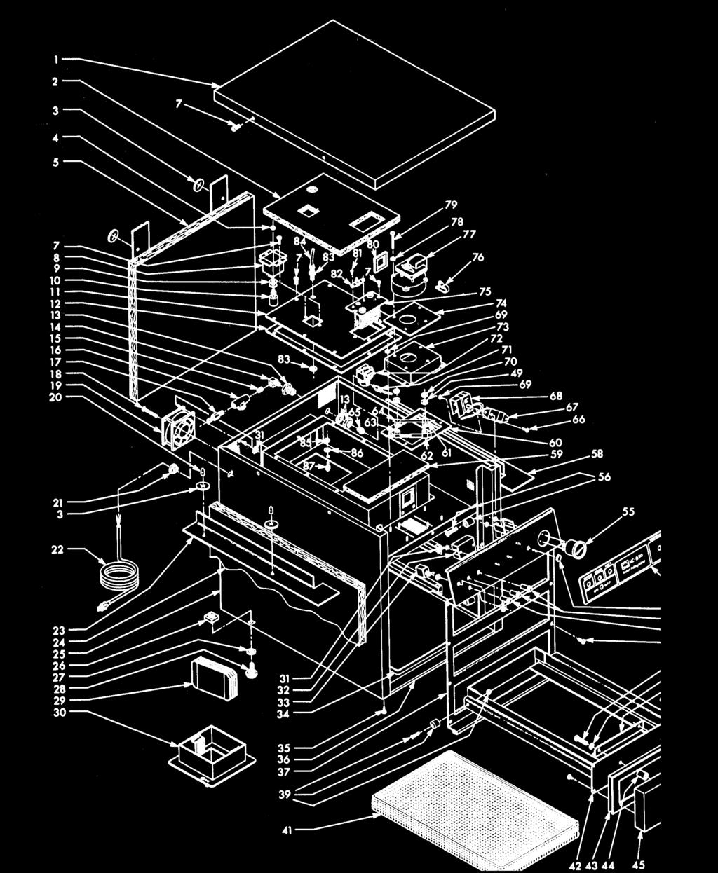
29 PARTS LIST MODEL HC HC-932 Item No. Part No. Description Quantity Item No. Part No. Description Quantity Top - Cabinet Signal Light Insulation - Access Cover 1 3 WA Washer Insulation (1 1/2 dia.) Signal Light - CE 1 4 NS Nut - Hex (1/8" straight pipe) Signal Light - CE Insulation - Back Signal Light Retainer - Insulation Rear 2 53 PL Button - Plug (1/2") 1 7 SC Screw (#8-32 x 1/2" PH Round Head) AR Decal - Control Panel Well - Float Switch Thermometer Spacer - Float Switch Liner Bearing & Hardware Float Switch Retainer - Insulation - Right Access Cover Assembly Insulation (9 x 3.75") Gasket - Heater Box Gasket Blower Box Bottom 1 13 FP Bulkhead Adaptor 1 61 EF Clamp (1/4 ID x 3/8") 1 14 FP Elbow (1/4 NPT x 1/4 NPT) 1 62 EF Clamp (7/16" ID x 3/8") 1 15 FP Nipple - Close (1/4" NPT x 7/8' ) 1 63 EF Clamp (5/16" 10 x 3/8") Strainer Water 1 64 EF Clamp (1/8" ID x 3/8") 1 17 FP Fitting (1/4 Tube to 1/4 NPT) 1 65 FP Nipple - Reducing 1 18 SC Screw (#6-32 x 2" PH Pan Head) AR 66 SC Screw (#6-32 x 1/4" PH Rd Hd) Fan - 120V Bracket Thermostat Mounting Fan - 240V Thermostat Kit 1 20 MS Cover - Stud 4 69 NS Nut - Hex (#10-24 Keps) AR 21 EF Relief - Strain 1 70 NS Nut - Hex (#10-24) Power Cord Assembly 1 71 FP Fitting (1/4" Tube to 1/8" Pipe) Power Cord Assembly - 240V Valve - Solenoid -120 V Power Cord Assembly - CE Valve - Solenoid V Retainer - Insulation Fan Box Assembly Insulation - Wrap/Around Gasket - Blower Box Top Encl.-Cab.-930-SN:EA & below Encl.-Cab.-930-SN:EA & above Heater - 120V Enclosure - Cabinet CE Heater - 240V Encl.-Cab.-932-SN:EA & below Heater - 120V Enclosed Encl.-Cab.-932-SN:EA & above 1 76 EF Clamp (1" ID x 1/2") Enclosure - Cabinet CE Blower - 120V 1 26 NS Nut Cage (3/8" - 16) Spacer - Leveler Foot Blower - 240V 50 HZ Foot 4 78 LW Lockwasher (#8 Internal) Baffle Water Pan 4 79 SC Screw (#8-32 x 2' PH Rd Hd) Water Pan Assembly Gasket - Blower 1 31 NS Nut - Hex (#6-32 Keps) AR 81 SC Screw (#8-AB x 3/8" PH Truss Hd) Timer - Delay High Limit Switch - Toggle 1 83 FP Union Bulkhead (1/ Tubing (1/4 ) Tray - Drip 1 85 NS Nut - Hex (1/4"-28) 2 35 SC Screw (#8-AB x 1/2" PH Pan Head) AR 86 LW Lockwasher (1/4 Split Ring) Base - Cabinet Stud - Threaded Faceplate Assembly 1 ** Gasket - Face Plate Faceplate Assembly - CE ** Legs Faceplate Assembly - CE ** Tray Drip (05324 only) Drawer Bearing & Hardware Basket - Wire - Small 3 MODEL (CFA) ** Pan 12 x 20 x 2.5 (alternate) Face Plate Stud Assy. 1 ** Rack - Wire Grid 10 x 18 (use w/05015) Water Pan Assy. 1 ** Tray Baffle for Pan Drawer Bearing 6 ** /2 SS Pan 12 x 10.5 x 2.5 (alternate) Drawer Frame Assy. 1 ** /2 wire grid (use w/05033) Drawer Assy Drawer Weld Assembly Nylatch Grommet Gasket - Drawer Nylatch Plunger Spacer Drawer Handle (use only w/ 25412) Left Drawer Rail Assy Drawer Front Assembly Right Drawer Rail Assy Handle Drawer Swivel-Water Pan Latch 1 47 SC Screw (#8-AB x 1/2" PH Pan Hd) AR Latch-Water Pan Retaining Support - Basket Baffle 4 49 LW Lockwasher (#10 Internal) AR 50 SC Screw (#19-24 x 1-1/2-for 25412) AR SC Screw (#10-32 x 1-1/2-for 31396) recommended parts/**not Shown AR
30
Henny Penny Island Warmer Model HMI-103 Model HMI-105 TECHNICAL MANUAL
 Henny Penny Island Warmer Model HMI-103 Model HMI-105 TECHNICAL MANUAL Section TABLE OF CONTENTS Page Section 1. TROUBLESHOOTING... 1-1 1-1. Introduction... 1-1 1-2. Safety... 1-1 1-3. Troubleshooting...
Henny Penny Island Warmer Model HMI-103 Model HMI-105 TECHNICAL MANUAL
 Henny Penny Island Warmer Model HMI-103 Model HMI-105 TECHNICAL MANUAL THIS PAGE INTENTIONALLY LEFT BLANK. Section TABLE OF CONTENTS Page Section 1. TROUBLESHOOTING... 1-1 1-1. Introduction... 1-1 1-2.
Henny Penny Display Counter Warmer Model CW-216/CW-114 TECHNICAL MANUAL
 Henny Penny Display Counter Warmer TECHNICAL MANUAL Section TABLE OF CONTENTS Section 1. TROUBLESHOOTING... 1-1 1-1. Introduction... 1-1 1-2. Safety... 1-1 1-3. Troubleshooting... 1-1 Page Section 2.
Henny Penny Blast Chiller/Freezer Models BCC/BCR-140 Models BCC/BCR-175 Models BFR/BCR-350
 Henny Penny Blast Chiller/Freezer Models BCC/BCR-140 Models BCC/BCR-175 Models BFR/BCR-350 TECHNICAL MANUAL Section TABLE OF CONTENTS Page Section 1. TROUBLESHOOTING... 1-1 1-1. Introduction... 1-1 1-2.
Henny Penny Electronic Bun Warmer Model BW-1 Model BW-4 Model BW-4 Model BW-4/3 Model BW-6 Model BW-8
 Henny Penny Electronic Bun Warmer Model BW-1 Model BW-4 Model BW-4 Model BW-4/3 Model BW-6 Model BW-8 SERVICE MANUAL LIMITED WARRANTY FOR HENNY PENNY EQUIPMENT Subject to the following conditions, Henny
Henny Penny Humidified Counter Warmer Model HCW-2 Model HCW-3 Model HCW-5 Model HCS-5 Model HCW-8 TECHNICAL MANUAL
 Henny Penny Humidified Counter Warmer Model HCW-2 Model HCW-3 Model HCW-5 Model HCS-5 Model HCW-8 TECHNICAL MANUAL Section TABLE OF CONTENTS Section 1. TROUBLESHOOTING... 1-1 1-1. Introduction... 1-1
Henny Penny Humidified Holding Cabinets Model HHC-980 Model HHC-983 TECHNICAL MANUAL
 Henny Penny Humidified Holding Cabinets Model HHC-980 Model HHC-983 TECHNICAL MANUAL LIMITED WARRANTY FOR HENNY PENNY EQUIPMENT Subject to the following conditions, Henny Penny Corporation makes the following
LIMITED WARRANTY FOR HENNY PENNY APPLIANCES
 LIMITED WARRANTY FOR HENNY PENNY APPLIANCES Subject to the following conditions, Henny Penny Corporation makes the following limited warranties to the original purchaser only for Henny Penny appliances
B.I.C.A Built-In Coffee Appliance
 B.I.C.A Built-In Coffee Appliance Automatic Coffee Brewer Parts & Service Models: 1033510, 1033510S & 1033511 3828 S. Main St. Los Angeles, CA 90037-1491 800-421-6860 310-787-5444 Fax 310-787-5412 e-mail:
OPERATOR S MODEL HCN-5 HHC-136 HEATED HOLDING CABINET REGISTER WARRANTY ONLINE AT
 OPERATOR S M A N U A L HEATED HOLDING CABINET MODEL HCN-5 HHC-136 REGISTER WARRANTY ONLINE AT WWW.HENNYPENNY.COM TABLE OF CONTENTS Section Page Section 1. INTRODUCTION... 1-1 1-1. Heated Holding Cabinet...
BUNN H5E H5M H5X BUNN-O-MATIC CORPORATION POST OFFICE BOX 3227 SPRINGFIELD, ILLINOIS PHONE: (217) FAX: (217)
 FAX: (217)") ! BUNN DISCONNECT FROM POWER SOURCE BEFORE REMOVAL OF ANY PANEL OR REPLACEMENT OF ANY COMPONENT! WARNING H5E H5M H5X WARNING Very Hot Water Use With Care!! ILLUSTRATED PARTS CATALOG Designs, materials,
! BUNN DISCONNECT FROM POWER SOURCE BEFORE REMOVAL OF ANY PANEL OR REPLACEMENT OF ANY COMPONENT! WARNING H5E H5M H5X WARNING Very Hot Water Use With Care!! ILLUSTRATED PARTS CATALOG Designs, materials,
!"" #$% "!&' ( ( ) *
 *") !"" #$% "!&' (( ) * Instruction Manual Models #2180, #2182, #2182H, #2191, #2193, #2195, #2196, #2197 & #2198 Part No. 38043 Revised June 1996 Model #2191 Model #2195 Cincinnati, OH 45241-4807 USA SAFETY
!"" #$% "!&' (( ) * Instruction Manual Models #2180, #2182, #2182H, #2191, #2193, #2195, #2196, #2197 & #2198 Part No. 38043 Revised June 1996 Model #2191 Model #2195 Cincinnati, OH 45241-4807 USA SAFETY
Instruction Manual. Portion Cup Cheese Warmer
 Instruction Manual Portion Cup Cheese Warmer Model No. 5581-00-100, 5581-01-100, and 5581-00-101 10700 Medallion Drive, Cincinnati, Ohio 45241-4807 USA 2017 Gold Medal Products Co. Part No. 74797 SAFETY
AHC-990 TECHNICAL MANUAL
 Henny Penny Humidified Holding Cabinets With Automatic Water Fill Model AHC-993 Model AHC-990 TECHNICAL MANUAL TABLE OF CONTENTS Section Page Section 1. TROUBLESHOOTING 1-1. Introduction... 1-1 1-1.
BUNN CWT-CS CWTF-CS BUNN-O-MATIC CORPORATION POST OFFICE BOX 3227 SPRINGFIELD, ILLINOIS PHONE: (217) FAX: (217)
 FAX: (217)") BUNN CWT-CS CWTF-CS ILLUSTRATED PARTS CATALOG Designs, materials, weights, specifications, and dimensions for equipment or replacement parts are subject to change without notice. BUNN-O-MATIC CORPORATION
BUNN CWT-CS CWTF-CS ILLUSTRATED PARTS CATALOG Designs, materials, weights, specifications, and dimensions for equipment or replacement parts are subject to change without notice. BUNN-O-MATIC CORPORATION
Dogeroo & Super Dogeroo
 Dogeroo & Super Dogeroo Instruction Manual Model #8002EX and #8003EX Part No. 87154EX Revised June 1996 Cincinnati, OH 45241-4807 USA SAFETY PRECAUTIONS This equipment is designed and sold for commercial
Model 2016, 2025, 2025BN, 2025ST Staging Cabinets Instruction Manual
 Model, 2025BN, 2025ST Staging Cabinets Instruction Manual Part No 53021 Cincinnati, OH 45241-4807 USA SAFETY PRECAUTIONS DANGER Machine must be properly grounded to prevent electrical shock to personnel.
OPERATIONS MAINTENANCE MANUAL
 OPERATIONS MAINTENANCE MANUAL COOK & HOLD OVEN SYSTEMS WITTCO MODEL NUMBERS 1300-AD-SS 1300-AD-SS-SPLIT LIMITED WARRANTY Wittco warrants the Products that it manufactures to be free from defects in materials
Instruction Manual. Astro Staging Cabinet
 Instruction Manual Astro Staging Cabinet 10700 Medallion Drive, Cincinnati, Ohio 45241-4807 USA 2017 Gold Medal Products Co. Part No. 40269 SAFETY PRECAUTIONS DANGER Machine must be properly grounded to
Mini-Cart Hot Dog Cooker Instruction Manual Model #8080 & #8081
 Mini-Cart Hot Dog Cooker Instruction Manual Model #8080 & #8081 Part No. 88914 Revised January 2002 Cincinnati, OH 45241-4807 USA SAFETY PRECAUTIONS 2 MODELS #8080 & #8081 OPERATING INSTRUCTIONS INSTALLATION
Instruction Manual. Dogeroo, Super Dogeroo, and Mini Dogeroo
 Instruction Manual Dogeroo, Super Dogeroo, and Mini Dogeroo Model No. 8102, 8103, 8108 10700 Medallion Drive, Cincinnati, Ohio 45241-4807 USA Part No. 87793 SAFETY PRECAUTIONS Page 2 INSTALLATION INSTRUCTIONS
DISCONTINUED VERSION Parts listed in this catalog may no longer be available. ILLUSTRATED PARTS CATALOG
 BUNN CWT-CS CWTF-CS DISCONTINUED VERSION Parts listed in this catalog may no longer be available. ILLUSTRATED PARTS CATALOG Designs, materials, weights, specifications, and dimensions for equipment or
DISCARD DECANTER IF: FAILURE TO COMPLY RISKS INJURY FUNNEL CONTENTS ARE HOT ILLUSTRATED PARTS CATALOG
 ! GMB-PS WARNING Disconnect from power source before removal of any panel or replacement of any component! FUNNEL CONTENTS ARE HOT CAUTION DISCARD DECANTER IF:. CRACKED. SCRATCHED. BOILED DRY. HEATED WHEN
OPERATOR S MODEL CW-216 CW-114 DISPLAY COUNTER WARMER REGISTER WARRANTY ONLINE AT
 OPERATOR S M A N U A L DISPLAY COUNTER WARMER MODEL CW-216 CW-114 REGISTER WARRANTY ONLINE AT WWW.HENNYPENNY.COM TABLE OF CONTENTS Section Page Section 1. INTRODUCTION... 1-1 1-1. Display Counter Warmer...
OPERATION, SERVICE & PARTS MANUAL
 OPERATION, SERVICE & PARTS MANUAL BROASTER 620NXP & 621 EASY BREADER Be sure ALL installers read, understand, and have access to this manual at all times. MODEL 620NXP MODEL 621 Genuine Broaster Chicken,
OPERATOR S MODEL HMI-103 HMI-105 ISLAND WARMER REGISTER WARRANTY ONLINE AT
 OPERATOR S M A N U A L ISLAND WARMER MODEL HMI-103 HMI-105 REGISTER WARRANTY ONLINE AT WWW.HENNYPENNY.COM TABLE OF CONTENTS Section Page Section 1. INTRODUCTION... 1-1 1-1. Island Warmers... 1-1 1-2.
OCH-SS series Direct Wired Units Indoor * and Outdoor Comfort Heaters
 1200 North Main Street Fostoria, OH 44830 Phone: 800-495-4525 Fax: 419-435-0842 A DIVISION OF www.fostoriaindustries.com OCH-SS series Direct Wired Units Indoor * and Outdoor Comfort Heaters *EXCLUDING
Instruction Manual. 36 in. and 42 in. Popcorn Staging Cabinets
 Instruction Manual 36 in. and 42 in. Popcorn Staging Cabinets Model Series 2856 and 2855 42 in. Model 2855-00-000 36 in. Model 2856-00-000 10700 Medallion Drive, Cincinnati, Ohio 45241-4807 USA 2016 Gold
Instruction Manual. Nacho Cheese Dispenser and Warmer
 Instruction Manual Nacho Cheese Dispenser and Warmer 10700 Medallion Drive, Cincinnati, Ohio 45241-4807 USA 2013 Gold Medal Products Co. Part No. 36060 SAFETY PRECAUTIONS Page 2 INSTALLATION INSTRUCTIONS
DISCARD DECANTER IF: FUNNEL CONTENTS ARE HOT FAILURE TO COMPLY RISKS INJURY
 ! BUNN GMB-PS WARNING Disconnect from power source before removal of any panel or replacement of any component! FUNNEL CONTENTS ARE HOT CAUTION DISCARD DECANTER IF:. CRACKED. SCRATCHED. BOILED DRY. HEATED
Hot Dog Hutch. Models HDH-3, HDH-3DR, & HDH-4 owner s manual. Manufacturing Numbers:
 Hot Dog Hutch Models HDH-3,, & HDH-4 owner s manual Manufacturing Numbers: 9300100, 9300101, 9300102, 9300104, 9300106, 9300108, 9300112, 9300116, 9300118, 9300120, 9300124, 9300125, 9300130, 9300132 www.ajantunes.com
5300, 5300CH, 5300EX, 5300FN
 Part No. 36060 Revised APRIL 2008 5300, 5300CH, 5300EX, 5300FN Instruction Manual SAFETY PRECAUTIONS FORWARD This manual covers the model # 5300, 5300FN, 5300CH & 5300EX NACHO CHEESE DISPENSER. You can
OPERATING MANUAL/ INSTALLATION
 NHW- 15 HOT WATER MACHINE OPERATING MANUAL/ INSTALLATION 120/240 V 1650/6600 W US 120/240 V 1350/5500 W CAN CONVERTIBLE 2 GA LLON DRIP TRAY INCLUDED ADVANCED TEMPERATURE CONTROL TVT TECHNOLOGY NEWCO ENTEPRISES
SERVICE MANUAL. Bradford White ElectriFLEX HD (Heavy Duty) Commercial Electric Water Heater CEHD SERIES Immersion Thermostat Models
 Commercial Electric Water Heater CEHD SERIES Immersion Thermostat Models") Bradford White ElectriFLEX HD (Heavy Duty) Commercial Electric Water Heater CEHD SERIES Immersion Thermostat Models SERVICE MANUAL Troubleshooting Guide and Instructions for Service (To be performed ONLY
Bradford White ElectriFLEX HD (Heavy Duty) Commercial Electric Water Heater CEHD SERIES Immersion Thermostat Models SERVICE MANUAL Troubleshooting Guide and Instructions for Service (To be performed ONLY
OPERATION MANUAL ODS 300 ODS 310
 300 Series Oil Disposal Shuttle OPERATION MANUAL ODS 300 ODS 310 FM07-635J Table of Contents Safety... iii Chapter 1 Introduction...1 1.1 Introduction...1 1.2 Technical Support...1 1.3 Model Configuration
Cheese Display Case. Instruction Manual Model #5580BV2 and Model #5580BV3 Model #5582 and Model #5583. Cincinnati, OH USA.
 Instruction Manual Model #5580BV2 and Model #5580BV3 Model #5582 and Model #5583 Part No. 38475 Revised June 1996 Model #5582 Model #5583 Cincinnati, OH 45241-4807 USA SAFETY PRECAUTIONS This equipment
DryAire DRYING CABINET
 CONSUMER SERVICES TECHNICAL EDUCATION GROUP PRESENTS L-72 DryAire DRYING CABINET Model LMA1053L JOB AID Part No. 8178202 FORWARD This Whirlpool Job Aid, DryAire Drying Cabinet, (Part No. 8178202), provides
Instruction Manual. Cheese Warmer with Pump
 Instruction Manual Cheese Warmer with Pump 10700 Medallion Drive, Cincinnati, Ohio 45241-4807 USA 2013 Gold Medal Products Co. Part No. 38298 SAFETY PRECAUTIONS Page 2 INSTALLATION INSTRUCTIONS Inspection
Instruction Manual. Cheddar Easy All-In-One Cheese Corn Shop
 Instruction Manual Cheddar Easy All-In-One Cheese Corn Shop Model No. 2703-00-000 10700 Medallion Drive, Cincinnati, Ohio 45241-4807 USA 2017 Gold Medal Products Co. Part No. 110028 SAFETY PRECAUTIONS
TURBO Fiberglass Cone Fan and Grill Fan 48'' Belt Drive. Installation & Operator s Instruction Manual
 TURBO Fiberglass Cone Fan and Grill Fan 48'' Belt Drive Installation & Operator s Instruction Manual July 1998 MV1383B Chore-Time TURBO TM Fan Extended Warranty Chore-Time Equipment warrants new TURBO
User s Manual and Operating Instructions
 User s Manual and Operating Instructions Model Numbers: PT-18W-DDF-A, PT-20F-DDF-A, PT-20S-DDF, PT-24O-DDF, PT-24-DDF, PT-24-DDF-F, PT-30-DDF, PT-30P-DDF-A, PT-30P-DDF-AF READ AND SAVE THESE INSTRUCTIONS
Instruction Manual. Table Top Steamer Cart
 Instruction Manual Table Top Steamer Cart 10700 Medallion Drive, Cincinnati, Ohio 45241-4807 USA 2015 Gold Medal Products Co. Part No. 88586 SAFETY PRECAUTIONS DANGER Machine must be properly grounded
OPERATION, SERVICE & PARTS MANUAL
 OPERATION, SERVICE & PARTS MANUAL BROASTER 620N & 621 EASY BREADER Be sure ALL installers read, understand, and have access to this manual at all times. MODEL 620N MODEL 621 Genuine Broaster Chicken, Broasted,
Service Parts, Kits and Accessories
 The parts identification guides on the following pages have been designed to give a quick reference to component parts used on pilot ignition agricultural building heaters. The guides identify components
Camarillo 52 Ceiling Fan
 Owner s Manual Camarillo 52 Ceiling Fan Part # 269263, 269259, 269287 Model # 32091, 32092, 32087 Exclusively Distributed by: HD Supply Facilities Maintenance, Ltd. Atlanta, GA 30339 2017 Made in China
User s Manual and Operating Instructions
 User s Manual and Operating Instructions Model Numbers: CL-30P-DDF, CL-20F-DDF, CL-24O-DDF, CL-30-DDF READ AND SAVE THESE INSTRUCTIONS IMPORTANT: Read and understand all of the directions in this manual
Getz Equipment Innovators 450 lb Dual Portable Dry Chemical Fill System
 Getz Equipment Innovators 450 lb Dual Portable Dry Chemical Fill System 1 Revised 11/18/10 2320 Lakecrest Drive, Pekin IL 61554 PH. (888) 747-4389 Fax (309) 495-0625 Website: www.getzequipment.com LIMITED
E N T E R P R I S E S INSTALLATION, OPERATION, AND SERVICE MANUAL FOR GK SERIES BREWERS
 N E W C O E N T E R P R I S E S INSTALLATION, OPERATION, AND SERVICE MANUAL FOR GK SERIES BREWERS Man Pt No 701278 050306 GKDF-4 GKF-3 Model Warmers Width Length Height Weight Watts Amps GKF-1 1 9-1/2"
DISCOVERY Instruction Manual Model #2556
 Part No. 69922 Revised May 2002 DISCOVERY Instruction Manual Model #2556 Cincinnati, OH 45241-4807 USA www.gmpopcorn.com Safety Precautions 2 INSTALLATION INSTRUCTIONS Inspection of Shipment: Unpack the
01550-RevG IMPORTANT INSTRUCTIONS WEBSITE MANUAL
 01550-RevG-082712 IMPORTANT INSTRUCTIONS WEBSITE MANUAL english model: FSAF Food Server Advantage TM Fudge/Caramel 120V Series 12A 85070 Unit Set-Up Always clean unit thoroughly before first use. See UNIT
Torrena 42 Ceiling Fan
 Torrena 42 Ceiling Fan Owner s Manual Part # 269268, 269269 Model # 32096, 32097 Exclusively Distributed by: HD Supply Facilities Maintenance, Ltd. Atlanta, GA 30339 2017 Made in China If you are experiencing
Condiment Warmer. Instruction Manual Models #2252EX & #2253EX. Cincinnati, OH USA. Model #2252EX. Model #2253EX
 Condiment Warmer Instruction Manual Models #2252EX & #2253EX Part No. 38187EX Revised June 1996 Model #2252EX Model #2253EX Cincinnati, OH 45241-4807 USA SAFETY PRECAUTIONS This equipment is designed and
Lubi Submersible Condensate Removal Pumps
 Please read and retain these instructions for future reference. Kindly read this manual carefully before making any effort to assemble, install, operate or maintain our pumps. Please protect yourself and
6 oz. Kettle Poppers With / Love My Popper Kettle Popcorn Machine Instruction Manual Models: 1871,2660,2661
 Part No. 49217 Revised: June 2004 With / Love My Popper Kettle Popcorn Machine Instruction Manual Models: 1871,2660,2661 Cincinnati, OH 45241-4807 USA SAFETY PRECAUTIONS 2 Models: 1871,2660,2661 INSTALLATION
R Series B & T2 Model
 FRONT R Series B & T2 Model Fan Forced Wall Heaters 4-1/4 (108mm) NOTE: Knockouts in top same dimensions 3-1/4 3-1/4 (108mm) (108mm) as bottom 16-7/8 (429mm) 13-7/8 (352mm) BOTTOM 13-7/8 (352mm) 7-3/4
OWNERS MANUAL. DrugPress 100 Operation and Service. Bienfang EQUIPMENT
 OWNERS MANUAL DrugPress 100 Operation and Service Bienfang EQUIPMENT CONTENTS Important Safeguards 3 Press Features and Specifications 3 Identification of Controls 4 Installation and Preparation 4 Procedures
52 CEILING FAN. Owner s Manual Models #50336, 50337
 52 CEILING FAN Owner s Manual Models #50336, 50337 If a problem cannot be remedied or you are experiencing difficulty in installation, please contact the Service Department: 1-877-706-3267, 9 a.m.- 5 p.m.
OPERATOR S MODEL HHC-901 HHC-904 HEATED HOLDING CABINET REGISTER WARRANTY ONLINE AT
 OPERATOR S M A N U A L HEATED HOLDING CABINET MODEL HHC-901 HHC-904 REGISTER WARRANTY ONLINE AT WWW.HENNYPENNY.COM TABLE OF CONTENTS Section Page Section 1. INTRODUCTION... 1-1 1-1. Heated Holding Cabinet...
Hot Dog Roller Grills
 Part No. 87630 Hot Dog Roller Grills Model No. 8022, 8022PE, 8023, 8023SL, 8023PE, 8024, 8024PE, 8024SL, 8025, 8025SL Cincinnati, OH 45241-4807 USA SAFETY PRECAUTIONS DANGER Machine must be properly grounded
Instruction Manual. Spiral Slicer
 Instruction Manual Spiral Slicer Model No. 5280-00-100 10700 Medallion Drive, Cincinnati, Ohio 45241-4807 USA 2017 Gold Medal Products Co. Part No. 82876 Table of Contents... 1 SAFETY PRECAUTIONS... 3
Frosty Factory of America, Inc.
 Frosty Factory of America, Inc. 2301 S. Farmerville St., Ruston, LA 71270 frostyfactory.com (318) 255-1162 (800) 544-4071 (318) 255-1170 fax Auto Fill System & Tank Service Manual All technical data, pictures
Instruction Manual. Double Candy Apple Cooker
 Instruction Manual Double Candy Apple Cooker Model No. 4416 10700 Medallion Drive, Cincinnati, Ohio 45241-4807 USA 2014 Gold Medal Products Co. Part No. 46841 SAFETY PRECAUTIONS DANGER Machine must be
Roller Dog. Instruction Manual Model #8023, Model #8024 and Model #8025. Cincinnati, OH USA. Model #8024. Model #8025
 Roller Dog Instruction Manual Model #8023, Model #8024 and Model #8025 Part No. 67141 Revised June 1996 Model #8024 Model #8025 Cincinnati, OH 45241-4807 USA SAFETY PRECAUTIONS This equipment is designed
 WARNING!! The attached Gold Medal Manual is for reference only and is not intended for any other purpose. The information contained in these on line manuals is subject to change at any time. Improvements
P-60 and 60 Special. Popcorn Machine Instruction Manual Model #1866, #2085, #2086 and #2656. Cincinnati, OH USA
 Part No. 49064 Revised: March 2004 P-60 and 60 Special Popcorn Machine Instruction Manual Model #1866, #2085, #2086 and #2656 Models #1866 and #2086 Models #2085 and #2656 Cincinnati, OH 45241-4807 USA
Floss Machine Instruction Manual Model #3017, #3017SS AND #3077
 Part No. 42131 Revised: May 2004 Floss Machine Instruction Manual Model #3017, #3017SS AND #3077 Econo-Floss Floss-Maxx Cincinnati, OH 45241-4807 USA INTRODUCTION Your Floss Machine warranty is described
Installation Instructions / Warranty
 Installation Instructions / Warranty IP C 04210000 04211000 04212000 IP S 04203000 04204000 04205000 IP E 04199000 04200000 04201000 IP Trim Sets Valve trim only IP C 04212000 IP E 04201000 IP S 04205000
ion Genesis Pump Controller
 High Water Alarm Document No.: IONG_OM Page 1 of 7 Table of Contents Safety Precautions.......................... 1 General Overview.......................... 1 Installation.................................2
MANUFACTURING NUMBERS: CORN CAROUSEL. Model CC-19 Series P/N /99. Owner s Manual
 MANUFACTURING NUMBERS: 9500410 9500412 C US Model CC-19 Series 9500400 P/N 1010730 10/99 Owner s Manual A.J. Antunes & Co. Owner Information...1 General...1 Warranty Information...1 Service/Technical Assistance...2
CMA Dishmachines Knott Avenue Garden Grove, CA Undercounter High Temperature Dishwasher. Service Replacement Parts.
 CMA Dishmachines 1700 Knott Avenue Garden Grove, CA 981 Toll Free: 1- (800) 8-617 Fax: 1- (71) 89-11 Service Replacement Parts Undercounter High Temperature Dishwasher Model: UC6e M Machine Serial No.
36 & 48 E-Z Cone Fan. Installation & Operator s Instruction Manual (Direct Drive)
") 36 & 48 E-Z Cone Fan Installation & Operator s Instruction Manual (Direct Drive) September 1997 MV1433C Chore-Time Warranty Chore-Time Equipment warrants each new product manufactured by it to be free
36 & 48 E-Z Cone Fan Installation & Operator s Instruction Manual (Direct Drive) September 1997 MV1433C Chore-Time Warranty Chore-Time Equipment warrants each new product manufactured by it to be free
e Heater/Exhaust Fan/Light User s Guide
 e Heater/Exhaust Fan/Light User s Guide abflh70l, BFLH85L Item Stock Number(s): BFLH70L, BFLH85L IMPORTANT INSTRUCTIONS - OPERATING MANUAL READ AND SAVE THESE INSTRUCTIONS READ CAREFULLY BEFORE ATTEMPTING
InstructIon Manual KrEs EQuIPMEnt stands
 Instruction Manual Instruction Manual SELF-CONTAINED AND REMOTE Kairak KRES model refrigerated equipment stand units are available in many lengths from 36 to 120 inches long. These units are available
ALTAIR II CONVECTION STEAM COOKER PARTS AND SERVICE MANUAL
 ALTAIR II CONVECTION STEAM COOKER PARTS AND SERVICE MANUAL EFFECTIVE MAY, 0 Superseding All Previous Parts Lists. The Company reserves the right to make substitution in the event that items specified are
Large Combo Warmer Instruction Manual Model #2206
 Part No. 40208 Revised June 1997 Large Combo Warmer Instruction Manual Model #2206 Cincinnati, OH 45241-4807 USA SAFETY PRECAUTIONS CHECKING SHIPMENT The popcorn machine is shipped in a corrugated carton.
DISCARD DECANTER CAUTION . CRACKED . BOILED DRY. HEATED WHEN EMPTY. USED ON HIGH FLAME FAILURE TO COMPLY RISKS INJURY FUNNEL CONTENTS ARE HOT PN: 658
 PN: 658 IF: PN: 658! IF: PN: 658! IF: BUNN C, CT & CTF! CAUTION WARMERS AND SURFACES ARE HOT C SERIES READY CAUTION DISCARD DECANTER. CRACKED. SCRATCHED. BOILED DRY. HEATED WHEN EMPTY. USED ON HIGH FLAME.
HEATED DISPLAY CABINET
 R INSTALLATION AND OPERATING INSTRUCTIONS HEATED DISPLAY CABINET MODEL: HDC- WARNING: Improper installation, adjustment, alteration, service or maintenance can cause property damage, injury or death. Read
CSD-1 CRN Electra Steam, Inc. Instruction Manual for JR06 Steam Generator, JG- and JJ- Models
 ASME CSD-1 CRN Electra Steam, Inc. Instruction Manual for JR06 Steam Generator, JG- and JJ- Models RETAIN THIS OPERATING MANUAL WITH BOILER. DO NOT DISCARD READ THIS FIRST: The safeguards and instructions
Wax Base Heater & Dispenser
 Wax Base Heater & Dispenser Service Manual Models: IDWB2/0900, IDWB2/0775, IDWB3/0900, IDWB3/0775, IDWB4/0900, IDWB4/0775 Introduction............................................................................
OPERATOR S MODEL MPC-21L MPC-222 MULTIPURPOSE PASS-THRU HOLDING CABINET. Read instructions before operating the appliance
 OPERATOR S M A N U A L MULTIPURPOSE PASS-THRU HOLDING CABINET MODEL MPC-21L MPC-222 REGISTER WARRANTY ONLINE AT WWW.HENNYPENNY.COM Read instructions before operating the appliance TABLE OF CONTENTS Section
HOT DOG STEAMER Instruction Manual Models: 8007 & 8012
 Part No. 87202 Revised: November 2005 HOT DOG STEAMER Instruction Manual Models: 8007 & 8012 Model # 8012 Shown Cincinnati, OH 45241-4807 USA SAFETY PRECAUTIONS 2 Model# 8007 & 8012 INSTALLATION INSTRUCTIONS
e Bath Fan with Light User s Guide
 e Bath Fan with Light User s Guide abfl125rok Item Stock Number(s): BFL125ROK IMPORTANT INSTRUCTIONS - OPERATING MANUAL READ AND SAVE THESE INSTRUCTIONS READ CAREFULLY BEFORE ATTEMPTING TO ASSEMBLE, INSTALL,
Part No Revised: June TS1 TOASTER SYSTEM Instruction Manual Models # 5700 AND # 5700SF
 Part No. 44162 Revised: June 2006 TS1 TOASTER SYSTEM Instruction Manual Models # 5700 AND # 5700SF SAFETY PRECAUTIONS 2 TOASTER SYSTEM INSTALLATION CHECKING SHIPMENT Unpack the unit from the shipping container
WARMING AND MERCHANDISING CABINET
 WARMING AND MERCHANDISING CABINET MODEL 695 MODEL 695-S (Two door unit shown) (Single door unit shown) Snack foods have to be hot and moist to be appealing. Cold won t do... Dry won t do. Wisco s model
OPERATIONS FOOD HOLDING & TRANSPORT CABINETS. wîttco foodservice. equipment
 OPERATIONS MAINTENANCE MANUAL FOOD HOLDING & TRANSPORT CABINETS WITTCO MODEL NUMBERS 1220-105-2-BC 1220-105-3-BC 1220-105-4-BC A A wîttco foodservice equipment F-41009 LIMITED WARRANTY Wittco warrants
Floss Machine Instruction Manual Model #3024
 Part No. 42543 Revised: May 2004 Floss Machine Instruction Manual Model #3024 Cincinnati, OH 45241-4807 USA Safety Precautions Floss Machines 2 INTRODUCTION Your Floss Machine warranty is described on
AMERICA AMERICA 52 CEILING FAN INSTALLATION AND OPERATION MANUAL
 AMERICA AMERICA 52 CEILING FAN INSTALLATION AND OPERATION MANUAL Ceiling Fan Weight Including Accessories: 21.00 Lbs. READ AND SAVE THESE INSTRUCTIONS TABLE OF CONTENTS Tools and Materials Required...
WET/DRY VACUUM. QUEST for Continuous Improvement Windsor s Quality Management System is Certified ISO MODEL: T1. Operating Instructions (ENG)
") WET/DRY VACUUM Operating Instructions (ENG) MODEL: T1 y QUEST for Continuous Improvement Windsor s Quality Management System is Certified ISO 9001. Read these instructions before operating the machine.
WET/DRY VACUUM Operating Instructions (ENG) MODEL: T1 y QUEST for Continuous Improvement Windsor s Quality Management System is Certified ISO 9001. Read these instructions before operating the machine.
Popcorn Machine Instruction Manual Model #2551EX
 Part No. 49793EX Revised January 2004 Popcorn Machine Instruction Manual Model #2551EX Cincinnati, OH 45214-2089 USA. SAFETY PRECAUTIONS INSTALLATION INSTRUCTIONS SETUP Remove all packing material and
SPA BLOWER OWNER'S MANUAL XXXX, XXXX, XXXX, XXXX, XXXX, XXXX fax
 SPA BLOWER OWNER'S MANUAL 80015-XXXX, 80016-XXXX, 80017-XXXX, 80018-XXXX, 80019-XXXX, 80020-XXXX fax 888.610.3839 2015 323300-015 6/15 THIS PAGE INTENTIONALLY LEFT BLANK. 2 Operating Instructions and Parts
MANUAL FOOD HOLDING & TRANSPORT CABINETS WITTCO MODEL NUMBERS
 O P E R A T I O N S M A I N T E N A N C E MANUAL FOOD HOLDING & TRANSPORT CABINETS WITTCO MODEL NUMBERS 1826-4 1826-7-BC-IS 1826-7 1826-13-BC-IS 1826-7-BC 1826-15-BC-IS 1826-13-BC 1826-15-BC 1826-40-BC
(3 plastic wire connectors,blade balancing kit, 2 extra mounting screws #10-32 for outlet box.)
") Excel Lighting & Manufacturing Ltd. Lifetime Limited Warranty Excel Lighting & Manufacturing Ltd. Warrants the fan motor to be free from defects in workmanship and material present at time of shipment
Excel Lighting & Manufacturing Ltd. Lifetime Limited Warranty Excel Lighting & Manufacturing Ltd. Warrants the fan motor to be free from defects in workmanship and material present at time of shipment
ELECTRICAL DATA: FEATURES: SHIPPING INFORMATION: FOOD WARMING/ MERCHANDISING CABINET. 15 Width 7 Width
 FOOD WARMING/ MERCHANDISING CABINET MODEL 323HH MODEL 323HH-7 15 Width 7 Width With the ability to hold a point-of-purchase advertisement, these sleek, compact warmers are sure to draw eye catching attention.
MC MC MC MC MC833130
 Pic-A-Vac Model: MC832085 MC833085 MC832105 MC833105 MC832130 MC833130 OPERATION SERVICE PARTS CARE Revised 8/01 FOR COMMERCIAL USE ONLY IMPORTANT SAFETY INSTRUCTIONS When using an electrical appliance,
SINGLE BUNN-O-MATIC CORPORATION POST OFFICE BOX 3227 SPRINGFIELD, ILLINOIS PHONE: (217) FAX: (217)
 FAX: (217)") ! SINGLE WARNING DISCONNECT FROM POWER SOURCE BEFORE REMOVAL OF ANY PANEL OR REPLACEMENT OF ANY COMPONENT! PRIOR TO S/N SNG000000 gal gal gal START ON / WARMER SELECTOR READY! BUNN MANUFACTURED BY BUNN-O-MATIC
! SINGLE WARNING DISCONNECT FROM POWER SOURCE BEFORE REMOVAL OF ANY PANEL OR REPLACEMENT OF ANY COMPONENT! PRIOR TO S/N SNG000000 gal gal gal START ON / WARMER SELECTOR READY! BUNN MANUFACTURED BY BUNN-O-MATIC
3500 SERIES CONVECTION STEAM COOKER PARTS AND SERVICE MANUAL
 3500 SERIES CONVECTION STEAM COOKER PARTS AND SERVICE MANUAL EFFECTIVE JULY 30, 2014 Superseding All Previous Parts Lists. The Company reserves the right to make substitution in the event that items specified
Floss Machines Instruction Manual Models #3017, #3017SS, 3024, and #3077 For Machines Manufactured after July 2007
 Part No. 42131 Floss Machines Instruction Manual For Machines Manufactured after July 2007 Cincinnati, OH 45241-4807 USA Installation Instructions Inspection of Shipment: Unpack all cartons and check
I N ST R UC T I ON HCM450 CUTTER MIXER MODEL. FORM (Apr. 2002) S. RIDGE AVENUE TROY, OHIO
 S. RIDGE AVENUE TROY, OHIO") I N ST R UC T I ON S HCM450 CUTTER MIXER MODEL HCM450 ML-134170 701 S. RIDGE AVENUE TROY, OHIO 45374-0001 937 332-3000 www.hobartcorp.com FORM 34772 (Apr. 2002) Installation, Operation and Care of Model
I N ST R UC T I ON S HCM450 CUTTER MIXER MODEL HCM450 ML-134170 701 S. RIDGE AVENUE TROY, OHIO 45374-0001 937 332-3000 www.hobartcorp.com FORM 34772 (Apr. 2002) Installation, Operation and Care of Model
24 & 30 Quiet Design Oscillating Wall Mount Fan
 Operating Instructions & Parts Manual Models: 99538, 99539 Please read and save these instructions. Read carefully before attempting to assemble, install, operate or maintain the product described. Protect
VP17A BUNN OPERATING & SERVICE MANUAL
 BUNN VP17A OPERATING & SERVICE MANUAL BUNN-O-MATIC CORPORATION POST OFFICE BOX 3227 SPRINGFIELD, ILLINOIS 62708-3227 PHONE: (217) 529-6601 FAX: (217) 529-6644 10860.0001C 9/00 1997 Bunn-O-Matic Corporation