Air to water heat pump
|
|
|
- Edith Sparks
- 5 years ago
- Views:
Transcription
 GmbH Werftstrasse 20 40549 Düsseldorf - Germany Subject to change without notice Non contractual document")
1 Document ~ 04/03/2013 Air to water heat pump FR EN Split System (single phase type) Hydraulic unit WS *A050DD6 WS *A100DD6 WG *A050DD6 WG *A100DD6 Outdoor unit WO *A060LDC WO *A080LDC WO *A100LDT Maintenance Document Intended for professional use Fujitsu General (Euro) GmbH Werftstrasse Düsseldorf - Germany Subject to change without notice Non contractual document 04/03/2013
2 Contents 1 Control and test Control of Electric Backups Sensor and Input Test Mode Faults Fault List Service parts information 3 : Outdoor unit Hydraulic Unit Fault... 5 electronic expansion valve (EEV) Outdoor Unit Fault Service parts information 4 : Outdoor unit 2.2 Outdoor Unit Clearing... 8 solenoid valve (SV) Failures with Error Code Service parts information 5 : Outdoor unit fan Failures With No Error Code motor Sensor Values Service parts information 6 : Active filter Outdoor Unit Temperature Sensors module (Only for WO*A080LDC and Hydraulic Unit Temperature Sensors WO*A100LDT models) Service parts information Service parts information 7 : IPM (mounted Service parts information 1 : Compressor.. 32 on Transistor PCB, Only for WO*A080LDC Service parts information 2 : Inverter and WO*A100LDT models) compressor Operating Limits Failures Hydraulic, Electric and Refrigeration 3.2 Compressor Operating Checks Systems Refrigeration Circuit Leak Test Hydraulic System Electrical System Refrigeration System Troubleshooting Control Settings General Heat Pump Functions Function Table Supplementary source Adjustment Function Details DHW Tank Functions (with DHW kit or with Date and Time Functions integrated DHW models) User Interface Functions Configuration Functions Time Program Functions (heating circuit 1 & Error Functions , DHW, cooling) Maintenance / Special Operating Mode Heating Circuit 1 & 2 Functions Functions Cooling Circuit 1 Functions Input / Output Testing Functions DHW Functions (with DHW kit or with Status Functions integrated DHW models) Generator Diagnosis Functions Swimming Pool Functions Consumer Diagnosis Functions Maintenance services Hydraulic checks Descaling Maintenance of the DHW tank 5.3 Checking the outdoor unit (Integrated DHW models) Emptying the hot water tank Electrical checks Maintenance (integrated DHW models Emptying the hydraulic unit ACI check Distribution valve... 92
3 7 Disassembly Process of Outdoor Unit WO*A060LDC and WO*A080LDC SERVICE PANEL removal Appearance TOP PANEL removal TOP PANEL removal VALVE COVER removal FRONT PANEL removal MAIN PCB and POWER PCB removal VALVE COVER removal TRANSISTOR PCB and ACTPM PCB MAIN PCB, TRANSISTOR PCB, and ACTPM removal removal FAN MOTOR removal FAN MOTOR removal RIGHT PANEL removal CABINET RIGHT ASSY removal THERMISTOR removal THERMISTOR removal SOLENOID COIL removal SOLENOID COIL removal EEV COIL removal EEV COIL removal PRESSURE SENSOR removal PRESSURE SENSOR removal COMPRESSOR removal COMPRESSOR removal Precautions for exchange of refrigerantcycle-parts 7.2 WO*A100LDT Appearance Maintenance Document
4 1 Control and test 1.1 Control of Electric Backups H 33 EX 1 EX 2 EX 3 Outdoor Unit Fault Load-shedding (EJP) Off-peak/peak hours External fault (369) (370) 0 V 230 V 230 V 0 V 230 V 0 V 230 V EJP lock signal (l 2920) "released" "locked" HEAT PUMP OFF ON ON OFF ON ON ON OFF DHW auxiliary ON (1) ON OFF OFF ON OFF ON OFF 1st stage elec. auxiliary ON (2) ON OFF OFF ON ON ON OFF 2nd stage elec. auxiliary ON (2) ON OFF OFF ON ON ON OFF Boiler backup ON (2) ON ON ON ON ON ON OFF (1) subject to authorization by EX2 (2) provided the outdoor temperature is less than the setting on "2884 or 3700" (+2 from the beginning) 1.2 Sensor and Input Test Mode LINE SENSOR INPUT OUTPUT WATERSTAGE 7700 QX Relay test 7710 UX1 Output test 7712 UX1 PWM-Signal 7722 DO2 Cooling mode 7723 D3 Heat pump 7724 UX3 Output test ("Inverter" command) 7725 UX3 Voltage signal (Ux3) 7820 BX1 Sensor temp (HP flow temperature) 7821 BX2 Sensor temp (HP return temperature) 7822 BX3 Sensor temp (DHW temperature) 7823 BX4 Sensor temp (Outside temperature) 7911 EX1 Input (Power shedding, EJP) 7912 EX2 Input (Tariffs day/night) 7913 EX3 Input (External fault) 7973 BX31 Sensor temp (Mixing circuit temp.) 7976 BX34 Sensor temp (Swimming pool exchanger temperature) 7996 H33 Contact state 4 Maintenance Document
5 2 Faults 2.1 Fault List Hydraulic Unit Fault Faults which occur on the Hydraulic Unit are shown by the symbol. Press the info key for details on the cause of the fault. The following information is displayed : Description of the error Location of the error (sensor or contact) Reset. Depending on its type, the fault can be manually or automatically deleted: Manual delete: the text displayed when pressing the info key shows "reset?". Press once, the yes flashes; press again to confirm deletion of the fault. Faults whose deletion is automatic are automatically reset. Heat pump op: shows whether or not the heat pump operates despite the fault. Location Reset No.: Designation of error HP op (connection) Manual Auto 10: Outdoor sensor X86 No No Yes 33: Flow sensor HP X70 No No Yes 44: Return sensor HP X70 No No Yes 50: DHW sensor 1 X84 No No Yes 60: Room sensor 1 No No Yes 65: Room sensor 2 No No Yes 105: Maintenance message No No Yes 121: Flow temp HC1 (too low) No No Yes 122: Flow temp HC2 (too low) No No Yes 127: Legionella temp No No Yes 369: External fault (safety component) No 370: Thermodynamic source* No No No No connection the polarity of the room sensor is not respected. - - No * A fault in the outdoor unit is indicated by LED located on the Hydraulic Unit interface board. LED display LED 2 (green) LED 1(red) Fault description Clear 1 Flash 1 Flash Communication error between Hydraulic Unit and Outdoor unit. 1, 2 4 Flashes 1 Flash Heat pump capacity signal error (Open or short). 4 4 Flashes 2 Flashes Hydraulic Unit heat-exchange thermistor Error. 5 6 Flashes 4 Flashes Active filter error Flashes 4 Flashes PFC error 21 7 Flashes 1 Flash Discharge thermistor error. 7 7 Flashes 2 Flashes Compressor thermistor error Flashes 3 Flashes Heat-exchange thermistor (outlet) error. 8 7 Flashes 4 Flashes Outdoor thermistor error. 9 7 Flashes 8 Flashes Expansion valve thermistor error Flashes 4 Flashes Current sensor error Flashes 6 Flashes Pressure sensor error Flashes 4 Flashes Current trip Flashes 5 Flashes Detection of compressor position error. Compressor start up error Flashes 7 Flashes Outdoor unit fan motor error Flashes 1 Flash Discharge temperature protection Flashes 3 Flashes Compressor temperature protection Flashes 5 Flashes Low pressure abnormal. 26 Continuous flashing Pump down operation. (1 sec ON / 1 sec OFF) ON OFF During defrost OFF OFF Normal operation / Operation stops Maintenance Document
6 Faults external to the heat pump Any safety device (e.g. thermostat pressure switch) wired to input Ex3 (E20) allows external problems to be reported and the heat pump to be immediately Figure 1: Location of DIP switches and diodes on the hydraulic unit interface card stopped. For example, a safety thermostat on the heating floor can be wired to input Ex3 (E20) to avoid excessively high temperatures in the floor. Figure 2: Typical Wiring of External Devices 6 Maintenance Document
7 2.1.2 Outdoor Unit Fault When the system is switched back on after a power outage, the Hydraulic Unit may display fault 370 for a few tens of seconds. This is not a serious problem. It simply means that the outdoor unit is running its tests. Once the tests have been completed, the fault should disappear. Faults are coded by LED located on the hydraulic unit interface board (see page 5) Maintenance Document
8 2.2 Outdoor Unit Clearing This section describes the techniques which can be used to identify the failure Failures with Error Code Clear 1: Serial reverse transfer error (AO*A060LDC) Hydraulic Unit LED: Green 1 flash / Red 1 flash Outdoor Unit LED: Off Probable causes: Misconnection. External cause. Main PCB failure. Outdoor unit Fan motor failure. Check: 1-1. Stop the system and start it again (disconnection time 1min): Is the error still displayed? YES NO 2. Check the connections: - Check the connection between the hydraulic unit and the outdoor unit. - If there is an abnormal condition, correct it by referring to Installation manual Check for external causes: - Check the system's overall isolation. - Check for any equipment generating harmonic waves which interfere with the communication between the hydraulic unit and the outdoor unit. (Neon light bulb or any electric equipment which causes harmonic waves). 3. Check the power supply voltage: - Check that an AC V voltage exists between terminals N and L on the outdoor unit terminal block. 4. Check the serial signal: - Check the voltage between terminals 1 and 3 of the outdoor terminal block. The voltage must fluctuate between AC 70 V and AC 130 V. - If it is abnormal, Check outdoor unit fan motor (Parts Information 5). - If outdoor fan motor is abnormal, replace Outdoor unit fan motor and main PCB. - If outdoor fan motor is normal, replace main PCB. 8 Maintenance Document
9 Clear 1: Serial reverse transfer error (AO*A080LDC, AO*A100LDT) Hydraulic Unit LED: Green 1 flash / Red 1 flash Outdoor Unit LED: Off Probable causes: Misconnection. External cause. Main PCB failure. Active filter module failure. Transistor PCB (IPM) failure. Filter PCB failure. Outdoor unit Fan motor failure. Check: 1-1. Stop the system and start it again (disconnection time 1min): Is the error still displayed? YES 2. Check the connections: - Check the connection between the hydraulic unit and the outdoor unit. - If there is an abnormal condition, correct it by referring to Installation manual. - Check the connections between the outdoor unit main board and the active filter board. NO 1-2. Check for external causes: - Check the system's overall isolation. - Check for any equipment generating harmonic waves which interfere with the communication between the hydraulic unit and the outdoor unit. (Neon light bulb or any electric equipment which causes harmonic waves). 3. Check the power supply voltage: - Check that an AC V voltage exists between terminals N and L on the outdoor unit terminal block. 4. Check the serial signal: - Check the voltage between terminals 1 and 3 of the outdoor terminal block. The voltage must fluctuate between AC 70 V and AC 130 V. - It it is abnormal, check the parts as follows : - Outdoor unit fan motor (Parts information 5) - Active filter module (Parts information 6) - Transistor PCB (IPM) (Parts information 7) - Filter PCB (Check the wire of CN110) - If outdoor fan motor is abnormal, replace Outdoor unit fan motor and main PCB. - If active filter module or IPM is abnormal, replace it. - If the parts are normal, replace Main PCB. Maintenance Document
10 Clear 2: Serial forward transfer error Hydraulic Unit LED: Green 1 flash / Red 1 flash Outdoor Unit LED: flash Probable causes: Misconnection. External cause. Interface PCB failure. Check: 1-1. Stop the system and start it again (disconnection time 1min): Is the error still displayed? YES 2. Check the connections: - Check the connection between the hydraulic unit and the outdoor unit. - If there is an abnormal condition, correct it by referring to Installation manual. - Check the connections between the outdoor unit main board and the active filter board. NO 1-2. Check for external causes: - Check the system's overall isolation. - Check for any equipment generating harmonic waves which interfere with the communication between the hydraulic unit and the outdoor unit. (Neon light bulb or any electric equipment which causes harmonic waves). 3. Check the power supply voltage: - Check that an AC V voltage exists between terminals N and L on the outdoor unit terminal block. 4. Check the serial signal: - Check the voltage between terminals 2 and 3 of the outdoor terminal block. The voltage must fluctuate between AC 70 V and AC 130 V. - If it doesn't, replace Interface PCB. 10 Maintenance Document
11 Clear 4: Heat pump capacity signal error Hydraulic Unit LED: Green 4 flashes / Red 1 flash Outdoor Unit LED: flash Probable causes: Misconnection. Sensor failure. Interface PCB failure. Check: 1. Check connection interface PCB and Heat pump regulator PCB: - See if the connector has been disconnected. - See if the connection is correct. - Check for any damage on the sensor cable. After solving the misconnection problem, switch the heat pump back on. 2. Check resistance value: 3 pin of CN22 M < 10Ω 3. Replace interface PCB: If check point 1 and 2 do not improve the symptom, replace Interface PCB. Maintenance Document
12 Clear 5: Hydraulic Unit Heat exchanger thermistor error Hydraulic Unit LED: Green 4 flashes / Red 2 flashes Outdoor Unit LED: flash Probable causes: Misconnection. Sensor failure. Interface PCB failure. Check: 1. Check the sensor connection: - See if the connector has been removed - See if the connection is correct - Check for any damage on the sensor cable. After solving the misconnection problem, switch the heat pump back on. 2. Remove the sensor and check its resistance value : - Check the resistance value. Temperature ( C) Resistance (kω) ,3 62,9 49,7 39,6 31,7 25,6 20,8 17,1 - If the thermistor is faulty, replace it. 3. Check the electronic board voltage: - Make sure circuit diagram of hydraulic unit and check terminal voltage at thermistor (DC5.0V) Gray Black Gray - If there is no voltage, replace Interface PCB. 12 Maintenance Document
13 Clear 7: Discharge thermistor error Hydraulic Unit LED: Green 7 flashes / Red 1 flash Outdoor Unit LED: flash Probable causes: Misconnection. Sensor failure. Main PCB failure. Check: 1. Check the sensor connection: - See if the connector has been disconnected. - See if the connection is correct. - Check for any damage on the sensor cable. After solving the misconnection problem, switch the heat pump back on. 2. Remove the sensor and check its resistance value: - Check the resistance value Temperature ( C) Resistance (kω) ,1 62,6 40,0 26,3 17,8 Temperature ( C) Resistance (kω) 12,3 8,7 6,3 4,6 3,4 2 - If the thermistor is faulty, replace it. 3. Check the electronic board voltage: Make sure circuit diagram of outdoor unit and check terminal voltage at thermistor (DC5.0V) WO*A060LDC WO*A080LDC WO*A100LDT EXP VALVE COMPRESSOR TEMP COMPRESSOR TEMP EXP VALVE PIPE EXP VALVE COMPRESSOR TEMP DISCHARGE PIPE OUTDOOR TEMP DISCHARGE PIPE OUTDOOR TEMP PIPE OUTDOOR TEMP PIPE DISCHARGE PIPE - If there is no voltage, replace Main PCB. Maintenance Document
14 Clear 8: Heat-exchange thermistor (outlet) error : Hydraulic Unit LED: Green 7 flashes / Red 3 flashes Outdoor Unit LED: flash Probable causes: Misconnection. Sensor fault. Main PCB failure. Check: 1. Check the sensor connection: - See if the connector has been disconnected. - See if the connection is correct. - Check for any damage on the sensor cable. After solving the misconnection problem, switch the heat pump back on. 2. Remove the sensor and check its resistance value : - Check the resistancer value Temperature ( C) Resistance (kω) If the thermistor is faulty, replace it. 3. Check the electronic board voltage: Make sure circuit diagram of outdoor unit and check terminal voltage at thermistor (DC5.0V) WO*A060LDC WO*A080LDC WO*A100LDT EXP VALVE COMPRESSOR TEMP COMPRESSOR TEMP EXP VALVE PIPE EXP VALVE COMPRESSOR TEMP DISCHARGE PIPE OUTDOOR TEMP DISCHARGE PIPE OUTDOOR TEMP PIPE OUTDOOR TEMP PIPE DISCHARGE PIPE - If there is no voltage, replace Main PCB. 14 Maintenance Document
15 Clear 9: Outdoor temperature thermistor error Hydraulic Unit LED: Green 7 flashes / Red 4 flashes Outdoor Unit LED: flash Probable causes: Misconnection. Sensor failure. Main PCB failure. Check: 1. Check the sensor connection : - See if the connector has been disconnected. - See if the connection is correct. - Check for any damage on the sensor cable. After solving the misconnection problem, switch the heat pump back on. 2. Remove the sensor and check its resistance value : - Check the resistance value. Temperature ( C) Resistance (kω) ,3 46,6 35,2 26,9 20,7 16,1 12,6 7,97 5,18 3,45 2,36 1,65 - If the thermistor is faulty, replace it. 3. Check the electronic board voltage: Make sure circuit diagram of outdoor unit and check terminal voltage at thermistor (DC5.0V) WO*A060LDC WO*A080LDC WO*A100LDT EXP VALVE COMPRESSOR TEMP COMPRESSOR TEMP EXP VALVE PIPE EXP VALVE COMPRESSOR TEMP DISCHARGE PIPE OUTDOOR TEMP DISCHARGE PIPE OUTDOOR TEMP PIPE OUTDOOR TEMP PIPE DISCHARGE PIPE - If there is no voltage, replace Main PCB. Maintenance Document
16 Clear 11: Compressor thermistor error Hydraulic Unit LED: Green 7 flashes / Red 2 flashes Outdoor Unit LED: flash Probable causes: Misconnection. Sensor failure. Main PCB failure. Check: 1. Check the sensor connection: - See if the connector has been removed - See if the connection is correct - Check for any damage on the sensor cable. After solving the misconnection problem, switch the heat pump back on. 2. Remove the sensor and check its resistance value : - Check the resistance value. Temperature ( C) Resistance (kω) ,3 17,8 Temperature ( C) Resistance (kω) 12,3 8,7 6,3 4,6 3,4 2 - If the thermistor is faulty, replace it. 3. Check the electronic board voltage: Make sure circuit diagram of outdoor unit and check terminal voltage at thermistor (DC5.0V) WO*A060LDC WO*A080LDC WO*A100LDT EXP VALVE COMPRESSOR TEMP COMPRESSOR TEMP EXP VALVE PIPE EXP VALVE COMPRESSOR TEMP DISCHARGE PIPE OUTDOOR TEMP DISCHARGE PIPE OUTDOOR TEMP PIPE OUTDOOR TEMP PIPE DISCHARGE PIPE - If there is no voltage, replace Main PCB. 16 Maintenance Document

 0 5 10 15 20 30 40 50 Resistance (kω) 169 130 101 79.1 62.6 40.")

17 Clear 14: Expansion valve thermistor error Hydraulic Unit LED: Green 7 flashes / Red 8 flashes Outdoor Unit LED: flash Probable causes: Misconnection. Sensor failure. Main PCB failure. Check: 1. Check the sensor connection: - See if the connector has been removed - See if the connection is correct - Check for any damage on the sensor cable. After solving the misconnection problem, switch the heat pump back on. 2. Remove the sensor and check its resistance value : - Check the resistance value. Temperature ( C) Resistance (kω) ,3 17,8 Temperature ( C) Resistance (kω) 12,3 8,7 6,3 4,6 3,4 2 - If the thermistor is faulty, replace it. 3. Check the electronic board voltage: Make sure circuit diagram of outdoor unit and check terminal voltage at thermistor (DC5.0V) WO*A060LDC WO*A080LDC WO*A100LDT EXP VALVE COMPRESSOR TEMP COMPRESSOR TEMP EXP VALVE PIPE EXP VALVE COMPRESSOR TEMP DISCHARGE PIPE OUTDOOR TEMP DISCHARGE PIPE OUTDOOR TEMP PIPE OUTDOOR TEMP PIPE DISCHARGE PIPE - If there is no voltage, replace Main PCB. Maintenance Document
18 Clear 15: Current trip (permanent stoppage) Hydraulic Unit LED: Green 9 flashes / Red 4 flashes Outdoor Unit LED: flash Probable causes: Check: Connection failure. Outdoor Heat Exchanger clogged. Outdoor Fan operation failure. Compressor failure. Main PCB failure. Transistor PCB (IPM) (only for WO*A080LDC, WO*A100LDT model) 1. Check connections condition in control unit: - Check if the terminal connection is loose. - Check if connector is removed. - Check if connector is erroneous connection. - Check if cable is open. Upon correcting the removed connector or mis-wiring, reset the power. 2. Check Outdoor Heat Exchanger: - Is there any obstructing the air flow route? - Is there any clogging of outdoor unit Heat Exchanger? If clogged, clear the clog. 3. Check Outdoor Fan: - Check Outdoor Fan Motor. (Refer to Clear 18) If the Fan Motor is failure, replace it. 4. Check transistor PCB (IPM) (only for 080 and 100 model) : - Check IPM. (PARTS INFORMATION 7) If it is abnormal, replace transistor PCB. 5. Check Main PCB : If checkpoint 1~4 do not improve the symptom, replace main PCB 6. Replace compressor : If Check Point 1 ~ 5 do not improve the symptom, replace compressor. 18 Maintenance Document
19 Clear 16: Current sensor error Hydraulic Unit LED: Green 8 flashes / Red 4 flashes Outdoor Unit LED: flash Probable causes: Defective connection of electric components. External cause. Main PCB failure. Check: 1-1. Reset power supply and operate : Does error indication show again? YES NO 2. Check connections of outdoor unit electrical components : - Check if the terminal connection is loose. - Check if connector is removed - Check erroneous connection - Check if cable is open. Upon correcting the removed connector or mis-wiring, reset the power Check external cause at indoor and outdoor (voltage drop or noise) : Instant drop Check if there is a large load electric apparatus in the same circuit. Momentary power failure Check if there is a defective contact or leak current in the power supply circuit. Noise - Check if there is any equipment causing harmonic wave near electric line. (Neon bulb or electric equipment that may cause harmonic wave) - Check the complete insulation of grounding. 3. Replace main PCB : If checkpoints 1 and 2 do not improve the symptom, change main PCB Maintenance Document
20 Clear 17: Compressor startup error (permanent stoppage) Defection of compressor position error Hydraulic Unit LED: Green 9 flashes / Red 5 flashes Outdoor Unit LED: flash Probable causes: Misconnection of the various electrical components. Main PCB failure. Compressor failure. Transistor PCB (IPM) failure (only for 080 and 100 model) Check: 1. Check connections of around the compressor components : - Check if the terminal connection is loose. - Check if connector is removed. - Check if connector is erroneous connection. - Check if cable is open. Upon correcting the removed connector or mis-wiring, reset the power. 2. Check transistor PCB (IPM) (only for 080 and 100 model) : - Check IPM (PARTS INFORMATION 7) If IPM is abnormal, replace transistor PCB. 3. Check Compressor: Refer to Service parts information 2 : Inverter compressor If it is abnormal, replace compressor. 4. Replace the electronic board : - If steps 1~3 do not solve the problem, replace Inverter PCB. 20 Maintenance Document

21 Clear 18: Fan motor error (permanent stoppage) Hydraulic Unit LED: Green 9 flashes / Red 7 flashes Outdoor Unit LED: flash Probable causes: Fan motor failure. Motor protection. Main PCB failure. Check: 1. Check fan rotation: - Switch off the heat pump and rotate the fan manually. - If the fan or bearings are faulty, replace them. 2. Check the ambient temperature around the motor: - Check excessively high temperature around the fan. Wait until the temperature comes down again and switch the fan back on. 3. Check the main board output voltage: - On the outdoor unit, check the output voltage (DC) of the following connectors: Terminals Voltage 1 (red)/ 3 (black) 240~400V (for 060LDC and 080LDC) 300~400V (for 100LDT) 4 (white)/3 (black) 15 ±1.5V FAN MOTOR If the voltage is incorrect, replace Main PCB. Maintenance Document
22 Clear 21: active filter error (only for WO*A080LDC and WO*A100LDT) PFC error (only for WO*A060LDC) Hydraulic Unit LED: Green 6 flashes / Red 4 flashes Outdoor Unit LED: flash Probable causes: Check: Connection failure. Active filter module failure (only for WO*A080LDC and WO*A100LDT) Main PCB failure. 1. Check connections in control unit: - Check if the terminal connection is loose. - Check if connector is removed. - Check if connector is erroneous connection. - Check if cable is open. Upon correcting the removed connector or mis-wiring, reset the power. 2. Replace Active Filter module (only for WO*A080LDC and WO*A100LDT) : - Check Active Filter module (PARTS INFORMATION 6) If active vilter is abnormal, replace it. 3. Replace main PCB : If checkpoint 1~2 does not improve the symptom, change main PCB. 22 Maintenance Document
23 Clear 22: Discharge temperature protection (permanent stoppage) Hydraulic Unit LED: Green 10 flashes / Red 1 flashes Outdoor Unit LED: flash Probable causes: Valve is close. EEV failure. Gas leak, less. Discharge Thermistor failure. Outdoor Fan operation failure. Outdoor Heat Exchanger clogged. Check: Cooling mode 1. Check if gas valve is open: If it is not open, open it and check the operation. 2. Check EEV and Strainer: Are EEV and Strainer open? If EEV or Strainer is defective, replace it. Heating mode 1. Check if liquid valve is open: If it is not open, open it and check the operation. 2. Check EEV and Strainer: Are EEV and Strainer open? If EEV or Strainer is defective, replace it. 3. Check if gas leak or less gas: Measure gas pressure, if there is a leak, correct it. If recharging refrigerant, make sure to perform vacuuming and recharge the specified amount. 4. Check Discharge Pipe Thermistor: - Is it on the holder? - Is there a cable pinched? Check characteristics of thermistor (Refer to Clear 7), If defective, replace the thermistor 5. Check Outdoor Heat Exchanger: - Is there any obstructing the air flow route? - Is there any clogging of outdoor unit Heat Exchanger? If clogged, clear the clog. 6. Check Outdoor Fan: Check Outdoor Fan Motor. (Refer to Clear 18) If the Fan Motor is failure, replace it. Maintenance Document
24 Clear 24: Pressure sensor error Hydraulic Unit LED: Green 8 flashes / Red 6 flashes Outdoor Unit LED: flash Probable causes: Check: Connector connection failure. Pressure Sensor failure. Main PCB failure. 1. Check connection of the Pressure Sensor: - Check if the terminal connection is loose. - Check if connector is removed. - Check if connector is erroneous connection. - Check if cable is open. Upon correcting the removed connector or mis-wiring, reset the power. 2. Check output voltage of Main PCB : Check voltage of Main PCB (Measure at Main PCB side connector) 1 pin(red) - 3 pin(black) DC5V +/- 5% WO*A060LDC WO*A080LDC and WO*A100LDT PRESSURE SENSOR PRESSURE SENSOR If the voltage is not correct, replace Main PCB. 3. Check output voltage of Pressure Sensor Check voltage of Main PCB (Measure at Main PCB side connector) 2 pin(white) - 3 pin(black) Voltage is refer to the following graph. Voltage [V] Pressure [MPa] If the voltage is not correct, replace Presure Sensor. 24 Maintenance Document
25 Clear 25: Compressor temperature protection (permanent stoppage) Hydraulic Unit LED: Green 10 flashes / Red 3 flashes Outdoor Unit LED: flash Probable causes: Valve is close. EEV failure. Gas leak, less. Compressor Thermistor failure. Outdoor Fan operation failure. Outdoor Heat Exchanger clogged. Check: Cooling mode 1. Check if gas valve is open: If it is not open, open it and check the operation. 2. Check EEV and Strainer: Are EEV and Strainer open? If EEV or Strainer is defective, replace it. Heating mode 1. Check if liquid valve is open: If it is not open, open it and check the operation. 2. Check EEV and Strainer: Are EEV and Strainer open? If EEV or Strainer is defective, replace it. 3. Check if gas leak or less gas: Measure gas pressure, if there is a leak, correct it. If recharging refrigerant, make sure to perform vacuuming and recharge the specified amount. 4. Check compressor temperature Thermistor: - Is it on the holder? - Is there a cable pinched? Check characteristics of thermistor (Refer to Clear 11), If defective, replace the thermistor 5. Check Outdoor Heat Exchanger: - Is there any obstructing the air flow route? - Is there any clogging of outdoor unit Heat Exchanger? If clogged, clear the clog. 6. Check Outdoor Fan: Check Outdoor Fan Motor. (Refer to Clear 18) If the Fan Motor is failure, replace it. 7. Replace Main PCB: If Check Point 1 ~ 6 do not improve the symptom, replace Main PCB. Maintenance Document

26 Clear 26: Low pressure abnormal Hydraulic Unit LED: Green 10 flashes / Red 5 flashes Outdoor Unit LED: flash Probable causes: Check: Connector connection failure. Pressure Sensor failure. Main PCB failure. Gas leak, less. 1. Check connection of the Pressure Sensor: - Check if the terminal connection is loose. - Check if connector is removed. - Check if connector is erroneous connection. - Check if cable is open. Upon correcting the removed connector or mis-wiring, reset the power. 2. Check output voltage of Main PCB : Check voltage of Main PCB (Measure at Main PCB side connector) 1 pin(red) - 3 pin(black) DC5V +/- 5% WO*A060LDC WO*A080LDC and WO*A100LDT PRESSURE SENSOR PRESSURE SENSOR PRESSURE SENSOR If the voltage is not correct, replace Main PCB. 3. Check if gas leak or less gas Measure Gas pressure, if there is a leak, correct it. If recharging refrigerant, make sure to perform vacuuming and recharge the specified amount. 4. Replace Pressure Sensor If Check Point 1 ~ 3 do not improve the symptom, replace Pressure Sensor. 26 Maintenance Document
27 2.2.2 Failures With No Error Code Clear 35: No voltage on Hydraulic Unit Probable causes: Power supply fault. External causes. Faulty electrical components. Check: 1. Check the installation : - Is the circuit breaker cut off? - Check the wiring. 2. Check for external causes on the Hydraulic Unit and outdoor unit (noise or voltage drop): - Check for any other electrical device on the same electric circuit which might cause a drop in voltage. - Check for any current leaks. - Check for any equipment generating electromagnetic waves which interfere with the communication between the Hydraulic Unit and the outdoor unit. NO 3. Check the electrical components: - Check that a voltage between AC 198 and AC 264 V exists between terminals 1 and 2 on the Hydraulic Unit terminal block. YES - Check Interface PCB for : o either the fuse (F1). o or the varistor (VA1). Fault: overvoltage - external causes - power supply to be checked). - Replace the faulty component (if the varistor is blown, the PCB must be replaced). If all of these checks are unsuccessful, replace Interface PCB. Maintenance Document
28 Clear 36: No voltage on outdoor unit Probable causes: Power supply fault. External cause. Faulty electrical components. Check: 1. Check the installation - Is the circuit breaker cut off? - Check the wiring. 2. Check for external causes on the Hydraulic Unit and outdoor unit (noise or voltage drop) : - Check for any other electrical device on the same electric circuit which might cause a drop in voltage. - Check for any current leaks. - Check for any equipment generating electromagnetic waves which interfere with the communication between the Hydraulic Unit and the outdoor unit. NO 3. Check the electrical components: - Check that a voltage between AC 198 and AC 264 V exists at outdoor terminal L N. YES - Check Fuse in Main PCB - If fuse is open, check if the wiring between Terminal and Main PCB il loose, and replace Fuse. YES - Check Active Filter Module and IPM (PARTS INFORMATION 6 and 7) - If Active Filter Module or IPM is abnormal, replace it. If all of these checks are unsuccessful, replace Main PCB. 28 Maintenance Document
29 Clear 38: No heat Probable causes: Hydraulic Unit error. Outdoor unit error. Influence from the outdoor environment. Misconnections of connectors and cables. Refrigeration system fault (not enough gas, clogging, dirty filters). Check: 1. The unit provides heating or cooling 2. Check the Hydraulic Unit : - Is the pump operating? - See if the exchanger is not clogged? No Yes Is the cooling kit connected? 3. Check the outdoor unit: - Is the fan rotating at high speed? - Are there any objects blocking the air flow? - Is the outdoor exchanger clogged? - Are the valves open? Check the wiring of the cooling kit control wire 4. Check the configuration of the room: - Is the heat pump power suited to the need? 5. Inspect the Hydraulic Unit and outdoor unit installation: - Check the refrigeration connections (length, diameter) 6. Inspect the refrigeration circuit: - See if the dehydrator is clogged (there should be no temperature variation between the dehydrator input and output in normal operating conditions). - Check the electronic expansion valve - Check the compressor Maintenance Document
30 Clear 39: Abnormal noise Probable causes: Abnormal installation (outdoor) Fan failure Compressor failure. Checks: 1. The noise comes from the outdoor unit: - Is the unit stable? - Is the protection screen properly mounted? - Is the propeller broken or distorted? - Has the propeller screw been lost? - Is any object blocking the propeller rotation? - Check for any vibration noise caused by a bolt. - Check for any sound of contact with a pipe. - Is the compressor locked? 30 Maintenance Document
31 2.3 Sensor Values Outdoor Unit Temperature Sensors Outdoor Heat Exchanger (outlet) Temperature ( C) Resistance value (kω) Outdoor Discharge Pipe / Compressor / Expansion valve inlet Temperature ( C) Resistance value (kω) Temperature ( C) Resistance value (kω) 8,7 6,3 4,6 3,4 2 Outdoor Temperature Temperature ( C) Resistance value (kω) ,3 46,6 35,2 26,9 20,7 16,1 12,6 7,97 Temperature ( C) Resistance value (kω) 5,18 3,45 2,36 1, Hydraulic Unit Temperature Sensors Heat Exchanger (Condensing sensor) Temperature ( C) Resistance value (kω) ,3 62,9 49,7 39,6 31,7 25,6 20,8 17,1 Outdoor sensor Temperature ( C) Resistance value (kω) 7,60 5,85 4,60 3,60 2,85 2,30 1,85 1,50 1,20 Temperature ( C) Resistance value (kω) 1 0,83 0,70 0,58 0,48 Heat pump flow and return sensor DHW and heating zone 2 sensor Swimming pool return sensor Temperature ( C) Resistance value (kω) 72, , ,7 12,5 10 Temperature ( C) Resistance value (kω) 8 6, ,5 3 2,5 2 1,7 Maintenance Document
32 2.4 Service parts information Service parts information 1 : Compressor Diagnosis method of compressor (if outdoor unit LED displays error, refer to Failures and clears) Does not start up Stops soon after starting up Abnormal noise Is there open or loose connection cable? Check connection of compressor, and winding resistance (Refer to the next page). If there is no failure, the defected of compressor is considered (locked compressor due to clogged dirt or less oil). Is there open or loose connection cable? Is gas pipe valve open? (Low pressure is too low) Check if refrigerant is leakin. Recharge refrigerant. Check if stainer is clogged (Parts information 3) Check if vibration noise by loose bolt or contact noise of piping is happening. Defective compressor can be considered (due to inside dirt clogging or broken component). Replace compressor Replace compressor Check inverter PCB, connection of compressor, and winding resistance (refer to the next page). If there is no failure, the defected of compressor is considered (Compression part broken or valve defective). Replace compressor 32 Maintenance Document
33 2.4.2 Service parts information 2 : Inverter compressor Check point 1 : Check connection Check terminal connection of compressor (Loose or incorrect wiring) Only for WO*A080LDC, WO*A100LDT : Check connection of transistor PCB (IPM) (Loose or incorrect wiring) Check point 2 : check winding resistance Check winding resistance on each terminal If the resistance value is 0Ω or infinite, replace compressor. Resistance value : Ω (at 20 C) for WO*A060/080LDC Ω (at 20 C) for WO*A100LDT Check point 3 : replace Main PCB If check point 1 and 2 do not improve the symptom, replace Main PCB. Maintenance Document

34 2.4.3 Service parts information 3 : Outdoor unit electronic expansion valve (EEV) Check point 1 : Check connection Check connection of connector (Loose connector or open cable) WO*A060LDC WO*A080LDC, WO*A100LDT EXPANSION VALVE COIL EXPANSION VALVE COIL Check point 2 : Check coil of EEV Remove connector, check each winding resistance of coil. Read wire Resistance value White-Red Yellow-Red 46Ω +/- 4Ω Orange-Red at 20 C Blue-Red If resistance value is abnormal, replace EEV. Check point 3 : Check voltage from main PCB Remove connector and check voltage (DC12V) If it does not appear, replace Main PCB. Check point 4 : Check noise at start up Turn on power and check operation noise. If an abnormal noise does not show, replace Main PCB. Check point 5 : Check opening and closing operation of valve When valve is closed, it has a temp. (Add period) If it is open, it has no temp. (Add period) difference difference between inlet and outlet. between inlet and outlet. CLOSE Example : Hot gas OPEN Example : Hot gas Pipe (In) HI TEMP. Pipe (In) HI TEMP. Pipe (Out) Normal TEMP. Pipe (Out) HI TEMP. Check point 6 : Check stainer Stainer normally does not have temperature difference between inlet and outlet as shown in 1, but if there is a difference as shown in 2, there is a possibility of inside clogged. In this case, replace stainer. Pipe (In) Pipe (Out) Pipe (In) Pipe (Out) 34 Maintenance Document
 If resistance value is abnormal, replace solenoid coil.")
 If Fan or Bearing is abnormal, replace it. Check point 2 : Check resistance of Outdoor Fan Motor Refer to below. Circuit-test Vm ans GND terminal.")
 Earth terminal (GND) 5 (White) Control voltage (Vcc) 6 (Yellow) Speed command (Vsp) 7 (Brown) Feed back (FG) Maintenance Document 1589-3 35")
35 2.4.4 Service parts information 4 : Outdoor unit solenoid valve (SV) Check point 1 : Check connections Check connection of connector (Loose connector or open cable) WO*A060LDC 4-WAY VALVE Check point 2 : Check solenoid coil Remove connector and check if coil is open (normal resistance value of each coil : 1495+/- 7%) If resistance value is abnormal, replace solenoid coil. WO*A080LDC, WO*A100LDT 4-WAY VALVE Check point 3 : Check voltage from main PCB Remove connector and check the voltage (AC230V). If the voltage does not appear, replace Main PCB Service parts information 5 : Outdoor unit fan motor Check point 1 : Check rotation of fan Rotate the fan by hand when operation is off. (Check if fan is caught, dropped off or locked motor) If Fan or Bearing is abnormal, replace it. Check point 2 : Check resistance of Outdoor Fan Motor Refer to below. Circuit-test Vm ans GND terminal. (Vm : DC voltage, GND : Earth terminal) If they are short circuited (below 300kΩ), replace Outdoor Fan motor and Main PCB Pin number (wire color) Terminal function (symbol) 1 (Red) DC voltage (Vm) 2 No function 3 No function 4 (Black) Earth terminal (GND) 5 (White) Control voltage (Vcc) 6 (Yellow) Speed command (Vsp) 7 (Brown) Feed back (FG) Maintenance Document
36 2.4.6 Service parts information 6 : Active filter module (Only for WO*A080LDC and WO*A100LDT models) Check point 1 : Check Open or Short-circuit and Diode (D1) Remove connector, check the open or short-circuit and the diode in the module. Check the open or short-circuit Terminal Tester (+) Tester (-) Resistance value (+IN) (-IN) 360kΩ ±20% (-IN) N 0Ω P (+IN) 720kΩ ±20% L1 L2 1.40MΩ / 2.28MΩ (Ref. value 1) (Ref. value 2) P N 360kΩ ±20% L1, L2 Control Box Ω L2 N 1.69MΩ / 1.88MΩ (Ref. value 1) (Ref. value 2) If it is abnormal, replace ACTIVE FILTER MODULE. Check the diode Terminal Tester (+) Tester (-) L2 P P L2 Ref. value 1 Specifications for multimeter Manufacturer : HII Model name : 3804 Power source : DC9V Resistance value 1.32MΩ / 1.50MΩ (Ref. value 1) (Ref. value 2) 1.40MΩ / 1.51MΩ (Ref. value 1) (Ref. value 2) Ref. value 2 Specifications for multimeter Manufacturer : YOGAWA Model name : 7534 Power source : DC3V Check point 2 : Check the output DC voltage (between P and N) Check the output DC voltage (between P and N) of compressor stopping and operating. If the output voltage of compressor operating is less than the output voltage of compressor stopping, Active Filter Module is defective. Replace Active Filter Module. 36 Maintenance Document
 Set the tester to the Restistance mode, and measure the resistance between the following terminals.")
37 2.4.7 Service parts information 7 : IPM (mounted on Transistor PCB, Only for WO*A080LDC and WO*A100LDT models) Check point 1 (1) Disconnect the connection wires between the Transistor PCB Capacitor PCB and Transistor PCB Inverter Compressor. (2) Set the tester to the Restistance mode, and measure the resistance between the following terminals. TM301(P) TM305(U)/TM304(V)/TM303(W) TM302(P) TM305(U)/TM304(V)/TM303(W) (3) Judge the result of (2) as follows : WO*A080LDC Terminal Tester (+) Tester (-) P U P V P W U P V P W P N U N V N W U N V N W N Resistance value Over 2kΩ (including Ω) Over 20kΩ (including Ω) Over 2kΩ (including Ω) WO*A100LDT Check point 2 (4) Set the tester to the diode mode, and measure the voltage value between the following terminals (5) Judge the result of (4) as follows : Terminal Tester (+) Tester (-) P U P V P W U P V P W P N U N V N W U N V N W N Resistance value 0.3V~0.7V Maintenance Document
38 2.5 Operating Limits HEAT PUMP WO*A060LDC WO*A080LDC WO*A100LDT WS*A050DD6 WS*A100DD6 Min/max OT in heat mode ( C)** -20/35 Heating floor maximum water temperature ( C) 45 LT radiator maximum water temperature ( C) 55 Min/max OT in cooling mode( C) 8/43 Cooling floor minimum water temperature ( C) 18 Fan coil minimum water temperature ( C) 8 Water circuit max pressure (Bar) 3 Maximum flow rate (l/h) Minimum flow rate (l/h) Refrigerant circ max pressure (kpa) 4,15 Min delta T ( C) 4 Max delta T ( C) 8 Outdoor unit Noise level 1 (dba)* Outdoor unit air flow rate (m 3 /h) * Acoustic pressure level reading at 1m, in open field, on a reflecting plane. ** When the outdoor temperature continuously exceeds 35 C, DHW heating is done by the water heater heating element. 38 Maintenance Document
39 3 Failures 3.1 Hydraulic, Electric and Refrigeration Systems Hydraulic System If the installation is fitted with a heating floor, the most common failures are those listed below: FAILURE CASES CONSEQUENCES SOLUTIONS APPLIED BY 1- Clogged filter* Flow pressure too high clean filter or desludge Installer or sludge in system T too high (>7) clean filter or desludge Installer Zero flow pressure change pump if faulty Service station 2- Pump out of order current too high (rotor locked) change pump if faulty Service station zero current (winding cut off) change pump if faulty Service station pump stuck Unplug pump for 5s Installer 3-Leak 4- Clogged heating circuit (crushed pipe) 5- Misbalance 6- Floor undersized or charge losses too high Low level in expansion vessel Very high difference between floor flow/return temp Very high difference between floor flow/return temp Very high difference between floor flow/return temp * Not required and not shown on the device. On collector, isolate heating circuits to determine which heating circuit is perforated. On collector, check heating circuit flow/return temps (infrared thermometer) If no clogged heating circuit, check for crushing with infrared camera Rebalance On collector, check heating circuit flow/return temps (infrared thermometer) Pipe leak. Pipe is faulty Leak in heating circuit. Floor again. Clear with test pump Call the installer's or floor coverer's responsibility into question Call the installer's responsibility into question Service station Installer Service station Installer Installer or Service station Maintenance Document
40 3.1.2 Electrical System Outdoor Unit Overvoltage Check for possible causes in the list below (this list is not exhaustive): Problem with the compressor Main board Faulty power relay Steps to be followed before performing any work on the Inverter module: First switch off the system using the circuit breaker at the head of the line. Remove the unit cover and then remove the Inverter module cover. Measure the voltage at the condenser terminals. You should find a value of 5 Vdc or less. Inspection of the IPM (mounted on transistor PCB) (Only for WO*A080LDC and WO*A100LDT models) Disconnect the connection wires between the transistor PCB-Capacitor PCB and Transistor PCB- Inverter compressor. Set the tester to resistance mode, and measure the resistance between the following terminals : TM301 (P) TM305 (U) / TM304 (V) / TM303 (W) TM302 (N) TM305(U) / TM304 (V) / TM303 (W) Judge the results as follows : Terminal Tester (+) Tester (-) Resistance value P U Over 2kΩ P V (Including ) P W U P V P W P Over 20kΩ N U (Including ) N V N W U N Over 2kΩ V N (Including ) W N WO*A080LDC WO*A100LDT 40 Maintenance Document
41 3.1.3 Refrigeration System Unit produces no heat The unit remains in continuous scanning mode. Initial checks: Check the settings Are the data sent by the user interface received by the heat pump? Hydraulic unit electronic circuit sending data to outdoor unit? No Hydraulic unit electronic system faulty Yes Compressor running? Yes Operating pressure? No No Inspect PCB Charge to balance Yes No Problem solved? 4-way valve switching? Yes No Yes Servicing complete Expansion correct? No Valve coil faulty? Yes Yes Inspect refrigeration lines (clogging) Change expansion valve No Change 4-way valve after testing Change coil Maintenance Document
42 Outdoor unit does not defrost Is condensation drain properly discharged (outdoor unit directly on the ground)? Are the auxiliaries powered? In boiler backup mode, is the boiler authorized? In very cold areas, a fusing resistance value is recommended. Is the installation regularly subject to microoutages of power (frequent outages on the mains power system may also cause defrosting problems)? Is there a peak day clearing (EJP) outage on the installation? Does the heat pump regularly switch to high pressure safety mode? If this occurs at low temperatures (< 5 C), we recommend checking that the water pump is operating properly. Is the charge correct (refer to the temperature/pressure curve)? Insufficient charging will result in frequent icing. Overcharging will result in frequently switching to HP safety mode. (If you still have doubts as to the charge, perform the charging with an electronic scale). Outdoor unit defrosting is controlled by the exchanger sensor and the controller board. If the defrost sensor is not iced up while the rest of the exchanger is, then: Move the sensor between the exchanger blades to a place where the exchanger is iced up. If all these points have been checked, replace the outdoor controller board. Note: Outdoor unit defrosting is controlled by the exchanger sensor and the controller board. If no frosting is observed and no anomaly is otherwise noted, the sensor and board must be inspected and the faulty part will have to be replaced. Defrosting a. Defrost beginning conditions Heating operation start : Compressor ON (Not defrosted for 10 min) Normal defrost Integrating defrost Outside air temp. -10 C Outside air temp.< -10 C Intermittent operation Continuous operation Outdoor HEX temp. Below -17 C Outdoor HEX temp. -Outside air temp. Below -7 C or Outdoor HEX temp. Below -25 C Compressor OFF count : 40 times Compressor Integrating operation : Over 240 minutes Outdoor HEX temp. Below -3 C Defrost start 42 Maintenance Document
43 b. Defrost ending conditions With all models, defrosting stops if the exchanger temperature is above 16 C (100L model : 13 C) or if the defrosting time is over 15 minutes). Crankcase heater When the outdoor exchanger temperature is below -18 C and the heating mode has been stopped for 30 minutes, the compressor windings are powered and maintain the compressor temperature. When operation has started and the temperature becomes higher than -16 C, heating stops. 3.2 Compressor Operating Checks Using a multimeter set to mega ohm, check that the resistance value across the windings is identical irrespective of the phase (between U and V, V and W, W and U). This value should be approx. 1 Ohm. Check that resistance between each phase and the earth is infinite. The result should be clear (you should not see the displayed value increasing slowly up to a value greater than the multimeter maximum rating). 3.3 Refrigeration Circuit Leak Test The new regulation requires annual leak testing of installations with a refrigerant charge higher than 2kg. 3.4 Troubleshooting The heat pump is not operating at all (no illuminated indicator): Leak testing is to be performed with an approved detector that has been appropriately calibrated. Are the power supply voltage and frequency normal? Is the connection to mains correct? Have all the connectors been properly inserted? Are the fuses on the outdoor unit still operating? If not, change the bad fuse(s). Is the connection between the outdoor unit and the Hydraulic Unit correct? Do you read 230V AC between terminals 1 and 2 of the Hydraulic Unit terminal block? Do you read 230V AC at the transformer primary on the Hydraulic Unit? If not, change the board. Is there any voltage on the transformer secondary on the Hydraulic Unit? If not, check the thermal fuse. If the fuse is good, the error comes from the board. Maintenance Document
44 4 Control Settings 4.1 General The settings described below are those which can be modified by the user. We wish to remind you that changing the settings below may cause the heat pump to behave in an undesirable way. A testing period should be conducted before the permanent settings of the heat pump are confirmed. This may require a number of changes to be made by the installer. There are 4 access levels: U: end-user level I: commissioning level (installer start-up) S: engineer level (specialist) C: OEM level (manufacturer) (not available) 44 Maintenance Document
45 4.2 Function Table COMMAND LINE ACCESS LEVEL FUNCTION SETTING RANGE FACTORY SETTING Time of day and date 1 U Hour/minutes 00:00 23:59 2 U Day/month U Year S Start of summertime S End of summertime Operator section 20 U Language English 22 S Info Temporarily / Permanent Temporarily 26 S Operation lock Off/on Off 27 S Programming lock Off/on Off 28 S Direct adjustment... Auto/confirm Confirm 29 S Temperature unit Pressure unit 70 S Software version Time prog heating circuit U Preselection C, F bar, psi Mon-Sun Mon-Fri Sat - Sun Mon Tue Wed Thu Fri Sat Sun C bar Mon-Sun 501 U 1 st phase on 00:00 --:-- 6: U 1 st phase off 00:00 --:-- 22: U 2 nd phase on 00:00 --:-- --: U 2 nd phase off 00:00 --:-- --: U 3 rd phase on 00:00 --:-- --: U 3 rd phase off 00:00 --:-- --: U Copy 516 U Default values, Circuit 1 No/yes No Time prog heating circuit U Preselection Mon-Sun Mon-Fri Sat - Sun Mon Tue Wed Thu Fri Sat Sun Mon-Sun 521 U 1 st phase on 00:00 --:-- 6: U 1 st phase off 00:00 --:-- 22: U 2 nd phase on 00:00 --:-- --: U 2 nd phase off 00:00 --:-- --: U 3 rd phase on 00:00 --:-- --: U 3 rd phase off 00:00 --:-- --: U Copy 536 U Default values, Circuit 2 No/yes No Time program 4 / DHW (with DHW kit or with integrated DHW models) 560 U Preselection Mon-Sun Mon-Fri Sat - Sun Mon Tue Wed Thu Fri Sat Sun Mon-Sun 561 U 1 st phase on 00:00 --:-- 00: U 1 st phase off 00:00 --:-- 05: U 2 nd phase on 00:00 --:-- 14: U 2 nd phase off 00:00 --:-- 17: U 3 rd phase on 00:00 --:-- --: U 3 rd phase off 00:00 --:-- --: U Copy 576 U Default values No/yes No Time program 5 / Cooling circuit 600 U Preselection Mon-Sun Mon-Fri Sat - Sun Mon Tue Wed Thu Fri Sat Sun Mon-Sun 601 U 1 st phase on 00:00 --:-- 8: U 1 st phase off 00:00 --:-- 20:00 Maintenance Document
46 COMMAND LINE ACCESS LEVEL FUNCTION SETTING RANGE FACTORY SETTING 603 U 2 nd phase on 00:00 --:-- --: U 2 nd phase off 00:00 --:-- --: U 3 rd phase on 00:00 --:-- --: U 3 rd phase off 00:00 --:-- --: U Copy 616 U Default values No/yes No Holidays heating circuit U Preselection Period 1 8 Period U Period start (Day / Month) U Period end (Day / Month) U Operating level Frost protection Reduced Frost protection Holidays heating circuit U Preselection Period 1 8 Period U Period start (Day / Month) U Period end (Day / Month) U Operating level Frost protection Reduced Frost protection Heating circuit 1 Reduced temp to 710 U Comfort setpoint 20 C 35 C 712 U Reduced setpoint 19 C 714 U Frost protection setpoint 4 C to Reduced temp 8 C 716 S Comfort setpoint maximum 20 C 35 C 28 C 720 I Heating curve slope 0,1 4 0,5 721 I Heating curve displacement -4,5 C 4,5 C 0 C 730 I Summer/winter heating limit 8 C 30 C 18 C 740 I Flow temp setpoint min (for fan convectors) 8 C 95 C 8 C 741 I Flow temp setpoint max 8 C 95 C 55 C 750 S Room influence 1%...100% 50% 760 S Room temp limitation C 0.5 C 780 S Quick setback Off Down to reduced setpoint Down to frost prot setpoint 790 S Optimum start control max 0 360min 180 min 791 S Optimum stop control max 0 360min 30 min 800 S Reduced setpoint increase start -30 C 10 C S Reduced setpoint increase end -30 C 10 C -5 C 830 S Mixer valve boost 0 50 C S Actuator running time s 240s 850 I Floor curing function 0 5 Off 851 I Floor curing setpoint manually 0 C 95 C 25 C 856 I Floor curing day current I Floor curing day completed S Optg mode changeover Protection mode Cooling circuit U Operating mode Off Automatic Automatic 902 U Comfort setpoint C 24 C 907 U Release 24h/day Time program HC Time program 5 Off 24h/day 908 I Flow temp setp at OT 25 C 6 35 C 20 C 909 I Flow temp setp at OT 35 C 6 35 C 16 C 912 I Cooling limit at OT ---/8 35 C 20 C 913 S Lock time at end of heating ---/8 100h 24h 918 S Summer comp start at OT C 26 C 919 S Summer comp end at OT C 35 C 920 S Summer comp setp increase ---/1 10 C 4 C 46 Maintenance Document
47 COMMAND LINE ACCESS LEVEL FUNCTION SETTING RANGE 923 S Flow temp setp min OT 25 C 6 35 C 18 C 924 S Flow temp setp min OT 35 C 6 35 C 18 C 928 S Room influence ---/1 100% 80% 932 S Room temp limitation ---/0 4 C 0.5 C 938 S Mixing valve decrease 0 20 C 0 C 941 S Actuator running time s 120s 945 S Mixing valve in heating mode Control Open Open 963 S With prim contr/system pump No Yes No Heating circuit 2 Reduced temp to 1010 U Comfort setpoint 20 C 35 C 1012 U Reduced setpoint 19 C 1014 U Frost protection setpoint 4 C to Reduced temp 8 C 1016 S Comfort setpoint maximum C 28 C 1020 I Heating curve slope 0,1 4 0, I Heating curve displacement -4,5 C 4,5 C 0 C 1030 I Summer/winter heating limit 8 C 30 C 18 C 1040 S Flow temp setpoint min (for fan convectors) 8 C 95 C 8 C 1041 I Flow temp setpoint max 8 C 95 C 55 C 1050 I Room influence 1%...100% 50% 1060 S Room temp limitation C 0.5 C 1080 S Quick setback Off Down to reduced setpoint Down to frost prot setpoint Off FACTORY SETTING 1090 S Optimum start control max 0 360min 180 min 1091 S Optimum stop control max 0 360min 30 min 1100 S Reduced setpoint increase start C S Reduced setpoint increase end C -5 C 1130 S Mixer valve boost 0 50 C 0 C 1134 S Actuator running time s 240s 1150 I Floor curing function Off 1151 I Floor curing setpoint manually 0 C 95 C 25 C 1156 I Floor curing day current I Floor curing day completed S Optg mode changeover Protection mode Domestic hot water (with DHW kit or with integrated DHW models) 1610 U Nominal setpoint Thc 65 C 55 C 1612 U Reduced setpoint 8 C.Thc 40 C 1620 I Release of DHW load 1640 I Legionella function 24h/day Heating circ time pgms Time program 4/DHW Off-peak rate 4: Time pgm 4/DHW or Off-peak rate Off Periodically Fixed weekday Time program 4/DHW 1641 I Legionella function periodically 1 to I Legionella function weekday Mon, Sun Sunday Swimming pool 2056 U Setpoint source heating Heat pump 2803 S Overrun time cond pump 0 240s S Compressor off time min 0 120min 8min 2844 S Switch-off temp max 8 C 100 C 75 C 2862 S Locking time stage min 5min 2873 S Compressor mod run time s S Release integr electric flow Cmin 100 Cmin Off Maintenance Document
48 COMMAND LINE ACCESS LEVEL FUNCTION SETTING RANGE FACTORY SETTING 2884 S Release el flow at OT -30 C 30 C 2 C Off On Only with 2886 S Compensation heat deficit floor curing fct Off 2916 S Max setpoint HP DHW charge 8 C 80 C 58 C 2920 S With electrical utility lock Lock/release Released Supplementary source Locked Substitute 3692 S With DHW charging Complement Instantly Substitute 3700 S Release below outside temp C 2 C 3701 S Release above outside temp C 3705 S Overrun time min 20min 3720 S Switching integral Cmin 100 Cmin 3723 S Locking time min 30min DHW storage tank (with DHW kit or with integrated DHW models) 5024 S Switching differential 0 20 C 7 C 5030 S Charging time limitation min 90 min 5055 S Recooling temp 8 95 C 65 C 5057 S Recooling collector Off Summer Always Summer 5061 S Electric immersion heater release 24h/day DHW release Time program 4/DHW 5093 S Not used Configuration 5700 I Pre-setting 1 to I Heating circuit 1 Off On On 5711 I Cooling circuit 1 Off 4-pipe system 2-pipe system 5715 I Heating circuit 2 Off On On No charging request 5731 I DHW ctrl elem Q3 Charging pump Diverting valve 5806 I Type el imm heater flow 1 : 3-stage, 2 : 2-stage excluding, 3 : 2-stage complementary, 4 : Modulating UX 5981 S Cont type input EX1 NC NO NO 5983 S Cont type input EX2 NC NO NC 5985 S Cont type input EX3 NC NO NO 6098 S Not used C 0 C 6100 S Readjustm outside sensor -3 3 C 0 C 6120 S Frost protection plant On/off On 6205 S Reset to default parameters No/yes No 6220 S Software version I DHW release Off Diverting valve 3 : 2-stage complementary Function input H33 Optg mode change HCs+DHW Optg mode changeover DHW Optg mode changeover HCs Optg mode changeover HC1 Optg mode changeover HC2 Optg mode changeover HC3 Error/alarm message Release swi pool source heat Release swi pool solar Dewpoint monitor 6421 I Contact type H33 NC NO NO LPB system 6600 I Not used Errors 6711 U Reset HP No/yes No 6800 S History 1 Date/time/code 6802 S History 2 Date/time/code 6804 S History 3 Date/time/code 6806 S History 4 Date/time/code 6808 S History 5 Date/time/code 6810 S History 6 Date/time/code 6812 S History 7 Date/time/code 6814 S History 8 Date/time/code 48 Maintenance Document
49 COMMAND LINE ACCESS LEVEL FUNCTION SETTING RANGE FACTORY SETTING 6816 S History 9 Date/time/code 6818 S History 10 Date/time/code Service / special operation 7070 S HP interval months S HP time since maint months S Cur starts compressor 1/hrs run U Emergency operation On/off Off 7142 S Emergency operating function type Manual/auto Manual 7150 I Simulation outside temp C --- Input / output test 7700 I Relay test No test All OFF Relay output QX1 Relay output QX2 Relay output QX3 Relay output QX4 Relay output QX5 Relay output QX6 Relay output QX31 Relay output QX32 Relay output QX33 Relay output QX34 Relay output QX35 Relay output QX36 Relay output QX21 module 1 Relay output QX22 module 1 Relay output QX23 module 1 Relay output QX21 module 2 Relay output QX22 module 2 Relay output QX23 module I Output test UX % ---% 7712 I PWM-Signal UX % I Output test UX % I PWM-Signal UX % I Cooling mode DO2 On/off Off 7723 I Heat pump D3 On/off Off 7724 I Output test UX % 7725 I Voltage value UX % I Sensor temp BX C I Sensor temp BX C I Sensor temp BX C I Sensor temp BX C I Sensor temp BX C I Sensor temp BX C I Sensor temp BX21 module C I Sensor temp BX21 module C I Contact status H2, module 2 Open, Closed Open 7911 I Input EX1 0V 230V I Input EX2 0V 230V I Input EX3 0V 230V I Sensor temp BX C I Sensor temp BX C I Sensor temp BX C I Sensor temp BX C I Sensor temp BX C I Sensor temp BX C I Contact state H33 Open Closed Open State of plant 8000 I State heating circuit I State heating circuit I State DHW I State cooling circuit I State heat pump -- No test Maintenance Document
50 COMMAND LINE ACCESS LEVEL FUNCTION SETTING RANGE 8007 I Not used I Not used I State swimming pool I State supplementary source -- Diagnostics heat source 8402 I El imm heater flow 1 Off/on Off 8403 I El imm heater flow 2 Off/on Off 8406 I Condenser pump Off/on Off 8410 U Return temp HP C U Flow temp HP C U Compressor modulation 0 100% I Modulation electric flow 0 100% I Temp diff condenser C S Hours run compressor S Locking time HP h S Counter number of locks HP S Hours run el flow h S Start counter el flow Diagnostics consumers 8700 U Outside temperature C U Outside temp min C U Outside temp max C I Outside temp attenuated C I Outside temp composite C I Heating circuit pump, circuit 1 Off/on Off 8731 I Mixer valve HC1 open Off/on Off 8732 I Mixer valve HC1 closed Off/on Off 8740 U Room temp C U Flow temp C U Flow temperature cooling C I Heating circulation pump, circuit 2 Off/on Off 8770 U Room temp C 20 C 8773 U Flow temp C I DHW pump Off/on Off 8821 I Electric immersion heater DHW Off/on Off DHW (domestic hot water) 8830 U temperature C 55 C 8840 S Hours run DHW pump h S Start counter DHW pump h S Hours run el DHW h S Start counter el DHW U Swimming pool temp C 22 C 8950 S Common flow temp C S Common flow setp refrig C I Relay output QX1 Off/on On 9032 I Relay output QX2 Off/on On 9033 I Relay output QX3 Off/on On 9034 I Relay output QX4 Off/on Off 9035 I Relay output QX5 Off/on Off 9050 I Relay output QX21 module 1 Off/on Off 9051 I Relay output QX22 module 1 Off/on Off 9052 I Relay output QX23 module 1 Off/on Off 9053 I Relay output QX21 module 2 Off/on Off 9054 I Relay output QX22 module 2 Off/on Off 9055 I Relay output QX23 module 2 Off/on Off 9071 U Relay output QX31 Off/on On 9072 U Relay output QX32 Off/on On FACTORY SETTING 50 Maintenance Document
51 COMMAND LINE ACCESS LEVEL FUNCTION SETTING RANGE 9073 U Relay output QX33 Off/on Off 9074 U Relay output QX34 Off/on Off 9075 U Relay output QX35 Off/on Off FACTORY SETTING 4.3 Adjustment Function Details Date and Time Functions The controller has an annual clock which contains the time, the day of the week and the date. In order for the function to operate, the time and date must be set properly on the clock. LINE NO. PROGRAMMING LINE 1 Hour/minutes 2 Day/month 3 Year 5 Start of summertime 6 End of summertime NOTE: Summer time/winter time change Dates have been set for changing to summer time or to winter time. The time changes automatically from 2am (winter time) to 3am (summer time) or from 3am (summer time) to 2am (winter time) on the first Sunday following the respective date User Interface Functions LINE NO. PROGRAMMING LINE 20 Language 22 Info 26 Operation lock 27 Programming lock 28 Direct adjustment Temperature unit Pressure unit Info (22): Temporary: After pressing the Info key, the information display returns to the basic "predefined" display after 8 minutes or when pressing the operating mode key. Permanent: After pressing the Info key, the information display returns to the "new" standard display after a maximum of 8 minutes. The last selected information value is shown in the new basic display. Operation lock (26): If the operating lock is activated, the following control elements can no longer be adjusted: Heating circuit mode, DHW mode, room temp comfort setpoint (knob), occupancy key. Maintenance Document
52 Programming lock (27): If the programming lock is activated, the setting values are displayed but may no longer be changed. Temporary Suspension of Programming The programming lock can be temporarily deactivated at programming level. To do this, simultaneously press the and ESC keys for at least 3 seconds. The temporary suspension of the programming lock remains in effect until you exit the programming. Permanent Suspension of Programming First perform a temporary suspension, then cancel "Programming lock" on line 27. Direct adjustment... (28): Automatic storage Correction of the setpoint with the knob is adopted without a particular confirmation (timeout) or by pressing the key. Storage with confirmation Correction of the setpoint with the knob will be adopted only after pressing the key. Heating Circuit Assignment Software version LINE NO. PROGRAMMING LINE 70 Software version The indication shows the current version of the user interface Time Program Functions (heating circuit 1 & 2, DHW, cooling) Several control programs are available for the heating circuits and the production of DHW. They are initiated in "Automatic" mode and control the change in temperature levels (and therefore the associated setpoints, reduced and comfort) via the adjusted changeover times. Changeover Points HC1 HC2 4/DHW Preselection (Mon-Sun / Mon-Fri / Sat Sun / Mon...Sun) st phase On st phase Off nd phase On nd phase Off rd phase On rd phase Off Enter changeover times: Changeover times can be adjusted in a combined way, i.e., identical times for several days or distinct times for certain days. Preselecting groups of days (e.g., Mon...Fri and Sat...Sun) having the same changeover times makes adjustment of the changeover program considerably shorter. Standard Program 516, 536, 576, 616 Default values (No /Yes) All time programs can be reset to factory settings. Each time program has its own command line for this reset action. In this case, individual settings will be lost! 52 Maintenance Document
53 Holidays: HC1 HC Period start (Day / Month) Period end (Day / Month) Operating level The holiday program enables changing the heating circuits over to a selected operating level according to the date (calendar). Important! The holiday program can be used only in the automatic mode Heating Circuit 1 & 2 Functions Operating Mode For heating circuits there are several functions available which can be individually adjusted for each heating circuit. The programming lines for the 2nd heating circuit are displayed only if an extension module has been connected to the controller. Operation of heating circuits 1 and 2 is directly controlled via the operating mode key. Setpoint Values HC1 HC Comfort setpoint Reduced setpoint Frost protection setpoint Comfort setpoint maximum Room Temperature: Room temperature can be set according to different setpoint values. Depending on the selected mode, these setpoints are activated and provide different temperature levels in the rooms. The ranges of configurable setpoints are defined by their interdependencies, as shown in the graph below. Comfort setpoint Reduced setpoint Frost prot. setpoint Frost protection: The protection mode automatically prevents an excessively sharp drop in room temperature. In this case the control adopts the frost protection room setpoint. Maintenance Document
54 Heating Curve HC1 HC Heating curve slope Heating curve displacement Heating curve slope: Based on the heating characteristic, the controller computes the flow temperature setpoint which will be used for controlling the flow temperature in consideration of atmospheric conditions. Different settings can be used to adapt the heating characteristic so that the heating capacity, and therefore the room temperature, will match the individual needs. The colder the outdoor temperature, the greater the extent to which the slope will modify the flow temperature. In other words, the slope should be corrected if the room temperature shows a difference when the outdoor temperature is low, but not when it is high. o Increase the setting: The flow temperature is increased mainly when the outdoor temperatures are low. o Decrease the setting: The flow temperature is lowered mainly when the outdoor temperatures are low. Warning: The heating curve is adjusted in relation to a room temperature setpoint of 20 C. If the room temperature setpoint is modified, the flow temperature setpoint is automatically recomputed. This will not modify the setting and amounts to automatically adapting the curve. 70 Heating Curves ,75 Heating Flow Temperature ( C) ,5 1,25 1 0,75 0,5 30 0, ,0 15,0 10,0 5,0 0,0-5,0-10,0-15,0-20,0 Outdoor Temperature ( C) 54 Maintenance Document
55 Heating curve displacement The curve shift (offset) modifies the flow temperature in a general and even manner over the full range of outdoor temperature. In other words, the shift should be corrected when the room temperature is generally too high or too low. Eco Functions HC1 HC Summer/winter heating limit Summer/winter heating limit The summer/winter heating limit switches the heating on or off through the year according to the temperature ratio. Changeover is performed automatically when in automatic mode and thus avoids the user having to turn the heating on or off. Changing the input value makes the respective annual periods (summer/winter) shorter or longer. - If the value is increased: Changing to winter operating mode is advanced, changing to summer mode is delayed - If the value is decreased: Changing to winter mode is delayed; changing to summer mode is advanced. Information: This function does not work in "Continuous Comfort temperature" mode. (Sunlight) The controller displays "ECO". The outdoor temperature is attenuated to take the building's dynamics into account. Example: Attenuated outdoor T Sum/win heating limit + 1 C Sum/win heating limit Sum/win heating limit - 1 C Days Flow temperature setpoint HC1 HC Flow temp setpoint min (for fan convectors) Flow temp setpoint max This limitation allows to define a range for the orders to start. When instructed to start the heating circuit reaches the threshold, this record remains permanently at the maximum or minimum, even if the heat demand continues to increase or decrease. Maintenance Document
56 Room Influence HC1 HC Room influence Control types: When using a room temperature sensor there are 3 different types of control to choose from. SETTING CONTROL TYPE % Simple control according to outdoor conditions * % Control according to outdoor conditions with room influence * 100 % Control according to room temperature only * Requires the connection of an outdoor sensor Simple control according to outdoor conditions The flow temperature is computed via the heating curve according to the averaged outdoor temperature. This type of control requires proper adjustment of the heating curve, as the control does not take the room temperature into account for this adjustment. Control according to outdoor conditions with room influence The difference between the room temperature and the setpoint value is measured and taken into account for temperature control. This enables taking into account possible heat inputs and ensures a more even room temperature. The influence of the difference is defined as a percentage. The better the installation in the reference room (accurate room temperature, correct installation location, etc.) the higher will be the value that can be set. Example: Approx 60%: the reference room is appropriate Approx 20 %: the reference room is inappropriate Information: Activation of the function requires taking into account the following requirements: - A room sensor must be connected. - The "room influence" parameter must be set between 1 and The reference room (where the room sensor is installed) must not contain adjusted thermostatic valves. If present in the room, these valves must be fully open. Control according to room temperature only The flow temperature is adjusted according to the room temperature setpoint, the current room temperature and its evolution. A slight increase in room temperature, for example, causes an immediate drop in the flow temperature. Information: Activation of the function requires taking into account the following requirements: - A room sensor must be connected. - The "room influence" parameter must be set to 100%. The reference room (where the room sensor is installed) must not contain adjusted thermostatic valves. If present in the room, these valves must be fully open. 56 Maintenance Document
57 Quick setback HC1 HC Room temp limitation Quick setback Room temp limitation The "Room temperature limitation" function enables the heating circuit pump to be deactivated should the room temperature exceed the current room temperature setpoint by more than the adjusted differential. The heating circuit pump is activated again as soon as the room temperature falls to a level below the current room temperature setpoint. During the time the "Room temperature limitation" function is active, no heat request is sent to the producer. Quick setback During quick setback, the heating circuit pump is deactivated and, in the case of mixing circuits, the mixing valve is fully closed. When using a room sensor, the function keeps the heating off until the room temperature drops to the level of the "Reduced" or "Frost protection" setpoint. If the room temperature falls to the reduced or frost level, the heating circuit pump is activated and the mixing valve released. Quick setback switches the heating off for a certain period of time, depending on the outside temperature and the building time constant. Duration of quick setback when "Comfort" setpoint minus "Reduced" setpoint = 2 K (e.g. "Comfort" setpoint = 20 C and "Reduced" setpoint = 18 C) TRx TRw SDR P T Actual value of room temperature Room temperature setpoint Room switching differential Pump Time Building time constant [h] Composite outside 5 temperature Duration of quick setback [h] 15 C C C C C C C C 0.8 Maintenance Document
58 Optimisation at switch-on and switch-off HC1 HC Optimum start control max Optimum stop control max Optimum start control max The change in temperature levels is optimised in such a way as to reach the comfort setpoint during changeover times. Optimum stop control max The change in temperature levels is optimised in such a way as to reach the comfort setpoint -1/4 C during changeover times. Reduced Setpoint Increase HC1 HC Reduced setpoint increase start Reduced setpoint increase end This function is used mainly in heating installations that do not have high supplies of power (e.g. low energy homes). In that case, when outdoor temperatures are low, adjusting the temperature would be too long. Increasing the reduced setpoint prevents excessive cooling of the rooms in order to shorten the temperature adjustment period when changing over to the comfort setpoint. Comfort setpoint(710) Begin increase(800) End increase (801) Reduced setpoint(712) Averaged OT Mixing Valve Control HC1 HC Mixer valve boost Actuator running time Mixer valve boost The controller adds the increase set here to the current flow setpoint and uses the result as the temperature setpoint for the heat generator. Actuator running time For 3-position control the valve Actuator running time can be adjusted. With a 2-position servomotor, the adjusted travel time is inoperative. 58 Maintenance Document
59 Controlled floor drying function HC1 HC Floor curing function Floor curing setpoint manually Floor curing day current Floor curing day completed This function is used in the controlled drying of floors. It adjusts the flow temperature to a temperature profile. Drying is performed by floor heating via the heating circuit with a mixing valve or with a pump. Floor curing function Off: The function is deactivated. Heating operational (Fh): The first part of the temperature profile is automatically completed. Heating "ready for occupancy" (Bh) The second part of the temperature profile is handled automatically.. Heating "ready for occupancy" / Heating operational The full temperature profile (1st and 2nd part) is performed automatically. Manual No temperature profile is performed, but the control is performed according to the "manual controlled drying setpoint". The function is automatically terminated after 25 days Important o The standards and directions of the building contractor must be followed! o This function will not work properly unless the installation has been adequately made (hydraulics, electricity, settings). Otherwise, the floors to be dried may be damaged! o The function may be prematurely interrupted by setting it to Off. o The maximum flow temperature limitation remains active. Heat pump flow temp Fh Bh Days X : Starting day Fh + Bh Floor curing setpoint manually The flow temperature setpoint for the "Manual" controlled floor drying function can be adjusted separately for each heating circuit. Floor curing day current Displays the current flow temperature setpoint for the controlled floor drying function Floor curing day completed Displays the current day of the controlled floor drying function Important: After a power outage, the installation resumes the controlled drying function as it was when the outage occurred. Maintenance Document
60 Operating Mode Changeover HC1 HC Optg mode changeover (None / Frost protection mode / Reduced / Comfort / Automatic) In case of an external changeover via input H2 (on the extension module only) the operating mode to which the changeover will be performed must be previously defined. Heating Circuit Frost Protection The heating circuit frost protection is continuously activated (protection mode ) and is not adjustable. Heating circuit frost protection in heating mode If the flow temperature is below 5 C, the controller initiates the production of heat and starts the heating pumps, regardless of the current heating mode. If the flow temperature rises again above 7 C, the controller waits another 5 minutes, and then stops the production of heat and the heating pumps. Heating circuit frost protection in cooling mode See Cooling mode Cooling Circuit 1 Functions The cooling sequence is automatically started when the room temperature is higher than the comfort setpoint in cooling mode (line 902). The cooling function must be activated (command line 901 = Auto) and is triggered by the programming clock (Command line 907). The cooling sequence is interrupted as soon as heating circuit 1 indicates a need for heat or in the presence of a heat demand signal from a DHW circuit or other heating circuit (only if cooling is active). The controller measures the current room temperature and compares it with the room temperature setpoint to compute the flow temperature setpoint. If the temperature is not low enough the heat pump is started to provide cooling (reversed control of the mixing valve). The following settings apply to the hydraulic circuit in zone 1 (HC1). If there is a second zone, this zone can be cooled with the setting 963 which will connect the pump directly to zone 2. This will require setting the "Mixing valve sub-cooling" parameter (938) to a suitable value in order for both zones to be adequately cooled according to the available emitters. WARNING: Cooling mode is prohibited on all radiators, heatingonly floors, or any emitters not intended for this purpose. Operating Mode 901 Operating mode (Off / Automatic) The cooling key on the user interface enables switching between operating modes. Off: The cooling function is deactivated. Automatic: The cooling function is automatically activated by the time program (command line 907), the holiday program, the occupancy key, or according to the need. 60 Maintenance Document
61 Comfort cooling setpoint 902 Comfort cooling setpoint In cooling mode the room temperature control follows the comfort setpoint adjusted under this setting. The cooling comfort setpoint can be displayed with a knob on the room unit. In summer the comfort setpoint is gradually increased in relation to the outdoor temperature (see lines ). Release: 907 Release (24h/day / heating circuit time pgm / Time program 5) The "Release" setting determines the time program according to which cooling is released. 24h/day: Cooling is continuously activated (24h/day). heating circuit time program: Cooling is activated according to the heating circuit time program. Time program 5: Cooling is released according to time program 5. Cooling Characteristic 908 Flow temp setp at OT 25 C 909 Flow temp setp at OT 35 C The controller computes the flow temperature required for a given averaged outdoor temperature based on the cooling characteristic. This is defined by two reference points (flow setpoint at 25 C and at 35 C). Flow temp setp at OT 35 C This is the cooling flow temperature required when the averaged outdoor temperature is 35 C, without summer compensation. Flow temp setp at OT 25 C This is the cooling flow temperature required when the averaged outdoor temperature is 25 C, without summer compensation. Flow temp setpoint C 35 C Averaged OT The cooling characteristic is adjusted for a 25 C room temperature setpoint. If the room temperature setpoint is changed the curve will automatically adapt. Maintenance Document
62 Eco 912 Cooling limit at OT 913 Lock time after end of heating Cooling limit at OT If the composite outdoor temperature is higher than the cooling limit, cooling is released. If the composite outdoor temperature falls at least 0.5 C below the cooling limit, cooling is locked. Lock time after end of heating To avoid a quick start of cooling after termination of heating, the cooling function is locked for a time period which can be adjusted with this setting. The lock time starts when there is no valid heating demand from heating circuit 1. Heating demands from heating circuits 2 or P are ignored. Information: Switching off and switching on again the mode selection key causes the lock time to be interrupted Summer Compensation 918 Summer comp start at OT 919 Summer comp end at OT 920 Summer comp setp increase In summer the "cooling comfort setpoint" (902) is gradually increased according to the outdoor temperature. This saves on cooling power and prevents the differences between the ambient temperature of the room and the outdoor temperature being too high. The resulting "room temperature setpoint" (cooling) can be viewed in the Info section. Summer compensation start at OT Summer compensation starts to be active from the outdoor temperature defined here. If the outdoor temperature continues to rise, the comfort setpoint will be gradually increased. Summer compensation end at OT At this outdoor temperature the summer compensation reaches its peak efficiency (920). If the outdoor temperature continues to rise, it will no longer influence the comfort setpoint. Summer compensation setpoint increase This setting defines the highest value to which the comfort setpoint can be increased. Comfort setpoint OT 62 Maintenance Document
63 Flow Setpoint Limitation 923 Flow temp setp min at OT 25 C 924 Flow temp setp min at OT 35 C It is possible to assign a lower limit to the cooling flow temperature. The limitation line will be defined by two reference points. In addition the resulting flow setpoint will have a lower limit and may not be less than 5 C. Flow temp setp min at OT 25 C Determines the lowest flow temperature for a composite outdoor temperature of 25 C. Flow temp setp min at OT 35 C Determines the lowest flow temperature for a composite outdoor temperature of 35 C. Warning: If no outdoor temperature is available, the controller will use the "Min. flow setpoint at OT= 35 C" parameter. Flow temp setpoint 923 Flow temp setpoint C 35 C Averaged OT Room Influence 928 Room influence When using a room temperature sensor there are 3 different types of control to choose from. SETTING CONTROL TYPE % Simple control according to outdoor conditions * % Control according to outdoor conditions with room influence * 100 % Control according to room temperature only * Requires the connection of an outdoor sensor Simple control according to outdoor conditions The flow temperature is obtained from the composite outdoor temperature on the basis of the cooling characteristic. This type of control requires the cooling curve to be properly adjusted, as the control does not take the room temperature into account for this adjustment. Maintenance Document
64 Control according to outdoor conditions with room influence The difference between the room temperature and the setpoint value is measured and taken into account for temperature control. This enables taking into account possible heat inputs and ensures a more even room temperature. Thus the differences with the room temperature are taken into account and the room temperature becomes more stable. The influence of the difference is defined as a percentage. The better the installation in the reference room (accurate room temperature, correct installation location, etc.) the higher will be the value that can be set. Example: Approx 60%: the reference room is appropriate Approx 20 %: the reference room is inappropriate Control according to room temperature only The flow temperature is adjusted according to the room temperature setpoint, the current room temperature and its evolution. A slight increase in room temperature, for example, causes an immediate drop in the flow temperature. Activation of the function requires taking into account the following requirements: A room sensor must imperatively be connected. The "room influence" parameter must be set to 100%. The reference room (where the room sensor is installed) must not contain adjusted thermostatic valves. Any thermostatic valves present in the rooms must be fully open. Activation of the function requires taking into account the following requirements: A room sensor must imperatively be connected. The "room influence" parameter must be set between 1 and 99. The reference room (where the room sensor is installed) must not contain adjusted thermostatic valves. Any thermostatic valves present in the rooms must be fully open. Room Temperature Limitation 932 Room temperature limitation The "room temperature limitation" function enables shutting off the cooling circuit pump if the room temperature falls below the adjusted room temperature setpoint (with summer compensation line 920) by more than the adjusted differential. The cooling circuit pump is reinitiated as soon as the room temperature rises again above the current room temperature setpoint. If the room temperature limitation function is active, no cooling demand will be transmitted to production. The function is deactivated if: no room temperature sensor is available "Room influence limit." = --- "Room influence" (928) = --- (simple control according to outdoor conditions) 64 Maintenance Document
65 Mixing Valve Control 938 Mixing valve cooling offset 941 Actuator running time 945 Mixing valve in heating mode Mixing valve cooling offset The cooling demand issued by cooling circuit 1 to production is reduced by the adjusted value. If there is a second zone, this reduction should enable the second zone to be cooled. To achieve this result, the sub-cooling must be determined in accordance with the type of emitter and the parameter 963 "With prim control/prim pump" must be set to "yes" to switch on the pump for the second zone. Example: Zone 1: Heating/cooling floor Zone 2: Fan coils Zone 1: Heating/cooling floor Zone 2: HCF Configuration 938 = 10 C, with 924 = 18 C 963 = yes 938 = 0 C, with 924 = 18 C 963 = yes How the configuration affects control with a 35 C outdoor temperature the flow setpoint will be 18 C 10 C i.e. 8 C while in the first zone (HCF) it will be 18 C through action of the mixing valve with a 35 C outdoor temperature the flow setpoint will be 18 C in both zones WARNING: If these settings are not chosen properly the heat pump may stop automatically due to the flow temperature being too low. A safety mechanism is triggered at 6 C to protect the exchanger from freezing. Actuator running time For the 3-position servomotor used, it is possible to adjust the travel time. With a 2-position servomotor, the adjusted travel time is inoperative. This parameter is inoperative in installations where heating and cooling circuits are hydraulically separate. Control: the valve controls in heating and cooling mode. Open: the valve controls in cooling mode, and is open in heating mode. Mixing valve in heating mode Determines the position of mixing valve 1 (Y1 / Y2) during heating operation is activated. With prim controller/system pump 963 With prim contr/system pump (no / yes) This setting specifies whether the cooling circuit is supplied from the primary controller or from the primary pump (depending on the installation). It can also be used to provide cooling to the second zone. Warning: In the case of a radiator or any other emitter which does not support the cooling mode in zone 2, this setting must remain on "No". Maintenance Document
66 4.3.6 DHW Functions (with DHW kit or with integrated DHW models) The control sets the DHW temperature, according to the time program or continuously, to the desired setpoint. The priority of DHW charging over room heating is adjustable in this case. Setpoint value 1610 Nominal setpoint 1612 Reduced setpoint The controller has a configurable legionella function designed for protection against legionella in the storage tank and the pipes. The circulation pump is controlled according to the current time program and operating mode. The DHW is heated to various setpoint values. These setpoints are active according to the selected operating mode and allow the desired temperatures to be reached in the DHW storage tank. Comfort setting DHW max setpoint DHW reduced setpoint Important: For optimal operation we recommend reducing the setpoints to the lowest value. Setpoints which are too high may interfere with heating and cause some discomfort. In this case DHW/Heating changeover cycles may successively occur. If DHW charge boosting is not desired during the day, we recommend adjusting the reduced temperature setpoint to 15 C. Full charging will occur during the night at the nominal temperature. Release 24h/day 1620 Release of DHW load (24h/day / Heating circ time pgm / Time program 4/DHW / Low-tariff/ Time pgm 4/DHW or Low-tariff) (Not recommended) Regardless of the time programs, the temperature of the domestic hot water is continuously maintained at the DHW nominal setpoint temperature. Example: Heating circuit time programs: (Not recommended) 66 Maintenance Document
67 Depending on the heating circuit time programs, the DHW setpoint is changed between the DHW temperature nominal setpoint and the DHW Example: temperature reduced setpoint. The first switch-on point of each phase is advanced by one hour each time. Time program 4 / DHW: (Recommended) Time program 4 of the local controller is taken into account for the DHW mode. The changeover between DHW nominal setpoint and DHW reduced setpoint occurs on the changeover times of this program. Thus, domestic hot water charging takes place independently from the heating circuits. Low tariff Released when the low tariff input is active (Input Ex2) Time pgm 4/DHW or low tariff Released when DHW program 4 is set to "Nominal" or if the low tariff input is active. Maintenance Document
68 DHW mode Holiday status Release (settings 1620) Time pgm status (Pgm 4) Low tariff status (Ex2) DHW mode level Off x x x x Frost protection On Yes x x x Frost protection On No x On No Low tariff (OPK) x Inactive Reduced On No Low tariff (OPK) x Active Nominal On No Time pgm 4 or OPK Nominal Inactive Nominal On No Time pgm 4 or OPK Reduced Inactive Reduced On No Time pgm 4 or OPK Nominal Active Nominal On No Time pgm 4 or OPK Reduced Active Nominal x = indifferent Information: Release by low tariff input always triggers forced DHW charging If the low tariff input EX2 has not been configured and release via OPK has nevertheless been set, the DHW level will either continuously remain on reduced or will follow time program 4. Legionella Function 1640 Legionella function 1641 Legionella function periodically 1642 Legionella function weekday Legionella function Periodically The legionella function occurs repeatedly according to the adjusted periodicity (command line 1641). Fixed weekday The legionella function can be activated on a fixed day of the week (command line 1642). With this setting, heating up to the legionella setpoint occurs on the scheduled day of the week, regardless of the storage tank temperatures during the previous period. 68 Maintenance Document
69 4.3.7 Swimming Pool Functions 2056 Setpoint source heating The controller enables a swimming pool to be heated by the heat pump. An individual setpoint can be set by means of parameter 2056, which appears when the swimming pool function is activated by parameter 6046 being set to "Swimming pool release". Use of input H33 requires an extension to be connected to the control Heat Pump Functions 2803 Overrun time cond pump 2843 Compressor off time min 2844 Switch-off temp max 2862 Locking time stage Compressor mod run time 2882 Release integr electric flow 2884 Release el flow at OT 2886 Compensation heat deficit 2916 Max setpoint HP DHW charg 2920 With electrical utility lock Overrun time cond pump When the compressor is switched off, the condenser pump continues to run for the set overrun time. Compressor off time min For the same reason, the compressor remains switched off for the minimum period of time set here. Switch-off temperature maximum if the flow or the return temperature exceeds the maximum switch-off temperature, the compressor will be switched off.the heat pump is switched on again when the temperature at both sensors has dropped by the "Switching diff return temp" below the maximum switch-off temperature and the minimum off time has elapsed. Switch-off temp max If the flow or the return temperature exceeds the maximum switch off temperature, the compressor will be switched off. Locking time stage 2 When compressor is restarted, the time which keeps minimum capacity can be adjusted. Efficiency becomes better; however, the time of rising capacity becomes long. Compressor mod run time Compressor mod run time means the time of compressor frequency indication changed from minimum to maximum. If this setting value changes to small, compressor frequency changes more quickly. Warning : This setting value is too small, the efficiency is decreased due to the compressor frequency changes frequently. Release integr electric flow After the release of the 1st stage (heater 1:on, heater 2:off), the controller compares the temperature measured with the point of engagement and forms an integral and includes a possible deficit of heat. Once the value of the integral reaches the maximum value (2882), the 2nd stage is engaged (heater 1:off, heater 2:control). The controller continuously compares the temperature measured at the point of engagement and new features to the deficit of heat in the full release. When the full release reaches the value set (2882), the 3rd stage of the heater is triggered (heater 1:fixed on, heater 2:control). Maintenance Document
70 Flow elec. release at OT The heater will be activated only if the attenuated outdoor temperature is below the temperature set here. Warning: If this setting is too low, there may be a feeling of discomfort due to the fact that the heat pump is unable to meet the heating requirements alone at low outdoor temperatures, and heaters are not switched on. Compensation heat deficit This function compensates for excess heat and heat deficits. These can occur in the following situations: Minimum compressor on and off times In the case of low temperature requests, the flow temperature can lie below the required setpoint, but the return temperature may not drop below the switch-on point for a longer period of time. In this situation, the heat pump must be switched on to prevent heat deficits The controller compares continuously the flow temperature setpoint with the actual value and integrates the surplus heat and heat deficits. Differences are compensated for by extending the compressor on and off times. If the compressor is not switched on or off due to surplus heat/heat deficits, the controller displays an appropriate status message. This function is not active during the time the DHW storage tank is charged. The function is not active either in the case of plants with buffer/(combi) storage tanks. "Compensation heat deficit" only acts in heating mode. The parameter is inactive in cooling mode. The maximum switch-off temperature is given priority over the "Compensation" function. In the case of sudden setpoint changes, both integrals are cleared. Behavior in connection with the "Floor curing" function When activating the "Floor curing" function, the integral is set to a level representing 1.5 times the predefined value (factory setting). If the current temperature lies at least 2 K below the required setpoint, the heat pump is immediately switched on. If compensation of surplus heat/heat deficits shall act "Only with floor curing fct", the respective setting must be selected. This means that the parameter is deactivated in normal heating mode. Calculation of integral If a flow temperature sensor (BX1) is connected and the heating curve is set to the flow temperature setpoint, the controller uses the flow temperature and the flow temperature setpoint for computing the integrals In the following situations, the integral is set to "0": No valid temperature request delivered Setpoint change >2 K Frost protection for the heat pump is active The heat pump has gone to lockout or cannot deliver any heat for a longer period of time The heat pump is in active cooling mode A buffer storage tank is being charged The function is deactivated With active DHW charging, the integral value is frozen. Max setpoint HP DHW charge The heat pump setpoint is limited to the parameterized value during warm water charging. The function can be switched off. If the flow temperature is higher than the parameterized value, the DHW charging with heat pump will be stopped and finished with electrical immersion heater or auxiliary heat generator. With electrical utility lock This setting relates to input Ex1 (load-shedding or peak day clearing) and allows the electric heaters to be locked as follows: Locked: The heat pump and all electric heaters are locked, both heat pump stages and the DHW tank electric auxiliary. Only the boiler backup, if installed, continues to operate Released The heat pump operates and all electric heaters are locked, both heat pump stages and the DHW tank electric auxiliary. The boiler backup, if installed, continues to operate. 70 Maintenance Document
71 4.3.9 Supplementary source A supplementary producer can be operated in addition to the main producer (heat pump). Release of the supplementary producer depends on a number of parameters a detailed description of which is given on the following pages With DHW charging Defines the release of the supplementary source for DHW charging: Locked The supplementary source will not be released. Substitute The supplementary source is released only if the main source cannot be put into operation (e.g. in the event of fault). Release is effected via release relay QX2 2-position control is effected via control relay QX3 Ux can be used to transmit the supplementary source a DC V signal for the required temperature/output setpoint Complement The supplementary producer is released if the output of the main producer is not sufficient. Instantly The supplementary source will always be released Release below outside temperature 3701 Release under outside temperature Operation of the supplementary source is released To ensure continuous release of the supplementary only when the composite outside temperature lies source, setting "---" must be selected on the above or below the set temperature limit. respective operating lines. This enables the supplementary source to lock in a If both release values are enabled, the outside selected outside temperature range to ensure temperature must satisfy both criteria, thus ensuring bivalent operation of supplementary source and heat release of the supplementary source. pump. Overtemperature protection 3705 Overrun time Overrun time of release for the external source: If the integral indicates another heat deficit before the overrun time has elapsed, the release remains activated. If the set overrun time elapses before the common flow temperature drops below the common flow temperature setpoint, the release is deactivated also. Maintenance Document
72 Flow control 3720 Switching integral 3723 Locking time Switching integral The temperature-time integral is a continuous summation of the temperature differential over time. In this case, the decisive criterion is the difference by which the temperature lies above or below the common flow temperature setpoint. The temperature-time integral gives consideration not only to the period of time, but also to the extent of over-/undershoot. This means that when the crossing is significant, the supplementary source is released earlier, or locked earlier, than with minor crossings. Locking time The locking time enables the heat pump to reach a stable operating state before the supplementary source is allowed to switch on. The supplementary source is released only when the locking time has elapsed. The locking time starts as soon as a valid flow temperature setpoint is available. Calculation of the release integral starts only when the locking time has elapsed. QX2 QX3 TVx Actual value of flow temperature TVw Flow temperature setpoint + Int Surplus integral - Int Deficit integral t1 Overrun time (not completed) t2 Overrun time (fully completed) QX2 Release output QX2 QX3 Control QX3 QX2 TVxSch Actual value of common flow temperature TVwSch Setpoint of common flow temperature A Request QX2 Release output QX2 T Locking time No consideration is given to the locking time, if the heat pump malfunctions or is locked, or if the supplementary source must end DHW charging. Setting "- - -" can be used to deactivate the function. 72 Maintenance Document
73 DHW Tank Functions (with DHW kit or with integrated DHW models) DHW charging at the nominal setpoint temperature (1610) always takes place in two stages. In the first stage, only the heating pump heats the DHW tank. The power supplied during this time is at its peak. Then, when the heat pump is no longer able to supply Charging Control enough heat to reach the setpoint value, it switches on the DHW tank auxiliary if authorised. The auxiliary will be cut off when charging is complete. While the DHW tank charging process via the electric auxiliary is finishing, the heat pump resumes heating Switching differential 5030 Charging time limitation Switching differential : If the DHW temperature is lower than the current setpoint minus the differential set here, the DHW charging process is launched. It ends when the temperature reaches the current setpoint. Information: Forced charging is triggered on the first DHW release of the day. Charging is also launched when the DHW temperature is within the differential, and as long as it is not less than 1K above the setpoint. Charging time limitation During charging, the room heating may be stopped or insufficient. Therefore it is often advisable to limit the charging process timewise to enable heating. heating has not received enough power in the meantime. If a value between 10 and 600 is selected, charging will be suspended after the time period set in minutes, and will remain suspended over that time before resuming. The generator power remains available in the meantime to heat the room. This cycle is repeated until the DHW nominal setpoint has been reached. Information: When the room heating is stopped (summer mode, economy function, etc.), DHW charging remains active, regardless of the setting. If "- - -" has been selected the charging time limitation will be deactivated. The DHW will be heated to the nominal setpoint, even if the room Recooling 5055 Recooling temp 5057 Recooling collector Recooling temp : An activated "Recooling" function remains active until the set recooling temperature in the DHW storage tank is reached. Recooling collector : When the collector is cold, surplus energy can be emitted to the environment via the collector s surfaces. Maintenance Document
74 Heater 5061 Electric immersion heater release Electric immersion heater release 24h/day The heater is continuously active regardless of time programs. DHW release The heater is controlled according to "DHW release". Time program 4/DHW Time program 4/DHW of the local controller is taken into account for the heater. Information: Switch-on will actually be in effect only if the heater is able to operate according to the "heater operating mode" setting. 74 Maintenance Document
75 Configuration Functions When an installation is started up, the hydraulic diagram presetting for that installation must be entered. Presettings 5700 Pre-setting Only Pre-setting 1 to 4 are used among 9 availables. Heating circuits/cooling Circuit 5710 Heating circuit Cooling circuit 1 (Off / 4-pipe system / 2-pipe system) 5715 Heating circuit 2 Heating circuit 1 Using this setting, heating circuit 1 can be switched on and off. Cooling circuit 1 Off: The cooling circuit is deactivated. 4-pipe system: Not compatible with the Waterstage heat pump. This setting relates to passive cooling. 2-pipe system: Activates the heat pump cooling mode. However, the cooling kit must have been previously connected. Warning: If the cooling kit has not been connected and the cooling mode is activated the heat pump will behave abnormally and might cause some unwanted discomfort. Information: Switching on the cooling mode causes the menu '"Cooling circuit 1" to appear. Heating circuit 2 Using this setting, heating circuit 2 can be switched on and off. DHW 5731 DHW ctrl elem Q3 No charging request No DHW charging via Q3. Charging pump DHW charging is effected with a pump connected to terminal Q3. Electric backup 5806 Type el imm heater flow Within the type of electric backup, 4 settings are possible : 3-stage Not used 2-stage excuding Not used Diverting valve DHW charging is effected with a diverting valve connected to terminal Q3. 2-stage complementary The backup 1 starts alone, then the backup 2 starts alone, then the two backups start simultaneously. Exemple for a 3kw backup and a 6kw backup, 1 st stage : 3kw, 2 nd stage : 6kw, 3 rd stage : 3+6=9kw. Modulating Ux The backup 1 is regulated as required. Maintenance Document
76 Basic unit EX/E 5981 Cont type input EX1, EX2, EX The type of contact can be selected: NC The input s function is active when voltage is not present. NO The input s function is active when voltage is present. The descriptions relating to the functions of the EX contact apply when an NO contact is selected. Sensor Corrections 6098 Not used 6100 Readjustm outside sensor The outdoor temperature measuring value can be corrected within a range of +/- 3 K. Installation Frost Protection 6120 Frost protection plant According to the outdoor temperature, the heating circuit pump and the condenser pump are switched on although there is no demand for heat Outdoor temperature Pump Continuously ON Set to ON for 10 min, approx. every 6 hours. Continuously off Diagram ON Periodically ON OFF Miscellaneous 6205 Reset to default parameters 6220 Software version Reset to default parameters : All parameters can be reset to factory settings, except when it comes to the following pages: Time and date, User interface and all time programs, as well as the operating hours and the various counters. Software version: The software version represents the controller software status at the time the unit is being produced. It is printed on the back of the unit. The first two digits represent the software version, and the third is the revision number (e.g. 01.0) 76 Maintenance Document
 Heat Pump 6711 Reset HP This line is used to clear the heat pump error messages.")
77 Error Functions When a fault occurs, the symbol appears and it is possible to display an error message in the Info section by pressing the Info key. The display shows what caused the fault. Reset (unlock) Heat Pump 6711 Reset HP This line is used to clear the heat pump error messages. The predetermined switch-on delay in case of a failure is therefore ignored, which avoids waiting periods during servicing / troubleshooting. This option should not be used in normal operating conditions. Fault History 6800 to 6818 Time stamp and history of faults 1-10 The controller saves the last 10 faults which have occurred to a non volatile memory. Any new entry will delete the oldest entry from the memory. A fault code and a time are saved for each fault. Error Code List Designation of error The error designations in the table below are displayed in plain text on the user interface. Location The sensor or contact associated to the error message. Reset Reset is either automatic or manual, depending on the type of error (see table below with error messages). Manual reset Errors which are displayed in the Info section and accompanied by the "Reset?" question can be manually reset. Press the "" key once, "yes" flashes on the display. Press the "" key again to confirm the "yes" and the error will be reset. Automatic reset Automatic clearing occurs after a previously set time (OEM setting) has elapsed. After this timeout (6 hours by default) has elapsed, the controller will attempt to reset the error. If "Number" appears in the table, it is possible to define how many times the fault can be reset before the heat pump is declared out of order. Heat pump operation Shows whether or not the heat pump can continue to operate when the error occurs. Yes The heat pump continues to operate despite the error message. No The error interrupts operation of the heat pump. No with glycol water This error stops glycol water heat pumps, but does not prevent operation of water or air heat pumps. No with water This error stops water heat pumps, but does not prevent operation of glycol water heat pumps No with air This error stops air heat pumps, but does not prevent operation of water heat pumps or glycol water heat pumps. Per diagram The heat pump will be stopped according to the current installation diagram. Alarm messages Errors are ranked by priority. From priority 5 onward (i.e. priority levels 5-9) the alarm messages used in remote control (OCI) are sent. In addition, the alarm relay is switched on. Maintenance Document
78 Table of error messages which can be displayed: No. Designation of error Location Reset Manual Automatic HP oper. 0: No fault 10: Outdoor sensor BX4 (X84) No No Yes 30: Flow sensor 1 BX1 (X80) No No Yes 31: Cooling flow sensor 1 BX1 (X80) No No Yes 32: Flow sensor 2 BX31 (X153) No No Yes 33: Heat pump flow temp sensor error BX1 (X80) No No Yes 44: Heat pump return temp sensor error BX2 (X80) No No per diagram 50: DHW temp sensor 1 BX3 (X84) No No Yes 60: Room sensor 1 No No Yes 65: Room sensor 2 No No Yes 76: Special sensor 1 Bx No No Yes 83: BSB wire short-circuit No No Yes 84: BSB, address collision No No Yes 85: Radio communication error No No Yes 98: Extension module 1 No No Yes 99: Extension module 2 No No Yes 100: 2 master clocks on bus No No Yes 102: Clock without running supply No No Yes 105: Maintenance message No No Yes 121: HC1 flow temp too low No No Yes 122: HC2 flow temp too low No No Yes 126: DHW charge monitoring No No Yes 127: Anti-legionella temperature No No Yes 134: Heat pump alarm summary E20 Yes Number * No 138: No heat pump control sensor No Yes No 146: Sensor / control device configuration No No Yes 171: Alarm contact 1 activated H1/H31 No No Yes 172: Alarm contact 2 activated H21/H22/H32 No No Yes 174:Alarm contact 4 active H3 No No Yes 178: HC1 safety thermostat No No Yes 179: HC2 safety thermostat No No Yes 201: Frost alarm BX1 (X80) Yes No No 243: Swimming pool sensor BX34 (X154) No No Yes 325: BX/ext unit: same sensors No No Yes 327: Ext modules: same functions No No Yes 329: Ext modules/mixing grp: same functions No No Yes 330: BX1 no function No No Yes 331: BX2 no function No No Yes 332: BX3 no function No No Yes 333: BX4 no function No No Yes 334: BX5 no function No No Yes 335: BX21 no function No No Yes 336: BX22 no function No No Yes 357: cooling circuit flow temp not reached No No Yes 359: no cooling valve Y21 No No Yes 360: no process reversing valve Y22 No No Yes 364: Heat pump cooling system error No No Yes 369: External fault No 370: Outdoor unit fault No Number* If such statuses or events occur for the first time, they will not directly generate a fault message, but only a status message. Only if the anomaly occurs repeatedly over a predefined time period and at a given frequency (number) will an error message be generated. 78 Maintenance Document
79 Maintenance / Special Operating Mode Functions Maintenance Maintenance functions can be used as a preventive step for periodically monitoring the installation. All maintenance functions can be individually activated / deactivated. The controller automatically generates maintenance messages if the settings defined are either exceeded or fail to be reached HP interval 7071 HP time since maint 7073 Cur starts compressor 1/hrs run HP interval : Defines the maintenance frequency (in months) for the heat pump. HP time since maint : Displays the time (months) elapsed since the last maintenance. If the value exceeds the "heat pump interval" setting (Line 7070), the symbol will be displayed and a maintenance message will appear in the Info section: 17: Heat pump maintenance Interval (Priority 6) Cur starts compressor 1/hrs run : The average number of compressor startups per hour of operation, obtained over a period of 6 weeks. If the value exceeds the "Comp1 max startups/hr op" adjusted setting, the symbol will be displayed and a maintenance message will appear in the Info section: 8: Too many compressor 1 startups (Priority 9) This setting can be reset with the associated rights of access. This setting can be reset with the associated rights of access. Emergency mode If the heat pump is not operating properly, a emergency service can be maintained. The emergency mode enables the installation to be run with the available heaters (flow, storage tank, DHW tank). In this case the compressor will remain off Emergency operation 7142 Emergency operating function type Emergency operation (7141): Emergency operation can be activated and deactivated manually. Off: Emergency operation is deactivated. On: Emergency operation is activated. Emergency operating function type (7142): Manual: Emergency operation can be activated/deactivated only through the Emergency operation setting on line Automatic: As soon as a fault occurs on the heat pump, emergency operation is automatically switched on. It stops when the fault is removed and, if necessary, cleared (reset). Emergency mode may however be activated / deactivated manually via the "Emergency operation" setting on line Maintenance Document
80 Simulation 7150 Simulation outside temp Simulation outside temp (7150): To make the starting-up and troubleshooting processes easier, it is possible to simulate an outdoor temperature in the range of C. During simulation, the current, composite and attenuated outdoor temperatures are ignored and substituted with the adjusted simulation temperature. Computation of the three outdoor temperatures based on the actual outdoor temperature continues to be performed during the simulation, and these temperatures are available again when the simulation is over. This function can be deactivated by selecting -.- on this line or automatically, after a 5 hour waiting period. 80 Maintenance Document
81 Input / Output Testing Functions Input/output testing is used to ensure that the connected components are in working order. Relay Output Testing Selection of a setting from relay testing closes the corresponding relay and therefore switches on the connected component. This makes it possible to check that the relays are in working order and that the wiring has been performed correctly Relay test This consists of instructing the regulator's relays one by one and checking their outputs. This enables you to check that the relays are working and that the cabling is correct. Check that each appliance in the installation is operating correctly. (0) No test, (1) Everything is on STOP, (2) Relay output QX1 : heat pump CC1 (Main regulation board), (3) Relay output QX2 : Electrical back-up (1st stage) or Boiler connection distribution valve, (4) Relay output QX3 : Electrical back-up (2nd stage) or Boiler connection contact, (5) Relay output QX4 : DHW distribution valve, (6) Relay output QX5 : DHW Electrical back-up, (7) Relay output QX6, (8) Relay output QX31 : Heat circ mix valve open Y1, (9) Relay output QX32 : Heat circ mix valve close Y2, (10) Relay output QX33 : heat pump CC2, (11) Relay output QX34, (12) Relay output QX35 : Swimming pool distribution valve, (13) Relay output QX21 module 1, (14) Relay output QX22 module 1, (15) Relay output QX23 module 1, (16) Relay output QX21 module 2, (17) Relay output QX22 module 2, (18) Relay output QX23 module 2, (19) Not used, (20) Not used, (21) Not used. The display shows the Key symbol. Pressing the Info button displays "Error 368". Warning: The component being tested is receiving electrical power throughout the test. Warning: During testing of an output, the heat pump is stopped, all outputs are "off" and only the controlled output is on. Analog Input/Output Testing 7710 Output test UX PWM signal UX Cooling mode DO Heat pump D Output test UX Voltage value UX3 Output test UXx Enables testing the outdoor unit control. Cooling mode DOx Shows the output status. Sensor Input Testing 7820 Sensor temp BX Sensor temp BX Sensor temp BX Sensor temp BX4 Displays the temperature of each sensor. Maintenance Document
82 Input test EX Input EX Input EX Input EX3 By selecting a setting from input test EX1-3, the relevant input will be displayed, enabling it to be checked. Display of 0 V means that there is no voltage and the respective input is currently inactive. Display of 230 V means that voltage is present at the respective input so that it is activated. Input / output test I/O module 7973 Sensor temp BX Sensor temp BX Contact state H33 The sensor test operate the same as for BX1-4 on the basic unit Status Functions The current operating status of the installation can be viewed by means of status displays. Messages 8000 State heating circuit State heating circuit State DHW 8004 State cooling circuit State heat pump 8007 Not used 8010 Not used 8011 State swimming pool 8022 State supplementary source 82 Maintenance Document
83 State heating circuit End user (Info level) Thermostat response Manual action active Controlled drying active Heating mode restriction Forced draft Comfort heating mode Reduced heating mode Frost protection active Summer mode Off Startup, heating engineer Thermostat response Manual action active Controlled drying active Overeating protection active Restriction, Boiler protection Restriction, DHW priority Restriction, storage tank Forced draft, storage tank Forced draft, DHW Forced draft generator Forced draft Switch-off delay active Optimis. at switch-on + accelerated heating Optimisation at switch-on Accelerated heating Comfort heating mode Optimisation at switch-off Reduced heating mode Room frost protection Flow frost protection active Install. frost protection active Summer mode Eco day active Reduced decrease Frost protection decrease Room temperature limitation Off Maintenance Document
84 State DHW (8003): End user (Info level) Thermostat response Manual action active Draw-off mode Adiabatic cooling active Charging lock active Forced charging active Charging by heater Accelerated charging active Charging active Frost protection active Switch-off delay active Charging on standby Charged Off Ready Startup, heating engineer Thermostat response Manual action active Draw-off mode Adiabatic cooling by collector adiabatic cooling via gen/hc Discharge protection active Charging duration limit. active Charging locked Forcing, DHW tank max temp Forcing, max charging temp Forcing, anti-legion. setpoint Forcing, comfort setpoint Charging by heater, anti-legion. setpoint Charging by heater, Comfort setpoint Charging by heater, Reduced setpoint Charging by heater, frost protection setpoint Heater released Flow active Anti-legion. accelerated charging Charging, anti-legion. setpoint Charging, Comfort setpoint Charging, Reduced setpoint Frost protection active Switch-off delay active Charging on standby Charged, max tank temp Charged, max charging temp Charged, anti-legionella temp Charged, comfort temp Charged, reduced temp Off Ready 84 Maintenance Document
85 State cooling circuit (8004): End user (Info level) Dewpoint sensor activated Manual action active Fault Frost protection active Cooling mode locked Cooling mode restricted Comfort cooling mode Cooling protection mode Frost protection active OT cooling limit activated Off Cooling mode off Startup, heating engineer Dewpoint sensor activated Manual action active Fault Flow frost protection active Locked, heating mode Lock time after heating Locked, generator Locked, storage tank Flow temp setpoint increase by hygrostat Dewpoint flow min limit Outdoor temp flow min limit Comfort cooling mode Switch-off delay active Cooling protection mode Frost protection active OT cooling limit activated Off Room temperature limitation Flow limit reached Cooling mode off Maintenance Document
86 State heat pump (8006): End user (Info level) Emergency mode Fault Locked Lim. time active Frost protection active Defrosting activated Cooling mode active Heating Frost protection active Off Startup, heating engineer Emergency mode Fault Locked, outdoor temperature Locked, external Locked, economy mode Consumer flow rate controller Min outdoor temp use limit Max outdoor temp use limit Max switchoff temp lim Max OT limit cooling Min switchoff temp limit Comp min switchoff time active Excess heat compensation Heat pump frost protection Defrosting activated Comp min ON time active Comp 1 ON Comp min ON time active Heat deficiency compensation Max cond diff limit Min cond diff limit Comp.1 and heater ON Comp 1 ON Heater ON Install. frost protection active Flow active Switch-off delay active No demand State swimming pool (8011): End user (Info level) Manual action active Fault Heating mode restriction Forced draft Heating Heated, max pool temp Heated Heating off Cooling Startup, heating engineer Manual action active Fault Heating mode restriction Forced draft Generator heating mode Heated, max pool temp Heated, generator setpoint Solar heating mode OFF Generator heating mode OFF Cooling 86 Maintenance Document
87 State supplementary source (8022): End user (Info level) Locked In operation for HC, DHW Released for HC, DHW In operation for DHW Released for DHW In operation for heating circuit In operation for HC, DHW Released for HC, DHW In operation for DHW Released for DHW In operation for heating circuit Released for HC Overrun active Off. Startup, heating engineer Locked, solid fuel boiler Locked, outside temperature Locked, economy mode In operation for HC, DHW Released for HC, DHW In operation for DHW Released for DHW In operation for heating circuit In operation for HC, DHW Released for HC, DHW In operation for DHW Released for DHW In operation for heating circuit Released for HC Overrun active Off Generator Diagnosis Functions Various setpoints and actual values, relay switch status data can be displayed for purposes of diagnosis. Heat Pump: 8402 El imm heater flow El imm heater flow Condenser pump These command lines are used to check the operating mode of the components controlled by the heat pump relays. The display "0" means that the associated components are currently disconnected. The display "1" means that the associated components are currently switched on. Information This information applies to relays defined as normally open contacts. For normally closed contacts, the action is reversed. Setpoints and Measured Values 8410 Return temp HP 8412 Flow temp HP 8413 Compressor modulation 8414 Modulation electric flow 8425 Temp diff condenser These lines allow the various setpoints and measured values for the heat pump to be viewed. Maintenance Document
88 Hour / Startup Counter 8450 Hours run compressor Locking time HP 8455 Counter number of locks HP 8456 Hours run el flow 8457 Start counter el flow Hours run compressor 1 This operating line shows the total number of hours run of compressor 1 since it was first commissioned. Counter number of locks HP Displays the cumulative locks since start-up by the electrical services (via external locking signal). Locking time HP Displays the cumulative locking time since start-up by the electrical services (via external locking signal) Consumer Diagnosis Functions Various setpoints and actual values, relay switch status and timing status data can be displayed for purposes of diagnosis. Outdoor Temperatures 8700 Outside temperature 8701 Outside temp min 8702 Outside temp max 8703 Outside temp attenuated 8704 Outside temp composite The current, minimum, maximum, attenuated and composite outdoor temperatures are displayed. Heating Circuits 8730 and 8760 Heating circuit pump, circuit and 8761 Mixer valve HC1 open 8732 and 8762 Mixer valve HC1 closed 8740 and 8770 Room temp 8743 and 8773 Flow temp Hours run el flow, Start counter el flow These lines are used to view the hours of operation and the number of startups of electric heater. The display "Off" means that the associated components are currently disconnected. The display "On" means that the associated components are currently switched on. 88 Maintenance Document
89 Cooling Circuit 8756 Flow temperature cooling Flow temperature setpoint cooling 1 The actual values of the cooling mode are displayed. The cooling mode room setpoint is displayed on programming line Domestic Hot Water (with DHW kit or with integrated DHW models) 8820 DHW pump 8821 Electric immersion heater DHW 8830 DHW (domestic hot water) temperature 8840 Hours run DHW pump 8841 Start counter DHW pump 8842 Hours run el DHW 8843 Start counter el DHW The measured values, the DHW circulation pump and charging temperature, operating hour and startup counters are displayed, as well as temperatures of the primary controllers and DHW heater. Swimming Pool 8900 Swimming pool temp The current and setpoint temperature of the swimming pool are displayed. Line 8950 Common flow temp Multifunction Relay Status 9031 Relay output QX Relay output QX Relay output QX Relay output QX Relay output QX5 The switching status of multifunction relays 1-5 can be viewed individually on these lines. The display "Off" means that the components assigned to this output are currently disconnected. The display "On" means that the associated components are currently switched on. Maintenance Document
90 Status of Relays for Extension Modules 1 and Relay output QX21 module Relay output QX22 module Relay output QX23 module Relay output QX21 module Relay output QX22 module Relay output QX23 module 2 The switching status of the relays connected to extension modules 1 and 2 can be viewed on these programming lines. I/O module 9071 Relay output QX Relay output QX Relay output QX Relay output QX Relay output QX35 The switching states of each relay on the I/O module can be queried via these operating lines. The display "Off" means that the components assigned to this output are currently disconnected. The display "On" means that the associated components are currently switched on. The display of "Off" means that the plant component assigned to the output is currently off The display of "On" means that the relevant plant component is currently on 90 Maintenance Document
91 5 Maintenance services Ensure that the general electrical power supply has been cut off before starting any repair work. 5.1 Hydraulic checks Warning : If frequent refills are required it is essential that you look for any leaks.if filling and re-pressurization are required, check what type of fluid has been used initially. Recommended filling pressure: 1 to 2 bar (Precise filling pressure is determined by the manometric height of the installation). Each year, - Check the expansion vessel pressure (precharge 1 bar) and the correct functioning of the safety valve. - Verify the safety unit on the cold water supply inlet. Make it work as prescribed by the manufacturer. - Check the shut-off. - Verify the correct functioning of the distribution valve. 5.2 Maintenance of the DHW tank (Integrated DHW models) Maintenance of the tank must be undertaken once a year (The frequency may vary according to water hardness) Emptying the hot water tank - Remove the facade from the hydraulic unit. - Close the cold water entry into the tank. - Open a hot water tap and open the water tank emptying valve (ref. 1) Descaling - Empty the water tank. - Remove the hood of the electrical back-up (ref. 2). - Disconnect the electrical back-up. - Unplug the ACI. - Remove the electrical back-up (ref. 3). - Remove any limescale deposits that have built up inside the tank. It is best to let the scale stuck to the walls of the tank: it forms a protective layer. - Gently remove any limescale deposit on the glove finger. Do not use any metal objects or chemical or abrasive products. - Replace the joint of the electrical back-up (ref. 4) each time it is dismantled. - Replace the electrical back-up and carry out crossed locking of the nuts. - Reconnect the electrical back-up. - Plug in the ACI. - Replace the hood of the electrical back-up. Figure 3 - Emptying the hydraulic unit and/or DHW tank 5.3 Checking the outdoor unit - Dust off the heat exchanger if necessary, being careful not to damage the fins. - Straighten the vanes using a comb. - Check that there is nothing obstructing the passage of air. - Check the fan. - Verify that condensate drain is not obstructed. Checking the refrigeration circuit : - When the refrigerant charge is in excess of 2kg (>10 kw models), it is compulsory to have an approved after sales service check the refrigeration circuit every year (with a certificate of capacity for the handling of refrigerants - Check the lack of leak (connections, valves ). 5.4 Electrical checks - Check connections and possible tightening. - Check the cables condition and electronic boards. - ACI light: In normal operation, the light flashes. Maintenance Document
. - Open the hydraulic unit s manual bleed-tap (ref. 6)")
92 6 Maintenance (integrated DHW models 6.1 Emptying the hydraulic unit - Remove the facade from the hydraulic unit. - Place the distribution valve in the middle position. - Open the emptying valve (ref. 5). - Open the hydraulic unit s manual bleed-tap (ref. 6). - Open the installation bleed tap. 6.2 Distribution valve Carefully comply with the direction for fitting the distribution valve: Channel AB: Inlet from the hydraulic unit (heat pump). Channel A Open: Outlet to DHW tank. Channel B Open: Outlet to the heating circuit. 6.3 ACI check - Check polarity. - Check voltage: The appliance powered on, the voltage value must be positive and lie between 0 + and V dc. Figure 4 - Fitting the distribution valve Figure 5 - ACI check 92 Maintenance Document


93 7 Disassembly Process of Outdoor Unit > Warning! < Before servicing the unit, turn the power supply switch OFF, then, do not touch electric parts for 10 minutes due to the risk of electric shock. 7.1 WO*A060LDC and WO*A080LDC Appearance TOP PANEL removal WO*A060LDC and WO*A080LDC Maintenance Document


94 7.1.3 FRONT PANEL removal WO*A060LDC WO*A080LDC WO*A060LDC and WO*A080LDC VALVE COVER removal MAIN PCB, TRANSISTOR PCB, and ACTPM removal WO*A060LDC (only MAIN PCB) Remove the FRONT PANEL 94 Maintenance Document


95 WO*A080LDC MAIN PCB removal WO*A060LDC and WO*A080LDC Maintenance Document


96 TRANSISTOR PCB removal WO*A060LDC and WO*A080LDC ACTPM PCB removal 96 Maintenance Document


97 7.1.6 FAN MOTOR removal CABINET RIGHT ASSY removal WO*A060LDC and WO*A080LDC Maintenance Document


98 7.1.8 THERMISTOR removal HEAT EXCHANGER THERMISTOR WO*A060LDC and WO*A080LDC EEV THERMISTOR OUTDOOR THERMISTOR 98 Maintenance Document


99 7.1.9 SOLENOID COIL removal 4 WAY VALVE MAIN EEV COIL removal PRESSURE SENSOR removal > Warning! < Wear gloves to prevent the frostbite, because a small amount of refrigerant leaks during work. WO*A060LDC and WO*A080LDC Maintenance Document


 and 3Way valve (liquid) 4 Collect")

100 COMPRESSOR removal Precautions for exchange of compressor. Do not allow moisture or debris to get inside refrigerant pipes during work. Procedure for compressor removal. 1 Turn off the power 2 Remove the TOP PANEL, FRONT PANEL and CABINET RIGHT ASSY. 3 Fully close the 3Way valve (gas) and 3Way valve (liquid) 4 Collect the refrigerant from the 3Way valve. Start the following work after completely collecting the refrigerant. Do not reuse the refrigerant that has been collected. WO*A060LDC WO*A060LDC and WO*A080LDC WO*A080LDC 100 Maintenance Document


101 WO*A060LDC WO*A080LDC Keep their shape better. There is a possibility of catching fire to oil when removing by the welding without cutting it. Procedure for compressor installation Reverse procedure to removing the compressor. Precautions for installation of compressor. 1 When brazing, do not apply the flame to the terminal. 2 When brazing, be sure to replace the air in the pipe with nitrogen gas to prevent forming oxidization scale. WO*A060LDC and WO*A080LDC Maintenance Document


102 7.2 WO*A100LDT Appearance SERVICE PANEL removal WO*A100LDT TOP PANEL removal 102 Maintenance Document


103 7.2.4 VALVE COVER removal MAIN PCB and POWER PCB removal WO*A100LDT Maintenance Document


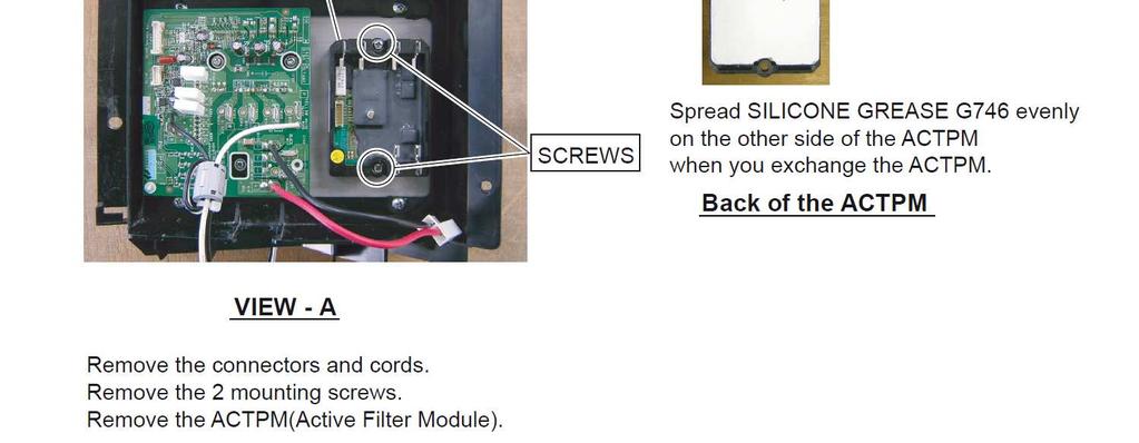
104 7.2.6 TRANSISTOR PCB and ACTPM PCB removal WO*A100LDT 104 Maintenance Document


105 7.2.7 FAN MOTOR removal WO*A100LDT RIGHT PANEL removal Maintenance Document


106 7.2.9 THERMISTOR removal HEAT EXCHANGER THERMISTOR EEV THERMISTOR WO*A100LDT OUTDOOR THERMISTOR 106 Maintenance Document


107 SOLENOID COIL removal 4 WAY VALVE EEV COIL removal PRESSURE SENSOR removal > Warning! < Wear gloves to prevent the frostbite, because a small amount of refrigerant leaks during work. WO*A100LDT Maintenance Document

 and 3Way valve (liquid) 4 Collect the refrigerant from the 3Way valve.")
108 COMPRESSOR removal Precautions for exchange of compressor. Do not allow moisture or debris to get inside refrigerant pipes during work. Procedure for compressor removal. 1 Turn off the power 2 Remove the SERVICE PANEL and RIGHT PANEL. 3 Fully close the 3Way valve (gas) and 3Way valve (liquid) 4 Collect the refrigerant from the 3Way valve. Start the following work after completely collecting the refrigerant. Do not reuse the refrigerant that has been collected. WO*A100LDT 108 Maintenance Document


109 WO*A100LDT Keep their shape better. There is a possibility of catching fire to oil when removing by the welding without cutting it. Procedure for compressor installation Reverse procedure to removing the compressor. Precautions for installation of compressor. 1 When brazing, do not apply the flame to the terminal. 2 When brazing, be sure to replace the air in the pipe with nitrogen gas to prevent forming oxidization scale. Maintenance Document
Part 3 Troubleshooting
 Part Troubleshooting What is in this part? This part contains the following chapters: Chapter See page Troubleshooting 2 Error Codes: Hydro-box 7 Error Codes: Outdoor Units Error Codes: System Malfunctions
R410A. WALL MOUNTEDtype INVERTER SPLIT TYPE ROOM AIR CONDITIONER. Models Indoor unit Outdoor unit AOYG07LEC AOYG09LEC AOYG12LEC AOYG14LEC
 SERVICE INSTRUCTION SPLIT TYPE ROOM AIR CONDITIONER WALL MOUNTEDtype INVERTER Models Indoor unit Outdoor unit ASYG07LECA ASYG09LECA ASYG12LECA ASYG14LECA AOYG07LEC AOYG09LEC AOYG12LEC AOYG14LEC R410A CONTENTS
R410A. WALL MOUNTEDtype INVERTER SPLIT TYPE ROOM AIR CONDITIONER. Models Indoor unit Outdoor unit AO*G09LTCN AO*G12LTCN AO*G14LTCN
 SERVICE INSTRUCTION SPLIT TYPE ROOM AIR CONDITIONER WALL MOUNTEDtype INVERTER Models Indoor unit Outdoor unit AS*G09LTCB AS*GLTCB AS*G4LTCB AO*G09LTCN AO*GLTCN AO*G4LTCN R40A CONTENTS. DESCRIPTION OF EACH
SERVICE INSTRUCTION R410A. WALL MOUNTEDtype INVERTER SPLIT TYPE ROOM AIR CONDITIONER. Models Indoor unit Outdoor unit AOU9RLS2H AOU12RLS2H AOU15RLS2H
 SERVICE INSTRUCTION SPLIT TYPE ROOM AIR CONDITIONER WALL MOUNTEDtype INVERTER Models Indoor unit Outdoor unit ASU9RLS ASURLS ASU5RLS AOU9RLSH AOURLSH AOU5RLSH R40A CONTENTS. DESCRIPTION OF EACH CONTROL
SPLIT TYPE ROOM AIR CONDITIONER. WALL MOUNTEDtype INVERTER. Models Indoor unit Outdoor unit AOU 9RLFW1 AOU12RLFW1 ASU 9RLF1 ASU12RLF1 R410A
 SERVICE INSTRUCTION SPLIT TYPE ROOM AIR CONDITIONER WALL MOUNTEDtype INVERTER Models Indoor unit Outdoor unit ASU 9RLF ASURLF AOU 9RLFW AOURLFW R40A CONTENTS. DESCRIPTION OF EACH CONTROL OPERATION. COOLING
SERVICE INSTRUCTION R410A. WALL MOUNTEDtype INVERTER SPLIT TYPE ROOM AIR CONDITIONER. Models Indoor unit Outdoor unit AO*G24LFL AO*G24LFCC AO*G30LFT
 SERVICE INSTRUCTION SPLIT TYPE ROOM AIR CONDITIONER WALL MOUNTEDtype INVERTER Models Indoor unit Outdoor unit AS*G4LFCA AS*G4LFCC AS*G0LFCA AO*G4LFL AO*G4LFCC AO*G0LFT R40A CONTENTS. DESCRIPTION OF EACH
SERVICE INSTRUCTION R410A. WALL MOUNTEDtype SPLIT TYPE ROOM AIR CONDITIONER INVERTER. Models Indoor unit Outdoor unit AO* R09LECN AO* R12LECN
 SERVICE INSTRUCTION SPLIT TYPE ROOM AIR CONDITIONER WALL MOUNTEDtype INVERTER Models Indoor unit Outdoor unit AS* A09LEC AS* A12LEC AO* R09LECN AO* R12LECN R410A CONTENTS 1. DESCRIPTION OF EACH CONTROL
3.2 E1 Outdoor Unit PCB Abnormality E4 Actuation of Low Pressure Sensor E5 Compressor Motor Lock 3 52
 Error Codes: Outdoor Units Error Codes: Outdoor Units Part. What Is in This Chapter? Introduction Overview In the first stage of the troubleshooting sequence, it is important to correctly interpret the
SERVICE INSTRUCTION R410A. SPLIT TYPE ROOM AIR CONDITIONER Cassette type Duct type Ceiling type INVERTER AO* G45LETL AO* G54LETL
 SPLIT TYPE ROOM AIR CONDITIONER Cassette type Duct type Ceiling type INVERTER SERVICE INSTRUCTION Models Indoor unit AU* G45LRLA AR* G45LMLA AR* G45LHTA AB* G45LRTA Outdoor unit AO* G45LETL AO* G54LETL
Operation manual FR EN NL DE IT. intended for professionals and end users. To be saved for future consultation
 Document n 1408-1 ~ 11/02/2010 Control Box FR EN NL DE IT Operation manual intended for professionals and end users To be saved for future consultation Fujitsu General (Euro) GmbH Werftstrasse 20 40549
ASU18RLF ASU24RLF AOU18RLXFWH AOU24RLXFWH CONTENTS WALL MOUNTED TYPE ROOM AIR CONDITIONER FOR EXTRA LOW TEMP. DISTRICT
 WALL MOUNTED TYPE ROOM AIR CONDITIONER FOR EXTRA LOW TEMP. DISTRICT Indoor unit ASU8RLF ASURLF Outdoor unit AOU8RLXFWH AOURLXFWH CONTENTS SPECIFICATIONS.................... DIMENSIONS........................
ASU18RLF ASU24RLF AOU18RLXFW1 AOU24RLXFW1 SPLIT TYPE ROOM AIR CONDITIONER WALL MOUNTED TYPE CONTENTS
 SPLIT TYPE ROOM AIR CONDITIONER WALL MOUNTED TYPE Indoor unit ASU8RLF ASURLF Outdoor unit AOU8RLXFW AOURLXFW CONTENTS SPECIFICATIONS.................... DIMENSIONS........................ REFRIGERANT SYSTEM
E11 Indoor Board Failed to Receive Signal from Signal Output Board III - 65 E12 Automatic Address Setting is in Progress: Automatic Address Setting
 E Indoor Board Failed to Receive Signal from Signal Output Board III - 65 E2 Automatic Address Setting is in Progress: Automatic Address Setting Start is Prohibited III - 66 E3 Indoor Unit Failed to Send
Part 5. Troubleshooting. 1. Normal Air Conditioner Phenomenon Air Conditioner Protection in Common
 Part 5 1. Normal Air Conditioner Phenomenon... 1611 2. Air Conditioner Protection in Common... 1611 3. Malfunction Code and... 162 160 1. Normal Air Conditioner Phenomenon 1.1 When outdoor unit appears
SERVICE MANUAL MUZ-DM25VA - E1, ER1, ET1 MUZ-DM35VA - E1, ER1, ET1 OUTDOOR UNIT. No. OBH751. Models HFC R410A
 OUTDOOR UNIT SERVICE MANUAL HFC utilized R410A. Models MUZ-DM25VA - E1, ER1, ET1 MUZ-DM35VA - E1, ER1, ET1 Indoor unit service manual MSZ-DM VA Series (OBH750) CONTENTS 1. TECHNICAL CHANGES 2 2. PART NAMES
Unit Controller (UC8) Quick Reference Operation and Fault Diagnosis
 Quick Reference Operation and Fault Diagnosis") Unit Controller (UC8) Quick Reference Operation and Fault Diagnosis (To be read in conjunction with labels TZ243 (Air-to-Air) & TZ245 (Water-to-Air) Date: 20 October 2015 Issue: 1 Index 1. Introduction...
Unit Controller (UC8) Quick Reference Operation and Fault Diagnosis (To be read in conjunction with labels TZ243 (Air-to-Air) & TZ245 (Water-to-Air) Date: 20 October 2015 Issue: 1 Index 1. Introduction...
DOMESTIC HOT WATER Follow operational sequence
 DOMESTIC HOT WATER Follow operational sequence Turn Winter/Summer selector to Summer position. The display is switch on. Go to section A Error 110 flashing Error 131 flashing Turn the selector to reset
CEILING type (60Hz) SPLIT TYPE ROOM AIR CONDITIONER CONTENTS. Models
 SPLIT TYPE ROOM AIR CONDITIONER CONTENTS. Models") SPLIT TYPE ROOM AIR CONDITIONER CEILING type (60Hz) Models Indoor unit ABU6RSLX Outdoor unit AOU6RLX CONTENTS SPECIFICATIONS....................... OUTLINE AND DIMENSIONS............. REFRIGERANT SYSTEM
SPLIT TYPE ROOM AIR CONDITIONER CEILING type (60Hz) Models Indoor unit ABU6RSLX Outdoor unit AOU6RLX CONTENTS SPECIFICATIONS....................... OUTLINE AND DIMENSIONS............. REFRIGERANT SYSTEM
Table of Contents. Service Procedures. Service Procedures. Measuring Superheat (4) Measuring Subcooling (5) Airflow Calculation (6-8)
 Measuring Subcooling (5) Airflow Calculation (6-8)") Table of Contents Refrigeration Cycle Service Procedures Measuring Superheat (4) Measuring Subcooling (5) Airflow Calculation (6-8) Solving Problems Identifying Low System Charge (9-11) Identifying High
Table of Contents Refrigeration Cycle Service Procedures Measuring Superheat (4) Measuring Subcooling (5) Airflow Calculation (6-8) Solving Problems Identifying Low System Charge (9-11) Identifying High
Troubleshooting & Reference
 Troubleshooting & Reference Error Code Descriptions Description of Error Codes - 9, 12 MBH code malfunction Error Display Repair Method 1 Storage slug (EEPROM) 2 Indoor PCB malfunction 3 Anti-freezing
VAL6 EPX. Maintenance Manual
 VAL6 EPX Maintenance Manual 1 Names of components 2 Specifications Burner Control for EP6JA Wiring Diagram 0.75gal/60 H for H lot 0.85gal/60 H 3 Wiring Diagram 4 Sequence Time Chart Plug IN Switch ON Ignition
SPLIT TYPE ROOM AIR CONDITIONER CEILING TYPE (60Hz)
") SPLIT TYPE ROOM AIR CONDITIONER CEILING TYPE (60Hz) Indoor unit MS6YF Outdoor unit MR6YF CONTENTS SPECIFICATIONS... OUTLINE AND DIMENSIONS... REFRIGERANT SYSTEM DIAGRAM.... CIRCUIT DIAGRAM... INDOOR PCB
SPLIT TYPE ROOM AIR CONDITIONER CEILING TYPE (60Hz) Indoor unit MS6YF Outdoor unit MR6YF CONTENTS SPECIFICATIONS... OUTLINE AND DIMENSIONS... REFRIGERANT SYSTEM DIAGRAM.... CIRCUIT DIAGRAM... INDOOR PCB
DESIGN & TECHNICAL MANUAL
 DTW_3SP001E_03 DESIGN & TECHNICAL MANUAL High power series ( 3 phase type ) FUTURE SOLUTION OF DOMESTIC HEATING Air to Water Split type 111OUTDOOR UNIT CONTENTS 3 PHASE TYPE : WO K112LAT, WO K140LAT, WO
SERVICE MANUAL 42QHF009DS* 42QHF012DS* 42QHF018DS* 42QHF022DS* 38QUS009DS* 38QUS012DS* 38QUS018DS* 38QUS022DS* Indoor unit.
 SERVICE MANUAL Indoor unit Outdoor unit 42QHF009DS* 42QHF012DS* 42QHF018DS* 42QHF022DS* 38QUS009DS* 38QUS012DS* 38QUS018DS* 38QUS022DS* INDEX PART1 GENERAL INFORMATION PART2 ELECTRICAL DIAGRAM PART3 TROUBLE
NO. 15FD-742 ISSUED: AUG. 10, 2007 REVISED: SEP. 30, 2013 HOSHIZAKI SELF-CONTAINED CRESCENT CUBER KM-30A KM-35A KM-50A KM-75A MODEL SERVICE MANUAL
 NO. 15FD-742 ISSUED: AUG. 10, 2007 REVISED: SEP. 30, 2013 HOSHIZAKI SELF-CONTAINED CRESCENT CUBER MODEL KM-30A KM-35A KM-50A KM-75A SERVICE MANUAL CONTENTS PAGE I. SPECIFICATIONS--------------------------------------------------------------------------------------1
ERROR CODES R22 & R407C Units Black = All Units Red = 4, 5, 6 & 7 Series Blue = 8 Series Green = KX / KX2 / KXR
 ERROR CODES R22 & R407C Units Black = All Units Red = 4, 5, 6 & 7 Series Blue = 8 Series Green = KX / KX2 / KXR Receiver Unit [if applicable] Error Code No indication Check Indications Indoor Circuit Board
TECH SHEET DO NOT DISCARD PAGE 1. If unsuccessful entry into diagnostic mode, actions can be taken for specific indications:
 TECH SHEET DO NOT DISCARD PAGE 1 WARNING Electrical Shock Hazard Disconnect power before servicing. Replace all parts and panels before operating. Failure to do so can result in death or electrical shock.
An occurrence of an Error will make a sound of error melody for 5sec and continuously show one of the Error Displays from the following errors.
 4. Troubleshooting 4-1. Error items and diagnostic codes An occurrence of an Error will make a sound of error melody for 5sec and continuously show one of the Error Displays from the following errors.
π H-6621 INDUSTRIAL DEHUMIDIFIER WARNINGS SPECIFICATIONS uline.com WATER REMOVAL ELECTRICAL REQUIREMENTS BUILT-IN ELECTRICAL SAFETY
 π H-6621 INDUSTRIAL DEHUMIDIFIER 1-800-295-5510 uline.com WARNINGS Plug into a grounded 3 prong outlet. Do not remove ground prong. Do not use an adapter. Do not use an extension cord if possible. Failure
SERVICE MANUAL MUZ-HC25VA - E1 MUZ-HC35VA - E1 MUZ-HC35VA - E2 MUZ-HC35VAB - E1 MUZ-HC35VAB - E2 OUTDOOR UNIT. No. OBH467.
 SPLIT-TYPE AIR CONDITIONERS Revision B: MUZ-HC35VA- E2 and MUZ-HC35VAB- E2 have been added. Please void OBH467 REVISED EDITION-A. OUTDOOR UNIT SERVICE MANUAL HFC utilized R410A. OBH467 REVISED EDITION-B
IMPORTANT. HOSHIZAKI provides this manual primarily to assist qualified service technicians in the service and maintenance of the icemaker.
 73105 IMPORTANT Only qualified service technicians should attempt to service or maintain this icemaker. No service or maintenance should be undertaken until the technician has thoroughly read this Service
TROUBLESHOOTING TROUBLESHOOTING. Indoor unit EEPROM parameter error. Indoor / outdoor units communication error. Zero-crossing signal detection error
 www.olmo-comfort.com TROUBLESHOOTING When below list for identification of error code occurs, please turn off air conditioner and disconnect power, and then contact the qualified professionals for service.
HT V2 HT Split
 Scroll compressor Refrigerant R07C Aqu@Scop HT V Aqu@Scop HT Split High Temperature Air-to-Water Heat Pumps Models -, -7 and 8-9.0 to 7.9kW Aqu@Scop HT V / Aqu@Scop HT Split Installation examples - Single
Warning: 230V / 1ph / 50Hz V / 3ph / 50Hz. Remarks: Make sure that you have enough power. (See page 15 Cable table)
") 1 2 Warning: - Do not place your hand or any other objects into the air outlet and fan. It could damage the heat pump and cause injuries; - In case of any abnormality with the heat pump, cut off the power
1 2 Warning: - Do not place your hand or any other objects into the air outlet and fan. It could damage the heat pump and cause injuries; - In case of any abnormality with the heat pump, cut off the power
Heat Pump Defrost Board Replacement Kit
 Bard Manufacturing Company, Inc. Bryan, Ohio 43506 8620-223 Heat Pump Defrost Board Replacement Kit KIT FEATURES This kit is made up of the current defrost control board 8201-129 and a new defrost sensor.
The breaker trips at once when it is set to ON. The breaker trips in few minutes when it is set to ON.
 Trip of breaker or The breaker trips at once when it is set to O. Measure insulation resistance to ground to see if there is any leakage. Air conditioner can not start up blow of fuse The air conditioner
Service Manual. DCXXXX, DEXXXX Model Compressor Refrigerators MODELS DC0040(K), DC0051(K) DE0040, DE0051 DE0240T, DE0251T DC0740(X), DE0740(X)
, DC0051(K) DE0040, DE0051 DE0240T, DE0251T DC0740(X), DE0740(X)") Service Manual DCXXXX, DEXXXX Model Refrigerators MODELS DC0040(K), DC0051(K) DE0040, DE0051 DE0240T, DE0251T DC0740(X), DE0740(X) DC0751(X), DE0751(X) Please note that the "X" at the end of certain model
Service Manual DCXXXX, DEXXXX Model Refrigerators MODELS DC0040(K), DC0051(K) DE0040, DE0051 DE0240T, DE0251T DC0740(X), DE0740(X) DC0751(X), DE0751(X) Please note that the "X" at the end of certain model
SERVICE MANUAL MUZ-FH25VE MUZ-FH35VE MUZ-FH50VE OUTDOOR UNIT. No. OBH624. Models HFC. Revision A: MUZ-FH50VE- E1 has been added. Please void OBH624.
 SPLIT-TYPE AIR CONDITIONERS Revision A: MUZ-FH50VE- E1 has been added. Please void OBH624. OUTDOOR UNIT SERVICE MANUAL HFC utilized R410A. OBH624 REVISED EDITION-A Models MUZ-FH25VE MUZ-FH35VE MUZ-FH50VE
SERVICE MANUAL K LIGHT COMMERCIAL
 SERVICE MANUAL 36 48 60K LIGHT COMMERCIAL Cassette indoor unit Under-ceiling indoor unit Ducted indoor unit 42QTD036DS* 42QTD048DS* 42QTD060DS* 42QZL036DS* 42QZL048DS* 42QZL060DS* 42QSM036DS* 42QSM048DS*
SERVICE MANUAL CLASSIC 10 SERIAL NUMBER FROM FEBRUARY 2011 (0211) TO PRESENT. DocID: 00G00089E
 TO PRESENT. DocID: 00G00089E") SERVICE MANUAL CLASSIC 10 SERIAL NUMBER FROM FEBRUARY 2011 (0211) TO PRESENT DocID: 00G00089E 2012 DENSO SALES CALIFORNIA, INC. All rights reserved. This book may not be reproduced or copied, in whole
SERVICE MANUAL CLASSIC 10 SERIAL NUMBER FROM FEBRUARY 2011 (0211) TO PRESENT DocID: 00G00089E 2012 DENSO SALES CALIFORNIA, INC. All rights reserved. This book may not be reproduced or copied, in whole
RTC-M_A series FTC-M_A series
 NO. T069-838 ISSUED: MAY 31, 2011 REVISED: JUN. 16, 2014 HOSHIZAKI UNDERCOUNTER REFRIGERATOR/FREEZER MODEL RTC-M_A series FTC-M_A series SERVICE MANUAL CONTENTS PAGE I. GENERAL INFORMATION---------------------------------------------------------------------------1
SERVICE MANUAL MUZ-D30NA MUZ-D30NA- U1 MUZ-D36NA MUZ-D36NA- U1 MUY-D30NA MUY-D36NA OUTDOOR UNIT. No. OBH502. Wireless type Models HFC R410A
 OUTDOOR UNIT SERVICE MANUAL HFC utilized R410A. OBH502 Wireless type Models MUZ-D30NA MUZ-D30NA- U1 MUZ-D36NA MUZ-D36NA- U1 MUY-D30NA MUY-D36NA Indoor unit service manual MSZ-D NA Series (OBH501) MSY-D
Aprilaire Dehumidifier Troubleshooting Manual Models 1830, 1850, 1870
 Aprilaire Dehumidifier Troubleshooting Manual Models 1830, 1850, 1870 Table of Contents Troubleshooting Diagnostic Codes... 2 E1... 2 E2, E3... 3 E4.4 E5, E6... 7 E7, E8... 8 E9.9 Verifying Capacity...
Aprilaire Dehumidifier Troubleshooting Manual Models 1830 & 1850
 Aprilaire Dehumidifier Troubleshooting Manual Models 1830 & 1850 Table of Contents Troubleshooting Diagnostic Codes... 2 E1, E2... 2 E3, E4... 3 E5, E6 & E7... 7 E8... 8 E9 9 Verifying Capacity... 10 Water
KM-630MAH KM-630MWH KM-630MRH
 NO.: ISSUED: 73114 JUNE 23, 2004 HOSHIZAKI MODULAR CRESCENT CUBER MODEL KM-630MAH KM-630MWH KM-630MRH SERVICE MANUAL IMPORTANT Only qualified service technicians should attempt to service or maintain this
Freightliner Refrigerator Troubleshooting Guide For (TJ18F) (TJ22F) (TJ18FP3)
 (TJ22F) (TJ18FP3)") www.dometic.com Freightliner Refrigerator Troubleshooting Guide For Before initiating troubleshooting, the following equipment is recommended: Multimeter, 20 gauge (min) wires to use as jumpers, and 12Vdc
www.dometic.com Freightliner Refrigerator Troubleshooting Guide For Before initiating troubleshooting, the following equipment is recommended: Multimeter, 20 gauge (min) wires to use as jumpers, and 12Vdc
Simple Self-Diagnosis by Malfunction Code
 Detail Division 0 Indoor Unit System Others A C E F H J L P U M 7 8 9 External device activated (unified) Protection devices activated (unified) of Miswiring of Shortage of amount ( unit) Shortage of External
TECHNICAL DATA & SERVICE MANUAL MTF94C5TAA
 TECHNICAL DATA & SERVICE MANUAL MTF94C5TAA 0.8180.472.0 07/2005 Page 1. SPECIFICATIONS 3 1-1 Unit Specifications 3 1-2 Major Component Specifications 4 2. DIMENSIONAL DATA 6 2-1 Unit Dimensions 6 3. ELECTRICAL
SERVICE MANUAL MUZ-GB50VA - E1 MUZ-GB50VA - E2 MUZ-GB50VA - E3 OUTDOOR UNIT. No. OB455. Wireless type Models HFC. Revision E: REVISED EDITION-E R410A
 Revision E: MUZ-GB50VA- E3 has been added. Please void OB455 REVISED EDITION-D. OUTDOOR UNIT SERVICE MANUAL HFC utilized R410A. OB455 REVISED EDITION-E Wireless type Models MUZ-GB50VA - E1 MUZ-GB50VA -
Reliability is a beautiful thing TM MODULAR CRESCENT CUBER KM-500MAH KM-500MWH KM-500MRH SERVICE MANUAL
 Reliability is a beautiful thing TM MODULAR CRESCENT CUBER KM-500MAH KM-500MWH KM-500MRH SERVICE MANUAL NUMBER: 73104 ISSUED: NOV. 7, 2002 REVISED: DEC. 16, 2003 IMPORTANT Only qualified service technicians
Trouble Shooting Guide PWA, 3-phase (D10571)
") Trouble Shooting Guide PWA, 3-phase (D10571) Trouble Shooting Guide Problem Possible Cause Possible Remedy Unit does not start Unit does not cool No power to unit, breaker tripped Low voltage Loose wire
Trouble Shooting Guide PWA, 3-phase (D10571) Trouble Shooting Guide Problem Possible Cause Possible Remedy Unit does not start Unit does not cool No power to unit, breaker tripped Low voltage Loose wire
Trouble Shooting Guide FAA, 3-phase (D3631)
") Trouble Shooting Guide FAA, 3-phase (D3631) Trouble Shooting Guide Problem Possible Cause Possible Remedy Unit does not start Unit does not cool No power to unit, breaker tripped Low voltage tripped Loose
Trouble Shooting Guide FAA, 3-phase (D3631) Trouble Shooting Guide Problem Possible Cause Possible Remedy Unit does not start Unit does not cool No power to unit, breaker tripped Low voltage tripped Loose
SERVICE MANUAL CLASSIC PLUS 14 SERIAL NUMBER FROM JANUARY 2008 (0108) TO PRESENT. DocID: 00G00019E
 TO PRESENT. DocID: 00G00019E") SERVICE MANUAL CLASSIC PLUS 14 SERIAL NUMBER FROM JANUARY 2008 (0108) TO PRESENT DocID: 00G00019E 2008 DENSO SALES CALIFORNIA, INC. All rights reserved. This book may not be reproduced or copied, in whole
SERVICE MANUAL CLASSIC PLUS 14 SERIAL NUMBER FROM JANUARY 2008 (0108) TO PRESENT DocID: 00G00019E 2008 DENSO SALES CALIFORNIA, INC. All rights reserved. This book may not be reproduced or copied, in whole
KML F SERIES KML H SERIES
 NO.: ISSUED: REVISED: 73085 AUG. 18, 1999 JAN. 13, 2004 HOSHIZAKI MODULAR CRESCENT CUBER MODELS KML F SERIES KML H SERIES SERVICE MANUAL IMPORTANT Only qualified service technicians should attempt to service
Servicing manual. Wall-mounted condensing gas boiler 600 Series - 11S / 19S / 24S / 24C /2002 GB(EN) For trade use
 For trade use") GB122 7210 1300-12/2002 GB(EN) For trade use Servicing manual Wall-mounted condensing gas boiler 600 Series - 11S / 19S / 24S / 24C Please read thoroughly before attempting to diagnose fault List of contents
GB122 7210 1300-12/2002 GB(EN) For trade use Servicing manual Wall-mounted condensing gas boiler 600 Series - 11S / 19S / 24S / 24C Please read thoroughly before attempting to diagnose fault List of contents
SERVICE MANUAL ROOM AIR CONDITIONER TAN/TAG-A28FWIS TAN/TAG-A32FWIS CONTENTS
 SERVICE MANUAL ROOM AIR CONDITIONER TAN/TAG-A28FWIS TAN/TAG-A32FWIS CONTENTS SPECIFICATION... 1 FUNCTIONS... 5 SERVICE FUNCTION EXPLANATION... 7 OPERATION DETAILS... 8 TROUBLESHOOTING GUIDE... 13 PERFORMANCE
7-5. Remove the Grille to Install the Indoor Unit
 7-5. Remove the Grille to Install the Indoor Unit Basically, these models can be installed and wired without removing the grille. If access to any internal part is needed, follow the steps as given below.
MAINTENANCE & TROUBLESHOOTING GUIDE LEAK ALARM CHANNEL DRY OIL WATER AUX ALARM HIGH LOW CRITICAL WATER TANK LEVEL ALARM MODEL LDE-740 ADVANCE PAPER
 PNEUMERCATOR Liquid Level Control Systems Electronic Systems Excluding LC2000 And TMS Series MAINTENANCE & TROUBLESHOOTING GUIDE 400 300 500 FUEL LEVEL LEAK MONITOR 1 200 600 OIL/GAS NORMAL WATER PNEUMERCATOR
Waterbath Repair and Troubleshooting
 Waterbath Repair and Troubleshooting Description # Text Box Explanation 1 Begin Water Bath Testing 2 Does the machine power up? 3 Is power reaching the control board? Start the diagnostic process for a
SERVICING S-15 CHECKING CAPACITOR
 S-15 CHECKING CAPACITOR The direct drive motors are of the permanent split capacitor design. A run capacitor is wired across the auxiliary and a portion of the main windings. The capacitors primary function
HOSHIZAKI MODULAR CRESCENT CUBER MODEL KM-280MAH KM-280MWH SERVICE MANUAL
 NO. 73117 ISSUED: AUG. 15, 2004 REVISED: HOSHIZAKI MODULAR CRESCENT CUBER MODEL KM-280MAH KM-280MWH SERVICE MANUAL IMPORTANT Only qualified service technicians should attempt to service or maintain this
SERVICE MANUAL MUFZ-KJ50VE - E1, E2, ER1, ER2, ET1, ET2 MUFZ-KJ35VE OUTDOOR UNIT. No. OBH667. Models HFC
 Revision D: MUFZ-KJ25VE - E2, ER2, ET2, MUFZ- KJ35VE - E2, ER2, ET2 and MUFZ- KJ50VE - E2, ER2, ET2 have been added. Please void OBH667 REVISED EDITION-C. OUTDOOR UNIT SERVICE MANUAL HFC utilized R410A.
SERVICE MANUAL CLASSIC PLUS 26 SERIAL NUMBER FROM JANUARY 2009 (0109) TO PRESENT. DocID: 00G00025E
 TO PRESENT. DocID: 00G00025E") SERVICE MANUAL CLASSIC PLUS 26 SERIAL NUMBER FROM JANUARY 2009 (0109) TO PRESENT DocID: 00G00025E 2009 DENSO SALES CALIFORNIA, INC. All rights reserved. This book may not be reproduced or copied, in whole
SERVICE MANUAL CLASSIC PLUS 26 SERIAL NUMBER FROM JANUARY 2009 (0109) TO PRESENT DocID: 00G00025E 2009 DENSO SALES CALIFORNIA, INC. All rights reserved. This book may not be reproduced or copied, in whole
(PD[ $LU 'U\HU 5 ( ) 5, * ( 5 $ 7 ( ' 7 < 3 ( & ( 6 6 ( ' $, 5 ' 5 < ( 5 6 ('5&) ದ ('5&) Instructions Manual
 5, * ( 5 $ 7 ( ' 7 < 3 ( & ( 6 6 ( ' $, 5 ' 5 < ( 5 6 ('5&) ದ ('5&) Instructions Manual") Instructions Manual 1. Important safety notes - Please read... 1 1.1. Transportation... 1 1.2 Positioning... 1 1.3 Installation... 1 1.4 Before operating... 1 1.5 Maintenance by an engineer... 1 1.6 Maintenance
Instructions Manual 1. Important safety notes - Please read... 1 1.1. Transportation... 1 1.2 Positioning... 1 1.3 Installation... 1 1.4 Before operating... 1 1.5 Maintenance by an engineer... 1 1.6 Maintenance
! WARNING To avoid risk of electrical shock, personal injury or death; disconnect power to dryer before servicing, unless testing requires power.
 27 Domestic Dryer Technical Information MDE6700A*, MDG6700A* Due to possibility of personal injury or property damage, always contact an authorized technician for servicing or repair of this unit. Refer
SERVICE MANUAL MUZ-GB50VA - E1 MUZ-GB50VA - E2 MUZ-GB50VA - E3 OUTDOOR UNIT. No. OB455. Models HFC
 Revision G: Errors in TROUBLESHOOTING have been corrected. Please void OB455 REVISED EDITION-F. OUTDOOR UNIT SERVICE MANUAL HFC utilized R410A. OB455 REVISED EDITION-G Models MUZ-GB50VA - E1 MUZ-GB50VA
HRE-MA series HFE-MA series HRFE-MA series
 NO. R262-841 ISSUED: MAY. 31, 2011 REVISED: APR. 30, 2014 HOSHIZAKI COMMERCIAL REFRIGERATOR/FREEZER MODEL HRE-MA series HFE-MA series HRFE-MA series SERVICE MANUAL CONTENTS PAGE I. GENERAL INFORMATION---------------------------------------------------------------------------1
Henny Penny Blast Chiller/Freezer Models BCC/BCR-140 Models BCC/BCR-175 Models BFR/BCR-350
 Henny Penny Blast Chiller/Freezer Models BCC/BCR-140 Models BCC/BCR-175 Models BFR/BCR-350 TECHNICAL MANUAL Section TABLE OF CONTENTS Page Section 1. TROUBLESHOOTING... 1-1 1-1. Introduction... 1-1 1-2.
Quickheat 30 weather compensated boiler control
 Quickheat 0 weather compensated boiler control A compact and sophisticated heating controller The compact KM controller is designed for the control of fan assisted boilers with modulating burners. The
Samsung EHS Heat Pump Test
 Samsung EHS Heat Pump Test The following questionnaire is designed for installers who have experience with heat pumps, are currently MCS accredited, and who want to fast track their Samsung accreditation
Guide To Troubleshooting INEFFICIENT COOLING FANS
 Guide To Troubleshooting INEFFICIENT COOLING FANS TABLE OF CONTENTS Introduction Enclosure Cooling Basics Key Attributes of Enclosure Cooling Symptoms of Poor Enclosure Cooling Typical Cooling Fan Problems
QUICK TEST MODE: SERVICE MODE: Fast Track Troubleshooting. Bulletins: WITH POWER OFF - PRESS: Spin + Soil + POWER. **Test Mode** With the Power Off
 Fast Track Troubleshooting Model: WF56H9100 Bulletins: IMPORTANT SAFETY NOTICE For Technicians Only This service data sheet is intended for use by persons having electrical, electronic, and mechanical
SERVICE MANUAL MUZ-D30NA / - MUZ-D36NA / - MUY-D30NA / - MUY-D36NA / - OUTDOOR UNIT. No. OBH502. Models HFC. Revision E: REVISED EDITION-E R410A
 Revision E: Capacity corrections have been corrected [7-1. 2), 3)]. OBH502 REVISED EDITION-D is void. OUTDOOR UNIT SERVICE MANUAL HFC utilized R410A. OBH502 REVISED EDITION-E Models MUZ-D30NA / - 1 / -
Q - Series Boiler. Troubleshooting Manual
 Q - Series Boiler Troubleshooting Manual WARNING There are a number of live tests that are required when fault finding this product. Extreme care should be used at all times to avoid contact with energized
TECHNICAL & SERVICE MANUAL. Ceiling Concealed
 STAND BY DEFROST CHECK CLOCK ON OFF NOT AVAILABLE FILTER CHECK MODE TEST RUN FUNCTION SPLIT-TYPE, HEAT PUMP AIR CONDITIONERS TECHNICAL & SERVICE MANUAL Series SEZ Ceiling Concealed R40A.OC0 REVISED EDITION-A
Servicing manual. 600 Series - 11S / 19S / 24S / 24C. Wall-mounted condensing gas boiler. For trade use
 GB122 Servicing manual Wall-mounted condensing gas boiler 600 Series - 11S / 19S / 24S / 24C For trade use Please read thoroughly before attemting to diagnose fault 7217 4900 (03/2010) GB/IE List of contents
NZ 400 AUTOMATIC FIRE ALARM SYSTEM OPERATORS MANUAL
 NZ 400 AUTOMATIC FIRE ALARM SYSTEM OPERATORS MANUAL Document No...G108WO1.DOC Serial No... Issue Date...17 th SEPTEMBER 1999 Software Version...1.4 APPROVED TO: NZS 4512:1997 AS/NZS 3548:1992 Fire Alarm
OWNER S MANUAL. R 410A Ductless Split System Air Conditioner and Heat Pump
 R 410A Ductless Split System Air Conditioner and Heat Pump Models DLC4(A/H) Outdoor Unit, DLF4(A/H) Indoor Unit Sizes 9K, 12K, 18K, 24K, 30K and 36K Please read the operating instructions and safety precautions
AUXG18LRLB AUXG24LRLB UTG-UKYA-W AOYG18LBCA AOYG24LBCA. SPLIT TYPE AIR CONDITIONER CASSETTE TYPE (50Hz) CONTENTS
 CONTENTS") SPLIT TYPE AIR CONDITIONER CASSETTE TYPE (50Hz) Indoor unit AUXG8LRL AUXGLRL UTG-UKYA-W Outdoor unit AOYG8LCA AOYGLCA CONTENTS SPECIFICATIONS.................... DIMENSIONS....................... REFRIGERANT
SPLIT TYPE AIR CONDITIONER CASSETTE TYPE (50Hz) Indoor unit AUXG8LRL AUXGLRL UTG-UKYA-W Outdoor unit AOYG8LCA AOYGLCA CONTENTS SPECIFICATIONS.................... DIMENSIONS....................... REFRIGERANT
Product Information and Technical Guide
 Product Information and Technical Guide Side by Side and Top Mount Refrigerators January 2005 - June 2005 White-Westinghouse 5995449906 October 2005 TABLE OF CONTENTS Safe Servicing Practices ------------------------------------------------------------------------------------------
NUMBER: ISSUED: JULY 13, /336 73/23 STACKABLE CRESCENT CUBER KM-1300SWH-E SERVICE MANUAL FOR QUALIFIED SERVICE PERSON HOSHIZAKI
 89/336 73/23 NUMBER: 73141 ISSUED: JULY 13, 2006 STACKABLE CRESCENT CUBER KM-1300SWH-E SERVICE MANUAL FOR QUALIFIED SERVICE PERSON HOSHIZAKI IMPORTANT Only qualified service technicians should attempt
OWNER S MANUAL. Vintage Signature Series models: AC750, AC1050, AC1100, AC1250, AC1500, AC1750. Proudly Made in the USA.
 OWNER S MANUAL Vintage Signature Series models: AC750, AC1050, AC1100, AC1250, AC1500, AC1750 Proudly Made in the USA support@aquacomfort.com 888-475-7443 Manufacturing High Quality, High Efficiency Heat
Product Information and Technical Guide
 Product Information and Technical Guide Side by Side and Top Mount Refrigerators July 2003 - December 2003 White-Westinghouse 5995540384 January 2004 TABLE OF CONTENTS Safe Servicing Practices ------------------------------------------------------------------------------------------
DC INVERTER MULTI-SYSTEM AIR CONDITIONER Capacity 7,500BTU / h 9,000BTU / h 11,900BTU / h 17,500BTU / h 24,200BTU / h
 AIR CONDITIONER AIR CONDITIONER TECHNICAL & SERVICE MANUAL INDOOR UNIT : CS-MKS7NKU CS-MKS9NKU CS-MKS12NKU CS-MKS18NKU CS-MKS24NKU DC INVERTER MULTI-SYSTEM AIR CONDITIONER Capacity 7,500BTU / h 9,000BTU
EBAC MODEL CD30 INDUSTRIAL DEHUMIDIFIER OWNER S MANUAL
 EBAC MODEL CD30 INDUSTRIAL DEHUMIDIFIER OWNER S MANUAL Ebac Industrial Products 704 Middle Ground Boulevard Newport News, VA 23606 Tel: 757 873 6800 Fax: 757 873 3632 Website: www.ebacusa.com UNPACKING
Service Manual CAUTION ! WARNING SAFETY CONSIDERATIONS INTRODUCTION. 38MA*R Outdoor Unit Single Zone Ductless System Sizes 09 to 36
 38MA*R Outdoor Unit Single Zone Ductless System Sizes 09 to 36 Service Manual TABLE OF CONTENTS PAGE SAFETY CONSIDERATIONS... 1 INTRODUCTION... 1 MODEL / SERIAL NUMBER NOMENCLATURES... 2 SPECIFICATIONS...
Hoffman Controls 759-ECM. Installation & Operating Instructions. Introduction. Installation. Pre-Installation Information/ Instruction
 Hoffman Controls Installation & Operating Instructions Introduction CAUTION Failure to read and understand the accompanying instructions and diagrams prior to energizing the Controller may result in permanent
INSTRUCTION MANUAL T119 1MN0110 REV. 0. operates with ISO9001 certified quality system
 INSTRUCTION MANUAL 1MN0110 REV. 0 operates with ISO9001 certified quality system TECSYSTEM S.r.l. 20094 Corsico (MI) Tel.: +39-024581861 Fax: +39-0248600783 http://www.tecsystem.it R. 1.1 25/08/16 ENGLISH
NO. F ISSUED: JUN. 18, 2008 REVISED: JUN. 17, 2011 HOSHIZAKI SELF-CONTAINED CRESCENT CUBER KM-100A KM-125A MODEL SERVICE MANUAL
 NO. F003-756 ISSUED: JUN. 18, 2008 REVISED: JUN. 17, 2011 HOSHIZAKI SELF-CTAINED CRESCENT CUBER MODEL KM-100A KM-125A SERVICE MANUAL IMPORTANT This manual should be read carefully before the icemaker is
Hoshizaki America, Inc.
 Hoshizaki America, Inc. Commercial Refrigerators & Freezers Models RR28A RR55A RF28A RF55A A Superior Degree of Reliability SERVICE MANUAL www.hoshizaki.com Number: 73139 Issued: 8-31-2006 IMPORTANT Only
Keeps Flashing. Keeps Flashing. Flashes Twice. Keeps Flashing. Keeps Flashing. Stays Off. Keeps Flashing. Stays Off. Keeps Flashing.
 ERROR CODES R410A Black = All R410A Red = FD Split 1, 2 Series R410A Blue = KX4 & KXR4 Series R410A (does not cover SRK & SCM MODELS) Error Code Indoor Circuit Board Red LED Green LED Outdoor Circuit Board
EBAC MODEL CD425 ( ) INDUSTRIAL DEHUMIDIFIER OWNER S MANUAL
 INDUSTRIAL DEHUMIDIFIER OWNER S MANUAL") EBAC MODEL CD425 (1018110) INDUSTRIAL DEHUMIDIFIER OWNER S MANUAL Ebac Industrial Products 704 Middle Ground Boulevard Newport News, VA 23606 Tel: 757 873 6800 Fax: 757 873 3632 Website: www.ebacusa.com
EBAC MODEL CD425 (1018110) INDUSTRIAL DEHUMIDIFIER OWNER S MANUAL Ebac Industrial Products 704 Middle Ground Boulevard Newport News, VA 23606 Tel: 757 873 6800 Fax: 757 873 3632 Website: www.ebacusa.com
SERVICE MANUAL FOR QUALIFIED SERVICE PERSON HOSHIZAKI 89/336 73/23 SELF-CONTAINED CRESCENT CUBER KM-150BAF-E KM-150BWF-E
 89/336 73/23 NUMBER: 73108 ISSUED: APRIL 19, 2000 REVISED: JAN. 13, 2004 SELF-CONTAINED CRESCENT CUBER KM-150BAF-E KM-150BWF-E SERVICE MANUAL FOR QUALIFIED SERVICE PERSON HOSHIZAKI IMPORTANT Only qualified
Polar Air Dryer. Instructions Manual PDRCF PDRCF R E F R I G E R A T E D T Y P E C O M P R E S S E D A I R D R Y E R S
 Polar Air Dryer R E F R I G E R A T E D T Y P E C O M P R E S S E D A I R D R Y E R S PDRCF1150029 PDRCF4602000 Instructions Manual TABLE OF CONTENTS 1. Important safety notes - Please read... 1 1.1. Transportation...
SERVICE MANUAL 15SF. DocID: 00G00092E
 SERVICE MANUAL 15SF DocID: 00G00092E 2014 DENSO AUTOMOTIVE SYSTEMS AUSTRALIA PTY. LTD. All rights reserved. This book may not be reproduced or copied, in whole or in part, without the written permission
KSIM20912-H216 KSIM30912-H216 KSIM40912-H216
 SERVICE MANUAL KLIMAIRE AIRCONDITIONER KSIM DC INVERTER MULTI TYPE KSIM20912-H216 KSIM30912-H216 KSIM40912-H216 DC MULTI OUTDOOR UNITS CONTENTS 1. General information of Outdoor Units...3 2 Features...4
AXIAL HEATER TROUBLE SHOOTING GUIDE. Models: AX24 N/PV, AX24 N/PV LT, AX24 LP AX26 N/PV, AX26 N/PV LT, AX26 LP AX28 N/PV, AX28 N/PV NT, AX28 LP
 AXIAL HEATER TROUBLE SHOOTING GUIDE Page 1 July 2009 Table of Contents Frequently Asked Questions... 3 Axial Heater CONTROL (Siemens LME69) Troubleshooting Chart... 4 Axial Heater BURNER Troubleshooting
Trouble Shooting Guide RAA, 1-phase (D3627)
") Trouble Shooting Guide RAA, 1-phase (D3627) Trouble Shooting Guide Problem Possible Cause Possible Remedy Unit does not start Unit does not cool No power to unit, breaker tripped Low voltage tripped Loose
Trouble Shooting Guide RAA, 1-phase (D3627) Trouble Shooting Guide Problem Possible Cause Possible Remedy Unit does not start Unit does not cool No power to unit, breaker tripped Low voltage tripped Loose
Trouble Shooting Guide PAA, 1-phase (D3731)
") Trouble Shooting Guide PAA, 1-phase (D3731) Trouble Shooting Guide Problem Possible Cause Possible Remedy Unit does not start Unit does not cool No power to unit, breaker tripped Low voltage tripped Loose
Trouble Shooting Guide PAA, 1-phase (D3731) Trouble Shooting Guide Problem Possible Cause Possible Remedy Unit does not start Unit does not cool No power to unit, breaker tripped Low voltage tripped Loose
SERVICE MANUAL OFFICE PRO 36 SERIAL NUMBER FROM DECEMBER 2004 (1204) TO MARCH 2007 (0307)
 TO MARCH 2007 (0307)") SERVICE MANUAL OFFICE PRO 36 SERIAL NUMBER FROM DECEMBER 2004 (1204) TO MARCH 2007 (0307) 2008 DENSO SALES CALIFORNIA, INC. All rights reserved. This book may not be reproduced or copied, in whole or in
SERVICE MANUAL OFFICE PRO 36 SERIAL NUMBER FROM DECEMBER 2004 (1204) TO MARCH 2007 (0307) 2008 DENSO SALES CALIFORNIA, INC. All rights reserved. This book may not be reproduced or copied, in whole or in