WASHER TRAINING WM2277. Rel WM2277 Washer Training
|
|
|
- Rose Harper
- 5 years ago
- Views:
Transcription

1 WASHER TRAINING WM Rel

2 SAFETY FIRST! Use the right tool for the job! 2
3 No Solicitation LG Electronics in no way supports, condones or will tolerate the solicitation of personnel while in attendance to this, or any LG event. Furthermore, there will be no communication of salary, benefits or job descriptions in general. Anyone found to be part of any such communication will immediately be dismissed from this class, and will not be allowed to attend future events. LG supplies this training class for the benefit of all in attendance, we ask your assistance in keeping this a professional meeting and to remain focused only on the technical improvement and education of our service network. 3
4 SAFETY NOTICE The information in this training manual is intended for use by persons possessing an adequate background in electrical equipment, electronic devices, and mechanical systems. In any attempt to repair a major appliance, personal injury and property damage can result. The manufacturer or seller maintains no liability for the interpretation of this information, nor can it assume any liability in conjunction with its use. When servicing this product, under no circumstances should the original design be modified or altered without permission from LG Electronics. Unauthorized modifications will not only void the warranty, but may lead to property damage or user injury. If wires, screws, clips, straps, nuts, or washers used to complete a ground path are removed for service, they must be returned to their original positions and properly fastened. 4 T-1
5 CAUTION To avoid personal injury, disconnect the power before servicing this product. If electrical power is required for diagnosis or test purposes, disconnect the power immediately after performing the necessary checks. Also be aware that many household appliances present a weight hazard. At least two people should be involved in the installation or servicing of such devices. Failure to consider the weight of an appliance could result in physical injury. 5 T-1
6 ESD WARNING Some of the electronics in appliances are electrostatic discharge (ESD) sensitive. ESD can weaken or damage the electronics in these appliances in a manner that renders them inoperative or reduces the time until their next failure. Connect an ESD wrist strap to a ground connection point or unpainted metal in the appliance. Alternatively, you can touch your finger repeatedly to a ground connection point or unpainted metal in the appliance. Before removing a replacement part from its package, touch the anti-static bag to a ground connection point or unpainted metal in the appliance. Handle the electronic control assembly by its edges only. When repackaging a failed electronic control assembly in an anti-static bag, observe these same precautions. 6 T-1
7 REGULATOR INFORMATION This equipment has been tested and found to comply with the limits for a Class B digital device, pursuant to Part 15 of the FCC Rules. These limits are designed to provide reasonable protection against harmful interference when the equipment is operated in a residential installation. This equipment generates, uses, and can radiate radio frequency energy, and, if not installed and used in accordance with the instruction manual, may cause harmful interference to radio communications. However, there is no guarantee that interference will not occur in a particular installation. If this equipment does cause harmful interference to radio or television reception, which can be determined by turning the equipment off and on, the user is encouraged to try to correct the interference by one or more of the following measures: Reorient or relocate the receiving antenna; Increase the separation between the equipment and the receiver; Connect the equipment to an outlet on a different circuit than that to which the receiver is connected; or consult the dealer or an experienced radio/tv technician for help. 7 T-1
8 DISCLAIMER The information in this training manual was accurate at the time of publication. Every effort has been made to ensure accuracy. Updates, changes, etc. are available via GCSC and LGCSAcademy. 8 T-1

9 COMPLIANCE The responsible party for this device s compliance is: LG Electronics Alabama, Inc. 201 James Record Road Huntsville, AL, T-1
10 INTRODUCTION The WM2277** washer is most notable in that there are two distinct versions with this same model number. The only way to tell them apart is by date code, which is included in the serial number. (See page 7 concerning serial numbers.) Models with a date code of 608 or later are the newer model (without the recirculation pump); models beginning with 607 or earlier are the older models (with the recirculation pump). The later series includes three added options: TubClean, SpinSense, and Water+Plus. The recirculating pump has been eliminated and the pump housing changed accordingly. As a result, there have been changes in the display board and assembly, the main control board, the flat cable, the owner s manual, and the tub size. 10 T-4
11 SPECIFICATIONS Color Power Input Weight Electric Power Consumption Drum Speed Options Cycles Wash/Rinse temperatures Options Item Washing Drain Motor Water Heater Wash Spin 120 V AC, 60 H Z 190 lbs (86 kg) 280 W 80 W 1000 W 42 rpm 0 ~ 1150 rpm Prewash, Stain cycle, Extra Rinse, Rinse+Spin, Delay wash, Water Plus 7 5 WM2277H* W White, B Black, S Titanium Prewash, Stain cycle, extra rinse, Rinse+Spin, Delay Wash, Water+Plus Full chart included in training manual. 11 T-4
12 FEATURES LARGE CAPACITY The larger drum (3.83 cu. ft. I.E.C.) allows washing of larger (heavier) loads and oversized items (comforters, curtains, blankets, etc.) There is less wrinkling and tangling of the laundry. DIRECT DRIVE The brushless DC motor drives the drum directly without belts, pulleys, or transmissions. The maximum spin speed of 1,150 RPM extracts more water from the laundry, reducing drying times. TILTED DRUM and LARGE DOOR The tilted drum (10 ) and large door opening allow easier loading and unloading. 12 T-5
13 FEATURES ROLLER JETS and BALLS The baffles pick up water as the drum turns and allow it to pour through the clothing as it tumbles. The balls enhance the washing performance while maintaining fabric care. AUTOMATIC LOAD DETECTION The microprocessor reads the current required to turn the drum and determines the weight of the load. This input is used to make numerous decisions during the wash cycle. 13 T-5

14 MAIN TITLE BUILT-IN HEATER The internal heater helps maintain the water at its optimal temperature for selected cycles. The SANITARY cycle kills most common germs and bacteria. CHILD LOCK This allows the user to lock the controls. Children then cannot play with the buttons and disturb the wash cycle. 14 T-6
15 HE DETERGENT USE ONLY HE DETERGENT (HIGH EFFICIENCY) Use only HE detergents. These machines need no more than 2 tablespoons of powdered or 1 ounce of liquid detergent for a load. Overuse of laundry products will reduce efficiency and cause buildup and odors in the machine. Use fabric softener sparingly. We suggest no more than 2 teaspoons per load. Be careful when using the Ultra or X-tra concentrated brands, because very thick or highly viscous liquids do not dispense properly. You might need to use a different product or dilute your preferred product before putting it into the dispenser. Remember, these machines use small amounts of water, so you need small amounts of detergent, softener, and bleach. 15 T-6
16 SERIAL NUMBER The serial number is unique to each product. It gives information concerning the time and place of manufacture. The serial number is required to be paid for warranty service and to get the correct part in the event a running production change was made. Some models may have four (4) letters instead of two (2) for the product code number. The third and fourth letters are significant only to the manufacturing facility. 16 T-7
17 SERIAL NUMBER Eventually, serial numbers will all be migrated to this new format, which includes a sequential production number, model code, date code, and other information. 17 T-7
18 FUZZY LOGIC To get the best washing performance, the user selects one of the standard cycles. Sensors in the washer allow the microprocessor to make an infinitely variable number of adjustments as the cycle progresses. Adjustments are made automatically for load size, incoming water temperature, soil level, rinses required, and other variables. 18 T-8
19 DOOR LOCK The door has an automatic, electrically operated lock system. When the machine is off or paused, the door can be opened by pulling it. When the machine is operating, the electric latch keeps the door closed. The door cannot be opened: When the washer is operating When the power failed or the washer is unplugged (until the capacitor discharges and releases the lock) When the DOOR LOCK light is on When the drum is still turning 19 T-8
20 DOOR LOCK LAMP The DOOR LOCK lamp lights: When the washer is operating When the water level sensor frequency is lower than 22.9 khz When the temperature inside the tub is over 45 C (113 F) 20 T-8
21 WATER CIRCULATION On earlier versions of the WM2277, the recirculation pump circulates the water during most of the cycle. Later versions do not include the recirculation pump. During the WASH cycle, the pump runs continuously for the first 3 minutes and then intermittently throughout the cycle. During the RINSE cycle, it runs continuously as soon as the appropriate amount of rinse water has been added. This recirculated water enters the drum at the top of the door at a small shower head. This spray not only keeps the window and gasket clean, it allows the clothes to be soaked with detergent or rinse water more quickly and can be used to control an oversudsing event. 21 T-9
 and filter are located at the bottom left front corner. The filter can be unscrewed, cleaned, and replaced. Earlier versions include a recirculation pump; later versions do not.")
22 WATER CIRCULATION The recirculation pump is separate from the drain pump, but they are attached to opposite sides of the filter housing. The pump(s) and filter are located at the bottom left front corner. The filter can be unscrewed, cleaned, and replaced. Earlier versions include a recirculation pump; later versions do not. Use the small drain hose to evacuate the water remaining in the bottom of the tub before removing the filter. 22 T-9


23 WATER CIRCULATION The drain pump is on the left and exhausts the water via the gray corrugated hose. Older versions of the 2277 have a recirculating pump on the right, which recirculates water from the tub to the shower spray at the top of the door gasket via the smaller black hose. Newer versions do not have the recirculating pump. 23 T-9
24 PARTS IDENTIFICATION FRONT 24 T-10
25 PARTS IDENTIFICATION - REAR The air vent on the back of the machine must be left open and clear at all times. If the washer is installed in a closet or closed laundry alcove, there must be sufficient clearance and ventilation. The closet should have a full louvered door with at least 800 square inches (0.5 m 2 ) of open area for ventilation. The washer requires a space of at least 1 inch (2.5 cm) between the wall and the machine on each side and at least 4 inches (10 cm) between the back of the washer and the wall. Additional space may be needed for servicing. 25 T-10~11
26 ACCESSORIES The washer comes with the two input hoses. The blue stripe is for cold water and the red stripe is for hot water. The hoses are NOT mechanically identical; it is critical to the performance of the washer to have the hot and cold hoses connected correctly. The wrench is used to remove (and replace) the shipping bolts and to adjust the leveling feet. Be sure to leave it and encourage the customer to retain the wrench, the four shipping bolts, and the manual in a safe place in the event the washer requires service or the customer moves. 26 T-11

27 SHIPPING BOLTS The shipping bolts MUST BE REMOVED before operating the washer. Use the wrench supplied or a socket wrench for speed. Notice there is a piece of tape securing the cord and reminding the installer to remove the bolts before connecting the cord. There is also a clip on one of the bolts to prevent connection before the bolts are removed. 27 T-11

28 INSTALLATION Unpack the washer near the installation area. Cut the straps and lift off the box. Check the packing materials for manuals and accessories before discarding them. Notice the wrench packed in the foam shipping base. This will be used to level the legs and to remove the shipping bolts. 28 T-12

29 INSTALLATION Be sure to remove the foam block from the base of the washer. Don t throw the wrench away with the packaging. 29 T-12


30 INSTALLATION Remove the shipping bolts when you get the washer into the utility room and not before. Save the bolts in case the washer must be moved for servicing or relocation. 30 T-13

31 INSTALLATION Notice that one of the bolts has a retainer clip for securing the cord. This is another way to encourage the removal of the shipping bolts. 31 T-13

32 INSTALLATION The power cord is taped to the back of the machine with a sticker reminding the installer or customer to remove the shipping bolts before installing or using the washer. It is imperative that these bolts be removed; if they remain in place, serious damage will result when the washer is operated. 32 T-13
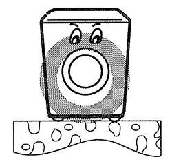
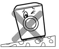
33 INSTALLATION INSTALL THE WASHER ON A FIRM, FLAT SURFACE. 33 T-14

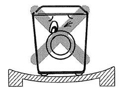
34 INSTALLATION ADJUST THE FEET TO BE LEVEL. 34 T-14

35 INSTALLATION This photo shows the leveling leg with plastic foot and locking ring. After adjusting the foot by using the wrench to raise or lower it. You can lock the adjustment into place by tightening the lock ring against the underside of the washer. 35 T-14

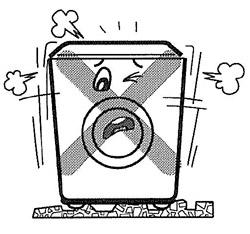
36 INSTALLATION Use a spirit level to adjust the feet to make the washer level. You may have to adjust more than one foot to get the desired results. The legs must be firmly against the floor, and the washer must be level in all directions: front to back, left to right, and corner to corner. Proper leveling will minimize shaking and vibration. 36 T-14

37 INSTALLATION - PEDESTAL This procedure covers installing and leveling the 7½ and 13 pedestals for 27 washers, dryers, and combos. If the products are stacked, the washer must be below the dryer, and you ll use only one pedestal. 37 T-15
38 INSTALLATION - PEDESTAL 1. Remove the pedestal, installation hardware, and instructions form the shipping carton. Set the pedestal as close to the installation position as possible. 2. Level the pedestal on a flat, solid floor before proceeding. Lock down the rear adjusters but leave the front ones free for now. 38 T-15


39 INSTALLATION - PEDESTAL 3. Note which holes are for the washer and which are for the dryer. If you are stacking the appliances, the washer must be on the bottom. 39 T-15
40 INSTALLATION - PEDESTAL 4. Remove the protective paper from the adhesive surface of the bracket. Be particularly careful, because when the adhesive makes contact, there is no adjustment possible. 40 T-15

41 INSTALLATION - PEDESTAL 5. Depending upon the model, your pedestal may have straight or curved brackets. The curved ones are to be used on the rear positions when mounting a dryer to a pedestal, but can also be used in any other position on the pedestal. 41 T-15
42 INSTALLATION - PEDESTAL 6. Holding the exposed adhesive away from the appliance, insert the screws and get them started. Then press the brackets to the appliance and tighten all the screws. Rub the bracket from side to side to ensure a complete bond
43 INSTALLATION - PEDESTAL 7. Use the wrench to turn each leg of the appliance approximately ¼ turn to put a little pressure between the appliance and the pedestal. This will eliminate any rattles. 8. If you are stacking the dryer on top of the washer, it is usually easier to set the pedestal and washer into place and connect the water and drain hoses before placing the dryer on top 43 T-16

44 CONNECTION - WATER Be sure the rubber washer is inside the hose end. Attach the hoses to the washer (RED is HOT, BLUE is COLD). Tighten them firmly but don t strip the plastic threads on the washer connections. Be sure to use the correct hoses for HOT and COLD. The hoses may look mechanically identical, but the HOT hose is marked with a RED stripe and can withstand higher temperatures and pressures. 44 T-17
45 CONNECTION - DRAIN The drain pipe should be firmly attached to the standpipe or the laundry tub or sink where it drains. The pump has sufficient power to cause the pipe to move around when the water is expelled. The pump can lift the drain water a maximum of 96 inches (2.4 m), but there is no minimum height requirement. The vacuum breaker in the drain line will prevent drainage by gravity or siphoning. The hose can lay flat into a floor drain as long as the end of it is not submerged. 45 T-17
46 CONNECTION - ELECTRICAL The washer requires a 120 VAC, 60 Hz., dedicated, 15-amp circuit. 46 T-17

47 CONTROL PANEL The control panel is located on the front of the washer. All options are available from the control panel. 47 T-18

48 CONTROL PANEL Option Buttons 48 T-19
49 OPTION CHART MAX. WATER TEMP SPIN SPEED Extra Hot Hot Warm Cold 158 F 122 F 104 F 77 F Extra High 1,150 High 980 Normal 960 Low 600 SOIL LEVEL - adds time to wash and spin cycles STAIN CYCLE - adds time and changes wash/rinse temperature 49 T-19
50 CONTROL PANEL Press DELAY WASH and SOIL LEVEL to read the drum RPM. Press DELAY WASH and PRE WASH to read the water temperature in Celsius. Press DELAY WASH and BEEPER to read the water level frequency. 50 T-19

51 CONTROL PANEL 51 T-20
52 CYCLE CHART 52 T-21
53 BEFORE PERFORMING SERVICE Be careful to avoid electric shock when disconnecting parts for troubleshooting. Most terminals in the washer have 120 VAC or VDC on them, sometimes even when the washer is off. Spinning the drum by hand, even when the washer is OFF and unplugged, can cause the motor to generate voltage and backfeed it into the controls. 53 T-21
54 DISPENSER The dispenser drawer is a multi-chambered reservoir that allows the user to add all the appropriate laundry additives before starting the cycle. It has a place for pre-wash detergent, main wash detergent, fabric softener, and bleach. Powdered or liquid detergents may be used, but softener and bleach must be liquids. Detergents must carry the HE designation. Do not use regular detergents in the washer or oversudsing will occur. We recommend using NO MORE THAN 2 TABLESPOONS of powdered HE detergent or NO MORE THAN 1½ OUNCES of liquid HE detergent. 54 T-22

55 DISPENSER TOP VIEW 55 T-22

56 DISPENSER WATER PATHWAYS 56 T-22
57 DISPENSER Notice that the pre-wash and main wash fill tubes enter the dispenser at an angle. If one or the other fill valve is opened, the water goes into the appropriate detergent compartment. However, if they are opened simultaneously, the streams deflect and dispense the softener. Some water may run through the main and pre-wash compartments, but since the detergent has already been dispensed in an earlier part of the cycle, this is of no consequence. 57 T-22
58 DISPENSER If liquid detergent is added to the pre-wash box, it will run immediately into the tub. This does not affect the operation of the cycle. To use liquid detergent in the main wash, place the detergent siphon box in the main wash compartment. Otherwise, the main wash liquid detergent will run into the tub along with the pre-wash detergent, causing oversudsing in the prewash and no cleaning in the main wash. 58 T-23

59 DISPENSER SIPHON BOX 59 T-23
60 DISPENSER The siphon boxes are designed to hold a liquid laundry product until the appropriate time for dispensing into the load. When the box fills with water, it begins to discharge its contents into the washer fill stream. Once the siphon action has started, it will continue until the siphon box has emptied itself. Use only regular viscosity bleaches and softeners; the ultra versions are usually much thicker and do not dispense well, if at all. By the end of any cycle, water will have run through all of the dispenser compartments, preventing any cross-contamination of subsequent loads. The MAX indicator shows the maximum you can put in the dispenser cup before siphoning begins, NOT the maximum you should use per load. 60 T-23


61 MOTOR The motor is a direct-drive, brushless, DC motor. It is attached to the drum via a splined shaft, eliminating belts, pulleys, transmissions, and the inherent problems associated with them. The rotor is attached to the shaft by one large (17 mm) bolt. Remove the bolt by holding the drum and turning. 61 T-24

62 MOTOR When the rotor is removed, you can remove the stator. Loosen the six bolts holding it to the tub and lift it away. Be careful of the wiring. You must remove a connector that powers the stator and another that connects to the hall sensor. When reassembling the motor, these connectors must be reassembled before the stator is mounted. 62 T-24
63 MOTOR The DC motor can be driven from stopped to maximum speed in infinite steps in either direction. There are 36 poles on the stator; 12 permanent magnets spaced around the rotor. There are no brushes to wear out. Unlike a more traditional brushless motor, the rotor surrounds the stator rather than being attached to it. A Hall Effect sensor determines the speed and direction of the motor. It also can read that the load is off balance when the drum speed fluctuates. 63 T-24

64 MOTOR 64 T-25
65 HALL EFFECT SENSOR The Hall Effect sensor is easily removed and replaced. You ll have to remove the rotor and stator to access the sensor. When replacing the rotor, you ll probably need a helper to hold the drum in place when you push the rotor onto the shaft. Otherwise, the drum may move forward enough to make replacing the bolt difficult. The helper can also hold the drum from turning while you tighten the bolt. 65 T-25

66 HALL SENSOR Before going to this trouble, check the connector on the main board. The motor connector is the red one closest to the heat sink. Pull the connector off and verify the board is receiving a signal from the sensor. A test procedure is included in the training manual and will be discussed later. 66 T-25
 Gray is (-) Red is Hb Blue is Ha.")
67 HALL SENSOR Check the wiring diagram for your machine. The correct wiring terminal colors are: White is (+) Gray is (-) Red is Hb Blue is Ha. The correct depiction is shown left and the incorrect depiction is shown right. 67 T-26
68 HALL SENSOR Hall Sensor testing methods are now available on the following pages when LE error code troubleshooting says hall sensor is out of order or defective. Test FIRST!! 68 T-27
69 HALL SENSOR Terminal Designation / Ohm & Voltage Specifications Magnetic Pickups & Attaching Clips 1 BL (Ha) 2 RD (Hb) 3 Not Used 4 GRY (-) 5 WH (+) OHM Checking Voltage Checking 5 to 1 = 10KΏ 5 to 4 = 10 to 15 Vdc Voltage Input 5 to 2 = 10KΏ 4 to 1 = pulsing 10 Vdc Signal Output 4 to 2 = pulsing 10 Vdc Signal Output Note: Ohm values are approximate; if the ohm check determines either resistor open, hall sensor has failed and must be replaced!! 69 T-27

70 HALL SENSOR Part No. 6501KW2002A 70 T-28
71 HALL SENSOR Hall Sensor Testing The hall sensor can be tested from the control board or at the hall sensor. Ohm Testing the Hall Sensor If tested off the stator using the diagram on the previous page, ohm check the resistors from pin 5 to pin 1 and pin 2. If the hall sensor is good, you should measure approximately 10 KΩ from pin 5 to pin 1 and 10 KΩ from pin 5 to pin 2. If either test shows an open (infinity) the hall sensor is defective and must be replaced. 71 T-28
72 HALL SENSOR Voltage Testing Hall Sensor at Stator If measuring voltage from the control board to the hall sensor, follow the following steps: 1. Unplug the power cord. 2. Remove the rear washer panel. 3. Locate the Hall sensor connector on the stator behind the rotor. 4. Place the meter leads on terminals 5 to 4, white to gray. 5. Plug in the power cord, close the door, and press the power button. DO NOT PRESS START! 72 T-28
73 HALL SENSOR 6. You should measure 10 to 15 Vdc. If 10 to 15 Vdc is present, the control board is OK! If not, follow the testing output voltages on control board in next section. 7. To measure output signal voltage from the hall sensor, carefully move test leads to terminals 4 (gray) to 1 (blue). Slowly rotate the motor rotor by hand. You should read a pulsing 10 Vdc. If 10Vdc is measured from 4 to 1, move the lead on the blue wire to the red wire, terminal 2. Repeat rotating motor rotor by hand. You should read a pulsing 10 Vdc. 73 T-28
74 HALL SENSOR 8. If pulsing 10 Vdc is measured from pin 4 to pin 1 and pin 4 to pin 2, the hall sensor is OK! If either test netted only 9 to 10 Vdc without changing (no pulsing) the hall sensor is likely defective. Disconnect power by unplugging the washer. Ohm check the hall sensor as outlined in Ohm Testing Hall Sensor to verify failure of the hall sensor. 74 T-28


75 HALL SENSOR Control Board Testing Location 75 T-29
76 HALL SENSOR Control Board Output and Hall Sensor Input can be measured with the connector connected to the board and the machine operating. Also, these voltages can be measured by parking the meter leads on the desired terminals and spinning the tub briskly with the power cord disconnected. White to Gray 10 to 15 Vdc Gray to Blue pulsing 10 Vdc Gray to Red pulsing 10 Vdc Note: If 10 Vdc from gray-to-blue or gray-to-red does not change (pulse), that resistor is open! Confirm by disconnecting the power, disconnecting the hall sensor connector on the main board, and ohm check that individual circuit! 76 T-29
77 HALL SENSOR With power disconnected and the connector disconnected, the hall sensor can be tested ohmmetrically from: White to Blue 10 KΩ White to Red 10 KΩ Note: Ohm values are approximate; if either ohm check shows an open, the wire harness is open or the hall sensor is defective. Test both separately to determine the area of failure! 77 T-29


78 MAIN TITLE Actual Terminal Wiring The potting epoxy has been removed to show the PC board and components 78 T-30
79 HALL SENSOR Voltage Testing Hall Sensor at the Control Board 1. Unplug the power cord. 2. Remove the rear panel. 3. Remove the top plate. 4. Remove the main board from the rear cabinet corner. 5. Remove the main board cover, as shown on page Locate the hall sensor connector (white, 4-pin) using the wiring diagram and wire colors as your guide. 7. Plug in the power cord, close the door, and press POWER. 8. DO NOT PRESS START! 79 T-30
80 HALL SENSOR 9. Place your meter leads on the WHITE and GRAY wires. You should read 10 ~ 15 VDC output from the main board to the hall sensor. If 10 ~ 15 VDC are not observed, the main board is defective. 10. Place your meter leads on the BLUE and GRAY wires. Turn the motor rotor slowly by hand. You should measure a pulsing 10 VDC. Place your meter leads on the RED and GRAY wires. Turn the motor rotor slowly by hand. You should measure a pulsing 10 VDC If both of these tests measure a pulsing 10 VDC, the hall sensor and wiring harness are OK. If either or both tests measures 9 ~ 10 VDC but does not pulse or change, the hall sensor has failed and must be replaced. If either test measures 0 (zero) voltage, check the red and blue wires for continuity. Repair or replace the wiring harness as necessary. 80 T-30
81 TEST MODE 1. The washer must be empty and OFF to enter the test mode. Press and hold SPIN SPEED and SOIL LEVEL. 2. Press POWER. 3. Press START/PAUSE to cycle through the test modes. (See chart.) 81 T-31
82 TEST MODE # of times the START button is pressed Event All lamps on, door locked Tumble clockwise Low speed spin High speed spin Prewash inlet valve opens Main wash valve opens Hot inlet valve opens Bleach inlet valve opens Tumble clockwise Heater on for 3 seconds Circulation pump runs Drain pump runs Power off, unlock door Display XX:XX (see next slide) rpm (40~50) rpm rpm water level freq (25 ~ 65) water level freq (25 ~ 65) water level freq (25 ~ 65) water level freq (25 ~ 65) rpm (40~50) water temperature C water level freq (25 ~ 65)) water level freq (25 ~ 65) All lamps off 82 T-31
83 TEST MODE The EPROM check sum will be displayed at the beginning of the test. The checksum will indicate the model number and the program on the main board. 1F:61 WM2677H*M 83 T-31
84 WATER LEVEL FREQUENCY Press DELAY WASH and BEEPER simultaneously. The display will indicate the water level frequency. Multiply by 0.1 to get the frequency in kilohertz. For example, a reading of 255 would be multiplied by 0.1 to get 25.5 as the frequency. 84 T-31
85 ERROR DISPLAY If you press START/PAUSE when an error is displayed, any error (except PE) will disappear and the machine will enter PAUSE mode. In the event of PE, te, or de, The power will be turned off within 20 seconds and the error code will blink. In the event of any other error code, the power will be turned off after 4 minutes. If the error code is FE, the power will NOT be turned off. 85 T-32
86 ERROR DISPLAY 86 T-32
87 ERROR DISPLAY 87 T-33
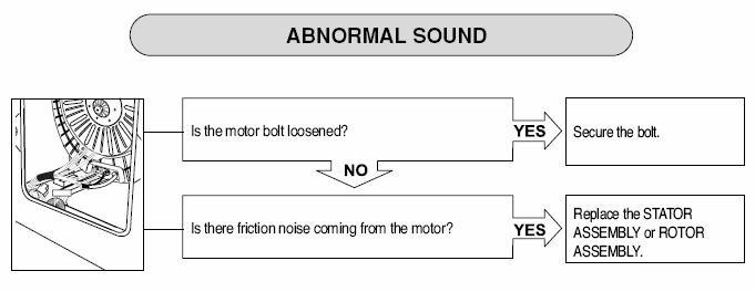
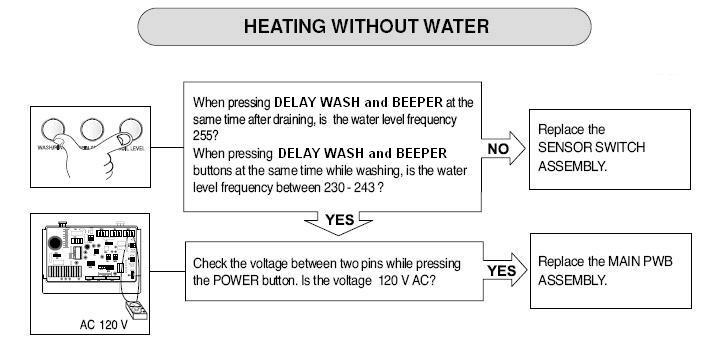
88 DIAGNOSIS These diagnostic troubleshooting trees are particularly useful when speaking to the customer by phone. You can step him through the chart and often discern the issue before making a service call. This makes it easier to take the right parts and fix the product on only one call. 88 T-34
89 DIAGNOSIS 89 T-35
90 DIAGNOSIS 90 T-36
91 TROUBLESHOOTING 91 T-37
92 TROUBLESHOOTING 92 T-38
93 TROUBLESHOOTING NO WATER SUPPLY 93 T-39
94 TROUBLESHOOTING DETERGENT NOT DISPENSED 94 T-39
95 TROUBLESHOOTING SOFTENER/BLEACH NOT DISPENSED 95 T-40
96 TROUBLESHOOTING 96 T-40
97 TROUBLESHOOTING 97 T-41
98 TROUBLESHOOTING 98 T-41
99 TROUBLESHOOTING 99 T-42

100 TROUBLESHOOTING HEATER MALFUNCTION (CONTINUOUS OVERHEATING) 100 T-42
101 TROUBLESHOOTING Before conducting this diagnostic procedure, be sure your version includes the recirculation pump. The pump housings are not interchangeable, and this option cannot be added to a version not so equipped at the factory. 101 T-43
102 TROUBLESHOOTING 102 T-44
103 DISASSEMBLY and REPAIR The following pages will show the instructions for disassembly, repair, replacement of parts, and reassembly. Many times, electrical components may be tested by connecting the appropriate meter to the leads or connectors on the main PC Board. (Refer to the block wiring diagram.) Proper diagnosis will eliminate unnecessary labor and expedite repairs. 103 T-45

104 BLOCK WIRING DIAGRAM 104 T-45
105 MAIN BOARD 105 T-45

106 DISASSEMBLY and REPAIR 1. Remove two screws on the back of the top plate. 2. Pull the top plate backward and lift, as shown. 3. Remove the detergent drawer. 4. Remove two screws behind the detergent drawer. 106 T-46


107 DISASSEMBLY and REPAIR 6. Remove one screw from the corner of the control panel. 7. Lift the top away from the support rail and pull the control panel up and away to remove. 8. Remove eight screws to separate the control panel and PWB. 9. Reassembly is the reverse of these steps. 107 T-46
108 DISASSEMBLY and REPAIR Often, you can diagnose a failed part by removing its connector on the main board and connecting the tester to the leads in the connector. 108 T-47

109 DISASSEMBLY and REPAIR MAIN BOARD 1. Disconnect the POWER connector and the Water Level Sensor Switch. 2. Remove the protective cover. Press the plastic tabs out of the way to remove the cover. The main board is potted, so no repairs are possible. Replacement is the only option. 109 T-47

110 DISASSEMBLY and REPAIR 3. Disconnect the connectors on the main board. They are all different, keyed, and colorcoded to prevent incorrect connection. 4. Pull the wires out of the way. 110 T-47

111 DISASSEMBLY and REPAIR 5. Remove one screw on the back of the washer to release the main board housing. 6. Remove the main board by sliding it to the right and lifting it up. Replacement is accomplished by pressing it toward the back of the washer and sliding it toward the left. 111 T-47

112 DISASSEMBLY and REPAIR DISPENSER 1. Remove the top plate. (See page 46.) 2. Remove the dispenser drawer. 3. Remove two screws to release the dispenser. 112 T-48
113 DISASSEMBLY and REPAIR 4. Loosen the clamp on the large hose that runs from the dispenser to the drum. Have an old towel handy to stuff under the dispenser to soak up any spillage. 113 T-48
 #2 White; white/black (main) #3 Blue; white/black (pre-wash) #4 Red; blue/black wires (hot) They should measure 120 VAC± 10% or 950~ 975 Ω with the harness")
114 DISASSEMBLY and REPAIR 5. Disconnect the connector from the solenoid. Make a note of the color codes and connections. #1 Blue; yellow/black (bleach) #2 White; white/black (main) #3 Blue; white/black (pre-wash) #4 Red; blue/black wires (hot) They should measure 120 VAC± 10% or 950~ 975 Ω with the harness disconnected. 6. Remove two screws from the back of the cabinet 114 T-48

115 DISASSEMBLY and REPAIR NOISE FILTER 1. Remove the connectors from the noise filter. 2. Remove the screw from the top bracket. 3. Replace the filter as an assembly. There are no userserviceable parts in it. The white connector is input; the pink is output. Both are 110 VAC. 115 T-48

116 DISASSEMBLY and REPAIR FRONT CABINET, TUB, and DRUM NOTE! There is a piece of adhesive foam tape along the top rail on both sides of the machine. This is to prevent noise from vibration. It may become stuck to the top, so you ll need to use an extra push to get the top plate loose. 116 T-49

117 DISASSEMBLY and REPAIR 1. Remove the top plate. 2. Remove the control panel. 3. Remove four screws that secure the front panel. 117 T-49

118 DISASSEMBLY and REPAIR 4. Remove the screw that secures the filter cover. Be sure to drain the water. 5. Use a flat screwdriver or a putty knife to loosen the filter cover and pull it out. 6. Stick the screwdriver into the cover slot and pry it out sideways to free it. 118 T-49

119 DISASSEMBLY and REPAIR 7. Open the door. 8. Remove the clamp using special tool 383EER4001A. Leave the gasket attached to the tub at this time. (The inner clamp requires another special tool, part 383ER4004A for removal and replacement.) 119 T-50
120 DISASSEMBLY and REPAIR 9. Lean the cabinet front forward, being careful to avoid breaking the glass. The door is HEAVY. 10. Disconnect the door switch connector. (Remember to replace it upon reassembly.) 11. Lift the door and front cover off the cabinet base as an assembly. Lay it face down on a blanket or some other protective surface. 120 T-50

121 DISASSEMBLY and REPAIR 12. Separate the spring retaining clip so you can lift the tub out of the cabinet. Be careful and make sure you have disconnected every wire and hose to avoid damage or complications. 121 T-50

122 DISASSEMBLY and REPAIR 13. Use the weights you removed from the front of the tub as supports to hold the tub while you work on it and to avoid damaging the shaft and floor. 122 T-51

123 DISASSEMBLY and REPAIR 14. Unbolt the tub halves to separate them and remove the drum. Be careful to avoid damaging the gasket between the halves or it must be replaced. Do not pry on the mating surfaces of the drum halves. 123 T-51
124 DISASSEMBLY and REPAIR Removing the door with the front cover still on the machine. 1. Open the door. 2. Remove seven screws from the hinge cover. 3. Pry off the hinge cover with a flat screwdriver. 4. Remove the screw at the bottom of the hinge. 5. Lift the door off the hinge. CAUTION! The door is HEAVY! 124 T-52

125 DISASSEMBLY and REPAIR 1. Open the door. 2. Remove the gasket clamp using special tool 383EER4001A. 3. Remove the two screws holding the switch. 4. Push the gasket aside to remove the switch. 5. Unplug the switch to change it. 6. Make sure the wires don t fall back in before you can replace the switch. 125 T-52

126 DISASSEMBLY and REPAIR 1. Remove the front cabinet. 2. Drain the water from the sump. 3. Remove the clamps and hoses. 4. Remove two screws and push the pump backward and up. 126 T-53

127 DISASSEMBLY and REPAIR 5. Press down the plastic tab on the base behind the pump to slide the pump assembly backward. You don t have to worry if you break the tab. It is there for the assembly process in the factory. A screw holds the pump housing in place when the washer is assembled. Just slide it into the bracket. 127 T-53

128 DISASSEMBLY and REPAIR 6. You can tilt the pump in either direction to remove/replace the individual pumps without having to remove the tub. Have a towel handy to catch the spillage. 128 T-53

129 DRAIN PUMP Before performing this operation, verify which version WM2277 you are repairing. Some do not have the recirculation pump. 129 T-54
130 DRAIN PUMP The drain pump and the circulating pump are attached to either side of the filter housing. The pumps are different and are not interchangeable. The drain pump is used to exhaust the water from the washer. The recirculating pump serves three purposes: it sprays water from the tub onto the laundry, creating a better saturation of detergent and better rinsing, it keeps the window clean, and it allows the customer to see water in the tub. The filter between the pumps is not a lint filter in the traditional since. It serves to trap larger objects (keys, coins, buttons, etc.) that may find their way into the washer and protects the pumps from physical damage. 130 T-54
131 DRAIN PUMP Depending upon which version you have, the washer may not have a circulating pump (the pump on the right) and the corresponding electrical and plumbing connections. The pump housings are very similar but not interchangeable, and the circulating pump cannot be added to models that are not so equipped at the factory. 131 T-54

132 DRAIN PUMP This photo shows the drain pump and pump housing for the models without the recirculating pump. The housings look very similar but are not interchangeable and cannot be modified to fit models that include the recirculation pump. 132 T-54
133 HEATER 1. Remove the front cabinet. 2. Drain the water from the sump. 3. Remove the push-on connectors from the heater. 4. Remove the nut that holds the ground wire. Then loosen but do not remove the nut that secures the heater clamp and pull the heater out. You may have to wiggle it to release the gasket. 133 T-55
 The heater runs on 120 VAC.")
134 HEATER The heater element must slide in to its bracket, which is attached to the rear half of the tub. Proper positioning is critical. (Note the drum half seam near the bottom of photo.) The heater runs on 120 VAC. Ohm check is 14 Ω 134 T-55

135 THERMISTOR 1. Remove the front cabinet. 2. Drain the water from the sump. 3. Unplug the white connector. 4. Hold the bracket and pull the thermistor out. The thermistor can be pulled out of the rubber grommet and replaced the same way, without removing the grommet from the tub. Be sure the bracket on the thermistor is snapped into place between the rubber tabs on the grommet. 135 T-55
136 REMOVAL OF FOREIGN OBJECTS 1. Remove the top cover. 2. Remove the front cabinet cover. 3. Remove the heater. 4. Fish out the foreign object(s) using a wire or bar. (See next slide.) 136 T-56
137 HEATER REMOVAL 137 T-56
138 DISASSEMBLY - MOTOR 1. Remove the back cover. 2. Remove the large bolt in the center shaft. (Your helper can hold the inside of the drum.) 3. Pull the rotor off the shaft. 138 T-57

139 DISASSEMBLY - MOTOR 4. Remove two screws from the tub bracket. 5. Remove six bolts on the stator. 6. Unplug two connectors on the stator. 7. Pull the stator off the shaft. 139 T-57

140 DISASSEMBLY - MOTOR 8. When re-installing, the clamps and the ground screw must be installed and the connectors pressed into place before the rotor is bolted onto the shaft. 140 T-57
 Be sure to press in the safety tab before pushing the pin out of the damper.")
141 DAMPER 1. Disconnect the dampers from the tub and the base. (See photos, left.) Be sure to press in the safety tab before pushing the pin out of the damper. You can use a socket to hold the tab in while you squeeze the pin with the special tool 383EER4003A. 141 T-58

142 DAMPER 2. The flat end of the tool goes on the small end and the split end allows the head end to pass through while the pin is pushed out. The color and/or appearance of the damper may vary by model. 142 T-58

143 DAMPER 3. Use special tool 383EER4003A to remove the damper pins. If you are replacing the dampers, you ll have to remove both ends. If you are removing the tub for major repair work, disconnect the damper ends at the base and leave the other ends connected until you remove the tub. When putting the tub back into the machine, connect the dampers to the tub first. It is much easier that way. 4. Be careful not to pull the dampers apart while they are disconnected. 143 T-58
144 WATER LEVEL SWITCH The water level detector switch monitors the water level and feeds this information to the MICOM. The sensor reads air pressure in an air chamber on the tub. The air pressure changes in relation to the depth of the water, moving a diaphragm in the switch. As the water level fluctuates, it raises or lowers the iron center in the coil, which, in turn, changes the electric resonance of the oscillator circuit of which it is a part. As water level decreases, frequency increases. (e.g. A low water level may read 25.5kHz, while a high water level might read 21.4 khz.) These readings are approximate; washers in the field may vary slightly from these figures. 144 T-59

145 WATER LEVEL SWITCH The pressure sensor (water level switch) is mounted on a bracket attached to the main board. Be sure to unplug the machine to service this component, because it is live even when the machine is off. 145 T-59
146 WATER LEVEL SWITCH Press DELAY WASH and BEEPER simultaneously. The display will indicate the water level frequency. Multiply by 0.1 to get the frequency in kilohertz. For example, a reading of 255 would be multiplied by 0.1 to get 25.5 as the frequency. 146 T-59

147 TIPS and TRICKS HOSES When replacing the large hoses, be sure to avoid getting the lip turned under the hose clamp. This will damage the hose and cause a leak. The large hoses have notches on the ends to index them on the connectors. Be sure the notch is pushed down all the way on the index boss. 147 T-60

148 TIPS and TRICKS BAFFLES (LIFTERS) You can replace the baffle and rollers without having to remove the drum. Unscrew the retaining screw at the back of the baffle. Slide it toward the front of the washer to remove it. You can unscrew the retainer inside the baffle to replace the roller balls. 148 T-60

149 TIPS and TRICKS MUSHROOM VALVE Be sure the mushroom is in place before attaching the hose. If the stem is too long, it will contact the drum and make significant noise when the drum turns. See the parts list for the correct part numbers for these valves. They are not shown on the exploded view. 149 T-60
150 TIPS and TRICKS BALL (Off Balance) SENSOR There isn t one. This function is handled by the microprocessor and the hall sensor. Photo not available 150 T-60

151 MAIN BOARD 151 T-61
152 TEST The main board must be replaced if defective; it is not repairable. This diagram is shown to point you to the various connectors that can be removed or used as test points. Testing at the connectors will allow the servicer to make a more complete diagnosis and eliminate some of the time required to disassemble and check various components. For example, the hall sensor can be tested by removing the connector at the main board and following the procedure on page 26 in the training manual. 152 T-61
 to run into a shallow pan.")
153 DRAINNG THE SUMP Pull out the little hose and remove the end cap. Allow the water (16 ~ 32 ounces) to run into a shallow pan. Do not pull the hose so far out it kinks or the water will not drain. Have a towel handy or leaks and spills. 153 T-61
154 EXPLODED VIEW Pages 62 ~ 64 in the training manual. 154 T-62~64
155 PARTS LIST This parts list is included with part numbers for the newer (Date Code 608 and later) version of WM2677. For part numbers for the earlier version, see the original service manual and the service bulletins included in this training manual. (Pages 65 ~ 68 in the traiing manual.) Loc # Part No Description *001 *002 *003 *004 A100 A101 A102 A ER3025L 3890EZ3524A 3W20018B 3828ER3027G ABJ ER1028A 4830ER3001A 4930ER3014A Owner s Manual Box Wrench (packed in base of shipping container) Service Manual Cabinet Assembly Cover, Rear Bushing, drain hose Holder, drain hose 155 T-65~68
156 SERVICE BULLETINS LG issues service bulletins as products are improved and for many other reasons. The bulletins available at the time this manual was printed are included. Updated materials, including this training manual, service manuals, owner s manuals, specifications, and other items are available online at LG s GCSC (Global Cyber Service Center) and via LGCSAcademy. We suggest you check for bulletins before servicing a product to get all the latest information. These bulletins are of particular significance in that they cross-reference parts that are used in one version or the other. For instance, control panel is different. Although it may appear identical, the options have changed. Similarly, the main board has changed to accommodate these options. The pump housing is different because the older version has a pump on each side and these pumps were not identical. The newer version has no recirculation pump. The pump housings cannot be modified to fit another application. 156 T-69

157 TEST Service bulletins are 157 T-70 ~ 80
158 TEST THE END 158
 CONTENTS 1. Specifications... 2. Features and Technical Explanation... 2-1. Featurs... 2-2. Neuro fuzzy Washing time optimization... 2-3. Water level Contorl... 2-4. Door Contorl... 2-5. The door can cont
DISCOVERY WASHER TRAINING MANUAL
 www.lgeservice.com DISCOVERY WASHER TRAINING MANUAL CAUTION! READ THIS MANUAL CAREFULLY BEFORE DIAGNOSING OR SERVICING THIS PRODUCT. Customer Service (and Part Sales) (800) 243-0000 Technical Support (and
COMBO TRAINING. Washer/Dryer Combo WM3677HW WM3677HW
 COMBO TRAINING Washer/Dryer Combo Introduction Similarities and Differences While there are some similarities between regular (convection) dryers and the condenser dryer incorporated into the combo, many
WASHING MACHINE SERVICE MANUAL CAUTION READ THIS MANUAL CAREFULLY TO DIAGNOSE PROBLEMS CORRECTLY BEFORE SERVICING THE UNIT.
 WASHING MACHINE SERVICE MANUAL CAUTION READ THIS MANUAL CAREFULLY TO DIAGSE PROBLEMS CORRECTLY BEFORE SERVICING THE UNIT. MODEL : WM2240C* Jul. 2010 PRINTED IN KOREA P/No. : MFL30599179 CONTENTS 1.SPECIFICATIONS...
SERVICE MANUAL WASHING MACHINE
 Website:http://www.LGEservice.com E-mail:http://www.LGEservice.com/techsup.html WASHING MACHINE SERVICE MANUAL! CAUTION READ THIS MANUAL CAREFULLY TO DIAGSE PROBLEMS CORRECTLY BEFORE SERVICING THE UNIT.
SERVICE MANUAL WASHING MACHINE MODEL: WM2496H*M CAUTION. Website: http: //www.lgeservice.com http: //www.lgeservice.com/techsup.
 Website: http: //www.lgeservice.com E-mail: http: //www.lgeservice.com/techsup.html WASHING MACHINE SERVICE MANUAL! CAUTION READ THIS MANUAL CAREFULLY TO DIAGSE PROEMS CORRECTLY BEFORE SERVICING THE UNIT.
SERVICE MANUAL WASHING MACHINE MODEL: WM3431H*/WM3434H* WD-14312RD/WD-14316RD CAUTION
 Website: http://www.lgeservice.com [For U.S.A] www.lg.ca [For CANADA] E-mail: http://www.lgeservice.com/techsup.html WASHING MACHINE SERVICE MANUAL! CAUTION READ THIS MANUAL CAREFULLY TO DIAGSE PROBLEMS
SERVICE MANUAL WASHING MACHINE MODEL: WM2277H*/WM2077CW/ WM2177H*/WM2677H*M CAUTION
 Website: http: //www.lgeservice.com E-mail: http: //www.lgeservice.com/techsup.html WASHING MACHINE SERVICE MANUAL! CAUTION READ THIS MANUAL CAREFULLY TO DIAGSE PROBLEMS CORRECTLY BEFORE SERVICING THE
WASHING MACHINE READ THIS MANUAL CAREFULLY TO DIAGNOSE TROUBLE CORRECTLY BEFORE OFFERING SERVICE.
 website : http://www.lgeservice.com e-mail : http://lgeservice.com/techsup.html WASHING MACHINE SERVICE MANUAL CAUTION READ THIS MANUAL CAREFULLY TO DIAGSE TROUBLE CORRECTLY BEFORE OFFERING SERVICE. MODEL
SERVICE MANUAL WASHING MACHINE MODEL : WD-10120FD WD-12120(5)FD WD-14120(5)FD FWD-12120(5)FD FWD-14120(5)FD CAUTION
FD WD-14120(5)FD FWD-12120(5)FD FWD-14120(5)FD CAUTION") website : http://www.lgeservice.com e-mail : http://lgeservice.com/techsup.html WASHING MACHINE SERVICE MANUAL CAUTION READ THIS MANUAL CAREFULLY TO DIAGSE TROUBLE CORRECTLY BEFORE OFFERING SERVICE. MODEL
website : http://www.lgeservice.com e-mail : http://lgeservice.com/techsup.html WASHING MACHINE SERVICE MANUAL CAUTION READ THIS MANUAL CAREFULLY TO DIAGSE TROUBLE CORRECTLY BEFORE OFFERING SERVICE. MODEL
SERVICE MANUAL WASHING MACHINE FWD-12120(5)FD FWD-14120(5)FD FWD-16120(5)FD DWD-12120(5)FD DWD-14120(5)FD DWD-16120(5)FD
FD FWD-14120(5)FD FWD-16120(5)FD DWD-12120(5)FD DWD-14120(5)FD DWD-16120(5)FD") website : http://www.lgeservice.com e-mail : http://lgeservice.com/techsup.html WASHING MACHINE SERVICE MANUAL CAUTION READ THIS MANUAL CAREFULLY TO DIAGSE TROUBLE CORRECTLY BEFORE OFFERING SERVICE. MODEL
website : http://www.lgeservice.com e-mail : http://lgeservice.com/techsup.html WASHING MACHINE SERVICE MANUAL CAUTION READ THIS MANUAL CAREFULLY TO DIAGSE TROUBLE CORRECTLY BEFORE OFFERING SERVICE. MODEL
SERVICE MANUAL WASHING MACHINE MODEL: WM2233H* / WM2233H*/01 CAUTION
 Website: http: //www.lgeservice.com E-mail: http: //www.lgeservice.com/techsup.html WASHING MACHINE SERVICE MANUAL! CAUTION READ THIS MANUAL CAREFULLY TO DIAGSE PROEMS CORRECTLY BEFORE SERVICING THE UNIT.
WASHING MACHINE SERVICE MANUAL
 website : http://www.lgeservice.com e-mail : http://lgeservice.com/techsup.html WASHING MACHINE SERVICE MANUAL CAUTION READ THIS MANUAL CAREFULLY TO DIAGSE TROUBLE CORRECTLY BEFORE OFFERING SERVICE. MODEL
WASHING MACHINE SERVICE MANUAL
 http://www.managemyhome.com WASHING MACHINE SERVICE MANUAL CAUTION READ THIS MANUAL CAREFULLY TO DIAGNOSE PROBLEMS CORRECTLY BEFORE SERVICING THE UNIT. MODEL : 796.4044#9## P/.: MFL30599145 CONTENTS 1.
WASHING MACHINE SERVICE MANUAL
 Website:http://biz.lgservice.com WASHING MACHINE SERVICE MANUAL CAUTION READ THIS MANUAL CAREFULLY TO DIAGNOSE PROBLEMS CORRECTLY BEFORE SERVICING THE UNIT. MODEL : WM2701H* JAN. 2009 PRINTED IN KOREA
SERVICE MANUAL WASHING MACHINE MODEL : WD(M)-1018(0~9)S WD(M)-8018(0~9)N CAUTION
-1018(0~9)S WD(M)-8018(0~9)N CAUTION") website : http://www.lgeservice.com e-mail : http://lgeservice.com/techsup.html WASHING MACHINE SERVICE MANUAL CAUTION READ THIS MANUAL CAREFULLY TO DIAGSE TROUBLE CORRECTLY BEFORE OFFERING SERVICE. MODEL
website : http://www.lgeservice.com e-mail : http://lgeservice.com/techsup.html WASHING MACHINE SERVICE MANUAL CAUTION READ THIS MANUAL CAREFULLY TO DIAGSE TROUBLE CORRECTLY BEFORE OFFERING SERVICE. MODEL
SERVICE MANUAL WASHING MACHINE MODEL : WD(M)-80150FB CAUTION. website :
-80150FB CAUTION. website :") website : http://www.lgeservice.com e-mail : http://lgeservice.com/techsup.html WASHING MACHINE SERVICE MANUAL CAUTION READ THIS MANUAL CAREFULLY TO DIAGSE TROUBLE CORRECTLY BEFORE OFFERING SERVICE. MODEL
website : http://www.lgeservice.com e-mail : http://lgeservice.com/techsup.html WASHING MACHINE SERVICE MANUAL CAUTION READ THIS MANUAL CAREFULLY TO DIAGSE TROUBLE CORRECTLY BEFORE OFFERING SERVICE. MODEL
SERVICE MANUAL WASHING MACHINE MODEL: WM2688H*M CAUTION. Website: http: // http: //
 Website: http: //www.lgeservice.com E-mail: http: //www.lgeservice.com/techsup.html WASHING MACHINE SERVICE MANUAL! CAUTION READ THIS MANUAL CAREFULLY TO DIAGSE PROEMS CORRECTLY BEFORE SERVICING THE UNIT.
SERVICE MANUAL WASHING MACHINE MODEL: WM2016CW CAUTION. Website: http: // http: //
 Website: http: //www.lgeservice.com E-mail: http: //www.lgeservice.com/techsup.html WASHING MACHINE SERVICE MANUAL! CAUTION READ THIS MANUAL CAREFULLY TO DIAGNOSE PROBLEMS CORRECTLY BEFORE SERVICING THE
DISCOVERY DRYER TRAINING MANUAL
 www.lgeservice.com DISCOVERY DRYER TRAINING MANUAL CAUTION! READ THIS MANUAL CAREFULLY BEFORE DIAGNOSING OR SERVICING THIS PRODUCT. Customer Service (and Part Sales) (800) 243-0000 Technical Support (and
WASHING MACHINE SERVICE MANUAL
 Website : http://biz.lgservice.com WASHING MACHINE SERVICE MANUAL CAUTION READ THIS MANUAL CAREFULLY TO DIAGNOSE PROBLEMS CORRECTLY BEFORE SERVICING THE UNIT. MODEL: WM3885H*CA / WM3875H*CA OCT. 009 PRINTED
WASHING MACHINE SERVICE MANUAL
 Website:http://biz.lgservice.com WASHING MACHINE SERVICE MANUAL CAUTION READ THIS MANUAL CAREFULLY TO DIAGNOSE PROBLEMS CORRECTLY BEFORE SERVICING THE UNIT. MODEL: WM2801H*A MAY. 2008 PRINTED IN KOREA
SERVICE MANUAL WASHING MACHINE MODEL: WM2455H* / WM2301H* CAUTION. Website: http: // http: //
 Website: http: //www.lgeservice.com E-mail: http: //www.lgeservice.com/techsup.html WASHING MACHINE SERVICE MANUAL! CAUTION READ THIS MANUAL CAREFULLY TO DIAGNOSE PROBLEMS CORRECTLY BEFORE SERVICING THE
WASHING MACHINE READ THIS MANUAL CAREFULLY TO DIAGNOSE TROUBLE CORRECTLY BEFORE OFFERING SERVICE.
 website : http://www.lgeservice.com e-mail : http://lgeservice.com/techsup.html WASHING MACHINE SERVICE MANUAL CAUTION READ THIS MANUAL CAREFULLY TO DIAGSE TROUBLE CORRECTLY BEFORE OFFERING SERVICE. MODEL
WASHING MACHINE SERVICE MANUAL
 website : http://biz.lgservice.com e-mail : http://lgeservice.com/techsup.html WASHING MACHINE SERVICE MANUAL CAUTION READ THIS MANUAL CAREFULLY TO DIAGSE TROUBLE CORRECTLY BEFORE OFFERING SERVICE. MODEL
HW-17 Record Cleaning Machine Setup and Instruction Manual
 HW-17 Record Cleaning Machine Setup and Instruction Manual VPI Industries, Inc., 77 Cliffwood Ave. #3B, Cliffwood, NJ 07721 Phone: 732-583-6895, Email: Sales@vpiindustries.com http://www.vpiindustries.com
SERVICE MANUAL WASHING MACHINE MODEL : WD-3243RHD WD-3245RHD CAUTION. Website:http://www.LGEservice.com http://www.LGEservice.com/techsup.
 Website:http://www.LGEservice.com E-mail:http://www.LGEservice.com/techsup.html WASHING MACHINE SERVICE MANUAL CAUTION READ THIS MANUAL CAREFULLY TO DIAGSE TROUBLECORRECTLY BEFORE OFFERING SERVICE. MODEL
Fast Track Troubleshooting
 Fast Track Troubleshooting Model: WF210ANW/XAA Please Note: There are Serial # changes on this model, verify you are ordering the correct parts for the Serial # you are servicing by reviewing Bulletins.
Attached is Supplement three for service manual We suggest you file this with your Manual for reference.
 INTRODUCTION Attached is Supplement three for service manual 16008203. We suggest you file this with your 16008203 Manual for reference. Models covered in this manual: MAH21PD MAH21PN MAH21PR MAH21PS CONTENTS
TECH SHEET - DO NOT DISCARD PAGE
 TECH SHEET - DO NOT DISCARD PAGE 1 3. If this test mode has been entered successfully, all indicators on the console are illuminated for 5 seconds with 8:88 showing in the Estimated Time Remaining three-digit
Installation Instructions. For the 18 Built-In Dishwasher and Front Color Panels
 Installation Instructions For the 18 Built-In Dishwasher and Front Color Panels Printed in USA 154232102 Before You Begin DO NOT INSTALL DISHWASHER UNTIL YOU HAVE READ ALL INSTRUCTIONS. FOR YOUR SAFETY,
Fast Track Troubleshooting
 Fast Track Troubleshooting Model: WF330ANW/XAA Please Note: There are two Versions of this model, when ordering parts please verify the version you are servicing. IMPORTANT SAFETY NOTICE For Technicians
INSTALLATION INSTRUCTIONS
 INSTALLATION INSTRUCTIONS INSTALLATION REQUIREMENTS Tools and Parts Gather required tools and parts before starting installation. Tools needed: Optional tools: Flashlight Options: Bucket Pedestal: You
TECH SHEET DO NOT DISCARD PAGE 1. If unsuccessful entry into diagnostic mode, actions can be taken for specific indications:
 TECH SHEET DO NOT DISCARD PAGE 1 WARNING Electrical Shock Hazard Disconnect power before servicing. Replace all parts and panels before operating. Failure to do so can result in death or electrical shock.
SERVICE MANUAL WASHING MACHINE MODEL : GCW1069QS GCW1069CS CAUTION
 WASHING MACHINE SERVICE MANUAL CAUTION READ THIS MANUAL CAREFULLY TO DIAGNOSE PROBLEMS CORRECTLY BEFORE SERVICING THE UNIT. MODEL : GCW1069QS GCW1069CS MARCH. 2010 PRINTED IN KOREA P/No. : MFL30599165
Table of Contents. What to Expect with. Mounting Options. Tools Needed
 www.hunterfan.com Table of Contents What to Expect with Your Installation Congratulations on purchasing your new Hunter ceiling fan! It will provide comfort and performance in your home or office for many
WARNING. Electrical Shock Hazard FOR SERVICE TECHNICIAN ONLY DO NOT REMOVE OR DESTROY L WASHER. Pub # /18/10 GE
 L WASHER WARNING Electrical Shock Hazard Disconnect power before servicing. Replace all parts and panels before operating. Failure to do so can result in injury or death. IMPORTANT Electric Discharge (ESD)
PWC-500/1000/1010/1500
 SERVICE MANUAL for by Vertex Model PWC-500/1000/1010/1500 P/N man-7008 Table of Contents 1. Introduction 2. Cooler Set-up 3. Remove Top Cover 4. Remove/Replace Float 5. Remove/Replace Hot Tank 6. Faucet
52 BERKSHIRE CEILING FAN
 52 BERKSHIRE CEILING FAN Owner s Manual Models #20223, 20224 If a problem cannot be remedied or you are experiencing difficulty in installation, please contact the Service Department: 1-877-459-3267, 9
! WARNING To avoid risk of electrical shock, personal injury or death; disconnect power to washer before servicing, unless testing requires power.
 27 Front Load Washer - Technical Information MAH6700A* Due to possibility of personal injury or property damage, always contact an authorized technician for servicing or repair of this unit. Refer to Service
TECHNICAL INFORMATION Touchtronic Clothes Dryers
 TECHNICAL INFORMATION Touchtronic Clothes Dryers Includes: T1302, T1303, T1322, T1329ci T1403 & T1405 2004 Miele This page intentionally left blank. Table of Contents GENERAL INFORMATION A. Warning and
G-7s. Instruction Manual. G-Series Cooler COUNTERTOP COOLER. Part No.11IPA
 G-Series Cooler COUNTERTOP COOLER Part No.11IPA-061000 Instruction Manual FOR YOUR FUTURE REFERENCE This easy-to-use manual will guide you in getting the best use of your cooler. Remember to record the
Service Manual. Note: Before service the unit, please read this manual first. Contact with your service center if meet problem
 Kleenmaid Dryer Model:KCDV60 Service Manual Note: Before service the unit, please read this manual first. Contact with your service center if meet problem Contents 1 PRECAUTION....3 1.1 Safety Precautions
52 CEILING FAN. Owner s Manual Models #50336, 50337
 52 CEILING FAN Owner s Manual Models #50336, 50337 If a problem cannot be remedied or you are experiencing difficulty in installation, please contact the Service Department: 1-877-706-3267, 9 a.m.- 5 p.m.
TECH SHEET - DO NOT DISCARD PAGE 1 DIAGNOSTIC GUIDE
 TECH SHEET - DO NOT DISCARD PAGE 1 Electrical Shock Hazard Disconnect power before servicing. Replace all parts and panels before operating. Failure to do so can result in death or electrical shock. IMPORTANT
FOR SERVICE TECHNICIAN ONLY DO NOT REMOVE OR DESTROY
 L WASHER WARNING Electrical Shock Hazard Disconnect power before servicing. Replace all parts and panels before operating. Failure to do so can result in injury or death. IMPORTANT Electric Discharge (ESD)
! WARNING To avoid risk of electrical shock, personal injury or death; disconnect power to washer before servicing, unless testing requires power.
 24 Front Load Washer Technical Information MAH2400A* Due to possibility of personal injury or property damage, always contact an authorized technician for servicing or repair of this unit. Refer to Service
! WARNING To avoid risk of electrical shock, personal injury or death; disconnect power before servicing.
 27 Front Load Washer Technical Information MAH8700A * Due to possibility of personal injury or property damage, always contact an authorized technician for servicing or repair of this unit. Refer to Service
Table of Contents What to Expect with Your Installation. Top Housing. Ceiling Plate. Tools Needed.
 Table of Contents Congratulations on purchasing your new Hunter ceiling fan! It will provide comfort and performance in your home or office for many years. This installation and operation manual contains
! WARNING To avoid risk of electrical shock, personal injury or death; disconnect power to washer before servicing, unless testing requires power.
 27 Front Load Washer - Technical Information MAH9700A* Due to possibility of personal injury or property damage, always contact an authorized technician for servicing or repair of this unit. Refer to Service
SERVICE MANUAL ELECTRIC & GAS DRYER MODEL : DLE5911W DLE2511W DLE5932W DLE5932S DLE2532W DLE0332W
 Website:http://www.LGservice.com [For U.S.A] www.lg.ca [For Canada] ELECTRIC & GAS DRYER SERVICE MANUAL CAUTION READ THIS MANUAL CAREFULLY TO DIAGSE TROUBLES CORRECTLY BEFORE OFFERING SERVICE. MODEL :
FOR SERVICE TECHNICIAN ONLY DO NOT REMOVE OR DESTROY WARNING
 WARNING Electrical Shock Hazard Disconnect power before servicing. Replace all parts and panels before operating. Failure to do so can result in injury or death. IMPORTANT Electric Discharge (ESD) Sensitive
Fast Track Troubleshooting
 Fast Track Troubleshooting Model: WF419AA*/XAA BOM Name: WF419AAW/XAA WF419AAU/XAA IMPORTANT SAFETY NOTICE For Technicians Only This service data sheet is intended for use by persons having electrical,
GCG-10. Instruction Manual. G-Series Cooler. Manual is for the following models: GCG-10-N33EB G-10-N33EB UPRIGHT COOLER
 G-Series Cooler GCG-10 UPRIGHT COOLER Manual is for the following models: GCG-10-N33EB G-10-N33EB Instruction Manual Manual is for the following models: GCG-10-N33EB G-10-N33EB Instruction Manual GCG-10
User manual. Washing machine ZWQ 6120 ZWQ 6100
 EN User manual Washing machine ZWQ 6120 ZWQ 6100 Product description 1 1. The control panel 2. Lid handle 3. Adjustable levelling feet 2 3 The control panel 1 2 3 4 5 6 1. Programme selector 2. Pushbuttons
TECHNICAL INFORMATION T1500 Series Clothes Dryers
 TECHNICAL INFORMATION T1500 Series Clothes Dryers 2003 Miele - Table of Contents 1.0 CONSTRUCTION & DESIGN 1.1 Appliance Overview - Vented 1 1.2 Appliance Overview Condenser Models 2 1.3 Controls Overview
WAILEA OWNER S MANUAL
 WAILEA OWNER S MANUAL The blades in each pack are matched for equal weight to assure smooth fan operation. If more than one fan is being installed, be careful not to mix blades from different cartons.
Fast Track Troubleshooting
 Fast Track Troubleshooting Publication # rswf241 Revision Date 12/20/2011 Model: WF241ANW IMPORTANT SAFETY NOTICE For Technicians Only This service data sheet is intended for use by persons having electrical,
Quick Fix. Service Guide. Washers, Dryers, and Refrigerators
 Quick Fix Service Guide, Dryers, and Refrigerators Quick Fix tips provide a ready reference to the most frequently occurring repairs and adjustments that service technicians are likely to encounter. This
Dryer. User manual DV22K6800** DV22K A-00_EN (US)_ indd :15:41
_ indd :15:41") Dryer User manual DV22K6800** DV22K6800-03650A-00_EN (US)_151211.indd 1 2015-12-11 7:15:41 Before installation Read through the following instructions before installing the dryer, and keep this manual
Dryer User manual DV22K6800** DV22K6800-03650A-00_EN (US)_151211.indd 1 2015-12-11 7:15:41 Before installation Read through the following instructions before installing the dryer, and keep this manual
WASHING MACHINE OWNER S MANUAL
 ENGLISH FRANÇAIS OWNER S MANUAL WASHING MACHINE Read this owner s manual thoroughly before operating the appliance and keep it handy for reference at all times WD100C* WD200C* MFL68267007 www.lg.com Copyright
DIAGNOSTIC GUIDE DAMP DRY TEST
 TECH SHEET - DO NOT DISCARD PAGE 1 Electrical Shock Hazard Disconnect power before servicing. Replace all parts and panels before operating. Failure to do so can result in death or electrical shock. IMPORTANT
Oreck Edge - Upright Tune-Up & Service Guide 02/26/2010
 The Oreck Manufacturing Company Oreck Edge - Upright Tune-Up & Service Guide 02/26/2010 Compiled by Clark DeNoble 1 Table of Contents Electrical Page 3 Tune-Up Evaluate Page 4 Clean Page 4 Replace Page
GCG-9. Instruction Manual. G-Series Cooler. Manual is for the following models: GCG-9-N13EB G-9-N13EB GCG-9-B13EB UPRIGHT COOLER
 G-Series Cooler UPRIGHT COOLER Manual is for the following models: -N13EB G-9-N13EB -B13EB Instruction Manual FOR YOUR FUTURE REFERENCE This easy-to-use manual will guide you in getting the best use of
Home Stack Washer/Dryers
 Home Stack Washer/Dryers Refer to Page 3 for Model Numbers Parts SWD456C_806093 www.alliancelaundry.com Part No. 806093R1 December 2016 Table of Contents Title Page Parts Ordering Information... 2 Serial
DIAGNOSTIC GUIDE DIAGNOSTIC TEST DISPLAY FAULT/ERROR CODES IMPORTANT. Activating the Diagnostic Test Mode. Before servicing, check the following:
 TECH SHEET - DO NOT DISCARD PAGE 1 DIAGNOSTIC GUIDE Before servicing, check the following: IMPORTANT Electrostatic Discharge (ESD) Sensitive Electronics ESD problems are present everywhere. ESD may damage
Installation Instructions
 Installation Instructions Before you begin... 2 Location... 2 Recommended grounding instructions... 2 Electrical requirements... 2 Exhaust requirements... 3 Water supply and drain requirements... 3 Please
SERVICE MANUAL SPARE PARTS CATALOG AND EQUATOR COMBINATION WASHER-DRYER. First Edition - October Advanced Appliances.
 EQUATOR SERVICE MANUAL AND SPARE PARTS CATALOG First Edition - October 2003 COMBINATION WASHER-DRYER MODELS: EZ 1500 EZ 2500 C EZ 3600 C/CEE www.washerdryer.com Advanced Appliances Table Of Contents WARRANTY
TECHNICAL INFORMATION T 15xx Dryers
 TECHNICAL INFORMATION T 15xx Dryers 2010 Miele USA Table of Contents 1.0 2.0 3.0 T 15xx Dryers Construction and Design... 5 1.1 Appliance Overview Vented Models... 5 1.2 Appliance Overview Condenser Models...
FATG OM 0604 OWNERS MANUAL. Anywhere. Everywhere. Fresh Air... To Go.
 62-000110-001 FATG OM 0604 Anywhere. Everywhere. Fresh Air... To Go. OWNERS MANUAL Contents Specifications...............................................2 Control Pad Layout..........................................2
Dishwasher Cycle Chart Condensation Dry System
 Models: DMR57LFB/XAA DMR57LFS/XAA DMR57LFW/XAA DMR77LHB/XAA DMR77LHS/XAA DMR77LHW/XAA DMR78AHB/XAA DMR78AHS/XAA DMR78AHW/XAA Program Drain Pre-wash 1 Fast Track Troubleshooting IMPORTANT SAFETY NOTICE
Homestyle Stack Washer/Dryers
 Homestyle Stack Washer/Dryers Refer to Page 3 for Model Numbers Parts SWD456C_806105 www.alliancelaundry.com Part No. 806105R1 November 2015 Table of Contents Title Page Parts Ordering Information...
INSTANT HOT WATER DISPENSER
 INSTANT HOT WATER DISPENSER Tank Installation Materials required (not provided) 2 mounting bracket screws (and 2 plastic anchors if attaching to drywall) Shut-Off valve and T fitting Components When you
Fast Track Troubleshooting
 Fast Track Troubleshooting Model: WA5471***/XAA IMPORTANT SAFETY NOTICE For Technicians Only This service data sheet is intended for use by persons having electrical, electronic, and mechanical experience
! WARNING To avoid risk of electrical shock, personal injury or death; disconnect power before servicing, unless testing requires power.
 Top Load Washer Technical Information FAV6800A*, FAV7500A* Due to possibility of personal injury or property damage, always contact an authorized technician for servicing or repair of this unit. Refer
Unpacking and removing shipping bolts. Connecting the drain line Leveling the washer Connecting to the power supply
 11 INSTALLATION Installation Overview Choosing the proper location Unpacking and removing shipping bolts Connecting the water line Connecting the drain line Leveling the washer Connecting to the power
Service Manual for X9.5 and Older Models
 Service Manual for X9.5 and Older Models I. Common Issues... 2 A. Direct Air Motor... 2 A.1. Direct Air Motor will not run.... 2 A.2. Direct Air Motor is making a squealing sound.... 2 B. Full Bag Indicator
Operator s Manual READY RACK EXTRACTOR. Installation/Operation/Maintenance/Parts DIMENSIONS OF THE WASHER: HEIGHT (AT BACK): 42
: 42") READY RACK EXTRACTOR DIMENSIONS OF THE WASHER: HEIGHT (AT BACK): 42 HEIGHT (W/ LID RAISED): 56 WIDTH: 27 DEPTH: 26 DEPTH (W/ REAR HOSE): 30 WEIGHT: 190 lbs. SHIP WEIGHT: 255 lbs. Operator s Manual Installation/Operation/Maintenance/Parts
READY RACK EXTRACTOR DIMENSIONS OF THE WASHER: HEIGHT (AT BACK): 42 HEIGHT (W/ LID RAISED): 56 WIDTH: 27 DEPTH: 26 DEPTH (W/ REAR HOSE): 30 WEIGHT: 190 lbs. SHIP WEIGHT: 255 lbs. Operator s Manual Installation/Operation/Maintenance/Parts
WASHING MACHINE READ THIS MANUAL CAREFULLY TO DIAGNOSE PROBLEMS CORRECTLY BEFORE SERVICING THE UNIT.
 Website:http://www.LGEservice.com E-mail:http://www.LGEservice.com/techsup.html WASHING MACHINE SERVICE MANUAL CAUTION READ THIS MANUAL CAREFULLY TO DIAGSE PROBLEMS CORRECTLY BEFORE SERVICING THE UNIT.
SERVICE MANUAL MATRIX 18.2 CU FT TOP MOUNT REFRIGERATOR
 R-122 SERVICE MANUAL MATRIX 18.2 CU FT TOP MOUNT REFRIGERATOR WRT138FZDB**, WRT138FZDM**, WRT138FZDW** *All Engineering Versions W10881764 FORWARD This Whirlpool Service Manual, (Part No. W10881764), provides
48 TAYLOR CEILING FAN
 48 TAYLOR CEILING FAN Owner s Manual Models #20554 If a problem cannot be remedied or you are experiencing difficulty in installation, please contact the Service Department: 1-877-459-3267, 9 a.m.- 5 p.m.
GB User manual. Washing machine ZWQ 5130
 GB User manual 2 Washing machine ZWQ 5100 ZWQ 5101 ZWQ 5130 Product description 1 1. The control panel 2. Lid handle 3. Adjustable levelling feet 2 3 The control panel 1 2 3 4 5 6 1. Programme selector
CONTENTS QUICK REFERENCE GUIDE INSTRUCTIONS FOR USE PROGRAMME CHART BOOKLET
 CONTENTS QUICK REFERENCE GUIDE PROGRAMME CHART PREPARING THE LAUNDRY SELECTING A PROGRAMME AND OPTIONS STARTING AND COMPLETING A PROGRAMME CHANGING A PROGRAMME INTERRUPTING A PROGRAMME DAILY MAINTENANCE
L CABRIO TOP LOAD DIRECT DRIVE WASHER JOB AID W TECHNICAL EDUCATION WTW8500DW, WTW8500DC
 L-87 TECHNICAL EDUCATION 2014 CABRIO TOP LOAD DIRECT DRIVE WASHER WTW8500DW, WTW8500DC JOB AID W10758836 FORWARD This Whirlpool Job Aid, "2014 CABRIO Top Load Direct Drive Washer" (Part No. W10758836),
2. FEATURES & TECHNICAL EXPLANATION
 2. FEATURES & TECHNICAL EXPLANATION 2-1.FEATURES 40% Jumbo drum LG s jumbo drum can wash about 40% more per load than conventional washing machine. A bigger durm improves the wash performance. More economical
Service Manual Q MODEL DISPENSER Q160/290/300
 Q MODEL DISPENSER Q160/290/300 Service Manual Thank you for selecting a Manitowoc Dispenser, the dependability leader in ice making equipment and related products. With proper care and maintenance, your
DryAire DRYING CABINET
 CONSUMER SERVICES TECHNICAL EDUCATION GROUP PRESENTS L-72 DryAire DRYING CABINET Model LMA1053L JOB AID Part No. 8178202 FORWARD This Whirlpool Job Aid, DryAire Drying Cabinet, (Part No. 8178202), provides
User manual. Washing machine ZWQ 590 SO ZWQ 585 SO ZWQ 580 SO ZWQ 575 SO ZWQ 570 SO
 EN User manual Washing machine ZWQ 590 SO ZWQ 585 SO ZWQ 580 SO ZWQ 575 SO ZWQ 570 SO Product description 1 The control panel 2 Lid handle 3 Filter access cover 4 Adjustable levelling feet Control panel
User manual. Washing Machine ZWP 581 ZWQ 5102 ZWQ 5103 ZWQ 5122
 EN User manual Washing Machine ZWP 58 ZWQ 502 ZWQ 503 ZWQ 522 Contents Safety information 2 Product description _ 3 How to run a wash cycle? 4 Daily use _ 5 Washing programmes 6 Care and cleaning 8 Safety
Marcone 2014 MSA Training. GE Mission 1 Top Load Washer
 Marcone 2014 MSA Training GE Mission 1 Top Load Washer 1 GE Mission 1 Top Load Laundry Mission One High Efficiency Top Load Washer/Dryer Launched industry-first features like integrated SmartDispense system
62" LED SPYRA. Product images may vary slightly from actual product. INSTRUCTION MANUAL
 62" LED SPYRA Product images may vary slightly from actual product. INSTRUCTION MANUAL TABLE OF CONTENTS SAFETY RULES...4 TOOLS AND MATERIALS REQUIRED...5 PACKAGE CONTENTS...5 MOUNTING OPTIONS...6 HANGING
Products documentation (REVISION DATE: 03/10/2011) OMFP6010 (60cm PIROLITIC OVEN)
 OMFP6010 (60cm PIROLITIC OVEN)") Products documentation (REVISION DATE: 03/10/2011) OMFP6010 (60cm PIROLITIC OVEN) Ovens Service Manual Models OMFP6010 CONTENTS This document has been published to be used for service only. The contents
Products documentation (REVISION DATE: 03/10/2011) OMFP6010 (60cm PIROLITIC OVEN) Ovens Service Manual Models OMFP6010 CONTENTS This document has been published to be used for service only. The contents
Full Size Canister Service Manual Riccar Models 1700 / 1800 Power Nozzles RPB-100 / RPB-220 / RPB-224 / RPB-250
 Full Size Canister Service Manual Riccar Models 1700 / 1800 Power Nozzles RPB-100 / RPB-220 / RPB-224 / RPB-250 Table of Contents I. General Full Size Canister Issues...2 A. Full Bag Indicator...2 1. General
Homestyle Stacked Washer/ Dryer
 Homestyle Stacked Washer/ Dryer Parts Refer to Page 3 for Model Numbers SWD441C_801998 www.alliancelaundry.com Part No. 801998R6 January 2018 Table of Contents Title Page Parts Ordering Information...
Home Stacked Washer/Dryer
 Home Stacked Washer/Dryer Refer to Page 3 for Model Numbers Parts SWD443C_802107 www.comlaundry.com Part No. 802107R6 August 2014 Table of Contents Title Page Parts Ordering Information... 2 Serial Plate
An occurrence of an Error will make a sound of error melody for 5sec and continuously show one of the Error Displays from the following errors.
 4. Troubleshooting 4-1. Error items and diagnostic codes An occurrence of an Error will make a sound of error melody for 5sec and continuously show one of the Error Displays from the following errors.
BMW E36 Thermostat Removal And Coolant Flush
 BMW E36 Thermostat Removal And Coolant Flush Disclaimer: The cooling system is critical to the proper operation of your car. Failure to properly install all of the components of the cooling system could
G-10f/GCG-10f UPRIGHT COOLER
 G-Series Cooler G-10f/GCG-10f UPRIGHT COOLER Manual is for the following models: G-10F, G-10-F33EB GCG-10F, GCG-10-F33EB GCG-10F2, GCG-10-F233EB G-10-F33EB-HC, GCG-10-F33EB-HC GCG-10-F233EB-HC Instruction
XPS-ProDry User s Guide Dryer Base
 XPS-ProDry User s Guide XPS-ProDry User s Guide Dryer Base For Use with Inkjet Imaging Systems Manual Part#: M-3120 Revision: August 2005 XPS-ProDry User s Guide Written by Frank Mauri & John Brand Published