G E N E R A L C ATA L O G Dehumidif ers
|
|
|
- Hugh Shields
- 5 years ago
- Views:
Transcription

1 GENERAL CATALOG Dehumidifers
2 INDEX Company Profile Dehumidifiers FH - GH Dehumidifiers for radiant cooling systems 96 GHE Dehumidifiers for radiant cooling systems with heat recovery 102 FHE Dehumidifiers for radiant cooling systems with heat recovery 108 DH - DR Standard Dehumidifiers 114 EH - EHD - EHZ Standard Dehumidifiers 118 ITM - ITMD - ITMZ Standard dehumidifiers 122 FL - FLD - FLZ Standard dehumidifiers 126 EHBT - EHZBT Cold rooms dehumidifiers 130 ITMBT-ITMZBT-FLBT-FLZBT Cold rooms dehumidifiers 134 SBA Swimming pool dehumidifiers 138 SHA Swimming pool dehumidifiers 142 SDH - SEH Swimming pool dehumidifiers 146 SHH Swimming pool dehumidifiers 150 SRH Swimming pool dehumidifiers 154 UTA - UTAZ Energy recovery high efficiency dehumidifiers 158 UTR Energy recovery high efficiency dehumidifiers for outdoor installation 164
3 Dehumidifiers installations DS 3000 Unit HIDROS UTH 015 Unit UTH 028 Unit ITM 330S unit 7


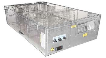
4 FH - GH Dehumidifiers for radiant cooling systems FH GH FH - GH The dehumidifiers FH and GH series are high performance units, equipped with robust galvanised steel frame, properly designed to operate in combination with radiant cooling systems. The FH units have been designed for wall mounting installation while the GH series are suitable for false ceiling and ducted applications. All units are provided with air filter, stainless steel drip tray and built-in microprocessor control. The units are also provided, standard, with pre and post cooling coil to enhance the performances and to control the air supply temperature. FH and GH units, anyway, can operate even without pre and post cooling coils, this option could be very useful in middle seasons when it is necessary to dry but the air conditioning system is not in operation. All the units are fully assembled and wired in the factory, carefully evacuated and dried with after leak tests under pressure and they are charged with environmental friendly refrigerant gases. They are fully tested before shipment; the units are conform to European Directives and are individually marked with CE label and Conformity Declaration. VERSIONS Version suitable for swimming pool installation: Supplied with painted frame and heat exchangers suitable for swimming pool WZ version: Units supplied with double condenser (the first is an air condenser, the second is a water one) and of a logic which allows the dehumidification with neutrum air or with cooled air. ACCESSORIES CTFH: Galvanized steel template (only FH). GRFH: Wood return and supply grill (only FH). HYGR: Remote mechanical hygrostat. HYGR: Remote mechanical hygrostat + thermostat (WZ versions only). PMBH: Delivery and return plenum 90. SWPK: Painted frame + heat exchangers suitable for swimming pool. PRPO: without pre and post cooling waters coils. 96
5 FH - GH FH - FHWZ Models Moisture removed (1) Cooling capacity (1) Total power input (1) Max power input Max input current Peak current Air flow Refrigerant Water flow Pressure drop Sound pressure (2) Temperature operating range Campo di lavoro umidità Power supply 25 25WZ l/24h 20,1 20,1 W W W A 2,7 2,7 A 18,1 18,1 m 3 /h R134a R134a l/h kpa 8 7,8 db(a) C % V/Ph/Hz 230/1/50 230/1/50 FH - GH GH - GHWZ Models Moisture removed (1) Cooling capacity (1) Total power input (1) Max power input Max input current Peak current Water flow Pressure drop Air flow Available static pressure (max. speed) Refrigerant Sound pressure (2) Temperature operating range Campo di lavoro umidità Power supply 25 25WZ 50 50WZ WZ WZ l/24h 20,1 20,1 48,5 48,5 87,2 87,2 164,0 164,0 W W W A 2,7 2,7 5,0 5,0 8,1 8,1 14,4 14,4 A 18,1 18,1 20,7 20,7 35,9 35,9 63,0 63,0 l/h kpa 8,0 7,8 17,0 42,0 32,0 39,5 48,0 64,0 m 3 /h Pa R134a R134a R407C R407C R407C R407C R407C R407C db(a) C % V/Ph/Hz 230/1/50 230/1/50 230/1/50 230/1/50 230/1/50 230/1/50 230/1/50 230/1/50 Performance refer to the following conditions: (1) Room temperature 26 C; relative humidity 65% with cold water coil water inlet temp. 15 C. (2) Sound pressure level measured at 1 mt from the unit in free field conditions according to ISO 9614, minimum fan speed.(only for FH versions) 97
6 FH - GH FH - GH FRAME All units FH-GH series are made from hotgalvanised thick sheet metal, to ensure the best resistance against the corrosions. The frame is self-supporting with removable panels. The drip tray is present standard in all units and is made of plastic material for model 25 and in metal material for models REFRIGERANT CIRCUIT The refrigerant circuit is made by using international primary brands components and according to ISO 97/23 concerning welding procedures. The refrigerant gas used in these units is R134a for the model 25 and R407C for the models The refrigerant circuit includes: filter drier, capillary expansion device, Schrader valves for maintenance and control, pressure safety device (according to PED regulation). COMPRESSOR The compressor (for model 25) is alternative or rotative type (for models ), equipped with crankcase heater and thermal overload protection by a klixon embedded in the motor winding. It s mounted on rubber vibration dampers to reduce the noise. CONDENSER AND EVAPORATOR The condensers and evaporators are made of copper pipes and aluminium fins. The diameter of the copper pipes is 3/8 and the thickness of the aluminium fins is 0,1 mm. The tubes are mechanically expanded into the aluminium fins to improve the heat exchange factor. The geometry of these condensers guarantees a low air side pressure drop and then the use of low rotation (and low noise emission) fans. All the units have a stainless steel drip tray. Besides this, each evaporator is supplied of a temperature probe used as automatic antifreeze probe. In all units WZ besides these exchangers, there is a third stainless steel INOX AISI 316 plate exchanger used us condenser in cooling modality. PRE AND POST WATER COOLING COILS The pre and post cold water coils are made of copper pipes and aluminium fins. The di- ameter of the copper pipes is 3/8 and the thickness of the aluminium fins is 0,1 mm. The tubes are mechanically expanded into the aluminium fins to improve the heat exchange factor. The pre-cooling coil is used to increase the dehumidification capacity of the unit, while the post-cooling coil is used to keep the outlet air temperature at the same inlet value. In WZ version only the pre cooled water coil is present. FAN The supply fan is centrifugal type, double inlet with forwards blades, dynamically and statically balanced and directly connected to a 3 speed fan motor. AIR FILTER For the model GH it s supplied standard with the unit and it s built in nylon. It can be removed for differential disposal, class G2, according to EN 779:2002. Regarding the model GH 100-GH 200 instead, it s made of filtering material in synthetic fibre without electrostatic charge. It can be removed for differential disposal, class G3, according to EN 779:2002 MICROPROCESSOR All units FH-GH are supplied standard with microprocessor controls. The microprocessor controls the following functions: compressor timing, automatic defrost cycles and alarms. An appropriate LCD display shows the operation mode of the unit, set point and alarms. ELECTRIC BOX The electric switch board is made according to electromagnetic compatibility norms CEE 73/23 and 89/336. The accessibility to the board is possible after removing the front panel of the unit. Ready for the connection to the power and to the consensus control, The terminal board is also supplied with voltage free contacts for remote ON- OFF. The terminal block is also built with a clean contact to allow the operation of single-mode ventilation, while the second for the cooling version (WZ). By closing the first contact, only the fan is abled to work, while the dehumidification is disabled. CONTROL AND PROTECTION DEVICES All units are supplied with the following control and protection devices: defrost thermostat, which signals to the microprocessor control that a defrost cycle is needed and controls its termination (only for GH WZ and GH WZ). Water temperature sensor, that signals to the microprocessor the eventual overcome of the hot water temperature set point in the pre and post water coils during operation. In this condition the compressor is disconnected while the fan always run and, when the water temperature returns within the operation limits, restarts the compressor. The water sensor stops the compressor when the water temperature is above 35 C. The eventual use of the dehumidifier as heating device during winter season requires an additional remote thermostat with seasonal change over (not supplied). In the all WZ version, it s also supplied a high pressure switch which disable the unit operation when the limit is overcome. TEST All the units are fully assembled and wired at the factory, carefully evacuated and dried after leak tests under pressure and then charged with ecologic refrigerant. They are all fully operational tested before shipment. They all conform to European Directives and are individually marked with the CE label and provided with Conformity Declaration. 98
7 FH - GH FH - FHWZ Versions Limit probe High pressure switch Galvanized steel template Wood return and supply grill Remote mechanical hygrostat Remote mechanical hygrostat + thermostat Painted frame + heat exchangers suitable for swimming pool Code 25 25WZ CTFH GRFH HYGR HYGR SWPK Standard, Optional, Not available. GH - GHWZ Versions Limit probe High pressure switch Defrost thermostat Remote mechanical hygrostat Painted frame + heat exchangers suitable for swimming pool Units supplied without pre and post cooling waters coils Remote mechanical hygrostat + thermostat Delivery and return plenum 90 Code 25 25WZ 50 50WZ WZ WZ HYGR SWPK PRPO HYGR CANA FH - GH Standard, Optional, Not available. FH B C B C B C A A A 1 2 Mod. A (mm) B (mm) C (mm) Kg /38 (1) , ,6 -- (1) WZ Version
8 FH - GH B C A Mod. A (mm) B (mm) C (mm) Kg WZ WZ WZ WZ FH - GH REFRIGERANT CIRCUIT STANDARD VERSION The functioning of the dehumidifier model FH-GH is as follows: the fan takes the air from the ambient (7) and it s made go through the filter (1) and the pre-cooling water coil (2) where it s cooled and brought to a condition closed to saturation. Now it passes through the evaporating coil (3) where it s fatherly cooled and dehumidified. The air passes now through the condensing coil (5) where it s post heated (with a constant humidity) and in the postcooling coil (6) where it s reported to the required conditions. All the dehumidifiers model FH-GH can work without the help of the pre and post cooling coils. This function is very useful in case there is the request of dehumidification in middle-season or when the chiller is off. Obviously, if the unit works without the help of the cold water, the air in outlet will be hotter than the air in inlet. REFRIGERANT CIRCUIT WZ VERSION The operation of the dehumidifier model GH is as follows: the fan takes the air from the ambient (7) and it s made go through the filter (1) and the pre-cooling water coil (2) where it s cooled and brought to a condition closed to saturation. Now it passes through the evaporating coil (3) where it s fatherly cooled and dehumidified. At this point there are two possible modalities: Modality with neutrum air. The air passes now through the condensing coil (5) which allows to condensate the 50% of the total gas, (the unit condensate the 50% on air with the heat exchanger (5) and the 50% in water with the heat exchanger (10)) then there is the post-heating so that to avoid to send air in the ambient in neutrum thermic conditions. Modality with cooled air. The unit condensates the 100% in water through the heat exchanger (10). The air, then, go through the condenser (5) (disabled) where does not change its characteristics (temperature and humidity). 100
9 FH - GH STANDARD VERSION WZ VERSION Air filter Pre-cooling coil Evaporator Compressor Condenser Post-cooling coil Fan Dry filter Expansion device Condenser water FH - GH DISCHARGE PLENUM MOD mm 505 mm 300 mm 160 mm 200 mm 615 mm 101


10 GHE Dehumidifiers for radiant cooling systems with heat recovery GHE The dehumidifiers with heat recovery of high efficiency series GHE were designed to provide dehumidification and fresh air in a residential area with very high energy efficiency, combined with radiant cooling systems. The units have been designed to grant the dehumidification either under conditions of thermally neutral air or in terms of air-cooled, managing small air flow thus avoiding annoying tiny air currents typical of traditional air conditioning systems. The units consist of a direct expansion cooling system combined with a cross flow heat exchanger highly efficient, designed for heat recovery and air exchange environment in compliance with applicable regional and national lows. VERSIONS All units are supplied with double condenser (the first is an air condenser, the second is a water one) and of a logic which allows the dehumidification with neutrum air or with cooled air. ACCESSORIES HYGR: Remote mechanical hygrostat + thermostat (WZ versions only). PCRL: Remote mechanical hygrostat. RGDD: Built in electronic temperature-humidity sensor. INSE: Serial interface card RS485. FAEL: High efficiency electronic air filter H
11 GHE Models GHE Useful dehumidification capacity (from the net hygroscopic content of the external air) (1) Total cooling Power (latent + sensible) (1) Recovered winter heating power (2) Efficiency winter recovery (2) Efficiency summer recovery (1) Power supply Compressor absorbed power (1) Supply fan absorbed power: minimum nominal maximum Return fan absorbed power Supply fan nominal useful prevalence Return fan nominal useful prevalence Min-max coil water flow Min-max water pressure drop Outdoor air flow Supply air flow Coolant type Sound power level (3) Sound Pressure Level (4) l/24h 30,1 61,8 W W % 90% 90% % 70% 70% V/Ph/Hz 230/1/50 230/1/50 W W W Pa Pa l/h kpa m 3 /h m 3 /h R134a R410A db(a) db(a) GHE TYPICAL INSTALLATION Supply air flow Exhaust air intake Exhaust Air GHE Recirculating Air Exhaust air intake Fresh Air Supply air flow Exhaust air intake Supply air flow Performance refer to the following conditions: (1) Room Temp. 26 C; 65% RU; Ambient Temp. 35 C; 50% RU; Fresh Air System volume 130 m 3 /h (GHE25),250 m 3 /h(ghe50); Water IN 15 C, Water Flow 250 l/h(ghe25), 350l/h(GHE50). (2) Ambient Temp. -5 C; 80% RU; Room Temp. 20 C; Fresh Air system at maximum. (3) Sound Power level according to ISO (4) Sound Pressure level measured at 1 mt from the unit in free field conditions according with ISO 9614, at the normal working conditions
12 GHE GHE FRAME All units are made from hot-galvanised thick sheet metal, to ensure the best resistance against the corrosions. The frame is selfsupporting with removable panels. The drip tray is present standard in all units. REFRIGERANT CIRCUIT The refrigerant circuit is made by using international primary brands components and according to ISO 97/23 concerning welding procedures. The refrigerant gas used in these units is R134a for the model 25 and R407C for the models 50. COMPRESSOR The compressor is alternative for model 25 and rotative type for model 50., equipped and thermal overload protection by a klixon embedded in the motor winding. It s mounted on rubber vibration dampers to reduce the noise. HEAT EXCHANGERS The heat exchangers are made of copper pipes and aluminium fins. The diameter of the copper pipes is 3/8 and the thickness of the aluminium fins is 0,1 mm. The tubes are mechanically expanded into the aluminium fins to improve the heat exchange factor. The geometry of these condensers guarantees a low air side pressure drop and then the use of low rotation (and low noise emission) fans. All the units have a stainless steel drip tray. Besides this, each evaporator is supplied of a temperature probe used as automatic antifreeze probe. FANS The supply fan is centrifugal type, double inlet with forwards blades, with EC Fan motor directly connected. The exhaust fan is plug fan type with backwards blades, with EC fan motor directly connected. AIR FILTER It s supplied standard with the unit. It s made of filtering material in synthetic fibre without electrostatic charge. It can be removed for differential disposal, class G4, according to EN 779:2002. HEAT RECOVERY Hexagonal cross-flow heat recovery with PVC plates, high efficiency (90%). ADJUSTMENT TRIMMERS Used during calibration of fans air flow depending on the ducts pressure drop. Main components MICROPROCESSOR All GHE units are supplied with an advanced software for the complete control of the hydronic and air distribution side. The software can manage: - The management of the operation according to a probe of temperature and humidity. - Activation of the dehumidification based on the pre set humidity conditions. - Activation of of winter or summer sensible load integration, according to the summer or winter set point - Management of supply air temperature through discharge limit probe sensor (standard). - Modulating valve for the proper management of the water battery power - Ventilation Management directly from builtin timer in the microprocessor (optional). - Management damper - Machine Allarm display - Supervisor and BMS connection through serial card RS485 (Optional) a/o XWEB Module (Optional). - Clogged filters management (optional). - Antifreeze management. - Summer/Winter commutation Air filter 10 2 Pre-Cooling coil 11 3 Evaporator 12 4 Compressor 13 5 Air Condenser 14 6 Solenoid Valve 15 7 Supply fan with EC 16 8 Dryer Filter 17 9 Body rolling 18 Water condenser Exhaust fan with EC motor High efficiency cross-flow heat recovery Return motorized damper WC exhaust air Fresh air Exhaust Air Electrical Panel Modulating 3-way valve 104
13 GHE REFRIGERANT CIRCUIT FUNCTIONING PRINCIPLES The functioning of the dehumidifier model GHE is as follows: the fan takes the air humid from the ambient through the fan (7) and it s made go through the filter (1) and the cross-flow heat (12) pre-cooling water coil (2) where it s cooled and brought to a condition closed to saturation. Now it passes through the evaporating coil (3) where it s fatherly cooled and dehumidified. At this time the functionality mode may be. The air passes now through the condensing coil (5) where it s post heated (with a constant humidity) and in cooling, when the solenoid valve (6) open where it s reported to the required conditions. Dehumidification with neutral air: The cooling system works partially in the water through the heat exchanger (10) and partially in the air with the heat exchanger (5) which will then make a post-heating at constant humidity blowing air in in the room in thermally neutral conditions. Dehumidification with cooling: The cooling circuit, in this case, performing works 100% of the condensation in the water through the heat exchanger (10), the heat exchanger (5) is intercepted by the valve (6) and the air supplied in the room is the same as leaving the evaporator coil (3), cold and dried. Direct Expansion + Water Coil Compressor Recirculation damper EC Fan adjustable trimmer Exhaust Air Filter Control panel with display GHE Hight Efficiency Heat Recovery Supply Fan with EC motor Exhaust Fan with EC motor Plate Exchanger AERAULIC CIRCUIT FUNCTIONING PRINCIPLES: GHE 25 units can operate with a flow rate of outdoor air from 80 to 130 m 3 /h (140 to 260 m3/h for the model GHE 50), to ensure sufficient supply air changes in the room having a variable volume by 260 m 3 (0.5 vol/h) to 460 m 3 (0.3 vol / h), in compliance with regional and national regulations. The air flow rate of discharge can vary from 80 to 130 m 3 /h ( m 3 /h for the model 50) in the winter mode, and is fixed to 260 m 3 /h (500 m 3 /h for the model 50) in summer mode. The cross-flow heat exchanger of high efficiency is designed to ensure a recovery rating of 90% in terms of air temperature -5 C and air temperature 20 C. The stale air is expelled from the environment by the fan (1), while the outside air is sucked through the fan (2). The proper balance of air flows is ensured by the damper (3) that handles both the balance of flows of air that the air flow recirculation summer. Return Air (max. 50%) 3 Return Air W.C. (max. 50%) Fresh Air (max. 50%) Exhaust Air (max. 50% 1 2 Supply Air 100% 105
14 GHE Whit this selected mode the unit renews the ambient air with the outside through the heat exchanger for high efficiency, air flow is increased so as to allow operation of refrigerant circuit; for this purpose the r recycling damper will be open, the supply fan is operated at maximum capacity and the unit works with external air and partial recirculation. SUMMER OPERATION (COMPRESSON ON) THE POSSIBLE FUNCTIONS IN THIS CONFIGURATION ARE - Renewal + Air Dryers neutral: The condensing unit partially in air and partially in the water through the condenser plate, obtaining dry air and thermally neutral. - Renewal + Dehumidification with cooling: The unit operates with 100% of the condensation water, obtaining dry and cooled air. Return Air (max. 50%) Return Air W.C. (max. 50%) GHE Fresh Air (max. 50%) Exhaust Air (max. 50% Supply Air 100% WINTER OPERATION AND MIDDLE SEASON (COMPRESSON OFF) Whit this selected mode, the unit renews the ambient air with the outside through the heat exchanger of high efficiency. The air flow is reduced to the value required by the standard ( vol/h), the recirculation damper is closed and the unit operates with 100% fresh air. THE POSSIBLE FUNCTIONS IN THIS CONFIGURATION ARE - Renewal with heated air: The compressor is switched off, the battery can be supplied with hot water from radiant system. (even due to the high efficiency of the heat exchanger, is able to obtain a supply air temperature 17 C, without using hot water and ambient air temperature of -5 C), and behaves like a normal air handling with recovery. Return Air W.C. (max. 50%) Fresh Air (max. 50%) Exhaust Air (max. 50% Supply Air 100% 106
15 GHE Versions GHE Microprocessor control Flow meter Modulating 3-way valve Supply & Return EC fans G4 air filter Adjustable Trimmers High Efficiency Heat Recovery Remote control Panel Thermo- Mechanical remote Hygrostat Umidity and Temperature electronic probe sensor Serial interface card RS485 High efficiency electronic air filter Code PCRL HYGR RGDD INSE FAEL Standard, Optional, Not available. Recovery Mix flow Pre-Cooling Evaporator Condenser (if active) GHE A C B Mod. A (mm) B (mm) C (mm) Kg


16 FHE Dehumidifiers for radiant cooling systems with heat recovery FHE The dehumidifiers with heat recovery of high efficiency series FHE were designed to provide dehumidification and fresh air in a residential area with very high energy efficiency, combined with radiant cooling systems. The units have been designed to grant the dehumidification either under conditions of thermally neutral air or in terms of air-cooled, managing small air flow thus avoiding annoying tiny air currents typical of traditional air conditioning systems. The units consist of a direct expansion cooling system combined with a cross flow heat exchanger highly efficient, designed for heat recovery and air exchange environment in compliance with applicable regional and national lows. VERSIONS All units are supplied with double condenser (the first is an air condenser, the second is a water one) and of a logic which allows the dehumidification with neutrum air or with cooled air. ACCESSORIES PCRL: Remote mechanical hygrostat. RGDD: Built in remote electronic temperature-humidity sensor. INSE: Serial interface card RS485. FAEL: High efficiency electronic air filter H
 Efficiency summer recovery (1) Power supply Compressor absorbed power (1) Supply fan absorbed power: minimum nominal maximum Return fan absorbed power Supply fan nominal useful")
17 FHE Models FHE Useful dehumidification capacity (from the net hygroscopic content of the external air) (1) Total cooling Power (latent + sensible) (1) Recovered winter heating power (2) Efficiency winter recovery (2) Efficiency summer recovery (1) Power supply Compressor absorbed power (1) Supply fan absorbed power: minimum nominal maximum Return fan absorbed power Supply fan nominal useful prevalence Return fan nominal useful prevalence Min-max coil water flow Min-max water pressure drop Outdoor air flow Supply air flow Coolant type Sound power level (3) Sound Pressure Level (4) 25 l/24h 30,1 W 1380 W 950 % 90% % 70% V/Ph/Hz 230/1/50 W 340 W W Pa Pa l/h kpa 38 m 3 /h m 3 /h R134a db(a) 47 db(a) 39 FHE TYPICAL INSTALLATION Supply air flow Exhaust air intake Exhaust Air Fresh Air Recirculating Air Performance refer to the following conditions: (1) Room Temp. 26 C; 65% RU; Ambient Temp. 35 C; 50% RU; Fresh Air System volume 130 m3/h; Water IN 15 C, Water Flow 250 l/h. (2) Ambient Temp. -5 C; 80% RU; Room Temp. 20 C; Fresh Air system at maximum. (3) Sound Power level according to ISO (4) Sound Pressure level measured at 1 mt from the unit in free field conditions according with ISO 9614, at the normal working conditions
18 FHE FHE FRAME All units are made from hot-galvanised thick sheet metal, painted with polyurethane powder enamel and stoved at 180 C to ensure the best resistance against the corrosions. The frame is self-supporting with removable panels. The drip tray is made in painted galvanized steel and it is present in all units. The standard colour is RAL REFRIGERANT CIRCUIT The refrigerant circuit is made by using international primary brands components and according to ISO 97/23 concerning welding procedures. The refrigerant gas used in is R134a. COMPRESSOR The compressor is alternative type equipped and thermal overload protection by a klixon embedded in the motor winding. It s mounted on rubber vibration dampers to reduce the noise. HEAT EXCHANGERS The heat exchangers are made of copper pipes and aluminium fins. The diameter of the copper pipes is 3/8 and the thickness of the aluminium fins is 0,1 mm. FANS The supply fan is centrifugal type, double inlet with forwards blades, with EC Fan motor directly connected. The exhaust fan is plug fan type with backwards blades, with EC fan motor directly connected. AIR FILTER It s supplied standard with the unit. It s made of filtering material in synthetic fibre without electrostatic charge. It can be removed for differential disposal, class G4, according to EN 779:2002. HEAT RECOVERY Hexagonal cross-flow regenerator with PVC plates, high efficiency (90%). ADJUSTMENT TRIMMERS Used during calibration of fans air flow depending on the ducts pressure drop. MICROPROCESSOR All FHE units are supplied with an advanced software for the complete control of the hydronic and air distribution side. The software can manage: - The management of the operation according to a probe of temperature and humidity. - Activation of the dehumidification based on the pre set humidity conditions. - Activation of winter or summer sensible load integration, according to the summer or winter set point - Management of supply air temperature through discharge limit probe sensor (standard). - Modulating valve for the proper management of the water battery power. - Ventilation Management directly from built-in timer in the microprocessor (optional). - Management damper - Machine alarm display - Supervisor and BMS connection through serial card RS485 (Standard fitted) a/o XWEB Module (Optional). - Clogged filters management (optional). - Antifreeze management. - Summer/Winter commutation. Main components Air filter Pre-Cooling coil Evaporator Compressor Air Condenser Solenoid Valve Supply fan with EC Dryer Filter Body rolling Water condenser Exhaust fan with EC motor High efficiency cross-flow heat recovery Return motorized damper WC exhaust air Fresh air Exhaust Air Supply air flow Electrical Panel Modulating 3-way valve Electronic filter
19 FHE REFRIGERANT CIRCUIT FUNCTIONING PRINCIPLES The functioning of the dehumidifier model FHE is as follows: the fan takes the air humid from the ambient through the fan (7) and it s made go through the filter (1), the cross-flow heat (12) and the pre-cooling water coil (2) where it s cooled and brought to a condition closed to saturation. Now it passes through the evaporating coil (3) where it s fatherly cooled and dehumidified. At this time the functionality mode may be: Dehumidification with neutral air : The cooling system works partially in the water through the heat exchanger (10) and partially in the air with the heat exchanger (5) which will then make a post-heating at constant humidity blowing air in the room in thermally neutral conditions. Dehumidification with cooling: The cooling circuit, in this case, works performing 100% of the condensation in the water through the heat exchanger (10).The heat exchanger (5) is intercepted by the valve (6) and the air supplied in the room is the same as leaving the evaporator coil (3), cold and dried. Air Filter Control panel with display High Efficiency Heat Recovery Direct Expansion + Water Coil Air Filter Motorized regulaton damper Supply Fan with EC motor Exhaust Fan with EC motor Plate Exchanger Compressor FHE AERAULIC CIRCUIT FUNCTIONING PRINCIPLE FHE units can operate with a flow rate of outdoor air from 80 to 130 m 3 /h, to ensure sufficient supply air changes in the room having a variable volume by 430 m 3 (0,3 vol/h) in compliance with regional and national regulations. The air flow rate of discharge can vary from 80 to 130 m 3 /h in the winter mode, and is fixed to 260 m 3 /h in summer mode. The cross-flow heat exchanger of high efficiency is designed to ensure a recovery rating of 90% in terms of air temperature -5 C and air temperature 20 C. The stale air is expelled from the environment by the fan (1), while the outside air is sucked through the fan (2). The proper balance of air flows is ensured by the damper (3) that handles both the balance of flows of air and the air flow recirculation summer. Return Air W.C. (max. 50%) 3 Return Air (max. 50%) Fresh Air (max. 50%) Exhaust Air (max. 50% 1 Supply Air 100%
20 FHE SUMMER OPERATION (COMPRESSOR ON) Whit this selected mode, the unit renews the ambient air with the outside through the heat exchanger for high efficiency, air flow is increased so as to allow operation of refrigerant circuit; for this purpose the recycling damper will be open, the supply fan is operated at the maximum capacity and the unit works with external air and partial recirculation. Return Air W.C. (max. 50%) Fresh Air (max. 50%) Exhaust Air (max. 50% Supply Air 100% 2 THE POSSIBLE FUNCTIONS IN THIS CONFIGURATION ARE FHE - Renewal + Air Dryers neutral: The condensing unit partially in air and partially in the water through the condenser plate, obtaining dry air and thermally neutral. - Renewal + Dehumidification with cooling: The unit operates with 100% of the condensation water, obtaining dry and cooled air. 3 1 Return Air (max. 50%) WINTER OPERATION AND MIDDLE SEA- SON (COMPRESSOR OFF) Whit this selected mode, the unit renews the ambient air with the outside through the heat exchanger of high efficiency. The air flow is reduced to the value required by the standard (0,3 0,5 Vol/h), the recirculation damper is closed and the unit operates with 100% fresh air. Return Air W.C. (max. 50%) Fresh Air (max. 50%) Exhaust Air (max. 50%) Supply Air 50% THE POSSIBLE FUNCTIONS IN THIS CONFIGURATION ARE - Renewal with heated air: The compressor is switched off, the battery can be supplied with hot water from radiant system. (even due to the high efficiency of the heat exchanger, is able to obtain a supply air temperature 17 C, without using hot water and ambient air temperature of -5 C), and behaves like a normal air handling with recovery. 112
21 FHE Versions FHE Microprocessor control Flow meter Modulating 3-way valve Supply & Return EC fans G4 air filter Adjustable Trimmers High Efficiency Heat Recovery Umidity and Temperature electronic probe sensor Remote control Panel High efficiency electronic air filter H10 Serial interface card RS485 Code RGDD PCRL FAEL INSE 25 Standard, Optional, Not available. Recovery Mix flow Pre-Cooling Evaporator Condenser (if active) FHE B C A Mod. A (mm) B (mm) C (mm) Kg

22 DH - DR Standard Dehumidifiers DH DR DH - DR DH dehumidifiers series are high-performances units especially designed for industrial or commercial purposes where humidity level should be controlled or water vapour condensation should be prevented. These units are particularly indicated for archives, ironing rooms, bookstores, cheese factories, underground rooms, cellars and industrial sites where high humidity level is present. This series comprises 3 basic models which cover a capacity range from 75 to 124 l/24h. DH units are designed for easy maintenance and service, each part being readily accessible. VERSIONS Standard version available in 3 different sizes Hot gas defrost version (s): Beside the components of the standard version, the unit is supplied with a solenoid valves set for the hot ga s injection used to defrost the evaporator in case of severe working conditions. The hot gas injection allows a faster defrost time and this permits to use this unit in areas with lower temperatures (down to 1 C) compared to the standard version ACCESSORIES HYGR: Integrated mechanical hygrostat. HYGR: Remote mechanical hygrostat. INOX: Stainless steel frame. PM: Available static pressure 200Pa. TROL: Floor trolley version. 114
23 DH - DR Models DH Moisture removed (1) Total power input (1) Max power input (2) Max input current Peak current Air flow Refrigerant Available static pressure Sound Pressure (3) Temperature operating range Humidity operating range Power supply 75 75S S S l/24h 75,1 75,1 93,7 93,7 124,0 124,0 kw 1,3 1,3 1,6 1,6 1,8 1,8 kw 1,6 1,6 2,0 2,0 2,2 2,2 A 5,9 5,9 6,8 6,8 7,4 7,4 A 22,2 22,2 31,2 31,2 35,2 35,2 m 3 /h R407C R407C R407C R407C R407C R407C Pa db(a) C % V/Ph/Hz 230/1/50 230/1/50 230/1/50 230/1/50 230/1/50 230/1/50 Models DR Moisture removed (1) Total power input (1) Max power input (2) Max input current Peak current Air flow Refrigerant Available static pressure Sound Pressure (3) Temperature operating range Humidity operating range Power supply l/24h 75,1 93,7 124,0 kw 1,3 1,6 1,8 kw 1,6 2,0 2,2 A 5,9 6,8 7,4 A 22,2 31,2 35,2 m 3 /h R407C R407C R407C Pa db(a) C % V/Ph/Hz 230/1/50 230/1/50 230/1/50 DH - DR Performance refer to the following conditions: (1) Room temperature 30 C; relative humidity 80%. (2) Room temperature 35 C; relative humidity 80%. (3) Sound pressure level measured at 1 mt from the unit in free field conditions according to ISO
24 DH - DR DH - DR FRAME All DH/DR units are made from hot-galvanised thick sheet metal, painted with polyurethane powder enamel at 180 C to ensure the best resistance against the atmospheric agents. The frame is selfsupporting with removable panels. The drip tray is present standard in all DH units and it s in stainless steel. The colour of the units is RAL REFRIGERANT CIRCUIT The refrigerant gas used in these units is R407C. The refrigerant circuit is made by using international primary brands components and according to ISO 97/23 concerning welding procedures. The refrigerant circuit includes: filter drier, thermal expansion valve with external equalizer, Schrader valves form maintenance and control, pressure safety device (according to PED regulation). COMPRESSOR The compressor is rotative type with crankcase heater and thermal overload protection by a klixon embedded in the motor winding. It s mounted on rubber vibration dampers and, by request, it can be supplied with some jackets to reduce the noise (accessory). CONDENSER AND EVAPORATOR The condensers and evaporators are made of copper pipes and aluminium fins. The diameter of the copper pipes is 3/8 and the thickness of the aluminium fins is 0,1 mm. The tubes are mechanically expanded into the aluminium fins to improve the heat exchange factor. The geometry of these condensers guarantees a low air side pressure drop and then the use of low rotation (and low noise emission) fans. All the units have a stainless steel drip tray. Besides this, each evaporator is supplied of a temperature probe used as automatic antifreeze probe. FAN The fan is centrifugal type. It s statically and dynamically balanced and supplied complete of the safety fan guard according to EN 294. It s mounted on the unit frame by interposition of rubber vibration dampers. The electric motor is at 4 poles (about 1500 rpm). Connected to the fan by belts and pulleys and it s equipped of an integrated thermal overload protection. The protection class of the motors is IP 54. AIR FILTER It s supplied standard with the unit. It s made of filtering material in synthetic fibre without electrostatic charge. It can be removed for differential disposal, class G3, according to EN 779:2002 MICROPROCESSOR All DH / DR units are supplied standard with microprocessor controls. The microprocessor controls the following functions: compressor timing, automatic defrost cycles and alarms. An appropriate LCD display shows the operation mode of the unit, set point and alarms ELECTRIC BOX The electric switch board is made according to electromagnetic compatibility norms CEE 73/23 and 89/336. The accessibility to the board is possible through the accessories panel. The following components are standard installed: compressors fuses, control circuit automatic breakers, compressor contactors. The terminal board is also supplied with voltage free contacts for remote ON-OFF. CONTROL AND PROTECTION DEVICES All units are supplied with the following control and protection devices: defrost thermostat, which signals to the microprocessor control that a defrost cycle is needed and controls its termination, high pressure switch with manual reset, low pressure switch with automatic reset, high pressure safety valve, compressor thermal overload protection, fans thermal overload protection. TEST All the units are fully assembled and wired at the factory, carefully evacuated and dried after leak tests under pressure and then charged with refrigerant R407C. They are all fully operational tested before shipment. They all conform to European Directives and are individually marked with the CE label and provided with Conformity Declaration. 116
25 DH - DR Versions DH Integrated mechanical hygrostat Remote mechanical hygrostat Available static pressure 200 Pa Floor trolley version Stainless steel frame Code HYGR HYGR PM TROL INOX DH75 DH75S DH100 DH100S DH120 DH120S Standard, Optional, Not available. Versions DR Integrated mechanical hygrostat Remote mechanical hygrostat Code HYGR HYGR DR75 DR100 DR120 Standard, Optional, Not available. DH - DR DH DR B C B C A A Mod. A (mm) B (mm) C (mm) Kg Mod. A (mm) B (mm) C (mm) Kg


26 EH - EHD - EHZ Standard dehumidifiers EHD EH-EHZ EH - EHD - EHZ EHZ (Outdoor unit) EH dehumidifiers series are high-performances units especially designed for industrial or commercial purposes where humidity level should be controlled or water vapor condensation should be prevented. These units are particularly indicated for archives, ironing rooms, bookstores, cheese factories, underground rooms, cellars and industrial sites where high humidity level is present. This series comprises three basic models which cover a capacity range from 164 to 194 l/24h. EH units are designed for easy maintenance and service, each part being readily accessible and, when required, easily replaceable thus reducing service and maintenance costs. VERSIONS Hot gas defrost version (s): Beside the components of the standard version, the unit is supplied with a solenoid valves set for the hot ga s injection used to defrost the evaporator in case of severe working conditions. The hot gas injection allows a faster defrost time and this permits to use this unit in areas with lower temperatures (down to 1 C) compared to the standard version. EHD Version: neutral air dehumidifier: in addition to the base components, the unit is equipped with a partial air condenser, installed on the unit, designed to dissipate the extra heating load so that to ensure air neutral conditions in the ambient which has to be treated. VERSIONS Version with temperature control EHZ: These versions are supplied with a remote condenser and are used in those applications where it is necessary the simultaneous control of temperature and humidity: Dehumidification mode: the internal condenser is activated; the unit dehumidifies and heats up the room temperature;cooling mode: the remote condenser is activated; the unit dehumidifies and cools down the room temperature. ACCESSORIES FARC: Air filter with frame for ducted installation. HYGR: Integrated mechanical hygrostat. HYGR: Remote mechanical hygrostat. HYGR: Remote mechanical hygrostat + thermostat. INOX: Stainless steel frame. PM: Available static pressure 200 Pa. TROL: Floor trolley version. RP00: Desuperheater. 118
27 EH - EHD - EHZ Models EH - EHD Moisture removed (1) Total power input (1) Max power input (2) Max input current (2) Peak current Air flow Available static pressure Refrigerant Sound pressure (3) Temperature operating range Humidity operating range Power supply S S l/24h 164,3 164,3 194,0 194,0 kw 2,55 2,55 2,95 2,95 kw 3,2 3,2 3,4 3,4 A 5,9 5,9 7,6 7,6 A 25,7 25,7 34,5 34,5 m 3 /h Pa R407C R407C R407C R407C db(a) C (6) (6) % V/Ph/Hz 400/3+N/50 400/3+N/50 400/3+N/50 400/3+N/50 Models EHZ Moisture removed (1) Input power (1) Cooling capacity (4) Input power (4) Maximum input power (5) Maximum input current (5) Peak current Air flow Available static pressure Refrigerant Sound pressure (3) Temperature operating range Humidity operating range Power supply S l/24h 194,2 194,2 kw 2,95 2,95 kw 7,4 7,4 kw 2,7 2,7 kw 3,2 3,2 A 8,4 8,4 A 35,3 35,3 m 3 /h Pa R407C R407C db(a) C (6) % V/Ph/Hz 400/3+N/50 400/3+N/50 EH - EHD - EHZ Performance refer to the following conditions: (1) Room temperature 30 C; relative humidity 80%. (2) Room temperature 35 C; relative humidity 80%. (3) Sound pressure level measured at 1 mt from the unit in free field conditions according to ISO (4) Room temperature 30 C; relative humidity 80%; ambient temperature 35 C. (5) Room temperature 35 C; relative humidity 80%; ambient temperature 35 C. (6) S versions with hot gas defrost only
28 EH - EHD - EHZ EH - EHD - EHZ FRAME All EH units are made from hot-galvanised thick sheet metal, painted with polyurethane powder enamel at 180 C to ensure the best resistance against the atmospheric agents. The frame is self-supporting with removable panels. The drip tray is present standard in all EH units and it s in stainless steel. The colour of the units is RAL REFRIGERANT CIRCUIT The refrigerant gas used in these units is R407C. The refrigerant circuit is made by using international primary brands components and according to ISO 97/23 concerning welding procedures. The refrigerant circuit includes: sight glass, filter drier, thermal expansion valve with external equalizer, Schrader valves form maintenance and control, pressure safety device (according to PED regulation). COMPRESSOR The compressor is scroll type with crankcase heater and thermal overload protection by a klixon embedded in the motor winding. It s mounted on rubber vibration dampers and, by request, it can be supplied with some jackets to reduce the noise (accessory). The crankcase heater, when present, is always powered when the compressor is in stand-by. The inspection is possible through the frontal panel of the unit. CONDENSER AND EVAPORATOR The condensers and evaporators are made of copper pipes and aluminium fins. The diameter of the copper pipes is 3/8 and the thickness of the aluminium fins is 0,1 mm. The tubes are mechanically expanded into the aluminium fins to improve the heat exchange factor. The geometry of these condensers guarantees a low air side pressure drop and then the use of low rotation (and low noise emission) fans. All the units have a stainless steel drip tray. Besides this, each evaporator is supplied of a temperature probe used as automatic antifreeze probe. FAN The fan is centrifugal type. It s statically and dynamically balanced and supplied complete of the safety fan guard according to EN 294. It s mounted on the unit frame by interposition of rubber vibration dampers. The electric motor is at 4 poles (about 1500 rpm). Connected to the fan by belts and pulleys and it s equipped of an integrated thermal overload protection. The protection class of the motors is IP 54. AIR FILTER It s supplied standard with the unit. It s made of filtering material in synthetic fibre without electrostatic charge. It can be removed for differential disposal, class G3, according to EN 779:2002. MICROPROCESSOR All EH units are supplied standard with microprocessor controls. The microprocessor controls the following functions: compressor timing, automatic defrost cycles and alarms. An appropriate LCD display shows the operation mode of the unit, set point and alarms. ELECTRIC BOX The electric switch board is made according to electromagnetic compatibility norms CEE 73/23 and 89/336. The accessibility to the board is possible after removing the front panel of the unit and the OFF positioning of the main switch. In all EH units are installed, standard, the compressors sequence relay which disables the operation of the compressor in case the power supply phase sequence is not the correct one (scroll compressors in fact, can be damaged if they rotate reverse wise). The following components are also standard installed: main switch, magnetic-thermal switches (as a protection of pumps and fans), compressors fuses, control circuit automatic breakers, compressor contactors. The terminal board is also supplied with voltage free contacts for remote ON- OFF. CONTROL AND PROTECTION DEVICES All units are supplied with the following control and protection devices: defrost thermostat, which signals to the microprocessor control that a defrost cycle is needed and controls its termination, high pressure switch with manual reset, low pressure switch with automatic reset, high pressure safety valve, compressor thermal overload protection, fans thermal overload protection. TEST All the units are fully assembled and wired at the factory, carefully evacuated and dried after leak tests under pressure and then charged with refrigerant R407C. They are all fully operational tested before shipment. They all conform to European Directives and are individually marked with the CE label and provided with Conformity Declaration. REMOTE CONDENSER (Only EHZ versions) The remote condensers are made of copper pipes and aluminium fins. The diameter of the copper pipes is 3/8 and the thickness of the aluminium fins is 0,1 mm. The tubes are mechanically expanded into the aluminium fins to improve the heat exchange factor. The geometry of these condensers guarantees a low air side pressure drop and then the use of low rotation (and low noise emission) fans. The fans are axial type with aluminium aerofoil blades complete of the safety fan guard. The protection class of the motors is IP 54. Furthermore the remote condenser is supplied of the low ambient condensing pressure control. This device controls the cooling circuit condensing pressure at differents ambient temperatures, to keep it correct. DESUPERHEATER (Only EHD versions) The desuperheater is made of copper pipes and aluminium fins. The diameter of the copper pipes is 3/8 and the thickness of the aluminium fins is 0,1 mm. The tubes are mechanically expanded into the aluminium fins to improve the heat exchange factor. The fan of the desuperheater is axial type with aluminium aerofoil blades. It s statically and dynamically balanced and supplied complete of the safety fan guard according to EN It s mounted on the unit frame by interposition of rubber vibration dampers. 120
29 EH - EHD - EHZ Versions EH - EHD - EHZ Integrated mechanical hygrostat Remote mechanical hygrostat Remote mechanical hygrastat + thermostat Available static pressure 200 Pa Floor trolley version Stainless steel frame Air filter with frame for ducted installation Built in partial heat recovery version Code EH160 EH200 EHD160 EHD200 EHZ160 EHZ200 HYGR - - HYGR - - HYGR PM TROL - - INOX FARC Standard, Optional, Not available. USE EHD VERSION Supply air Return air Return air with partial heat recovery ON Supply air with partial heat recovery ON Return air with partial heat recovery ON EH - EHD - EHZ EH-EHZ EHD B C B C 362 mm 780 mm A 555 mm A Remote condenser (Only Z versions) Mod. A (mm) B (mm) C (mm) Kg Mod. A (mm) B (mm) C (mm) Kg


30 ITM - ITMD - ITMZ Standard dehumidifiers ITMD ITM-ITMZ ITM - ITMD - ITMZ ITMZ (Outdoor unit) ITM dehumidifiers series are high-performances units especially designed for industrial or commercial purposes where humidity level should be controlled or water vapour condensation should be prevented. These units are particularly indicated for archives, ironing rooms, bookstores, cheese factories, underground rooms, cellars and industrial sites where high humidity level is present. This series comprises 2 basic models which cover a capacity range from 330 to 415 l/24h. ITM units are designed for easy maintenance and service, each part being readily accessible and, when required, easily replaceable thus reducing service and maintenance costs. VERSIONI Hot gas defrost version (s): Beside the components of the standard version, the unit is supplied with a solenoid valves set for the hot ga s injection used to defrost the evaporator in case of severe working conditions. The hot gas injection allows a faster defrost time and this permits to use this unit in areas with lower temperatures (down to 1 C) compared to the standard version. VERSIONS Version with temperature control ITMZ: These versions are supplied with a remote condenser and are used in those applications where it is necessary the simultaneous control of temperature and humidity: Dehumidification mode: the internal condenser is activated; the unit dehumidifies and heats up the room temperature; Cooling mode: the remote condenser is activated; the unit dehumidifies and cools down the room temperature. ITMD Version: neutral air dehumidifier: in addition to the base components, the unit is equipped with a partial air condenser, installed on the unit, designed to dissipate the extra heating load so that to ensure air neutral conditions in the ambient which has to be treated. ACCESSORIES FARC: Air filter with frame for ducted installation. HYGR: Integrated mechanical hygrostat. HYGR: Remote mechanical hygrostat. HYGR: Remote mechanical hygrostat + thermostat. INOX: Stainless steel frame. PM: Available static pressure 200 Pa. TROL: Floor trolley version. 122
31 ITM - ITMD - ITMZ Models ITM - ITMD Moisture removed (1) Total power input (1) Max power input (2) Max power input (2) Peak current Air flow Available static pressure Refrigerant Sound pressure (3) Temperature operating range Humidity operating range Power supply ITM-ITMD330 ITM-ITMD330S ITM-ITMD400 ITM-ITMD400S l/24h 329,9 329,9 414,9 414,9 kw 5,3 5,3 6,6 6,6 kw 5,9 5,9 7,4 7,4 A 11,7 11,7 13,7 13,7 A 66,2 66,2 74,7 74,7 m 3 /h Pa R407C R407C R407C R407C db(a) C (6) (6) % V/Ph/Hz 400/3~+N/50 400/3~+N/50 400/3~+N/50 400/3~+N/50 Models ITMZ Moisture removed (1) Input power (1) Cooling capacity (4) Total power input (4) Max power input (5) Max input current (5) Peak current Air flow Available static pressure Refrigerant Sound pressure (3) Temperature operating range Humidity operating range Power supply ITMZ330 ITMZ330S ITMZ400 ITMZ400S l/24h 329,9 329,9 414,9 414,9 kw 5,3 5,3 6,6 6,6 kw 15,4 15,4 16,6 16,6 kw 5,3 5,3 6,6 6,6 kw 5,9 5,9 7,4 7,4 A 14,3 14,3 16,3 16,3 A 68,8 68,8 77,3 77,3 m 3 /h Pa R407C R407C R407C R407C db(a) C (6) (6) % V/Ph/Hz 400/3+N/50 400/3+N/50 400/3+N/50 400/3+N/50 ITM - ITMD - ITMZ Performance refer to the following conditions: (1) Room temperature 30 C; relative humidity 80%. (2) Room temperature 35 C; relative humidity 80%. (3) Sound pressure level measured at 1 mt from the unit in free field conditions according to ISO (4) Room temperature 30 C; relative humidity 80%; ambient temperature 35 C. (5) Room temperature 35 C; relative humidity 80%; ambient temperature 35 C. (6) S versions with hot gas defrost only
32 ITM - ITMD - ITMZ ITM - ITMD - ITMZ FRAME All ITM units are made from hot-galvanised thick sheet metal, painted with polyurethane powder enamel at 180 C to ensure the best resistance against the atmospheric agents. The frame is self-supporting with removable panels. The drip tray is present standard in all ITM units and it s in stainless steel. The colour of the units is RAL REFRIGERANT CIRCUIT The refrigerant gas used in these units is R407C. The refrigerant circuit is made by using international primary brands components and according to ISO 97/23 concerning welding procedures. The refrigerant circuit includes: sight glass, filter drier, thermal expansion valve with external equalizer, Schrader valves form maintenance and control, pressure safety device (according to PED regulation). COMPRESSOR The compressor is scroll type with crankcase heater and thermal overload protection by a klixon embedded in the motor winding. It s mounted on rubber vibration dampers and, by request, it can be supplied with some jackets to reduce the noise (accessory). The crankcase heater, when present, is always powered when the compressor is in stand-by. The inspection is possible through the frontal panel of the unit. CONDENSER AND EVAPORATOR The condensers and evaporators are made of copper pipes and aluminium fins. The diameter of the copper pipes is 3/8 and the thickness of the aluminium fins is 0,1 mm. The tubes are mechanically expanded into the aluminium fins to improve the heat exchange factor. The geometry of these condensers guarantees a low air side pressure drop and then the use of low rotation (and low noise emission) fans. All the units have a stainless steel drip tray. Besides this, each evaporator is supplied of a temperature probe used as automatic antifreeze probe. FAN The fan is centrifugal type. It s statically and dynamically balanced and supplied complete of the safety fan guard according to EN 294. It s mounted on the unit frame by interposition of rubber vibration dampers. The electric motor is at 4 poles (about 1500 rpm). Connected to the fan by belts and pulleys and it s equipped of an integrated thermal overload protection. The protection class of the motors is IP 54. AIR FILTER It s supplied standard with the unit. It s made of filtering material in synthetic fibre without electrostatic charge. It can be removed for differential disposal, class G3, according to EN 779:2002. MICROPROCESSOR All ITM units are supplied standard with microprocessor controls. The microprocessor controls the following functions: compressor timing, automatic defrost cycles, alarms. An appropriate LCD display shows the operation mode of the unit, set point and alarms. ELECTRIC BOX The electric switch board is made according to electromagnetic compatibility norms CEE 73/23 and 89/336. The accessibility to the board is possible after removing the front panel of the unit and the OFF positioning of the main switch. The moisture protection degree is IP55. In all ITM units are installed, standard, the compressors sequence relay which disables the operation of the compressor in case the power supply phase sequence is not the correct one (scroll compressors in fact, can be damaged if they rotate reverse wise). The following components are also standard installed: main switch, magneticthermal switches (as a protection of fans), compressors fuses, control circuit automatic breakers, compressor contactors. The terminal board is also supplied with voltage free contacts for remote ON-OFF. CONTROL AND PROTECTION DEVICES All units are supplied with the following control and protection devices: defrost thermostat, which signals to the microprocessor control that a defrost cycle is needed and controls its termination, high pressure switch with manual reset, low pressure switch with automatic reset, high pressure safety valve, compressor thermal overload protection, fans thermal overload protection. TEST All the units are fully assembled and wired at the factory, carefully evacuated and dried after leak tests under pressure and then charged with refrigerant R407C. They are all fully operational tested before shipment. They all conform to European Directives and are individually marked with the CE label and provided with Conformity Declaration. REMOTE CONDENSER The remote condensers are made of copper pipes and aluminium fins. The diameter of the copper pipes is 3/8 and the thickness of the aluminium fins is 0,1 mm. The tubes are mechanically expanded into the aluminium fins to improve the heat exchange factor. The geometry of these condensers guarantees a low air side pressure drop and then the use of low rotation (and low noise emission) fans. The fans are axial type with aluminium aerofoil blades complete of the safety fan guard. The protection class of the motors is IP 54. Furthermore the remote condenser is supplied of the low ambient condensing pressure control. This device controls the cooling circuit condensing pressure at differents ambient temperatures, to keep it correct. 124
33 ITM - ITMD - ITMZ Versions ITM - ITMD - ITMZ Integrated mechanical hygrostat Remoto mechanical hygrostat Remoto mechanical hygrostat + thermostat Available static pressure 200 Pa Floor trolley version Stainless steel frame Air filter with frame for ducted installation Built in partial heat recovery version Code ITM330 ITM400 ITMD330 ITMD400 ITMZ330 ITMZ400 HYGR HYGR HYGR PM TROL INOX FARC Standard, Optional, Not available. USE ITMD VERSION Supply air Supply air with partial heat recovery ON ITM - ITMD - ITMZ Return air Return air with partial heat recovery ON ITM - ITMZ ITMD B C B C A 362 mm 1980 mm A 555 mm Remote condenser (Only Z versions) Mod. A (mm) B (mm) C (mm) Kg Mod. A (mm) B (mm) C (mm) Kg


34 FL - FLD - FLZ Standard dehumidifiers FLD FL - FLD - FLZ FL FLZ (Outdoor unit) FL dehumidifiers series are high-performances units especially designed for industrial or commercial purposes where humidity level should be controlled or water vapour condensation should be prevented. These units are particularly indicated for archives, ironing rooms, bookstores, cheese factories, underground rooms, cellars and industrial sites where high humidity level is present. This series comprises 3 basic models which cover a capacity range from 564 to 940 l/24h. FL units are designed for easy maintenance and service, each part being readily accessible and, when required, easily replaceable thus reducing service and maintenance costs. VERSIONI Hot gas defrost version (S) Beside the components of the standard version, the unit is supplied with a solenoid valves set for the hot ga s injection used to defrost the evaporator in case of severe working conditions. The hot gas injection allows a faster defrost time and this permits to use this unit in areas with lower temperatures (down to 1 C) compared to the standard version. VERSIONS Version with temperature control FLZ: These versions are supplied with a remote condenser and are used in those applications where it is necessary the simultaneous control of temperature and humidity: Dehumidification mode: the internal condenser is activated; the unit dehumidifies and heats up the room temperature; Cooling mode: the remote condenser is activated; the unit dehumidifies and cools down the room temperature. FLD Version: neutral air dehumidifier: in addition to the base components, the unit is equipped with a partial air condenser, installed on the unit, designed to dissipate the extra heating load so that to ensure air neutral conditions in the ambient which has to be treated. ACCESSORIES FARC: Air filter with frame for ducted installation. HYGR: Integrated mechanical hygrostat. HYGR: Remote mechanical hygrostat. HYGR: Remote mechanical hygrostat + thermostat. INOX: Stainless steel frame. PM: Available static pressure 200 Pa. TROL: Floor trolley version. 126
35 FL - FLD - FLZ Models FL - FLD Moisture removed (1) Nominal input power (1) Max input power (2) Nominal input current (2) Peak current Air flow Available static pressure Refrigerant Sound pressure (3) Temperature operating range Humidity operating range Power supply FL-FLD560 FL-FLD560S FL-FLD740 FL-FLD740S FL-FLD940 FL-FLD940S l/24h 564,1 564,1 736,7 736,7 937,3 937,3 kw 8,7 8,7 11,3 738,5 14,8 14,8 kw 9,0 9,0 12,9 12,9 17,3 17,3 A 19,3 19,3 25,0 25,0 31,3 31,3 A 101,3 101,3 130,0 130,0 171,3 171,3 m 3 /h Pa R407C R407C R407C R407C R407C R407C db(a) C (6) (6) (6) % V/Ph/Hz 400/3+N/50 400/3+N/50 400/3+N/50 400/3+N/50 400/3+N/50 400/3+N/50 Models FLZ Moisture removed (1) Input power (1) Cooling capacity (4) Total power input (4) Max power input (5) Max input current (5) Peak current Air flow Available static pressure Refrigerant Sound pressure (3) Temperature operating range Humidity operating range Power supply FLZ560 FLZ560S FLZ740 FLZ740S FLZ940 FLZ940S l/24h 564,1 564,1 738,5 738,5 937,3 937,3 kw 8,7 8,7 11,3 11,3 14,8 14,8 kw 21,3 21,3 28,5 28,5 40,6 40,6 kw 9,1 9,1 11,7 11,7 15,3 15,3 kw 10,2 10,2 14,5 14,5 18,7 18,7 A 21,5 21,5 27,6 27,6 34,8 34,8 A 103,5 103,5 132,6 132,6 174,8 174,8 m 3 /h Pa R407C R407C R407C R407C R407C R407C db(a) C (6) (6) (6) % V/Ph/Hz 400/3+N/50 400/3+N/50 400/3+N/50 400/3+N/50 400/3+N/50 400/3+N/50 FL - FLD - FLZ Performances refer to the following conditions: (1) Room temperature 30 C; relative humidity 80%. (2) Room temperature 35 C; relative humidity 80%. (3) Sound pressure level measured at 1 mt from the unit in free field conditions according to ISO (4) Room temperature 30 C; relative humidity 80%; ambient temperature 35 C. (5) Room temperature 35 C; relative humidity 80%; ambient temperature 35 C. (6) S versions with hot gas defrost only
36 FL - FLD - FLZ FL - FLD - FLZ FRAME All FL units are made from hot-galvanised thick sheet metal, painted with polyurethane powder enamel at 180 C to ensure the best resistance against the atmospheric agents. The frame is self-supporting with removable panels. The drip tray is present standard in all FL units and it s in stainless steel. The colour of the units is RAL REFRIGERANT CIRCUIT The refrigerant gas used in these units is R407C. The refrigerant circuit is made by using international primary brands components and according to ISO 97/23 concerning welding procedures. The refrigerant circuit includes: sight glass, filter drier, thermal expansion valve with external equalizer, Schrader valves form maintenance and control, pressure safety device (according to PED regulation). COMPRESSOR The compressor is scroll type with crankcase heater and thermal overload protection by a klixon embedded in the motor winding. It s mounted on rubber vibration dampers and, by request, it can be supplied with some jackets to reduce the noise (accessory). The crankcase heater, when present, is always powered when the compressor is in stand-by. The inspection is possible through the frontal panel of the unit. CONDENSER AND EVAPORATOR The condensers and evaporators are made of copper pipes and aluminium fins. The diameter of the copper pipes is 3/8 and the thickness of the aluminium fins is 0,1 mm. The tubes are mechanically expanded into the aluminium fins to improve the heat exchange factor. The geometry of these condensers guarantees a low air side pressure drop and then the use of low rotation (and low noise emission) fans. All the units have a stainless steel drip tray. Besides this, each evaporator is supplied of a temperature probe used as automatic antifreeze probe. FANS The fan is centrifugal type. It s statically and dynamically balanced and supplied complete of the safety fan guard according to EN 294. It s mounted on the unit frame by interposition of rubber vibration dampers. The electric motor is at 4 poles (about 1500 rpm). Connected to the fan by belts and pulleys and it s equipped of an integrated thermal overload protection. The protection class of the motors is IP 54. AIR FILTER It s supplied standard with the unit. It s made of filtering material in synthetic fibre without electrostatic charge. It can be removed for differential disposal, class G3, according to EN 779:2002. MICROPROCESSOR All FL units are supplied standard with microprocessor controls. The microprocessor controls the following functions: compressor timing, automatic defrost cycles, the management of fresh and exhaust air, post heating valve and alarms. An appropriate LCD display shows the operation mode of the unit, set point and alarms ELECTRIC BOX The electric switch board is made according to electromagnetic compatibility norms CEE 73/23 and 89/336. The accessibility to the board is possible after removing the front panel of the unit and the OFF positioning of the main switch. In all FL units are installed, standard, the compressors sequence relay which disables the operation of the compressor in case the power supply phase sequence is not the correct one (scroll compressors in fact, can be damaged if they rotate reverse wise). The following components are also standard installed: main switch, magnetic-thermal switches (as a protection of the fans), compressors fuses, control circuit automatic breakers, compressor contactors. The terminal board is also supplied with voltage free contacts for remote ON-OFF. CONTROL AND PROTECTIONDEVICES All units are supplied with the following control and protection devices: defrost thermostat, which signals to the microprocessor control that a defrost cycle is needed and controls its termination, high pressure switch with manual reset, low pressure switch with automatic reset, high pressure safety valve, compressor thermal overload protection, fans thermal overload protection. TEST All the units are fully assembled and wired at the factory, carefully evacuated and dried after leak tests under pressure and then charged with refrigerant R407C. They are all fully operational tested before shipment. They all conform to European Directives and are individually marked with the CE label and provided with Conformity Declaration REMOTE CONDENSER The remote condensers are made of copper pipes and aluminium fins. The diameter of the copper pipes is 3/8 and the thickness of the aluminium fins is 0,1 mm. The tubes are mechanically expanded into the aluminium fins to improve the heat exchange factor. The geometry of these condensers guarantees a low air side pressure drop and then the use of low rotation (and low noise emission) fans. The fans are axial type with aluminium aerofoil blades complete of the safety fan guard. The protection class of the motors is IP 54. Furthermore the remote condenser is supplied of the low ambient condensing pressure control. This device controls the cooling circuit condensing pressure at differents ambient temperatures, to keep it correct. DESUPERHEATER (Only FLD versions) The desuperheater is made of copper pipes and aluminium fins. The diameter of the copper pipes is 3/8 and the thickness of the aluminium fins is 0,1 mm. The tubes are mechanically expanded into the aluminium fins to improve the heat exchange factor. The fan of the desuperheater is axial type with aluminium aerofoil blades. It s statically and dynamically balanced and supplied complete of the safety fan guard according to EN It s mounted on the unit frame by interposition of rubber vibration dampers. 128
37 FL - FLD - FLZ Versions FL - FLD - FLZ Integrated mechanical hygrostat Remote mechanical hygrostat Remote mechanical hygrostat + thermostat Available satic pressure 200 Pa Floor trolley version Stainless steel frame Air filter with frame for ducted installation Condensate discharge pump Horizontal air discharge Built in partial heat recovery version Code FL560 FL740 FL940 FLZ560 FLZ740 FLZ940 HYGR HYGR HYGR PM TROL INOX FARC POSC HORI Versions FL - FLD - FLZ Integrated mechanical hygrostat Remote mechanical hygrostat Remote mechanical hygrostat + thermostat Available satic pressure 200 Pa Floor trolley version Stainless steel frame Air filter with frame for ducted installation Condensate discharge pump Horizontal air discharge Built in partial heat recovery version Code FL560 FL740 FL940 HYGR HYGR HYGR PM TROL INOX FARC POSC HORI FL - FLD - FLZ Standard, Optional, Not available. FL - FLZ 1010 mm 1630 mm FLD 1010 mm 1630 mm 1410 mm 1410 mm B C A Mod. FL-FLD (Kg) FLZ (Kg) Remote condenser (Only Z versions) Mod. A (mm) B (mm) C (mm) Kg

38 EHBT - EHZBT Cold rooms dehumidifiers EHBT - EHZBT EHZBT (Outdoor unit) EHBT low temperature dehumidifiers series are high-performances units especially designed for low temperature cold rooms rooms where the humidity level should be controlled during product storage treatment. This series comprises 1 model which cover a capacity range of 84 l/24h. EHBTunits are designed for easy maintenance and service, each part being readily accessible and, when required, easily replaceable thus reducing service and maintenance costs. All units are supplied with hot gas defrost system and antifreeze heater on condensate drip tray, they are fully assembled and wired at the factory. VERSIONS Version with temperature control EHZBT: These versions are supplied with a remote condenser and are used in those applications where it is necessary the simultaneous control of temperature and humidity: Dehumidification mode: the internal condenser is activated; the unit dehumidifies and heats up the room temperature; Cooling mode: the remote condenser is activated; the unit dehumidifies and cools down the room temperature. ACCESSORIES FARC: Air filter with frame for ducted installation. HYGR: Integrated mechanical hygrostat. HYGR: Remote mechanical hygrostat. HYGR: Remote mechanical hygrostat + thermostat. INOX: Stainless steel frame. PM: Available static pressure 200 Pa. TROL: Floor trolley version. 130
39 EHBT - EHZBT Models EHBT Moisture removed (1) Total power input (1) Max power input (2) Max input current (2) Peak current Air flow Available static pressure Refrigerant Sound pressure (5) Temperature operating range Humidity operating range Power supply EHBT200 l/24h 84,4 kw 2,5 kw 2,8 A 7,6 A 34,5 m 3 /h 1900 Pa 50 R407C db(a) 62 C % V/Ph/Hz 400/3~+N/50 Models EHZBT Moisture removed (1) Input power (1) Cooling capacity (3) Total power input (3) Max power input (4) Max input current (4) Peak current Air flow Available static pressure Refrigerant Sound pressure (5) Temperature operating range Humidity operating range Power supply EHZBT200 l/24h 84,4 kw 2,5 kw 5,1 kw 2,2 kw 2,9 A 8,4 A 35,3 m 3 /h 1900 Pa 50 R407C db(a) 62 C % V/Ph/Hz 400/3~+N/50 EHBT - EHZBT Performances refer to the following conditions: (1) Room temperature 15 C; relative humidity 80%. (2) Room temperature 18 C; relative humidity 80%. (3) Room temperature 15 C; relative humidity 80%; ambient temperature 35 C. (4) Room temperature 18 C; relative humidity 80%; ambient temperature 35 C. (5) Sound pressure level measured at 1 mt from the unit in free field conditions according to ISO
40 EHBT - EHZBT EHBT - EHZBT FRAME All EH units are made from hot-galvanised thick sheet metal, painted with polyurethane powder enamel at 180 C to ensure the best resistance against the atmospheric agents. The frame is self-supporting with removable panels. The drip tray is present standard in all EH units and it s in stainless steel. The colour of the units is RAL REFRIGERANT CIRCUIT The refrigerant gas used in these units is R407C. The refrigerant circuit is made by using international primary brands components and according to ISO 97/23 concerning welding procedures. The refrigerant circuit includes: sight glass, filter drier, thermal expansion valve with external equalizer, Schrader valves form maintenance and control, pressure safety device (according to PED regulation). COMPRESSOR The compressor is scroll type with crankcase heater and thermal overload protection by a klixon embedded in the motor winding. It s mounted on rubber vibration dampers and, by request, it can be supplied with some jackets to reduce the noise (accessory). The crankcase heater, when present, is always powered when the compressor is in stand-by. The inspection is possible through the frontal panel of the unit. CONDENSER AND EVAPORATOR The condensers and evaporators are made of copper pipes and aluminium fins. The diameter of the copper pipes is 3/8 and the thickness of the aluminium fins is 0,1 mm. The tubes are mechanically expanded into the aluminium fins to improve the heat exchange factor. The geometry of these condensers guarantees a low air side pressure drop and then the use of low rotation (and low noise emission) fans. All the units have a stainless steel drip tray. Besides this, each evaporator is supplied of a temperature probe used as automatic antifreeze probe. nected to the fan by belts and pulleys and it s equipped of an integrated thermal overload protection. The protection class of the motors is IP 54. AIR FILTER It s supplied standard with the unit. It s made of filtering material in synthetic fibre without electrostatic charge. It can be removed for differential disposal, class G3, according to EN 779:2002. MICROPROCESSOR All EH units are supplied standard with microprocessor controls. The microprocessor controls the following functions: compressor timing, automatic defrost cycles and alarms. An appropriate LCD display shows the operation mode of the unit, set point and alarms. ELECTRIC BOX The electric switch board is made according to electromagnetic compatibility norms CEE 73/23 and 89/336. The accessibility to the board is possible after removing the front panel of the unit and the OFF positioning of the main switch. The moisture protection degree is IP55. In all EH units are installed, standard, the compressors sequence relay which disables the operation of the compressor in case the power supply phase sequence is not the correct one (scroll compressors in fact, can be damaged if they rotate reverse wise). The following components are also standard installed: main switch, magnetic-thermal switches (as a protection of pumps and fans), compressors fuses, control circuit automatic breakers, compressor contactors. The terminal board is also supplied with voltage free contacts for remote ON- OFF. CONTROL AND PROTECTION DEVICES All units are supplied with the following control and protection devices: defrost thermostat, which signals to the microprocessor control that a defrost cycle is needed and controls its termination, high pressure switch with manual reset, low pressure switch with automatic reset, high pressure safety valve, compressor thermal overload protection, fans thermal overload protection. TEST All the units are fully assembled and wired at the factory, carefully evacuated and dried after leak tests under pressure and then FAN The fan is centrifugal type. It s statically and dynamically balanced and supplied complete of the safety fan guard according to EN 294. It s mounted on the unit frame by interposition of rubber vibration dampers. The electric motor is at 4 poles (about 1500 rpm). Concharged with refrigerant R407C. They are all fully operational tested before shipment. They all conform to European Directives and are individually marked with the CE label and provided with Conformity Declaration. REMOTE CONDENSER The remote condensers are made of copper pipes and aluminium fins. The diameter of the copper pipes is 3/8 and the thickness of the aluminium fins is 0,1 mm. The tubes are mechanically expanded into the aluminium fins to improve the heat exchange factor. The geometry of these condensers guarantees a low air side pressure drop and then the use of low rotation (and low noise emission) fans. The fans are axial type with aluminium aerofoil blades complete of the safety fan guard. The protection class of the motors is IP 54. Furthermore the remote condenser is supplied of the low ambient condensing pressure control. This device controls the cooling circuit condensing pressure at differents ambient temperatures, to keep it correct. 132
41 EHBT - EHZBT Versions EHBT - EHZBT Integrated mechanical hygrostat Remote mechanical hygrostat Remote mechanical hygrostat + thermostat Availabale static pressure 200 Pa Floor trolley version Stainless steel frame Air filter with frame for ducted installation Code EHBT200 EHZBT200 HYGR - HYGR - HYGR - PM TROL - INOX FARC Standard, Optional, Not available. EHBT - EHZBT B C 362 mm 780 mm A 555 mm Remote condenser (Only Z versions) Mod. A B C Kg EHBT EHZBT

42 ITMBT - ITMZBT - FLBT - FLZBT Cold rooms dehumidifiers FLBT - FLZBT ITMBT - ITMZBT - FLBT - FLZBT ITMBT - ITMZBT ITMBT low temperature dehumidifiers series are high-performances units especially designed for low temperature cold rooms rooms where the humidity level should be controlled during product storage treatment. This series comprises 2 model which cover a capacity range from 155 to 190 l/24h. ITMBT units are designed for easy maintenance and service, each part being readily accessible and, when required, easily replaceable thus reducing service and maintenance costs. All units are supplied with hot gas defrost system and antifreeze heater on condensate drip tray, they are fully assembled and wired at the factory. VERSIONS ITMZBT-FLZBT (Outdoor unit) Version with temperature control ITMZBT/FLZBT: These versions are supplied with a remote condenser and are used in those applications where it is necessary the simultaneous control of temperature and humidity: Dehumidification mode: the internal condenser is activated; the unit dehumidifies and heats up the room temperature; Cooling mode: the remote condenser is activated; the unit dehumidifies and cools down the room temperature. ACCESSORIES FARC: Air filter with frame for ducted installation. HYGR: Integrated mechanical hygrostat. HYGR: Remote mechanical hygrostat. HYGR: Remote mechanical hygrostat + thermostat. INOX: Stainless steel frame. TROL: Floor trolley version. PM: Available static pressure 200 Pa. HORI: Horizontal air discharge. POSC: Condensate discharge pump. 134
43 ITMBT - ITMZBT - FLBT - FLZBT Models ITMBT - FLBT Moisture removed (1) Total power input (1) Max power input (2) Max input current (2) Peak current Air flow Available static pressure Refrigerant Sound pressure (3) Temperature operating range Humidity operating range Power supply ITMBT330 ITMBT400 FLBT940 l/24h 155,8 189,8 456,9 kw 4,3 5,4 11,1 kw 4,5 7,0 13,5 A 11,7 13,7 30,5 A 66,2 74,7 170,5 m 3 /h Pa R407C R407C R407C db(a) C % V/Ph/Hz 400/3+N/50 400/3+N/50 400/3+N/50 Models ITMZBT - FLZBT Moisture removed (1) Input power (1) Cooling capacity (3) Total power input (3) Max power input (4) Max input current (4) Peak current Air flow Available static pressure Refrigerant Sound pressure (3) Temperature operating range Humidity operating range Power supply ITMZBT330 ITMZBT400 FLZBT940 l/24h 155,8 189,8 456,9 kw 4,3 5,4 11,1 kw 10,9 12,1 24,7 kw 6,0 7,0 11,1 kw 4,5 7,0 13,5 A 13,4 15,4 35,4 A 67,9 74,7 173,4 m 3 /h Pa R407C R407C R407C db(a) C % V/Ph/Hz 400/3+N/50 400/3+N/50 400/3+N/50 ITMBT - ITMZBT - FLBT - FLZBT Performances refer to the following conditions: (1) Room temperature 15 C; relative humidity 80%. (2) Room temperature 18 C; relative humidity 80%. (3) Room temperature 15 C; relative humidity 80%; ambient temperature 35 C. (4) Room temperature 18 C; relative humidity 80%; ambient temperature 35 C. (5) Sound pressure level measured at 1 mt from the unit in free field conditions according to ISOO
44 ITMBT - ITMZBT - FLBT - FLZBT ITMBT - ITMZBT - FLBT - FLZBT FRAME All ITM units are made from hot-galvanised thick sheet metal, painted with polyurethane powder enamel at 180 C to ensure the best resistance against the atmospheric agents. The frame is self-supporting with removable panels. The drip tray is present standard in all ITM units and it s in stainless steel. The colour of the units is RAL REFRIGERANT CIRCUIT The refrigerant gas used in these units is R407C. The refrigerant circuit is made by using international primary brands components and according to ISO 97/23 concerning welding procedures. The refrigerant circuit includes: sight glass, filter drier, thermal expansion valve with external equalizer, Schrader valves form maintenance and control, pressure safety device (according to PED regulation). COMPRESSOR The compressor is scroll type with crankcase heater and thermal overload protection by a klixon embedded in the motor winding. It s mounted on rubber vibration dampers and, by request, it can be supplied with some jackets to reduce the noise (accessory). The crankcase heater, when present, is always powered when the compressor is in stand-by. The inspection is possible through the frontal panel of the unit. CONDENSER AND EVAPORATOR The condensers and evaporators are made of copper pipes and aluminium fins. The diameter of the copper pipes is 3/8 and the thickness of the aluminium fins is 0,1 mm. The tubes are mechanically expanded into the aluminium fins to improve the heat exchange factor. The geometry of these condensers guarantees a low air side pressure drop and then the use of low rotation (and low noise emission) fans. All the units have a stainless steel drip tray. Besides this, each evaporator is supplied of a temperature probe used as automatic antifreeze probe. FAN The fan is centrifugal type. It s statically and dynamically balanced and supplied complete of the safety fan guard according to EN 294. It s mounted on the unit frame by interposition of rubber vibration dampers. The electric motor is at 4 poles (about 1500 rpm). Connected to the fan by belts and pulleys and it s equipped of an integrated thermal overload protection. The protection class of the motors is IP 54. AIR FILTER It s supplied standard with the unit. It s made of filtering material in synthetic fibre without electrostatic charge. It can be removed for differential disposal, class G3, according to EN 779:2002. MICROPROCESSOR All ITM units are supplied standard with microprocessor controls. The microprocessor controls the following functions: compressor timing, automatic defrost cycles, alarms. An appropriate LCD display shows the operation mode of the unit, set point and alarms. ELECTRIC BOX The electric switch board is made according to electromagnetic compatibility norms CEE 73/23 and 89/336. The accessibility to the board is possible after removing the front panel of the unit and the OFF positioning of the main switch. In all ITM units are installed, standard, the compressors sequence relay which disables the operation of the compressor in case the power supply phase sequence is not the correct one (scroll compressors in fact, can be damaged if they rotate reverse wise). The following components are also standard installed: main switch, magnetic-thermal switches (as a protection of pumps and fans), compressors fuses, control circuit automatic breakers, compressor contactors. The terminal board is also supplied with voltage free contacts for remote ON- OFF. CONTROL AND PROTECTION DEVICES All units are supplied with the following control and protection devices: defrost thermostat, who signals to the microprocessor control that a defrost cycle is needed and controls its termination, high pressure switch with manual reset, low pressure switch with automatic reset, high pressure safety valve, compressor thermal overload protection, fans thermal overload protection. TEST All the units are fully assembled and wired at the factory, carefully evacuated and dried after leak tests under pressure and then charged with refrigerant R407C. They are all fully operational tested before shipment. They all conform to European Directives and are individually marked with the CE label and provided with Conformity Declaration. REMOTE CONDENSER The remote condensers are made of copper pipes and aluminium fins. The diameter of the copper pipes is 3/8 and the thickness of the aluminium fins is 0,1 mm. The tubes are mechanically expanded into the aluminium fins to improve the heat exchange factor. The geometry of these condensers guarantees a low air side pressure drop and then the use of low rotation (and low noise emission) fans. The fans are axial type with aluminium aerofoil blades complete of the safety fan guard. The protection class of the motors is IP 54. Furthermore the remote condenser is supplied of the low ambient condensing pressure control. This device controls the cooling circuit condensing pressure at differents ambient temperatures, to keep it correct. 136
45 ITMBT - ITMZBT - FLBT - FLZBT Versions ITMBT - ITMZBT - FLBT - FLZBT Integrated mechanical hygrostat Remote mechanical hygrostat Remote mechanical hygrostat + thermostat Available static pressure 200 Pa Floor trolley version Stainless steel frame Air filter with frame for ducted installation Condensate discharge pump Horizontal air discharge Code ITMBT330 ITMBT400 FLBT940 ITMZBT330 ITMZBT400 FLZBT940 HYGR HYGR HYGR PM TROL INOX FARC POSC HORI Standard, Optional, Not available. ITMBT B C B C FLBT A ITMBT - ITMZBT - FLBT - FLZBT A B C Mod. A (mm) B (mm) C (mm) Kg ITMBT ITMZBT ITMBT ITMZBT FLBT FLZBT Remote condenser (Only Z versions) A Mod. A (mm) B (mm) C (mm) ITMZBT ITMZBT FLZBT


46 SBA Swimming pool dehumidifiers SBA SBA (A) SBA (P) Series SBA dehumidifier are expressly designed for use in swimming pools where humidity should be closely controlled in order to guarantee optimal comfort. This series comprises five models which cover a capacity range from 50 to 200 l/24h. SBA units are designed for easy maintenance and service, each part being readily accessible and, when required, easily replaceable thus reducing service and maintenance costs. VERSIONS Version with cabinet (A). Ductable units (P). ACCESSORIES HOEL: Electric heater kit. HOWA: Hot water coil. HYGR: Remote mechanical hygrostat. HYGR: Remote mechanical hygrostat + thermostat. KGBH: Louver kit and case for ducted version. KIVA: On/Off 3 way valve kit installed. PMBH: Delivery and return plenum 90 (2 pieces). ZOCC: Feet. SOND: Built in electronic temperature and humidity probe. 138
47 SBA Models SBA/A-P Moisture removed at 30 C - 80% Moisture removed at 30 C - 60% Moisture removed at 27 C - 60% Moisture removed at 20 C - 60% Nominal input power (1) Maximum input power (1) Supplementary electric heater Maximum input power (1) Peak current Hot water coil (2) Air Flow Available static pressure Refrigerant Sound pressure (3) Temperature operating range Humidity operating range Power supply l/24h 49,0 73,0 95,0 155,0 190,0 l/24h 40,1 56,6 77,3 113,1 143,5 l/24h 35,6 50,7 68,9 96,6 131,7 l/24h 25,8 35,6 51,3 71,5 96,6 kw 0,9 1,2 1,6 1,9 2,5 kw 1,2 1,5 2,0 2,3 3,1 kw A 3,9 5,6 8,4 10,5 13,2 A 19,1 20,1 38,4 44,7 63,7 kw 3,5 7,0 7,0 11,5 11,8 m 3 /h Pa R410A R410A R410A R410A R410A db(a) C % V/Ph/Hz 230/1/50 230/1/50 230/1/50 230/1/50 230/1/50 SBA STANDARD VERSION (A) DUCTED VERSION (P) Supply air Supply air Return air Return air Performances refer to the following conditions: (1) Temperature 30 C; Humidity 80% (2) Room temperature 32 C; water temperature 80/70 C, at compressor OFF (3) Sound pressure level measured at 1 mt from the unit in free field conditions according to ISO
48 SBA FRAME All SBA units are made from hot-galvanised thick sheet metal, painted with polyurethane powder enamel at 180 C to ensure the best resistance against the atmospheric agents and to operate in aggressive environments. The frame is self-supporting with removable panels. A PVC drip tray is installed on all units. The colour of the unit is RAL 9010 both for the base and for the frontal panel. REFRIGERANT CIRCUIT The refrigerant circuit is made by using international primary brands components and according to ISO 97/23 concerning welding procedures. The refrigerant gas used in these units is R410A. The refrigerant circuit includes: capillary tube, Schrader valves form maintenance and control, pressure safety device (according to PED regulation). low rotation (and low noise emission) fans. All units are supplied, standard, with a PVC drip tray and all evaporators are supplied with a temperature sensor used as automatic defrost probe. FAN The fans are made of galvanized steel, centrifugal type. It is statically and dynamically balanced and supplied. The electric motors are directly connected to the fan; they are all at 3 speeds, with integrated therma protection. The protection class of the motors is IP 54. AIR FILTER It is made of synthetic filtering media, ondulated type, without electro-static charge; they are all removable for differential disposal. Efficiency class G2, accordino to EN 779:2002. and controls its termination, high pressure switch with automatic reset, compressor thermal overload protection, fans thermal overload protection. TEST All the units are fully assembled and wired at the factory, carefully evacuated and dried after leak tests under pressure and then charged with refrigerant R410A. They are all fully operational tested before shipment. They all conforms to European Directives and are individually marked with the CE label and provided with Conformity Declaration. SBA COMPRESSOR The compressors are rotative type, with thermal overload protection by a klixon embedded in the motor winding. The compressor is mounted on rubber vibration dampers and it is supplied,standard, with sound-proof cover to reduce noise emission. The inspection is possible through the frontal panel of the unit that allows the maintenance of the compressor. CONDENSER AND EVAPORATOR Condensers and evaporators are made of copper pipes and aluminium fins. All evaporators are painted with epoxy powders to prevent corrosion problem due to their use in aggressive environments. The diameter of the copper pipes is 3/8 and the thickness of the aluminium fins is 0,15 mm. The tubes are mechanically expanded into the aluminium fins to improve the heat exchange factor. The geometry of these heat exchangers guarantees a low air side pressure drop and then the use of MICROPROCESSOR All SBA units are supplied standard with microprocessor controls. The microprocessor controls the following functions: regulation of the water temperature, antifreeze protection, compressor timing, compressor automatic starting sequence, alarm reset, potential free contact for remote general alarm, alarms and operation leds. ELECTRIC BOX The electric switch board is made according to electromagnetic compatibility norms CEE 73/23 and 89/336. The accessibility to the board is possible after removing the front panel of the unit and the OFF positioning of the main switch. If the unit is endowed of cabinet, after its removal. CONTROL AND PROTECTION DEVICES All units are supplied with the following control and protection devices: defrost thermostat, which signals to the microprocessor control that a defrost cycle is needed 140
49 SBA Versions SBA/A Code Built-in electronic thermostat + hygrostat control with display Hot water coil Electric heater kit Built in electronic temperature and humidity probe Remote mechanical hygrostat Remote mechanical hygrostat + thermostat On/Off 3 way valve kit installed Delivery and return plenum 90 (2 pieces) HOWA HOEL SOND HYGR HYGR KIVA PMBH Louver kit and case for ducted version KGBH Feet ZOCC Standard, Optional, Not available. Versions SBA/P Built-in electronic thermostat + hygrostat control with display Hot water coil Electric heater kit Built in electronic temperature and humidity probe Remote mechanical hygrostat Remote mechanical hygrostat + thermostat On/Off 3 way valve kit installed Delivery and return plenum 90 (2 pieces) Louver kit and case for ducted version Feet Code HOWA HOEL SOND HYGR HYGR KIVA PMBH KGBH ZOCC SBA Standard, Optional, Not available. SBA - A B SBA - P F C E A D Mod. A (mm) B (mm) C (mm) Kg Mod. D (mm) E (mm) F (mm) Kg
50 SHA Swimming pool dehumidifiers New SHA Series SHA dehumidifier are expressly designed for use in swimming pools where humidity should be closely controlled in order to guarantee optimal comfort. These units are intended to be installed in a technical room close to the swimming pool. A centrifugal fan with high available static pressure allows unit connection to ductworks, both for air suction and discharge. This series comprises 5 basic models which cover a capacity range from 50 to 190 l/24h. VERSION The series includes 5 models with air flows from 500 to 1900 m 3 /h. ACCESSORIES SOND: Built in electronic temperature and humidity probe. HOEL: Electric heater kit ( 3kW, 6kW). HOWA: Hot water coil. HYGR: Remote mechanical hygrostat. HYGR: Remote mechanical hygrostat + thermostat. KIVA: Modulating 3-way valve kit installed. RP01: Partial heat recovery Cu-Ni made. KGBH: Louver kit and case. PCRL: Remote mechanical hygrostat. 142
51 SHA Models SHA Moisture removed at 30 C - 80% Moisture removed at 30 C - 60% Moisture removed at 27 C - 60% Moisture removed at 20 C - 60% Nominal input power (1) Maximum input power (1) Supplementary electric heater Maximum input power (1) Peak current Hot water coil (2) Partial heat recovery (3) Air Flow Available static pressure Refrigerant Sound pressure (4) Temperature operating range Humidity operating range Power supply l/24h l/24h 39,0 56,7 77,4 118,3 146,7 l/24h 34,9 50,1 69,1 104,4 129,5 l/24h 25,6 35,4 50,7 75,7 92,5 kw 0,97 1,29 1,76 2,07 2,74 kw 1,2 1,5 2,0 2,3 3,1 kw A 3,9 5,6 8,4 10,5 13,2 A 19,1 20,1 38,4 44,7 63,7 kw 3,5 7,0 7,0 11,5 11,8 kw -- 1,1 1,7 2,3 3,0 m 3 /h Pa R410A R410A R410A R410A R410A db(a) 50,0 52,0 54,0 59,5 61,5 C % V/Ph/Hz 230/1/50 230/1/50 230/1/50 230/1/50 230/1/50 SHA Return air Supply air Swimming pool water pump Performances refer to the following conditions: (1) Temperature 30 C; Humidity 80% (2) Room temperature 32 C; water temperature 80/70 C, at compressor OFF (3) Room temperature 30 C/80%; water temperature 27/32 C. (4) Sound pressure level measured at 1 mt from the unit in free field conditions according to ISO
52 SHA SHA FRAME All SDH units are made from hot-galvanised thick sheet metal, painted with polyurethane powder enamel at 180 C to ensure the best resistance against the atmospheric agents. The frame is self-supporting with removable panels. All screws and rivets are in stainless steel. The colour of the units is RAL REFRIGERANT CIRCUIT The refrigerant gas used in these units is R410A. The refrigerant circuit is made by using international primary brands components and according to ISO 97/23 concerning welding procedures. The refrigerant circuit includes: sight glass, filter drier, thermal expansion valve with external equalizer, Schrader valves form maintenance and control, pressure safety device (according to PED regulation). COMPRESSOR The compressors are rotary with crankcase heater and thermal overload protection by a klixon embedded in the motor winding. The compressors are mounted on rubber vibration dampers and they can be supplied with sound attenuation jacket to reduce the noise emission (option). The inspection on the compressors is possible only through the unit front panel. CONDENSER AND EVAPORATOR Condensers and evaporators are made of copper pipes and aluminium fins. All evaporators are painted with epoxy powders to prevent corrosion problem due to their use in aggressive environments. The diameter of the copper pipes is 3/8 and the thickness of the aluminium fins is 0,1 mm. The tubes are mechanically expanded into the aluminium fins to improve the heat exchange factor. The geometry of these heat exchangers guarantees a low air side pressure drop and then the use of low rotation (and low noise emission) fans. All units are supplied, standard, with a stainless steel drip tray and all evaporators are supplied with a temperature sensor used as automatic defrost probe. FAN The fans are made of galvanized steel, centrifugal type. It is statically and dynamically balanced and supplied. The electric motors are directly connected to the fan; they are all at 3 speeds, with integrated therma protection. The protection class of the motors is IP 54. AIR FILTER It is made of synthetic filtering media, undulated type, without electro-static charge; they are all removable for differential disposal. Efficiency class G5, according to EN 779:2002. MICROPROCESSOR All SHA units are supplied standard with microprocessor controls. The microprocessor controls the following functions: regulation of the water temperature, antifreeze protection, compressor timing, compressor automatic starting sequence, alarm reset, potential free contact for remote general alarm, alarms and operation leds. ELECTRIC BOX The electric switch board is made according to electromagnetic compatibility norms CEE 73/23 and 89/336. The accessibility to the board is possible after removing the front panel of the unit and the OFF positioning of the main switch. The following components are also standard installed: main switch, magnetic-thermal switches (as a protection fans and compressors), control circuit automatic breakers, compressor contactors, fan contactors. The terminal board is supplied with voltage free contacts for remote ON-OFF and general alarm. CONTROL AND PROTECTION DEVICES All units are supplied with the following control and protection devices: antifreeze protection sensor, high pressure switch with manual reset, low pressure switch with automatic reset, high pressure safety valve, compressor thermal overload protection, fans thermal overload protection. TEST All the units are fully assembled and wired at the factory, carefully evacuated and dried after leak tests under pressure and then charged with refrigerant R410A. They are all fully operational tested before shipment. They all conforms to European Directives and are individually marked with the CE label and provided with Conformity Declaration. ELECTRIC BOX The electric switch board is made according to electromagnetic compatibility norms CEE 73/23 and 89/336. The accessibility to the board is possible after removing the front panel of the unit and the OFF positioning of the main switch. In all SHH units are installed, standard, the compressors sequence relay which disables the operation of the compressor in case the power supply phase sequence is not the correct one (scroll compressors in fact, can be damaged if they rotate reverse wise). The following components are also standard installed: main switch, magnetic-thermal switches (as a protection of the fans), compressors fuses, control circuit automatic breakers, compressor contactors. The terminal board is also supplied with voltage free contacts for remote ON-OFF. 144
53 SHA Versions SHA Built in electronic temperature and humidity probe Remote mechanical hygrostat Remote mechanical hygrostat + thermostat Partial heat recovery Cu-Ni made Hot water coil On/Off 3 way valve kit installed Electric heater kit 3 kw (230/1~/50) Electric heater kit 6 kw (230/1~/50) Louver kit and case Remote mechanical hygrostat Code SOND HYGR HYGR RP01 HOWA KIVA HOEL HOEL KGBH PCRL Standard, Optional, Not Available. SHA B C A Mod. A (mm) B (mm) C (mm) Kg

54 SDH - SEH Swimming pool dehumidifiers SDH SEH SDH - SEH Series SDH dehumidifier are expressly designed for use in swimming pools where humidity should be closely controlled in order to guarantee optimal comfort. These units are intended to be installed in a technical room close to the swimming pool. A centrifugal fan with high available static pressure allows unit connection to ductworks, both for air suction and discharge. This series comprises 2 basic models which cover a capacity range from 94 to 124 l/24h. VERSION The series includes 4 models with air flows from 1000 to 1900 m 3 /h. ACCESSORIES FARC: Air filter with frame for ducted installation. HOEL: Electric heater kit ( 3kW, 4,5kW, 6kW). HOWA: Hot water coil. HYGR: Remote mechanical hygrostat. HYGR: Remote mechanical hygrostat + thermostat. KIVA: On/Off 3 way valve kit installed. LS00: Low noise version (with insulation of the compressor vane). RP00: Partial heat recovery. 146
55 SDH - SEH Models SDH - SEH Moisture removed (1) Total power input (1) Max power input (2) Max input current (2) Peak current Partial heat recovery (3) Hot water coil (4) Air flow Available static pressure Refrigerant Sound pressure (5) Temperature operating range Humidity operating range Power Supply SDH100 SDH120 SEH160 SEH200 l/24h 94,1 123,0 164,3 194,1 kw 1,7 2,2 2,6 3,0 kw 2,3 2,7 3,2 3,2 A 8,7 9,3 7,2 8,1 A 33,1 37,1 27,0 35,0 kw 1,35 1,35 2,0 2,6 kw 8,6 8,6 11,2 14,4 m 3 /h Pa R407C R407C R407C R407C db(a) 59,5 60,5 61,5 62,5 C % V/Ph/Hz 230/1/50 230/1/50 400/3+N/50 400/3+N/50 SDH - SEH Return air Supply air SDH - SEH unit Fresh air 20% Swimming pool water pump Setting valve Performances refer to the following conditions: (1) Room temperature 30 C; relative humidity 80%. (2) Room temperature 35 C; relative humidity 80%. (3) Water temperature in/out 25/30 C. (4) Room temperature 32 C; water temperature 80/70 C. (5) At 1 mt from the unit in free field conditions according to ISO
56 SDH - SEH SDH - SEH FRAME All SDH units are made from hot-galvanised thick sheet metal, painted with polyurethane powder enamel at 180 C to ensure the best resistance against the atmospheric agents. The frame is self-supporting with removable panels. All screws and rivets are in stainless steel. The colour of the units is RAL REFRIGERANT CIRCUIT The refrigerant gas used in these units is R407C. The refrigerant circuit is made by using international primary brands components and according to ISO 97/23 concerning welding procedures. The refrigerant circuit includes: sight glass, filter drier, thermal expansion valve with external equalizer, Schrader valves form maintenance and control, pressure safety device (according to PED regulation). COMPRESSOR The compressors are rotary with crankcase heater and thermal overload protection by a klixon embedded in the motor winding. The compressors are mounted on rubber vibration dampers and they can be supplied with sound attenuation jacket to reduce the noise emission (option). The inspection on the compressors is possible only through the unit front panel. CONDENSER AND EVAPORATOR Condensers and evaporators are made of copper pipes and aluminium fins. All evaporators are painted with epoxy powders to prevent corrosion problem due to their use in aggressive environments. The diameter of the copper pipes is 3/8 and the thickness of the aluminium fins is 0,1 mm. The tubes are mechanically expanded into the aluminium fins to improve the heat exchange factor. The geometry of these heat exchangers guarantees a low air side pressure drop and then the use of low rotation (and low noise emission) fans. All units are supplied, standard, with a stainless steel drip tray and all evaporators are supplied with a temperature sensor used as automatic defrost probe. FAN The fans are made of galvanized steel, centrifugal type, double inlet with forward curved blades. They are statically and dynamically balanced and supplied complete of the safety fan guard according to EN 294. They are mounted on the unit frame by interposition of rubber vibration dampers. The electric motors are 4 poles (about 1500 rpm), three-phase power supply. The motors are connected to the fans by pulleys and belts. The protection class of the motors is IP 54. AIR FILTER It is made of synthetic filtering media, undulated type, without electro-static charge; they are all removable for differential disposal. Efficiency class G1, according to EN 779:2002. MICROPROCESSOR All SDH units are supplied standard with microprocessor controls. The microprocessor controls the following functions: regulation of the water temperature, antifreeze protection, compressor timing, compressor automatic starting sequence, alarm reset, potential free contact for remote general alarm, alarms and operation led. ELECTRIC BOX The electric switch board is made according to electromagnetic compatibility norms CEE 73/23 and 89/336. The accessibility to the board is possible after removing the front panel of the unit and the OFF positioning of the main switch. The following components are also standard installed: main switch, magnetic-thermal switches (as a protection fans and compressors), control circuit automatic breakers, compressor contactors, fan contactors. The terminal board is supplied with voltage free contacts for remote ON-OFF and general alarm. CONTROL AND PROTECTION DEVICES All units are supplied with the following control and protection devices: antifreeze protection sensor, high pressure switch with manual reset, low pressure switch with automatic reset, high pressure safety valve, compressor thermal overload protection, fans thermal overload protection. TEST All the units are fully assembled and wired at the factory, carefully evacuated and dried after leak tests under pressure and then charged with refrigerant R407C. They are all fully operational tested before shipment. They all conforms to European Directives and are individually marked with the CE label and provided with Conformity Declaration. ELECTRIC BOX The electric switch board is made according to electromagnetic compatibility norms CEE 73/23 and 89/336. The accessibility to the board is possible after removing the front panel of the unit and the OFF positioning of the main switch. In all SHH units are installed, standard, the compressors sequence relay which disables the operation of the compressor in case the power supply phase sequence is not the correct one (scroll compressors in fact, can be damaged if they rotate reverse wise). The following components are also standard installed: main switch, magnetic-thermal switches (as a protection of the fans), compressors fuses, control circuit automatic breakers, compressor contactors. The terminal board is also supplied with voltage free contacts for remote ON-OFF. 148
57 SDH - SEH Versionsi SDH Remote mechanical hygrostat Remote mechanical hygrostat + thermostat Partial heat recovery Hot water coil On/Off 3 way valve kit installed Electric heater kit 3 kw (230/1~/50) Electric heater kit 4,5 kw (230/1~/50) Electric heater kit 6 kw (230/1~/50) Low noise version with insulation of the compressor vane Code HYGR HYGR RP00 HOWA KIVA HOEL HOEL HOEL LS Standard, Optional, Not Available. Versions SEH Remote mechanical hygrostat Remote mechanical hygrostat + thermostat Partial heat recovery Hot water coil On/Off 3 way valve kit installed Electric heater kit 3 kw (230/1~/50) Electric heater kit 4,5 kw (230/1~/50) Electric heater kit 6 kw (230/1~/50) Electric heater kit 6 kw (400/3~+N/50) Electric heater kit 12 kw (400/3~+N/50) Low noise version with insulation of the compressor vane Air filter with frame for ducted installation Code HYGR HYGR RP00 HOWA KIVA HOEL HOEL HOEL HOEL HOEL LS00 FARC SDH - SEH Standard, Optional, Not Available. SDH SEH 800 mm 570 mm 800 mm 570 mm 850 mm 1750 mm Mod. Kg SDH SDH SEH SEH

58 SHH Swimming pool dehumidifiers SHH Series SHH dehumidifier are expressly designed for use in swimming pools where humidity should be closely controlled in order to guarantee optimal comfort. These units are intended to be installed in a technical room close to the swimming pool. A centrifugal fan with high available static pressure allows unit connection to ductworks, both for air suction and discharge. This series comprises 5 basic models which cover a capacity range from 330 to 937 l/24h. VERSIONS The series includes 5 models with air flows from 3800 to 8200 m 3 /h. ACCESSORIES FARC: Air filter with frame for ducted installation. HOEL: Electric heater kit ( 3kW, 4,5kW, 6kW, 12kW). HOWA: Hot water coil. HYGR: Remote mechanical hygrostat. HYGR: Remote mechanical hygrostat + thermostat. KIVA: On/Off 3 way valve kit installed. LS00: Low noise version with insulation of the compressor vane. POSC: Condensate discharge pump. RP00: Partial heat recovery. HORI: Horizontal air discharge. 150
59 SHH Models SHH Moisture removed (1) Total power input (1) Max power input (2) Max input current (2) Peak current Partial heat recovery (3) Hot water coil (4) Air flow Available static pressure Refrigerant Sound pressure (5) Temperature operating range Humidity operating range Power supply l/24h 329,9 414,8 564,1 738,5 937,3 kw 5,3 6,6 8,7 11,7 15,6 kw 6,4 7,9 9,3 13,3 17,9 A 17,6 19,6 20,0 26,0 32,3 A 72,1 80,6 102,0 131,0 172,3 kw 4,8 5,7 7,7 10,2 13,1 kw 21,8 21,8 36,2 46,0 55,7 m 3 /h Pa R407C R407C R407C R407C R407C db(a) C % V/Ph/Hz 400/3+N/50 400/3+N/50 400/3+N/50 400/3+N/50 400/3+N/50 SHH Return air Supply air SHH Fresh air 20% Swimming pool water pump Setting valve Performances refer to the following conditions: (1) Room temperature 30 C; relative humidity 80%. (2) Room temperature 35 C; relative humidity 80%. (3) Water temperature in/out 25/30 C. (4) Room temperature 32 C; water temperature 80/70 C. (5) Sound pressure level measured at 1 mt from the unit in free field conditions according to ISO
60 SHH SHH FRAME All SHH units are made from hot-galvanised thick sheet metal, painted with polyurethane powder enamel at 180 C to ensure the best resistance against the atmospheric agents. The frame is self-supporting with removable panels. The drip tray is present standard in all SHH units and it s in stainless steel. The colour of the units is RAL REFRIGERANT CIRCUIT The refrigerant gas used in these units is R407C. The refrigerant circuit is made by using international primary brands components and according to ISO 97/23 concerning welding procedures. The refrigerant circuit includes: sight glass, filter drier, thermal expansion valve with external equalizer, Schrader valves form maintenance and control, pressure safety device (according to PED regulation). COMPRESSOR The compressor is scroll type with crankcase heater and thermal overload protection by a klixon embedded in the motor winding. It s mounted on rubber vibration dampers and, by request, it can be supplied with some jackets to reduce the noise (accessory). The crankcase heater, when present, is always powered when the compressor is in stand-by. The inspection is possible through the frontal panel of the unit. CONDENSER AND EVAPORATOR Condensers and evaporators are made of copper pipes and aluminium fins. All evaporators are painted with epoxy powders to prevent corrosion problem due to their use in aggressive environments. The diameter of the copper pipes is 3/8 and the thickness of the aluminium fins is 0,1 mm. The tubes are mechanically expanded into the aluminium fins to improve the heat exchange factor. The geometry of these heat exchangers guarantees a low air side pressure drop and then the use of low rotation (and low noise emission) fans. All units are supplied, standard, with a stainless steel drip tray and all evaporators are supplied with a temperature sensor used as automatic defrost probe. FANS The fan is centrifugal type. It s statically and dynamically balanced and supplied complete of the safety fan guard according to EN 294. It s mounted on the unit frame by interposition of rubber vibration dampers. The electric motor is at 4 poles (about 1500 rpm). Connected to the fan by belts and pulleys and it s equipped of an integrated thermal overload protection. The protection class of the motors is IP 54. AIR FILTER It s supplied standard with the unit. It s made of filtering material in synthetic fibre without electrostatic charge. It can be removed for differential disposal, class G3, according to EN 779:2002. MICROPROCESSOR All SHH units are supplied standard with microprocessor controls. The microprocessor controls the following functions: compressor timing, automatic defrost cycles, the management of fresh and exhaust air, post heating valve and alarms. An appropriate LCD display shows the operation mode of the unit, set point and alarms. ELECTRIC BOX The electric switch board is made according to electromagnetic compatibility norms CEE 73/23 and 89/336. The accessibility to the board is possible after removing the front panel of the unit and the OFF positioning of the main switch. In all SHH units are installed, standard, the compressors sequence relay which disables the operation of the compressor in case the power supply phase sequence is not the correct one (scroll compressors in fact, can be damaged if they rotate reverse wise). The following components are also standard installed: main switch, magnetic-thermal switches (as a protection of the fans), compressors fuses, control circuit automat- ic breakers, compressor contactors. The terminal board is also supplied with voltage free contacts for remote ON-OFF. CONTROL AND PROTECTION DEVICES All units are supplied with the following control and protection devices: defrost thermostat, which signals to the microprocessor control that a defrost cycle is needed and controls its termination, high pressure switch with manual reset, low pressure switch with automatic reset, high pressure safety valve, compressor thermal overload protection, fans thermal overload protection TEST All the units are fully assembled and wired at the factory, carefully evacuated and dried after leak tests under pressure and then charged with refrigerant R407C. They are all fully operational tested before shipment. They all conform to European Directives and are individually marked with the CE label and provided with Conformity Declaration. 152
61 SHH Versions SHH Remote mechanical hygrostat Remote mechanical hygrostat + thermostat Condensate discharge pump Partial heat recovery Hot water coil On/Off 3 way valve kit installed Electric heater kit 6 kw (400/3~+N/50) Electric heater kit 12 kw (400/3~+N/50) Air filter with frame for ducted installation Low noise version with insulation of the compressor vane Horizontal air discharge Code HYGR HYGR POSC RP00 HOWA KIVA HOEL HOEL FARC LS00 HORI Standard, Optional, Not Available. SHH B C B C A A SHH SHH Mod. A (mm) B (mm) C (mm) Kg
62 SRH Swimming pool dehumidifiers SRH Series SRH dehumidifier are expressly designed for use in swimming pools where humidity should be closely controlled in order to guarantee optimal comfort. These units are intended to be installed in a technical room close to the swimming pool. A centrifugal fan with high available static pressure allows unit connection to ductworks, both for air suction and discharge. This series comprises 6 basic models which cover a capacity range from 1150 to 3000 l/24h. All the units are fully assembled and wired at the factory. VERSIONS SRH/WZ unit with heat recovery: The unit is designed to have one refrigerant circuit condensed by air, the other one condensed both by water and air. If the unit is supplied with the advanced control panel it is possible to set operation priorities (air or water). In the SRH/WZ versions the heat recovery is designed to reject on the water about 50% of the total thermal load generated by the unit. When the heat recovery is activated, the supply air temperature of the unit is, basically, the same of the return air, so,in this case, the dehumidification is performed without air temperature increase. This operation mode is suitable during intermediate seasons when the humidity in the swimming pool has to be controlled but also the room air temperature overheating has to be avoided. ACCESSORIES CONT: Advanced control panel (Humidity+ Temperature control). FARC: Air filter with frame for ducted installation. HORI: Horizontal air discharge (Opposite side coils). HOWA: Hot water coil. KIVA: On/Off 3 way valve kit installed. KIVA: Modulating 3 way valve kit installed. LS00: Low noise version. MAML: Manometers. PM: Oversized static pressure 400 Pa. 154
63 SRH Models SRH Moisture removed (1) Nominal input power (1) Maximum input power (2) Nominal input current (2) Maximum input current Hot water coil (3) Air flow Available static pressure Refrigerant Sound pressure (4) Temperature operating range Humidity operating range Power supply l/24h kw 14,1 16,5 19,3 23,6 27,6 37,2 kw 19,9 23,6 26,8 36,3 41,8 55,8 A 41,1 47,1 54,6 64,6 74,6 97,9 A 123,1 150,1 159,6 204,6 240,6 281,9 kw m 3 /h Pa R407C R407C R407C R407C R407C R407C db(a) C % V/Ph/Hz 400/3+N/50 400/3+N/50 400/3+N/50 400/3+N/50 400/3+N/50 400/3+N/50 SRH STANDARD VERSION WZ VERSION F A B L F A B L G A H G A C C H B I B D I E A Compressor F Evaporator B Expansion valve G Air filter C Solenoid valve H Condenser D Heat recovery I Hot watercoil (accessory) E One way valve L Fan Performances refer to the following conditions: (1) Room temperature 30 C; relative humidity 80%. (2) Room temperature 35 C; relative humidity 80% (3) Room temperature 32 C; water temperature 80/70 C. (4) Sound pressure level measured at 1 mt from the unit in free field conditions according to ISO
64 SRH Typical Installation The picture on the right shows a typical installation of the SRH units; Normally, the unit is installed in the technical room and ducted on both sides (supply and return). In many installations it is installed a fresh air duct designed for 15-20% airflow. Clearly, in this application also an exhaust fan has to be installed in order to avoid over pressure in the swimming pool. The water valve present in the heat recovery hydraulic circuit has to be set in order to guarantee the nominal water flow in the heat recovery. Return air Supply air SRH unit Swimming pool water pump Setting valve Fresh air 20% SRH FRAME All SRH units are made from hot-galvanised thick sheet metal, painted with polyurethane powder enamel at 180 C to ensure the best resistance against the atmospheric agents. The frame is self-supporting with removable panels. All screws and rivets are in stainless steel. The colour of the units is RAL CIRCUITO FRIGORIFERO The refrigerant gas used in these units is R407C. The refrigerant circuit is made by using international primary brands components and according to ISO 97/23 concerning welding procedures. All units are supplied with two circuits, each refrigerant circuit is totally independent from the other. Any incorrect operation of one circuit does not influence the other circuit. The refrigerant circuit includes: SRH liquid line manual shut-off valve, sight glass, filter drier, thermal expansion valve with external equalizer, Schrader valves form maintenance and control, pressure safety device (according to PED regulation). SRH/WZ. These versions are supplied with one refrigerant circuit identical to the SRH version, the second circuit includes: one way valves, solenoid valves, liquid receiver, water heat recovery, liquid line shut-off valve, sight glass, filter drier, thermal expansion valve with externalequalizer, Schrader valves for maintenance and control, pressure safety device. COMPRESSOR The compressors are scroll type with crankase heater and thermal overload protection by a klixon embedded in the motor winding. The compressors are mounted on rubber vibration dampers and they can be supplied wih sound attenuation jacket to reduce the noise emission (option). The compressor crankcase heater is always powered when the unit is in stand-by. The inspection on the compressors is possible only through the unit front panel. CONDENSER AND EVAPORATOR Condensers and evaporators are made of copper pipes and aluminium fins. All evaporators are painted with epoxy powders to prevent corrosion problem due to their use in aggressive environments. The diameter of the copper pipes is 3/8 and the thickness of the aluminium fins is 0,1 mm. The tubes are mechanically expanded into the aluminium fins to improve the heat exchange factor. The geometry of these heat exchangers guarantees a low air side pressure drop and then the use of low rotation (and low noise emission) fans. All units are supplied, standard, with a Stainless steel drip tray and all evaporators are supplied with a temperature sensor used as automatic defrost probe. FANS The fans are made of galvanized steel, centrifugal type, double inlet with forward curved blades. They are statically and dynamically balanced and supplied complete of the safety fan guard according to EN 294. They are mounted on the unit frame by interposition of rubber vibration dampers. The electric motors are 4 poles (about 1500 rpm), three-phase power supply. The motors are connected to the fans by pulleys and belts. The protection class of the motors is IP 54. AIR FILTER Supplied as standard with the unit, it is made of G3 class sysnthetic fibre filtering media (efficiency 85% by weight), 48 mm thickness. MICROPROCESSOR All SRH units can be supplied with 2 kind of controls: Basic control: it manages the following features: antifreeze protection, compressor timing, compressor automatic starting sequence, defrost cycle, alarm reset, potential free contact for remote general alarm. Advanced control: in addition to the basic control it manages a wider range of features as: setting the priority operation mode (SRH/WZ only), managing of the main and the secondary set points, display of the alarms with historical list, time band operation, integration with hot water coil and modulating valve. Upon request the advanced control can be connected to a BMS system for the remote control and 156
65 SRH management. The technical department is available to study, together with the customer, different solutions using MODBUS; LONWORKS; BACNET or TREND protocols. ELECTRONIC PROBE TEMPERATURE- HUMIDITY This sensor is supplied standard on the SRH/WZ versions supplied with advanced control. It can be installed either in the room or in the return duct (to be specified before order) and allow the operation of the unit in the following modes: Dehumidification Heating ( by hot water coil) Dehumidification + heating Dehumidification + heat recovery ELECTRIC BOX The electric switch board is made according to electromagnetic compatibility norms CEE 73/23 and 89/336. The accessibility to the board is possible after removing the front panel of the unit and the OFF positioning of the main switch. In all SRH units are installed, standard, the compressors sequence relay who disables the operation of the compressor in case the power supply phase sequence is not the correct one (scroll compressors in fact, can be damaged if they rotate reverse wise). The following components are also standard installed: main switch, magnetic-thermal switches (as a protection fans and compressors), control circuit automatic breakers, compressor contactors, fan contactors. The terminal board is supplied with voltage free contacts for remote ON-OFF and general alarm. CONTROL AND PROTECTION DEVICES All units are supplied with the following control and protection devices: antifreeze protection sensor, high pressure switch with manual reset, low pressure switch with automatic reset, high pressure safety valve, compressor thermal overload protection, fans thermal overload protection. Versions SRH Advanced control panel (Humidity + temperature control) Low noise version (LS) Hot water coil On/Off 3 way valve kit installed Modulating 3 way valve kit installed Available static pressure 400 Pa Horizontal air discharge ( opposite side coils ) Manometers Air filter with frame for ducted installation Code CONT LS00 HOWA KIVA KIVA PM HORI MAML FARC SRH Standard, Optional, Not Available. C B A Mod. A (mm) B (mm) C (mm) Kg


66 UTA - UTAZ Energy recovery high efficiency dehumidifiers New UTA - UTAZ UTAZ (Outdoor Unit) The energy recovery high efficiency dehumidifiers UTA range have been designed to grant the complete control of temperature, humidity, the energy recovery and the fresh air treatment in the covered swimming pools or in other applications with very high internal loads. The UTA units can operate in environments up to 36 C and are able to manage up to 30% of fresh air. The range includes 7 models, which covers airflows range from 1500 to 6000 m 3 /h. The use of double-passage-cross-flow energy recovery allows to increase up to 30% the dehumidification capacity in comparison to the traditional dehumidifiers. The use of the double passage in the energy recovery, in fact, allows the free sensible pre-cooling of the air near to the saturation point, giving so the possibility to the unit to work, basically, in latent load. VERSIONS Version with temperature control UTAZ: These versions are supplied with a remote condenser and are used in those applications where it is necessary the simultaneous control of temperature and humidity: Dehumidification mode: the internal condenser is activated; the unit dehumidifies and heats up the room temperature; Cooling mode: the remote condenser is activated; the unit dehumidifies and cools down the room temperature. ACCESSORIES RP00: Partial heat recovery. DBRC: Low ambient temperature device with heat recovery. PCRL: Remote control panel. 158
67 UTA - UTAZ Models UTA Moisture removed (1) Moisture removed (2) Nominal input power (1) Maximum input current Hot water coil (3) Total air flow Available static pressure Maximum fresh air flow Refrigerant Sound pression (4) Temperature operating range Humidity operating range Power supply l/24h 132,7 162,3 248,9 310,7 376,0 464,4 565,2 l/24h 223,0 290,9 444,8 552,2 587,5 746,4 907,5 kw 1,97 2,54 3,44 5,27 5,86 7,74 9,94 A 6,8 9,4 12,7 17,7 18,5 20,9 25,8 kw m 3 /h Pa m 3 /h R410A R410A R410A R410A R410A R410A R410A db (A) C % V/Ph/Hz 400/3+N/50 400/3+N/50 400/3+N/50 400/3+N/50 400/3+N/50 400/3+N/50 400/3+N/50 Performances refer to the following conditions: (1) Room temperature 30 C; relative humidity 60%, fresh air 0%. (2)Room temperature 30 C; relative humidity 60%, fresh air 30% (5 C-80%). (3) Room temperature 30 C; water temperature 80/70 C, unit compressor in stand-by (4) Sound pressure level measured at 1 mt from the unit in free field conditions according to ISO UTA - UTAZ Models UTAZ Moisture removed (1) Moisture removed (2) Cooling capacity (3) Nominal input power (1) Maximum input current Hot water coil (4) Total air flow Available static pressure Maximum fresh air flow Refrigerant Sound pression (6) Temperature operating range Humidity operating range Power supply l/24h 132,7 162,3 248,9 310,7 376,0 464,4 565,2 l/24h 223,0 290,9 444,8 552,2 587,5 746,4 907,5 kw 3,5 4,7 6,5 8,3 10,0 12,2 14,0 kw 1,97 2,54 3,44 5,27 5,86 7,74 9,94 A 6,8 9,4 12,7 17,7 18,5 20,9 25,8 kw m 3 /h Pa m 3 /h R410A R410A R410A R410A R410A R410A R410A db (A) C % V/Ph/Hz 400/3+N/50 400/3+N/50 400/3+N/50 400/3+N/50 400/3+N/50 400/3+N/50 400/3+N/50 Performances refer to the following conditions: (1) Room temperature 30 C; relative humidity 60%, fresh air 0%. (2) Room temperature 30 C; relative humidity 60%, fresh air 30% (5 C-80%). (3) Room temperature 30 C; relative humidity 60%, fresh air 0% (35 C-50%), net sensible cooling capacity in the room. (4) Room temperature 30 C; water temperature 80/70 C, unit compressor in stand-by (5) Sound pressure level measured at 1 mt from the unit in free field conditions according to ISO
68 UTA - UTAZ OPERATION PRINCIPLE The hot and humid return airflow, moved by the fan (G), passes in the return filter (A), then across the first side of the energy recovery (B) where, crossing the cold air present on the other side, leaves part of its enthalpy. At this point part of the treated air (from 0% to 30%) is removed by the exhaust fan (C), while the remaining part passes across the cold evaporating coil (D) where it is dried at the required level. After the evaporator the cold and dried airflow is mixed with fresh air (from 0% to 30%) entered through the fresh air damper (E) and returned into the energy recovery for the second passage where, crossing the hot air present on the other side, it is warmed up. The airflow then passes across the condensing coil (F) where it is post heated and finally sent into the swimming pool. In case the air discharge temperature is still too cold, the hot water temperature coil H ( accessory) will provide to increase it up to the required level. UTA - UTAZ SUPPLY AIR H F RETURN AIR A B C EXHAUST AIR D E FRESH AIR G 160
69 UTA - UTAZ PLANT SCHEME WITH UTA Supply air Exhaust air Return air Fresh air Partial heat recovery UTA - UTAZ PLANT SCHEME WITH UTAZ Supply air Exhaust air Return air Fresh air Remote condenser Partial heat recovery 161
70 UTA - UTAZ UTA - UTAZ FRAME All UTA units are made from hot-galvanised thick sheet metal, painted with polyurethane powder enamel at 180 C to ensure the best resistance against the atmospheric agents and to operate in aggressive environments. The frame is self-supporting with removable panels. A stainless steel drip tray is installed on all units. The colour of the units is RAL REFRIGERANT CIRCUIT The refrigerant circuit is made by using international primary brands components and according to ISO 97/23 concerning welding procedures. The refrigerant gas used in these units is R410A. The refrigerant circuit includes: sight glass, filter drier, thermal expansion valve with external equalizer, liquid line manual shut-off valve, Schrader valves form maintenance and control, pressure safety device (according to PED regulation). COMPRESSOR The compressor is scroll type, with crankcase heater and thermal overload protection by a klixon embedded in the motor winding. The compressor is mounted on rubber vibration dampers and, upon request, can be supplied with sound-proof cover to reduce noise emission (accessory). The crankcase heater,when present, is always powered when the compressor is in stand-by. The inspection is possible through the frontal panel of the unit that allows the maintenance of the compressor. CONDENSER AND EVAPORATOR Condensers and evaporators are made of copper pipes and aluminium fins. All coils are painted with epoxy powders toprevent corrosion problem due totheir use in aggressive environments.the diameter of the copper pipes is 3/8 and the thickness of the aluminium fins is 0,1 mm. The tubes are mechanically expanded into the aluminium fins to improve the heat exchange factor. The geometry of these condensers guarantees a low air side pressure drop and then the use of low rotation (and low noise emission) fans. All units are supplied, standard, with a stainless steel driptray and all evaporators are supplied with a temperature sensor used as automatic defrost probe. HAET RECOVERY The heat recovery is cross flow heat exchanger type, with painted aluminium plates; painted galvanised steel frame with additional tightnening of the heat echange pack, in order to operates in aggressive environments; it has a low pressure drop value and it is always supplied with stainless steel drip tray. HOT WATER COIL The hot water coil is made of copper pipes and aluminium fins. The diameter of the copper pipes is 3/8 and the thickness of the aluminium fins is 0,1 mm. The tubes are mechanically expanded into the aluminium fins to improve the heat exchange factor. All coils are supplied with a built-in 3 way modulating valve, directly managed by the microprocessor of the unit. E.C. SUPPLY FAN The supply fan is a high performance centrifugal type, double inlet forward curved blades, directly coupled to the electric motor. The fan wheel and the scroll are made from hot galvanised thick sheet metal, painted with polyurethane powders, to ensure the best resistance against aggressive environments. The electric motor is a high efficiency DC brushless type with external rotor, to guarantee an ideal cooling of the windings and the absence of power lost due to pulleys and belt transmission. The fan is statically and dynamically balanced class 6,3 according to ISO1940. The electric motor has a separate electronic commuter (driver) and a speed modulation 0-10V, integrated PFC, burn out thermal protection (in case of considerable reduction of the power supply), protection degree IP54, serial interface card with modbus protocol RTU. E.C. EXHAUST FAN The exhaust fan is a high performance centrifugal type, double inlet forward curved blades, directly coupled to the electric motor. The fan wheel and the scroll are made from hot galvanised thick sheet metal, painted with polyurethane powders, to ensure the best resistance against aggressive environments. The electric motor is a high efficiency DC brushless type with external rotor, to guarantee an ideal cooling of the windings and the absence of power lost due to pulleys and belt transmission. The fan is statically and dynamically balanced class 6,3 according to ISO1940. The electric motor has a separate electronic commuter (driver) and a speed modulation 0-10V, integrated PFC, burn out thermal protection (in case of considerable reduction of the power supply), protection degree IP54, serial interface card with modbus protocol RTU. EXHAUST AND FRESH AIR DAMPERS The exhaust and fresh air dampers are made of aluminium frame and fins, distance between the fins 150 mm. The bushes are in nylon; exhaust and fresh air dampers are connected each other and supplied already with servomotor managed by the microprocessorofthe unit. AIR FILTER It s supplied standard with the unit. It s made of filtering material in synthetic fibre without electrostatic charge. It can be removed for differential disposal, class G5, according to EN 779:2002. MICROPROCESSOR All UTA units are supplied standard with microprocessor controls. The microprocessor controls the following functions: compressor timing, automatic defrost cycles, the management of fresh and exhaust air, post heating valve and alarms. An appropriate LCD display shows the opertion mode of the unit, set point and alarms. BUILT-IN TEMPERATURE/HUMIDITY ELECTRONIC PROBE It is installed, standard, on all UTA units.it is installed on the return air side and allows the unit to operates in dehumidification or heating depending on the required parameters. The electronic probe allows the showing of temperature and humidity values with an operating range from 0-50 C, humidity from 10-90%. 162
71 UTA - UTAZ Versions UTA Partial heat recovery Low ambient temperature device with heat recovery Remote control Panel High efficiency E.C. fans Code RP00 DBRC PCRL VECE Versions UTAZ Partial heat recovery Low ambient temperature device with heat recovery Remote control Panel High efficiency E.C. fans Outdoor unit with condensation pressure control Standard, Optional, Not Available. Code RP00 DBRC PCRL VECE CN Standard, Optional, Not Available. ELECTRIC BOX The electric switch board is made according to electromagnetic compatibility norms CEE 73/23 and 89/336. The accessibility to the board is possible after removing the front panel of the unit and the OFF positioning of the main switch. In all UTA units are installed, standard, the compressors sequence relay which disables the operation of the compressor in case the power supply phase sequence is not the correct one (scroll compressors in fact, can be damaged if they rotate reverse wise). The following components are also standard installed: main switch, magnetic-thermal switches (as a protection of pumps and fans), compressors fuses, control circuit automatic breakers, compressor contactors, fan contactors, pump contactors. The terminal board is also supplied with voltage free contacts for remote ON-OFF. CONTROL AND PROTECTION DEVICES All units are supplied with the following control and protection devices: defrost thermostat, which signals tothe microprocessor control that a defrost cycle is needed and controls its termination, high pressure switch with manual reset, low pressure switch with automatic reset, high pressure safety valve, compressor thermal overload protection, fans thermal overload protection. UTA - UTAZ B C UTA - UTAZ (INDOOR UNIT) A Mod. A (mm) B (mm) C (mm) Kg B C A OUTDOOR UNIT (UTAZ ONLY) Mod. A (mm) B (mm) C (mm) Kg


72 UTR Energy recovery high efficiency dehumidifiers for outdoor installation New UTR The energy recovery high efficiency dehumidifiers UTR range have been designed to grant the complete control of temperature, humidity, the energy recovery and the fresh air treatment in the covered swimming pools or in other applications with very high internal loads. The UTR units can operate in environments up to 36 C and are able to manage up to 30% of fresh air. The range includes 13 models, which covers airflows range from 800 to m 3 /h. The use of double-passage-cross-flow energy recovery allows to increase up to 20% the dehumidification capacity in comparison to the traditional dehumidifiers. The use of the double passage in the energy recovery, in fact, allows the free sensible pre-cooling of the air cl to the dew point, giving so the possibility to the unit to work, basically, in latent load. The units are designed for outdoor installation. ACCESSORIES RP00: Partial heat recovery. DBRC: Low ambient temperature device with heat recovery. FT00: Rigid bag filter, F7 efficiency 164
GHE Dehumidifiers for radiant cooling systems with heat recovery
 Dehumidifiers for radiant cooling systems with heat recovery The dehumidifiers with heat recovery of high efficiency series were designed to provide dehumidification and fresh air in a residential area
FHE FHE. Dehumidifiers for radiant cooling systems with heat recovery. Versions
 Dehumidifiers for radiant cooling systems with heat recovery 50 The dehumidifiers with heat recovery of high efficiency series were designed to provide dehumidification and fresh air in a residential area
GHE GHE. Dehumidifiers for radiant cooling systems with heat recovery VERSIONS ACCESSORIES
 Dehumidifiers for radiant cooling systems with heat recovery The dehumidifiers with heat recovery of high efficiency series were designed to provide dehumidification and fresh air in a residential area
GHE. Dehumidifiers for radiant cooling systems with heat recovery. Display
 GHE Dehumidifiers for radiant cooling systems with heat recovery Display The dehumidifiers with heat recovery of high efficiency series GHE were designed to provide dehumidification and fresh air in a
FHE. Dehumidifiers for radiant cooling systems with heat recovery. Display. Versions
 FHE Dehumidifiers for radiant cooling systems with heat recovery Display The dehumidifiers with heat recovery of high efficiency series FHE were designed to provide dehumidification and fresh air in a
FH - GH FH - GH. Dehumidifiers for radiant cooling systems. Versions
 Dehumidifiers for radiant cooling systems FH GH 138 The dehumidifiers FH and GH series are high performance units, equipped with robust galvanised steel frame, properly designed to operate in combination
FH - GH Dehumidifiers for radiant cooling systems
 Dehumidifiers for radiant cooling systems FH GH The dehumidifiers FH and GH series are high performance units, equipped with robust galvanised steel frame, properly designed to operate in combination with
LSK LSK. Air to water chillers and heat pumps VERSIONS ACCESSORIES
 Air to water chillers and heat pumps The water chillers range have been designed for small and medium residential and commercial applications. The water chillers are suitable for water outlet temperatures
LDK LDK. Air to water chillers and heat pumps VERSIONS ACCESSORIES
 Air to water chillers and heat pumps The water chillers range is an efficient and low-noise product designed for medium to big applications. The water chillers are suitable for water outlet temperatures
CZT CZT. High efficiency air to water heat pumps with E.V.I. compressors E.V.I. HP OTHER VERSIONS ACCESSORIES
 High efficiency air to water heat pumps with E.V.I. compressors infolinia: +48 691 262 691-15 C +63 C +43 C E.V.I. HP The series of high efficiency heat pumps has been specifically designed for use with
LZT High efficiency air to water heat pumps with E.V.I. compressors
 High efficiency air to water heat pumps with E.V.I. compressors -20 C +43 C +65 C E.V.I. C.O.P. 4,1 The series of high efficiency heat pumps has been specifically designed for use with radiant floor heating
LZA High efficiency air to water heat pumps with HP compressor
 High efficiency air to water heat pumps with HP compressor -10 C +43 C +60 C HP C.O.P. 4,1 The series of high efficiency heat pumps has been specifically designed for use with radiant floor heating systems
WSK WSK. Water to water chillers and heat pumps VERSIONS ACCESSORIES
 Water to water chillers and heat pumps The water chillers range have been designed for small and medium residential and commercial applications. The water chillers are suitable for water outlet temperatures
CZT CZT E.V.I. High efficiency air to water heat pumps with E.V.I. compressors OTHER VERSIONS ACCESSORIES
 High efficiency air to water heat pumps with E.V.I. compressors -15 C +63 C E.V.I. The series of high efficiency heat pumps has been specifically designed for use with radiant floor heating systems or
LSA LSA A + Air cooled water chillers with axial fans VERSIONS ACCESSORIES
 LS ir cooled water chillers with axial fans + LS The LS water chiller range has been designed for small and medium residential and commercial applications. They are suitable for generating chilled water
WZH Ground source heat pumps
 Ground source heat pumps infolinia: +48 691 262 691 +60 C C.O.P. 5,1 HP heat pumps are particularly suitable for applications that utilise well water or ground source probes. These units have been designed
WZT High Efficiency Air to Water Split System Heat Pumps With E.V.I. Compressors
 High Efficiency ir to Water Split System Heat Pumps With E.V.I. ompressors -20 +43 +65 HP E.V.I..O.P. 4,1 The series of high efficiency heat pumps has been specifically designed for use with radiant floor
LZT High efficiency air to water heat pumps with E.V.I. compressors
 High efficiency air to water heat pumps with E.V.I. compressors -20 +43 +65 E.V.I..O.P. 4,1 The series of high efficiency heat pumps has been specifically designed for use with radiant floor heating systems
LZT LZT E.V.I. High efficiency air to water heat pumps with E.V.I. compressors OTHER VERSION ACCESSORIES
 High efficiency air to water heat pumps with E.V.I. compressors -15 +63 E.V.I..O.P. 4,1 The series of high efficiency heat pumps has been specifically designed for use with radiant floor heating systems
WHA WHA. Ground source heat pumps OTHER VERSIONS ACCESSORIES
 Ground source heat pumps +60 C C.O.P. 5,1 heat pumps are particularly suitable for applications that utilise ground source probes.these units have been designed for use with radiant floor heating systems
WDH WDH. Ground source heat pumps OTHER VERSIONS ACCESSORIES
 Ground source heat pumps +60 C C.O.P. 5,1 heat pumps are particularly suitable for applications that utilise ground source probes.these units have been designed for use with radiant floor heating systems
STANDARD DEHUMIDIFIERS EH SERIES TECHNICAL MANUAL
 STANDARD DEHUMIDIFIERS EH SERIES TECHNICAL MANUAL 2 3 4 INDEX Declaration of conformity page 3 Aim and contents of this manual page 6 How to keep this manual page 6 Graphic symbols page 6 Safety laws page
AIR COOLED CHILLERS WITH SCROLL COMPRESSORS AND CENTRIFUGAL FANS
 RAE 1402 C O K AIR R-407C Series RAE... C K Cooling capacity from 81 to 250 kw - 2 circuits The air cooled chillers of RAE C K series, with centrifugal fans, are designed for indoor installation and are
WHA WHA. Ground source water to water heat pumps A ++ A ++ Versions
 WH ++ ++ +60 82 WH Ground source water to water heat pumps WH heat pumps are particularly suitable for applications that utilise ground source probes.these units have been designed for use with radiant
LZT LZT. High efficiency air to water heat pumps with E.V.I. compressors E.V.I. A + A + VERSIONS ACCESSORIES
 High efficiency air to water heat pumps with E.V.I. compressors + + -0 +43 +65 E.V.I. The series of high efficiency heat pumps has been specifically designed for use with radiant floor heating systems
MULTIPLO PF Multifunction chillers for indoor installation. Cooling Capacity: kw Heating Capacity: kw
 Multifunction chillers for indoor installation. Cooling Capacity: 22 222 Heating Capacity: 25 236 Scroll compressors EC Plug Fans Plate type heat exchangers EER up to 3,12 COP up to 3,84 ESEER up to 4,01
AIR COOLED CHILLERS WITH SCROLL COMPRESSORS AND CENTRIFUGAL FANS
 RAE 201 C K RAE 482 C K AIR R-407C Series RAE... C K from 19 to 83 kw - 1 and 2 circuits The air cooled chillers of RAE... C K series, with centrifugal fans, are designed for indoor installation and are
Zeta Rev LN HP Prochill Bluebox Print Date: 07/17/2017
 Zeta Rev LN HP 10.2 Configured unit accessories 1PS - One user-side pump with tank LN - Low noise RG - Condensation control with fan speed regulator CSP - Set point compensation depending on external air
 www.ecso-klimatechnik.de ECSO GMBH Wetterssteimstr. 53 D- 90471,.. Nurnberg, Deutschland e-mail: info@ecso-klimatechnik.de Tel/Fax: +49 (0) 911/818 9917 TABLE OF SYMBOLS OPERATING MODE OPTIONS VENTILATION
Next P kw COOLING 5 93 kw HEATING. technicalcatalogue. Heat pump air conditioners with upflow air delivery T_NXTP_0411_GB
 Next P 6 112 kw COOLING 5 93 kw HEATING Heat pump air conditioners with upflow air delivery technicalcatalogue T_NXTP_0411_GB INDEX GENERAL CHARACTERISTICS... 3 SERIES IDENTIFICATION... 4 MODEL IDENTIFICATION...
AIR COOLED FREE-COOLING CHILLERS WITH SCROLL COMPRESSORS AND AXIAL FANS
 RAE 1352 F.K + MV AIR R-407C FC Series RAE... F.K Cooling capacity from 77 to 289 kw - 2 circuits The air cooled chillers of RAE... F.K series, are designed for outdoor installation and are particularly
PRODUCT OVERVIEW. Dehumidifiers
 PRODUCT OVERVIEW Dehumidifiers IdROS was formed in 1993 as a distribution company operating in the humidification and dehumidification sector of the air conditioning market. The expansion was rapid and,
GPE Kc UNITS FOR 4-PIPE SYSTEMS WITH SCROLL COMPRESSORS. COOLING CAPACITY FROM 77 TO 426 kw - 2 COOLING CIRCUITS. GPE 802 Kc + CF + GP + MV + P1
 UNITS FOR 4-PIPE SYSTEMS WITH SCROLL COMPRESSORS COOLING CAPACITY FROM 77 TO 426 kw - 2 COOLING CIRCUITS GPE 802 Kc + CF + GP + MV + P1 130 Above picture is only indicative and is not binding. AIR R-410A
Большая библиотека технической документации каталоги, инструкции, сервисные мануалы, схемы.
 Большая библиотека технической документации http://splitoff.ru/tehn-doc.html каталоги, инструкции, сервисные мануалы, схемы. AIR BLUE AIR BLUE air conditioning Homes Easy to install and use, quiet, attractive,
NEXT EVO DXR410A NEXT EVO DX NEW SOFTWARE. rcgroupairconditioning
 : Direct expansion close control air conditioners with up-flow or down-flow air delivery. Cooling Capacity: 7 102 NEW SOFTWARE R410A rcgroupairconditioning E C A C UP FLOW DOWN FLOW MAIN FEATURES Precision
Epsilon Echos kw. General information Air-Water unit with scroll compressors driven by DC inverter. Unique selling points
 Epsilon Echos+ 5 38 kw General information Air-Water unit with scroll compressors driven by DC inverter Configuration /LN: Low noise unit /HP: Reversible heat pump /LE /HP: Reversible condensing unit Unique
CDS 80. Continuous ventilation without dehumidification can be selected on the CDS 80 control panel.
 DEHUMIDIFICATION 9 CDS 80 FUNCTION The CDS 80 works in accordance with the condensation principle. A fan draws the humid air into the dehumidifier and through an evaporator coil. When passing through the
RAS Kp AIR COOLED CHILLERS WITH RECIPROCATING COMPRESSORS AND AXIAL FANS REFRIGERANT R290 LIQUID CHILLERS - AIR COOLED AIR
 AIR COOLED CHILLERS WITH RECIPROCATING COMPRESSORS AND AXIAL FANS REFRIGERANT R290 46 Above picture is only indicative and is not binding AIR FC The packaged air cooled chillers of RAS Kp series are suitable
LDN Series. Trattamento dell aria SELECTION, INSTALLATION AND MAINTENANCE MANUAL
 LDN Series Air cooled water chillers and heat pumps with axial fans Capacities from 37 to 480 kw. Trattamento dell aria 0208-6180711-rev.0 SELECTION, INSTALLATION AND MAINTENANCE MANUAL GB FAST S.p.A.
Kälte Klima. Air cooled water chillers air cooled reversible heat pumps from 45 kw to 320 KW. Compressors Scroll SCAEY DE 88 04/11 12/10
 Air cooled water chillers air cooled reversible heat pumps from 45 kw to 320 KW Compressors Scroll Serie: Series: Emissione: Issue: SCAEY Catalogo: Leaflet: Sostituisce: Supersedes: DE 88 04/11 12/10 Index
SMART. 4,9 49,5 kw. Air cooled liquid chillers and heat pumps equipped with scroll compressor and axial fans T_SMT_0609_GB
 T_SMT_0609_GB 4,9 49,5 kw Air cooled liquid chillers and heat pumps equipped with scroll compressor and axial fans INDEX SERIES IDENTIFICATION... 3 MODEL IDENTIFICATION... 3 CE CONFORMITY... 3 WORKING
CMA TECHNICAL MANUAL CONDENSING UNITS FOR OUTDOOR INSTALLATION O L S A F RA N
 E S A RE F R E IG RA N T G TECHNICAL MANUAL -FRIEND Y CONDENSING UNITS FOR OUTDOOR INSTALLATION O L CMA C 2 The manufacturer declines all the responsabilities regarding inaccuracies contained in this manual,
SPECIFICATION GUIDE FLEXAIR. Possibility to add auxiliary heaters: Gas, Electrical Heater, Hot Water Coil Possibility to add Heat Recovery Module
 SPECIFICATION GUIDE FLEXAIR Air-cooled packaged Rooftop unit Cooling only or Heat Pump Nominal cooling capacity: 85 to 234 kw Nominal heating capacity: 83 to 226 kw Possibility to add auxiliary heaters:
Technical Catalogue. Air-Cooled Liquid Chillers with screw compressors Nominal cooling capacity: kw 50 Hz
 EN Technical Catalogue Air-Cooled Liquid Chillers with screw compressors Nominal cooling capacity: 321-1308 kw 50 Hz EKV/BS business Air cooled water chillers for outdoor installation. Flexibility in the
ERAH MC Ka. Range kw. AIR COOLED CHILLERS WITH SCREW COMPRESSORS AND AXIAL FANS FOR OUTDOOR INSTALLATION (Standard line)
") ERAH MC Ka AIR COOLED CHILLERS WITH SCREW COMPRESSORS AND AXIAL FANS FOR OUTDOOR INSTALLATION (Standard line) Range 394-1220 kw Liquid chillers air condensing unit Package external installation Screw compressors
ERAH MC Ka AIR COOLED CHILLERS WITH SCREW COMPRESSORS AND AXIAL FANS FOR OUTDOOR INSTALLATION (Standard line) Range 394-1220 kw Liquid chillers air condensing unit Package external installation Screw compressors
FRAL SRL via dell industria e dell artigianato, 22/C Carmignano di Brenta - PADOVA - ITALY
 FRAL SRL via dell industria e dell artigianato, 22/C - 35010 Carmignano di Brenta - PADOVA - ITALY TELPHONE: +39 049 9455839 FAX: +39 049 5991129 E-MAIL: info@fral.it WEB: www.fral.it DEHUMIDIFIERS FD
CMA CONDENSING UNITS FOR OUTDOOR INSTALLATION INSTALLATION AND OPERATION MANUAL
 CMA CONDENSING UNITS FOR OUTDOOR INSTALLATION ECO-FRIENDLY REFRIGERANT GAS INSTALLATION AND OPERATION MANUAL Dear Customer, Thank you for having purchased a FERROLI product. It is the result of many years
AIR COOLED CHILLERS FOR OUTDOOR INSTALLATION WITH INTEGRATED FREE COOLING MULTISCROLL SERIES
 AIR COOLED CHILLERS FOR OUTDOOR INSTALLATION WITH INTEGRATED FREE COOLING MULTISCROLL SERIES COOLING CAPACITY FROM 76 TO 612 Kw 1 AND 2 COOLING CIRCUITS RAE 1702 F Kc + P2 28 Above picture is only indicative
LSN Series. Air cooled water chillers, heat pumps and motocondensing units with axial fans Capacities from 4 to 40 kw.
 LSN Series Air cooled water chillers, heat pumps and motocondensing units with axial fans Capacities from 4 to 40 kw. Trattamento dell aria 0208-6180705-rev.0 SELECTION, INSTALLATION AND MAINTENANCE MANUAL
WATER COOLED HEAT PUMP VERTICAL UNIT CONSOLE TYPE OR RECESSED
 EQV R-407C WATER COOLED HEAT PUMP VERTICAL UNIT CONSOLE TYPE OR RECESSED Size Cooling Heating [kw] [kw] 5 1,9 2,2 7 2,4 2,5 9 2,6 2,5 15 3,3 3,2 17 3,7 3,7 REPLACE: BT02E008GB-01 The Versatemp EQV units
SLS 1202 to With or without total heat recovery. u Air Cooled Screw Chillers. 262 to 916 kw. Engineering Data Manual
 u Air Cooled Screw Chillers SLS 1202 to 4004 With or without total heat recovery 262 to 916 kw Engineering Data Manual EDM SLS407-A.4GB Date : December 2008 Supersedes : TM SLS407-A.3GB/11.06 Specifications
CHAPTER 6 CONDENSING UNITS
 CHAPTER CONDENSING UNITS Unit Page MHA/K - MHA/K 8 0 - MRA/K 8-9 MRA/K 8 0 0 - FROM, KW TO KW. MHA/K AIRCOOLED CONDENSING UNITS AND REVERSIBLE CONDENSING UNITS WITH AXIAL FANS AND ROTARY/SCROLL COMPRESSOR.
DEHUMIDIFIERS FOR SWIMMING POOL. International. ET INTERNATIONAL S.r.l. Via Circonvallazione Est, 32/R Castelfranco Veneto - TREVISO - ITALY
 International DEHUMIDIFIERS FOR SWIMMING POOL ET INTERNATIONAL S.r.l. Via Circonvallazione Est, 32/R - 31033 Castelfranco Veneto - TREVISO - ITALY TELEFONO: +39 0423 491100 E-MAIL: info@etinternationalsrl.com
EKS/HE. MultiScroll Air-cooled liquid chillers High efficiency. Solution B - Base I - Integrata
 EKS/HE Refrigerant R410A GWP=2.088 Scroll Compressor Shell & Tube exchanger Axial fan Brazed plate heat exchanger MultiScroll Air-cooled liquid chillers High efficiency Solution B - Base I - Integrata
CRIMSON & CRIMSON MAX
 High efficiency water/water and geothermal heat pumps 5 114 General High efficiency water/water and geothermal heat pumps. Ideal for heating, cooling and production of domestic hotwater with total or partial
TOTAL HEAT RECOVERY MULTI-PURPOSE HEAT PUMPS
 TOTAL HEAT RECOVERY MULTI-PURPOSE HEAT PUMPS Energy saving thanks to a total recovery p Cooling Heating/DHW h Galletti multi-purpose heat pumps are total recovery units used for a simultaneous hot and
CHGV AIR COOLED WATER CHILLER WITH HYDRAULIC EQUIPMENT AIR / WATER 47 to 78 kw
 TECHNICAL INSTRUCTIONS CHGV AIR COOLED WATER CHILLER WITH HYDRAULIC EQUIPMENT AIR / WATER 47 to 78 kw CHGV CHGV 64 CHGV 72 CHGV 80 PHRV heat pump model also available May 2006 10 12 167 - GB - 00 MARKING
RAH Ka AIR COOLED WATER CHILLERS WITH SCREW COMPRESSORS AND AXIAL FANS. COOLING CAPACITY FROM 387 TO 1207 kw 1 AND 2 COOLING CIRCUITS
 AIR COOLED WATER CHILLERS WITH SCREW COMPRESSORS AND AXIAL FANS COOLING CAPACITY FROM 387 TO 1207 kw 1 AND 2 COOLING CIRCUITS RAH 602 Ka + CF + GP 62 Above picture is only indicative and is not binding.
Air treatment units 0932EN October 2017 Dehumidifier unit for radiant systems Flush-mounting installation in false ceilings
 0932EN October 2017 CHARACTERISTIC DATA Air flow rate [m 3 /h] 200 Pressure available (factory configuration) [Pa] 15 Moisture removed (26 C - 65% R.H. - inlet water 15 C) [l/24h] 24,7 Max. absorbed electric
next p dw next p dw rcgroupairconditioning
 NEXT P: Heat pump air conditioners with upflow air delivery with built-in water/gas exhaustion heat exchanger Cooling Capacity: 7,5 7,0 Heating Capacity: 7, 04,0 A C rcgroupairconditioning R40A PLATE E
BRAN Residential chillers and heat pumps. Reversible unit, air source for outdoor installation 4,81-27,2 kw <<< BACK INDEX.

Kälte Klima. Air cooled liquid chiller Free-Cooling from 45 kw to 365 kw. Scroll Compressors SCAEY-FC DE 98
 Air cooled liquid chiller Free-Cooling from 45 kw to 365 kw Scroll Compressors Series: SCAEY-FC Leaflet: DE 98 Issue: 04/11 Supersedes: 12/10 Identification code Index Index... pag. 2 Identification code...»
Multi-pipe Units with Scroll Compressors. Model CMAA Cooling capacity kw Heating capacity kw
 Multi-pipe Units with Scroll Compressors Model CMAA Cooling capacity 45-485 kw Heating capacity 50-670 kw CMAA multi-pipe units Simultaneous heating and cooling with one product Standard versions Acoustic
pyxis hp "u" pyxis hp "u" IDEA NEW rcgroupairconditioning
 Comfort PYXIS HP U : ir / water reversible heat pumps for outdoor installation, equipped with scroll compressors and axial fans Cooling Capacity: 42,3 195,0 Heating Capacity: 47,1 222,0 NEW IDE R410 rcgroupairconditioning
Kälte Klima. Air cooled liquid chiller Free-Cooling from 45 kw to 385 kw. Scroll Compressors SCAEY-FC DE 98
 Air cooled liquid chiller Free-Cooling from 45 kw to 385 kw Scroll Compressors Series: SCAEY-FC Leaflet: DE 98 Issue: 01/16 Supersedes: 12/13 Identification code Index Index... pag. 2 Identification code...»
BRT C/H Series PACKAGED AIR TO AIR UNITS COOLING / HEATING APPLICATIONS OUTDOOR INSTALLATION. Ver. 1.01
 b cool manufacturers of air-conditioning equipment ltd BRT C/H Series PACKAGED AIR TO AIR UNITS COOLING / HEATING APPLICATIONS OUTDOOR INSTALLATION Ver. 1.01 Ver. 3.02 01_18 BCool# 1 brt c/h r407c / r410a
WATER CHILLER UNITS AIR COOLED CONDENSER CENTRIFUGAL FANS HEAT PUMP. EWCBZ COOLING ONLY. EWCZ
 WATER CHILLER UNITS AIR COOLED CONDENSER CENTRIFUGAL FANS HEAT PUMP. EWCBZ COOLING ONLY. EWCZ SERIES: EWCBZ - Heat pump MODELS: 70, 80, 00, 0, 60, 00, 40, 00, 50 COOLING CAPACITIES from 5,9 kw to 78,5
Air cooled chillers. Air cooled chillers with brushless oil-free compressors. RAC. Ka Series - 1 or 2 cooling circuits capacity from 300 to 1400 kw
 Air cooled chillers with brushless oil-free compressors R-134a RAC. Ka Series - 1 or 2 cooling circuits capacity from 300 to 1400 kw External installation with very low sound level Cooling circuit with
CHGV AIR COOLED WATER CHILLER WITH HYDRAULIC EQUIPMENT AIR / WATER 47 to 78 kw
 TECHNICAL INSTRUCTIONS CHGV AIR COOLED WATER CHILLER WITH HYDRAULIC EQUIPMENT AIR / WATER 47 to 78 kw CHGV 50 CHGV 64 CHGV 72 CHGV 80 PHRV heat pump model also available November 2007 10 12 167 - GB -
CHGV AIR COOLED WATER CHILLER WITH HYDRAULIC EQUIPMENT AIR / WATER 21 to 39 kw
 TECHNICAL INSTRUCTIONS CHGV AIR COOLED WATER CHILLER WITH HYDRAULIC EQUIPMENT AIR / WATER 21 to 39 kw CHGV 22 CHGV 2 CHGV 32 CHGV 40 PHRV heat pump model also available September 2007 10 12 11 - GB - 02
Dehumidification and ventilation for residential, industrial radiant systems and swimming pools
 Dehumidification and ventilation for residential, industrial radiant systems and swimming pools HiDew is proud to present a complete range of dehumidifiers for radiant cooling systems, industrial processes,
COOLROW Close control air conditioners for In-Row installation Cooling Capacity: kw
 COOLROW Close control air conditioners for In-Row installation Cooling Capacity: 14 61 Available in versions equipped with: - BLDC inverter scroll compressor on board of the unit - Chilled water feeding
LVN Series. Trattamento dell aria SELECTION, INSTALLATION AND MAINTENANCE MANUAL
 LVN Series Air cooled water chillers and heat pumps with axial fans Capacities from 160 to 900 kw Trattamento dell aria 0208-6180717-rev.0 SELECTION, INSTALLATION AND MAINTENANCE MANUAL GB FAST S.p.A.
unico pf unico pf rcgroupairconditioning
 : ckaged air cooled liquid chillers for indoor installation, equipped with scroll compressors and plug fan Cooling Capacity: 19,6 264 unico pf PLTE rcgroupairconditioning R410 E C MIN FETURES ir cooled
Next MTR kw. technicalcatalogue. Air conditioners for Metrology Labs with upflow air delivery T_NXTMTR_0511_GB
 6 15 kw Next MTR Air conditioners for Metrology Labs with upflow air delivery technicalcatalogue T_NXTMTR_0511_GB INDEX GENERAL CHARACTERISTICS... 3 SERIES IDENTIFICATION... 3 MODEL IDENTIFICATION... 3
Dehumidification and ventilation for residential, industrial radiant systems and swimming pools
 Dehumidification and ventilation for residential, industrial radiant systems and swimming pools HiDew is proud to present a complete range of dehumidifiers for radiant cooling systems and high performance
BETA ECHOS. Air/water cooled chillers and heat pumps kw. General BETA ECHOS is a range of chillers and ductable air-water heat pumps.
 Air/water cooled chillers and heat pumps 41 303 kw General BETA ECHOS is a range of chillers and ductable air-water heat pumps. Configurations HP: Reversible heat pump LE: For connection to remote evaporator
pyxis u pyxis ua NEW rcgroupairconditioning
 Industrial : Packaged air cooled liquid chillers for outdoor installation equipped with scroll compressors and microchannel condensing coils Cooling capacity: 44,9 200,0 rcgroupairconditioning R410 C PLTE
NEXT DL NEXT DL. rcgroupairconditioning
 NEXT DL: Close control air conditioners with displacement air delivery with remote condenser, or built in water cooled condenser or for chilled water feeding Cooling capacity: 7,7 51,4 NEXT DL rcgroupairconditioning
EASY_R R407C. Air cooled liquid chillers and heat pumps equipped with scroll compressor and axial fans. 5,2 41,5 kw T_ESY_R_0508_GB
 R407C EASY_R Air cooled liquid chillers and heat pumps equipped with scroll compressor and axial fans 5,2 41,5 kw T_ESY_R_0508_GB EASY_R R407C INDEX WORKING LIMITS... 3 SERIES IDENTIFICATION... 4 MODEL
4,5 22,5 kw. technicalcatalogue. Air-conditioned server-racks for direct installation into the room T_CLSEVO_0113_GB
 4,5 22,5 kw Air-conditioned server-racks for direct installation into the room technicalcatalogue T_CLSEVO_0113_GB INDEX HIGHLIGHTS... 3 PLANT TYPE... 3 GENERAL CHARACTERISTICS... 5 SERIES IDENTIFICATION...
INDUSTRIAL DEHUMIDIFIERS. Advanced range of compressor and desiccant dehumidifiers. Dehumidification and drying
 INDUSTRIAL DEHUMIDIFIERS Advanced range of compressor and desiccant dehumidifiers Dehumidification and drying To room From room Fan Regeneration heater Dry process air Regeneration air Regeneration area
> HGA AIR - WATER HEAT PUMPS FOR OUTDOOR INSTALLATION. Available range. Unit description. Options. Accessories
 > HGA AIR - WATER HEAT PUMPS FOR OUTDOOR INSTALLATION Available range Unit type IP Reversible heat pump (reversible on the refrigerant side) ECO-FRIENDLY REFRIGERANT GAS Versions (heat recovery) VB Base
PRODUCT GUIDE
 PRODUCT GUIDE 01.2017 Cooling Heating CHAPTER 1 AIRCOOLED LIQUID CHILLERS AND HEAT PUMPS FOR RESIDENTIAL & LIGHT COMMERCIAL APPLICATION Power (kw) Page IACAK/II/WP 101.5 106 0 58 115 A CLASS energy efficiency
Blue Box Epsilon Echos +
 Blue Box Epsilon Echos + 5 38 kw General information Air-Water unit with scroll compressors driven by DC inverter Packaged version in 5 sizes Nominal cooling capacity (A35;W7): 6 26 kw Nominal heating
Packaged air cooled liquid chillers for outdoor installation kw. technicalcatalogue T_EGL_1012_GB
 Packaged air cooled liquid chillers for outdoor installation 42 574 kw technicalcatalogue T_EGL_1012_GB INDEX EUROVENT CERTIFICATION... 3 GENERAL CHARACTERISTICS... 3 SERIES IDENTIFICATION... 3 MODEL IDENTIFICATION...
ED.X F Kc DIRECT EXPANSION CLOSE CONTROL UNITS WITH REMOTE CONDENSERS AND ADDITIONAL CHILLED WATER FREE COOLING COIL
 DIRECT EXPANSION CLOSE CONTROL UNITS WITH REMOTE CONDENSERS AND ADDITIONAL CHILLED WATER FREE COOLING COIL COOLING CAPACITY FROM 20,8 TO 93,3 kw ED.X 1462 F U Kc 72 FC The range of direct expansion close
Blower-YEFB-020-3R-1maxVel
 YEFB DUCTED UNIT GENERAL FEATURES Structure It is made of 1,0 mm thick galvanised steel. Despite this thickness, a special tool for production allowed to keep a good stiffness, in order to reduce the risk
LCP kw. Outdoor monobloc air-water unit. Total heat recovery multi-purpose units LCP PLUS
 Total heat recovery multi-purpose units LCP Outdoor monobloc air-water unit LCP - kw Heating, cooling, domestic hot water one single system to meet all kinds of needs. Total heat recovery multi-purpose
HYDRONIC RESIDENTIAL
 HYDRONIC RESIDENTIAL Chillers, reversible heat pumps and modular units for small and medium applications. Climaveneta. brand of Mitsubishi Electric Hydronics & IT Cooling Systems, presents the mini chiller
High temperature air-to-water heat pumps
 Designed to replace conventional boilers and produce domestic hot water 4 High temperature hot water (+65 C) 4 Winter operation (-20 C) 4 High energy efficiency (CP) 4 Compact and quiet 4 Scroll compressors
Roof top SPACE RPC 450Z R407C M011
 Roof top SPACE RPC 450Z R407C M011 Page : 1 / 5 Independant roof mounted unit, cooling only, ready to be installed, designed for air conditioning of large volumes for industrial or commercial use. As per
Aquaflair TRAC-TRAF-TRAH
 Aquaflair TRAC-TRAF-TRAH 110 400 kw Air-cooled chillers, free-cooling chillers and heat pumps for mission critical applications Air-cooled chillers, free-cooling chillers and heat pumps with scroll compressors
WATER TO AIR DUCTABLE INDOOR HORIZONTAL HEAT PUMP
 EVH R-407C WATER TO AIR DUCTABLE INDOOR HORIZONTAL HEAT PUMP Size Cooling Heating [kw] [kw] 7 2.0 1.9 11 2.6 2.5 15 3.9 3.3 5.2 5.5 25 7.3 6.7 31 8.9 8.4 41 10.7 9.8 REPLACE: BT02E009GB-01 The Versatemp
GROUND SOURCE HEAT PUMPS WDH SERIES TECHNICAL MANUAL
 GROUND SOURCE HEAT PUMPS WDH SERIES TECHNICAL MANUAL 2 3 4 INDEX INDEX Declaration of conformity page 3 Aim and contents of this manual page 6 How to keep this manual page 6 Graphic symbols page 6 Safety
Aquaflair. Residential and Industrial Cooling Systems
 Aquaflair Residential and Industrial Cooling Systems Uniflair Europe SpA Viale della Tecnica, 2 35026 Conselve (Pd) Italy Tel. +39 049 5388211 Fax +39 049 5388212 info@uniflair.com uniflair.com Company
TECHNICAL MANUAL FOR AIR-COOLED CONDENSING UNITS MTE
 GB TECHNICAL MANUAL FOR AIR-COOLED CONDENSING UNITS MTE 5 kw - 213 kw TABLE OF CONTENTS 1 The series...4 2 Constructive features...4 3 Layout of components...5 4 Models and configurations...13 5 Technical
ETA ACCU 90% HIGHEST EFFICIENCY AIR HANDLING UNIT
 90% EFFICIENCY HIGHEST EFFICIENCY AIR HANDLING UNIT Packaged energy recovery solutions for Green Buildings Integrated Accumulator, controls and DX Cooling System CLEAN AIR SINCE 1963 Euroclima is a company
SPECIFICATION GUIDE NEOSYS. Air-cooled Liquid Chiller for outdoor installation (NAC) Nominal cooling capacity: 200 to 460 kw
 Nominal cooling capacity: 200 to 460 kw") SPECIFICATION GUIDE NEOSYS Air-cooled Liquid Chiller for outdoor installation (NAC) Nominal cooling capacity: 200 to 460 kw Air-to-water Heat Pump for outdoor installation (NAH) Nominal cooling capacity:
SPECIFICATION GUIDE NEOSYS Air-cooled Liquid Chiller for outdoor installation (NAC) Nominal cooling capacity: 200 to 460 kw Air-to-water Heat Pump for outdoor installation (NAH) Nominal cooling capacity:
30GH Air-Cooled Liquid Chillers 30GH Nominal cooling capacity kw
 Air-Cooled Liquid Chillers Nominal cooling capacity 21-94 kw Carrier is participating in the Eurovent Certification Programme. Products are as listed in the Eurovent Directory of Certified Products. The