MASS. MARITIME ACADEMY
|
|
|
- Maude Coral Waters
- 5 years ago
- Views:
Transcription
1 MASS. MARITIME ACADEMY REFRIGERATION LAB OUTLINE Rev.3 Fall 2015
2
3 Table of Content Page Lab #1: Introduction to refrigeration system components, tools and procedures 1 Lab #2: Familiarization, operation, and calculations 13 Lab #3: Vapor Recovery, Leak Test, Evacuation, Vapor Charge 19 Lab #4: Liquid & Vapor Recovery. Liquid and vapor Charge 24 Lab #5: Refrigeration System Controls (Not done every semester) 28 STCW assessment: Last lab of the semester 32 Tables and Figures Gauge Manifold 3 Multi-Evaporator Trainer 4 Oil Separator 6 Refrigeration System with Heat Exchanger 7 Heat Exchanger 8 Evaporator Pressure Regulator (EPR / BPR) 10 Suction Line Accumulator 12 Mollier Chart for R-134a 17 Recovery Efficiency 20 Pressure-Temperature Chart for Various Refrigerants 27 Technical Guide for R-134a 33 Thermodynamic Properties for R-134a 34 Vapor Recovery 35 Liquid Recovery 36
4
5 REFRIGERATION LAB #1 Objective: To give the student a basic knowledge of the components of a refrigeration system. To introduce the student to the operation of the Service Gauge Assembly. 1. Identify the major components of the refrigeration system. Compressor Condenser Flow Control Device Evaporator 2. Identify the proper names of the refrigerant lines. Compressor - Condenser Condenser Flow Control Refrigeration Lab #1 Page 1
6 Evaporator - Compressor 3. Become familiar with the Service Gauge Manifold. Function of the Service Gage Assembly How to Connect Compressor Service Valves Service Gauge Valves How to Operate How to Disconnect 4. Review components of the Multi-evaporator Training Unit SUMMARY: The student should understand what items are required in a refrigeration system and how those items are arranged in the system. This exercise will be applicable to a wide variety of systems. Page 2 Refrigeration Lab #1
7 Refrigeration Lab #1 Page 3

8 Page 4 Refrigeration Lab #1
9 Refrigeration Lab #1 Page 5
10 Page 6 Refrigeration Lab #1

11 Refrigeration Lab #1 Page 7
12 Page 8 Refrigeration Lab #1

13 Electronic Expansion Valve Electric Expansion Valve Capillary Tube Automatic Expansion Valve Thermostatic Expansion Valve Refrigeration Lab #1 Page 9
14 Page 10 Refrigeration Lab #1
15 Refrigeration Lab #1 Page 11
16 Page 12 Refrigeration Lab #1
17 REFRIGERATION LAB #2 Objective: To strengthen the student's understanding of refrigerant system operation and calculation such as: system operating pressures, saturation temperature, superheat, subcooling, and refrigerating effect. Procedure: Start the system : Properly set all system valves. All valves should be BACK seated. Insure that the system is arranged for operation. Start the system. (First start the evaporator fan, then the compressor). Properly install the service gauges. Check oil pressure if available (larger systems). Observe the high and low side pressures Check sight glass-indicator. Trace out the system: While tracing out the system, allow the system to operate for a sufficient time to stabilize. Identify all of the components in order of flow starting at the compressor. Also, identify the proper names of the lines connecting these components. Have one teacher check your system set-up and knowledge. Initial Determine if the system pressures are correct. a. Determine the temperature of the cooling air entering the condenser (if water cooled, use the water outlet temperature). b. Add 25 F to this temperature (10 F for water cooled condensers). c. Look up the corresponding pressures on the Refrigerant Properties Saturation Chart on p. 34. This is the proper operating pressure for the system. *P(h.s. design)= d. To check low side pressure, use the same procedure using the actual box temperature and subtracting 10 F. Look up the corresponding pressure. Since our evaporators are open to the room, use the temperature at the evap.out. This is NOT normal but will give you the best result. *P(l.s. design)= e. Compare your high and low side design pressures with your actual gauge pressures. Refrigeration Lab #2 Page 13
18 f. What would cause the high side pressure to be higher than this calculated pressure? Calculate Subcooling: With the system in stable operation, determine the saturation temperature for the refrigerant on the high side. a. Take the high side pressure, convert to PSIA and read the saturation temperature from the same attached chart for R-134a. b. High side saturation temperature is: c. Determine the actual high side liquid temperature at: The condenser out: The TXV inlet (6 before): (Use the filter-drier outlet) The difference between the high side saturation temperature and the actual liquid temperature at points b) & c) is equal to the "subcooling" at these points. The degree of subcooling is: at *condenser (outlet) Calculate Superheat: at *flow control (inlet) a. Determine the saturation temperature: Take low side pressure, convert to PSIA, read saturation temperature from the attached chart for R-134a. (p. 34) b. Determine the actual refrigerant temperature at the location of the thermal expansion valve thermal sensing bulb. (Use mounted thermometer.) c. The actual temperature should be greater than the saturation temperature. The difference is equal to the "superheat." d. Superheat = T (evap. out) T (saturation) *Superheat(evap. out)= b. Determine the superheat at the compressor suction. a. *Superheat(comp. in)= Page 14 Refrigeration Lab #2
19 Calculate Net Refrigerating Effect: a. Using temperature, determine h of the vapor at the evaporator (out). b. Using temperature, determine the h of the subcooled liquid (TXV in). c. *N.R.E. = a) b) = Calculate the Mass Flow per ton: pounds of refrigerant that must be circulated each minute ((lb/min) in order to produce a ton of refrigerating effect (200 Btu/min-ton=1 Ton R.E.)? Mass Flow per ton = Ton Refrigeration Effect (Btu/min-ton) NRE (Btu/lb) *Mass Flow = Calculate the Volume compressed: cubic feet of vapor per minute (ft 3 /min.) are being handled by the compressor? Measure the compressor inlet temperature and find its density. Volume compressed = Mass Flow rate (lb./min-ton) Density, lb./ft 3 ) *Volume compressed = Calculate the Volumetric Efficiency of the compressor (this is NOT true efficiency)? Volumetric Efficiency = Comp. discharge pressure (psia) Comp. suction pressure (psia) *Volumetric Efficiency = What is the Coefficient of Performance (COP) of the compressor? COP = NRE Heat of Compression, (HOC) Where HOC = H compressor (out) H compressor (in) *COP = Pump down (forward seat the King valve to trap refrigerant in the receiver). While pumping down, back seat the high side service valve or close the high side low loss valve. Open both service manifold valves and remove refrigerant from the hose. Secure the system once the system stops, remove gauge manifolds, clean-up. Refrigeration Lab #2 Page 15
20 Plot the operation of your training unit on the P-H diagram on the next page. CONCLUSION: The student should be capable of determining the "superheat" in an operating refrigeration system, the degree of subcooling, net refrigerating effect and the proper operating pressure range. In doing these calculations, the student should be able to make a determination as to the proper operating conditions of an operating system. Page 16 Refrigeration Lab #2
21 Refrigeration Lab #2 Page 17
22 Page 18 Refrigeration Lab #3
23 REFRIGERATION LAB #3 Objective: To reinforce the use of service gauge manifolds and compressor service valves. To learn how to perform vapor recovery, leak detection, and charging. Procedure: a) The student will remove the charge of refrigerant from the system using the system independent recovery unit. b) The student will perform leak detection using a "Trace Charge" of a refrigerant followed by a charge of dry nitrogen to 100 PSIG (No higher than the system s Low Side Test Pressure per the manufacturer s label).. c) The student will pull a high vacuum on the system using the vacuum pump and a Micron vacuum gauge. d) The student will charge the system. 1) Ensure that the compressor service valves are in their proper position for connecting your service gauge manifold. Do Not start the system. 2) Connect service gauge manifold to your system. a) Is there is any air in your system?. b) How can you tell? 3) Connect the service hose of the service manifold to the inlet of the recovery unit. (See diagram on page 35). a) Connect the outlet of the recovery unit to the recovery bottle (liquid valve). 4) Purge all hoses which may have been contaminated by air. This is done by loosening (NOT disconnecting) the down stream hose fitting and allowing an audible, free-flow of vapor from the hose for 2 seconds. If a fog appears, secure immediately. 5) Place the recovery bottle on the scale. Set to zero with all hoses attached. 6) Ensure all valves are lined up, start the system evaporator fan, start the recovery unit. 7) Pull a "recovery" vacuum on the system using the service hose and recovery unit (see figure 2-1 for chart and sub notes). Ensure all lines and system components are not cool. Refrigeration Lab #3 Page 19
 When \"recovery\" vacuum is achieved, isolate the system with the service manifold and purge the recovery unit to remove the refrigerant from the unit (do not shut off the recovery unit).")
24 Heat lines and components with a heat gun. (The compressor crankcase is important here). If possible, chill the recovery bottle using ice & water to reduce pressure. a) When "recovery" vacuum is achieved, isolate the system with the service manifold and purge the recovery unit to remove the refrigerant from the unit (do not shut off the recovery unit). THIS IS NOT THE SAME AS PURGING THE LINES! 1) Close (slowly!) the recovery unit inlet, 2) Change center valve to Purge (slowly) 3) Allow the inlet gauge to go to a minimum of 10 hg. 4) At this point, the weight on the scale should be stable and not gaining. b) Log amount removed on the Recovery log sheet. (Each different service done should be on a separate line in the log sheet). Page 20 Refrigeration Lab #3
25 8) Add a ''few'' ounces of a refrigerant (use R-22) to the unit as a vapor (using the manifold service hose). This is enough to raise the system pressure to 10 psig. Do not add more than 10% of the system s full charge. 9) Pressurize system to 100 PSIG, using nitrogen through a regulator. a) The maximum pressure you can pressurize any system would be the appliance manufacturer s tag low side test pressure (usually located on the compressor frame). b) What is the maximum leak test pressure for your system? Test Pressure= 10) Check system for leaks. a) Electronic leak detector b) Ultrasonic leak detector c) Soap bubbles (if you find a suspected leak) d) UV light (dyed oil in the system) e) Halide torch (displayed by instructor when everyone is evacuating their systems) 11) Purge the system to atmosphere by keeping the service hose close to the floor and opening all valves. 12) Evacuate the system to 500 microns using the vacuum pump and observe the vacuum using a micron gauge placed on to the liquid line charging valve. a) Move the high side service hose to the King service valve. b) Connect the larger vacuum hose to the vacuum pump. c) Connect the normal service hose to your recovery bottle liquid valve (normally this would be connected to a virgin refrigerant bottle). The recovery bottle valve should remain closed. All other manifold and low-loss valves should be open. d) Install all valve stem caps. Lightly tighten with a wrench. e) Follow the procedure above the chalk board for vacuum pump start-up f) Check for air in your recovery bottle using a refrigerant leak detector 13) When proper vacuum is achieved, charge 1.5 LB of liquid refrigerant into the receiver (systems with EEV flow controls should only be liquid charged with 1 lb.) a) Close micron gauge valve, low side manifold valve, manifold line vacuum valve. b) Open the charging bottle liquid valve. 14) Move your service hose to the vapor valve. Purge. Start the system and add an additional ½ Ib. as a vapor to the low side. Get virgin refrigerant from the instructor if your charge is not complete. (Log total charge). a) Which charging operation took longer? 15) Pump down. While pumping down, remove refrigerant from: Refrigeration Lab #3 Page 21
26 a) the gauge manifold b) the spare hose used for liquid charging. This can be done by attaching it to the liquid charging valve during pump down. 16) Secure the system, and clean-up. CONCLUSION: The student should be capable of installing the service gauge manifold to the system. Connecting the service gauge manifold to perform various service evolutions to the system. Perform a vapor recovery. Perform a leak detection Perform an evacuation Perform a liquid and a vapor charge. Page 22 Refrigeration Lab #3
27 Refrigeration Lab #3 Page 23
28 REFRIGERATION LAB #4 Objective: To reinforce the use of service gauge manifolds and compressor service valves. To learn how to perform liquid and vapor recovery. To perform liquid and vapor charging. To check charge level by superheat and subcooling. To check for proper high side pressure The student will remove the charge of refrigerant from the system using a push-pull liquid recovery followed by a vapor recovery. You will know when the liquid recovery is complete by watching the scale. Rearrange the recovery device for vapor recovery and complete the recovery to 4"Hg. (small appliance requirement). The student will now perform a vapor charge and dynamic liquid charge. The liquid charges will be made to the high side of the system. The vapor charge will be made to the low side of the system. Watch subcooling temperature for correct amount of charge. Procedure: 1) Ensure that the compressor service valves are in their proper position for connecting your service gauge manifold. 2) Connect service gauge manifold. a) Position compressor service valves in their correct position to obtain a reading on the service gauge manifold. 3) Connect the service hose of the service gauge manifold and the recovery unit as per attached diagram (page 36) for a liquid recovery. 4) Connect a free hose from the receiver to the recovery bottle. 5) Purge all hoses that may have been contaminated by air. 6) Do a pump down 7) Weigh the recovery bottle with hoses connected. Determine safe fill weight. Example: Calculating the capacity of a 125# recovery cylinder filled with R-134a Page 24 Refrigeration Lab #4
29 At 125 ºF, the density of R-134a is lb/ft 3. (125 ºF is the max. storage temp.). Take that factor lb/ft 3 divided by water density 62.4 lb/ft 3 = If the W.C. (water capacity) of a 125 lb. bottle is 121 lb., multiply 121 lb. x 1.095= lbs. The tank total liquid capacity of 125 ºF. is = x 80% = 106 lb. net refrigerant. Calculate the safe R-134a fill weight of your bottle. Lb.s Add the Tare Weight (TW) of the bottle for max. total scale weight. 8) Set scale to zero. 9) Ensure all valves are lined up for liquid recovery and start recovery unit. 10) Recover until the scale stops gaining weight (when scale slows down in incremental gain). 11) Rearrange the hoses for vapor recovery and pull a recovery vacuum (just switch the hoses at the recovery unit). (Ensure all lines and system components are not cool they should be above room temperature). 12) Purge the recovery unit. Log recovery. 13) Disconnect the recovery machine and stow equipment on the lower tray. a) At this point, repairs would be made followed by a leak detection and evacuation. 14) Arrange the service gauges and bottle for a vapor charge. a) Add enough refrigerant vapor to raise the pressure to correspond to 36 ºF (minimum). i) This is done for all water heat exchangers in a vacuum to prevent freeze up. 15) We will now perform a "liquid charge" to a running system. a) Set bottle for liquid output. b) Remove the shraeder valve from the liquid charging connection (located downstream of the "king valve" and upstream of the filter-dryer) and connect the auxiliary hose. c) Front seat the king valve. As the refrigeration system "pumps down" you can charge liquid refrigerant into the system and have it vaporize in the evaporator before reaching the compressor. (Add a total of 2 lbs. -TXV systems / 1-1/2 lbs. - EEV systems) d) If you cannot complete your full charge, get virgin refrigerant from the instructor. If charging from a virgin bottle, check to see if the bottle needs to be flipped upsidedown for liquid charge. e) Enter total charge in log sheet. Refrigeration Lab #4 Page 25
30 16) Set system valves to properly run for approximately 5 minutes to stabilize. Then determine the design operating pressures, superheat and subcooling. These and the sight glass condition provide a good indication for a correct charge in the system. a) How are the system pressures? (Compare with design values) b) What is the low side saturation temperature? c) What is the superheat at the sensing bulb? d) What is the superheat at the compressor inlet? e) What is the high side saturation temperature? f) What is the subcooling at the condenser outlet? g) What is the subcooling at the TXV (6 before)? Proper superheat for a refrigeration system typically ranges between 4-8 Proper superheat for an AC system typically ranges between 8-12 Proper subcooling will vary depending on application and EER rating. Typical ranges may be between (10 for newer systems). 17) Remove your service manifold and connect the electronic service manifold. Check and compare subcooling and superheat at all 4 places. What is the superheat at the sensing bulb? What is the superheat at the compressor inlet? What is the subcooling at the condenser outlet? What is the subcooling at the TEV (sight glass/indicator outlet)? 18) Pump down and remove refrigerant from the aux. hose and manifold. 19) Replace the shraeder valve and remove the coring tool. CONCLUSIONS: The student should be capable of: Installing the service gauge manifold to the system. Connecting the service gauge manifold to perform various service evolutions to the system. Perform a liquid recovery and determine when this process is complete. Perform a vapor recovery and determine when "recovery efficiency" is attained. Perform both liquid or vapor charges. Determine the proper high side operating pressure. Determine proper charge using subcooling (or superheat). Page 26 Refrigeration Lab #4

31 Refrigeration Lab #4 Page 27
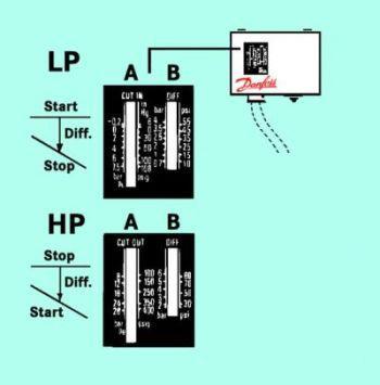
32 REFRIGERATION LAB #5 Objective: To give the student a better understanding of the different type controls within a typical refrigeration system and how they interact. Procedure: 1. The student is to first familiarize his/her-self with the system, its components, valves, controls, and operation. Start the refrigeration system (with evap. #1 Capillary tube on-line, evap. #2 on-line and by-pass the economizer). Allow time for the system to stabilize. (BPR on-line) A. Observe the system s suction pressure, discharge pressure, and evaporator pressure. *L.S. Pressure = *H.S. Pressure = *Evap 1 Pressure = *Evap 2 Pressure = 2. a. Set the LP control to cut out at.5 psi and to cut in at 6 psi Cut out = Cut in - Differential b. Set the HP cut-out to 20 psi higher than the operating pressure with a 40 psi differential. Cut in = Cut out - Differential Once this is set, secure the suction side valve (at the heat interchanger). Watch the pressure gauge and note the pressure at which the compressor shuts down. Cut out Pressure = Next, slowly open the suction side valve and observe the pressure at which the compressor restarts. Page 28 Refrigeration Lab #5
33 Cut in Pressure = 3. For the high side, secure the condenser fan. Next, observe the pressure at which the compressor shuts down. Cut out Pressure = Restart the condenser fan and observe the pressure at which the compressor restarts. Cut in Pressure = 4. For the next procedure, increase the temperature setting for Box 1 till the refrigerant solenoid valve closes. *Temp.(close) = Reset the control to a lower temperature till the solenoid valve reopens. *Temp.(open) = *Temp. Diff. = 5. Calculate the superheat at the heat exchanger inlet and compressor inlet *SH.(Box1 out) = *SH.(Box2 out) = *SH.(HX in) = *SH.(Comp. in) = Calculate the subcooling at the heat exchanger inlet, heat exchanger outlet, and Flow control 1&2. *SC.(HX in) = * SC.(HX out) = * SC.(FC1) = * SC.(FC2) = Refrigeration Lab #5 Page 29
34 Put the economizer on-line. Recalculate the superheat and subcooling *SH.(Box1 out) = *SH.(Box2 out) = *SH.(HX in) = *SH.(Comp. in) = *SC.(HX in) = * SC.(HX out) = * SC.(FC1) = * SC.(FC2) = Decrease the speed of the box 1 fan and recalculate the superheat at evap 1 out. *SH.(Box1 out) = Decrease the speed of the condenser fan and recalculate the subcooling. *SC.(HX in) = * SC.(HX out) = 6. Switch over the flow control on the #1 evap. to the TXV and allow time for the system to stabilize. Adjust the TXV for 5ºF superheat. Once stable, by-pass the BPR and let the system stabilize. Measure the superheat. 7. Switch over the flow control on the #1 evap. To the AEV and allow time for the system to stabilize. Adjust the control for proper superheat. Once stable, place the BPR on line and let the system stabilize. Measure the superheat. Conclusion: You should have a better understanding of refrigeration controls. You should also be able to calculate the cut-out, cut-in and differential for these systems and also know how to make these adjustments. Page 30 Refrigeration Lab #5
35 Refrigeration Lab #5 Page 31
36 Refrigeration STCW Practical OBJECTIVE RULES To assess the student s ability to safely and properly start, operate, and secure a traditional refrigeration system. During this assessment, you should also be able to determine if the system is operating correctly. If the system is not operating correctly, be able to explain the potential problems. You will not be required to repair the system for proper operation. 1. Safety Glasses must be worn at all times during the exam 2. You may ask your examiner up to three (3) questions before the assessment begins but may not ask any questions during. Once you start, the examiner is only there to observe your progress. He/she may ask you questions. 3. Any time you make an error you will be given a strike. Three strikes and you are out! 4. Any single error which may result in injury, failure of the system, or any damage to a component of the system will be an immediate failure. 5. All pressures and saturation temperatures will be taken from the manifold (No charts will be allowed). 6. There is a 15 minute time limit. If you exceed this limit, you fail. PROCESS 1. Check the system over. 2. Connect service gauges 3. Start the refrigeration system 4. Determine whether the system is operating properly 5. Pump system down 6. Secure system 7. Remove and stow gauges and tools. Refrigeration Lab #6
37 Refrigeration Lab Page 33
38 Page 34 Refrigeration Lab
39 Refrigeration Lab Page 35
40 Page 36 Refrigeration Lab
AIR CONDITIONING. Carrier Corporation 2002 Cat. No
 AIR CONDITIONING Carrier Corporation 2002 Cat. No. 020-016 1. This refresher course covers topics contained in the AIR CONDITIONING specialty section of the North American Technician Excellence (NATE)
Section 1: Theory of Heat Unit 3: Refrigeration and Refrigerants
 Section 1: Theory of Heat Unit 3: Refrigeration and Refrigerants Unit Objectives After studying this chapter, you should be able to: Discuss applications for high-, medium-, and low temperature refrigeration.
Some of these procedures need to be performed to conform to requirements of the Clean Air Act.
 Leak Detection, Recovery, Evacuation and Charging Four basic service procedures used to repair and maintain a mechanical refrigeration system are leak detection, evacuation, recovery, and refrigerant charging.
Installation Manual for. Series HWM and Non-ETI HYDRONIC WATER MODULE with SC and SD COMPRESSOR UNITS and R-410 REFRIGERANT
 EarthLinked TXV Kit Installation Manual for Series HWM and Non-ETI HYDRONIC WATER MODULE with SC and SD COMPRESSOR UNITS and R-410 REFRIGERANT CONTENTS PAGE Pre-Installation 3 Hydronic Water Module Conversion
Installation Manual for CCS Cased Coils with SC, SD, SW Compressor Units and R-410A Refrigerant
 EarthLinked TXV Kit Installation Manual for CCS Cased Coils with SC, SD, SW Compressor Units and R-410A Refrigerant CONTENTS PAGE Pre-Installation 3 Cased Coil Conversion 4 System Start-Up 17 TXV CCS-410-KIT
SERVICE BULLETIN A
 1. PLANNING INFORMATION A. Effectivity: Dassault Falcon 10 aircraft which have installed R-134a Upgrade Kit SZ59K-R134 before August 8, 2002. B. Reason: Upgrade kits before August 8, 2002 did not include
Thomas J Kelly. Fundamentals of Refrigeration. Sr. Engineering Instructor Carrier Corporation. August 20, Page number: 1.
 Thomas J Kelly Sr. Engineering Instructor Carrier Corporation August 20, 2003 1 SESSION OBJECTIVES At the conclusion of this session you should be able to: 1. Describe the basics principles of refrigeration
PRESSURE-ENTHALPY CHARTS AND THEIR USE By: Dr. Ralph C. Downing E.I. du Pont de Nemours & Co., Inc. Freon Products Division
 INTRODUCTION PRESSURE-ENTHALPY CHARTS AND THEIR USE The refrigerant in a refrigeration system, regardless of type, is present in two different states. It is present as liquid and as vapor (or gas). During
Condensing Unit Installation and Operating Instructions
 Bulletin WCU_O&I 01 June 2003 Condensing Unit Installation and Operating Instructions WCU Air Cooled Condensing Unit Table of Contents Section 1. Section 2. Section 3. Section 4. Section 5. Section 6.
Installation Manual for ETI AVS Series and NON-ETI Air Handlers with SC or SD Compressor Units and R-410A Refrigerant
 EarthLinked TXV Kit Installation Manual for ETI AVS Series and NON-ETI Air Handlers with SC or SD Compressor Units and R-410A Refrigerant CONTENTS PAGE Pre-Installation 3 Air Handler Conversion 4 System
The Refrigeration Cycle
 Job Sheet 4 The Refrigeration Cycle OBJECTIVES In this job sheet, you will plot the refrigeration cycle on a pressure-enthalpy diagram using pressures and temperatures measured on your training system.
Calhoon MEBA Engineering School. Study Guide for Proficiency Testing Refrigeration
 Calhoon MEBA Engineering School Study Guide for Proficiency Testing Refrigeration 1. To prevent an injury when working with refrigerants, what safety precautions are necessary? 2. When halogens are in
The Refrigeration Cycle
 Job Sheet 4 The Refrigeration Cycle OBJECTIVES In this job sheet, you will plot the refrigeration cycle on a pressure-enthalpy diagram using pressures and temperatures measured on your training system.
HEAT PUMPS. Carrier Corporation GT72-01 Cat. No
 HEAT PUMPS Carrier Corporation 2003 GT72-01 Cat. No. 020-018 1. This refresher course covers topics contained in the HEAT PUMPS specialty section of the North American Technician Excellence (NATE) certification
Energy Use in Refrigeration Systems
 2012 Rocky Mountain ASHRAE Technical Conference Energy Use in Refrigeration Systems PRESENTED BY: Scott Martin, PE, LEED AP BD+C Objectives Understand mechanical refrigeration terms Describe how heat is
SECTION 2 SAFETY, TOOLS & EQUIPMENT, SHOP PRACTICES UNIT 8 SYSTEM EVACUATION
 SECTION 2 SAFETY, TOOLS & EQUIPMENT, SHOP PRACTICES UNIT 8 SYSTEM EVACUATION UNIT OBJECTIVES After studying this unit, the reader should be able to Describe a standing pressure test. Choose a leak detector
Refrigerant Recovery Unit, Model RRU134
 Installation, Operation & Maintenance Manual IOMM RRU134 Group: Refrigerant Effective: December 2000 Supersedes: New Refrigerant Recovery Unit, Model RRU134 1999 McQuay International Table of Contents
EarthLinked SW Series Compressor Unit R-410A Quik-Start Instructions
 EarthLinked SW Series Compressor Unit R-410A Quik-Start Instructions CONTENTS PAGE Pre-Installation 3 Placement & Mechanical Information 4 System Application Options 10 Antifreeze Protection 14 Electrical
To accomplish this, the refrigerant fi tis pumped throughh aclosed looped pipe system.
 Basics Refrigeration is the removal of heat from a material or space, so that it s temperature is lower than that of it s surroundings. When refrigerant absorbs the unwanted heat, this raises the refrigerant
Otherwise, you can continue reading the file on the following pages.
 If you d like to be able to print this file out to study off-line or use on the job, a printable version is available for an administrative fee of $3.97 USD. To download the unlocked file, click here.
B. A. T. Basic Appliance Training
 B. A. T. Basic Appliance Training BASIC REFRIGERATION presented by Phil Whitehead Program Objective The objective of this program is to give you some of the basic elements that are essential to understanding
R.A.S.E.R.S System. Installation Guide
 R.A.S.E.R.S System Installation Guide Contents R.A.S.E.R.S System components... 1 Required components for heating, cooling, and hot water...1 Provided...1 Not provided...2 Optional components...3 R.A.S.E.R.S
SECTION 50 - CAB CLIMATE CONTROL
 AIR CONDITIONING SYSTEM DYNAMIC DESCRIPTION The refrigerant circuit of the air conditioning system contains five major components: Compressor, Condenser, Receiver/Drier, Expansion Valve, and Evaporator.
SERVICING PROCEDURE R-410A LEAK TEST EVACUATION CHARGING. Bard Manufacturing Company, Inc. Bryan, Ohio Manual Page 1 of 11
 SERVICING PROCEDURE R-410A LEAK TEST EVACUATION CHARGING Bard Manufacturing Company, Inc. Bryan, Ohio 43506 Since 1914...Moving ahead, just as planned. Manual No.: 2100-479 Supersedes: NEW File: Volume
OPERATING INSTRUCTIONS
 OPERATING INSTRUCTIONS MODEL LV20 LARGE CAPACITY REFRIGERANT RECOVERY UNIT NATIONAL REFRIGERATION PRODUCTS 985 WHEELER WAY LANGHORNE, PA 19047 (215) 638-8909 FAX (215) 638-9270 R01101 LV20.DOC NRP-OM-LV20
Sporlan Valve Division Parker Hannifan/CIC Group
 www.parker.com/cic Sporlan Valve Division Parker Hannifan/CIC Group Matt McGrath, SW Regional Sales Manager Bob Dolan, Sales Engineer - Atlanta www.parker.com/cic Why Discuss TEVs Today? Expansion Valves
Refrigerant changeover guidelines
 Refrigerant changeover guidelines HCFC R-22 to HFC R-407A/F, R-448A or R-449A for medium and low temperature applications HCFC R-22 to HFC R-407C for high, medium and low temperature applications HCFC
Table of Contents. Service Procedures. Service Procedures. Measuring Superheat (4) Measuring Subcooling (5) Airflow Calculation (6-8)
 Measuring Subcooling (5) Airflow Calculation (6-8)") Table of Contents Refrigeration Cycle Service Procedures Measuring Superheat (4) Measuring Subcooling (5) Airflow Calculation (6-8) Solving Problems Identifying Low System Charge (9-11) Identifying High
Table of Contents Refrigeration Cycle Service Procedures Measuring Superheat (4) Measuring Subcooling (5) Airflow Calculation (6-8) Solving Problems Identifying Low System Charge (9-11) Identifying High
National Maritime Center
 National Maritime Center Providing Credentials to Mariners U.S.C.G. Merchant Marine Exam (Sample Examination) Page 1 of 26 Choose the best answer to the following Multiple Choice Questions. 1. If a condenser
EarthLinked SC Series Compressor Unit R-407C Quik-Start Instructions
 EarthLinked SC Series Compressor Unit R-407C Quik-Start Instructions CONTENTS PAGE Pre-Installation 3 Placement & Mechanical Information 4 System Application Options 11 Desuperheater Kit 15 Antifreeze
For an administrative fee of $9.97, you can get an un-locked, printable version of this book.
 The System Evaluation Manual and Chiller Evaluation Manual have been revised and combined into this new book; the Air Conditioning and Refrigeration System Evaluation Guide. For an administrative fee of
XC13. IMPORTANT Operating pressures of this R 410A unit are higher than pressures in R 22 units. Always use service equipment rated for R410A.
 Service Literature Corp. 0521 L9 Revised 09 2007 XC13 SERIES UNITS XC13 The XC13 is a high efficiency residential split system condensing unit, which features a scroll compressor and R 410A refrigerant.
HEATING, AIR CONDITIONING AND REFRIGERATION TECHNOLOGY COURSE SYLLABUS
 HEATING, AIR CONDITIONING AND REFRIGERATION TECHNOLOGY COURSE SYLLABUS COURSE NUMBER: Hart 1307 COURSE TITLE: Basic Refrigeration Principles CREDITS: # (2 lectures, 3 labs) PREREQUISITE/COREQUISITE: HART
Pressure Enthalpy Charts
 Pressure Enthalpy Charts What is a p-h Diagram? A p-h diagram is a diagram with a vertical axis of absolute pressure and a horizontal axis of specific enthalpy. "Enthalpy is the amount of energy in a substance
a. CFCs. b. HCFCs. c. Pressurized nitrogen. d. Compressed dry air. 17. The state of the refrigerant leaving the condenser of a refrigeration system
 Core 1. Ozone in the stratosphere above the earth consists of: a. Molecules containing 3 oxygen atoms. b. Molecules of 2 oxygen atoms. c. Radioactive particles. d. Pollutants that have risen from ground
ENSPECO Recovery/ Recycle/ Evacuate/ Recharge
 ENSPECO Recovery/ Recycle/ Evacuate/ Recharge RMS 3012 RMS 3034 Approved by UL/SAE to J-1991 R12 Purity Standards Approved by UL/SAE to J-2210 R134 Purity Standards This semi-automatic machine will recover
SECTION 2 SAFETY, TOOLS AND EQUIPMENT, SHOP PRACTICES UNIT 10 SYSTEM CHARGING
 SECTION 2 SAFETY, TOOLS AND EQUIPMENT, SHOP PRACTICES UNIT 10 SYSTEM CHARGING UNIT OBJECTIVES After studying this unit, the reader should be able to Describe how refrigerant is charged into systems in
Condensing Unit Installation and Operating Instructions
 Bulletin ACU_O&I 02 August 2016 Condensing Unit Installation and Operating Instructions ACU Air Cooled Condensers Table of Contents Section 1. General Information... 2 Section 2. Refrigeration Piping...
OPERATION & MAINTENANCE MANUAL AC860
 OPERATION & MAINTENANCE MANUAL AC860 Refrigerant Handling System Manual P/N 035-80913-00 TABLE OF CONTENTS Startup & Safe Operation... 1 Introduction to the AC860... 2 Control Panel... 3 Keypad Functions...
Service Step by Step Trouble-Shooting Check-List
 WARNING: Only Data Aire trained technician or experience technicians should be working on Data Aire Equipment. Protect yourself at all times and work safe. Date: Dates at the job site: From: to Job#: Serial#:
HP13 WARNING WARNING. Service Literature HP13 SERIES UNITS
 Service Literature Corp. 0610 L1 Revised 07 2006 HP13 SERIES UNITS HP13 The HP13 is a high efficiency residential split system heat pump unit, which features a scroll compressor. HP13 units are available
INSTALLATION MODULE XARIOS RANGE. UTC Climate, Controls & Security PROPRIETARY Rev B 29th mai 2013
 INSTALLATION MODULE XARIOS RANGE 1 TABLE OF CONTENT GENERAL INSTALLATION RECOMMENDATION CONDENSOR INSTALLATION 3 CONDENSOR: PREPARATION 4 REFRIGERATION HOSES PREPARATION 5 HOSES: MOUNTING 6 BOX: HARNESS
The Essentials Of Working With R-410A
 The Essentials Of Working With R-410A By Norm Christopherson Several major manufacturers are producing comfort air conditioning equipment using refrigerant 410A. The trend towards the use of 410A continues
EarthLinked SCW Series Compressor Unit R-410A Quik-Start Instructions
 EarthLinked SCW Series Compressor Unit R-410A Quik-Start Instructions CONTENTS PAGE Pre-Installation 3 Placement & Mechanical Information 6 System Application Options 12 Antifreeze Protection 13 Electrical
A Treatise on Liquid Subcooling
 A Treatise on Liquid Subcooling While the subject of this article is Liquid Refrigerant Subcooling, its affect on the operation of the thermostatic expansion valve (TEV), and ultimately on system performance
Warm Case Troubleshooting Guide 9/18/2014
 Introduction Warm cases can be caused by various problems which require thorough troubleshooting. Begin the investigation with questions to store personnel asking for information such as when the last
10/4/2013. The Changing State of Refrigerants
 10/4/2013 The Changing State of Refrigerants Refrigerant Chemistry CFC = Chlorofluorocarbon Rapid phase-out Stopped U.S. production in 1996 R-11, R-12, R-113, R-114, R-500, R-502 HCFC = Hydrochlorofluorocarbon
SECTION REFRIGERATION EQUIPMENT. A. Section Includes: Refrigeration equipment for insulated cold storage rooms including necessary accessories.
 SECTION 15650 REFRIGERATION EQUIPMENT PART 1 GENERAL 1.01 SUMMARY A. Section Includes: Refrigeration equipment for insulated cold storage rooms including necessary accessories. B. Related Section: 1. 11400
13ACX. IMPORTANT Operating pressures of this R 410A unit are higher than pressures in R 22 units. Always use service equipment rated for R 410A.
 Service Literature Corp. 0612 L2 Revised 07 2006 13ACX SERIES UNITS 13ACX The 13ACX is a high efficiency residential split system condensing unit, which features a scroll compressor and designed for R
Residential Piping and Long Line Guideline
 AC / HP R-410A Refrigerant Systems Single-Stage, Two-Stage and Variable Speed Models Residential Piping and Long Line Guideline TABLE OF CONTENTS Safety Considerations... 2 Definitions... 2 Introduction...
OPERATION & MAINTENANCE MANUAL RHS680
 OPERATION & MAINTENANCE MANUAL RHS680 Refrigerant Handling System 4075 East Market Street York, PA 17402 800-468-2321 tech@rtitech.com Manual P/N 035-80740-00 (Rev 1- May 22, 2001) TABLE OF CONTENTS Startup
RecoverX Oil-Filled Hermetic Refrigerant Recovery System. Operation and Maintenance Manual
 RecoverX Oil-Filled Hermetic Refrigerant Recovery System Operation and Maintenance Manual Table of Contents Page General Safety Instructions 2-3 System Overview 3 Operating Guide 4 Restart Procedure 4
Operation and Maintenance Manual
 Warranty Information Ritchie Engineering guarantees YELLOW JACKET products to be free of defective material and workmanship which could affect the life of the product when used for the purpose for which
Case 15 Refrigeration System for Chemical Fertilizer Plant Ammonia Storage
 Case 15 Refrigeration System for Chemical Fertilizer Plant Ammonia Storage Copy Right By: Thomas T.S. Wan ) Dec. 28, 2012 All Rights Reserved Case Background: Ammonia is one of the important elements to
ariazone 601HD Refrigerant Recovery & Recycling Unit User's manual
 ariazone 601HD Refrigerant Recovery & Recycling Unit User's manual Model: Ariazone 601 HD Serial No: 1 1. SAFETY FIRST! Important safety information's - Read this user manual carefully before operating
Class 1: Basic Refrigera0on Cycle. October 7 & 9, 2014
 Class 1: Basic Refrigera0on Cycle October 7 & 9, 2014 Refrigeration Cycle 4 key components needed in a basic refrigera0on cycle: 1. Compressor 2. Condenser 3. Evaporator 4. Metering Device Compressor Compressor
WineZone Ceiling Mount Ductless Split 15
 WineZone Ceiling Mount Ductless Split 15 Requires an HVAC technician to install and charge with R-22 refrigerant. Easy to install. Unit plugs into wall outlet. Industrial grade unit for longer life. Indoor
Corp L9 Revised HS27 SERIES UNITS SPECIFICATIONS. Model No. HS HS HS HS27-042
 Service Literature Corp. 9619 L9 Revised 08 2004 HS27 SERIES UNITS HS27 The HS27 is a 14 SEER high efficiency residential split system condensing unit which features a scroll compressor. It operates much
Publication # RD-0003-E Rev 1, 10/17 SERVICE GUIDELINES HCFC R22 TO HFC REFRIGERANT BLENDS
 Publication # RD-0003-E Rev 1, 10/17 SERVICE GUIDELINES HCFC R22 TO HFC REFRIGERANT BLENDS Refrigerant R22 is widely used for residential and commercial air conditioning, as well as commercial refrigeration
Vacuum Gauge. Measures lower-than-atmospheric pressure Digital scales. microns psi in. Hg millibars pascals torr millitorr
 Vacuum Gauge Measures lower-than-atmospheric pressure Digital scales microns psi in. Hg millibars pascals torr millitorr (Sealed Unit Parts Co., Inc.) Compound Gauge Measures pressure and vacuum Low-side
OPER LV Wheeler Way
 OPER RATING INSTRUCTIONS LV5 REFRIGERANT RECOVERY UNIT NATIONAL REFRIGERATION PRODUCTS 985 Wheeler Way Langhorne, PA 19047 Ph:(215) 638-8909 9 info@ @nrproducts.com LV5.DOC 9.17.2018 MODEL LV5 REFRIGERANT
Instructors: Contact information. Don Reynolds Doug McGee Factory Tech Support
 Contact information Instructors: Don Reynolds 616-560-9903 Doug McGee 517-294-3932 Factory Tech Support 888-593-9988 Product Improvements for 2017 Todays Objectives Job Site Information Sheets Low Ambient
HEATING, AIR CONDITIONING & REFRIGERATION TECHNOLOGY DEPARTMENT COURSE SYLLABUS
 ARCHITECTURE, CONSTRUCTION & MANUFACTURING TECHNOLOGIES DIVISION HEATING, AIR CONDITIONING & REFRIGERATION TECHNOLOGY DEPARTMENT COURSE SYLLABUS COURSE NUMBER: Hart 1341 COURSE TITLE: RESIDENTIAL AIR CONDITIONING
PL Series Premier Indoor Plenum Coils
 IM-PLC-0667392-04 April 2016 PL Series Premier Indoor Plenum Coils Installation Instructions GENERAL ADP evaporator coils are designed for use with condensing units or heat pump units. These instructions
Refrigeration Training System
 3401-20 Refrigeration Training System LabVolt Series Datasheet Festo Didactic en 120 V - 60 Hz 04/2018 Table of Contents General Description 2 Topic Coverage 2 Features & Benefits 2 List of Manuals 3 Table
G Series. G Series Air Coils Installation ti Manual ENCASED/UNCASED AIR COILS. Geothermal/Water Source Heat Pumps R-410A Refrigerant 2-5 Ton
 G Series ENCASED/UNCASED AIR COILS Geothermal/Water Source Heat Pumps R-410A Refrigerant 2- Ton Dimensional Data G Series Air Coils Installation ti Manual Installation Information Maintenance IM1018AG1
TECHNICAL GUIDE DESCRIPTION SPLIT-SYSTEM AIR-COOLED CONDENSING UNITS. HA300, HB360, HB480 & HB thru 50 NOMINAL TONS (50 Hz)
") DESCRIPTION These units are completely assembled, piped and wired at the factory to provide one-piece shipment and rigging. Each unit is pressurized with a holding charge of refrigerant-22 for storage
DESCRIPTION These units are completely assembled, piped and wired at the factory to provide one-piece shipment and rigging. Each unit is pressurized with a holding charge of refrigerant-22 for storage
CS/CD/CP AIR COOLED CONDENSING UNITS (P/N E207120C R2)
") CS*/CD*/CP* Series Air Cooled Condensing Units Operating and Installation Manual CS/CD/CP AIR COOLED CONDENSING UNITS (P/N E207120C R2) TABLE OF CONTENTS I. Receipt of Equipment 2 II. Piping...4 III. System
CS*/CD*/CP* Series Air Cooled Condensing Units Operating and Installation Manual CS/CD/CP AIR COOLED CONDENSING UNITS (P/N E207120C R2) TABLE OF CONTENTS I. Receipt of Equipment 2 II. Piping...4 III. System
Eclipse Technical Training CME686 CME810 CP686 CP886 CP1086
 Eclipse Technical Training CME686 CME810 CP686 CP886 CP1086 In This Presentation What Eclipse is Components and their functions Installation Operation Maintenance Service Diagnosis The Eclipse System The
R-290 SERVICE MANUAL SWF MODELS. Principals and Best Practices for servicing HC refrigeration equipment
 R-290 SERVICE MANUAL SWF MODELS Principals and Best Practices for servicing HC refrigeration equipment 1-800-523-7138 SCAN this code to download manual Service Hours: Monday to Friday, 8 am to 5 pm EST
Technical Development Program. COMMERCIAL HVAC PACKAGED EQUIPMENT Split Systems PRESENTED BY: Ray Chow Sigler
 Technical Development Program COMMERCIAL HVAC PACKAGED EQUIPMENT Split Systems PRESENTED BY: Ray Chow Sigler Menu Section 1 Section 2 Section 3 Section 4 Section 5 Section 6 Section 7 Introduction System
13ACX. IMPORTANT Operating pressures of this R 410A unit are higher than pressures in R 22 units. Always use service equipment rated for R 410A.
 Service Literature Corp. 0612 L2 Revised 06 2007 13ACX SERIES UNITS 13ACX The 13ACX is a high efficiency residential split system condensing unit, which features a scroll compressor and designed for R
Reference Document RD-0007-E GUIDELINES FOR THE UTILIZATION OF R-404A R-452A. Page 1 of Tecumseh Products Company LLC. All rights reserved.
 GUIDELINES FOR THE UTILIZATION OF R-404A R-452A Page 1 of 10 GUIDELINES FOR THE UTILIZATION OF R-404A AND R-452A For many years, R-404A has emerged as the industry's major choice as an alternative refrigerant
Use this Construction/HVAC Glossary to answer the questions below.
 www.garyklinka.com Page 1 of 21 Instructions: 1. Print these pages. 2. Circle the correct answers and transfer to the answer sheet on the second last page. 3. Page down to the last page for the verification
Installation Manual BCS 1000/1500
 Installation Manual BCS 1000/1500 Supplies Needed for Installation 1. Double insulated refrigerant line set. 2. 1/4 copper water supply 3. 1/4 condensate vinyl drain tube/tube clamps 4. Provide 120V 15A
OPERATING INSTRUCTIONS
 OPERATING INSTRUCTIONS MODEL LV8 COMMERCIAL REFRIGERANT RECOVERY UNIT NATIONAL REFRIGERATION PRODUCTS 985 WHEELER WAY LANGHORNE, PA 19047 (215) 638-8909 FAX (215) 638-9270 A01001 7/11/96 NRP-OM-LV8 7/96
Refrigerant Changeover Guidelines HFC R-404A/R-407A/C/F to R-448A/R-449A. Leading the Industry with Environmentally Responsible Refrigerant Solutions
 Refrigerant Changeover Guidelines HFC R-404A/R-407A/C/F to R-448A/R-449A Leading the Industry with Environmentally Responsible Refrigerant Solutions Emerson Climate Technologies, Inc. does not advocate
Instruction Manual DIGITAL MANIFOLD FOR HVAC/R SYSTEMS
 English Instruction Manual DIGITAL MANIFOLD FOR HVAC/R SYSTEMS 99 Washington Street Melrose, MA 02176 Phone 781-665-1400 Toll Free 1-800-517-8431 Visit us at www.testequipmentdepot.com Instruction Manual
ENERGY EFFICIENCY PERFORMANCE SAVINGS SERVICE MANUAL R-290
 hydrocarbon ENERGY EFFICIENCY PERFORMANCE SAVINGS SERVICE MANUAL R-290 974280 INDEX Why R-290... 1 Best Alternative... 2-3 FAQ... 4-7 Labeling... 8-10 The Difference in R-290 vs. R-134a/R-404A... 11-17
Ariazone 601HD Refrigerant Recovery&Recycling unit
 Automotive Air-Conditioning Service Equipment Ariazone 601HD Refrigerant Recovery&Recycling unit OPERATOR MANUAL 1 1. SAFETY FIRST! Important safety information's - Read this user manual carefully before
Often fellow technicians, co-workers and field personnel CHARGE REFRIGERANT DETERMINING PROPER SYSTEM
 Image courtesy of Mastercool. DETERMINING PROPER SYSTEM REFRIGERANT CHARGE Troubleshooting refrigerant system issues is one of the toughest jobs HVACR technicians will ever face. BY RICH PERROTTA A wireless
HEATING AND AIR CONDITIONING
 WJ HEATING AND AIR CONDITIONING 24-1 HEATING AND AIR CONDITIONING TABLE OF CONTENTS page SERVICE PROCEDURES REFRIGERANT OIL LEVEL...1 REFRIGERANT RECOVERY....1 REFRIGERANT SYSTEM CHARGE...1 REFRIGERANT
SECTION 7 AIR CONDITIONING (COOLING) UNIT 41 TROUBLESHOOTING
 UNIT 41 TROUBLESHOOTING") SECTION 7 AIR CONDITIONING (COOLING) UNIT 41 TROUBLESHOOTING UNIT OBJECTIVES After studying this unit, the reader should be able to Select the correct instruments for checking an air conditioning unit
SECTION 7 AIR CONDITIONING (COOLING) UNIT 41 TROUBLESHOOTING UNIT OBJECTIVES After studying this unit, the reader should be able to Select the correct instruments for checking an air conditioning unit
BASIC HEAT PUMP THEORY By: Lloyd A. Mullen By: Lloyd G. Williams Service Department, York Division, Borg-Warner Corporation
 INTRODUCTION In recent years air conditioning industry technology has advanced rapidly. An important byproduct of this growth has been development of the heat pump. Altogether too much mystery has surrounded
Refrigerant Installation Quick Reference Guide
 Refrigerant Installation Quick Reference Guide To be used only by experienced and licensed refrigeration technicians Preface: This project objective is to replace existing CFC or HCFC refrigerants with
YCIV Hz & Hz
 YCIV 0590-1500 50Hz & 0157-0397 60Hz Start-up Checklist SERVICE POLICY & PROCEDURES Supersedes: Nothing Form 201.23-CL1 (309) Commissioning PREPARATION Commissioning of this unit should only be carried
a. CFCs. b. HCFCs. c. Pressurized nitrogen. d. Compressed dry air. 17. The state of the refrigerant leaving the condenser of a refrigeration system
 Core 1. Ozone in the stratosphere above the earth consists of: a. Molecules containing 3 oxygen atoms. b. Molecules of 2 oxygen atoms. c. Radioactive particles. d. Pollutants that have risen from ground
Session: HVAC 101 HVAC 101. Steve Sain Sain Engineering Associates, Inc. August 9, Rhode Island Convention Center Providence, Rhode Island
 Session: HVAC 101 HVAC 101 Steve Sain Sain Engineering Associates, Inc. August 9, 2016 Rhode Island Convention Center Providence, Rhode Island Why? 2 Acknowledgements 3 Disclaimer I m gonna shoot down
HSXA16 WARNING. WARNING R 410A refrigerant can be harmful if it is inhaled. R 410A refrigerant must be used and recovered responsibly.
 Service Literature Corp. 0507 L2 Revised 07 2006 HSXA16 HSXA16 SERIES UNITS The HSXA16 is a high efficiency residential split system condensing unit, which features a two stage scroll compressor and R
TWO- AND THREE-STAGE CASCADE REFRIGERATION SYSTEM By: Paul B. Reed
 INTRODUCTION Service Application Manual Mechanical refrigerating systems in most common use fall into three classes as far as the temperatures of the evaporators are concerned: 1. High temperatures, with
LENNDX INSTALLATION INSTRUCTIONS. IIlIIIIIIIIIIIIIIIIIIIIIIIHI A, WARNING A, WARNING WARNING RETAIN THESE INSTRUCTIONS FOR FUTURE REFERENCE
 LENNDX,1,_2000 Lennox Industries Inc. Dallas, Texas, USA INSTALLATION INSTRUCTIONS HS40 S UNITS CONDENSING UNITS lie_ :.) Technical 504,186M.LU_ Publications 11/2002 Lithe U.S.A. Supersedes 4/2000 HS40
AIM: TO STUDY THE PERFORMANCE OF THE DOMESTIC REFRIGERATION RIG.
 AIM: TO STUDY THE PERFORMANCE OF THE DOMESTIC REFRIGERATION RIG. Page1 CONTENT: 1. Product Description 2. Product Specifications 3. Operating Procedure 4. Observation Table 5. Calculations 6. Result Page2
System Considerations for Refrigerant Blends with Temperature Glide
 System Considerations for Refrigerant Blends with Temperature Glide Theory and Practical Retrofit Guidance Table of Contents 1 2 3 4 5 Blend and Glide Basics... 3 1.1 Superheat and Subcooling of Refrigerant
XC16. IMPORTANT Operating pressures of this R 410A unit are higher than pressures in R 22 units. Always use service equipment rated for R410A.
 Service Literature Corp. 0625 L5 Revised 07 2006 XC16 SERIES UNITS XC16 The XC16 is a high efficiency residential split system condensing unit, which features a two speed scroll compressor and R 410A refrigerant.
HSXA15 HSXB15. IMPORTANT Operating pressures of this R410A unit are higher than pressures in R22 units. Always use service equipment rated for R410A.
 Service Literature Corp. 0128 L12 Revised 10 2004 HSXB15 & HSXB15 SERIES UNITS The and HSXB15 are high efficiency residential split system condensing units, which features a scroll compressor and R410A
SECTION 8 AIR SOURCE HEAT PUMPS UNIT 43 AIR SOURCE HEAT PUMPS
 SECTION 8 AIR SOURCE HEAT PUMPS UNIT 43 AIR SOURCE HEAT PUMPS UNIT OBJECTIVES After studying this unit, the reader should be able to Describe the operation of reverse-cycle refrigeration (heat pumps) Explain
Installation 50% Service 20% Components 20% Applied Knowledge 10%
 LIGHT COMMERCIAL REFRIGERATION INSTALLATION CERTIFICATION Certification Information Scope - Tests a candidate's knowledge of the installation, service, maintenance, and repair of Light Commercial Refrigeration
TRS21 IGNITION PROOF SERIES
 TRS21 IGNITION PROOF SERIES 2 Cylinder Commercial Recovery Machine OWNER S MANUAL (English) Français, Español, Deutsch and latest updates: www.cpsproducts.com Series: TRS21A, TRS21E TO BE OPERATED BY QUALIFIED
14. The center port of the manifold is used for evacuation, charging and refrigerant recovery.
 HET- 190 ESL Support page 1 CORE Basic Refrigeration Circuit 1. Liquid refrigerant boils in the evaporator. Heat is absorbed. The heat energy absorbed converts refrigerant liquid into vapor. 2. Refrigerant
APPLICATION & SERVICE GUIDE
 APPLICATION & SERVICE GUIDE HFC Refrigerant R410a Used In GeoMax2 Geothermal Heat Pump Systems Although the bulk of this manual is information regarding R410a, R407c will also be discussed for purposes