SERVICE MANUAL. Inverter Wall Mounted Single Split MODELS SM-5WM-Y-EU-A3
|
|
|
- Chad Thomas
- 5 years ago
- Views:
Transcription


1 SERVICE MANUAL Inverter Wall Mounted Single Split MODELS FTXN25/35/50/60L FTXN25/35/50/60M FTXK25/35/50/60A FTXN25/35/50/60N FTXC25/35/50/60A FTXB50/60A FTXB50/60B FTXB50/60C ATXN25/35/50/60L ATXN25/35/50/60M ATXN25/35/50/60N ATXB50/60C RXN25/35/50/60L RXN25/35/50/60M RXK25/35/50/60A RXN25/35/50/60N RXC25/35/50/60A RXB50/60A RXB50/60B RXB50/60C ARXN25/35/50/60L ARXN25/35/50/60M ARXN25/35/50/60N ARXB50/60C dd SM-5WM-Y-EU-A3
2
3 Table of Contents Table of Contents 1.0 Inverter Single Split Product line-up Printed Circuit board (PCB) connector wiring diagram Piping Length & Elevation Function & Control Temperature Control Cooling and Heating Mode Operation Fan Mode Auto Mode Cold Draft Prevention Sleep Mode Quiet Function Eco+ Function ID-OD Communication Thermistors in RXN,RXB,RXC,ARXN,ARXB Minimum Off Time Control Auto Restart Auto Random Restart Four Way Valve Control Outdoor Fan Control Rotation Regulating Functions Defrost Cycle Indoor Coil Freeze Prevention High Pressure Protection Discharge Pipe Temperature Control Oil Recovery Control (Applicable for ARXN,RXN50/60L) Overall Current Control Service Diagnosis Error Indication from Indoor Error code retrieved by handset Error Indication from Outdoor Error code description for Inverter...36
4 Table of Contents 4.0 Wiring Connection Refrigerant Diagram Appendix A...72 ii
5 Table of Contents Safety Cautions Caution and warnings Be sure to read the following safety cautions before conducting repair work. The caution items are classified into Warning and Caution. The Warning items are especially important since they can lead to death or serious injury if they are not followed closely. The Caution items can also lead to serious accidents under some conditions if they are not followed. Therefore, be sure to observe all the safety caution items described below. About the pictograms This symbol indicates an item for which caution must be exercised. The pictogram shows the item to which attention must be paid. This symbol indicates a prohibited action. The prohibited item or action is shown inside or near the symbol. This symbol indicates an action that must be taken, or an instruction. The instruction is shown inside or near the symbol. After the repair work is complete, be sure to conduct a test operation to ensure that the equipment operates normally, and explain the cautions for operating the product to the customer. Caution in Repair Warning Be sure to disconnect the power cable plug from the plug socket before disassembling the equipment for a repair. Working on the equipment that is connected to a power supply can cause an electrical shock. If it is necessary to supply power to the equipment to conduct the repair or inspecting the circuits, do not touch any electrically charged sections of the equipment. If the refrigerant gas discharges during the repair work, do not touch the discharging refrigerant gas. The refrigerant gas can cause frostbite. When disconnecting the suction or discharge pipe of the compressor at the welded section, release the refrigerant gas completely at a well-ventilated place first. If there is a gas remaining inside the compressor, the refrigerant gas or refrigerating machine oil discharges when the pipe is disconnected, and it can cause injury. If the refrigerant gas leaks during the repair work, ventilate the area. The refrigerant gas can generate toxic gases when it contacts flames. The step-up capacitor supplies high-voltage electricity to the electrical components of the outdoor unit. Be sure to discharge the capacitor completely before conducting repair work. A charged capacitor can cause an electrical shock. Do not start or stop the air conditioner operation by plugging or unplugging the power cable plug. Plugging or unplugging the power cable plug to operate the equipment can cause an electrical shock or fire.
6 Table of Contents Caution Do not repair the electrical components with wet hands. Working on the equipment with wet hands can cause an electrical shock. Do not clean the air conditioner by splashing water. Washing the unit with water can cause an electrical shock. Be sure to provide the grounding when repairing the equipment in a humid or wet place, to avoid electrical shocks. Be sure to turn off the power switch and unplug the power cable when cleaning the equipment. The internal fan rotates at a high speed, and cause injury. Do not tilt the unit when removing it. The water inside the unit can spill and wet the furniture and floor. Be sure to check that the refrigerating cycle section has cooled down sufficiently before conducting repair work. Working on the unit when the refrigerating cycle section is hot can cause burns. Use the welder in a well-ventilated place. Using the welder in an enclosed room can cause oxygen deficiency. iv
7 Table of Contents Cautions Regarding Products after Repair Warning Be sure to use parts listed in the service parts list of the applicable model and appropriate tools to conduct repair work. Never attempt to modify the equipment. The use of inappropriate parts or tools can cause an electrical shock, excessive heat generation or fire. When relocating the equipment, make sure that the new installation site has sufficient strength to withstand the weight of the equipment. If the installation site does not have sufficient strength and if the installation work is not conducted securely, the equipment can fall and cause injury. Be sure to install the product correctly by using the provided standard installation frame. Incorrect use of the installation frame and improper installation can cause the equipment to fall, resulting in injury. Be sure to install the product securely in the installation frame mounted on a window frame. If the unit is not securely mounted, it can fall and cause injury. For integral units only For integral units only Be sure to use an exclusive power circuit for the equipment, and follow the technical standards related to the electrical equipment, the internal wiring regulations and the instruction manual for installation when conducting electrical work. Insufficient power circuit capacity and improper electrical work can cause an electrical shock or fire. Be sure to use the specified cable to connect between the indoor and outdoor units. Make the connections securely and route the cable properly so that there is no force pulling the cable at the connection terminals. Improper connections can cause excessive heat generation or fire. When connecting the cable between the indoor and outdoor units, make sure that the terminal cover does not lift off or dismount because of the cable. If the cover is not mounted properly, the terminal connection section can cause an electrical shock, excessive heat generation or fire. Do not damage or modify the power cable. Damaged or modified power cable can cause an electrical shock or fire. Placing heavy items on the power cable, and heating or pulling the power cable can damage the cable. Do not mix air or gas other than the specified refrigerant (R-410A) in the refrigerant system. If air enters the refrigerating system, an excessively high pressure results, causing equipment damage and injury. If the refrigerant gas leaks, be sure to locate the leak and repair it before charging the refrigerant. After charging refrigerant, make sure that there is no refrigerant leak. If the leak cannot be located and the repair work must be stopped, be sure to perform pump-down and close the service valve, to prevent the refrigerant gas from leaking into the room. The refrigerant gas itself is harmless, but it can generate toxic gases when it contacts flames, such as fan and other heaters, stoves and ranges. When replacing the coin battery in the remote controller, be sure to disposed of the old battery to prevent children from swallowing it. If a child swallows the coin battery, see a doctor immediately.
8 Table of Contents Caution Installation of a leakage breaker is necessary in some cases depending on the conditions of the installation site, to prevent electrical shocks. Do not install the equipment in a place where there is a possibility of combustible gas leaks. If a combustible gas leaks and remains around the unit, it can cause a fire. Be sure to install the packing and seal on the installation frame properly. If the packing and seal are not installed properly, water can enter the room and wet the furniture and floor. Inspection after Repair Warning Check to make sure that the power cable plug is not dirty or loose, then insert the plug into a power outlet all the way. If the plug has dust or loose connection, it can cause an electrical shock or fire. If the power cable and lead wires have scratches or deteriorated, be sure to replace them. Damaged cable and wires can cause an electrical shock,excessive heat generation or fire. Do not use a joined power cable or extension cable, or share the same power outlet with other electrical appliances, since it can cause an electrical shock, excessive heat generation or fire. Caution Check to see if the parts and wires are mounted and connected properly, and if the connections at the soldered or crimped terminals are secure. Improper installation and connections can cause excessive heat generation, fire or an electrical shock. If the installation platform or frame has corroded, replace it. Corroded installation platform or frame can cause the unit to fall, resulting in injury. Check the grounding, and repair it if the equipment is not properly grounded. Improper grounding can cause an electrical shock. Be sure to measure the insulation resistance after the repair, and make sure that the resistance is 1 Mohm or higher. Faulty insulation can cause an electrical shock. Be sure to check the drainage of the indoor unit after the repair. Faulty drainage can cause the water to enter the room and wet the furniture and floor. vi
9 Inverter Single Split 1.0 Inverter Single Split 1.1 Product line-up Indoor Unit Classification menclature Handset PCB Air Purification Marking Others BRC52A61 BRC52B63 W_2_03C W_2_03D W_2_03E W_2_03E_M W_2_04A W_2_04B Saranet Filter Titanium Apatite CE GOST EAC Auto Restart FTXN25/35LV1B X X X X X X X FTXN50/60LV1B X X X X X X X ATXN25/35LV1B X X X X X ATXN50/60LV1B X X X X X FTXB50/60AV1B X X X X X FTXB50/60BV1B X X X X X FTXN25/35MV1 X X X X X X X FTXN50/60MV1 X X X X X X X FTXN25/35MV1B X X X X X X X FTXN50/60MV1B X X X X X X X FTXN25/35MV1B9 X X X X X FTXN50/60MV1B9 X X X X X ATXN25/35MV1B X X X X X ATXN50/60MV1B X X X X X ATXN25/35MV1B7 X X X X X X ATXN50/60MV1B7 X X X X X X ATXN25/35MV16 X X X X X X ATXN50/60MV16 X X X X X X FTXK25/35AV1BW X X X X X X FTXK50/60AV1BW X X X X X X FTXK25/35AV1BS X X X X X X FTXK50/60AV1BS X X X X X X FTXN25/35NV1B X X X X X X FTXN50/60NV1B X X X X X X 1
10 Inverter Single Split Indoor Unit Classification menclature Handset PCB Air Purification Marking Others BRC52A61 BRC52B63 W_2_03C W_2_03D W_2_03E W_2_03E_M W_2_04A W_2_04B Saranet Filter Titanium Apatite CE GOST EAC Auto Restart ATXN25/35NV1B X X X X X X ATXN50/60NV1B X X X X X X ATXN25/35NV1B9 X X X X X X ATXN50/60NV1B9 X X X X X X ATXN25/35NV1B7 X X X X X ATXN50/60NV1B7 X X X X X FTXB50/60CV1B X X X X X X X ATXB50/60CV1B X X X X X X FTXC25/35AV1B X X X X X X FTXC50/60AV1B X X X X X X 2
11 Inverter Single Split Outdoor Unit Classification PCB Refrigerant Control Fin Compressor Marking Others menclature OYL Board DKR Board EXV Hydrophilic (Blue) Hydrophilic (Gold) DC Inverter Swing CE GOST EAC Drain Elbow RXN25/35LV1B9 X X X X X X X RXN50/60LV1B9 X X X X X X X ARXN25/35LV1B X X X X X X ARXN50/60LV1B X X X X X X RXB50/60AV1B X X X X X X RXB50/60BV1B X X X X X X RXN25/35MV1 X X X X X X X RXN50/60MV1 X X X X X X X RXN25/35MV1B X X X X X X X RXN50/60MV1B X X X X X X X RXN25/35MV1B9 X X X X X X RXN50/60MV1B9 X X X X X X ARXN25/35MV1B X X X X X X ARXN50/60MV1B X X X X X X ARXN25/35MV1B7 X X X X X X X ARXN50/60MV1B7 X X X X X X X ARXN25/35MV16 X X X X X X ARXN50/60MV16 X X X X X X RXK25/35AV1B X X X X X X X RXK50/60AV1B X X X X X X X RXN25/35NV1B X X X X X X RXN50/60NV1B X X X X X X ARXN25/35NV1B X X X X X X ARXN50/60NV1B X X X X X X ARXN25/35NV1B9 X X X X X X ARXN50/60NV1B9 X X X X X X RXB50/60CV1B X X X X X X X ARXB50/60CV1B X X X X X X RXC25/35AV1B X X X X X X RXC50/60AV1B X X X X X X 3
12 Inverter Single Split 1.2 Printed Circuit board (PCB) connector wiring diagram Indoor PCB: FTXN25/35L, FTXN25/35MV1, FTXN25/35MV1B9, ATXN25/35L, ATXN25/35MV1B, ATXN25/35MV1B Main PCB: W_2_03C Item Indication on PCB Description 1 A1 Connector for fan motor 2 A2 Connector for swing motor 3 A3 Connector for fan motor feedback 4 A4 Fuse 5 A5 Varistor 6 A6 Connector for wired handset 7 A7 Connector for signal receiver PCB 8 A8 Connector for heat exchanger thermistor A1 A2 A3 A4 A5 A6 A7 A8 4
13 Inverter Single Split Signal board Item Indication on PCB Description 1 A1 Operational LED 2 A2 Connector for Control PCB 3 A3 Handset signal receiver 4 A4 Operation ON/OFF switch 5 A5 Buzzer Applicable Model : FTXN25/35L, FTXN25/35MV1, FTXN25/35MV1B9, ATXN25/35L, ATXN25/35MV1B, ATXN25/35MV1B7 5
14 Inverter Single Split Indoor PCB: FTXN25/35MV1B, FTXN25/35N, FTXK25/35A, FTXC25/35A, ATXN25/35MV16, ATXN25/35N Main PCB: W_2_03D ; W_2_03E ; W_2_03E_M Item Indication on PCB Description 1 A1 Connector for fan motor 2 A2 Connector for swing motor 3 A3 Connector for fan motor feedback 4 A4 Fuse 5 A5 Varistor 6 A6 Connector for wired handset 7 A7 Connector for signal receiver PCB 8 A8 Connector for heat exchanger thermistor A1 A2 A3 A5 A4 A7 A6 A8 6
15 Inverter Single Split Signal board Item Indication on PCB Description 1 A1 Operational LED 2 A2 Connector for Control PCB 3 A3 Handset signal receiver 4 A4 Operation ON/OFF switch 5 A5 Buzzer A1 A2 A3 A5 A4 Applicable Model : FTXK25/35A Applicable Model : FTXN25/35MV1B, FTXN25/35N, FTXC25/35A, ATXN25/35MV16, ATXN25/35N 7
16 Inverter Single Split Indoor PCB: FTXB50/60A, FTXB50/60B, FTXB50/60C, FTXN50/60L, FTXN50/60M, FTXN50/60N, FTXK50/60A, FTXC50/60A, ATXB50/60C, ATXN50/60L, ATXN50/60M, ATXN50/60N Main PCB: W_2_04A ; W_2_04B Item Indication on PCB Description 1 A1 Connector for fan motor 2 A2 Connector for swing motor 3 A3 Connector for fan motor feedback 4 A4 Fuse 5 A5 Varistor 6 A6 Connector for wired handset 7 A7 Connector for signal receiver PCB 8
17 Inverter Single Split Signal board Item Indication on PCB Description 1 A1 Operational LED 2 A2 Connector for Control PCB 3 A3 Handset signal receiver 4 A4 Operation ON/OFF switch 5 A5 Buzzer A1 A2 A3 A5 A4 Applicable Model : FTXK50/60A Applicable Model : FTXB50/60A, FTXB50/60B, FTXB50/60C, FTXN50/60L, FTXN50/60M, FTXN50/60N, FTXC50/60A ATXB50/60C, ATXN50/60L, ATXN50/60M, ATXN50/60N 9

18 Inverter Single Split Outdoor PCB: RXN25/35N, RXK25/35A, RXC25/35A, ARXN25/35MV1B7, ARXN25/35MV16, ARXN25/35N Main PCB Item Indication on PCB Description 1 S11 Connector for S10 on main PCB 2 HL1, HN1, S Connector for terminal board 3 E1, E2 Terminal for earth wire 4 HL2, HN2 Connector for HL3 HN3 on main PCB 5 HL4, HN4 Connector for S12 on main PCB 6 FU1 Fuse (3.15A, 250V) 7 FU3 Fuse (30A, 250V) 8 V2, V3 Varistor 10
 3 V2, V3 Varistor 11")
19 Inverter Single Split Outdoor PCB: RXN25/35L, RXN25/35MV1, RXN25/35MV1B, RXN25/35MV1B9, ARXN25/35L, ARXN25/35MV1B Filter PCB Item Indication on PCB Description 1 S11 Connector for indoor PCB 2 FU3 Fuse (20A) 3 V2, V3 Varistor 11

20 Inverter Single Split Main PCB Item Indication on PCB Description 1 S10 Connector for filter PCB 2 S20 Connector for electronic expansion valve coil 3 S40 Connector for overload protector 4 S70 Connector for fan motor 5 S80 Connector for four way valve coil 6 S90 Connector for thermistors (outdoor temperature, outdoor heat exchanger, discharge pipe) 7 HL3, HN3 Connector for filter PCB 8 FU1, FU2 Fuse (3.15A) 9 LED A Service monitor LED (green) 10 V1 Varistor 12
 3 V2, V3 Varistor 13")
21 Inverter Single Split Outdoor PCB: RXB50/60B, RXB50/60C, RXN50/60M, RXN50/60N, RXK50/60A, RXC50/60A, ARXB50/60C, ARXN50/60M, ARXN50/60N Filter PCB Item Indication on PCB Description 1 S11 Connector for indoor PCB 2 FU3 Fuse (20A) 3 V2, V3 Varistor 13

22 Inverter Single Split Main PCB Item Indication on PCB Description 1 S10 Connector for filter PCB 2 S20 Connector for electronic expansion valve coil 3 S40 Connector for overload protector 4 S70 Connector for fan motor 5 S80 Connector for four way valve coil 6 S90 Connector for thermistors (outdoor temperature, outdoor heat exchanger, discharge pipe) 7 HL3, HN3 Connector for filter PCB 8 FU1, FU2 Fuse (3.15A) 9 LED A Service monitor LED (green) 10 V1 Varistor 14
23 Inverter Single Split Outdoor PCB: RXB50/60A, RXN50/60L, ARXN50/60L Main PCB Item Indication on PCB Description 1 A1 Connector for IPM PCB 2 A2 Connector for heat sink thermistor 3 A3 Connector for thermistors (outdoor air, heat exchanger, discharge pipe) 4 A4 Connector for electronic expansion valve coil 5 A5, A6 Connector for display PCB 6 A7 Connector for four way valve coil 7 A8 Connector for fan motor 8 A9 Fuse 9 A10, A11, A12, A13 Varistor 15
24 Inverter Single Split IPM board: G202A_I Item Indication on PCB Description 1 A1, A2, A3 Connector to compressor Display board: G005A_D Item Indication on PCB Description 1 A1 Connector to control PCB 2 A2 7 segment display 16
25 Inverter Single Split 1.3 Piping Length & Elevation Model RXN25, ARXN25, RXK25 RXN35, ARXN35, RXK35 RXN50, ARXN50, RXB50, RXK50 RXN60, ARXN60, RXB60, RXK60 Max. total piping length, L (m) Max. height difference, E (m) Pre-charge for up to piping length (m) Additional charge (g/m) RXC RXC RXC RXC Indoor unit Outdoor Unit L E 17
26 Algorithm & Control 2.0 Function & Control 2.1 Temperature Control The temperature is detected by the room temperature thermistor (either on the unit or on the wired panel). The set temperature can be selected either through remote controller or wired controller by user. Target temperature Room thermistor temperature Room temperature Set temperature 2.2 Cooling and Heating Mode Operation The system has 5 operating modes. The mode selection is done through the indoor by using the handset. The operating modes are: Cool Heat Fan Auto Dry Cooling Mode When Tr Ts C Compressor, Indoor Fan and Outdoor Fan ON. When Tr Ts - 2 C Compressor and Outdoor Fan OFF. Indoor Fan remained ON. Tr = Room Temperature Ts = Set Temperature When cooling load is too small and the room temperature still drops below compressor cut off point, compressor will stop. Compressor Capacity Lowest Frequency Time T Ts - 2 C Compresor will stop 18
27 Algorithm & Control Heating Mode: When Ts > Tr C Compressor, Indoor Fan and Outdoor Fan ON. When Ts Tr C Compressor and Outdoor Fan OFF. Indoor Fan speed will change to Super Low. Tr = Room Temperature Ts = Set Temperature When heating load is too small, and the room temperature is still rising above compressor cut off point, compressor will stop. Compressor Capacity Lowest Frequency Time Tr - T Compressor will stop 2.3 Fan Mode Compressor and Outdoor Fan OFF. Indoor Fan remains ON. Only High, Medium and Low fan speeds are allowed. When changing cool mode to fan mode, the compressor will stop and outdoor fan stops based on fan OFF control. Compressor only ON if the minimum stop time is > 3 minutes and the user change back to cool mode. Fan speed will maintain same as during fan mode. 2.4 Auto Mode Automatic Cooling / Heating Function When the automatic operation is selected with the remote controller, the microcomputer automatically determines the operation mode as cooling or heating according to the room temperature and the set temperature at start-up. The unit automatically switches the operation mode to maintain the room temperature at the set temperature. For heat pump only Mode switching point: From Heating to Cooling Tr Ts From Cooling to Heating Tr Ts 2.5 During initial operation Cooling operation: Tr > Ts Heating operation: Tr < Ts 19
28 Algorithm & Control 2.5 Cold Draft Prevention During each thermal cut in cycle, the indoor fan speed will modulate according to the indoor heat exchanger temperature shown as below: 2.6 Sleep Mode SLEEP Mode can be activated through the remote controller to keep the thermal comfort while sleeping. SLEEP Mode continues operation at the target temperature for the first hour, then automatically raises the target temperature slightly in case of cooling, or lowers it slightly in case of heating. This prevents excessive cooling in summer and excessive heating in winter to ensure comfortable sleeping conditions, and also saves electricity. ON signal of sleep operation ON signal of sleep operation+operation ON signal OFF signal of sleep operation operation OFF signal run sleep operation 1hr 1hr target temperature <COOL or DRY> (no offset on target temperature) (shift 0.5 C) (shift 1.0 C) target temperature <HEAT> (shift 1.0 C) (shift 2.0 C) 20
29 Algorithm & Control 2.7 Quiet function (Applicable for FTXK_A models) Press for quiet operation. Fan speed turns to minimum speed. Press again to deactivate the function. Available in HEAT and COOL modes only. Any change of fan speed will deactivate this function. 2.8 ECO+ function (Applicable for FTXK_A models) Press for eco-friendly mode cooling or heating operation. Set temperature automatically adjusts to eco-friendly level. Press again to deactivate the function. Available in HEAT and COOL modes only. 2.9 Indoor-Outdoor Communication Master by outdoor unit. Indoor controller board will transmit signal to outdoor controller board every 0.5s. Outdoor unit will response to indoor once the valid data is received. Indoor Outdoor If the data communication line between indoor and outdoor is disrupted for 15s continuously, the compressor will stop & outdoor fan stops with fan OFF timer. Indoor LED blinks to indicate error. If the communication resumes within 15s, error code is cleared and compressor restarts after 3 minutes. If the communication does not resume after 15s, unit is unable to restart and the error keeps blinking. 21
30 Algorithm & Control 2.10 Thermistors in RXN, RXB, RXC, ARXN, ARXB COOLING OPERATION FOR ILLUSTRATIVE PURPOSES ONLY HEATING OPERATION PIPING GAS 3 WAY VALVE MUFFLER AIR THERMISTOR MUFFLER AIR THERMISTOR DISCHARGE PIPE THERMISTOR HEAT EXCHANGER (INDOOR UNIT) 4WV HEAT EXCHANGER THERMISTOR ACCUMULATOR COMPRESSOR HEAT EXCHANGER THERMISTOR HEAT EXCHANGER (OUTDOOR UNIT) PIPING LIQUID STRAINER ELECTRONIC EXPANSION VALVE 2 WAY VALVE STRAINER INDOOR UNIT OUTDOOR UNIT Functions of Thermistor Thermistor Discharge pipe Outdoor coil Outdoor air Heat sink Suction pipe Functions Used for discharge superheat (SH) & Electronic Expansion Valve (EXV) control. Used for defrost control. Also used for inverter current protection control in Series II. Used for defrost & outdoor fan speed control. Also used for overall current protection & preheating operation control. Used for capturing heat sink temperature. (Applicable for Daikin controller) Used for Electronic Expansion Valve (EXV) & suction pipe (SH) protection control in heating Minimum Off Time Control To prevent frequent compressor ON/OFF & to allow pressure equalization The compressor will be on 3 minutes stand-by after turning OFF before it is allowed to turn ON. Outdoor fan OFF delay to improve pressure equalization & to prevent refrigerant from entering into evaporator Auto Restart Factory pre-set. Allow unit to automatically resume the same operating mode it was in before a power failure Auto Random Restart Unit restarts automatically in 64 different recovery timing patterns (within 180 seconds to 244 seconds) and operates based on the previous setting (operating mode, temperature setting and fan speed). To disable the auto random restart function, cut off the jumper J_AUTO as highlighted in attachment. Please be informed that after disable auto random restart, unit is not able to restart with last state memory after power resume from failure. Unit will revert to default setting as below: 22

 Cut off the jumper J_AUTO to")

 Cut off the jumper J_AUTO to disable the")
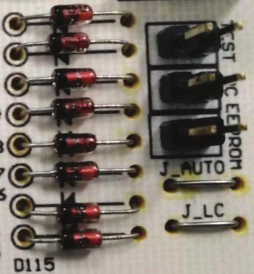
31 Algorithm & Control Default setting Unit: Off Temperature: 24 C Fan speed: High Mode: Cooling Applicable for PCB W_2_03C Only (Refer product line up for model list) Cut off the jumper J_AUTO to disable the Auto Random Restart function Applicable for PCB W_2_03D, W_2_03E & W_2_03E_M (Refer product line up for model list) Cut off the jumper J_AUTO to disable the Auto Random Restart function Applicable for PCB W_2_04A & W_2_04B (For all class 50 & class 60) Cut off the jumper J_AUTO to disable the Auto Random Restart function 23
32 Algorithm & Control 2.14 Four Way Valve Control Change over switching is only carried out during operation. OFF delayed is applied when the coil switches from ON to OFF Operating mode Heat, except for defrost Cool Dry Defrost 4-way valve is ON OFF 2.15 Outdoor Fan Control Determine from Compressor target rotation: higher fan speed with higher rotation. Outdoor air temperature. Cool mode: Higher fan speed with higher outdoor air temperature. Heat mode: Higher fan speed with lower outdoor air temperature. When compressor stops, fan OFF delay of 30 seconds is carried out 2.16 Rotation Regulating Functions Upper limit rotation Command rotation Limit rotation Target rotation Starting rotation T Defrost* * Defrost control for heat pump model only Lower limit rotation Starting Rotation Starting Control To avoid excessive oil discharge from compressor or to promote oil lubrication during startup. To prevent liquid flood back to the compressor. To limit starting current. When compressor starts to rotate from OFF to ON, compressor rotation is set to run gradually to each upper limit at a specific timer setting. Compressor rotation, f d c b a 1 2 Time (min) 24
33 Algorithm & Control Model RXN25/35L ARXN25/35L RXN50/60L ARXN50/60L RXB50/60A RXB50/60B RXN50/60M RXC50/60A RXN25/35MV1 RXN25/35MV1B RXN25/35MV1B9 ARXN25/35MV1B RXN25/35N ARXN25/35MV1B7 ARXN25/35MV16 ARXN25/35N RXK25/35AV1B RXC25/35A a Hz (Time, s) b Hz (Time, s) c Hz (Time, s) d Hz (Time, s) Max Hz (Time, s) 38 (60) 52 (120) 66 (120) 80 (120) 94 (120) 35 (60) 55 (120) 75 (360) (120) 70 (200) 85 (470) (180) 54 (420) 72 (180) 90 (120) - 40 (180) 54 (420) 72 (180) 90 (120) Command Rotation Cut in upon termination of Starting Control. Achieve capacity control by controlling the compressor rotation based on: Temperature difference between set and room temperature, T. Limit Rotation. Defrost control Fuzzy Control (Applicable for ARXN/RXN50/60L) Based on temperature difference, T, current fan speed setting & current indoor operating mode at every 30 seconds interval. Temperature Difference Condition 1 T Condition 2 d T T t = T room - T set d T t = T t - T t-1 Use to set target for compressor frequency change Compressor frequency is increased or decreased 25
34 Algorithm & Control PI Control P control: T of each indoor is calculated at every sampling time of 20s and compressor rotation is adjusted according to the difference from the previously calculated rotation. I control: if the operating frequency is not changed more than a certain fixed time: If Σ T is small : lower frequency. If Σ T is large : increase frequency Limit Rotation Determine from Upper limit rotation A minimum value was determined among the upper limits rotation, i.e. protection controls. Lower limit rotation A maximum value was determined among the lower limits rotation, i.e. protection controls. Generally, compressor rotation is controlled within 5 zones: stop, drop, keep, up and reset subjected to a particular operating temperature/current/pressure. Zone Stop Drop Keep Up Reset Control Compressor is stopped when a certain limit reaches the stop zone for abnormality correction. Frequency will be dropped with a timer setting. Frequency is maintained at lower/upper limit. Frequency will be increased with a timer setting. Frequency lower/upper limit is canceled and returned to command rotation Defrost Cycle During defrost Compressor 4-way valve EXV in operation room Outdoor fan Indoor fan All models ON OFF Fixed opening OFF OFF Condition for entering defrost Compressor minimum run time 6 minutes OR Compressor accumulated run time of 45 minutes if Outdoor coil < 3 C. Condition for terminating defrost Outdoor coil > 12 C or Total defrost timer of 650 seconds Indoor Coil Freeze Prevention Only available in cooling mode. When the indoor coil temperature < 2 C, the compressor starts to drop the frequency. This protection will cut in when: Indoor coil temperature < 0 C for more than 180s. Compressor will stop, outdoor fan stop after 30s and indoor fan can only run at lowest fan speed. The unit can only be restarted after 3 minutes. When the indoor coil temperature > 13 C, the compressor frequency will be reset based on the outdoor ambient, room and set temperature. 26
35 Algorithm & Control 2.19 High Pressure Protection To prevent high pressure in the system. Compressor operating frequency is adjusted based on upper limit of coil temperature. Upper Limit Coil Temperature 64 C A B C Compressor frequency The compressor frequency is adjusted based on coil temperature: During cooling mode : outdoor coil temperature. During heating mode : indoor coil temperature. This protection is activated when the coil temperature > 64 C, the compressor stops and outdoor fan stops after 30s.The unit can only be restarted after 3 minutes Discharge Pipe Temperature Control Used as a measure of the compressor s internal temperature. Compressor frequency is control to keep this temperature from going up further when it rises above a certain level. Discharge temperature 110 C Stop zone 102 C Drop zone 99 C Frequency keep zone 90 C Reset zone If compressor discharge temperature > 102 C for the first time, this control starts and sets the current frequency as upper limit. At the same time, running frequency starts to reduce by 1 step and so on, until temperature falls between 99 C and 90 C at the keep zone. This protection is activated when the compressor discharge temperature > 110 C. The compressor will stop and considered trip. If the compressor discharge temperature < 90 C, the compressor frequency will be reset based on the outdoor ambient, set and room temperature. 27
36 Algorithm & Control 2.21 Oil Recovery Control (Applicable for ARXN/RXN50/60L) When the compressor operates for certain duration at low frequency, the oil level in the compressor may become low due to incomplete oil return. To prevent damage to the compressor or compressor lock due to low oil level. To promote refrigerant flow to carry the oil back to the compressor. Entering condition: Compressor rotation < 35 Hz, at the end of a 20 minutes timer: set lower limit rotation to 35 Hz & EXV opening is fixed at current opening + 50 pulse. This control is reset when rotation > 35 Hz. (2.22 Overall Current Control) 2.22 Overall Current Control To monitor the overall current and to restrict the compressor upper limit rotation in order to prevent circuit breakers from exceeding the rated capacity. Detected during compressor running. Model L1 RXN25/35L ARXN25/35L 14.0A Current (A) L1 L2 L3 Stop zone Frequency reduce zone Frequency remain zone Reset zone RXN25M/N ARXN25M/N RXK25A RXC25A RXN35M/N ARXN35M/N RXK35A RXC35A ARXN50/60L RXB50/60A RXN50/60L/M/N ARXN50/60M/N RXK50/60A RXB50/60B/C ARXB50/60C RXC50/60A 9.5A 10.0A 12.0A 16.0A When the input current for running compressor exceeds L2, the running frequency will be reduced by 1 step. If the current still exceeds L2, frequency will be reduced by another step until total current falls between L2 and L3. This protection cuts in when the input current exceeds L1 for 2 seconds. Compressor will stop and it is considered total current overload. If input current < L3, the compressor frequency is reset based on the outdoor ambient, set and room temperature. 28

37 Service Diagnosis 3.0 Service Diagnosis 3.1 Error Indication from Indoor Indoor model FTXN25/35/50/60L/M, FTXB50/60/A/B/C ATXN25/35/50/60L/M, ATXB50/60C LED display will either be ON during operation or blinking (green color) when any error occur as in below table. The blinking pattern does not indicate error details The error details needs to be retrieved from remote controller in error code form. LED blinks here SLEEP (RED) COOL/HEAT (GREEN/RED) Green Red Red Green TIMER (ORANGE) Operation / Fault Indication Cooling mode Heating mode Auto mode in heating operation Auto mode in cooling operation Time Off (when unit is on) Time On (when unit is off) Sleep mode on Green Green Red Green Fan mode on Dry mode on Defrost operation Error indication ON Blinking 29
 when any error occur as in below table.")
38 Service Diagnosis Indoor model FTXN25/35/50/60N, FTXC25/35/50/60A, ATXN25/35/50/60N LED display will either be ON during operation or blinking (blue color) when any error occur as in below table. The blinking pattern does not indicate error details The error details needs to be retrieved from remote controller in error code form. LED blinks here SLEEP (ORANGE) COOL/HEAT (BLUE/RED) Blue Red Red Blue TIMER (WHITE) Operation / Fault Indication Cooling mode Heating mode Auto mode in heating operation Auto mode in cooling operation Timer On Sleep mode on Blue Blue Red Blue Fan mode on Dry mode on Defrost operation Unit error ON Blinking 30


39 Service Diagnosis Indoor model FTXK25/35/50/60A LED display will either change color under different running condition or blinking (blue color) when any error occur as in below table. The blinking pattern does not indicate error details. The error details needs to be retrieved from remote controller in error code form. COOL/HEAT/TIMER (BLUE/RED/VIOLET) Blue Red Red Blue Violet Blue Blue Red Blue Operation / Fault Indication Cooling mode Heating mode Auto mode in heating operation Auto mode in cooling operation Time On Fan mode on Dry mode on Defrost operation Error indication ON Blinking 31


40 Service Diagnosis 3.2 Error Code retrieved by remote controller Remote controller model BRC52A61 & BRC52B63 Mode button ON/OFF button ON TIMER CANCEL button OFF TIMER CANCEL button ON TIMER CANCEL button OFF TIMER CANCEL button BRC52A61 BRC52B63 Operating Guide 1. Hold down ON TIMER CANCEL or OFF TIMER CANCEL for 5 seconds until indication flashes on the remote controller temperature display section. 2. Then, press the same button repeatedly. A series of error code will appear until indoor buzzer produces a long beep. The corresponding error code is indicated on the remote controller temperature display section. 3. Indoor unit buzzer will produce a long beep if the remote controller error code matched with unit error. 4. A short and two consecutive beeps is not the unit error. For two consecutives beeps, it indicates either the alphabet or number is correct. 5. The code display will cancel itself if the button is not pressed for 1 minute 32

41 Service Diagnosis Last State Error retrieved by remote controller BRC52A61 & BRC52B63 Operating Guide 1. Remove battery from remote controller. 2. Replace battery again into remote controller. 3. Press Mode & ON/OFF buttons together. 4. The will show at temperature section. 5. Press Mode button to 5: Press Power On toward the indoor unit. Unit LED blinks two times indicate received signal. 7. ON hold fan button till screen become normal display. 8. Repeat the normal step to retrieve error. (by using remote controller step. Holding TIMER CANCEL ) 9. By using this method, the error shown will be Last State Error. (Previous error in the unit) Wired controller BRC51A61 The error will show at the LCD display. Last State Error retrieved by wired controller BRC51A61 Press SLEEP & TIMER ACTIVE simultaneously for 5 seconds and the error will flash. Remark : Wired controller is an optional accessory 33


42 Service Diagnosis 3.3 Error Indication from Outdoor ARXN/RXN50/60L, RXB50/60A - 7 Segment Display It is located inside outdoor unit control panel beside the terminal block. Control panel cover has to be removed to get access to the 7 segment display. When there is no error, the compressor running frequency is displayed. When there is an error, the error code flashes as below: rmal operation Flashing Error Code In addition, 7 segment also can be used to retrieve unit operating conditions such as running current, DC voltage, ambient temperature, indoor air temperature, etc. By pressing the tact switch, the 7 segment will start to flash from. Press again, it will show and subsequent running number show the parameter number. Then, the 7 segment will flash again showing the parameter measurement. When the 7 segment display is left untouched for 5 min, the display will light off (Dim). 34
43 Service Diagnosis Parameter Number Parameter Description Unit/Range 00 Compressor Actual Rotation r/s 01 Compressor Target Rotation r/s 02 DC Bus Voltage VDC 03 Total Current (x10) A 04 Outdoor Air Temperature C 05 Outdoor Heat Exchanger Temperature C 06 Compressor Discharge Temperature C 07 Outdoor Heatsink Temperature C 08 Indoor Air Temperature C 09 Indoor Heat Exchanger Temperature C 10 Electronic Expansion Valve Opening Pulse 41 Target Discharge Temperature C 35
44 Service Diagnosis 3.4 Error code description for Inverter. ERROR CODE ERROR DESCRIPTION ARXN/ RXN50/60L RX50/60A ARXN/RXN25/35L ARXN/RXN25/35M/N ARXN/RXN50/60M/N RXB50/60B RXK25/35/50/60A 1 00 NORMAL O O 2 A1 INDOOR PCB ABNORMALITY O O 3 A5 ANTIFREEZE PROTECTION OR HIGH PRESSURE CONTROL 4 A6 INDOOR FAN MOTOR ABNORMALITY O O 5 C4 6 C9 INDOOR HEAT EXCHANGER THERMISTOR ABNORMALITY INDOOR ROOM THERMISTOR ABNORMALITY 7 E1 OUTDOOR PCB ABNORMALITY - O 8 E5 COMPRESSOR OVERLOAD O O 9 E6 COMPRESSOR LOCK/START-UP ABNORMALITY 10 E7 OUTDOOR FAN MOTOR LOCK O O 11 E8 AC INPUT OVER CURRENT O O 12 EA 4 WAY VALVE ABNORMALITY O O 13 F3 DISCHARGE PIPE OVERHEAT O O 14 F6 HEAT EXCHANGER OVERHEAT O O 15 H0 16 H6 COMPRESSOR SENSOR SYSTEM ABNORMAL POSITION SENSOR ABNORMAL (COMPRESSOR) O O O O O O O O - O 17 H8 AC CURRENT SENSOR ABNORMALITY O O 18 H9 19 J3 20 J6 21 L3 22 L4 OUTDOOR AIR THERMISTOR ABNORMALITY COMPRESSOR DISCHARGE PIPE THERMISTOR ABNORMALITY OUTDOOR HEAT EXCHANGER THERMISTOR ABNORMALITY ELECTRICAL BOX TEMPERATURE RISE (COMPRESSOR OFF) HEAT SINK OVERHEAT (COMPRESSOR ON) 23 L5 IPM ABNORMALITY O O 24 P4 HEAT SINK THERMISTOR ABNORMALITY 25 U0 INSUFFICIENT GAS O O 26 U2 DC VOLTAGE OUT OF RANGE O O 27 U4 COMMUNICATION ABNORMALITY O O 28 UA INSTALLATION ABNORMALITY O O O O O O O O O O O O O O O O Remark: O : Function - : t Applicable 36
45 Service Diagnosis Description Possible Root cause Troubleshooting INDOOR PCB ABNORMALITY A1 1. Faulty indoor PCB. 2. Faulty connector connection at indoor. Turn off unit. Check indoor PCB connector conditions (including PCB to terminal block and all PCB wire connector). Any sign of loose or abnormal. Connect correctly and operate again. Replace indoor PCB and operate again. 37
46 Service Diagnosis Description Possible Root cause Troubleshooting ANTIFREEZE PROTECTION OR HIGH PRESSURE CONTROL 1. Indoor air filter, heat exchanger block due to dust accumulation. 2. Indoor air short circuit. 3. Indoor coil thermistor faulty. 4. Indoor PCB faulty. 5. Fan blower dirty. A5 Check indoor air flow. Any air short circuit? Check intake air filter. Provide sufficient air passage. Is it very dirty? Clean the air filter. Check the dust accumulate indoor coil. Is it very dirty? Clean the indoor coil. Check fan blower condition. Is it very dirty? Clean fan blower. Check indoor coil thermistor resistance. # Refer to thermistor resistance table.(page 72, 6.1) Does it conform to the thermistor resistance table? Change indoor PCB. Change indoor thermistor. 38
47 Service Diagnosis Description Possible Root cause Troubleshooting A6 INDOOR FAN MOTOR ABNORMALITY 1. Indoor fan motor winding short, or the motor lead wire broken. 2. Indoor PCB faulty. Turn off power supply and rotate fan by hand. Does it rotate? Change fan motor. Check fan motor connector condition. Does it connect properly? Connect correctly. Change PCB and turn on power. Change fan motor. Description Possible Root cause Troubleshooting INDOOR HEAT EXCHANGER THERMISTOR ABNORMALITY 1. Thermistor, connector faulty. 2. Indoor PCB faulty. Check the thermistor connector condition. C4 rmal? Correct the connection Check thermistor resistance value. # Refer thermistor resistance table.(page 72, item 6.1) rmal? Replace thermistor Replace PCB. *Remark: Refer Thermistor resistance check procedure in Appendix A.(Page 72, item 6.1) 39
48 Service Diagnosis Description Possible Root cause Troubleshooting C9 INDOOR ROOM THERMISTOR ABNORMALITY 1. Thermistor, connector faulty. 2. Indoor PCB faulty. Check the thermistor connector condition. rmal? Correct the connection Check thermistor resistance value. # Refer thermistor resistance table.(page 72, item 6.1) rmal? Replace thermistor Replace PCB. 40
49 Service Diagnosis Description Possible Root cause Troubleshooting OUTDOOR PCB ABNORMALITY E1 1. Micro Controller program run-away due to external factor such as ise, Momentary voltage drop, Momentary power failure. 2. Damage of EEPROM. 3. Faulty outdoor unit PCB. 4. Broken hardness between PCB. Turn on the power again. Error still occur? Replace outdoor PCB. Check if the outdoor unit is grounded. Grounded? Ground the system. Is the harness broken? Replace outdoor PCB. Replace the harness. 41
50 Service Diagnosis Description Possible Root cause Troubleshooting E5 (All models except ARXN/RXN50/60L, RXB50/60A) COMPRESSOR OVERLOAD 1. Refrigerant Shortage way valve malfunction. 3. Stop valve malfunction. 4. Outdoor unit PCB defective. 5. Water mixed in refrigerant. 6. Electronic expansion valve defective. 7. Disconnection of discharge pipe thermistor. 8. Faulty discharge pipe thermistor. 9. Disconnection of connector S Electronic expansion valve or coil malfunction. 11. Disconnection of 2 terminals of OL. Discharge pipe thermistor disconnected? Insert thermistor in position. Thermistor resistance normal? Replace thermistor. Connectors properly connected? # Refer to thermistor resistance table.(page 72, item 6.1) Connect back the connectors. Disconnect connector S40 from PCB. Check resistance of 2 terminals connector S40. Disconnect 2 terminals of OL. Check electronic expansion. Malfunction? Check four way valve. Malfunction? Check refrigerant line. Resistance between 2 Replace electronic expansion or the coil. Replace four way valve or the coil. Replace outdoor PCB. Disconnect 2 terminals of OL. Disconnect 2 terminals of OL. Malfunction? Refer refrigerant line check procedures. Replace outdoor PCB. *Remark: Please refer to Appendix A for Electronic expansion valve (page 74,item 6.2), four way valve (page 74,item 6.3) and refrigerant line checking procedures (page 75,item 6.4). 42
51 Service Diagnosis Description Possible Root cause Troubleshooting COMPRESSOR OVERLOAD E5 (ARXN/RXN50/60L, RXB50/60A) 1. Refrigerant Shortage way valve malfunction. 3. Electronic expansion valve defective. 4. Outdoor unit PCB defective. 5. Water mixed in refrigerant. Turn off unit. Disconnect compressor wire hardness (U.V.W) and check winding. Resistance #Compressor winding resistance 1.18 Change compressor. on unit. Compressor stop without Change outdoor PCB. Check expansion. #Refer page 74 item 6.2 Check four #Refer page 74 item 6.3 Check #Refer page 75 item 6.4 check procedures. 43
52 Service Diagnosis Description Possible Root cause Troubleshooting E6 COMPRESSOR LOCK/START-UP ABNORMALITY 1. Compressor locked. 2. Compressor harness disconnect. Turn off power. Disconnect harnesses U, V and W. Check with Inverter analyzer. rmal? Correct power supply or replace outdoor unit PCB. Turn off power and reconnect harnesses. Turn on power again and restart system. Emergency stop without compressor running? Replace the compressor. System shut down after errors repeated several times? Check outdoor electronic expansion valve coil. Replace it as required. Replace the compressor. 44
53 Service Diagnosis Description Possible Root cause Troubleshooting OUTDOOR FAN MOTOR LOCK E7 1. Fan motor breakdown. 2. Harness or connector disconnected between fan motor and PCB or in poor contact. 3. Foreign matter stuck in fan. 4. Defective outdoor unit PCB. Fan motor connector disconnected? Turn off power and reconnect connector. Foreign matters in or arround fan? Remove foreign matters. Turn on the power. Rotate the fan. Fan rotates smoothly? Replace outdoor fan motor. Check rotation pulse input on outdoor unit PCB. Pulse signal generated? Replace outdoor fan motor. Replace outdoor PCB. *Remark: Refer Appendix A for rotation pulse check.(page 76, item 6.5) 45
54 Service Diagnosis Description Possible Root cause Troubleshooting AC INPUT OVER CURRENT E8 1. Over current due to compressor failure. 2. Over current due to defective outdoor unit PCB. 3. Over current due to defective power transistor. 4. Over current due to short-circuit. Measure the input current. Input current flowing above its stop level? Replace the outdoor unit Check outdoor fan motor, outdoor ambient temperature, refrigerant charge level Any abnormal? Refer to the type of abnormality and conduct proper service. Turn off the power and disconnect the harness U, V and W. Check with the inverter checker. Compressor faulty? Change Compressor. Change outdoor Control Box. 46
55 Service Diagnosis Description Possible Root cause Troubleshooting 4 WAY VALVE ABNORMALITY EA 1. Thermistor defective way valve defective. 3. Outdoor PCB defective. 4. Insufficient gas. 5. Foreign substance mixed in refrigerant. 6. Stop valve defective. 7. Disconnect of 4 way valve coil. Four way valve coil disconnected (loose)? Correct the four way valve coil. Harness disconnected? Reconnect the harness. Check the continuity of the four way valve coil and harness. Disconnect the harness from the connector. Resistance between harnesses. within spec? Replace the four way valve coil. Check the four way valve switching output. Malfunction Replace the outdoor unit PCB. Functioning Any thermistor disconnected? Reconnect the thermistor(s). Check the thermistors. Malfunction Replace the defective thermistor(s). Functioning Check the refrigerant line. Functioning Malfunction Refer to the refrigerant line check procedure. Replace the four way valve (defective or dust-clogged). *Remark: Refer to Appendix A for thermistor resistance checking procedures.(page 72, item 6.1) Refer to Appendix A for Four way valve performance checking procedures.(page 74,item 6.2) Refer to Appendix A for Inverter unit refrigerant check procedures.(page 75,item 6.4) 47
56 Service Diagnosis Description Possible Root cause Troubleshooting DISCHARGE PIPE OVERHEAT F3 1. Refrigerant shortage. 2. Four way valve malfunctioning. 3. Discharge pipe thermistor defective. 4. Outdoor PCB defective. 5. Water mixed in the local piping. 6. EXV defective. 7. Stop Valve defective. Check the thermistors. Functioning Malfunction * Discharge pipe thermistor * Outdoor heat exchanger thermistor * Outdoor temperature thermistor Replace the defective thermistor(s). Check the electronic expansion valve. Malfunction Replace the electronic expansion valve or the coil. Functioning Check the refrigerant line. Functioning Malfunction * Refrigerant shortage * Four way valve * Water mixed * Stop valve Refer to the refrigerant line check procedure. Replace the outdoor unit PCB. *Remark: Refer to Appendix A for thermistor resistance checking procedures.(page 72, item 6.1) Refer to Appendix A for Electronic Expansion Valve (EXV) checking procedures. (Page 74, item 6.2) Refer to Appendix A for Inverter unit refrigerant check procedures. (Page 75, item 6.4) 48
57 Service Diagnosis Description Possible Root cause Troubleshooting HEAT EXCHANGER OVERHEAT F6 1. The installation space is not large enough. 2. Faulty outdoor fan motor. 3. Faulty EXV. 4. Faulty outdoor heat exchanger thermistor. 5. Faulty stop valve. 6. Dirty heat exchanger. 7. Unit overcharge. 8. Defective outdoor unit PCB. Check the installation space. Check the installation condition. Check the outdoor fan. Functioning Functioning Malfunction Malfunction Change the installation location or direction. Clean the outdoor heat exchanger. Replace the outdoor fan motor. Reconnect the connector or fan motor lead wires. Check the electronic expansion valve. Malfunction Replace the electronic expansion valve or the coil. Replace the outdoor unit PCB. Functioning Check the outdoor heat exchanger thermistor. Malfunction Replace the outdoor heat exchanger thermistor. Functioning Replace the outdoor unit PCB. *Remark: Refer to Appendix A for thermistor resistance checking procedures.(page 72, item 6.1) Refer to Appendix A for Electronic Expansion Valve (EXV) checking procedures. (Page 74, item 6.2) Refer to Appendix A for Inverter unit refrigerant check procedures. (Page 75, item 6.4) Refer to Appendix A for Installation condition check. (Page 77, item 6.6) 49
58 Service Diagnosis Description Possible Root cause Troubleshooting H0 (ARXN/RXN/RXB50/60A) COMPRESSOR SENSOR SYSTEM ABNORMAL 1. Broken and disconnected harness. 2. Outdoor unit PCB defective. 3. Defective compressor. Check reactor connection. Any abnormal? Connect back reactor. Check reactor resistance. # Disconnect the reactor wire and measure resistance between terminal. Change reactor. Check compressor resistance. Change Compressor. Change outdoor PCB. 50
59 Service Diagnosis Description Possible Root cause Troubleshooting H0 (ARXN/RXN25/35M/N, RXK25/35A) COMPRESSOR SENSOR SYSTEM ABNORMAL 1. Broken and disconnected harness. 2. Outdoor unit PCB defective. Check the harness S30. Is the harness broken? Replace the harness. Turn off the power and turn it on again. Get restarted and error displayed again? problem. Keep on running. Replace the PCB. 51
60 Service Diagnosis Description Possible Root cause Troubleshooting H6 (ARXN/RXN50/60L, RXB50/60A) POSITION SENSOR ABNORMAL (COMPRESSOR) 1. Compressor relay cable disconnected. 2. Compressor itself defective. 3. Outdoor PCB defective. 4. Stop valve closed. 5. Input voltage out of specification. Check for short circuit. rmal? Replace the outdoor unit PCB, outdoor unit fan. Check the electrolytic capacitor voltage. Compressor harness connected as specified? Reconnect as specified. Turn off the power. Disconnect the harness U, V and W. Check with inverter checker. Any LED off? Correct power supply or replace outdoor PCB. Replace compressor. 52
61 Service Diagnosis Description Possible Root cause Troubleshooting H6 (RXN25/35M/N, RXK25/35A) POSITION SENSOR ABNORMAL (COMPRESSOR) 1. Compressor relay cable disconnected. 2. Compressor itself defective. 3. Outdoor PCB defective. 4. Stop valve closed. 5. Input voltage out of specification. Check for short circuit. rmal? Replace the outdoor unit PCB, outdoor unit fan. Check the electrolytic capacitor voltage. DC320 ± 30 V? Replace the outdoor unit PCB. Electricals or compressor harnesses connected as specified? Reconnect as specified. Turn off the power. Disconnect the harness U, V and W. Check with inverter checker (*). * Inverter checker Part.: Any LED off? Correct the power supply or replace the outdoor unit PCB. Replace the compressor. 53
62 Service Diagnosis Description Possible Root cause Troubleshooting H6 (ARXN/RXN50/60M/N, RXK50/60A) POSITION SENSOR ABNORMAL (COMPRESSOR) 1. Compressor relay cable disconnected. 2. Compressor itself defective. 3. Outdoor PCB defective. 4. Stop valve closed. 5. Input voltage out of specification Turn off the power. Check the power supply voltage. Voltage as rated? Check stop valve. Correct the power supply. OK? Check the short circuit of the diode bridge. Replace the stop valve. rmal? Check the connection. Replace the outdoor unit PCB. Electrical components or compressor harnesses connected as specified? Turn on the power. Check the electrolytic capacitor voltage. Reconnect the electrical components or compressor harnesses as specified. 320 = 50 VDC? Turn off the power. Disconnect the harnesses U, V and W. Replace the outdoor unit PCB. Check with the inverter analyzer. * Inverter analyzer: RSUK0917C Any LED off? Replace the compressor. Correct the power supply or replace the outdoor unit PCB. Remark: Refer to Appendix A for Diode bridge short circuit check procedures.(page 78, item 6.8) 54
63 Service Diagnosis Description Possible Root cause Troubleshooting H8 AC CURRENT SENSOR ABNORMALITY 1. Internal wiring broken. 2. Outdoor unit PCB defective. Check compressor harness connection. Connection correct? Reconnect it correctly. Restart the system and check connector between main board and IPM board. Does it connect properly? Reconnect it properly. Change outdoor PCB. *Remark: This error is only applicable for model ARXN/RXN50/60L and RXB50/60A. 55
64 Service Diagnosis Description Possible Root cause Troubleshooting Thermistor or related abnormality H9, J3, J6, P4 H9: OUTDOOR AIR THERMISTOR ABNORMALITY J3: COMPRESSOR DISCHARGE PIPE THERMISTOR ABNORMALITY J6: OUTDOOR HEAT EXCHANGER THERMISTOR ABNORMALITY P4: HEAT SINK THERMISTOR ABNORMALITY 1. Disconnection of the connector for the thermistor. 2. Thermistor corresponding to the error code is defective. 3. Defective heat exchanger thermistor in the case of J3 error (outdoor heat exchanger thermistor in cooling operation, or indoor heat exchanger thermistor in heating operation). 4. Defective outdoor unit PCB. Turn on the power again. Error displayed again on remote controller? Reconnect the connectors or thermistors. Check the thermistor resistance value. J3 error: the discharge pipe temperature is lower than the heat exchanger temperature. Cooling: Outdoor heat exchanger temperature. Heating: Indoor heat exchanger temperature. rmal? Replace the defective thermistor(s) of the following thermistors. * Outdoor temperature thermistor. * Discharge pipe thermistor. * Outdoor heat exchanger thermistor. Check the indoor heat exchanger thermistor resistance value in the heating operation. Indoor heat exchanger thermistor functioning? Replace the indoor heat exchanger thermistor. Replace the outdoor unit PCB. *Remark: Refer to Appendix A for thernistor resistance check procedures.(page 72, item 6.1) 56
65 Service Diagnosis Description Possible Root cause Troubleshooting L3 ELECTRICAL BOX TEMPERATURE RISE (COMPRESSOR OFF) 1. Fin temperature rise due to defective outdoor unit fan. 2. Fin temperature rise due to short circuit. 3. Fin thermistor defective. 4. Connector in poor contact. 5. Outdoor unit PCB defective. Turn off the unit and turn on back after 20 mins. Error again? Check outdoor fan. Check heat sink thermistor resistance. Outdoor fan functioning? Change outdoor fan motor. Change thermistor. Resistance normal? Heat sink dirty? Check installation condition. Change outdoor PCB. Heat sink temperature > A C? Clean the heat sink. Change heat sink or check outdoor fan condition. Models A C RXB50/60B 80 ARXN/RXN25/35M 78 ARXN/RXN50/60M 122 *Remark: Refer to Appendix A for thermistor resistance check procedures.(page 72, item 6.1) Refer to Appendix A for outdoor fan system check. (Page 77, item 6.7) Refer to Appendix A for installation condition check. (Page 77, item 6.6) 57
66 Service Diagnosis Description Possible Root cause Troubleshooting Heat sink overheat L4 1. Fin temperature rise due to short circuit. 2. Fin temperature rise due to defective outdoor unit fan. 3. Fin thermistor defective. 4. Connector in poor contact. 5. Outdoor unit PCB defective. 6. Silicon grease is not applied properly on the radiation fin after replacing outdoor unit PCB. Turn off the power and turn it on again to start the system. Error displayed again? Has the PCB been replaced? Check if silicon grease is applied properly on the radiation fin. If not, apply the silicon grease. Check the radiation fin temperature. Above A C? Replace the outdoor unit PCB. Check the outdoor fan. Functioning Malfunction Replace the outdoor fan motor. Correct the connectors and fan motor leads. Replace the outdoor unit PCB. Radiation fin dirty? Check the installation condition. Clean up the radiation fin. Models A C ARXN/RXN50/60L 85 ARXN/RXN25/35M 93 ARXN/RXN50/60M,RXB50/60B 85 *Remark: Refer to Appendix A for outdoor fan system check.(page 77, item 6.7) Refer to Appendix A for installation condition check. (Page 77, item 6.6) 58
67 Service Diagnosis Description Possible Root cause Troubleshooting IPM ABNORMALITY L5 1. Over current due to defective power transistor. 2. Over current due to wrong internal wiring. 3. Over current due to abnormal supply voltage. 4. Over current due to defective PCB. 5. Error detection due to defective PCB. 6. Over- current due to closed stop valve. 7. Over current due to compressor failure. 8. Over current due to poor installation condition. 9. Connection between main board and IPM board is not properly connect. Check the installation condition. Stop valve fully open? Fully open the stop valve. Turn off the power and turn it on again to start the system. See if the same error occurs. Error again? Turn off power and disconnect the harnesses U, V and W. Monitor the power supply voltage and suction pressures, and other factors for a long term. Check with the inverter analyzer. Any LED off? Correct the power supply or replace the outdoor unit PCB. Turn off the power and reconnect the harnesses. Turn on the power again and start operation. Check the power supply voltage. Voltage as rated? Correct the power supply. Replace the compressor. *Remark: Refer to Appendix A for installation condition check. (Page 77, item 6.6) 59
68 Service Diagnosis Description Possible Root cause Troubleshooting INSUFFICIENT GAS U0 1. Disconnection of the discharge pipe thermistor, indoor or outdoor heat exchanger,room or outdoor temperature thermistor. 2. Closed stop valve. 3. Refrigerant shortage (refrigerant leakage). 4. Poor compression performance of compressor. 5. Defective electronic expansion valve. Check stop valve. Stop valve closed? Fully open stop valve. Check indoor and outdoor coil thermistor. Thermistor in actual position? Put the thermistor back to actual position. Check the indoor coil, outdoor coil and discharge pipe thermistor resistance. Resistance normal? Change thermistor. Check EXV. EXV functioning? Change EXV. Check refrigerant charge level. Refrigerant charge sufficient? Check for leakage. Change outdoor PCB. Any leakage? Repair the leak point. Add in refrigerant charge. *Remark: Refer to Appendix A for thermistor resistance checking procedures.(page 72, item 6.1) Refer to Appendix A for electronic expansion device checking procedures.(page 74, item 6.2) 60
69 Service Diagnosis Description Possible Root cause Troubleshooting DC VOLTAGE OUT OF RANGE U2 1. Power supply voltage is not as specified. 2. Defective DC voltage detection circuit. 3. Defective over-voltage detection circuit. 4. Defective PAM control part. 5. Disconnection of compressor harness 6. Short circuit inside the fan motor winding. 7. ise. 8. Momentary drop of voltage. 9. Momentary power failure. 10. Defective outdoor unit PCB. Check the power supply voltage. Is the voltage fluctuation within ±10% from the rated value? Correct the power supply. Check the connection of the compressor harness. Loose or disconnected? Reconnect the harness. Does the outdoor fan rotate smoothly? Replace the outdoor fan motor and the outdoor unit PCB. Turn on the power. (Precaution before turning on the power again.) Make sure the power has been off for at least 30 seconds. System restarted? (Repeat a few times.) Replace the outdoor unit PCB. Disturbance factors * ise * Power supply distortion Check for such factors for a long term. 61
70 Service Diagnosis Description Possible Root cause Troubleshooting U4 COMMUNICATION ABNORMALITY 1. Faulty outdoor unit PCB. 2. Faulty indoor unit PCB. 3. Indoor unit outdoor unit signal transmission error due to wiring error. 4. Indoor unit outdoor unit signal transmission error due to disturbed power supply waveform. 5. Indoor unit Outdoor unit signal transmission error due to breaking of wire in the connection wires between the indoor and outdoor units Check the power supply voltage. Is the voltage fluctuation within ±10% from the rated value? Correct the power supply. Check the indoor unit - outdoor unit connection wires. Is there any wiring error? Correct the indoor unit - outdoor unit connection wires. #Refer section 4.0 Wiring Connection Diagram Check the voltage of the connection wires on the indoor terminal board between. 1(L) and SIG, and between. 2 (N)and SIG. Properly connected? Check the LED A on the outdoor unit PCB. Replace the connection wires between the indoor unit and outdoor unit. Is LED A blinking? Rotate the outdoor fan by hand. Does the outdoor fan rotate smoothly? Check the power supply waveform. Diagnose the outdoor unit PCB. Replace the outdoor fan motor and the outdoor unit PCB. Is there any disturbance? Replace the indoor unit PCB. Locate the cause of the disturbance of the power supply waveform, and correct it. *Remark: Refer to Appendix A for power supply waveform check procedures.(page 79, item 6.9) 62
71 Service Diagnosis Description Possible Root cause Troubleshooting INSTALLATION ABNORMALITY UA 1. Wrong models interconnected. 2. Wrong indoor unit PCB mounted. 3. Indoor unit PCB defective. 4. Wrong outdoor unit PCB mounted or defective. Check the combination of the indoor and outdoor unit. OK? Match the compatible models. Are the connecting wires connected properly? Correct the connection. Check the indoor and outdoor PCB part number. Matched compatibly? Change for the correct PCB. Replace the indoor unit PCB (or the outdoor unit PCB). 63
72 Wiring Connection 4.0 Wiring Connection Model: FTXN25/35L-RXN25/35L / ATXN25/35L-ARXN25/35L / FTXN25/35MV1-RXN25/35MV1 / FTXN25/35MV1B-RXN25/35MV1B / FTXN25/35MV1B9-RXN25/35MV1B9 / ATXN25/35MV1B-ARXN25/35MV1B L N POWER SUPPLY V/1Ph/50Hz E 64
73 Wiring Connection Model: ATXN25/35MV16-ARXN25/35MV16 / ATXN25/35MV1B7-ARXN25/35MV1B7 / ATXN20MV16-ARXN20MV16 NOTATION FM: FAN MOTOR AS: AIR SWING MOTOR TH1: ROOM SENSOR L N E POWER SUPPLY V/1Ph/50Hz L N 1 2 SIG 65
74 Wiring Connection Model: FTXN25/35N-RXN25/35N / ATXN25/35N-ARXN25/35N / FTXK25/35A-RXK25/35A / FTXC25/35A-RXC25/35A SIG 2 1 L N 1 2 SIG L N E POWER SUPPLY V/1Ph/50Hz 66
75 Wiring Connection Model: FTXN50/60L-RXN50/60L / ATXN50/60L-ARXN50/60L / FTXB50/60A-RXB50/60A L N E POWER SUPPLY V/1Ph/50Hz 67
76 Wiring Connection Model: FTXN50/60M-RXN50/60M / FTXB50/60B-RXB50/60B / ATXN50/60M-ARXN50/60M L N E POWER SUPPLY V/1Ph/50Hz 68
77 Wiring Connection Model: FTXN50/60N-RXN50/60N / ATXN50/60N-ARXN50/60N / FTXB50/60C-RXB50/60C / FTK50/60A-RXK50/60A / ATXB50/60C-ARXB50/60C / FTXC50/60A-RXC50/60A (OPTIONAL) SIG 2 1 NOTATION: FM: FAN MOTOR AS: AIR SWING MOTOR TH1: ROOM SENSOR Z1C,Z2C: FERRITE CORE FIELD WIRING L N 1 2 SIG L N E POWER SUPPLY V/1Ph/50Hz 69
78 Refrigerant Diagram 5.0 Refrigerant Diagram Model: ATXN/FTXN_L / ARXN/RXN_L / FTXB_A / RXB_A / ATXN/FTXN25/35M/N / ARXN/RXN25/35M/N / FTXK25/35A / RXK25/35A / FTXC25/35A / RXC25/35A Model: FTXC50A/RXC50A MUFFLER 3 WAY VALVE 70
79 Refrigerant Diagram Model: FTXB_B / RXB_B / ATXN/FTXN50/60/M/N / ARXN/RXN50/60/M/N / FTXK50/60A / RXK50/60A / ATXB/FTXB_C / ARXB/RXB_C 71
80 Refrigerant Diagram 6.0 Appendix A: 6.1 Thermistor resistance checking procedures Remove the connectors of thermistors at PCB and measure resistance of each thermistor using tester as shown below. Tester Resistance range Resistance value refer to Resistance table below. RXN/ARXN50/60L RXB50/60A RXN/ARXN25/35L RXN/ARXN25/35/50/60M RXN/ARXN25/35/50/60N RXB50/60B RXB/ARXB50/60C RXC25/35/50/60C Indoor Wall Mounted 10 kω (Table 2) 10 kω (Table 2) Outdoor Outdoor Split 10 kω (Table 2) 20 kω (Table 1) Table 1: Resistance R25 = 20K ohm Temperature ( C) Resistance value (kω)
81 Refrigerant Diagram Table 2: Resistance R25 = 10K ohm t C Rmin (kω) Rnom (kω) Rmax (kω) t C Rmin (kω) Rnom (kω) Rmax (kω) Remarks: At ambient temperature of 25ᵒC, nominal resistance value is 10.00kΩ. 73
82 Refrigerant Diagram 6.2 Electronic Expansion Valve (EXV) checking procedures a. Check if the EXV connector is correctly connected to PCB. b. Turn power off and on again, and check if EXV generates a latching sound. c. If the EXV does not generate a latching sound in above step b., disconnect connector and check continuity using a multimeter. d. Check the continuity between pins [1-6, 3-6, 2-5, 4-5 (between pins 1-6, 2-6, 3-6, 4-6 for harness 5P models)]. If there is no continuity between the pins, EXV coil is faulty. e. If the continuity is confirmed in step d., outdoor PCB is faulty. Harness 6P Harness 5P S20 1 6P Connector Check (R106366) S20 1 (5) 6P Connector Check (R106366) 6.3 Four way valve performance checking procedures Class 25/35 Turn power off and then on again. Start heating operation. *Four way valve coil t Energized Heating: Energized S80 voltage at V with compressor on? *Refer Figure 1 below. Replace outdoor PCB. Disconnect four way valve coil from connector and check the continuity. Four way valve coil resistance at Replace four way valve coil. Replace four way valve. (Fig. 1) Voltage at S80 DC V DC12-15V Compressor ON Time 74
83 Refrigerant Diagram Class 50/60 Turn power off and then on again. Start heating operation. *Four way valve coil t Energized Heating: Energized S80 voltage at VAC with compressor on? *Refer Figure 1 below. Replace outdoor PCB. Disconnect four way valve coil from connector and check the continuity. Four way valve coil resistance at Replace four way valve coil. Replace four way valve. (Fig. 1) Voltage at S VAC Compressor ON Time 6.4 Inverter unit refrigerant check procedures Refrigerant system check. Is the discharge pipe thermistor disconnected from the holder? Reconnect the thermistor. Check for refrigerant leakage. See troubleshooting for U0 error. Replace the refrigerant. 75
84 Refrigerant Diagram 6.5 Rotation pulse check on outdoor unit PCB Turning speed pulse input on outdoor unit PCB check for (A)RXN25/35L, RXN25/35MV1 & RXN25/35MV1B a. Make sure control voltage of DC15V is being applied. b. Make a turn of the fan motor with hand and make sure the pulse (0-15V) appears 4 times at pins 10 and 13. S HV (Hall IC) HU (Hall IC) 15V Free pin Free pin Phase W Free pin Free pin Phase V Free pin Free pin Phase U Rotation pulse check on outdoor unit PCB for RXN25/35MV1B9, ARXN25/35MV1B(7), RXK25/35A, (A)RXN25/35N, RXC25/35A and all class 50/60 except (A)RXN50/60L, RXB50/60A/B Make sure that the voltage of 320 ± 30 V is applied. 1. Set operation off and power off. Disconnect the connector S Check that the voltage between the pins 4 & 7 is 320 VDC. 3. Check that the control voltage between the pins 3 & 4 is 15 VDC. 4. Check that the rotation command voltage between the pins 2 & 4 is VDC. 5. Keep operation off and power off. Connect the connector S Check whether 4 pulses (0 ~ 15 VDC) are output at the pins 1-4 when the fan motor is rotated 1 turn by hand. When the fuse is melted, check the outdoor fan motor for proper function. If NG in step 2 : Defective PCB and replace the outdoor unit PCB. If NG in step 4 : Defective Hall IC and replace the outdoor fan motor. If OK in both steps 2 and 4,replace the outdoor unit PCB. PCB S71 Actual rotation pulse input (0 ~ 15 VDC) Rotation command voltage (0 ~ 6.5 VDC) Control voltage 15 VDC 320 VDC 76
85 Refrigerant Diagram 6.6 Installation condition check Installation condition check. Check the allowable dimensions of the air suction and discharge area. NG Change the installation location,direction or remove obstacles. OK Is the discharged air short-circuited? Change the installation location,direction or remove obstacles. Is the outdoor heat exchanger very dirty? Is the airflow blocked by obstacles or winds blowing in the opposite direction? Clean the outdoor heat exchanger. Check the outdoor temperature. (The outdoor temperature should be within the operation range.) Change the installation location,direction or remove obstacles. 6.7 Outdoor fan system check DC motor Check the outdoor fan system. Outdoor fan running? Fan motor lead wire connector disconnected? Refer to Appendix A Rotation pulse check on outdoor unit PCB. Refer Page 78,item 6.6 Outdoor fan system is functioning. Reconnect the connector. 77

86 Refrigerant Diagram 6.8 Diode bridge short circuit check procedures Power transistor check for class 25 & class 35 Check to make sure that the voltage between the terminal of Power transistor (+) and (-) is approx. 0 volt before checking power transistor. <Measuring method> Disconnect the compressor harness connector from the outdoor unit PCB. To disengage the connector, press the protrusion on the connector. Then, follow the procedure below to measure resistance between power transistor (+) and (-) and the U, V and W terminals of the compressor connector with a multi-tester. Evaluate the measurement results for a pass/fail judgment. <Power transistor check> Negative (-) terminal of tester (positive terminal (+) for digital tester) Positive (+) terminal of tester (negative terminal (-) for digital tester) Power transistor (+) UVW UVW Power transistor (+) Power transistor (-) UVW rmal resistance Several kω to several MΩ (*) Unacceptable resistance Short (0Ω) or open UVW Power transistor (-) Main circuit short check for class 50 & class 60 Check to make sure that the voltage between (+) and (-) of the diode bridge (DB1) is approximately 0 V before checking. Measure the resistance between the pins of the DB1 referring to the table below. If the resistance is or less than 1 kw, short circuit occurs on the main circuit. Negative (-) terminal of multimeter Positive (+) terminal of multimeter Resistance is OK - (2, 3) + (4) - (2, 3) - (1) + (4) - (2, 3) - (1) - (2, 3) Several kω ~ several MΩ Several kω ~ several MΩ Resistance is NG 0Ω or 0 0 0Ω or *Remark: 1. Use opposite sign of terminal for digital multimeter for measurement ~ 2 ~ 1 Multimeter 78
SERVICE MANUAL. Inverter Wall Mounted Single Split. MODELS Cooling Only. Heatpump SM-5WM-Y-NA-B1
 SERVICE MANUAL Inverter Wall Mounted Single Split MODELS Cooling Only FTKB09AXVJU FTKB12AXVJU FTKB18AXVJU FTKB24AXVJU FTKN09AXVJU FTKN12AXVJU FTKN18AXVJU FTKN24AXVJU Heatpump FTXB09AXVJU FTXB12AXVJU FTXB18AXVJU
SiBE04-808_C. Service Manual. Inverter Pair Wall Mounted Type G-Series. [Applied Models] Inverter Pair : Cooling Only Inverter Pair : Heat Pump
![SiBE04-808_C. Service Manual. Inverter Pair Wall Mounted Type G-Series. [Applied Models] Inverter Pair : Cooling Only Inverter Pair : Heat Pump](/thumbs/88/114609417.jpg "SiBE04-808_C. Service Manual. Inverter Pair Wall Mounted Type G-Series. [Applied Models] Inverter Pair : Cooling Only Inverter Pair : Heat Pump") Service Manual Inverter Pair Wall Mounted Type G-Series [Applied Models] Inverter Pair : Cooling Only Inverter Pair : Heat Pump Inverter Pair Wall Mounted Type G-Series Cooling Only Indoor Unit FTXS20G2V1B
Service Manual Inverter Pair Wall Mounted Type G-Series [Applied Models] Inverter Pair : Cooling Only Inverter Pair : Heat Pump Inverter Pair Wall Mounted Type G-Series Cooling Only Indoor Unit FTXS20G2V1B
SiBE041010EA. Service Manual. Inverter Pair Wall Mounted Type J-Series. [Applied Models] Inverter Pair : Heat Pump
![SiBE041010EA. Service Manual. Inverter Pair Wall Mounted Type J-Series. [Applied Models] Inverter Pair : Heat Pump](/thumbs/88/115408421.jpg "SiBE041010EA. Service Manual. Inverter Pair Wall Mounted Type J-Series. [Applied Models] Inverter Pair : Heat Pump") Service Manual Inverter Pair Wall Mounted Type J-Series [Applied Models] Inverter Pair : Heat Pump Inverter Pair Wall Mounted Type J-Series Heat Pump Indoor Unit FTX20JV1B FTX25JV1B FTX35JV1B FTX20J2V1B
Service Manual Inverter Pair Wall Mounted Type J-Series [Applied Models] Inverter Pair : Heat Pump Inverter Pair Wall Mounted Type J-Series Heat Pump Indoor Unit FTX20JV1B FTX25JV1B FTX35JV1B FTX20J2V1B
Part 3 Troubleshooting
 Part Troubleshooting What is in this part? This part contains the following chapters: Chapter See page Troubleshooting 2 Error Codes: Hydro-box 7 Error Codes: Outdoor Units Error Codes: System Malfunctions
SiBE041525F. Service Manual. Inverter Pair Wall Mounted Type FTX/ATX-K Series. [Applicable Models] Inverter Pair: Heat Pump
![SiBE041525F. Service Manual. Inverter Pair Wall Mounted Type FTX/ATX-K Series. [Applicable Models] Inverter Pair: Heat Pump](/thumbs/92/110790777.jpg "SiBE041525F. Service Manual. Inverter Pair Wall Mounted Type FTX/ATX-K Series. [Applicable Models] Inverter Pair: Heat Pump") Service Manual Inverter Pair Wall Mounted Type FTX/ATX-K Series [Applicable Models] Inverter Pair: Heat Pump Inverter Pair Wall Mounted Type FTX/ATX-K Series Heat Pump Indoor Unit FTX20K(2)V1B FTX50K(M/2)V1B
Service Manual Inverter Pair Wall Mounted Type FTX/ATX-K Series [Applicable Models] Inverter Pair: Heat Pump Inverter Pair Wall Mounted Type FTX/ATX-K Series Heat Pump Indoor Unit FTX20K(2)V1B FTX50K(M/2)V1B
Service Manual. Inverter Pair Floor / Ceiling Suspended Dual Type BA-Series. SiBE05-722_C
 Service Manual Inverter Pair Floor / Ceiling Suspended Dual Type BA-Series [Applied Models] Inverter Pair : Cooling Only Inverter Pair : Heat Pump Inverter Pair Floor / Ceiling Suspended Dual Type BA-Series
SERVICE MANUAL. Wall Mounted Type ON/OFF T-Series HSU-07HUN103/R2-P WARNING. Haier Group Version V1 Date
 SERVICE MANUAL Wall Mounted Type ON/OFF T-Series Model No.1U07OR4EAA HSU-07HUN103/R2-P WARNING This service information is designed for experienced repair technicians only and is not designed for use by
SiUS091601E Inverter Pair Wall Mounted Type FTX-N Series Floor Standing Type FVXS-N Series [Applied Models] Inverter Pair : Heat Pump
![SiUS091601E Inverter Pair Wall Mounted Type FTX-N Series Floor Standing Type FVXS-N Series [Applied Models] Inverter Pair : Heat Pump](/thumbs/71/66157661.jpg "SiUS091601E Inverter Pair Wall Mounted Type FTX-N Series Floor Standing Type FVXS-N Series [Applied Models] Inverter Pair : Heat Pump") Service Manual Inverter Pair Wall Mounted Type FTX-N Series Floor Standing Type FVXS-N Series [Applied Models] Inverter Pair : Heat Pump Inverter Pair Wall Mounted Type FTX-N Series Floor Standing Type
Service Manual Inverter Pair Wall Mounted Type FTX-N Series Floor Standing Type FVXS-N Series [Applied Models] Inverter Pair : Heat Pump Inverter Pair Wall Mounted Type FTX-N Series Floor Standing Type
Service Manual. Inverter Pair Floor Standing Type K-Series. Draft. SiBE [Applied Models] Inverter Pair : Heat Pump
![Service Manual. Inverter Pair Floor Standing Type K-Series. Draft. SiBE [Applied Models] Inverter Pair : Heat Pump](/thumbs/92/108387897.jpg "Service Manual. Inverter Pair Floor Standing Type K-Series. Draft. SiBE [Applied Models] Inverter Pair : Heat Pump") Warning Daikin products are manufactured for export to numerous countries throughout the world. Prior to purchase, please confirm with your local authorised importer, distributor and/or retailer whether
Warning Daikin products are manufactured for export to numerous countries throughout the world. Prior to purchase, please confirm with your local authorised importer, distributor and/or retailer whether
SiE Service Manual. Split System Air Conditioners SkyAir R-407C Super Inverter 70 D Series. [Applied Models] SkyAir : Inverter Heat Pump
![SiE Service Manual. Split System Air Conditioners SkyAir R-407C Super Inverter 70 D Series. [Applied Models] SkyAir : Inverter Heat Pump](/thumbs/85/91924488.jpg "SiE Service Manual. Split System Air Conditioners SkyAir R-407C Super Inverter 70 D Series. [Applied Models] SkyAir : Inverter Heat Pump") Service Manual Split System Air Conditioners SkyAir R-407C Super Inverter 70 D Series [Applied Models] SkyAir : Inverter Heat Pump Split-System Air Conditioners SkyAir Super Inverter 70 D Series 1. Introduction...
Service Manual Split System Air Conditioners SkyAir R-407C Super Inverter 70 D Series [Applied Models] SkyAir : Inverter Heat Pump Split-System Air Conditioners SkyAir Super Inverter 70 D Series 1. Introduction...
SiUS04-924_A. Service Manual. Inverter Pair Wall Mounted Type H-Series. [Applied Models] Inverter Pair : Cooling Only Inverter Pair : Heat Pump
![SiUS04-924_A. Service Manual. Inverter Pair Wall Mounted Type H-Series. [Applied Models] Inverter Pair : Cooling Only Inverter Pair : Heat Pump](/thumbs/71/65602543.jpg "SiUS04-924_A. Service Manual. Inverter Pair Wall Mounted Type H-Series. [Applied Models] Inverter Pair : Cooling Only Inverter Pair : Heat Pump") Service Manual Inverter Pair Wall Mounted Type H-Series [Applied Models] Inverter Pair : Cooling Only Inverter Pair : Heat Pump Inverter Pair Wall Mounted Type H-Series Cooling Only Indoor Unit FTXS30HVJU
Service Manual Inverter Pair Wall Mounted Type H-Series [Applied Models] Inverter Pair : Cooling Only Inverter Pair : Heat Pump Inverter Pair Wall Mounted Type H-Series Cooling Only Indoor Unit FTXS30HVJU
SERVICE MANUAL MUZ-DM25VA - E1, ER1, ET1 MUZ-DM35VA - E1, ER1, ET1 OUTDOOR UNIT. No. OBH751. Models HFC R410A
 OUTDOOR UNIT SERVICE MANUAL HFC utilized R410A. Models MUZ-DM25VA - E1, ER1, ET1 MUZ-DM35VA - E1, ER1, ET1 Indoor unit service manual MSZ-DM VA Series (OBH750) CONTENTS 1. TECHNICAL CHANGES 2 2. PART NAMES
Owner s Manual Super-Slim Four-Way Cassette
 CASSETTE- TYPE AIR CONDITIONER Owner s Manual Super-Slim Four-Way Cassette IMPORTANT NOTE: Read this manual carefully before installing or operating your new air conditioning unit. Make sure to save this
DC INVERTER MULTI-SYSTEM AIR CONDITIONER
 TECHNICAL & SERVICE MANUAL OUTDOOR UNIT : CU-3KE19NBU CU-4KE24NBU CU-4KE31NBU DC INVERTER MULTI-SYSTEM AIR CONDITIONER Capacity at 0V 19,100 BTU/h,200 BTU/h 30,600 BTU/h Outdoor Model No. CU-3KE19NBU CU-4KE24NBU
Ductless Split Air Conditioner
 Ductless Split Air Conditioner Service Manual Indoor HSU09VHG(DB)-W HSUVHG(DB)-W HSU8VHH(DB)-W HSUVHG(DB)-W Outdoor HSU09VHG(DB)-G HSUVHG(DB)-G HSU8VHH(DB)-G HSUVHG(DB)-G Design may vary by model number.
Multi-Zone Technical Overview
 Multi-Zone Technical Overview Table of Contents Introduction... 2-11 Nomenclature... 2 Specifications...3-5 Safety Overview...6-7 Functions & Controls... 8-11 Outdoor Unit Technical Overview... 13-33 Components...
SERVICE MANUAL. Wall Mounted Type DC Inverter WARNING. Haier Group Version V1 Date
 SERVICE MANUAL Wall Mounted Type DC Inverter Model No.1U18EE8ERA WARNING This service information is designed for experienced repair technicians only and is not designed for use by the general public.
SERVICE MANUAL. Wall Mounted Type DC Inverter WARNING. Haier Group Version V1 Date
 SERVICE MANUAL Wall Mounted Type DC Inverter Model No.U25BEFFRA WARNING This service information is designed for experienced repair technicians only and is not designed for use by the general public. It
Ductless Split Air Conditioner
 Ductless Split Air Conditioner Service Manual Indoor AW09ESVHA AWESVHA AW8ESVHA AWESVHA Outdoor U09ESVHA UESVHA U8ESVHA UESVHA Design may vary by model number. Please read this manual before using the
SERVICE MANUAL. Model No. HSU09VHJ(DB) Wall mounted Type DC Inverter EA-Series WARNING. Haier Group. Order No.AC1101S020V0
 Wall mounted Type DC Inverter EA-Series WARNING. Haier Group. Order No.AC1101S020V0") SERVICE MANUAL Order No.AC0S020V0 Wall mounted Type DC Inverter EA-Series Model No. HSU09VHJ(DB) WARNING This service information is designed for experienced repair technicians only and is not designed
SERVICE MANUAL Order No.AC0S020V0 Wall mounted Type DC Inverter EA-Series Model No. HSU09VHJ(DB) WARNING This service information is designed for experienced repair technicians only and is not designed
SiBE041433E. Service Manual. Inverter Pair Wall Mounted Type FTXJ-L Series. [Applied Models] Inverter Pair : Heat Pump
![SiBE041433E. Service Manual. Inverter Pair Wall Mounted Type FTXJ-L Series. [Applied Models] Inverter Pair : Heat Pump](/thumbs/87/96681756.jpg "SiBE041433E. Service Manual. Inverter Pair Wall Mounted Type FTXJ-L Series. [Applied Models] Inverter Pair : Heat Pump") Service Manual Inverter Pair Wall Mounted Type FTXJ-L Series [Applied Models] Inverter Pair : Heat Pump Inverter Pair Wall Mounted Type FTXJ-L Series Heat Pump Indoor Unit FTXJ20LV1BW FTXJ20LV1BS FTXJ25LV1BW
Service Manual Inverter Pair Wall Mounted Type FTXJ-L Series [Applied Models] Inverter Pair : Heat Pump Inverter Pair Wall Mounted Type FTXJ-L Series Heat Pump Indoor Unit FTXJ20LV1BW FTXJ20LV1BS FTXJ25LV1BW
Bosch Split-Type Ductless Air Conditioner / Heat Pump
 Bosch Split-Type Ductless Air Conditioner / Heat Pump Climate 5000 AA Series User Manual 2 Bosch Split Type Ductless Air Conditioner / Heat Pump User Manual Data subject to change 01.2017 Bosch Thermotechnology
SiUS041638E. Service Manual. Inverter Pair Wall Mounted Type FTX-N Series. [Applied Models] Inverter Pair : Cooling Only Inverter Pair : Heat Pump
![SiUS041638E. Service Manual. Inverter Pair Wall Mounted Type FTX-N Series. [Applied Models] Inverter Pair : Cooling Only Inverter Pair : Heat Pump](/thumbs/76/73920531.jpg "SiUS041638E. Service Manual. Inverter Pair Wall Mounted Type FTX-N Series. [Applied Models] Inverter Pair : Cooling Only Inverter Pair : Heat Pump") Service Manual Inverter Pair Wall Mounted Type FTX-N Series [Applied Models] Inverter Pair : Cooling Only Inverter Pair : Heat Pump Inverter Pair Wall Mounted Type FTX-N Series Cooling Only Indoor Unit
Service Manual Inverter Pair Wall Mounted Type FTX-N Series [Applied Models] Inverter Pair : Cooling Only Inverter Pair : Heat Pump Inverter Pair Wall Mounted Type FTX-N Series Cooling Only Indoor Unit
R410A. WALL MOUNTEDtype INVERTER SPLIT TYPE ROOM AIR CONDITIONER. Models Indoor unit Outdoor unit AO*G09LTCN AO*G12LTCN AO*G14LTCN
 SERVICE INSTRUCTION SPLIT TYPE ROOM AIR CONDITIONER WALL MOUNTEDtype INVERTER Models Indoor unit Outdoor unit AS*G09LTCB AS*GLTCB AS*G4LTCB AO*G09LTCN AO*GLTCN AO*G4LTCN R40A CONTENTS. DESCRIPTION OF EACH
SERVICE INSTRUCTION R410A. WALL MOUNTEDtype INVERTER SPLIT TYPE ROOM AIR CONDITIONER. Models Indoor unit Outdoor unit AOU9RLS2H AOU12RLS2H AOU15RLS2H
 SERVICE INSTRUCTION SPLIT TYPE ROOM AIR CONDITIONER WALL MOUNTEDtype INVERTER Models Indoor unit Outdoor unit ASU9RLS ASURLS ASU5RLS AOU9RLSH AOURLSH AOU5RLSH R40A CONTENTS. DESCRIPTION OF EACH CONTROL
SERVICE MANUAL 42QHF009DS* 42QHF012DS* 42QHF018DS* 42QHF022DS* 38QUS009DS* 38QUS012DS* 38QUS018DS* 38QUS022DS* Indoor unit.
 SERVICE MANUAL Indoor unit Outdoor unit 42QHF009DS* 42QHF012DS* 42QHF018DS* 42QHF022DS* 38QUS009DS* 38QUS012DS* 38QUS018DS* 38QUS022DS* INDEX PART1 GENERAL INFORMATION PART2 ELECTRICAL DIAGRAM PART3 TROUBLE
Operating Functions Temperature Parameters
 Operating Functions Temperature Parameters Room set temperature (T set) Room ambient temperature (T amb) Fundamental Functions After powered on, no matter when the compressor is started, the time interval
KSD-35 DR11 KUE-35 DVN11
 FLOOR-STANDING TYPE AIR CONDITIONER Owner s Manual Floor-Standing Type KSD-35 DR11 KUE-35 DVN11 IMPORTANT NOTE: Read this manual carefully before installing or operating your new air conditioning unit.
SPLIT TYPE ROOM AIR CONDITIONER. WALL MOUNTEDtype INVERTER. Models Indoor unit Outdoor unit AOU 9RLFW1 AOU12RLFW1 ASU 9RLF1 ASU12RLF1 R410A
 SERVICE INSTRUCTION SPLIT TYPE ROOM AIR CONDITIONER WALL MOUNTEDtype INVERTER Models Indoor unit Outdoor unit ASU 9RLF ASURLF AOU 9RLFW AOURLFW R40A CONTENTS. DESCRIPTION OF EACH CONTROL OPERATION. COOLING
Simple Self-Diagnosis by Malfunction Code
 Detail Division 0 Indoor Unit System Others A C E F H J L P U M 7 8 9 External device activated (unified) Protection devices activated (unified) of Miswiring of Shortage of amount ( unit) Shortage of External
3.2 E1 Outdoor Unit PCB Abnormality E4 Actuation of Low Pressure Sensor E5 Compressor Motor Lock 3 52
 Error Codes: Outdoor Units Error Codes: Outdoor Units Part. What Is in This Chapter? Introduction Overview In the first stage of the troubleshooting sequence, it is important to correctly interpret the
SERVICE MANUAL. No. OBH747 REVISED EDITION-A. Models HFC
 Revision A: MUZ-HM09/12NA- U8, MUZ-HM09/12NA2- U8, MUZ-HM15/18NA- U1, MUZ-HM15/18NA2- U1 and MUZ-HM24NA2- U1 have been added. Please void OBH747. OUTDOOR INDOOR UNIT UNIT SERVICE MANUAL HFC utilized R410A.
Owner s Manual. Middle Static Pressure Duct Type MEU-18MPH2 MEU-24MPH2 MEU-36MPL2 MEU-48MPL2 MIDDLE STATIC PRESSURE DUCT TYPE AIR CONDITIONER
 MIDDLE STATIC PRESSURE DUCT TYPE AIR CONDITIONER Owner s Manual Middle Static Pressure Duct Type MEU-18MPH2 MEU-24MPH2 MEU-36MPL2 MEU-48MPL2 IMPORTANT NOTE: Read this manual carefully before installing
REYQ72-456TTJU REYQ72-456TYDN R-410A
 Service Manual REYQ72-456TTJU REYQ72-456TYDN R-410A Heat Recovery 60 Hz R-410A Heat Recovery 60 Hz ED Reference For items below, please refer to Engineering Data. No. Item ED No. Page Remarks 1 Specifications
Table of Contents SAFETY FIRST. Owner s Manual. Safety Precautions Unit Specifications and Features Manual Operation (Without Remote)...
...") User Manual Table of Contents Owner s Manual 0 1 Safety Precautions...04 Unit Specifications and Features...06 SAFETY FIRST 2 Manual Operation (Without Remote)...11 3 Care and Maintenance...12 4 Troubleshooting...14
User Manual Table of Contents Owner s Manual 0 1 Safety Precautions...04 Unit Specifications and Features...06 SAFETY FIRST 2 Manual Operation (Without Remote)...11 3 Care and Maintenance...12 4 Troubleshooting...14
PDA20DX Air Purifying Dehumdifier Manual
 PDA20DX Air Purifying Dehumdifier Manual Index Important Safe Guards Ambient Environment For Operating Components Diagrams---Parts Names Operating Introduction---How to operate - Functions of Control Panel
R410A. WALL MOUNTEDtype INVERTER SPLIT TYPE ROOM AIR CONDITIONER. Models Indoor unit Outdoor unit AOYG07LEC AOYG09LEC AOYG12LEC AOYG14LEC
 SERVICE INSTRUCTION SPLIT TYPE ROOM AIR CONDITIONER WALL MOUNTEDtype INVERTER Models Indoor unit Outdoor unit ASYG07LECA ASYG09LECA ASYG12LECA ASYG14LECA AOYG07LEC AOYG09LEC AOYG12LEC AOYG14LEC R410A CONTENTS
DUCTED AIR CONDITIONER. Owner s Manual. KD Series KD24. Kaden Owner s Manual 1
 DUCTED AIR CONDITIONER Owner s Manual KD Series KD24 Kaden Owner s Manual 1 Table of Contents 1. Safety Precautions 4 2. Indoor Unit Parts and Major Functions 6 3. Care and Maintenance 8 4. Troubleshooting
Owner s Manual CS
 Owner s Manual IMPORTANT NOTE: Read this manual carefully before installing or operating your new air conditioning unit. Make sure to save this manual for future reference. CS78421-548-754 Table of Contents
SERVICE MANUAL MUY-GL24NA - U1. No. OBH733. Models HFC. Revision B: REVISED EDITION-B R410A
 Revision B: MUZ-GL09NA- U8 and MUZ-GL09NAH- U8 have been added. Please void OBH733 REVISED EDITION-A. OUTDOOR INDOOR UNIT UNIT SERVICE MANUAL HFC utilized R410A. OBH733 REVISED EDITION-B Models MUZ-GL09NA
SERVICE MANUAL MUZ-FH25VE MUZ-FH35VE MUZ-FH50VE OUTDOOR UNIT. No. OBH624. Models HFC. Revision A: MUZ-FH50VE- E1 has been added. Please void OBH624.
 SPLIT-TYPE AIR CONDITIONERS Revision A: MUZ-FH50VE- E1 has been added. Please void OBH624. OUTDOOR UNIT SERVICE MANUAL HFC utilized R410A. OBH624 REVISED EDITION-A Models MUZ-FH25VE MUZ-FH35VE MUZ-FH50VE
OWNER S MANUAL. AIR CONDITIONER (SPLIT TYPE) For general public use Indoor unit RAS-10, 13, 18, 24, 30BKS-HK
 For general public use Indoor unit RAS-10, 13, 18, 24, 30BKS-HK") OWNER S MANUAL ENGLISH AIR CONDITIONER (SPLIT TYPE) For general public use Indoor unit RAS-0,, 8, 24, 0BKS-HK Outdoor unit RAS-0,, 8, 24, 0BAS-HK 065560 065560_EN.indd 9/0/2558 BE 5:07 PRECAUTIONS FOR
OWNER S MANUAL ENGLISH AIR CONDITIONER (SPLIT TYPE) For general public use Indoor unit RAS-0,, 8, 24, 0BKS-HK Outdoor unit RAS-0,, 8, 24, 0BAS-HK 065560 065560_EN.indd 9/0/2558 BE 5:07 PRECAUTIONS FOR
SERVICE MANUAL OUTDOOR UNIT MUZ-FH06NAH MUZ-FH09NAH MUZ-FH06NA MUZ-FH09NA MUZ-FH09NA - 1 MUZ-FH09NAH - 1 MUZ-FH12NA MUZ-FH12NAH
 Revision D: Capacity corrections have been corrected [7-1. 2), 3)]. OBH684 REVISED EDITION-C is void. OUTDOOR UNIT SERVICE MANUAL HFC utilized R410A. OBH684 REVISED EDITION-D Models MUZ-FH06NA MUZ-FH09NA
MULTI-SPLIT SYSTEM AIR CONDITIONER / HEAT PUMP. YN-M Series. Inverter++ Models. Two, Three, Four, and Five Zones (Dual, Triple, Quad, and Quint Multi)
") MULTI-SPLIT SYSTEM AIR CONDITIONER / HEAT PUMP YN-M Series Inverter++ Models Two, Three, Four, and Five Zones (Dual, Triple, Quad, and Quint Multi) Owner s Manual IMPORTANT NOTICE: Read through and fully
MULTI-SPLIT SYSTEM AIR CONDITIONER / HEAT PUMP YN-M Series Inverter++ Models Two, Three, Four, and Five Zones (Dual, Triple, Quad, and Quint Multi) Owner s Manual IMPORTANT NOTICE: Read through and fully
Inverter Split-type Room Air Conditioner
 OWNER S MANUAL Inverter Split-type Room Air Conditioner Please read the operating instructions and safety precautions carefully and thoroughly before installing and operating your room air conditioner.
OWNER S MANUAL. R 410A Ductless Split System Air Conditioner and Heat Pump
 R 410A Ductless Split System Air Conditioner and Heat Pump Models DLC4(A/H) Outdoor Unit, DLF4(A/H) Indoor Unit Sizes 9K, 12K, 18K, 24K, 30K and 36K Please read the operating instructions and safety precautions
SERVICE MANUAL MUFZ-KJ50VE - E1, E2, ER1, ER2, ET1, ET2 MUFZ-KJ35VE OUTDOOR UNIT. No. OBH667. Models HFC
 Revision D: MUFZ-KJ25VE - E2, ER2, ET2, MUFZ- KJ35VE - E2, ER2, ET2 and MUFZ- KJ50VE - E2, ER2, ET2 have been added. Please void OBH667 REVISED EDITION-C. OUTDOOR UNIT SERVICE MANUAL HFC utilized R410A.
Troubleshooting & Reference
 Troubleshooting & Reference Error Code Descriptions Description of Error Codes - 9, 12 MBH code malfunction Error Display Repair Method 1 Storage slug (EEPROM) 2 Indoor PCB malfunction 3 Anti-freezing
Owner s Manual TABLE OF CONTENTS
 40MBDQ Ducted Style Ductless System Sizes 18 to 48 Owner s Manual TABLE OF CONTENTS PAGE A NOTE ABOUT SAFETY... 2 GENERAL... 2 PARTS LIST... 3 DISPLAY PANELS... 4 FUNCTION BUTTONS... 5 REMOTE CONTROL...
Owner s Manual SPLIT-TYPE ROOM AIR CONDITIONER
 Owner s Manual SPLIT-TYPE ROOM AIR CONDITIONER IMPORTANT NOTE: Read this manual carefully before installing or operating your new air conditioning unit. Make sure to save this manual for future reference.
INVERTER ONE-TWO/ONE-THREE/ONE-FOUR/ONE-FIVE SPLIT-TYPE AIR CONDITIONER
 INVERTER ONE-TWO/ONE-THREE/ONE-FOUR/ONE-FIVE SPLIT-TYPE AIR CONDITIONER Owner s Manual Model: 3554190/3554191/3554192/3554193 3554194/3554195/3554196/3554197 IMPORTANT NOTE: Read this manual carefully
NEXXOS INVERTER USER MANUAL
 NEXXOS INVERTER USER MANUAL NIN412C2V32 NIN415C2V32 NIN520C2V32 NIN725C2V32 INVERTER MINI SPLIT SYSTEM WARNING The information contained in the manual is intended for use by a qualified service technician
Inverter Pair Wall Mounted Type H-Series
 Inverter Pair Wall Mounted Type H-Series [Applied Models] Inverter Pair : Heat Pump Inverter Pair H-Series Heat Pump Indoor Units FTXS30HVJU FTXS36HVJU Outdoor Units RXS30HVJU RXS36HVJU Inverter Pair H-Series
SERVICE MANUAL MSZ-GL06NA - U1 MSZ-GL09NA - U1 MSZ-GL12NA - U1 MSZ-GL15NA - U1 MSZ-GL18NA - U1 MSZ-GL24NA - U1
 Revision B: 3. SPECIFICATION has been corrected. Please void OBH732 REVISED EDITION-A. INDOOR UNIT SERVICE MANUAL. OBH732 REVISED EDITION-B Models MSZ-GL06NA - U1 MSZ-GL09NA - U1 MSZ-GL12NA - U1 MSZ-GL15NA
BTU Units WORKING PROGRAM MANUAL
 9000-24000BTU Units WORKING PROGRAM MANUAL SUMMARIZE FUNCTIONS & OPERATION MODES TIMER, SLEEP MODE, FAN SPEED PROTECTION FUNCTIONS EMERGENCY SWITCH TEST GUIDE MEMORY FUNCTIONS SUMMARIZE The Operation Modes
Owner's Manual TABLE OF CONTENTS
 40MAQ High Wall Ductless System Sizes 09 to 36 Owner's Manual TABLE OF CONTENTS PAGE A NOTE ABOUT SAFETY... 2 GENERAL... 2 PART NAMES... 3 FUNCTION BUTTONS... 4 DISPLAY PANELS... 5 REMOTE CONTROL... 6
OWNER S MANUAL KPD-105 DTN11 KPD-140 DVN11 KPD-140 DTN11 KPD-160 DTN11 KPD-52 DVR11
 OWNER S MANUAL A6 Duct KPD-35 DVN11 KPD-52 DVN11 KPD-71 DVN11 KPD-90 DVN11 KPD-105 DVN11 KPD-105 DTN11 KPD-140 DVN11 KPD-140 DTN11 KPD-160 DTN11 KPD-52 DVR11 KPD-71 DVR11 KPD-105 DVR11 KPD-105 DTR11 KPD-140
VMI-1102-A SERVICE MANUAL AIRCONDITIONER DC INVERTER MULTI TYPE MSV1I-09HRDN1-M TAS-09MVHN TAS-12MVHN INDOOR VERTU DC INVERTER MULTI SERIES
 VMI-1102-A SERVICE MANUAL AIRCONDITIONER DC INVERTER MULTI TYPE MSV1I-09HRDN1-M TAS-09MVHN TAS-12MVHN INDOOR VERTU DC INVERTER MULTI SERIES CONTENTS 1. Precaution... 1 1.1 Safety Precaution...1 1.2 Warning...1
OWNER S MANUAL. High-Wall Fan Coil Unit CONTENTS
 OWNER S MANUAL High-Wall Fan Coil Unit Page GENERAL 2,3 OPERATING MODES 2 REMOTE CONTROL 2 OPERATION 3-9 REMOTE CONTROL OPERATION 3 INDOOR UNIT DISPLAY 5 EMERGENCY OPERATION 5 PRESSING THE ON/OFF BUTTON
SERVICE INSTRUCTION R410A. WALL MOUNTEDtype INVERTER SPLIT TYPE ROOM AIR CONDITIONER. Models Indoor unit Outdoor unit AO*G24LFL AO*G24LFCC AO*G30LFT
 SERVICE INSTRUCTION SPLIT TYPE ROOM AIR CONDITIONER WALL MOUNTEDtype INVERTER Models Indoor unit Outdoor unit AS*G4LFCA AS*G4LFCC AS*G0LFCA AO*G4LFL AO*G4LFCC AO*G0LFT R40A CONTENTS. DESCRIPTION OF EACH
WINDOW TYPE ROOM AIR CONDITIONER OPERATION AND INSTALLATION MANUAL
 MODEL RA-0LDF RA-3LDF WINDOW TYPE ROOM AIR CONDITIONER OPERATION AND INSTALLATION MANUAL AIR DEFLECTORS VERTICAL DEFLECTORS Vertical de ectors at both sides of outlets can be set to either auto-swing or
TROUBLESHOOTING TROUBLESHOOTING. Indoor unit EEPROM parameter error. Indoor / outdoor units communication error. Zero-crossing signal detection error
 www.olmo-comfort.com TROUBLESHOOTING When below list for identification of error code occurs, please turn off air conditioner and disconnect power, and then contact the qualified professionals for service.
CPG*CA CPG*CD CGC*CA CGC*CD CIM*CA CIM*CD CPP*CA CPP*CD
 CPG*CA CPG*CD CGC*CA CGC*CD CIM*CA CIM*CD CPP*CA CPP*CD eair LLC 12201 N.W. 107 Avenue, Medley, FL 33178 www.comfortstarusa.com Table of Contents Owner s Manual 0 1 Safety Precautions...04 Unit Specifications
AIR CONDITIONER (SPLIT TYPE)
") OWNER S MANUAL ENGLISH AIR CONDITIONER (SPLIT TYPE) For general public use Indoor unit RAS-0, 22, 24NKCV(HK) Outdoor unit RAS-0, 22, 24NACV- 065557 PRECAUTIONS FOR SAFETY DANGER Do not install, repair,
OWNER S MANUAL ENGLISH AIR CONDITIONER (SPLIT TYPE) For general public use Indoor unit RAS-0, 22, 24NKCV(HK) Outdoor unit RAS-0, 22, 24NACV- 065557 PRECAUTIONS FOR SAFETY DANGER Do not install, repair,
Warning: 230V / 1ph / 50Hz V / 3ph / 50Hz. Remarks: Make sure that you have enough power. (See page 15 Cable table)
") 1 2 Warning: - Do not place your hand or any other objects into the air outlet and fan. It could damage the heat pump and cause injuries; - In case of any abnormality with the heat pump, cut off the power
1 2 Warning: - Do not place your hand or any other objects into the air outlet and fan. It could damage the heat pump and cause injuries; - In case of any abnormality with the heat pump, cut off the power
Wired Controller XK60
 Owner's Manual Commercial Air Conditioners Thank you for choosing Commercial Air Conditioners, please read this owner s manual carefully before operation and retain it for future reference. User Notice
SiE Service Manual. RXYQ5-48MAY1 R410A Heat Pump 50Hz
 SiE39-40 Service Manual RXYQ5-48MAY1 R410A Heat Pump 50Hz SiE39-40 R410A Heat Pump 50Hz 1 Introduction vi 11 Safety Cautions vi 12 PREFACE x Part 1 General Information 1 1 Model Names of Indoor/Outdoor
Reverse Cycle Split System Air Conditioner
 PROTECT YOUR WARRANTY This unit must be installed by a registered, licensed installer as required by Government regulations. Reverse Cycle Split System Air Conditioner USER MANUAL Model Number AK-12000-RC
Owner s Manual. Fairwind Series All Model Numbers SPLIT-TYPE ROOM AIR CONDITIONER CS
 SPLIT-TYPE ROOM AIR CONDITIONER Owner s Manual Fairwind Series All Model Numbers IMPORTANT NOTE: Read this manual carefully before installing or operating your new air conditioning unit. Make sure to save
YC ON-OFF SERIES. Service Manual
 YC ON-OFF SERIES Service Manual CONTENTS 1. Precaution... 3 1.1 Safety Precaution... 3 1.2 Warning... 3 2. Model Lists... 6 3. Dimension... 7 3.1 Indoor Unit... 7 3.2 Outdoor Unit... 11 4. Refrigerant
SERVICE MANUAL MUZ-HC25VA - E1 MUZ-HC35VA - E1 MUZ-HC35VA - E2 MUZ-HC35VAB - E1 MUZ-HC35VAB - E2 OUTDOOR UNIT. No. OBH467.
 SPLIT-TYPE AIR CONDITIONERS Revision B: MUZ-HC35VA- E2 and MUZ-HC35VAB- E2 have been added. Please void OBH467 REVISED EDITION-A. OUTDOOR UNIT SERVICE MANUAL HFC utilized R410A. OBH467 REVISED EDITION-B
OWNER S MANUAL DLFCAB / DLFCHB / DLFDAB / DLFDHB High Wall Ductless System Sizes 09 36
 OWNER S MANUAL DLFCAB / DLFCHB / DLFDAB / DLFDHB High Wall Ductless System Sizes 09 36 TABLE OF CONTENTS PAGE SAFETY PRECAUTIONS... 2 GENERAL... 2 INDOOR UNIT PART NAMES... 3 REMOTE CONTROL PART NAMES...
Owner s Manual INVERTER ONE-TWO/ONE-THREE /ONE-FOUR/ONE-FIVE SPLIT-TYPE AIR CONDITIONER
 INVERTER ONE-TWO/ONE-THREE /ONE-FOUR/ONE-FIVE SPLIT-TYPE AIR CONDITIONER Owner s Manual IMPORTANT NOTE: Read this manual carefully before installing or operating your new air conditioning unit. Make sure
OWNER'S MANUAL R-410A Duct Free Split System Air Conditioner and Heat Pump
 R-10A Duct Free Split System Air Conditioner and Heat Pump Product Family: DFF(A/H)H, DFC(A/H) Please read the operating instructions and safety precautions carefully and thoroughly before installing and
SERVICE MANAUL. Wall Mounted Type DC Inverter FREE MATCH N-Series AS35NC2HRA
 SERVICE MANAUL Wall Mounted Type DC Inverter FREE MATCH N-Series Model No. AS26NC2HRA AS35NC2HRA WARNING This service information is designed for experienced repair technicians only and is not designed
SERVICE MANUAL. Wall Mounted Type DC Inverter FREE MATCH N-Series AS71NE1HRE
 SERVICE MANUAL Wall Mounted Type DC Inverter FREE MATCH N-Series Model No. AS53HE1HRA AS71NE1HRE WARNING This service information is designed for experienced repair technicians only and is not designed
The breaker trips at once when it is set to ON. The breaker trips in few minutes when it is set to ON.
 Trip of breaker or The breaker trips at once when it is set to O. Measure insulation resistance to ground to see if there is any leakage. Air conditioner can not start up blow of fuse The air conditioner
Owner s Manual INVERTER ONE-TWO/ONE-THREE /ONE-FOUR/ONE-FIVE SPLIT-TYPE AIR CONDITIONER
 INVERTER ONE-TWO/ONE-THREE /ONE-FOUR/ONE-FIVE SPLIT-TYPE AIR CONDITIONER Owner s Manual IMPORTANT NOTE: Read this manual carefully before installing or operating your new air conditioning unit. Make sure
Inverter Pair FTK(X)-J / RK(X)-J Series
-J / RK(X)-J Series") Si-86.book Page i Friday, June 23, 2000 10:26 AM Inverter Pair FTK(X)-J / RK(X)-J Series Cooling Only Indoor Unit FTK25JV1NB FTK35JV1NB Outdoor Unit RK25JV1NB RK35JV1NB Heat Pump Indoor Unit FTX25JV1NB
Si-86.book Page i Friday, June 23, 2000 10:26 AM Inverter Pair FTK(X)-J / RK(X)-J Series Cooling Only Indoor Unit FTK25JV1NB FTK35JV1NB Outdoor Unit RK25JV1NB RK35JV1NB Heat Pump Indoor Unit FTX25JV1NB
DAIKIN ROOM AIR CONDITIONER. Operation Manual
 DAIKIN ROOM AIR CONDITIONER Operation Manual FDXS25E7VMB FDXS35E7VMB FDXS50C7VMB FDXS60C7VMB FDKS25E7VMB FDKS35E7VMB FDKS50C7VMB FDKS60C7VMB CONTENTS READ BEFORE OPERATION Safety precautions... 2 Names
AUTO COOL DRY FAN SPEED AIR SWING OFF ON TIMER TIMER OFF/ON FAN SPEED MODE TEMP AIR SWING TIMER ON SET OFF CANCEL AC RC SET CHECK CLOCK RESET
 AUTO COOL DRY MODE TIMER ON OFF TIMER OFF/ON TEMP ON TIMER FAN SPEED AIR SWING SET 1 2 3 FAN SPEED AIR SWING OFF CANCEL AC RC SET CHECK CLOCK RESET Order No: PAPAMY1611008CE Indoor Unit CS-MPS9SKH CS-MPS12SKH
Owner's Manual TABLE OF CONTENTS
 40MB*D Ducted Style Ductless System Sizes 09 to 48 Owner's Manual TABLE OF CONTENTS PAGE A NOTE ABOUT SAFETY... 2 GENERAL... 2 PARTS LIST... 3 DISPLAY PANELS... 4 FUNCTION BUTTONS... 5 REMOTE CONTROL...
OWNER S MANUAL. AIR CONDITIONER (SPLIT TYPE) For general public use. Indoor unit 42TVU010, 012, Outdoor unit 38TVU010, 012, ENGLISH
 For general public use. Indoor unit 42TVU010, 012, Outdoor unit 38TVU010, 012, ENGLISH") OWNER S MANUAL ENGLISH AIR CONDITIONER (SPLIT TYPE) For general public use Indoor unit 4TVU00, 0, 08-70 Outdoor unit 8TVU00, 0, 08-70 0508 PRECAUTIONS FOR SAFETY DANGER Do not install, repair, open or
OWNER S MANUAL ENGLISH AIR CONDITIONER (SPLIT TYPE) For general public use Indoor unit 4TVU00, 0, 08-70 Outdoor unit 8TVU00, 0, 08-70 0508 PRECAUTIONS FOR SAFETY DANGER Do not install, repair, open or
DEHUMIDIFIER INSTRUCTION MANUAL
 MODEL: OBZ-50DHPN CONTENTS SAFETY PRECAUTIONS Warning...2 Caution...2 Electrical information...3 DEHUMIDIFIER CONTROLS Control panel...4 Other features......5 DESCRIPTION OF PARTS Identifying the parts.......6
SERVICE MANUAL MUZ-D30NA / - MUZ-D36NA / - MUY-D30NA / - MUY-D36NA / - OUTDOOR UNIT. No. OBH502. Models HFC. Revision E: REVISED EDITION-E R410A
 Revision E: Capacity corrections have been corrected [7-1. 2), 3)]. OBH502 REVISED EDITION-D is void. OUTDOOR UNIT SERVICE MANUAL HFC utilized R410A. OBH502 REVISED EDITION-E Models MUZ-D30NA / - 1 / -
DLFEHA. OWNER S MANUAL High Wall Ductless System Sizes 09 to 24 TABLE OF CONTENTS
 DLFEHA OWNER S MANUAL High Wall Ductless System Sizes 09 to 24 TABLE OF CONTENTS PAGE A NOTE ABOUT SAFETY... 2 GENERAL... 2 PART NAMES... 3 INDOOR UNIT DISPLAY INDICATOR... 3 REMOTE CONTROLLER... 3 FUNCTION
SERVICE MANUAL UNI SPLIT SERIES. ASC-xxBI, ASD-xxBI, ASF-xxBI, ASGE-xxBI, ASGE-xxBI-3
 EN SERVICE MANUAL UNI SPLIT SERIES ASC-xxBI, ASD-xxBI, ASF-xxBI, ASGE-xxBI, ASGE-xxBI-3 Original instructions IMPORTANT NOTE: Read this manual carefully before installing or operating your new air conditioning
MODELS FTX20J2V1B FTX25J2V1B FTX35J2V1B FTX20J3V1B FTX25J3V1B FTX35J3V1B DAIKIN ROOM AIR CONDITIONER. Operation Manual
 DAIKIN ROOM AIR CONDITIONER Operation Manual MODELS FTX20J2V1B FTX25J2V1B FTX35J2V1B FTX20J3V1B FTX25J3V1B FTX35J3V1B CONTENTS READ BEFORE OPERATION Safety precautions... 2 Names of parts... 4 Preparation
AIR CONDITIONER OWNER S MANUAL. Please read this manual carefully before operating your set and retain it for future reference.
 OWNER S MANUAL AIR CONDITIONER Please read this manual carefully before operating your set and retain it for future reference. TYPE : WALL MOUNTED P/NO : MFL42262831 www.lg.com ITALIANO ESPAÑOL FRANCAIS
SERVICE INSTRUCTION R410A. SPLIT TYPE ROOM AIR CONDITIONER Cassette type Duct type Ceiling type INVERTER AO* G45LETL AO* G54LETL
 SPLIT TYPE ROOM AIR CONDITIONER Cassette type Duct type Ceiling type INVERTER SERVICE INSTRUCTION Models Indoor unit AU* G45LRLA AR* G45LMLA AR* G45LHTA AB* G45LRTA Outdoor unit AO* G45LETL AO* G54LETL
Utopian Split A/C. Thank you for purchasing this quality Split A/C system!
 Utopian Split A/C Thank you for purchasing this quality Split A/C system! Please read through this manual completely, and keep it in case you need to reference the information in the future. Any operation
AH-PNX11 AU-PNX11 AH-PNX14 AU-PNX14 EN-1 SPLIT TYPE ROOM AIR CONDITIONER OPERATION MANUAL ENGLISH
 SPLIT TYPE ROOM AIR CONDITIONER OPERATION MANUAL ENGLISH INDOOR UNIT OUTDOOR UNIT AH-PNX AU-PNX AH-PNX4 AU-PNX4 Device of this mark is a trademark of Sharp Corporation. Plasmacluster is a registered trademark
Technicians Manual Single Compressor
 Technicians Manual Single Compressor HAC-FF-D WALL PAD Operating Manual Version PCB Version V2.3.5 Version wall pad Version Manual Page 1 Contents 1. Main features 2. Main technical data 3. Wall pad 4.
Operating Instructions Air Conditioner
 alleru-buster F566894 Operating Instructions Air Conditioner Indoor Unit CS-RE9JKR CS-RE1JKR Outdoor Unit CU-RE9JKR CU-RE1JKR ENGLISH ~ 7 Before operating the unit, read these operating instructions thoroughly
SERVICE MANUAL REFRIGERATION
 SERVICE MANUAL REFRIGERATION Electrolux Home Products S.p.A. Spares Operations Italy Corso lino Zanussi, 30 I - 33080 Porcia (PN) Fax +39 0434 394096 S.O.I. Edition: 10.2006 Publication no. 599 38 38-50
Service Manual. Inverter Pair. Floor / Ceiling Suspended Dual Type B-Series. [Applied Models] Inverter Pair : Cooling Only Inverter Pair : Heat Pump
![Service Manual. Inverter Pair. Floor / Ceiling Suspended Dual Type B-Series. [Applied Models] Inverter Pair : Cooling Only Inverter Pair : Heat Pump](/thumbs/89/100195066.jpg "Service Manual. Inverter Pair. Floor / Ceiling Suspended Dual Type B-Series. [Applied Models] Inverter Pair : Cooling Only Inverter Pair : Heat Pump") Service Manual Inverter Pair Floor / Ceiling Suspended Dual Type B-Series [Applied Models] Inverter Pair : Cooling Only Inverter Pair : Heat Pump Inverter Pair B-Series Cooling Only Indoor Unit Outdoor
Service Manual Inverter Pair Floor / Ceiling Suspended Dual Type B-Series [Applied Models] Inverter Pair : Cooling Only Inverter Pair : Heat Pump Inverter Pair B-Series Cooling Only Indoor Unit Outdoor
SERVICE MANUAL MUZ-D30NA MUZ-D30NA- U1 MUZ-D36NA MUZ-D36NA- U1 MUY-D30NA MUY-D36NA OUTDOOR UNIT. No. OBH502. Wireless type Models HFC R410A
 OUTDOOR UNIT SERVICE MANUAL HFC utilized R410A. OBH502 Wireless type Models MUZ-D30NA MUZ-D30NA- U1 MUZ-D36NA MUZ-D36NA- U1 MUY-D30NA MUY-D36NA Indoor unit service manual MSZ-D NA Series (OBH501) MSY-D
OPERATION MANUAL. Daikin Altherma indoor unit EKHVMRD50ABV1 EKHVMRD80ABV1 EKHVMYD50ABV1 EKHVMYD80ABV1
 OPERATION MANUAL EKHVMRD50ABV1 EKHVMRD80ABV1 EKHVMYD50ABV1 EKHVMYD80ABV1 EKHVMRD50+80ABV1 EKHVMYD50+80ABV1 CONTENTS Page 1. Definitions... 1 2. Introduction... 2 2.1. General information... 2 2.2. Scope
OPERATION MANUAL. Wireless Remote Controller Kit
 OPERATION MANUAL Wireless Remote Controller Kit MODELS: BRC7F632F English Thank you for purchasing this Daikin air conditioner. Carefully read this operation manual before using the air conditioner. It
USER MANUAL. Safety Precautions. Unit Specifications and Features. Operating Instructions. Installation Instructions.
 Safety Precautions Unit Specifications and Features Operating Instructions Installation Instructions Care and Cleaning Troubleshooting Tips USER MANUAL Dehumidifier TDDP7011ES2 Warning notices: Before