Version: 1.5 Hisense Corporation 1
|
|
|
- Cassandra Strickland
- 5 years ago
- Views:
Transcription


1 Version: 1.5 Hisense Corporation 1
2 MODEL: Note: ** mean code of Front Panel (See in 3-1.Product Pictures). AS-09UR4RYD**01 AS-12UR4RYD**01 AST-18UW4RXA**00 AST-24UW4RBB**00 AST-09UW4RVE**00 AST-12UW4RVE**00 AST-18UR4RXA**00 AST-24UW4RBB**00B AST-09UW4RVE**00A AST-12UW4RVE**00A AST-18UW4RXA**00A AST-24UW4RDB**00A AST-09UW4RXX**00A AST-12UW4RXX**00A AST-18UW4RBA**00A AST-09UW4RXE**00B AST-12UW4RXE**00B 2
3 Contents 1. Safety Considerations Product Specifications Product Picture and Drawing Product Pictures Product dimensions Installation Instruction Installation Place and Condition Electric Wiring Diagram Refrigerant Flow System Air Purging and Leakage Test Test Running Function Operation Operation Range (cooling and heating Remote Controller Operation & Function Special Function Fnstruction Performance Data Electrical Characteristics Print Circuit Board (Indoor & Outdoor) Fan Motor Temperature Sensor Compressor Electric Reactor Room Card Control, Fire Protection, ONOFF Function Wiring Remote Controller Trouble Shooting Error Code Table Test the jumper terminals Trouble Diagnosis of Protection Trouble Diagnosis of Compressor Trouble Diagnosis of Electric Filter Board Trouble Diagnosis of Electric Communication
4 1. Safety Considerations IMPORTANT! Please Read Before Starting This air conditioning system meets strict safety and operating standards. As the installer or service person, it is an important part of your job to install or service the system, so it operates safely and efficiently. For safe installation and trouble-free operation, you must: Carefully read this instruction booklet before beginning. Follow each installation or repair step exactly as shown. Observe all local, state, and national electrical codes. Pay close attention to all warning and caution notices given in this manual. This symbol refers to a hazard or unsafe practice which can result in severe personal injury or death. This symbol refers to a hazard or unsafe practice which can result in personal injury or product or property damage. If Necessary, Get Help These instructions are all you need for most installation sites and maintenance conditions. If you require help for a special problem, contact our salesservice outlet or your certified dealer for additional instructions. In Case of Improper Installation The manufacturer shall in no way be responsible for improper installation or maintenance service, including failure to follow the instructions in this document. SPECIAL PRECAUTIONS When Wiring ELECTRICAL SHOCK CAN CAUSE SEVERE PERSONAL INJURY OR DEATH. ONLY A QUALIFIED, EXPERIENCED ELECTRICIAN SHOULD ATTEMPT TO WIRE THIS SYSTEM. Do not supply power to the unit until all wiring and tubing are completed or reconnected and checked. Highly dangerous electrical voltages are used in this system. Carefully refer to the wiring diagram and these instructions when wiring. Improper connections and inadequate grounding can cause accidental injury or death. Ground the unit following local electrical codes. Connect all wiring tightly. Loose wiring may cause overheating at connection points and a possible 4
5 fire hazard. When Transporting Be careful when picking up and moving the indoor and outdoor units. Get a partner to help, and bend your knees when lifting to reduce strain on your back. Sharp edges or thin aluminum fins on the air conditioner can cut your fingers. When Installing In a Ceiling or Wall Make sure the ceilingwall is strong enough to hold the unit s weight. It may be necessary to construct a strong wood or metal frame to provide added support. In a Room Properly insulate any tubing run inside a room to prevent sweating that can cause dripping and water damage to walls and floors. In Moist or Uneven Locations Use a raised concrete pad or concrete blocks to provide a solid, level foundation for the outdoor unit. This prevents water damage and abnormal vibration. In an Area with High Winds Securely anchor the outdoor unit down with bolts and a metal frame. Provide a suitable air baffle. In a Snowy Area (for Heat Pump-type Systems) Install the outdoor unit on a raised platform that is higher than drifting snow. Provide snow vents. When Connecting Refrigerant Tubing Use the flare method for connecting tubing. Apply refrigerant lubricant to the matching surfaces of the flare and union tubes before connecting them, then tighten the nut with a torque wrench for a leak free connection. Check carefully for leaks before starting the test run. When Servicing Turn the power OFF at the main power box (mains) before opening the unit to check or repair electrical parts and wiring. Keep your fingers and clothing away from any moving parts. Clean up the site after you finish, remembering to check that no metal scraps or bits of wiring have been left inside the unit being serviced. Others Ventilate any enclosed areas when installing or testing the refrigeration system. Escaped refrigerant gas, on contact with fire or heat, can produce dangerously toxic gas. Confirm upon completing installation that no refrigerant gas is leaking. If escaped gas comes in contact with a stove, gas water heater, electric room heater or other heat source, it can produce dangerously toxic gas. NOTE: The figure size and parameter of the product may not be identical with the service manual, please take the actual product as the standard. Precautions for using R32 refrigerant The basic installation work procedures are the same as the conventional refrigerant (R22 or R410A). However, pay attention to the following points: 1. Transport of equipment containing flammable refrigerants Compliance with the transport 5
6 regulations 2. Marking of equipment using signs Compliance with local regulations 3. Disposal of equipment using flammable refrigerants Compliance with national regulations 4. Storage of equipmentappliances The storage of equipment should be in accordance with the manufacturer's instructions. 5. Storage of packed (unsold) equipment Storage package protection should be constructed such that mechanical damage to the equipment inside the package will not cause a leak of the refrigerant charge. The maximum number of pieces of equipment permitted to be stored together will be determined by local regulations. 6. Information on servicing 6-1 Checks to the area Prior to beginning work on systems containing flammable refrigerants, safety checks are necessary to ensure that the risk of ignition is minimised. For repair to the refrigerating system, the following precautions shall be complied with prior to conducting work on the system. 6-2 Work procedure Work shall be undertaken under a controlled procedure so as to minimise the risk of flammable gas or vapour being present while the work is being performed. 6-3 General work area All maintenance staff and others working in the local area shall be instructed on the nature of work being carried out. Work in confined spaces shall be avoided. The area around the workspace shall be sectioned off. Ensure that the conditions within the area have been made safe by control of flammable material. 6-4 Checking for presence of refrigerant The area shall be checked with an appropriate refrigerant detector prior to and during work, to ensure the technician is aware of potentially flammable atmospheres. Ensure that the leak detection equipment being used is suitable for use with flammable refrigerants, i.e. non-sparking, adequately sealed or intrinsically safe. 6-5 Presence of fire extinguisher If any hot work is to be conducted on the refrigeration equipment or any associated parts, appropriate fire extinguishing equipment shall be available to hand. Have a dry powder or CO2 fire extinguisher adjacent to the charging area. 6-6 No ignition sources No person carrying out work in relation to a refrigeration system which involves exposing any pipe work that contains or has contained flammable refrigerant shall use any sources of ignition in such a manner that it may lead to the risk of fire or explosion. All possible ignition sources, including cigarette smoking, should be kept sufficiently far away from the site of installation, repairing, removing and disposal, during which flammable refrigerant can possibly be released to the surrounding space. Prior to work taking place, the area around the equipment is to be surveyed to make sure that there are no flammable hazards or ignition risks. No Smoking signs shall be displayed. 6-7 Ventilated area Ensure that the area is in the open or that it is adequately ventilated before breaking into the system or conducting any hot work. A degree of ventilation shall continue during the period that the work is carried out. The ventilation should safely disperse any released refrigerant and preferably expel it externally into the atmosphere. 6-8 Checks to the refrigeration equipment 6
7 Where electrical components are being changed, they shall be fit for the purpose and to the correct specification. At all times the manufacturer's maintenance and service guidelines shall be followed. If in doubt consult the manufacturer's technical department for assistance. The following checks shall be applied to installations using flammable refrigerants: The charge size is in accordance with the room size within which the refrigerant containing parts are installed; The ventilation machinery and outlets are operating adequately and are not obstructed; If an indirect refrigerating circuit is being used, the secondary circuit shall be checked for the presence of refrigerant; Marking to the equipment continues to be visible and legible. Markings and signs that are illegible shall be corrected; Refrigeration pipe or components are installed in a position where they are unlikely to be exposed to any substance which may corrode refrigerant containing components, unless the components are constructed of materials which are inherently resistant to being corroded or are suitably protected against being so corroded. 6-9 Checks to electrical devices Repair and maintenance to electrical components shall include initial safety checks and component inspection procedures. If a fault exists that could compromise safety, then no electrical supply shall be connected to the circuit until it is satisfactorily dealt with. If the fault cannot be corrected immediately but it is necessary to continue operation, an adequate temporary solution shall be used. This shall be reported to the owner of the equipment so all parties are advised. Initial safety checks shall include: That capacitors are discharged: this shall be done in a safe manner to avoid possibility of sparking; That there no live electrical components and wiring are exposed while charging, recovering or purging the system; That there is continuity of earth bonding. 7. Repairs to sealed components During repairs to sealed components, all electrical supplies shall be disconnected from the equipment being worked upon prior to any removal of sealed covers, etc. If it is absolutely necessary to have an electrical supply to equipment during servicing, then a permanently operating form of leak detection shall be located at the most critical point to warn of a potentially hazardous situation. Particular attention shall be paid to the following to ensure that by working on electrical components, the casing is not altered in such a way that the level of protection is affected. This shall include damage to cables, excessive number of connections, terminals not made to original specification, damage to seals, incorrect fitting of glands, etc. Ensure that apparatus is mounted securely. Ensure that seals or sealing materials have not degraded such that they no longer serve the purpose of preventing the ingress of flammable atmospheres. Replacement parts shall be in accordance with the manufacturer's specifications. NOTE: The use of silicon sealant may inhibit the effectiveness of some types of leak detection equipment. Intrinsically safe components do not have to be isolated prior to working on them. 7
8 8. Repair to intrinsically safe components Do not apply any permanent inductive or capacitance loads to the circuit without ensuring that this will not exceed the permissible voltage and current permitted for the equipment in use. Intrinsically safe components are the only types that can be worked on while live in the presence of a flammable atmosphere. The test apparatus shall be at the correct rating. Replace components only with parts specified by the manufacturer. Other parts may result in the ignition of refrigerant in the atmosphere from a leak. 9. Cabling Check that cabling will not be subject to wear, corrosion, excessive pressure, vibration, sharp edges or any other adverse environmental effects. The check shall also take into account the effects of aging or continual vibration from sources such as compressors or fans. 10.Detection of flammable refrigerants Under no circumstances shall potential sources of ignition be used in the searching for or detection of refrigerant leaks. A halide torch (or any other detector using a naked flame) shall not be used. 11.Leak detection methods The following leak detection methods are deemed acceptable for systems containing flammable refrigerants: Electronic leak detectors shall be used to detect flammable refrigerants, but the sensitivity may not be adequate, or may need re-calibration. (Detection equipment shall be calibrated in a refrigerant-free area.) Ensure that the detector is not a potential source of ignition and is suitable for the refrigerant used. Leak detection equipment shall be set at a percentage of the LFL of the refrigerant and shall be calibrated to the refrigerant employed and the appropriate percentage of gas (25 % maximum) is confirmed. Leak detection fluids are suitable for use with most refrigerants but the use of detergents containing chlorine shall be avoided as the chlorine may react with the refrigerant and corrode the copper pipe-work. If a leak is suspected, all naked flames shall be removed extinguished. If a leakage of refrigerant is found which requires brazing, all of the refrigerant shall be recovered from the system, or isolated (by means of shut off valves) in a part of the system remote from the leak. Oxygen free nitrogen (OFN) shall then be purged through the system both before and during the brazing process. 12.Removal and evacuation When breaking into the refrigerant circuit to make repairs or for any other purpose conventional procedures shall be used. However, it is important that best practice is followed since flammability is a consideration. The following procedure shall be adhered to: Remove refrigerant; Purge the circuit with inert gas; Evacuate; Purge again with inert gas; Open the circuit by cutting or brazing. The refrigerant charge shall be recovered into the correct recovery cylinders. The system shall be flushed with OFN to render the unit safe. 8
9 This process may need to be repeated several times. Compressed air or oxygen shall not be used for this task. Flushing shall be achieved by breaking the vacuum in the system with OFN and continuing to fill until the working pressure is achieved, then venting to atmosphere, and finally pulling down to a vacuum. This process shall be repeated until no refrigerant is within the system. When the final OFN charge is used, the system shall be vented down to atmospheric pressure to enable work to take place. This operation is absolutely vital if brazing operations on the pipe-work are to take place. Ensure that the outlet for the vacuum pump is not close to any ignition sources and there is ventilation available. 13.Charging procedures In addition to conventional charging procedures, the following requirements shall be followed: Ensure that contamination of different refrigerants does not occur when using charging equipment. Hoses or lines shall be as short as possible to minimise the amount of refrigerant contained in them. Cylinders shall be kept upright. Ensure that the refrigeration system is earthed prior to charging the system with refrigerant. Label the system when charging is complete (if not already). Extreme care shall be taken not to overfill the refrigeration system. Prior to recharging the system it shall be pressure tested with OFN. The system shall be leak tested on completion of charging but prior to commissioning. A follow up leak test shall be carried out prior to leaving the site. 14.Decommissioning Before carrying out this procedure, it is essential that the technician is completely familiar with the equipment and all its detail. It is recommended good practice that all refrigerants are recovered safely. Prior to the task being carried out, an oil and refrigerant sample shall be taken in case analysis is required prior to re-use of reclaimed refrigerant. It is essential that electrical power is available before the task is commenced. a) Become familiar with the equipment and its operation. b) Isolate system electrically. c) Before attempting the procedure ensure that: Mechanical handling equipment is available, if required, for handling refrigerant cylinders; All personal protective equipment is available and being used correctly; The recovery process is supervised at all times by a competent person; Recovery equipment and cylinders conform to the appropriate standards. d) Pump down refrigerant system, if possible. e) If a vacuum is not possible, make a manifold so that refrigerant can be removed from various parts of the system. f) Make sure that cylinder is situated on the scales before recovery takes place. g) Start the recovery machine and operate in accordance with manufacturer's instructions. h) Do not overfill cylinders. (No more than 80 % volume liquid charge). I ) Do not exceed the maximum working pressure of the cylinder, even temporarily. j ) When the cylinders have been filled correctly and the process completed, make sure that the cylinders and the equipment are removed from site promptly and all isolation valves on the 9
10 equipment are closed off. k) Recovered refrigerant shall not be charged into another refrigeration system unless it has been cleaned and checked. 15.Labelling Equipment shall be labelled stating that it has been de-commissioned and emptied of refrigerant. The label shall be dated and signed. Ensure that there are labels on the equipment stating the equipment contains flammable refrigerant. 16.Recovery When removing refrigerant from a system, either for servicing or decommissioning, it is recommended good practice that all refrigerants are removed safely. When transferring refrigerant into cylinders, ensure that only appropriate refrigerant recovery cylinders are employed. Ensure that the correct number of cylinders for holding the total system charge is available. All cylinders to be used are designated for the recovered refrigerant and labelled for that refrigerant (i.e. special cylinders for the recovery of refrigerant). Cylinders shall be complete with pressure relief valve and associated shut-off valves in good working order. Empty recovery cylinders are evacuated and, if possible, cooled before recovery occurs. The recovery equipment shall be in good working order with a set of instructions concerning the equipment that is at hand and shall be suitable for the recovery of flammable refrigerants. In addition, a set of calibrated weighing scales shall be available and in good working order. Hoses shall be complete with leak-free disconnect couplings and in good condition. Before using the recovery machine, check that it is in satisfactory working order, has been properly maintained and that any associated electrical components are sealed to prevent ignition in the event of a refrigerant release. Consult manufacturer if in doubt. The recovered refrigerant shall be returned to the refrigerant supplier in the correct recovery cylinder, and the relevant Waste Transfer Note arranged. Do not mix refrigerants in recovery units and especially not in cylinders. If compressors or compressor oils are to be removed, ensure that they have been evacuated to an acceptable level to make certain that flammable refrigerant does not remain within the lubricant. The evacuation process shall be carried out prior to returning the compressor to the suppliers. Only electric heating to the compressor body shall be employed to accelerate this process. When oil is drained from a system, it shall be carried out safely. When moving or relocating the air conditioner, consult experienced service technicians for disconnection and reinstallation of the unit. Do not place any other electrical products or household belongings under indoor unit or outdoor unit. Condensation dripping from the unit might get them wet, and may cause damage or malfunction of your property. Do not use means to accelerate the defrosting process or to clean, other than those recommended by the manufacturer. The appliance shall be stored in a room without continuously operating ignition sources(for example, open flames, an operating gas appliance or an operating electric heater). Do not pierce or burn. Be aware that refrigerants may not contain an odor. To keep ventilation openings clear of obstruction. 10
11 The appliance shall be stored in a well-ventilated area where the room size corresponds to the room area as specified for operation. The appliance shall be stored in a room without continuously operating open flames (for example an operating gas appliance) and ignition sources (for example an operating electric heater). Any person who is involved with working on or breaking into a refrigerant circuit should hold a current valid certificate from an industry-accredited assessment authority, which authorises their competence to handle refrigerants safely in accordance with an industry recognised assessment specification. Servicing shall only be performed as recommended by the equipment manufacturer. Maintenance and repair requiring the assistance of other skilled personnel shall be carried out under the supervision of the person competent in the use of flammable refrigerants. Do not use means to accelerate the defrosting process or to clean, other than those recommended by the manufacturer. Appliance shall be installed, operated and stored in a room with a floor area larger than 10 m 2. The installation of pipe-work shall be kept to a a room with a floor area larger than 10 m 2. The pipe-work shall be complianced with national gas regulations. The maximum refrigerant charge amount is 2.5 kg. Mechanical connectors used indoors shall comply with ISO When mechanical connectors are reused indoors, sealing parts shall be renewed. When flared joints are reused indoors, the flare part shall be re-fabricated. The installation of pipe-work shall be kept to a minimum. Mechanical connections shall be accessible for maintenance purposes. The indoor unit shall only be connected to outdoor units suitable for the same refrigerant. The unit is a partial unit air conditioner, complying with partial unitrequirements of the International Standard, and must only be connected toother units that have been confirmed as complying to corresponding partial unit requirements. Explanation of symbols displayed on the indoor unit or outdoor unit. WARNING CAUTION CAUTION CAUTION This symbol shows that this appliance uses a lammable refrigerant. If the refrigerant is leaked and exposed to an external ignition source, there is a risk of fire. This symbol shows that the operation manual should be read carefully. This symbol shows that a service personnel should be handling this equipment with reference to the installation manual. This symbol shows that information is available such as the operating manual or installation manual. 11
12 2. Product Specifications Note: ** mean code of Front Panel(See in 3-1.Product Pictures). Model No. Type +AST-09UW4RVE**00 +AST-09UW4RXX** +AST-12UW4RXX** +AST-09UW4RXX**00A +AST-12UW4RXX**00A T1, HP, INVERTER T1, HP, INVERTER T1, HP, INVERTER +AST-09UW4RVE**00A +AST-09UW4RVZ**00 Ratings Cooling Capacity W Heating Capacity W Rated Input-Cooling W Rated Input-Heating W Moisture Removal Lh High m3h Mid m3h Low m3h Air Circulation EER for Cooling WW COP for Heating WW Energy Class Cooling A+++ A+++ A++ Energy Class Heatling A+++ A++ A+ R32 R32 R Refrigerant Refrigerant charge volume 5M g Additional ref. Volume g High(dB (A)) Mid(dB (A)) Low(dB (A)) ~240V,50Hz,1P V~,50Hz,1P V~,50Hz,1P Cooling (A) Heating (A) Indoor Unit Noise Level Outdoor Unit Noise Level db (A) Power Supply Voltage, Frequency, Phase Rated Current V System pressures in cooling rated conditions Max suction pressure MPa Max discharge pressure MPa Rotary Rotary Rotary KSM98D32ULZ KSM98D32ULZ KSN98D32UEZ GMCC GMCC GMCC System Compressor Compressor type Compressor Model No. Compressor MFG Connecting Pipe Diameter Liquid Pipe inch Gas Pipe inch ~30 16~30 16~30 16~30 16~30 16~30 Cooling Setting Temperature Range Heating Setting Temperature 12
13 Range Cooling Operating -15~43-15~43-15~43-15~24-15~24-15~24 LED LED LCD Wireless Remote Controller Removable and washable Panel Washable PP Filter 24 Hours Timer 3 Speed and Auto Indoor Fan Control Vertical Auto Swing Louver Manual Adjustable Horizontal Swing Louver Sleep Operation Smart Function Super Function Auto Restart Dimmer x280x x240x x315x Temperature Range Heating Operating Temperature Range Features Display on Front Panel Other Net Dimensions WxHxD (mm) Indoor Unit Outdoor Unit Indoor Unit Net Weight (Kg) Outdoor Unit Packing Dimensions WxHxD (mm) Indoor Unit Outdoor Unit Indoor Unit Gross Weight (Kg) Outdoor Unit 13
14 +AST-09UW4RYY**00 +AST-12UW4RVE**00 +AST-09UW4RYD**00 +AST-12UW4RVE**00A +AST-12UW4RVZ**00 Model No. Type +AST-09UW4RXE**00 +AST-09UW4RXE**00A +AST-09UW4RXE**00B +AST-09UW4RXE**00C T1, HP, INVERTER T1, HP, INVERTER T1, HP, INVERTER Ratings Cooling Capacity W Heating Capacity W Rated Input-Cooling W Rated Input-Heating W Moisture Removal Lh High m3h Mid m3h Low m3h Air Circulation EER for Cooling WW COP for Heating WW Energy Class Cooling A++ A++ A+++ Energy Class Heatling A+ A+ A++ R32 R32 R Refrigerant Refrigerant charge 910 volume 5M g Additional ref. Volume g High(dB (A)) Mid(dB (A)) Low(dB (A)) db (A) V~,50Hz,1P V~,50Hz,1P 220~240V,50Hz,1P Cooling (A) Heating (A) Indoor Unit Noise Level Outdoor Unit Noise Level Power Supply Voltage, Frequency, Phase Rated Current V System pressures in cooling rated conditions Max suction pressure MPa Max discharge pressure MPa Rotary Rotary Rotary GSD088SKQA6JT6 KSN98D32UEZ KSM98D32ULZ Hitachi GMCC GMCC System Compressor Compressor type Compressor Model No. Compressor MFG Connecting Pipe Diameter Liquid Pipe inch Gas Pipe inch Cooling Setting Temperature 16~30 16~30 16~30 16~30 16~30 16~30 19~43-15~43-15~43 Range Heating Setting Temperature Range Cooling Operating 14
15 Temperature Range Heating Operating -15~24-15~24-15~24 LED LED LED LCD Wireless Remote Controller Removable and washable Panel Washable PP Filter 24 Hours Timer 3 Speed and Auto Indoor Fan Control Vertical Auto Swing Louver Manual Adjustable Horizontal Swing Louver Sleep Operation Smart Function Super Function Auto Restart Dimmer x 240 x X280X x335x Temperature Range Features Display on Front Panel Other Net Dimensions WxHxD (mm) Indoor Unit Outdoor Unit Indoor Unit Net Weight (Kg) Outdoor Unit Packing Dimensions WxHxD (mm) Indoor Unit Outdoor Unit Indoor Unit Gross Weight (Kg) Outdoor Unit 15
16 +AST-18UR4RXA**00 +AST-18UW4RXA**00 +AST-18UW4RXA**00A Model No. Type +AST-12UW4RXE**00 +AST-24UW4RBB**00 +AST-12UW4RXE**00A +AST-24UW4RBB**00B +AST-12UW4RXE**00B +AST-12UW4RXE**00C T1, HP, INVERTER T1, HP, INVERTER T1, HP, INVERTER Ratings Cooling Capacity W Heating Capacity W Rated Input-Cooling W Rated Input-Heating W Moisture Removal Lh High m3h Mid m3h Low m3h Air Circulation EER for Cooling WW COP for Heating WW Energy Class Cooling A++ A++ A+++ Energy Class Heatling A+ A+ A++ R32 R32 R Refrigerant Refrigerant charge volume 5M g Additional ref. Volume g High(dB (A)) Mid(dB (A)) Low(dB (A)) V~,50Hz,1P V~,50Hz,1P V~,50Hz,1P Cooling (A) Heating (A) Indoor Unit Noise Level Outdoor Unit Noise Level db (A) Power Supply Voltage, Frequency, Phase Rated Current V System pressures in cooling rated conditions Max suction pressure MPa Max discharge pressure MPa Rotary Rotary Rotary GTD150RDPA8JTA GTL232UDPC9AU1LB KSM98D32ULZ Hatichi Hitachi GMCC System Compressor Compressor type Compressor Model No. Compressor MFG Connecting Pipe Diameter Liquid Pipe inch Gas Pipe inch ~30 16~30 16~30-7~24 16~30 16~30 16~51 16~43 16~43 Cooling Setting Temperature Range Heating Setting Temperature Range Cooling Operating 16
17 Temperature Range Heating Operating -15~32-15~24-15~24 LED LED LED LCD Wireless Remote Controller Removable and washable Panel Washable PP Filter 24 Hours Timer 3 Speed and Auto Indoor Fan Control Vertical Auto Swing Louver Manual Adjustable Horizontal Swing Louver Sleep Operation Smart Function Super Function Auto Restart Dimmer 810X280X X 310X X280X X420X Temperature Range Features Display on Front Panel Other Indoor Unit Net Dimensions Outdoor WxHxD (mm) Unit Indoor Unit Net Weight (Kg) Outdoor Unit Packing Dimensions WxHxD (mm) Indoor Unit Outdoor Unit Indoor Unit Gross Weight (Kg) Outdoor Unit 17
18 +AST-18UR4RBA**00 +AS-09UR4RYD**01 +AS-12UR4RYD**01 Model No. +AST-18UW4RBA**00 +AST-18UW4RBA**00A Type T1, HP, INVERTER T1, HP, INVERTER T1, HP, INVERTER Ratings Cooling Capacity W Heating Capacity W Rated Input-Cooling W Rated Input-Heating W Moisture Removal Lh High m3h Mid m3h Low m3h Air Circulation EER for Cooling WW COP for Heating WW Energy Class Cooling A++ A++ A++ Energy Class Heatling A+ A+ A++ R32 R32 R Refrigerant Refrigerant charge volume 5M g Additional ref. Volume g High(dB (A)) Mid(dB (A)) Low(dB (A)) db (A) ~240V,50Hz,1P 220~240V,50Hz,1P 220~240V,50Hz,1P Indoor Unit Noise Level Outdoor Unit Noise Level Power Supply Voltage, Frequency, Phase V Cooling Rated Current (A) Heating (A) System pressures in cooling rated conditions Max suction pressure MPa Max discharge pressure MPa Rotary Rotary Rotary DS089MJA GSD088SKQA6JT6 GTD130UKQA8JT6 LG HIGHLY Hitachi System Compressor Compressor type Compressor Model No. Compressor MFG Connecting Pipe Diameter Liquid Pipe inch Gas Pipe inch ~30 16~30 16~30 16~30 16~30 16~30 Cooling Setting Temperature Range Heating Setting Temperature 18
19 Range Cooling Operating Temperature Range Heating Operating Temperature Range 19~43-15~43 19~43-15~24-15~24-15~24 Features LED Display on Front Panel LED LED LCD Wireless Remote Controller Removable and washable Panel Washable PP Filter 24 Hours Timer 3 Speed and Auto Indoor Fan Control Vertical Auto Swing Louver Sleep Operation Smart Function Super Function Auto Restart Dimmer X 310X X420X Manual Adjustable Horizontal Swing Louver Other Indoor Net Dimensions Unit WxHxD (mm) Outdoor Unit Indoor Net Weight (Kg) Unit Outdoor Unit Indoor Packing Dimensions WxHxD Unit (mm) Outdoor Unit Indoor Gross Weight (Kg) Unit Outdoor Unit 19
20 +AST-24UW4RDB**00 Model No. +AST-24UW4RDB**00A Type T1, HP, INVERTER Ratings Cooling Capacity W 7000 Heating Capacity W 7000 Rated Input-Cooling W 2000 Rated Input-Heating W 2200 Moisture Removal Lh 2.4 Air Circulation High m3h 1100 Mid m3h Low m3h EER for Cooling WW 7.9 COP for Heating WW 4.6 Energy Class Cooling A++ Energy Class Heatling A++ Refrigerant R32 Refrigerant charge 1700 volume 5M g Additional ref. Volume g 30 High(dB (A)) 63 Mid(dB (A)) Low(dB (A)) Indoor Unit Noise Level Outdoor Unit Noise Level db (A) 69 Power Supply Voltage, Frequency, Phase V Cooling Rated Current (A) Heating (A) 220~240V,50Hz,1P System pressures in cooling rated conditions Max suction pressure MPa 1.6 Max discharge pressure MPa 4.15 System Compressor Compressor type Rotary Compressor Model No. GTL232UDPC9AU1LB Compressor MFG HIGHLY Connecting Pipe Diameter Liquid Pipe inch 38 Gas Pipe inch 58 Cooling Setting Temperature Range Heating Setting Temperature Range
21 Cooling Operating Temperature Range Heating Operating Temperature Range -15~43-15~24 Features Display on Front Panel LED LCD Wireless Remote Controller Removable and washable Panel Washable PP Filter 24 Hours Timer 3 Speed and Auto Indoor Fan Control Vertical Auto Swing Louver Manual Adjustable Horizontal Swing Louver Sleep Operation Smart Function Super Function Auto Restart Dimmer Other Indoor Net Dimensions Unit WxHxD (mm) Outdoor Unit Indoor Net Weight (Kg) Unit Outdoor Unit Indoor Packing Dimensions WxHxD Unit (mm) Outdoor Unit Indoor Gross Weight (Kg) Unit Outdoor Unit 884X365X X500X


22 3. Product Picture and Drawing 3-1. Product Pictures Indoor units: Front Panel DA View Front Panel DG View Front Panel DJ View Front Panel TA View Front Panel TE View Front Panel TF View Front Panel TG 22


 V")
 F")
 X")
23 View Front Panel TQ View Front Panel QA View Note: ** mean one or more than one code of Front Panel, but maybe not mean that all the code. Outdoor Units: Capacity (Btu) V W1M Y W1R View Capacity (Btu) F W2M D W5F View Capacity (Btu) X W1T 23 B W2T


24 View Remote controller: Model L1 R1 View Model R2 View 24 J1
25 3-2. Product dimensions Indoor units: Model W (mm) H (mm) D (mm) AST-24UW4RBBTE AS-09UR4RYDTE AST-18UW4RXATE AS-12UR4RYDTE AST-09UW4RXXQA00A AST-12UW4RXXQA00A AS-09UR4RYDDA AST-24UW4RDBTQ00A AST-18UR4RXADJ00 AST-18UW4RXADJ00 AST-18UW4RXADJ00A AST-09UW4RVEDJ00A AST-12UW4RVEDJ00 AST-12UW4RVEDJ00A AST-24UW4RBBDJ00 AST-24UW4RBBDJ00B AS-12UR4RYDDA01 25
26 AST-18UW4RBATQ00A AST-12UW4RXETQ00B AST-09UW4RVEDA AS-12UR4RYDDG AS-09UR4RYDDG AST-18UW4RBADB00A AST-09UW4RVETG00 AST-09UW4RVETG00A AST-12UW4RVETG00 AST-12UW4RVETG00A AST-18UW4RXATG00 AST-18UW4RXATG00A AST-24UW4RBBTG00 AST-24UW4RBBTG00B AST-09UW4RXETQ00B Outdoor units: Model L1 (mm) L2 (mm) L3 (mm) L4 (mm) L5 (mm) L6 (mm) L7 (mm) AST-09UW4RXX** +AST-12UW4RXX** +AST-09UW4RXX**00A +AST-12UW4RXX**00A 26
27 +AST-09UW4RXE**00 +AST-12UW4RXE**00 +AST-18UR4RXA**00 +AST-18UW4RXA**00 +AST-18UW4RXA**00A +AST-18UW4RXA**00B +AST-09UW4RVE**00 +AST-09UW4RVE**00A AST-24UW4RDB**00A Note: ** mean code of Front Panel AST-12UW4RVE**00 +AST-12UW4RVE**00A +AST-12UW4RVZ**00 +AS-09UR4RYD**01 +AS-12UR4RYD**01 +AST-09UW4RYD**00 +AST-09UW4RYY**00 AST-18UW4RBA**00A +AST-24UW4RBB**00 +AST-24UW4RBB**00B 27
28 4. Installation Instruction To prevent abnormal heat generation and the possibility of fire, do not place obstacles, enclosures and grilles in front of or surrounding the air conditioner in a way that may clock air flow. And, more than 1 meter away from any antenna or power lines or connecting wires used for TV, radio, telephone, security system, or intercom. Electrical noise from any of these sources may affect operation Installation Place and Condition Indoor unit Avoid: direct sunlight. nearby heat sources that may affect performance of the unit. areas where leakage of flammable gas may be expected. places where large amounts of oil mist exist. Do: Select an appropriate position from which every corner of the room can be uniformly cooled. Select a location that will hold the weight of the unit. Select a location where tubing and drain hose have the shortest run to the outside. (See a) Allow room for operation and maintenance as well as unrestricted air flow around the unit. (See b) Install the unit within the maximum elevation difference (H) above or below the outdoor unit and within a total tubing length (L) from the outdoor unit as detailed (See table 1 and c) a b table 1 Capacity (Btuh) 9k 12k 18k 24k Pipe Size GAS 38"(Ø9.52) 12"(Ø12.7) 38"(Ø9.52) 12"(Ø12.7) 12"(Ø12.7) 58"(Ø15.88) 58"(Ø15.88) 12"(Ø12.7) 58"(Ø15.88) 58"(Ø15.88) LIQUID 14"(Ø6.35) 14"(Ø6.35) 14"(Ø6.35) 14"(Ø6.35) 14"(Ø6.35) 14"(Ø6.35) 38"(Ø9.52) 14"(Ø6.35) 14"(Ø6.35) 38"(Ø9.52) Standard Length (m) c Max. Elevation B (m) Max.Length A (m) Additional Refrigerant (gm)
29 * If total tubing length becomes 7.5 to 15 m (max.), charge additional refrigerant as the table1 for reference. And no additional compressor oil is necessary. Outdoor unit Avoid: Heat sources, exhaust fans, etc. Damp, humid or uneven locations. DO: Choose a place as cool as possible. Choose a place that is well ventilated. Allow enough room around the unit for air intake or exhaust and possible maintenance. (see a1, b1 & c1) Provide a solid base (level concrete pad, concrete block, cm beams or equal), a minimum of 10 cm above ground level to reduce humidity and protect the unit against possible water damage and decreased service life. Install cushion rubber under unit s feet to reduce vibration and noise. Use lug bolts or equal to bolt down unit, reducing vibration and noise. a1 b1 c1 Recommended Wire Diameter: Capacity size Wire Diameter(mm2) Fuse or Circuit Breaker Capacity 5K~12k 1.0(Power wire)1.0 Connect wire 3.15A or 5A indoor 15A outdoor 18k 2.5(Power wire)1.5 Connect wire 3.15A or 5A indoor 20A outdoor 22K~30K 2.5(Power wire)2.5 Connect wire 3.15A or 5A indoor 30A outdoor 29
30 4-2. Electric Wiring Diagram Model +AST-09UW4RXX** +AST-09UW4RXX**00A Indoor Unit DIAGRAM Outdoor Unit DIAGRAM AST-12UW4RXX** +AST-12UW4RXX**00A AST-09UW4RVE** AST-12UW4RVE** AST-12UW4RVZ** AST-09UW4RXE** AST-12UW4RXE** AST-09UW4RYY** AST-09UW4RYD** AST-18UR4RXA**00 +AST-18UW4RXA** AST-18UW4RXA**00A +AST-18UR4RXA**00B +AST-18UW4RXA**00B AST-12UW4RXE**00B AS-09UR4RYD** AS-12UR4RYD** AST-24UW4RBB**00 +AST-24UW4RBB**00A +AST-24UW4RBB**00B +AST-09UW4RVE**00A +AST-09UW4RVE**00B +AST-09UR4RVE**00B +AST-12UW4RVE**00A +AST-12UW4RVE**00B +AST-12UR4RVE**00B +AST-24UW4RDB**00 +AST-24UW4RDB**00A +AST-18UW4RBA**00 +AST-18UW4RBA**00A Note: ** mean code of Front Panel. 30
31 Indoor Unit DIAGRAM:

32
33
34
35

36
37 Outdoor Model:
38
39
40
41 4-3. Refrigerant Flow System NOTE: In different models, the throttle assembly may be Capillary or Electronic expansion valve. 41

42 4-4. Air Purging and Leakage Test 1. Connect charging hose of manifold valve to charge end of low pressure valve (both highlow pressure valves must be tightly shut). 2. Connect joint of charging hose to vacuum pump. 3. Fully open the handle of Lo manifold valve. 4. Open the vacuum pump to evacuate. At the beginning, slightly loosen joint nut of low pressure valve to check if there is air coming inside. (If noise of vacuum pump has been changed, the reading of multimeter is 0) Then tighten the nut. 5. Keep evacuating for more than 15mins and make sure the reading of multi-meter is -1.0 X10⁵ pa (-76cmHg). 6. Check the vacuum with the gage manifold valve, then close the gage manifold valve, and stop the vacuum pump. 7. Leave it for one or two minutes. Make sure the pointer of the gage manifold valve remains in the same position. 8. Remove the gage manifold valve quickly from the service port of the stop valve. After refrigerant pipes are connected and evacuated, fully open all stop valves on gas and liquid pipe sides. 9. Opening without fully opening lowers the performance and cause dangerous. 10. Tighten the cap to the service port to obtain the initial status. 11. Retighten the cap 12. Leak test 42
43 4-5. Test Running Check after Installation Items to be checked Possible malfunction Has it been fixed firmly? The unit may drop, shake or emit noise. Have you done the refrigerant leakage test? It may cause insufficient cooling(heating)capacity Is heat insulation sufficient? It may cause condensation and dripping. Is water drainage satisfactory? It may cause condensation and dripping. Is the voltage in accordance with the rated voltage marked on the nameplate? It may cause electric malfunction or damage the product. Is the electric wiring and piping connection installed correctly and securely? It may cause electric malfunction or damage the part. Has the unit been connected to a secure earth connection? It may cause electrical leakage. Is the power cord specified? It may cause electric malfunction or damage the part. Are the inlet and outlet openings blocked? It may cause insufficient cooling(heating)capacity. Is the length of connection pipes and refrigerant capacity been recorded? The refrigerant capacity is not accurate. Operation Test 1. Before Operation Test (1)Do not switch on power before installation is finished completely. (2)Electric wiring must be connected correctly and securely. (3)Cut-off valves of the connection pipes should be opened. (4)All the impurities such as scraps and thrums must be cleared from the unit. 2. Operation Test Method (1)Switch on power and press ONOFF button on the remote controller to start the operation. (2)Press MODE button to select the COOL, HEAT (Cooling only unit is not available), FAN to check whether the operation is normal or not. 43
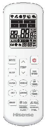
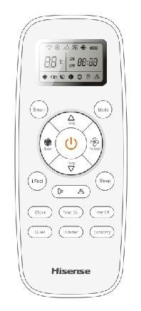
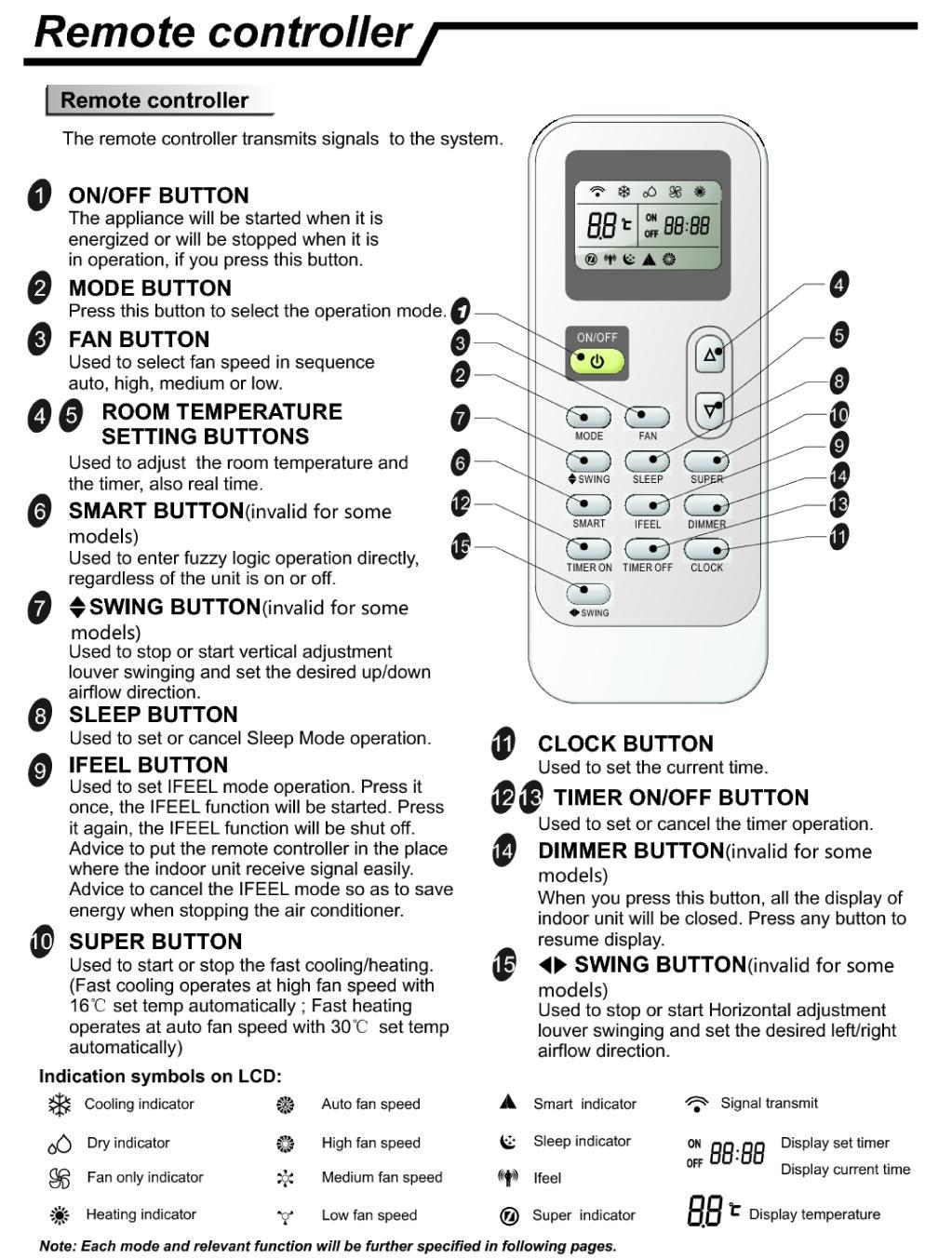
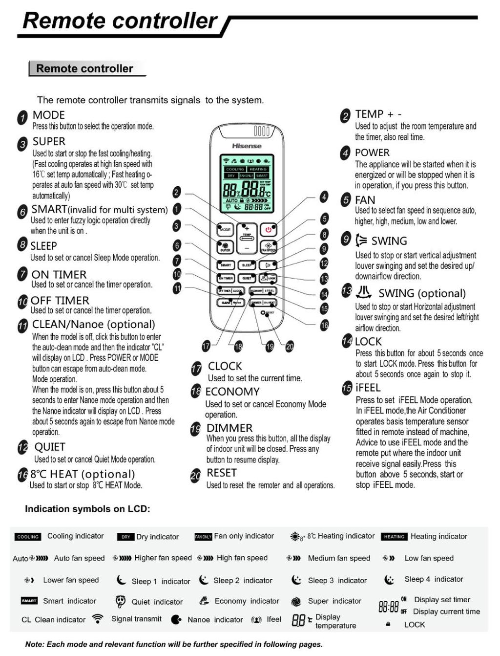
44 5. Function Operation 5-1. Operation Range (cooling and heating COOLING HEATING Temperature Indoor Air Intake Temp. Outdoor Air Intake Temp Maximum 32 D.B.23 W.B. 43 D.B.26 W.B. Minimum 21 D.B.15 W.B. -10 D.B.-11 W.B. Maximum 27 D.B.18 W.B. 24 D.B.18 W.B. Minimum 20 D.B 15 W.B -10 D.B.-11 W.B Remote Controller Operation & Function Remote Controller Instruction 44
45 L
46 J
47 R
48 R
49 Function Instruction 1 Major general technical parameters 1-1 Remote receiver distance front of the air conditioner : 8 m. 1-2 Remote receiver angle: Less than 60 degrees. 1-3 Temperature control accuracy: ± Time error: Less than 1%. 2. Functions of the controller 2-1 Display panel I. Control functions of the remote controller (See operating and installation manual) II. Display of the indoor unit Information on the screen: Displaying Scheme: 7-segment tube Display set temperature or indoor temperature, and display fault code in trouble indicating. An error code is displayed according to the signal from the indoor CPU. The error code will flash for 5 seconds while displayed. Running LED It is on during operation. It is flashing when the unit defrost. TIMER LED When the timer mode works, the LED will be lighted. Sleep LED When the sleep mode works, the LED will be lighted, and after 10s, the LED will be off. Compressor LED It lights up when compressor is running. Remote control receiver This section receives signals from the remote control. 3. Control function 3-1 Emergency switch If the appliance under the Stand-by state, all the Operation Mode, Air volume, Temperature Setting, Forced Cooling function will be restored as the last time setting when you press on the ONOFF button, but lost the Air flow direction setting. If the appliance was connected to the power at first time, it would operate in the auto mode, It will keep in stand-by state if you press the ONOFF button during the normal operation. When the appliance under the Stand-by state, press and hold the emergency switch for 5 seconds, the buzzer rings for 1 times, and it will operate in cooling mode, and the indoor fan speed is set to high-speed, it running has nothing to do with the room temperature. When press the emergency switch or receive the signal of the remote control, it will exit this mode, and it will operate with the corresponding order. 3-2 Operator-machine communication If the unit has I feel function, when the I feel function is set by the remote control, the room temperature will depend on the remote control and it will be detected by the sensor of the remote control. Normally the remote control will automatically transmits a signal at an interval of 10 minutes only for H1 remote control, it is 9 minutes, but if the room temperature changed exceed 1 in a short period of time, the remote control will transmits a signal within 2 minutes. If the indoor unit has not received a remote signal within 30 minutes, the room temperature will depend on the room temperature sensor of indoor unit. 49
50 3-3 Timer function Real time of Timer setting (1) The max Timer ranges is 24 hours. (2) Timer ONOFF (3) Timer ONOFF can be set available in turn. (4) The Timer accurate more than 97% (5) The Timer can be adjusted by 1 min increase. (6) The appliance can be set the ON-Timer and OFF-Timer in the same time, but no any timer setting indicated. 3-4 Sleep (1)The Sleep mode can only be set during Cool, Heat and Dry mode. (2)When the appliance run in the Sleep mode, it will stop after 8 hours operation, then it will cancel the Sleep setting. When the appliance operate under the OFF-Timer setting condition, if the OFF-Timer setting less than 8 hours, it will keep the Sleep mode till the OFF-Timer setting; if the OFF-Timer setting more than 8 hours, it will cancel the OFF-Timer setting after the Sleep mode OFF. (3)When the Sleep mode is select with Cooling mode, if the room temperature not less than 26, the setting temperature will not be adjusted, otherwise, the setting temperature will be raised by 1 per hour, but the max setting temperature raise is 1. (4)When the Sleep mode is select with Heat mode, the setting temperature will be decreased by 1 per hour during the successive 3 hour, but the max setting temperature decrease is 3. (5)When the appliance operate with Sleep mode, the indoor fan run in the LOW setting, and the air flow direction same as the last setting and the temperature and air flow direction can be adjusted by user. The Running indicator will be flashed 10 times per 1 Hz frequency, then all the indicators turn OFF except the Sleep light after 5 min elapse. Those indicators will be recovery when the temperature or Time setting is adjusted, after the setting, the indicators will be lit in 10 sec, then turn OFF. 3-5 Automatic run (SMART) mode When the appliance operates at the smart, the air flow direction can be adjusted. (1) HC appliance a. When the setting temperature is 26, the appliance will be ran in the Cool if the room temperature exceeds 26. b. When the room temperature exceeds 23, but below 26, it will be ran in the Dry mode(it will turn in Automatic setting After 3 min LOW air volume running.). c. When the room temperature exceeds 21, but below 23, it will be operated in the Fan only, the air volume is set by LOW and the fan speed can be adjusted d. When the room temperature is not more than 21, it will be operated in Heat mode, and the temperature is set to 22. (2) Cool only appliance a. When the room temperature exceeds 26, it will be ran in Cool mode, and the temperature is set to 26. b. When the room temperature exceeds 23, but not more than 26, it will be operated in the Dry mode. c. When the room temperature is not more than 23, it will be operated in the Fan only, the air 50
51 volume is set to LOW and the fan speed can be adjusted After the appliance start the smart operation, the setting temperature can be adjusted 2 or 7 (based on the remote mode)(the min accuracy is 1 ) up and down base on the automatic temperature setting, also the presetting temperature of PCB circuit. In case of the specific operation selected, it could be re-select the other modes after the compressor ceased for 5 min or the setting temperature changed. 3-6 Cooling-run mode Outdoor Fan The outdoor fan s speeds except the single speed motor can be changed according to outdoor ambient temperatures. When operating at a fixed frequency, the outdoor fan is forced to operate at the high speed Indoor fan operation (1 When the indoor fan keep in running condition, this operation state could be controlled by the remote control with High, Median, Low and Automatic setting. (2 When the appliance is set Automatic condition in the Cool mode for the first time, the fan speed will run at Low setting. After that, temperature and fan speed is shown as following. When the difference between the setting temperature and the room temperature equal to 2 or 4, the indoor fan speed will keep in current speed Air flow direction control The louver is derived by a step motor, and it swings the horizontal louver automatically. Press the SWING button to swing or stop the louver. During the louver swing in normal operation, the current position will be stored. When the appliance turn off and louver swing automatically to the default position, it will position at the close position plus 5º way valve State: It is interrupted in cooling. Switchover: When initially powered on for cooling, the 4-way valve is interrupted immediately. When the heating is changed to the cooling, it needs an interval of 50 seconds for the 4-way valve to 51
52 change over from being activated to being interrupted. 3-7 Heating-run mode Temperature compensation The temperature compensation is 5º in heating mode. For example, if the set temperature is 25 by the remote control, when the room temperature is detected with 31, the compressor will turn off. The main reason is that the hot air is condensed at the top of the house. Note: The compensation is available only if the room temperature sensor of indoor unit is used and it is not available when it is subject to the sensor on the remote control Indoor fan motor operation Anti-cold air system: When the appliance run in Heat mode condition, the indoor fan motor operation is shown as following to prevent the cooling air come out during the appliance operation. When the appliance turn in the anti-cold air system in the Extra-LOW (Tapped motor set in LOW, sic passim) during the compressor operation, the louver swang to the Cool air protection position, the louver recovers to the original position after the air volume change to LOW. When the room temperature reach to the setting temperature, the compressor will be turn off, and the air flow change to LOW, the louver swang to the Cool air protective position to prevent the air drop into human body directly; when the indoor pipe coil temperature drop continuously, it will turn in the Cooling air protective system in the Extra-LOW or stop the fan motor. The indoor fan motor is only controlled by the signal of indoor pipe coil temperature, no matter the compressor turn ONOFF, even the appliance turn in Heat mode at first time. The indoor fan motor will operate according to the different setting(high, Median, Low and Automatic) by the remote control, but the anti-cold air system is prior. When the appliance run in the Heat mode with the Automatic setting at first time, the fan speed will be in the LOW setting, and the operation diagram is shown as following 52
53 When the difference between the setting temperature and the room temperature equal to 2 or 4, the indoor fan speed will keep in current speed Air flow direction control The horizontal louver is controlled by a step motor, press the SWING button to swing or stop the louver. During the louver run in normal operation, the current position will be stored. When the appliance turn off and louver swing automatically to the default position, it will position at the default position plus 5º Outdoor fan The outdoor fan speeds except single speed motor can be changed according to outdoor ambient temperatures way valve State: It is electrified in heating. Switchover: When initially powered on for heating, the 4-way valve is activated immediately. In the change from cooling to heating, it needs an interval of 50 seconds for the 4-way valve to change over from being interrupted to being activated. 3-8 The super function (option) In cooling mode, when you press the SUPER button by remote control, the unit will operate for 15 minutes with the following setting: a. The set temperature is 16 ; b. The fan speed with highest speed; c. The compressor runs with high frequency. 3-9 Dehumidifying mode The dehumidifying mode is illustrated as follows: 53
54 Dehumidifying area I: Operation at the frequency in the range (30 60Hz) according to Dt (Tindoor ambient-tset). Dt( ) f(hz) Dehumidifying area II: The compressor stops for 5 minutes and operators for 5 minutes at the lowest frequency. Dehumidifying area III: The compressor stops Fan Only Mode Operation During the appliance run in this mode, the compressor and outdoor fan stop, the indoor fan operate under the pre-setting of air volume, and the louver swing, and the indoor fan speed same as the Heating Mode Special Function Fnstruction Conditions of anti-freezing prohibition of frequency rising: Condition 1: in the case of anti-freezing frequency decreasing, the temperature of indoor heat exchanger rises to 54
55 anti-freezing frequency decreasing temperature. Condition 2: in normal operation, the temperature of indoor heat exchanger reaches anti-freezing prohibition of frequency rising temperature. Either of the above two conditions is met, the product will enter anti-freezing prohibition of frequency rising state. Anti-freezing prohibition of frequency rising operation: the compressor is kept at the current frequency, which may decrease according to situations while cannot rise. The outdoor fan runs. Condition for the end of anti-freezing prohibition of frequency rising state: when the temperature of indoor heat exchanger rises to anti-freezing releasing temperature, the state of anti-freezing prohibition of frequency rising is released. Conditions for defrosting: A: When the heating compressor consecutively runs for 40 minutes (EEPROM setting value at the current operating mode); B:If the ambient temperature minus the temperature of coiled pipe is equal to or higher than six degrees centigrade (EEPROM setting value in the current operating mode); C:If the temperature of coiled pipe is equal to or lower than minus two degrees centigrade (EEPROM setting value in the current operating mode); If the above three conditions are met simultaneously, defrosting begins. Defrosting actions: The compressor stops, and the outdoor fan stops after delay of 30 seconds; in 50 seconds the four-way valve is power off; and in 10 seconds the compressor starts and runs at defrosting frequency. Conditions for ending defrosting: Defrosting is over if either of the below conditions is met. A The accumulated time of defrosting is longer than 12 minutes (EEPROM setting value in the current operating mode); B If the temperature of coiled pipe is equal to or higher than 14 degrees centigrade (EEPROM setting value in the current operating mode); Actions of exiting the defrosting state: The compressor stops, and 50 seconds later the four-way valve opens, and another 10 seconds later the compressor and outdoor fan restart and begin normal operation. 55
56 5-4. Performance Data Temperature charts cooling 130,00% 6,00 125,00% 5,00 120,00% 4,00 115,00% EER Capacity Ratio % cooling 110,00% 2,00 105,00% 1,00 100,00% 95,00% 3, , Outdoor Temp 100,00% 2,50 80,00% 2,00 COP Capacity Ratio % 3,00 60,00% 1,00 20,00% 0, ,50 40,00% Heating 120,00% 0,00% 30 Outdoor Temp Heating Indoor Temp DB 20 WB ,00 12 Outdoor Temp Outdoor Temp 56 12
57 EER cooling 4,00 3,50 3,00 2,50 2,00 1,50 1,00 0,50 0, Outdoor Temp Heating 120,00% 4,00 100,00% 3,00 80,00% COP Capacity Ratio % Heating 60,00% 40,00% 1,00 20,00% 0,00% Indoor Temp DB 20 WB15 2, , Outdoor Temp Outdoor Temp 57
58 6. Electrical Characteristics 6-1. Print Circuit Board (Indoor & Outdoor) Model Indoor unit Outdoor unit +AST-09UW4RXX** AST-12UW4RXX** AST-09UW4RXX**00A OU-PCB- RVERYD +AST-12UW4RXX**00A OU-PCB- RVERYD +AST-09UW4RXE** AST-12UW4RXE** AST-18UW4RXA** AST-18UR4RXA**00A AST-09UW4RVE** OU-PCB- RVERYD +AST-09UW4RVE**00B OU-PCB- RVERYD +AST-09UW4RVE**00A OU-PCB- RVERYD +AST-12UW4RVE** OU-PCB- RVERYD +AST-12UW4RVE**00B OU-PCB- RVERYD +AST-12UW4RVE**00A OU-PCB- RVERYD +AST-12UW4RVZ** OU-PCB- RVERYD OU-PCB- RVERYD +AST-24UW4RBB** AST-24UW4RBB**00A AST-24UW4RBB**00B AS-09UR4RYD** OU-PCB- RVERYD AS-12UR4RYD** OU-PCB- RVERYD AST-24UW4RDB** AST-24UW4RDB**00A AST-18UW4RBA** AST-18UW4RBA**00A AST-18UR4RXA**00 +AST-18UW4RXA**00B +AST-09UW4RYD**00 +AST-09UW4RYY**00 Note: ** mean code of Front Panel. 58
59 Model of indoor unit: Interface of PG motor(white) Room temperature sensor(red) Pipe temperature sensor(white) Switch button Feedback from PG motor(white) Up down swing(white) Left right swing(black) Wiring control or wifi interface Display interface Protective tube Feedback from PG motor(white) Up down swing(white) Left right swing(black) Display interface 9 Protective tube Interface of PG motor(white) Room temperature sensor(red) Pipe temperature sensor(white) Switch button
 Room temperature sensor(red) Pipe temperature")
 Room temperature sensor(red) Pipe temperature sensor(white)")
60 Up down swing(white) Left right swing(black) Display interface 9 Protective tube Interface of DC motor(white) Room temperature sensor(red) Pipe temperature sensor(white) Switch button 8 Up down swing(white) Left right swing(black) Display interface 9 Protective tube Interface of DC motor(white) Room temperature sensor(red) Pipe temperature sensor(white) Switch button
61 Interface of DC motor(white) Room temperature sensor(yellow) Pipe temperature sensor(black) wifi interface 6 Up down swing(white) Display interface 7 Protective tube Feedback from PG motor (WHITE) Up down swing(white) 7 Left right swing(black) 8 Wiring control or wifi interface Display interface Interface of PG motor(white) Room temperature sensor(red) Pipe temperature sensor(white) Switch button Humidity detection interface(white) Protective tube
 Room temperature sensor(yellow) Pipe temperature sensor(black) wifi interface Interface of PG motor(white) Room temperature sensor(yellow) Pipe temperature sensor(black)")
62 Up down swing(white) Display interface 7 Protective tube 8 Wiring control interface(white) OUT INPUT interface(red) EPROM PROGRAM interface(red) Interface of DC motor(white) Room temperature sensor(yellow) Pipe temperature sensor(black) wifi interface Interface of PG motor(white) Room temperature sensor(yellow) Pipe temperature sensor(black) Switch button Feedback from PG motor(white) Up down swing(white) Left right swing(black) Wiring controlinterface (WHITE) Display interface 10 Protective tube 11 Wificontrolinterface
 Left right swing(black) Wifi controlinterface Wiring controlinterface (WHITE) Display interface Protective")
63 Interface of DC motor (WHITE) Room temperature sensor(yellow) Pipe temperature sensor(black) Switch button Up down swing(white) Left right swing(black) Wifi controlinterface Wiring controlinterface (WHITE) Display interface Protective tube
\" BROWN Terminal of signal wire,connect to the terminal panel \"3(SI)\" RED 6 Terminal of AC fan cool valve terminal WHITE 7 Cool Valve 12 terminal WHITE 8")
64 Model of outdoor unit: Terminal of compressor UVW phase REDWHITEBLUE 2 Terminal of reactor BROWNORANGE Terminal of nuetral wire,connect to the terminal panel "1(N) " (BLUE Terminal of live wire,connect to the terminal panel "2(L)" BROWN Terminal of signal wire,connect to the terminal panel "3(SI)" RED 6 Terminal of AC fan cool valve terminal WHITE 7 Cool Valve 12 terminal WHITE 8 Heater terminal(red) way valve terminal(black) Terminal of DC fan WHITE Terminal of electronic expansion valve WHITE 16 Over pressure sensor WHITE Outdoor ambient temperature sensor(yellow) 17 DRED Function Outdoor pipe temperature sensor(black) 18 Compressor discharge temperature sensor WHITE Terminal of compressor overload protector(red) 19
 Heat terminal (RED) Terminal of signal wire,connect to the terminal panel \"3(SI)\" Terminal of nuetral wire,connect to the terminal panel \"1(N)\" Terminal of reactor 2 Terminal of DC")
65 OU-PCB- RVERYD Terminal of compressor UVW phase REDWHITEBLUE Compressor discharge temperature sensor(white) Outdoor pipe temperature sensor(black) Terminal of electronic expansion valve(white) Heat terminal (RED) Terminal of signal wire,connect to the terminal panel "3(SI)" Terminal of nuetral wire,connect to the terminal panel "1(N)" Terminal of reactor 2 Terminal of DC fan(white) 4 8 Outdoor ambient temperature sensor(yellow) Terminal of compressor overload protector(red) Terminal of AC fan(white) 10 4-way valve terminal(black) 12 Terminal of live wire,connect to the terminal panel "2(L)" Terminal of earth wire
66 Terminal of compressor U phase(red) Terminal of compressor V phase(white) Terminal of compressor W phase(blue) Terminal of reactor Terminal of reactor Terminal of nuetral wire with filter board Terminal of compressor overload protector(red) Compressor discharge temperaturesensor(white) Terminal of live wire with filter board Terminal of AC fan (WHITE) Terminal of heater(red) Terminal of 4-way valve(black) Terminal of communication with wire filter Terminal of communication with wire filter Terminal of electronic expansion valve(white) Outdoor ambient temperature sensor(yellow) 17 Outdoor pipe temperature sensor(black) 18 Terminal of DC fan(white)
67 Llive wire to terminal block Nuetral wire to terminal block Communication wire to terminal block Terminal of communication to driver-board Terminal of nuetral wire to driver-board Terminal of live wire to driver-board Terminal of ground wire
 Terminal of 15 compressor V phase(white) Outdoor pipe 3 temperature sensor(black) 4-way valve 7 terminal(black) Terminal of nuetral 11 wire with filter")
68 Terminal of DC 1 fan(white) Terminal of compressor 5 overload protector(red) Compressor discharge 2 temperature sensor(white) Terminal of electronic 6 expansion valve(white) Terminal of live wire 10 with filter board(black) Terminal of 15 compressor V phase(white) Outdoor pipe 3 temperature sensor(black) 4-way valve 7 terminal(black) Terminal of nuetral 11 wire with filter board(white) Terminal of 16 compressor U phase(red) Outdoor ambient 4 temperature sensor(yellow) 8 Terminal of AC fan(white) Terminal of communication wire 9 with filter board(redwhite) 12,13 68 Terminal of reactor BROWNORANGE Terminal of 14 compressor W phase(blue)
69 Terminal of live 1 wire,connect to the driver board(black) Terminal of nuetral 2 wire,connect to the driver board(white) Terminal of communication 3 wire,connect to the driver board(redwhite) Terminal of signal 4 wire,connect to the terminal panel "3(SI)"(RED) 5 Terminal of ground wire(yellowgreen) Terminal of nuetral 6 wire,connect to the terminal panel "1(N)"(BLUE) 69 Terminal of live wire,connect to the 7 terminal panel "2(L)"(BROWN)
70 Terminal of live 1 wire,connect to the driver board(black) Terminal of signal wire,connect to the 4 terminal panel "4(SI)"(RED) Terminal of nuetral 2 wire,connect to the driver board(white) 5 Terminal of communication 3 wire,connect to the driver board(redwhite) Terminal of ground wire(yellowgreen) Terminal of nuetral wire,connect to the 6,7 terminal panel "N" and "2(N)"(BLUE) 70 8,9 10 or 11 Terminal of live wire,connect to the terminal panel "L" and "1(L)"(BROWN) Terminal of live wire,connect to the terminal panel "0(L)"(BROWN)
71 Terminal of compressor UVW phase(redwhiteblue) 5 Terminal of 6 reactor(brownorange) Terminal of nuetral wire,connect to the terminal panel "1(N)"(BLUE) Terminal of live wire,connect to the terminal panel "2(L)"(BROWN) 9 4-way valve terminal(black) 10 Terminal of electronic expansion valve(white) Terminal of cool valve reactor(brownorange) terminal(white) Terminal of signal 4 wire,connect to the terminal 8 panel "3(SI)"(RED) Terminal of AC fan(white) Terminal of compressor 14 overload protector(red) Outdoor ambient temperature 15 sensor(yellow) Outdoor pipe temperature sensor(black) Compressor discharge temperature sensor(white) 16 Over pressure Sensor(WHITE) Terminal of DC fan(white)
72 OU-PCB-SYDSVE 1 Terminal of compressor U phase(red) Terminal of compressor V phase(white) Terminal of compressor W phase(blue) Terminal of DC fan(white) Terminal of electronic expansion valve(white) Terminal of compressor overload protector(red) Compressor discharge temperaturesensor(white) Terminal of AC fan (WHITE) Outdoor pipe temperature sensor(black) Outdoor ambient temperature sensor(yellow) Terminal of 4-way valve(black) Terminal of heater(red) communication wire to terminal block 14 Terminal of nuetral wire to terminal block 15 Terminal of live wire to terminal block 16 Terminal of ground wire Terminal of reactor Terminal of reactor
73 Terminal of reactor 2 Terminal of compressor (WHITE) 3 Terminal of DC fan (WHITE) 4 Heat Sink temperature sensor (WHITE) 6 Compressor discharge temperature sensor (YELLOW) 11 DRED Function 7 Outdoor ambient temperature sensor (WHITE) 12 Terminal of AC fan (WHITE) 8 Outdoor pipe temperature sensor (RED) 13 Cool Valve terminal 18 9 PressureProtector 5 10 (BLACK) Terminal of compressor overload protector (WHITE) Terminal of electronic expansion valve (WHITE) Heater terminal 15 4-way valve terminal (BLACK) Terminal of communication wire Terminal of live wire Terminal of nuetral
74 6-2. Fan Motor Drawings attached: DG13G1-16 DG13G2-07 Test in resistance. TOOL: Multimeter. Test the resistance of the main winding. The indoor fan motor is fault if the resistance of main winding 0(short circuit)or open circuit. Test in voltage TOOL: Multimeter. Insert screwdriver into to rotate indoor fan motor slowly for 1 revolution or over, and measure voltage YELLOW and GND on motor. The voltage repeat 0V DC and 5V DC. Notes: 1) Please don t hold motor by lead wires. 2) Please don t plug INOUT the motor connecter while power ON. 3) Please don t drop hurl or dump motor against hard material. Malfunction may not be observed at early stage after such shock. But it may be found later, this type of mishandling void our warranty. 74
75 Indoor DC Fan Motor Outdoor DC Fan Motor 6-3. Temperature Sensor Parameter table attached: 1. THE PARAMETER OF THE INDOOR COIL AND INDOOR ROOM SENSOR,THE PARAMETER OF THE OUTDOOR COIL AND OUTDOOR SENSOR: R(0)=15k B(0100)=3450 Temperature( ) Resistance(k) Voltage(V) Temperature( ) Resistance(k) Voltage(V)
76 Note: the AD value in the table is calculated on the basis of the pull-down resistor is 5.1K. 76
77 2. THE PARAMETER OF OUTDOOR COMPRESSOR TEMPERATURE SENSOR R(0)=187.25k Temperature B(0100)=3979) Temperature Resistance ( ) (k) Resistance(k) Voltage(V) ( ) 77 Voltage(V)
78 Note: the AD value in the table is calculated on the basis of the pull-down resistor is 6.8K. 78
79 6-4. Compressor Drawings attached: OVERLOAD PROTECTION POWER DC INVERTER & CONTROLLER R( U) S( V) T( W) Test in resistance. TOOL: Multimeter. Test the resistance of the winding. The compressor is fault if the resistance of winding 0(short circuit)or open circuit Familiar trouble: 1)Compressor motor lock. 2 Discharge pressure value approaches static pressure value.3)compressor motor winding abnormality. Notes 1 Don t put a compressor on its side or turn over. 2) Please assembly the compressor in your air conditioner rapidly after removing the plugs.don t place the comp. In air for along time. 3) Avoiding compressor running in reverse caused by connecting electrical wire incorrectly. 4) Warning! In case AC voltage is impressed to compressor, the compressor performance will belower because of its rotor magnetic force decreasing Electric Reactor Drawings attached: L Familiar error: 1 Sound abnormality 2 Insulation resistance disqualification. 79


 Fig.")
80 6-6. Room Card Control, Fire Protection, ONOFF Function Setting method of Room Card Control and ONOFF Function This machine defaults that the room card control is effective, which can be switched between the room card control and ONOFF function through wire controller. The specific operations are as follows: Fig. 1 Fig.2 YXE-C01U YXE-C02U(E) Fig.3 YXE-D01U(E) Fig.4 YXE-A03U(E) The EE address number of ONOFF function is 25 first enter the parameter number 17, and then adjust to the EE address number
81 Exhibit 1: Built-in EE settings combination SN Byte EE settings combination data Function Remark Function code The room card control or the fire protection is enabled, while ONOFF function is not enabled 4 ONOFF function is enabled, while room card control or the fire protection is not enabled Reading and writing EE operations through wire remote controller are as follows: (1) Operations: In any state, hold down both MODE button and ADD.FUNC. button for 3 seconds to enter read and write parameters. Result: The buzzer makes a functional sounds. On display screen, the symbol and the parameter number flash at the same time. Note: For YXE-D01U(E), replace ADD.FUNC. button with FUNC button. Note: For YXE-A03U(E), replace ADD.FUNC. button with Fan speed button. (2) Operations: In a state of that, The symbol and the parameter number flash at the same time press button or button Result: On display screen, the parameter number increases or decreases by 1 correspondingly (0-25), and the parameter data changes correspondingly. (3) Operations: In a state of that, the symbol and the parameter number 17 flash at the same time press ENTER button to enter the EE reading. Result: On display screen, the symbol does not flash, and the EE address flashes. Note: For YXE-A03U(E), replace ENTER button with Timer button. (4) Operations: In a state of that, the symbol does not flash, and the EE address flashes, press button or button. Result: On display screen, the EE address increases or decreases by 1 (0-255) correspondingly, and the parameter data changes correspondingly. (5) Operations: In a state of that, the symbol does not flash, and the EE address number 25 flash, press ENTER button to enter the EE writing. Result: On display screen, the symbol and the EE address number 25 do not flash, and the function code corresponding to the EE address flashes. Note: For YXE-A03U(E), replace ENTER button with Timer button. (6) Operations: In a state of that, the symbol and the EE address number 25 do not flash, and the function code corresponding to the EE address flashes, press button or button. Result: On display screen, the function code corresponding to the EE address increases or decreases by 1. (7) Operations: In a state of that, the symbol and the EE address number 25 do not flash, and the 81


 function, use the wire controller to modify the parameters of indoor unit. 2.")
 Fire protection: a kind of control mode to control the machine startup & shutdown based on the on & off state of the fire protection port.")
82 function code corresponding to the EE address flashes, press ENTER button. Result: On display screen, the symbol does not flash, and the EE address number 25 flashes to display the function code of EE after modification. Note: For YXE-A03U(E), replace ENTER button with Timer button. (8) Press ONOFF button or CANCEL button to exit. Note: For YXE-A03U(E), Press ONOFF button to exit Instructions for the function setting of room card control, fire protection, ONOFF function. 1. Factory setting ONOFF function is tacitly approved to be invalid when out of factory while both the room card control and fire protection functions are valid. In case of using or cancelling the room card control fire protection (ONOFF) function, use the wire controller to modify the parameters of indoor unit. 2. Function introduction (1) Room card control: a kind of control mode to control the machine startup & shutdown based on the on & off state of the room card control port. (2) Fire protection: a kind of control mode to control the machine startup & shutdown based on the on & off state of the fire protection port. (3) ONOFF function: a kind of special control mode to achieve the control of indoor unit startup & shutdown based on the input state of the fire protection port of the indoor unit (no other way can control startup & shutdown) and output the fault status of indoor unit through OUT INPUT port. 3. Function setting 3.1 Hardware connection Fig.1 electrical wiring diagram Fig.3 main control board Fig.2 short wiring Fig.4 output line 82
, and the OUT INPUT CN16 socket of main control board is shown as Figure 3. (Illustration: the socket number in circuit is subject to the actual serial number of PCB.")
83 3 pins of the OUT INPUT CN16 socket shown in the electrical wiring diagram of Figure 1 are tacitly approved to be in short circuit state under the factory state (an external short circuit plug shown as Figure 2), and the OUT INPUT CN16 socket of main control board is shown as Figure 3. (Illustration: the socket number in circuit is subject to the actual serial number of PCB.) 1) When using the room card control or fire protection, the user cuts off the short wire shown in Figure 2 and connects the red line and the black line to the control switch (supplied by user), and the connecting wire should be 22AWG or above specification. The switch is closed under normal conditions and off under abnormal conditions. 2) When using the ONOFF function, the user cuts off the short wire shown in Figure 2 and connects the black line and the white line to the ONOFF control switch (supplied by user), and the connecting wire should be 22AWG or above specification. In normal conditions, the machine starts once the switch is closed and the machine shuts down once the switch is off. Fig.5 Hardware connection diagram 3.2 Timing sequence description: (1) Room card control: 1) Control of room card disconnection: the air conditioner shall be shut down after the room card control signal is disconnected. In this state, the indoor unit can t be started. If the user performs starting operation, the wire controller shall not respond and displays power-off. 2) Control of room card connection: after the short circuit of room card control interface, release power-on restrictions, the wire controller maintains power-off and the startup & shutdown control is effective. (2) Fire protection 83
84 1) Access to fire protection: the air conditioner shall be shut down after the fire protection signal is disconnected. In this state, the indoor unit can t be started. If the user performs starting operation, the wire controller shall not respond and displays power-off. 2) Cancellation of fire protection: after the short circuit of fire protection signal, release power-on restrictions, the wire controller maintains power-off and the startup & shutdown control is effective. (3) ONOFF function 1) In the situation where ONOFF function is effect, the port is closed and in short circuit, the indoor unit starts; the indoor unit shuts down once the port is disconnected; 2) Other operation information (such as mode, air speed, air door, etc.) except for startup & shutdown can be set through the wire controller, remote-controller and WIFI module; 3) In the mode of ONOFF function, wire controller, remote-controller, WIFI module and room card control cannot control the machine startup & shutdown, and nor can in the mode of the timing or sleep function. 4) There will be 12V signal output when machine fault occurs. 3.3 Relative priorities of instructions ONOFF function has the highest priority. The room card control shall be invalid when ONOFF function is effective. The room card control and fire protection can not be selected at the same time, only one can be selected Wiring Remote Controller Model Installation Manual Use And Installation Instructions YXE-C01U YXE-D01U(E) YXE-C02U(E) YXE-A03U(E) Not available Note: Installation Manual and Use And Installation Instructions are separate documents. 84
85 7.Trouble Shooting 7-1. Error Code Table 1.Indication on the outdoor unit: When the unit has the following trouble and the compressor stops running, The LED of outdoor control board will show the error sequence automatically: NOTE: LIGHT O FLASH OFF Error Outdoor Failure the root cause my be one of the following LED1 LED2 LED3 code Description Mark description: the lights flash every second for the following faults Normal Outdoor coil temperature sensor in trouble Compressor exhaust temperature sensor in trouble Communication failure between the indoor unit and outdoor unit Current overload protection O a.the outdoor coil sensor connect loose; b.the outdoor coil temperature sensor is failure; c.the outdoor control board is failure a.the compressor exhaust temperature sensor connect loose; b.the compressor exhaust temperature sensor is failure; c.the outdoor control board is failure O a.the communication cable connect loose; b.the communication cable is failure; c.the connection between the filter board and the outdoor control board is incorrect or loose; d.the connection between the filter board and the terminal is incorrect or loose; e.the indoor control board is failure; f.the PFC board is failure; g.the power board is failure; h.the outdoor control board is failure. a.the fan motor run abnormally; b.the condensor and evaporator is dirty; c.the air inlet and outlet is abnormally Maximum current protection O a.the outdoor control board is short circuit; b.the drive board is short circuit; c.the other components is short circuit Communication trouble between outdoor unit and driver a. the connection wires connect loose b.the outdoor board or drive board is failure; 85
86 Outdoor EEPROM in trouble Compressor exhaust temperature too high protection Outdoor ambient temperature sensor in trouble Compressor shell temperature too high protection Anti-freeze protection with cooling or overload protection with heating in indoor unit Compressor drive in trouble Outdoor fan motor locked rotor protection Outdoor coil anti-overload protection with cooling O O O O O a.the EEPROM chip is loose; b.the EEPROM chip inserted with opposite direction; c.the EEPROM chip is failure a.the compressor exhaust temperature sensor is failure; b.the refrigerant of the unit is not enough a.the outdoor ambient temperature sensor connect loose; b.the outdoor ambient temperature sensor is failure; c.the outdoor control board is failure O a.the compressor exhaust temperature sensor connect loose b.the refrigerant of the unit is not enough O a.the indoor coil temperature sensor connect loose; b.the indoor coil temperature sensor is failure; c.the indoor control board is failure d. the refrigerant system is abnormal. O a.the outdoor drive board is failure; b.the compressor is failure c. the outdoor control board is failure a.the connection of the outdoor fan motor is loose; b.there are something block the outdoor fan; c.the fan motor is failure; d.the outdoor control board is failure a.the refrigerant is too much; b.the outdoor fan motor is failure; c.the outdoor fan is broken; d.the condensor is dirty; e.the air inlet and air outlet of the indoor unit and the outdoor unit is not normally 86
87 IPM module protection O a.the IPM board is failure; b.the outdoor fan is broken; c.the outdoor fan motor is failure; d.the outdoor fan has been blocked ; e.the condenser is dirty; f.the outdoor unit has been installed without standard. PFC protection O a.the PFC is failure; b.the outdoor drive board is failure Compressor pre O O it is normal mode in cold weather heating process Chip in outdoor a. Using the wrong drive board; O board in trouble b. Using the wrong compressor. AC voltage higher a.the supply voltage is higher or lower than normal; O or lower b.the inner supply voltage of the unit is higher or protection lower than normal DC compressor a.the outdoor drive board is failure; O O start failure b.the compressor is failure Outdoor ambient O O a Outdoor ambient temperature too low temperature too low protection Mark description: the lights flash every two seconds for the following faults a. Radiator sensors fail Protection against b. Detection circuit of the sensor on the overheated control panel fails outdoor radiator a. The pressure switch fails b. The pressure detection switch on the control Protection of the panel fails system against too c. The measured value of the system pressure high pressure exceeds the limit When the compressor is in operation: Flash Off; the flash cycle is 1S Mark description: Light No. LED1 LED2 LED3 1 2 Frequency decreasing or prohibition frequency rising caused by over-current 3 Frequency decreasing or prohibition of frequency rising caused by anti-freezing of refrigeration or anti-overload in heating 4 Frequency decreasing or prohibition of frequency rising caused by too high compressor discharge temperature Reasons for the current operating frequency of the compressor is limited Normal frequency rising and decreasing, no limitation 87 of
88 5 Limit to the max operating frequency caused by too low power voltage 6 Operation at fixed frequency (in the case of capability measuring or compulsory operation at fixed frequency) 7 Protective frequency decreasing against outdoor overload (overpower, over frequency conversion rate, over torque, detection of DC under-voltage) 8 Frequency decreasing caused by indoor and outdoor communication fault 9 Frequency decreasing or prohibition of frequency rising protection against overload of outdoor coiled pipe 10 Frequency decreasing or prohibition of frequency rising for power-saving when it is being used simultaneously with other appliances 2.Indication by the indoor unit: 2.1. The 7-segment tube of the indoor display board will show the error code automatically when the unit has the following trouble: o Flash x OFF Error Power Timer Running Sleep Remark Light code The root cause is may be Content Remark one of the following the error code a. The connection between will display when the the display board and control communication board is loose; EA between display b. The indoor control board board and is failure. control board c.the wiring of the display have in trouble board is failure. 2.2.When the unit has the following trouble and the compressor stops running, press the sleep button on the remote controller for 10 times in ten seconds and the 7-segment tube of the display board will show the error code as the following, if two malfunction happened at the same time, it need press the sleep button for 10 times again, the LED will show the other error code. Refer to the remote controller which the sleep key can set into 4 different combination ways (Hisense's new design remote controller), when using to check the error codes only takes effect for pressing the sleep key 10 times in ten seconds instead of 4 times. NOTE: If the troubleshooting inquiry display by 7-segment tube, then the error code will be displayed, otherwise only the LED of the display board can show. Error code 0 Running Timer Sleep Power Remark Light Content Normal 88 o Flash Remark x OFF The root cause is may be one of the following
89 1 x o x x Compressor exhaust temperature sensor in trouble 2 IPM module protection 5 AC voltage higher or lower protection 6 Communication failure between the indoor unit and outdoor unit 7 8 The failure for temperature sensor of outdoor coil Current overload protection 89 a. The outdoor temperature sensor loose; b. The outdoor temperature sensor is failure; c. The indoor control board is failure a.the compressor exhaust temperature sensor connect loose; b.the compressor exhaust temperature sensor is failure; c.the outdoor control board is failure a.the IPM board is failure; b.the outdoor fan is broken; c.the outdoor fan motor is failure; d.the outdoor fan has been blocked ; e.the condenser is dirty; f.the outdoor unit has been installed without standard. a.the supply voltage is higher or lower than normal; b.the inner supply voltage of the unit is higher or lower than normal a.the communication cable connect loose; b.the communication cable is failure; c.the connection between the filter board and the outdoor control board is incorrect or loose; d.the connection between the filter board and the terminal is incorrect or loose; e.the indoor control board is failure; f.the PFC board is failure; g.the power board is failure; h.the outdoor control board is failure. a.the fan motor run abnormally; b.the condensor and evaporator is dirty; c.the air inlet and outlet is
90 abnormally Communication trouble between outdoor unit and driver a. the connection wires connect loose b.the outdoor board or drive board is failure; Outdoor EEPROM in trouble a.the EEPROM chip is loose; b.the EEPROM chip inserted with opposite direction; c.the EEPROM chip is failure Outdoor ambient temperature too low protection Compressor exhaust temperature too high protection Outdoor ambient temperature sensor in trouble Maximum current protection a.the outdoor control board is short circuit; b.the drive board is short circuit; c.the other components is short circuit Compressor shell temperature too high protection Anti-freeze protection with cooling or overload protection with heating in 90 Outdoor ambient temperature too low a.the compressor exhaust temperature sensor is failure; b.the refrigerant of the unit is not enough a.the outdoor ambient temperature sensor connect loose; b.the outdoor ambient temperature sensor is failure; c.the outdoor control board is failure a.the compressor exhaust temperature sensor connect loose b.the refrigerant of the unit is not enough a.the indoor coil temperature sensor connect loose; b.the indoor coil temperature sensor is failure; c.the indoor control board is failure d. the refrigerant system is abnormal.
91 17 PFC protection 18 DC compressor start failure Compressor drive in trouble 19 a.the PFC is failure; b.the outdoor drive board is failure a.the outdoor drive board is failure; b.the compressor is failure a.the outdoor drive board is failure; b.the compressor is failure c. the outdoor control board is failure a.the connection of the outdoor fan motor is loose; b.there are something block the outdoor fan; c.the fan motor is failure; d.the outdoor control board is failure a.the refrigerant is too much; b.the outdoor fan motor is failure; c.the outdoor fan is broken; d.the condensor is dirty; e.the air inlet and air outlet of the indoor unit and the outdoor unit is not normally 20 Outdoor fan motor locked rotor protection 21 Outdoor coil anti-overload protection with cooling 22 Compressor pre heating process it is normal mode in cold weather 24 Chip in outdoor board in trouble a. Using the wrong drive board; b.using the wrong compressor. 26 Overheated outdoor radiator 27 Protection against too high system pressure 33 The failure for temperature sensor of indoor room o x x 91 a. Radiator sensor fails b. Detection circuit of the sensor on the control panel fails a. The pressure switch fails b. The pressure detection switch on the control panel fails c. The measured value of system pressure exceeds the limit a. The indoor room temperature sensor loose; b. The indoor room temperature sensor is
92 o x x 34 The failure for temperature sensor of indoor coil temperature 36 Communication failure between the indoor unit and outdoor unit 38 Indoor EEPROM failure Indoor fan motor run abnormally The failure for Indoor grounding protective o o x o failure; c. The indoor control board is failure. a. The indoor coil temperature sensor loose; b. The indoor coil temperature sensor is failure; c. The indoor control board is failure. a.the communication cable connect loose; b.the communication cable is failure; c.the connection between the filter board and the outdoor control board is incorrect or loose; d.the connection between the filter board and the terminal is incorrect or loose; e.the indoor control board is failure; f.the PFC board is failure; g.the power board is failure; h.the outdoor control board is failure. a. The EEPROM chip loose; b. The indoor control board is failure a. There are something block the indoor fan motor; b. The fan motor cord connect loose; c. The fan motor is failure; d. The indoor control board is failure The indoor control board is failure 2.2 LED display Error code 0 Sleep Timer Running Remark Light Flash x OFF The root cause is may be one of Remark the following Content Normal 92
93 1 x x 2 x x x Compressor exhaust temperature sensor in trouble IPM module protection 5 7 The failure for temperature sensor of outdoor coil AC voltage higher or lower protection Communication failure between the indoor unit and outdoor unit Current overload protection Maximum current protection 93 d. The outdoor temperature sensor loose; e. The outdoor temperature sensor is failure; f. The indoor control board is failure a.the compressor exhaust temperature sensor connect loose; b.the compressor exhaust temperature sensor is failure; c.the outdoor control board is failure a.the IPM board is failure; b.the outdoor fan is broken; c.the outdoor fan motor is failure; d.the outdoor fan has been blocked ; e.the condenser is dirty; f.the outdoor unit has been installed without standard. a.the supply voltage is higher or lower than normal; b.the inner supply voltage of the unit is higher or lower than normal a.the communication cable connect loose; b.the communication cable is failure; c.the connection between the filter board and the outdoor control board is incorrect or loose; d.the connection between the filter board and the terminal is incorrect or loose; e.the indoor control board is failure; f.the PFC board is failure; g.the power board is failure; h.the outdoor control board is failure. a.the fan motor run abnormally; b.the condensor and evaporator is dirty; c.the air inlet and outlet is abnormally a.the outdoor control board is short circuit; b.the drive board is short circuit; c.the other components is short
94 circuit x x x x x x Communication trouble between outdoor unit and driver a. the connection wires connect loose b.the outdoor board or drive board is failure; Outdoor EEPROM in trouble a.the EEPROM chip is loose; b.the EEPROM chip inserted with opposite direction; c.the EEPROM chip is failure Outdoor ambient temperature too low protection Compressor exhaust temperature too high protection Outdoor ambient temperature too low a.the compressor exhaust temperature sensor is failure; b.the refrigerant of the unit is not enough Outdoor ambient temperature sensor in trouble a.the outdoor ambient temperature sensor connect loose; b.the outdoor ambient temperature sensor is failure; c.the outdoor control board is failure Compressor shell temperature too high protection a.the compressor exhaust temperature sensor connect loose b.the refrigerant of the unit is not enough a.the indoor coil temperature sensor connect loose; b.the indoor coil temperature sensor is failure; c.the indoor control board is failure d. the refrigerant system is abnormal. 16 x Anti-freeze protection with cooling or overload protection with heating in 17 x x PFC protection a.the PFC is failure; b.the outdoor drive board is failure 18 x DC compressor start failure a.the outdoor drive board is failure; b.the compressor is failure 94
95 x Compressor drive in trouble 19 x 20 Outdoor fan motor locked rotor protection 21 Outdoor coil anti-overload protection with cooling x x a.the outdoor drive board is failure; b.the compressor is failure c. the outdoor control board is failure a.the connection of the outdoor fan motor is loose; b.there are something block the outdoor fan; c.the fan motor is failure; d.the outdoor control board is failure a.the refrigerant is too much; b.the outdoor fan motor is failure; c.the outdoor fan is broken; d.the condensor is dirty; e.the air inlet and air outlet of the indoor unit and the outdoor unit is not normally 22 Compressor pre heating process it is normal mode in cold weather 24 Chip in outdoor board in trouble a. Using the wrong drive board; b.using the wrong compressor. 26 Overheated outdoor radiator 27 Protection against too high system pressure 33 The failure for temperature sensor of indoor room The failure for temperature sensor of indoor coil temperature x Communication failure between 95 a. Radiator sensor fails b. Detection circuit of the sensor on the control panel fails a. The pressure switch fails b. The pressure detection switch on the control panel fails c. The measured value of system pressure exceeds the limit d. The indoor room temperature sensor loose; e. The indoor room temperature sensor is failure; f. The indoor control board is failure. d. The indoor coil temperature sensor loose; e. The indoor coil temperature sensor is failure; f. The indoor control board is failure. a.the communication cable connect loose;
96 the indoor unit and outdoor unit x x x Indoor EEPROM failure Indoor fan motor run abnormally The failure for Indoor grounding protective b.the communication cable is failure; c.the connection between the filter board and the outdoor control board is incorrect or loose; d.the connection between the filter board and the terminal is incorrect or loose; e.the indoor control board is failure; f.the PFC board is failure; g.the power board is failure; h.the outdoor control board is failure. c. The EEPROM chip loose; d. The indoor control board is failure b. There are something block the indoor fan motor; b. The fan motor cord connect loose; c. The fan motor is failure; d. The indoor control board is failure The indoor control board is failure The failure is detected when the room temperature sensor broken or shorted over 5 sec. The failure is detected when the temperature sensor of heater exchange broken or shorted over 5 sec. The failure is detected when each setting data is not match after the EEPPOM self-check two times. The failure is occur when the grounding signal is not detected after the appliance power ON. 96

97 7-2. Test the jumper terminals Note: When the whole machine is powered up, if the external unit does not work, to rule out the communications failures, adopt screening method such as short circuit on the jumper terminals to see if the external unit can be started normally or similar method. There are two blue terminals on the outdoor control panel, as shown above. Application: Short out the terminals, and power up the outdoor unit, then the outdoor unit may run independently. It can be determined that there is no internal and external communication faults. When the environment temperature is lower than 18, you can't run the unit under the cool mode, but if you need run the unit at this monnent,such as add the gas or do mose test, at this moment you can use this function, Umder this function, the outdoor motor and compressor will be forced to run until reaching a fixed frequenency (general is 50~55Hz) Trouble Diagnosis of Protection Protection diagnosis of the complete machine (all types of protection during operation, i.e. under-voltage, over-voltage and overcurrent protection) Note:List all types of protection that may occur to the complete machine and describe the conditions and signs of the start, course and end of such protection. Voltage protection Protection against AC input over-voltageunder-voltage 1.Conditions for protection against AC input over-voltageunder-voltage: If the input AC voltage is greater than protective over-voltage value or less than protective under-voltage value for five seconds, over-voltageunder-voltage protection tarts. 2.Protection actions against AC input over-voltageunder-voltage The system stops operation. 3. Conditions for ending AC input over-voltageunder-voltage: If the input AC voltage is lower than the protective over-voltage value -10V, or higher than the protective under-voltage value +10V, the over-voltageunder-voltage protection will be released. Current protection: 1.Protection against over-current Conditions for over-current protection: if the current is equal to or greater than current value for starting the refrigeration current protection (E2 value) for six seconds, over-current protection starts. Protection actions against over-current: indoor display screen and outdoor indicator give indications, the 97
SERVICE MANUAL OUTDOOR UNIT. No. OBH789
 OUTDOOR UNIT SERVICE MANUAL HFC utilized R32. Models MUZ-AP25VG - E1, ET1 MUZ-AP25VGH - E1 MUZ-AP35VG - E1, ET1 MUZ-AP35VGH - E1 MUZ-AP42VG - E1, ET1 MUZ-AP42VGH - E1 MUZ-AP50VG - E1, ET1 MUZ-AP50VGH -
SERVICE MANUAL MUZ-LN25VG MUZ-LN35VG MUZ-LN50VG MUZ-LN60VG OUTDOOR UNIT. No. OBH767. Models HFC R32
 OUTDOOR UNIT SERVICE MANUAL HFC utilized R32. Models MUZ-LN25VG MUZ-LN35VG MUZ-LN50VG MUZ-LN60VG - E1, ER1, ET1 - E1, ER1, ET1 - E1, ER1, ET1 - E1, ER1, ET1 Indoor unit service manual MSZ-LN VGW/V/B/R
DC INVERTER MULTI-SYSTEM AIR CONDITIONER
 TECHNICAL & SERVICE MANUAL OUTDOOR UNIT : CLM97 CLM7 CLM7 FILE NO. Destination: North America DC INVERTER MULTI-SYSTEM AIR CONDITIONER Capacity at 0V 9,700 BTU/h,00 BTU/h 0,600 BTU/h Outdoor Model No.
TECHNICAL DATA & SERVICE MANUAL
 TECHNICAL DATA & SERVICE MANUAL OUTDOOR UNIT: GRF188R5TAA GRF228R5TAA GRF228R7TAA SPLIT SYSTEM AIR CONDITIONER Model No. Product Code No. GRF188R5TAA 38.7107.083 GRF228R5TAA 38.7107.084 GRF228R7TAA 38.7107.085
INSTALLATION INSTRUCTIONS
 INSTALLATION INSTRUCTIONS - Wall-mount indoor unit - OPERATING LIMITS Cooling Maximum conditions Heating Maximum conditions Outdoor temperature : 122 F (50 C) D.B. Outdoor temperature : 75 F (24 C) D.B.
TECHNICAL DATA & SERVICE MANUAL SPLIT SYSTEM AIR CONDITIONER INDOOR UNIT: AW22AL AW28AL AW38AL AW42AL AW22AL AW28AL AW38AL
 TECHNICAL DATA & SERVICE MANUAL INDOOR UNIT: AW22AL AW28AL AW38AL AW42AL SPLIT SYSTEM AIR CONDITIONER Model No. Product Code No. AW22AL 387030005 AW28AL 387030006 AW38AL 387030007 AW42AL 387030094 0.8180.467.0
TECHNICAL DATA & SERVICE MANUAL
 TECHNICAL DATA & SERVICE MANUAL OUTDOOR UNIT:. TRIAL SPLIT SYSTEM AIR CONDITIONER Model No. Product Code No. 38.7107.102. 0.8180.611.02 09/2012 IMPORTANT! Please read before installation This air conditioning
Air Conditioner. Outdoor Unit CU-2Z35TBE CU-2Z41TBE CU-2Z50TBE. Destination Europe
 Order No: PAPAMY1702035CE Air Conditioner Outdoor Unit CU-2Z35TBE CU-2Z41TBE CU-2Z50TBE Destination Europe Please file and use this manual together with the service manual for Model No. CS-MZ16TKE CS-Z20TKEW
SPLIT TYPE AIR CONDITIONER WAS-09HSTD WINTAIR
 SPLIT TYPE AIR CONDITIONER SERVICE MANUAL WAS-09HSTD WINTAIR Type of contents 1. OPERATION RANGE 2. SPECIFICATION 3. INSTALLATION 4. REFRIGERANT FLOW DIAGRAM 5. ELECTRICAL DATA 6. CONTROL MODE 7. TROUBLE
TECHNICAL DATA & SERVICE MANUAL SPLIT SYSTEM AIR CONDITIONER OUTDOOR UNIT: AE22AC/ACL/AH AE28AC/ACL/AH AE38AC/ACL/AH AE42AC/ACL/AH
 TECHNICAL DATA & SERVICE MANUAL OUTDOOR UNIT: AE22AC/ACL/AH AE28AC/ACL/AH AE38AC/ACL/AH AE42AC/ACL/AH SPLIT SYSTEM AIR CONDITIONER Model No. Product Code No. AE22AH 387031006 AE28AH 387031007 AE38AH 387031008
TECHNICAL DATA & SERVICE MANUAL
 TECHNICAL DATA & SERVICE MANUAL INDOOR UNIT: CAF97R5IAA CAF98MR5IAA CAF127R5IAA CAF128MR5IAA CAF187R5IAA SPLIT SYSTEM AIR CONDITIONER Model No. CAF97R5IAA CAF127R5IAA CAF187R5IAA CAF98MR5IAA CAF128MR5IAA
TECHNICAL DATA & SERVICE MANUAL
 TECHNICAL DATA & SERVICE MANUAL XH7R / CH7R, C7R XH7R / CH7R, C7R XH7R / CH7R, C7R TH7R / CH7R, C7R TH7R / CH7R, C7R TH7R / CH7R, C7R THH7R / CH7R THH7R / CH7R FILE NO. KH7R / CH7R, C7R KH07R / CH07R,
TECHNICAL DATA & SERVICE MANUAL
 TECHNICAL DATA & SERVICE MANUAL OUTDOOR UNIT: DUAL SPLIT SYSTEM AIR CONDITIONER Model No. Product Code No. 38.7107.098 38.7107.103 38.7107.106 0.8180.597.03 09/2012 IMPORTANT! Please read before installation
TECHNICAL DATA & SERVICE MANUAL
 TECHNICAL DATA & SERVICE MANUAL OUTDOOR UNIT: AE726SCL AE752SCL AE71SCL3 AE735SCL AE752SCL3 AE100SCL3 AE764SCL3 AE125SCL3 SPLIT SYSTEM AIR CONDITIONER Model No. AE726SCL AE735SCL AE752SCL AE752SCL3 AE764SCL3
Inverter Air Conditioner Installation Manual
 Inverter Air Conditioner Installation Manual KSV25CRG, KSV35CRG, KSV70CRG, KSV25HRG, KSD25HRG, KSV35HRG, KSD35HRG, KSV50HRG, KSD50HRG, KSV70HRG, KSD70HRG, KSV80HRG, KSD80HRG Congratulations Contents Congratulations
DC INVERTER SPLIT SYSTEM AIR CONDITIONER
 AIR CONDITIONER TECHNICAL & SERVICE MANUAL KS1872 + C1872 + CL1872 KS2472 + C2472 + CL2472 FILE NO. Destination: North America DC INVERTER SPLIT SYSTEM AIR CONDITIONER Indoor Model No. KS1872 KS2472 Product
SERVICE MANUAL MLZ-KP25VF MLZ-KP35VF MLZ-KP50VF INDOOR UNIT. No. OBH801. Models
 INDOOR UNIT SERVICE MANUAL. Models MLZ-KP25VF MLZ-KP35VF MLZ-KP50VF - E1, ER1 - E1, ER1 - E1, ER1 Outdoor unit service manual MXZ-D VA Series (OBH626) MXZ-E VA Series (OBH723) MXZ-F VF Series (OBH790)
Series PEAD SERVICE MANUAL SPLIT-TYPE, HEAT PUMP AIR CONDITIONERS R32/R410A PEAD-SM100JA(L) PEAD-SM125JA(L) PEAD-SM140JA(L) Models PEAD-SM71JA(L)
 PEAD-SM125JA(L) PEAD-SM140JA(L) Models PEAD-SM71JA(L)") SPLIT-TYPE, HEAT PUMP AIR CONDITIONERS 2018 SERVICE MANUAL Series PEAD R32/R4A Models PEAD-SM71JA(L) PEAD-SM0JA(L) PEAD-SM125JA(L) PEAD-SM1JA(L) NOTE: This manual describes only service data
SPLIT-TYPE, HEAT PUMP AIR CONDITIONERS 2018 SERVICE MANUAL Series PEAD R32/R4A Models PEAD-SM71JA(L) PEAD-SM0JA(L) PEAD-SM125JA(L) PEAD-SM1JA(L) NOTE: This manual describes only service data
Inverter Air Conditioner Installation Manual
 Inverter Air Conditioner Installation Manual KSV25CRH, KSV35CRH, KSV71CRH, KSV25HRH, KSV35HRH, KSV50HRH, KSV71HRH, KSV90HRH, KSD25HRH, KSD35HRH, KSD50HRH, KSD71HRH, KSD90HRH Congratulations Contents Congratulations
Installer manual AG-AA10. Air/air heat pump IHB GB AG-AA10-30 AG-AA10-40/50
 -30 Installer manual Air/air heat pump -40/50 IHB GB 1516-1 331554 Table of Contents 1 Important information 2 5 Installation 7 Safety information 2 Model combinations 7 Read before starting the installation
AUTO COOL DRY FAN SPEED AIR SWING OFF ON TIMER TIMER OFF/ON FAN SPEED MODE TEMP AIR SWING TIMER ON SET OFF CANCEL AC RC SET CHECK CLOCK RESET
 AUTO COOL DRY MODE TIMER ON OFF TIMER OFF/ON TEMP ON TIMER FAN SPEED AIR SWING SET 1 2 3 FAN SPEED AIR SWING OFF CANCEL AC RC SET CHECK CLOCK RESET Order No: PAPAMY1611008CE Indoor Unit CS-MPS9SKH CS-MPS12SKH
INSTALLATION MANUAL. Split-type Air Conditioner (Cooling and Heating) Outdoor Unit UQB09JJWC UQB12JJWC. Indoor Unit AQB09JJWC AQB12JJWC
 Outdoor Unit UQB09JJWC UQB12JJWC. Indoor Unit AQB09JJWC AQB12JJWC") AQB09JJ6WC_IM_E_2585 2006.4.17 4:26 PM Page 17 INSTALLATION MANUAL Indoor Unit AQB09JJWC AQB12JJWC Outdoor Unit UQB09JJWC UQB12JJWC ENGLISH FRANÇAIS ESPAÑOL Split-type Air Conditioner (Cooling and Heating)
AQB09JJ6WC_IM_E_2585 2006.4.17 4:26 PM Page 17 INSTALLATION MANUAL Indoor Unit AQB09JJWC AQB12JJWC Outdoor Unit UQB09JJWC UQB12JJWC ENGLISH FRANÇAIS ESPAÑOL Split-type Air Conditioner (Cooling and Heating)
WARNING IMPORTANT SAFETY NOTICE
 Order No: PAPAMY8020CE Indoor Unit CS-FZ25UKE CS-FZ35UKE CS-FZ50UKE CS-FZ60UKE Outdoor Unit CU-FZ25UKE CU-FZ35UKE CU-FZ50UKE CU-FZ60UKE Destination Europe Turkey FAN SPEED FAN SPEED WARNING This service
INSTALLATION MANUAL. Split-type Air Conditioner (Cooling and Heating) Indoor Unit AQB18J6WC AQB24J2WC. Outdoor Unit UQB18J6WC UQB24J2WC
 Indoor Unit AQB18J6WC AQB24J2WC. Outdoor Unit UQB18J6WC UQB24J2WC") AQB8J6WC_IM_E_25864 2006.4.4 3:29 PM Page 7 INSTALLATION MANUAL Indoor Unit AQB8J6WC AQB24J2WC Outdoor Unit UQB8J6WC UQB24J2WC ENGLISH FRANÇAIS ESPAÑOL Split-type Air Conditioner (Cooling and Heating)
AQB8J6WC_IM_E_25864 2006.4.4 3:29 PM Page 7 INSTALLATION MANUAL Indoor Unit AQB8J6WC AQB24J2WC Outdoor Unit UQB8J6WC UQB24J2WC ENGLISH FRANÇAIS ESPAÑOL Split-type Air Conditioner (Cooling and Heating)
General safety precautions English
 English A min (m 2 ) 550 530 540 510 520 490 500 470 480 450 460 430 440 410 420 390 400 370 380 350 360 330 340 310 320 290 300 270 280 250 260 230 240 210 220 190 200 170 180 150 160 130 140 110 120
General safety precautions English
 English A min (m 2 ) 550 530 540 510 520 490 500 470 480 450 460 430 440 410 420 390 400 370 380 350 360 330 340 310 320 290 300 270 280 250 260 230 240 210 220 190 200 170 180 150 160 130 140 110 120
HNC-120BE-L/R-B HNC-150BE-L/R-B HNC-180BE-L/R-B HNC-210BE-L/R-B COUNTER SHOWCASE MODEL SERVICE MANUAL HOSHIZAKI
 NO. S051-800 ISSUED: MAR. 26, 2010 REVISED: HOSHIZAKI COUNTER SHOWCASE MODEL HNC-120BE-L/R-B HNC-150BE-L/R-B HNC-180BE-L/R-B HNC-210BE-L/R-B SERVICE MANUAL IMPORTANT This manual should be read carefully
Inverter Split-type Room Air Conditioner
 OWNER S MANUAL Inverter Split-type Room Air Conditioner Please read the operating instructions and safety precautions carefully and thoroughly before installing and operating your room air conditioner.
SiBE041433E. Service Manual. Inverter Pair Wall Mounted Type FTXJ-L Series. [Applied Models] Inverter Pair : Heat Pump
![SiBE041433E. Service Manual. Inverter Pair Wall Mounted Type FTXJ-L Series. [Applied Models] Inverter Pair : Heat Pump](/thumbs/87/96681756.jpg "SiBE041433E. Service Manual. Inverter Pair Wall Mounted Type FTXJ-L Series. [Applied Models] Inverter Pair : Heat Pump") Service Manual Inverter Pair Wall Mounted Type FTXJ-L Series [Applied Models] Inverter Pair : Heat Pump Inverter Pair Wall Mounted Type FTXJ-L Series Heat Pump Indoor Unit FTXJ20LV1BW FTXJ20LV1BS FTXJ25LV1BW
Service Manual Inverter Pair Wall Mounted Type FTXJ-L Series [Applied Models] Inverter Pair : Heat Pump Inverter Pair Wall Mounted Type FTXJ-L Series Heat Pump Indoor Unit FTXJ20LV1BW FTXJ20LV1BS FTXJ25LV1BW
AIR CONDITIONING SYSTEMS wall mounted unit
 AIR CONDITIONING SYSTEMS wall mounted unit SERVICE MANUAL MODELS: AR1MVI32-09WiFiR/AR1MVO32-09 AR1MVI32-12WiFiR/AR1MVO32-12 AR1MVI32-18WiFiR/AR1MVO32-18 AR1MVI32-24WiFiR/AR1MVO32-24 english CONTENTS 1.
INVERTER SPLIT - TYPE
 INVERTER SPLIT - TYPE ISSUE No 2 DATE 04/09/08 P/No 2020323A2868 CONTENTS SAFETY PRECAUTIONS Warning 2 Operating temperature 2 BEFORE INSTALLATION Tools needed for installation 3 Items required for installing
TECHNICAL & SERVICE MANUAL SPLIT SYSTEM AIR CONDITIONER
 TECHNICAL & SERVICE MANUAL SAP K161GJA SAP K181GJA SAP K181MBA SAP K241GJA SAP K241MBA + SAP C161GA + SAP C161JA + SAP C181GA + SAP C181JA + SAP C181MA + SAP C181BA + SAP C241GA + SAP C241JA + SAP C241MA
Split Air Conditioner
 Split Air Conditioner Owner's Manual Residential Air Conditioners Thank you for choosing Residential Air Conditioners,please read this owner s manual carefully before operation and retain it for future
TECHNICAL & SERVICE MANUAL WINDOW TYPE AIR CONDITIONER SA 123A FILE NO. SA 123A REFERENCE NO. SM700513
 TECHNICAL & SERVICE MANUAL SA 123A FILE NO. WINDOW TYPE AIR CONDITIONER Model No. Product Code No. Destination SA-123A 1 851 006 95 Australia SA 123A REFERENCE NO. SM700513 IMPORTANT! Please Read Before
Operating Instructions Air Conditioner
 Operating Instructions Air Conditioner Model No. OUTDOOR UNIT Single Split (Single-phase) Type PZ2 U-100PZ2R5 U-125PZ2R5 U-140PZ2R5 Single Split (3-phase) Type PZ2 U-100PZ2R8 U-125PZ2R8 U-140PZ2R8 Connectable
TECHNICAL DATA & SERVICE MANUAL SPLIT SYSTEM AIR CONDITIONER INDOOR UNIT: CAF94R5 CAF124R5 CAF94R
 TECHNICAL DATA & SERVICE MANUAL INDOOR UNIT: CAF94R5 CAF124R5 SPLIT SYSTEM AIR CONDITIONER Model No. Product Code No. CAF94R5 387106979 CAF124R5 387106980 0.8180.361.0 07/2005 IMPORTANT! Please read before
OWNER S AND INSTALLATION MANUAL RAV-480FS2B/RAV-480AS2B RAV-600FS8B/RAV-600AS8B
 OWNER S AND INSTALLATION MANUAL RAV-480FS2B/RAV-480AS2B RAV-600FS8B/RAV-600AS8B P/N: 52FS2B54070-R CONTENTS PRECAUTIONS Important Safety Information Hints For Economical Operation Standard Safety Instructions
YC ON-OFF SERIES. Service Manual
 YC ON-OFF SERIES Service Manual CONTENTS 1. Precaution... 3 1.1 Safety Precaution... 3 1.2 Warning... 3 2. Model Lists... 6 3. Dimension... 7 3.1 Indoor Unit... 7 3.2 Outdoor Unit... 11 4. Refrigerant
Utopian Split A/C. Thank you for purchasing this quality Split A/C system!
 Utopian Split A/C Thank you for purchasing this quality Split A/C system! Please read through this manual completely, and keep it in case you need to reference the information in the future. Any operation
CU-Z7SKE CU-Z9SKE CU-Z12SKE CU-Z18SKE CS-XZ7SKEW CS-XZ9SKEW CS-XZ12SKEW CS-XZ18SKEW. Destination EU E.Europe L.America Turkey WARNING
 Order No: PAPAMY1604028CE Indoor Unit CS-XZ7SKEW CS-XZ9SKEW CS-XZ12SKEW CS-XZ18SKEW Outdoor Unit CU-Z7SKE CU-Z9SKE CU-Z12SKE CU-Z18SKE Destination EU E.Europe L.America Turkey WARNING This service information
TECHNICAL DATA & SERVICE MANUAL SPLIT SYSTEM AIR CONDITIONER INDOOR UNIT: ASR609CL ASR612CL ASR609CL ASR612CL
 TECHNICAL DATA & SERVICE MANUAL INDOOR UNIT: ASR609CL ASR612CL SPLIT SYSTEM AIR CONDITIONER Model No. Product Code No. ASR609CL 387006970 ASR612CL 387006971 0.8180.250.0 05/2002 IMPORTANT! Please read
DAIKIN AIR CONDITIONER
 3P226011-1A M07B242A DAIKIN AIR CONDITIONER Two-dimensional bar code is a code for manufacturing. Safety Precautions (1) Read these Safety Precautions carefully to ensure correct installation. This manual
INSTALLATION INSTRUCTIONS
 INSTALLATION INSTRUCTIONS Solenoid Valve Kit For 3WAY VRF System CZ-PXXXHR3 () IMPORTANT! Please Read Before Starting This solenoid Valve kit must be installed by the sales dealer or installer. This information
Horizontal/Side Discharge Condensing Units
 INSTALLATION, OPERATION & MAINTENANCE MANUAL Horizontal/Side Discharge Condensing Units Models CMA12SD-0 CMA18SD-1 CMA24SD-1 CMA30SD-1 CMA36SD-1 CMA48SD-1 517.787.2100 www.marsdelivers.com Horizontal/Side
OWNER S MANUAL KPD-105 DTN11 KPD-140 DVN11 KPD-140 DTN11 KPD-160 DTN11 KPD-52 DVR11
 OWNER S MANUAL A6 Duct KPD-35 DVN11 KPD-52 DVN11 KPD-71 DVN11 KPD-90 DVN11 KPD-105 DVN11 KPD-105 DTN11 KPD-140 DVN11 KPD-140 DTN11 KPD-160 DTN11 KPD-52 DVR11 KPD-71 DVR11 KPD-105 DVR11 KPD-105 DTR11 KPD-140
Split Air Conditioner
 Change for Life Split Air Conditioner Installation Manual Residential Air Conditioners MODEL: GWC09AB-D3DNA2D GWC12AB-D3DNA2D GWC18AC-D3DNA2D GWC24AC-D3DNA2D GWH09AB-D3DNA2D GWH12AB-D3DNA2D GWH18AC-D3DNA2D
SINGLE - ZONE Ductless Split System Heat Pumps Installation, Operation & Maintenance Manual
 Presents SINGLE - ZONE Ductless Split System Heat Pumps Installation, Operation & Maintenance Manual 9k,12k 18k 24k, 30k, 36k ECR International, Inc. 2201 Dwyer Avenue, Utica NY 13501 Phone: 800.325.5479
TECHNICAL & SERVICE MANUAL WINDOW TYPE AIR CONDITIONER SA 183A FILE NO. SA 183A REFERENCE NO. SM Destination Australia SA-183A
 TECHNICAL & SERVICE MANUAL SA 183A FILE NO. WINDOW TYPE AIR CONDITIONER Model No. Product Code No. SA-183A 1 851 006 96 Destination Australia SA 183A REFERENCE NO. SM700514 IMPORTANT! Please Read Before
Portable Air Conditioner
 AC-12200E AC-12200H Portable Air Conditioner OWNER S MANUAL v1.0 Read and save these instructions. 2 A Name You Can Trust Trust should be earned and we will earn yours. Customer happiness is the focus
AC-12200E Portable Air Conditioner
 AC-12200E Portable Air Conditioner OWNERS MANUAL Read and save these instructions. A Name You Can Trust Trust has to be earned and we will earn yours. Customer happiness is the focus of our business. 2
15,000 BTU Portable Air Conditioner
 Instruction Manual 15,000 BTU Portable Air Conditioner Model: HYAC15 READ AND SAVE THESE INSTRUCTIONS Please read and follow the instructions in this user manual even if you feel you are familiar with
DLCLRA. INSTALLATION INSTRUCTIONS Outdoor Unit Single Zone Ductless System Sizes 36 to 58 TABLE OF CONTENTS
 DLCLRA INSTALLATION INSTRUCTIONS Outdoor Unit Single Zone Ductless System Sizes 36 to 58 Fig. 1 - Size 36 TABLE OF CONTENTS PAGE SAFETY CONSIDERATIONS... 2 PARTS LIST... 3 SYSTEM REQUIREMENTS... 4 WIRING...
PORTABLE AIR CONDITIONER
 PORTABLE AIR CONDITIONER Model: PEL00461 1 CONTENTS Page No. Details 3 Important Safety Information 4 Introduction 4 Positioning 4 Installation 5 Control Panel 6 Remote Control 6 Operation Modes 7 Water
INSTALLATION MANUAL COMFORT...BUILT TO LAST. 9,000, 12,000 and 18,000 BTU SINGLE-ZONE DUCTLESS MINI-SPLIT SYSTEM Heat Pump
 COMFORT...BUILT TO LAST 9,000, 12,000 and 18,000 BTU SINGLE-ZONE DUCTLESS MINI-SPLIT SYSTEM Heat Pump INSTALLATION MANUAL INDOOR UNIT: 1PAMSH09-SZW-14.5 1PAMSH09-SZW-15 1PAMSH12-SZW-15 1PAMSH18-SZW-15
Installation Instructions
 38MHR Outdoor Unit Single Zone Ductless System Sizes 09 to 24 Installation Instructions NOTE: Read the entire instruction manual before starting the installation. NOTE: Images are for illustration purposes
Service Manual. Room Air Conditioner Split Wall-Mounted Type. Applies to: HSG-09HRN1 HSG-12HRN1 HSG-18HRN1 HSG-24HRN1
 Service Manual Room Air Conditioner Split Wall-Mounted Type Applies to: HSG-09CRN1 HSG-12CRN1 HSG-18CRN1 HSG-24CRN1 HSG-09HRN1 HSG-12HRN1 HSG-18HRN1 HSG-24HRN1 NOTE: Please read this first before servicing
R32. Installation Manual Split Type Wall Mounted Air Conditioner. This appliance shall be installed in accordance with: REFRIGERANT
 SWING LRSWING Installation Manual Split Type Wall Mounted Air Conditioner COOL RUN C SPEED TURBO ON/OFF FAN COOL HEAT SWING SWING Rinnai Systems Models System Indoor Outdoor HSNRQ25B HINRQ25B HONRQ25B
INSTALLATION MANUAL. R410A Split Series. Models RXS15LVJU RXS18LVJU. Installation manual R410A Split series. Manuel dinstallation Série split R410A
 INSTALLATION MANUAL R410A Split Series Installation manual R410A Split series English Manuel dinstallation Série split R410A Français Manual de instalación Serie Split R410A Español Models RXS15LVJU RXS18LVJU
OWNER S MANUAL. R 410A Ductless Split System Air Conditioner and Heat Pump
 R 410A Ductless Split System Air Conditioner and Heat Pump Models DLC4(A/H) Outdoor Unit, DLF4(A/H) Indoor Unit Sizes 9K, 12K, 18K, 24K, 30K and 36K Please read the operating instructions and safety precautions
Owner s Manual Super-Slim Four-Way Cassette
 CASSETTE- TYPE AIR CONDITIONER Owner s Manual Super-Slim Four-Way Cassette IMPORTANT NOTE: Read this manual carefully before installing or operating your new air conditioning unit. Make sure to save this
Installation Instructions
 40MAQ High Wall Ductless Split System Sizes 09 to 36 Installation Instructions NOTE: Read the entire instruction manual before starting the installation TABLE OF CONTENTS PAGE SAFETY CONSIDERATIONS 2 PARTS
PORTABLE AIR CONDITIONER
 PORTABLE AIR CONDITIONER Model: PEL00460 1 CONTENTS Page No. Details 2 Important Safety Information 3 Product Overview 3 Positioning & Installation 4 Installation Errors 4 Control Panel 5 Screen IMPORTANT
AOYG18LFC OUTDOOR UNIT INSTALLATION MANUAL INSTALLATION MANUAL. For authorized service personnel only. PART NO
 AOYG8LFC OUTDOOR UNIT INSTALLATION MANUAL INSTALLATION MANUAL For authorized service personnel only. English PART NO. 93778639 93778639_IM.indb /20/20 6:07:25 PM AIR CONDITIONER OUTDOOR UNIT INSTALLATION
TABLE OF CONTENTS. NOTE: Read the entire instruction manual before starting the installation. TROUBLESHOOTING... 13
 R 410A Duct Free Split System Air Conditioner and Heat Pump Product Family: DFS4(A/H) System, DFC4(A/H)3 Outdoor, DFF4(A/H)H Indoor NOTE: Read the entire instruction manual before starting the installation.
USER MANUAL. Portable Air Conditioner and Heater With Heat Pump Technology PAC18. Please read this manual carefully prior to operating the product.
 USER MANUAL Portable Air Conditioner and Heater With Heat Pump Technology PAC12 PAC15 PAC18 Please read this manual carefully prior to operating the product. TABLE OF CONTENTS INTRODUCTION... 3 IMPORTANT
INSTALLATION AND USER MANUAL
 INSTALLATION AND USER MANUAL Thank you for choosing our product and trusting our company. This manual is to provide you with necessary information for optimal use and maintenance, please read carefully
DC INVERTER MULTI-SYSTEM AIR CONDITIONER
 TECHNICAL & SERVICE MANUAL OUTDOOR UNIT : CU-3KE19NBU CU-4KE24NBU CU-4KE31NBU DC INVERTER MULTI-SYSTEM AIR CONDITIONER Capacity at 0V 19,100 BTU/h,200 BTU/h 30,600 BTU/h Outdoor Model No. CU-3KE19NBU CU-4KE24NBU
Mobile Air Conditioner Instruction Manual Model TC-N9KM
 Mobile Air Conditioner Instruction Manual Model TC-N9KM Please read and retain these instructions for future reference SPECIFICATION Model no. Cooling capacity Power/Ampere consumption for cooling* Air
Service Manual & Installation Manual
 GE Consumer & Industrial Appliances Service Manual & Installation Manual Split System Air Conditioner Model numbers: GE AIR F24 GE AIR F34 GE AIR F41 1 2 3 Introduction and Features Model Remarks GE AIR
ROOM AIR CONDITIONER. Read This Manual. Before using your air conditioner, please read this manual carefully and keep it for future reference.
 Before using your air conditioner, please read this manual carefully and keep it for future reference. SPLIT- TYPE ROOM AIR CONDITIONER Read This Manual Inside you will find many helpful hints on how to
Installation Instructions
 40MAQ / 38MAQ 619PB / 538PR High---Wall Ductless Split System Sizes 09 to 30 Installation Instructions TABLE OF CONTENTS PAGE PARTS LIST... 2 SAFETY CONSIDERATIONS... 3 SYSTEM REQUIREMENTS... 4 DIMENSIONS...
INSTALLATION AND USER MANUAL
 INSTALLATION AND USER MANUAL t Thank you for choosing Aqua inverter heat pump. This manual provides you necessary information for optimal use and maintenance, please read it carefully and keep it for subsequent
Portable Air Conditioner USER MANUAL
 AC12 AC12HP Portable Air Conditioner USER MANUAL Thank you for choosing this innovative Amcor air conditioner. We suggest that you keep this manual in a safe place for future reference. It describes the
INSTALLATION MANUAL. R410A Split Series. Model RXS24LVJU. Installation manual R410A Split series. Manual de instalación Serie Split R410A.
 INSTALLATION MANUAL R410A Split Series Installation manual R410A Split series English Français Manual de instalación Serie Split R410A Español Model RXS24LVJU Safety Precautions Read these Safety Precautions
Room Air Conditioner Service and Parts Manual
 Cool Dry Temp Mode Room Air Conditioner Service and Parts Manual F Fan Speed hr Timer 0n 0ff Money Saver Fan Only Auto Swing Power CP06 CP08 93011401_01 CONTENTS 1. PREFACE 1.1 SAFETY PRECAUTIONS...2 1.2
PC20-AMFII / PC40-AMF USER MANUAL
 VERY IMPORTANT PC20-AMFII / PC40-AMF USER MANUAL Please read this instruction guide before install and using your portable air conditioner unit. This instruction manual is the universal-purpose version
USER MANUAL SILENT12 PORTABLE AIR CONDITIONER
 USER MANUAL SILENT12 PORTABLE AIR CONDITIONER Thank you for choosing electriq Please read this user manual before using this innovative Air Conditioner and keep it safe for future reference. Visit our
ROOM AIR CONDITIONER INSTALLATION MANUAL
 ROOM AIR CONDITIONER INSTALLATION MANUAL (Inverter Split Type) Please read this installation manual completely before installing the product When the power cord is damaged, replacement work shall be performed
GMSG OWNER S MANUAL SPLIT-SYSTEM ROOM AIR CONDITIONER CONTENTS
 GMSG OWNER S MANUAL SPLIT-SYSTEM ROOM AIR CONDITIONER CONTENTS SAFETY PRECAUTIONS 3 PARTS NAMES 5 OPERATING TEMPERATURE 6 MANUAL OPERATION 7 ADJUSTING AIRFLOW DIRECTION 8 HOW THE AIR CONDITIONER WORKS
INSTALLATION MANUAL. Decoration Panel Provided with Filter Auto Cleaning Function Self Cleaning decoration panel BYCQ140D7GW1 BYCQ140D7GFW1
 INSTALLATION MANUAL Decoration Provided with Filter Auto Cleaning Function Self Cleaning decoration panel BYCQ0D7GW BYCQ0D7GFW BYCQ0D7GW BYCQ0D7GFW Installation manual Contents. SAFETY PRECAUTIONS....
PAC12J. 12,000btu Cool & Heat Portable Air Conditioner. Please read this manual carefully prior to operating the product.
 USER MANUAL Portable Air Conditioner and Heater With Heat Pump Technology PAC12J 12,000btu Cool & Heat Portable Air Conditioner Please read this manual carefully prior to operating the product. Please
DAIKIN ROOM AIR CONDITIONER. Operation Manual
 DAIKIN ROOM AIR CONDITIONER Operation Manual FDXM25F2V1B FDXM50F2V1B FDXM35F2V1B FDXM60F2V1B CONTENTS READ BEFORE OPERATION Safety precautions... 2 Names of parts... 4 CARE Care and Cleaning... 6 TROUBLE
Choosing the installation site. Installation. 07 Choosing the installation site
 Installation Installation warnings: 1. Carefully read the installation manual before beginning. 2. Follow each step as shown. 3. Observe all local, state, and national electrical codes and by qualified,
USER MANUAL SILENT16 PORTABLE AIR CONDITIONER
 USER MANUAL SILENT16 PORTABLE AIR CONDITIONER Thank you for choosing electriq Please read this user manual before using this innovative Air Conditioner and keep it safe for future reference. Visit our
Installation Instructions
 40MBFQ Floor Console Ductless System Sizes 09 to 58 Installation Instructions TABLE OF CONTENTS PAGE SAFETY CONSIDERATIONS... 2 PARTS LIST... 3 SYSTEM REQUIREMENTS... 4 WIRING... 4 DIMENSIONS... 5 CLEARANCES...
Warning: 230V / 1ph / 50Hz V / 3ph / 50Hz. Remarks: Make sure that you have enough power. (See page 15 Cable table)
") 1 2 Warning: - Do not place your hand or any other objects into the air outlet and fan. It could damage the heat pump and cause injuries; - In case of any abnormality with the heat pump, cut off the power
1 2 Warning: - Do not place your hand or any other objects into the air outlet and fan. It could damage the heat pump and cause injuries; - In case of any abnormality with the heat pump, cut off the power
Split-type Air-Conditioner INSTALLATION MANUAL CONTENTS FOR INSTALLER MXZ-3B54VA MXZ-4B71VA. English
 Split-type Air-Conditioner MXZ-3B54VA MXZ-4B71VA INSTALLATION MANUAL English Refer to the installation manual of each indoor unit for indoor unit installation. IMPORTANT NOTES TO COMPLY WITH THE REQUIREMENTS
WINDOW TYPE ROOM AIR CONDITIONER OPERATION AND INSTALLATION MANUAL
 MODEL RA-0LDF RA-3LDF WINDOW TYPE ROOM AIR CONDITIONER OPERATION AND INSTALLATION MANUAL AIR DEFLECTORS VERTICAL DEFLECTORS Vertical de ectors at both sides of outlets can be set to either auto-swing or
OWNER S MANUAL DLFCAB / DLFCHB / DLFDAB / DLFDHB High Wall Ductless System Sizes 09 36
 OWNER S MANUAL DLFCAB / DLFCHB / DLFDAB / DLFDHB High Wall Ductless System Sizes 09 36 TABLE OF CONTENTS PAGE SAFETY PRECAUTIONS... 2 GENERAL... 2 INDOOR UNIT PART NAMES... 3 REMOTE CONTROL PART NAMES...
Portable Air Conditioner, Dehumidifier,Heater and Fan utilizing Heat Pump Technology
 Portable Air Conditioner, Dehumidifier,Heater and Fan utilizing Heat Pump Technology OWNER'S MANUAL Model # KY-34 3046364 Please read owner s manual carefully before operating unit. TABLE OF CONTENTS INTRODUCTION...3
Owner s Manual SPLIT-TYPE ROOM AIR CONDITIONER
 Owner s Manual SPLIT-TYPE ROOM AIR CONDITIONER IMPORTANT NOTE: Read this manual carefully before installing or operating your new air conditioning unit. Make sure to save this manual for future reference.
Portable Air Conditioner. Instruction Manual
 Portable Air Conditioner Instruction Manual YPL3-08C Please read the instructions completely before using this product This product is designed for household use only. FOR SERVICE : CALL TRANS GLOBAL SERVICE
General safety precautions English
 English 1 1 1.1 About the documentation The original documentation is written in English. All other languages are translations. The precautions described in this document cover very important topics, follow
Owner s Manual. Middle Static Pressure Duct Type MEU-18MPH2 MEU-24MPH2 MEU-36MPL2 MEU-48MPL2 MIDDLE STATIC PRESSURE DUCT TYPE AIR CONDITIONER
 MIDDLE STATIC PRESSURE DUCT TYPE AIR CONDITIONER Owner s Manual Middle Static Pressure Duct Type MEU-18MPH2 MEU-24MPH2 MEU-36MPL2 MEU-48MPL2 IMPORTANT NOTE: Read this manual carefully before installing
Heat Pump / Air Conditioner
 Heat Pump / Air Conditioner With supplemental heat 208v/230v INSTALLATION AND USER BEFORE INSTALLING AND USING THIS AIR CONDITIONER PLEASE READ ALL INSTRUCTIONS CAREFULLY. MANUAL Version 20110711.BL 1.1
0RGHOV,QGRRU 8QLW MWM36Y3J 2XWGRRU 8QLW MRM36Y3J 11
 MWM36Y3J MRM36Y3J 11 Content Operation Notices Precautions...1 Parts name...2 Screen Operation Guide Buttons on remote controller...3 Introduction for icons on display screen...3 Introduction for buttons
Bosch Split-Type Ductless Air Conditioner / Heat Pump
 Bosch Split-Type Ductless Air Conditioner / Heat Pump Climate 5000 AA Series User Manual 2 Bosch Split Type Ductless Air Conditioner / Heat Pump User Manual Data subject to change 01.2017 Bosch Thermotechnology
KSD-35 DR11 KUE-35 DVN11
 FLOOR-STANDING TYPE AIR CONDITIONER Owner s Manual Floor-Standing Type KSD-35 DR11 KUE-35 DVN11 IMPORTANT NOTE: Read this manual carefully before installing or operating your new air conditioning unit.
TECHNICAL & SERVICE MANUAL WINDOW TYPE AIR CONDITIONER SA 128S5 FILE NO. SA 128S5 REFERENCE NO. SM700338
 TECHNICAL & SERVICE MANUAL SA 128S5 FILE NO. WINDOW TYPE AIR CONDITIONER Model No. Product Code No. Destination SA-128S5-A 1 851 004 09 General (50Hz) & Europe SA 128S5 REFERENCE NO. SM700338 IMPORTANT!
OWNER'S MANUAL R-410A Duct Free Split System Air Conditioner and Heat Pump
 R-10A Duct Free Split System Air Conditioner and Heat Pump Product Family: DFF(A/H)H, DFC(A/H) Please read the operating instructions and safety precautions carefully and thoroughly before installing and