4. Disassembly and Reassembly
|
|
|
- Ann Cunningham
- 5 years ago
- Views:
Transcription

 Detach tape of Front Panel upper.")
 Open the upper Front Grille by pulling right and left sides of the Grille.")
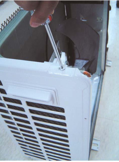
 Loosen one of the right screw and detach the Terminal Cover.")
1 4. Disassembly and Reassembly Stop operation of the air conditioner and remove the power cord before repairing the unit. 4-1 Indoor Unit MH FPEA /MH VP2-1 Front Panel 1) Stop the air conditioner operation and shut off the main power. 2) Detach tape of Front Panel upper. 3) Slide the lower Front Grille down, then disassemble it by pulling it forwards. 4) Open the upper Front Grille by pulling right and left sides of the Grille. 5) Take the left and right Filter out. 6) Loosen one of the right screw and detach the Terminal Cover. 7) Detach the thermistor from the Front Grille. 8) Loosen 5 fixing screws of Front Grille. 9) Pull the lower left and right of discharge softly for the outside cover to be pulled out. 4-1


 2) Detach the outdoor unit connection wire from the Terminal")
2 10) At first, press the left and center hook of the back side of the Panel Grille with the thumb to remove the hook. And press the right of the upper side of the Panel Grille with the fingers. And then disassemble the Panel Grille. 2 Electrical Parts (Main PCB) 1) Take all the connector of PCB upper side out.(including Power Cord) 2) Detach the outdoor unit connection wire from the Terminal Block. 3) If pulling the main PCB up, it will be taken out. 3 Tray Drain 1) Pull Tray Drain out from the Back Body. 4-2

 Detach the Holder Pipe at the rear side.")
 Detach the Heat Exchanger from the")
 Loosen 2 fixing")
 Loosen the fixing screw of Fan Motor.")
3 4 Heat Exchanger 1) Loosen 2 fixing earth screws of right side. 2) Detach the Connection Pipe. 3) Detach the Holder Pipe at the rear side. 4) Loosen 3 fixing screws of right and left side. 5) Detach the Heat Exchanger from the indoor unit. 5 Fan Motor & Cross Fan 1) Loosen 2 fixing screws and detach the Motor Holder. 2) Loosen the fixing screw of Fan Motor. (with a M3 wrench) 3) Detach the Fan Motor from the Fan. 4) Detach the Fan from the left Holder Bearing. 4-3

 Detach the Front Grille after pushing")
 Loosen 1 of the right screw and detach")
 Loosen 1 of the right screw and detach")
4 4-1-2 MH FWEA/MH VW2-1 Panel Front 1) Stop the air conditioner operation and shut off the main power. 2) Detach the Front Grille after pushing out it. 3) Loosen 1 of the right screw and detach the Ass'y display. 4) Loosen 1 of the right screw and detach the Terminal Cover. 5) Detach the cover PCB-DVM and thermistor from the Panel Front. 4-4


5 6) Loosen 5 fixing screws of Panel Front. 7) Unlock 2 hooks to fix Panel Front and Tray Drain. 8) Unlock 2 hooks to fix Panel Front and Back Body. 2 Tray Drain 1) Detach the connected wire of Stepping Motor. 2) Pull Tray Drain out from the Back Body. 3 Heat Exchanger 1) Loosen 1 fixing earth screw of right side. 4-5
 Detach the Holder Pipe at")
 Loosen 3 fixing screws of")
 Loosen 1 fixing screw of")
 Detach the Heat Exchanger")
6 2) Detach the Room Sensor. 3) Detach the Holder Pipe at the rear side of the unit. 4) Loosen 3 fixing screws of left Holder Evap. 5) Loosen 1 fixing screw of right Holder Motor. 6) Detach the Heat Exchanger from the indoor unit. 4-6
 Take all the connector of PCB upper side out.")
 Pull the PCB up to detach.")
 Loosen 1 fixing screw of Fan Motor.")
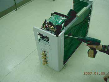
7 4 Electrical Parts (Main PCB) 1) Loosen 4 fixing screws of right Holder control. 2) Take all the connector of PCB upper side out.(including Power Cord) 3) Detach the outdoor unit connection wire from the Terminal Block. 4) Pull the PCB up to detach. 5 Fan Motor & Cross Fan 1) Loosen 2 fixing screws and detach the Motor Holder. 2) Loosen 1 fixing screw of Fan Motor. 3) Detach the Fan Motor from the Fan. 4) Detach the Fan from the left Holder Bearing. 4-7

 Please open the Front Grille.")


8 4-1-3 MH FVEA/MH VV1-1 Panel Front 1) Stop the driving of air conditioner and shut off Main Power supply. 2) Please open the Front Grille. 3) Please detach link Grilles from Main Frame. 4) To detach Front Grille from Main Frame, please catches finger stop. 5) Please loosen clamping screw and detach the Terminal Cover. 4-8


 Loosen screws 3EA at the")
 Loosen the")
 Please separate Linked")
9 6) Please take out Filter to downward. 7) Please detach the cover screw 3EA from the bottom of the Panel Front. 8) Loosen screws 3EA at the bottom of Panel Front and 2EA at the front of the Panel Front. 9) Loosen the screw of the Ass y Display. 10) Please separate Linked connector from the Ass y Display. 4-9

 Unlock 2 hooks between Panel")
 Please detach")
 Please pull Tray Drain and")
10 11) Unlock 2 hooks between Panel Front and Try Drain to separate Panel Front. 12) Unlock 2 hooks between Panel Front and Back Body. 2 Tray Drain 1) Please detach stepping motor wire. 2) Please pull Tray Drain and separate from Back Body. 3 Evap 1) Loosen the ground wire screw. 4-10
 Detach the Holder Pipe.")


11 2) Detach the Temperature Sensor. 3) Detach the Holder Pipe. 4) Loosen 3 EA screws, left of Holder Evap. 5) Loosen 1EA screw,right of Holder Motor. 6) Detach the Heat Exchanger from Indoor Unit. 4-11
 Detach Link wires of indoor, Outdoor Unit and Fan Motor.")
 Loosen 2EA screws of Holder Motor and Detach the")
12 4 Main PCB 1) Loosen 4EA screws of Holder. 2) Detach Link wires of indoor, Outdoor Unit and Fan Motor. 3) Detach Ass y Control from Indoor Unit. 5 Fan Motor & Cross Fan 1) Loosen 2EA screws of Holder Motor and Detach the holder. 2) Loosen a screw and detach the Cross Fan. 3) Detach the Holder Bearing and Motor. 4-12


 Detach the Front Grille.")
13 4-1-4 MH FKEA 1 Front Grille & Filter 1) Open the Front-Grille by pushing the tabs on the Grille. You must give attention when disassembling the Front-Grille and must check the safety clips have been installed. If you don t ensure them, the Front Grille will drop suddenly and you will be hurt. 2) Detach the Front Grille. (1) Remove the safety clips. (2) Open the Front Grille about 45 and pull it forward. 3) Pull out the Air-Filter. 4-13


 Detach the")

14 2 Front Panel 1) Loosen 6 fixing screws holding the panel as shown picture. 2) Detach the Front-Panel pressing the 2 hooks on the both sides of the indoor unit. 4-14


15 3 Drain Panel 1) Loosen 4 fixing screws for Ass'y Drain Panel around as shown in pictures. 2) Detach Ass'y Drain Panel as shown in Pictures. 4-15


16 4 Control In 1) Detach the Control Cover after disassembling 2 screws as shown in pictures. 2) Detach the wire connection part of the Ass'y Main PCB as shown in picture. 4-16


17 3) Loosen 2 fixing screws of Case Control as shown in pictures. 4) Loosen the fixing screw. 5) Detach the Ass'y Case Control part pulling up. 4-17


18 6) Loosen the fixing screw and detach earth cable. 7) Loosen the fixing screw and detach Terminal Cover as shown in pictures. 8) Loosen 2 fixing screws as shown in pictures. 4-18


 Detach Base")
19 9) Loosen 2 fixing indicating screws of earth cable and the fixing screw of Base Terminal. 10) Detach Base Terminal as shown in picture. 4-19


 Loosen 3")


20 5 Drain Panel Sub 1) Detach Ass'y Drain Panel Sub after loosen 2 fixing screws both side of it. 6 Evap 1) Loosen 3 fixing screws of Ass'y Evap around. 2) Loosen 2 fixing screws as shown in picture and detach Ass'y Cabinet-Side LF B. 4-20

 Loosen 3 fixing")

 Loosen 4")

21 3) Detach Ass'y Evap pulling up from the indoor unit as shown in picture. 7 Cross Fan 1) Loosen 3 fixing screws of cover Fan Motor and detach cover Fan Motor. 2) Detach Ass'y Cross Fan as shown in picture. 8 Drain Pump 1) Loosen 4 fixing screws as shown in picture. 2) Detach Drain Hose and detach Ass'y Drain Pump as shown in pictures. 4-21
 Push")

 Open the Front Grille at")

 Filter Disassembly (1) Draw")
22 4-1-5 MH FMEA 1 Front Grille -Dust-Collecting Filter 1) Push the tap on the Front Grille to open it. 2) Disassembly of Front Grille. (1) Open the Front Grille at about 45 degrees and draw it forward. (2) Disassemble the Safety Clip. 3) Filter Disassembly (1) Draw the Dust-Collecting Filter forward. (2) Disassemble the Filter. 4-22
 Loosen the bolt of the")


 Disassemble the 2 cables")

23 4) Loosen the 4 bolts slowly. 5) Loosen the bolt of the front net to disassemble the safety net. 6) Loosen the 3 bolts to uncover the Component Electric Box cover. 7) Disassemble the 2 cables between the indoor unit and the Panel. Stepping Motor Connector Receiving & Display Unit Connector Option 4-23


 Disconnect all the Indoor")


24 8) Hold on the 2 hooks on both sides of the indoor unit and disassemble the Front Panel. 9) Take away the disassembled Panel out of the main body. 2 Electronic Part - Indoor & Outdoor Connecting Cable 1) Disconnect all the Indoor and Outdoor Cables Connected to the Terminal Board. 3 Fan & Motor 1) Disassemble the Fan Motor wire connector, thermistor wire connector, and Drain Pump wire connector. 2) Disassemble the wire connector in the Capacitor. 4-24


25 3) Disassemble the ground wire. 4) Disassemble the Float Switch wire connected to the Terminal Port.(F1, F2) 5) Loosen the 4 bolts in the mark. 6) Disassemble the Base Control from the main body. 7) Loosen the 4 bolts in the mark. 4-25


 Lift")

 Loosen the")
26 8) Disassemble the Drain Cushion from the main body. 9) Loosen the nut. 10) Lift the Fan to disassemble from the Motor. 11) Loosen the bolt. 4-26


27 12) Loosen 4 bolts to disassemble the Motor. 4 Pump 1) Loosen the 2 bolts of the Drain Pump. 2) Disassemble the Hose from the Drain Pump. 3) Disassemble the Pump from the main body Bracket. 4-27


 1)")

 Loosen the bolt fixing the PCB")
28 5 Heat Exchanger 1) Disassemble the cover pipe beside the main body. 2) Disassemble the 1 fixing Bracket of the Heat Exchanger to disassemble it from the main body. 6 Front Panel (PCB Panel) 1) Loosen 3 bolts fixing the Control C and then lift it up. 2) Disassemble the Clamp. 3) Loosen the bolt fixing the PCB to disassemble the PCB. 4-28


29 4) Disassemble the PCB Wire from the PCB. 5) Disassemble the Bottom PCB and PCB. 4-29
 1) Loosen 3 bolts")


 Disassemble the Motor")

30 7 Front Panel (Stepping Motor) 1) Loosen 3 bolts fixing the Control Panel and then lift it up. 2) Disassemble the Stepping Motor and disassemble the link. 3) Disassemble the Motor from the Bracket and disassemble the Motor Wire Connected. 4-30

 Turn the Plate Handle by hand when removing the Filter-Pre.")

.")
31 4-1-6 MH FDEA (Silhouette Duct) 1 Filter-Pre 1) Disassemble screws of indication part and then assemble the direction of 2 Plate-Handle places by use of screw as shown in 2). 2) Turn the Plate Handle by hand when removing the Filter-Pre. 3) When pulling the Filter-Pre handle, the Filter-Pre can be assembled. Be sure to remove the cushion on the marked part after initial installation. (It cause the damage of noise). 2 Blower & Duct 1) After disassembling places indicating screws, detach Ass'y Cover Bottom. 4-31


 Detach the Ass'y")
32 2) Disassemble indicating screws. 3) Detach the sensor holder from the Ass'y Fan case. 4) Detach from Ass'y Control in the capacitor connection wire between the Motor-Fan in and Housing Connector. 5) Detach the Ass'y Blower and Duct from the set. 4-32

 Detach the Motor-Fan in and")
 Hold the Ass'y Control In by")

33 3 Control In 1) After disassembling indicating screw, detach the Cover-Control. 2) Detach the Motor-Fan in and Sensor Connector connected to PCB. 3) Hold the Ass'y Control In by hand to lift up a little and then release the status of hanging on the hanging slot. 4-33


 Disassemble indicating screws.")


34 4 Drain Pan 1) Disassemble indicating screws to detach Ass'y Drain Pan. (screws each at left and right side) 5 Evap Work is possible when disassembling the Ass'y Drain Pan. 1) Disassemble indicating screws. (each at left and right side) 2) Disassemble indicating screws. 3) Disassemble indicating screws. It is possible at the status of No.3 Ass'y Control In disassembly at the time. 4-34


 Separate (each at left")

35 4) After disassembling indicating screws. 5) Pull the Cabinet-Side LF, RH by hand to disassemble. 6) Separate indicating screws. (each at left and right side) 7) Detach it from the set if the Ass'y-Evap pull up. 4-35
 Disassemble indicating screws.")
 After connecting canvas to the disassembled Ass'y")
36 6 Holder Outlet When connecting canvas to the discharge side. 1) Disassemble indicating screws. (each at left and right side) 2) Disassemble indicating screws. (each at upper and lower side) After connecting canvas to the disassembled Ass'y Holder Outlet 2), attach the Ass'y Holder Outlet to the set in the reverse order. 4-36
 Disassemble the Cabinet")
 Disassemble 2")


 Disassemble")
37 4-1-7 MH FEEA (Slim Duct1) 1 Motor & Blower 1) Disassemble the Cabinet Top Motor. Unscrew 8 screws 2) Disassemble 2 Cover Blower Uppers. After unscrewing 2 screws Disassemble the Cover Blower Upper with pushing its hook. 3) Disassemble the Cover Control. Unscrew 2 screws 4) Disassemble Motor Wires connected to the inside of PCB and connected to the Capacitor. 4-37


38 5) Disassemble the Motor earth wire connected to the Partition. Unscrew a screw 6) Disassemble the band Motor for fixing the Motor. Unscrew 2 screws 7) After disassembling the Motor and Blower for the set, disassemble the Blower by use of 3mm wrench. 2 Drain Pan 1) Disassemble the Cabinet Top Evap. Unscrew 11 screws 4-38


 and the")
 Disassemble the Cover Pipe that fixes the")
 Disassemble the refrigerant")
39 2) Disassemble the Bracket Outlet Sub that fixes the Drain Pan equipped on the front of the set. Unscrew 6 screws 3) Disassemble the Drain Cushion from the set. 3 Evaporator The Evaporator should be disassembled after disassembling the Cover Control 1-3) and the Drain Pan 2-1), 2-2), 2-3). 1) Disassemble the Cover Pipe that fixes the high/low pressure Pipe. Unscrew 2 screws 2) Disassemble the refrigerant temperature sensor, Inlet air temperature sensor, and EEV wire that connected to the inside of PCB. 4-39

 Disassemble the")

.")

40 3) Disassemble the Support Evap. LF that fixes the Evaporator. Unscrew 2 screws 4) Disassemble the Support Evap RH. Unscrew 2 screws 5) Disassemble the Evaporator form the set. 4 Control In The Control In should be disassembled after disassembling the Cover Control 1-3). 1) Disassemble all Control Wires connected to the inside of PCB. 2) In case of disassembling the PCB separately, disassemble the PCB from the case with pushing the hook after unscrewing the screw. Unscrew 1 screw 4-40


.")

41 3) In case of disassembling the Capacitor separately, disassemble the Capacitor from the Case. 4) In case of disassembling the Case Control, disassemble the Case Control from the set after unscrewing the screw connected to the direction of Blower. Disassemble if after disassembling the Cabinet Top Motor 1-1). 5) In case of disassembling the Trans Power, unscrew the screw fixing on the Case. Disassemble if after disassembling the case PCB 4-4). 5 Bracket Outlet 1) Disassemble the Bracket Outlet assembled on the Cabinet. Unscrew 10 screws 4-41
 1 Filter 1)")


42 4-1-8 MH FEEA (Slim Duct2) 1 Filter 1) Pull out the Filter as picture 1 or picture 2. 2) If it is necessary, after disassembling 8 indicating screws, detach the Bracket Filter. 4-42


 After disassembling 3 indicating")

43 3) If the Cabinet-Top Motor is assembled on the side of the set, the procedure of disassembling the Filter is just as the above. 2 Blower & Motor 1) After disassembling 13 indicating screws, detach Ass'y Cabinet-Top Motor. 2) After disassembling 3 indicating screws, detach Ass'y Case Blower Upper. - Press the pothook of the Case Blower and detach Ass'y Case Blower Upper. 4-43

 Detach the Motor Wire")


 After disassembling 2")
44 3) After disassembling 2 indicating screws, detach the Cover Control. 4) Detach the Motor Wire Connected to PCB and Capacitor. 5) After disassembling the indicating screws, detach the wire connected to the Partition. 6) After disassembling 2 indicating screws, detach the Ass'y Band Motor. 4-44


 After disassembling 6 indicating")
45 7) After disassembling the Motor and Blowers, detach the Blowers from the axis of the Motor by 3mm inner hexagon spanner. 4 Drain Pan 1) After disassembling 15 indicating screws, detach Ass'y Cabinet-Top Evap. 2) After disassembling 6 indicating screws, detach the Bracket Outlet. 3) Detach the Drain Pan. 4-45

 After disassembling 2 indicating")
 Detach the Sensor from the")
 3) After")

46 4 Evaporator After finished the procedures above, detach the Evaporator. 1) After disassembling 2 indicating screws, detach Ass'y Cover Pipe. 2) Detach the Sensor from the Control Box.(including 2 Sensors) 3) After disassembling 2 indicating screws, detach Ass'y Support Evap LF. 4) After disassembling 2 indicating screws, detach Ass'y Support Evap RH. 4-46

 Detach all the wires connected to the PCB.")


47 5) Detach the Evaporator from the set. 5 Control In Detach the parts of Control In after disassembling the Cover Control. 1) Detach all the wires connected to the PCB. 2) If only the disassembly of PCB required, press the Pothook and detach the PCB from the set. 3) If only the disassembly of Capacitor is required, detach it from the set. 4) If only the disassembly of Case Control is required, detach it from the set after disassembling 2 indicating screws. 4-47


48 5) Detach the Transformer after disassembling 2 indicating screws. Work is possible after disassembling the Case PCB. 6 Ass'y Bracket Outlet 1) After disassembling 16 indicating screws, detach Ass'y Bracket Outlet. 4-48


49 4-2 Outdoor Unit Take care of the electrical shock by contact on the charging parts before the discharge after power off. (If takes approximately 2 minutes to discharge.) MH040FXEA2A 4-49
50 4-50

 Detach several connectors from")


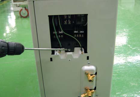
51 2 Ass y Control Out 1) Detach the Motor Wire from the PCB of Ass'y Control Out. 2) Detach several connectors from the PCB of Ass'y Control Out. 3) Detach 2 Connect Wires from Reactor. 4) Loosen 1 screw(ccw)fixed to assemble Ass'y Control Out with Partition. (Use +Screw Driver.) 4-51
52 4-52
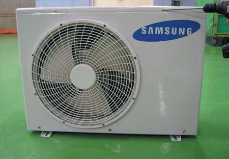
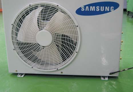
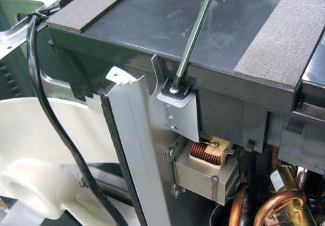
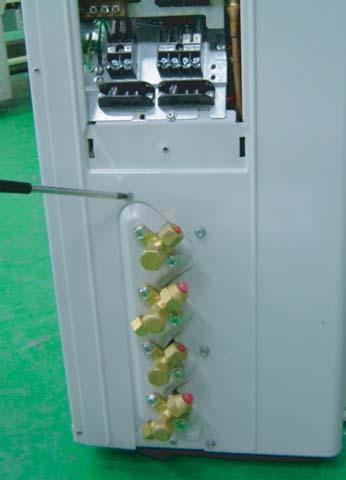
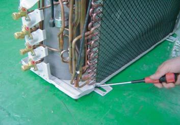
53 4-2-2 MH040FXEA2/MH052FXEA2/MH14VP2X/MH16VP2X/MH18VP2X/MH19VP2X/MH14VW2X/MH16VW2X/ MH18VW2X/MH19VW2X/MH052FXEA2A/MH060FXEA3A/MH18VV1X/MH19VV1X 1 Common Work & Control Out 1) Loosen the fixing screw and detach the Cover-Control. 2) Detach the Cable-Connector Wire from the Terminal-Block. 3) Loosen the fixing screw of the Ass'y Control Out. 4) Loosen 8 fixing screws and detach the Cabinet Upper. 5) Loosen 2 fixing screws, 5 bolts and detach the Front Cabinet. 6) Loosen 2 fixing screws and pull up the Control Box. 4-53


 Loosen 4 fixing bolts")
 Loosen 2 fixing bolts")
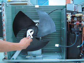
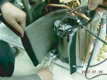
54 7) Loosen 9 fixing screws and detach the Cabinet Side. 8) Detach the Terminal and detach the Compressor Lead Wire. 2 Fan & Motor 1) Loosen the fixing nut and detach the Fan. 2) Loosen 4 fixing bolts and detach the Motor. 3) Loosen 2 fixing bolts and detach the Bracket Motor. 4-54
 Disassemble the Inlet and Outlet Pipe by welding.")
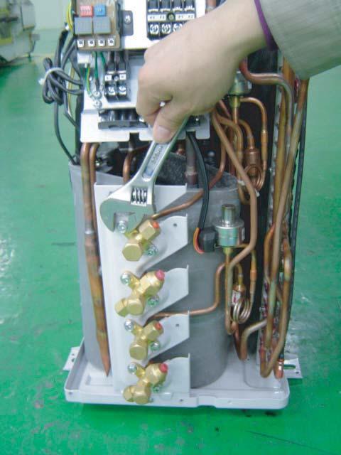
 Detach the Heat Exchanger. 5) Loosen 3 nuts of the Compressor.")
55 3 Heat Exchanger & Compressor 1) Release the refrigerant at first. 2) Disassemble the Inlet and Outlet Pipe by welding. 3) Loosen the fixing screws of the Heat Exchanger. 4) Detach the Heat Exchanger. 5) Loosen 3 nuts of the Compressor. 6) Detach the Compressor. 4-55
")
 Detach the Cable-Connector Wire from the")
 Loosen 2 fixing screws of the Ass'y Control Out.")
 Loosen 6 fixing screws, 7 bolts and detach the")
56 4-2-3 MH068FXEA4/MH080FXEA4/MH30VP2X/MH30VW2X MH070FXEA4A/MH080FXEA4A 1 Common Work & Control Out 1) Loosen the fixing screw and detach the Cover-Control. 2) Detach the Cable-Connector Wire from the Terminal-Block. 3) Loosen 2 fixing screws of the Ass'y Control Out. 4) Loosen 8 fixing screws and detach the Cabinet Upper. 5) Loosen 6 fixing screws, 7 bolts and detach the Cabinet Front. 6) Loosen 4 fixing screw and pull up the Control Box. 4-56


 Loosen 4 fixing bolts and")
 Loosen 3 fixing bolts and")
57 7) Loosen 12 fixing screws and detach the Cabinet Side. 8) Detach the Terminal Cover and detach the comp lead wire. 2 Fan & Motor 1) Loosen the fixing nut and detach the Fan. 2) Loosen 4 fixing bolts and detach the Motor. 3) Loosen 3 fixing bolts and detach the Bracket Motor. 4-57
 Disassemble the Inlet and Outlet Pipe by welding.")
 Detach the Heat Exchanger. 5) Loosen 3 nuts of the Compressor.")
58 3 Heat Exchanger & Compressor 1) Release the refrigerant at first. 2) Disassemble the Inlet and Outlet Pipe by welding. 3) Loosen the fixing screw of the Heat Exchanger. 4) Detach the Heat Exchanger. 5) Loosen 3 nuts of the Compressor. 6) Detach the Compressor. 4-58
59 MEMO 4-59
SERVICE Manual FREE JOINT MULTI AIR CONDITIONER
 FREE JOINT MULTI AIR CONDITIONER INDOOR UNIT MH020FPEA MH023FPEA MH026FPEA MH035FPEA MH052FPEA MH8VP2-09 MH9VP2-07 MH9VP2-2 MH026FKEA MH035FKEA MH052FDEA OUTDOOR UNIT MH8VP2X MH9VP2X MH052FXEA2 MH068FXEA4
SERVICE Manual SYSTEM AIR CONDITIONER INDOOR UNIT GH052EAM GH070EAM OUTDOOR UNIT UH052EAMT UH070EAMT. 1. Product Specifications
 SYSTEM AIR CONDITIONER INDOOR UNIT GH052EAM GH070EAM OUTDOOR UNIT UH052EAMT UH070EAMT SERVICE Manual SYSTEM AIR CONDITIONER CONTENTS 1. Product Specifications 2. Disassembly and Reassembly 3. Set Up the
RC-54CA RO-50CA RC-54HA RO-50HA. SPLIT TYPE AIR CONDITIONER CASSETTE TYPE (50Hz) Indoor unit Outdoor unit
 Indoor unit Outdoor unit") SPLIT TYPE AIR CONDITIONER CASSETTE TYPE (50Hz) Indoor unit Outdoor unit RCW-54CB RO-50CA RC-54CA RO-50CA RC-54HA RO-50HA CONTENTS SPECIFICATIONS OUTLINE AND DIMENTIONS CIRCUIT DIAGRAM REFRIGERANT SYSTEM
SPLIT TYPE AIR CONDITIONER CASSETTE TYPE (50Hz) Indoor unit Outdoor unit RCW-54CB RO-50CA RC-54CA RO-50CA RC-54HA RO-50HA CONTENTS SPECIFICATIONS OUTLINE AND DIMENTIONS CIRCUIT DIAGRAM REFRIGERANT SYSTEM
SERVICE MANUAL FOR MODEL RM-10
 SERVICE MANUAL FOR MODEL RM-10 REQUIRED TOOLS CORDLESS DRILL COPPER CUTTING TUBE 1/2 OPEN WRENCH SOLDERING IRON SCREWDRIVER SET WITH 9/32 SOCKET VISE GRIP PIERCING VALVE PRECISION FLAT BLADE SLOTTED SCREWDRIVER
SERVICE MANUAL FOR MODEL RM-49
 SERVICE MANUAL FOR MODEL RM-49 REQUIRED TOOLS CORDLESS DRILL DRIVE CUTTING TUBING OPEN WRENCH OF 1/2 RATCHET WITH SOCKET OF 7/16 SCREWDRIVER SET WITH SOCKET OF 9/32 VISE GRIP PIERCING VALVE WATCHER SLOTTED
Model name: AJ009JNNDCH AJ012JNNDCH AJ018JNNDCH AJ007JNADCH AJ009JNADCH AJ012JNADCH
 Model name: AJ009JNNDCH AJ012JNNDCH AJ018JNNDCH AJ007JNADCH AJ009JNADCH AJ012JNADCH MULTI AIR CONDITIONER INDOOR UNIT AJ018JNADCH AJ024JNADCH AJ009JNLDCH AJ012JNLDCH AJ018JNLDCH OUTDOOR UNIT AJ020JCJ2CH
SERVICE MANUAL FOR MODEL RM-26
 SERVICE MANUAL FOR MODEL RM-26 REQUIRED TOOLS CORDLESS DRILL DRIVE CUTTING TUBING OPEN WRENCH OF 1/2 RATCHET WITH SOCKET OF 7/16 SCREWDRIVER SET WITH SOCKET OF 9/32 VISE GRIP PIERCING VALVE WATCHER SLOTTED
SERVICE Manual CASSETTE TYPE AIR CONDITIONER INDOOR UNIT KH026EAM KH035EAM OUTDOOR UNIT UH026EAM UH035EAM. 1. Product Specifications
 CASSETTE TYPE AIR CONDITIONER INDOOR UNIT KH026EAM KH035EAM OUTDOOR UNIT UH026EAM UH035EAM SERVICE Manual AIR CONDITIONER CONTENTS 1. Product Specifications 2. Disassembly and Reassembly 3. Block Diagrams
AIR CONDITIONER OUTDOOR UNIT INDOOR UNIT. 1. Precautions
 MULTI AIR CONDITIONER INDOOR UNIT AJ009JNNDCH/AA AJ012JNNDCH/AA AJ018JNNDCH/AA AJ007JNADCH/AA AJ009JNADCH/AA AJ012JNADCH/AA AJ018JNADCH/AA AJ024JNADCH/AA AJ009JNLDCH/AA AJ012JNLDCH/AA AJ018JNLDCH/AA AJ009NBNDCH/AA
CASSETTE type INVERTER MULTI AIR CONDITIONER. Models AUY12LBAB AUY14LBAB AOY18LMAK2
 INVERTER MULTI AIR CONDITIONER CASSETTE type Models Indoor unit AUY12LBAB AUY14LBAB Outdoor unit AOY18LMAK2 CONTENTS SPECIFICATIONS..................... 1 OUTLINE AND DIMENSIONS........... 2 REFRIGERANT
Service Parts for models UF424 and UN324
 Service Parts for models UF and UN This is the illustrated parts list for Scotsman ice maker models UF and UF. They were manufactured as either air or water cooled models, plus the air cooled models were
ALLDATA Online Scion xb L4-1.5L (1NZ-FE) - Service and Repair. Service and Repair. Air Conditioning Blower Assy Part 1
 - Service and Repair. Service and Repair. Air Conditioning Blower Assy Part 1") Page 1 of 16 Service and Repair Air Conditioning Blower Assy Part 1 Air Conditioning Blower Assy Part 2 Page 2 of 16 OVERHAUL 1. DISCHARGE REFRIGERANT FROM REFRIGERATION SYSTEM SST 07110-58060 (07117-58080,
Page 1 of 16 Service and Repair Air Conditioning Blower Assy Part 1 Air Conditioning Blower Assy Part 2 Page 2 of 16 OVERHAUL 1. DISCHARGE REFRIGERANT FROM REFRIGERATION SYSTEM SST 07110-58060 (07117-58080,
3. DISCONNECT AIR CONDITIONING TUBE ASSY SST HINT: Disconnect in the same way as the cooler refrigerant suction hose No.1.
 5517 550JD04 OVERHAUL COMPONENT: See page 5515 1. DISCHARGE REFRIGERANT FROM REFRIGERATION SYSTEM (See page 5511) SST 0711058060 (0711758080, 0711758090, 0711778050, 0711788060, 0711788070, 0711788080)
1 of 18 6/26/2014 7:22 PM
 1 of 18 6/26/2014 7:22 PM Air Conditioning Blower Assy Part 1 2 of 18 6/26/2014 7:22 PM Air Conditioning Blower Assy Part 2 OVERHAUL 1. DISCHARGE REFRIGERANT FROM REFRIGERATION SYSTEM SST 07110-58060 (07117-58080,
WALL MOUNTED type SPLIT TYPE ROOM AIR CONDITIONER CONTENTS. Models
 SPLIT TYPE ROOM AIR CONDITIONER WALL MOUNTED type Models Indoor unit ASY9USCCW ASY9USCCW ASY12USCCW Outdoor unit AOY9USCC AOY9UFCC AOY12USCC CONTENTS SPECIFICATIONS................................... 1
CASSETTE type INVERTER MULTI AIR CONDITIONER
 INVERTER MULTI AIR CONDITIONER CASSETTE type Models Indoor unit AUY12LBAB AUY14LBAB Outdoor unit AOY18LMAK2 CONTENTS SPECIFICATIONS..................... 1 OUTLINE AND DIMENSIONS........... 2 REFRIGERANT
DUCT type. Большая библиотека технической документации каталоги, инструкции, сервисные мануалы, схемы.
 SPLIT TYPE AIR CONDITIONER (50Hz) DUCT type Models Indoor unit Outdoor unit RD-25CA RD-25HA RD-30CA RD-30HA RO-25CA RO-25HA RO-30CA RO-30HA C O N T E N T S SPECIFICATIONS.............................................
AIR CONDITIONER. Model : 1. Precautions. 2. Product Specifications. 3. Disassembly and Reassembly. 4. Troubleshooting. 5.
 SYSTEM AIR CONDITIONER Model : INDOOR UNIT AC012MNADCH/AA AC018MNADCH/AA AC024MNADCH/AA AC030MNTDCH/AA AC036MNTDCH/AA OUTDOOR UNIT AC012KXADCH/AA AC018JXADCH/AA AC024JXADCH/AA AC030JXADCH/AA AC036JXADCH/AA
Installation Guide BUILT-IN SXS REFRIGERATOR UPSXB2627**
 Installation Guide BUILT-IN SXS REFRIGERATOR UPSXB2627** www.thesignaturekitchen.com 2 Contents 1. Precaution before installation... 3 2. Product and Cutout dimension... 4 3. Precaution when moving the
6868 Ardmore Street Houston, Texas Toll Free Phone Fax
 P-09 P-09 P-09A COMPONENT PART NO. COMPONENT PART NO. BASE PAN 67904000 AIR OUTTAKE 67809008 OUTDOOR CENTRIFUGAL FAN 67809032 TURNING WHEEL (CASTER) 67904001 (4) ERECT LOUVER ASSY 67809006 (5) OUTDOOR
Air Conditioner. user installation & manual manual. imagine the possibilities
 ARFSSSBWK Series ARFSSSCUR AJ JNADCH Series Air Conditioner user installation & manual manual This manual is made with 100% recycled paper. imagine the possibilities Thank you for purchasing this Samsung
Si REMOVAL PROCEDURE. 4.0/5.0/5.2/5.8/6.8/7.5 kw Class. Outdoor Unit Inverter Multi Type
 Si121174 REMOVAL PROCEDURE S E R V I C E M A N U A L 4.0/5.0/5.2/5.8/6.8/7.5 kw Class Outdoor Unit Inverter Multi Type Service Manual Removal Procedure Outdoor Unit Applicable Models Cooling Only 3MKS50E3V1B
RAS-10JKVP-E RAS-10JAVP-E RAS-13JKVP-E RAS-13JAVP-E
 FILE NO. A0-05 SPLIT TYPE RAS-0JKVP-E RAS-0JAVP-E RAS-3JKVP-E RAS-3JAVP-E PRINTED IN JAPAN, Jun.,003 ToMo . EXPLODED VIEWS AND PARTS LIST -. Indoor Unit () 0 0 6 35 5 4 0 5 33 7 08 6 07 9 3 0 3 8 30 39
REASSEMBLY; 2007 MY CAMRY [01...
 REASSEMBLY; 2007 MY CAMRY [01... Last Modified: 2 7 2013 6.4 A Doc ID: RM000001HLY001X Model Year: 2007 Model: Camry Prod Date Range: [01/2006 ] Title: AIR CONDITIONING: AIR CONDITIONING UNIT: REASSEMBLY;
HID312, HID525 and HID540 Service Parts
 This is the illustrated parts list for Scotsman ice maker-dispenser models HID, HID and HID0. They were manufactured in voltages and there is also a separate wall mount model. Please confirm the complete
CASSETTE type (50Hz) SPLIT TYPE AIR CONDITIONER. Models Indoor unit Outdoor unit
 SPLIT TYPE AIR CONDITIONER. Models Indoor unit Outdoor unit") SPLIT TYPE AIR CONDITIONER CASSETTE type (50Hz) Models Indoor unit Outdoor unit RCW-12HA RO-12HB C O N T E N T S SPECIFICATIONS........................................ 1 OUTLINE AND DIMENSIONS..............................
SPLIT TYPE AIR CONDITIONER CASSETTE type (50Hz) Models Indoor unit Outdoor unit RCW-12HA RO-12HB C O N T E N T S SPECIFICATIONS........................................ 1 OUTLINE AND DIMENSIONS..............................
SIDE BY SIDE REFRIGERATOR MODELS: WRS325SDHW00 (White) WRS325SDHB00 (Black) WRS325SDHV00 (Black Stainless) WRS325SDHZ00 (Stainless Steel)
 WRS325SDHB00 (Black) WRS325SDHV00 (Black Stainless) WRS325SDHZ00 (Stainless Steel)") SIDE BY SIDE REFRIGERATOR MODELS: WRS325SDHW00 (White) WRS325SDHB00 (Black) WRS325SDHV00 (Black Stainless) WRS325SDHZ00 (Stainless Steel) 03/21/2018 2018 Whirlpool Corporation Part No. W11157383 Rev. B
SIDE BY SIDE REFRIGERATOR MODELS: WRS325SDHW00 (White) WRS325SDHB00 (Black) WRS325SDHV00 (Black Stainless) WRS325SDHZ00 (Stainless Steel) 03/21/2018 2018 Whirlpool Corporation Part No. W11157383 Rev. B
INSTALLATION MANUAL Duct Type Series MH FECA
 INSTALLATION MANUAL Duct Type Series MH FECA ENGLISH FRANÇAIS ESPAÑOL Free Joint Multi Air Conditioner (Cooling and Heating) E S F DB98-960A() Safety Precautions The following safety precautions must be
427 DOOR VIEW PARTS LIST
 Parts Lists & Exploded Views 7 DOOR VIEW PARTS LIST 00 Series 1. 171 Glass Door Assy- RH (Does Not Include Hinges or Handle) 17 Glass Door Assy- LH (Does Not Include Hinges or Handle) 181 Door Assy, (High
TCB-DP22CUL. Drain Pump Kit. Model name : AIR CONDITIONER (SPLIT TYPE) Installation Manual. Installation Manual 2 Air Conditioner (Split type) English
 Installation Manual. Installation Manual 2 Air Conditioner (Split type) English") AIR CONDITIONER (SPLIT TYPE) Model name : TCB-DP22CUL 2 Air Conditioner (Split type) English Manuel D installation Climatiseur (Type split) 12 Français Please read this carefully before installing the
AIR CONDITIONER (SPLIT TYPE) Model name : TCB-DP22CUL 2 Air Conditioner (Split type) English Manuel D installation Climatiseur (Type split) 12 Français Please read this carefully before installing the
Si REMOVAL PROCEDURE. 2.5/3.2/3.5 kw Class. Outdoor Unit Inverter Pair Type
 Si001158 REMOVAL PROCEDURE S E R V I C E M A N U A L 2.5/3.2/3.5 kw Class Outdoor Unit Inverter Pair Type Service Manual Removal Procedure Outdoor Unit Applicable Models Heat Pump RXS225KC RXS232KC RXS225KCG
P MODEL AIR CONDITIONER
 CONSUMER SERVICES TECHNICAL EDUCATION GROUP PRESENTS R-94 P MODEL AIR CONDITIONER JOB AID Part No. 8178039 FORWARD This Whirlpool Job Aid, P Model Air Conditioner (Part No. 8178039), provides the technician
CABINET PARTS For Model: KSF26C6XYY00 (Monochromatic Stainless)
") CABINET PARTS REFRIGERATOR 11 11 Litho In U.S.A. (wam) (eeb) 1 Part No. Rev. B CABINET PARTS 1 Literature Parts W10368322 Use & Care Guide W10287673 Service & Wiring Sheet W10403232 Energy Label 2 2150304
CABINET PARTS REFRIGERATOR 11 11 Litho In U.S.A. (wam) (eeb) 1 Part No. Rev. B CABINET PARTS 1 Literature Parts W10368322 Use & Care Guide W10287673 Service & Wiring Sheet W10403232 Energy Label 2 2150304
INSTALLATION MANUAL. Split-type Air Conditioner (Cooling and Heating) Outdoor Unit UQB09JJWC UQB12JJWC. Indoor Unit AQB09JJWC AQB12JJWC
 Outdoor Unit UQB09JJWC UQB12JJWC. Indoor Unit AQB09JJWC AQB12JJWC") AQB09JJ6WC_IM_E_2585 2006.4.17 4:26 PM Page 17 INSTALLATION MANUAL Indoor Unit AQB09JJWC AQB12JJWC Outdoor Unit UQB09JJWC UQB12JJWC ENGLISH FRANÇAIS ESPAÑOL Split-type Air Conditioner (Cooling and Heating)
AQB09JJ6WC_IM_E_2585 2006.4.17 4:26 PM Page 17 INSTALLATION MANUAL Indoor Unit AQB09JJWC AQB12JJWC Outdoor Unit UQB09JJWC UQB12JJWC ENGLISH FRANÇAIS ESPAÑOL Split-type Air Conditioner (Cooling and Heating)
EXPLODED VIEWS & PARTS LISTS
 542 DOOR VIEW Ref. Part No. Description Ref. Part No. Description 1 6200720 Screw, #8-18 x 1/2 PH Truss HD 2 420040 Standard Handle End Cap Replacement Components 4200700 Extended Handle End Cap Replacement
WALL MOUNTE SPLIT T YPE ROOM AIR CONDITIONER. type. Models. Models. Outdoor Unit Serial No. Starting with T ( Compressor Recipro type )
") SPLIT T YPE ROOM AIR CONDITIONER WALL MOUNTE type Models Outdoor Unit Serial No. Starting with T000001 ( Compressor Recipro type ) Indoor unit ASU18C1 ASU18R1 ASU24C1 ASU24R1 ASU30C1 Outdoor unit AOU18C1
SPLIT T YPE ROOM AIR CONDITIONER WALL MOUNTE type Models Outdoor Unit Serial No. Starting with T000001 ( Compressor Recipro type ) Indoor unit ASU18C1 ASU18R1 ASU24C1 ASU24R1 ASU30C1 Outdoor unit AOU18C1
DIRECT DRAW BEER COOLERS Installation, Operation and Maintenance Instructions
 DIRECT DRAW BEER COOLERS Installation, Operation and Maintenance Instructions INSPECTION When the equipment is received, all items should be carefully checked against the Bill of Lading to ensure all crates
Condensing Unit Service Manual (T1/R410a/60Hz)
") GREE COMMERCIAL AIR CONDITION DUCT TYPE SPLIT AIR CONDITIONER Condensing Unit Service Manual (T/R40a/60Hz) GREE ELECTRIC APPLIANCES INC. OF ZHUHAI CONTENTS PRODUCT... 2 MODELS LIST... 2 2 NOMENCLATURE...
GREE COMMERCIAL AIR CONDITION DUCT TYPE SPLIT AIR CONDITIONER Condensing Unit Service Manual (T/R40a/60Hz) GREE ELECTRIC APPLIANCES INC. OF ZHUHAI CONTENTS PRODUCT... 2 MODELS LIST... 2 2 NOMENCLATURE...
INSTALLATION MANUAL. Split-type Air Conditioner (Cooling and Heating) Indoor Unit AQB18J6WC AQB24J2WC. Outdoor Unit UQB18J6WC UQB24J2WC
 Indoor Unit AQB18J6WC AQB24J2WC. Outdoor Unit UQB18J6WC UQB24J2WC") AQB8J6WC_IM_E_25864 2006.4.4 3:29 PM Page 7 INSTALLATION MANUAL Indoor Unit AQB8J6WC AQB24J2WC Outdoor Unit UQB8J6WC UQB24J2WC ENGLISH FRANÇAIS ESPAÑOL Split-type Air Conditioner (Cooling and Heating)
AQB8J6WC_IM_E_25864 2006.4.4 3:29 PM Page 7 INSTALLATION MANUAL Indoor Unit AQB8J6WC AQB24J2WC Outdoor Unit UQB8J6WC UQB24J2WC ENGLISH FRANÇAIS ESPAÑOL Split-type Air Conditioner (Cooling and Heating)
WALL MOUNTED type SPLIT TYPE ROOM AIR CONDITIONER. Models CONTENTS
 SPLIT TYPE ROOM AIR CONDITIONER WALL MOUNTED type Models Indoor unit ASY9USCCW ASY9USCCW ASY12USCCW Outdoor unit AOY9USCC AOY9UFCC AOY12USCC CONTENTS SPECIFICATIONS.................. 1 OUTLINE AND DIMENSIONS.........
WALL MOUNTED type SPLIT TYPE ROOM AIR CONDITIONER CONTENTS. Models
 SPLIT TYPE ROOM AIR CONDITIONER WALL MOUNTED type Models Indoor unit ASY9USCCW ASY9USCCW ASY12USCCW Outdoor unit AOY9USCC AOY9UFCC AOY12USCC CONTENTS SPECIFICATIONS.................. 1 OUTLINE AND DIMENSIONS.........
Air Conditioner Service Manual
 Air Conditioner Service Manual Большая библиотека технической документации http://splitoff.ru/tehn-doc.html каталоги, инструкции, сервисные мануалы, схемы. 2 MODEL: AC-S13CEGL1 3 CONTENTS TECHNICAL SPECIFICATION...
Hoshizaki America, Inc.
 Hoshizaki America, Inc. Commercial Series Refrigerated Kitchen Equipment Models CRA-FS CRA-HS CFA-FS CFA-HS A Superior Degree of Reliability PARTS LIST www.hoshizaki.com Number: 71309 Issued: 7-1-011 CONTENTS
CABINET PARTS For Models: ET21DKXDW02, ET21DKXDN02, ET21DKXDB02 (White) (Almond) (Black)
 (Almond) (Black)") CABINET PARTS REFRIGERATOR 10 95 Litho In U.S.A. (Cre) 1 Part No. CABINET PARTS 1 Cabinet (Not A Serviceable Part) 2 2174690 Hinge (Top) 3 2166108 Roller Front (2) 4 489426 Screw 5 489385 Clamp, Tube (Water
CABINET PARTS REFRIGERATOR 10 95 Litho In U.S.A. (Cre) 1 Part No. CABINET PARTS 1 Cabinet (Not A Serviceable Part) 2 2174690 Hinge (Top) 3 2166108 Roller Front (2) 4 489426 Screw 5 489385 Clamp, Tube (Water
REPAIR PARTS. PTC073G Package Terminal Air Conditioner. This manual is to be used by qualified technicians only. This manual replaces RP-A5067.
 REPAIR PARTS PTC073G Package Terminal Air Conditioner PTC073G25AXXXDA PTC073G35AXXXDA PTC073G35RVXXDA nufacturing Company, L.P. 5151 San Felipe, Suite 500 Amana is a registered trademark of Maytag Corporation
CABINET PARTS For Models: W8RXNGMWB02, W8RXNGMWS02, W8RXNGMWL02 (Black) (Stainless Steel) (Satina)
 (Stainless Steel) (Satina)") CABINET PARTS REFRIGERATOR 1 12 Litho In U.S.A. (mlg)(bay) 1 Part No. Rev.A CABINET PARTS 1 Literature Parts W10402929 Service & Wiring Sheet 2316016 Use & Care Guide 628370 Modular Icemaker Service Sheet
CABINET PARTS REFRIGERATOR 1 12 Litho In U.S.A. (mlg)(bay) 1 Part No. Rev.A CABINET PARTS 1 Literature Parts W10402929 Service & Wiring Sheet 2316016 Use & Care Guide 628370 Modular Icemaker Service Sheet
CABINET PARTS For Models: KBRS22KGWH0, KBRS22KGAL0, KBRS22KGBL0 (White) (Almond) (Black)
 (Almond) (Black)") CABINET PARTS REFRIGERATOR 8-99 Litho In U.S.A. (mdg) 1 Part No. Rev. B CABINET PARTS 1 Cabinet (Not a Service Part) 3 Plug, Button (3) 4344191 White 4344189 Almond 4344190 Black 4 Plug, Button (3) 4344535
CABINET PARTS REFRIGERATOR 8-99 Litho In U.S.A. (mdg) 1 Part No. Rev. B CABINET PARTS 1 Cabinet (Not a Service Part) 3 Plug, Button (3) 4344191 White 4344189 Almond 4344190 Black 4 Plug, Button (3) 4344535
SERVICE Manual CEILING TYPE AIR CONDITIONER INDOOR UNIT FH052EZA FH070EZA OUTDOOR UNIT FH052EZX FH070EZX. 1. Product Specifications
 CEILING TYPE AIR CONDITIONER INDOOR UNIT FH052EZA FH070EZA OUTDOOR UNIT FH052EZX FH070EZX SERVICE Manual AIR CONDITIONER CONTENTS 1. Product Specifications 2. Trouble Shooting 3. Block Diagrams 4. Disassembly
EXPLODED VIEWS & PARTS LISTS
 561 DOOR VIEW Ref. Part No. Description Ref. Part No. Description 1 6200720 Screw, #8-18 x 1/2 PH Truss HD 2 420040 Standard Handle End Cap Replacement Components 4200700 Extended Handle End Cap Replacement
Commercial Upright Bottom Mount Refrigerator & Freezer Service Manual
 Commercial Upright Bottom Mount Refrigerator & Freezer Service Manual - 1 - TABLE OF CONTENS 1. ASSEMBLY 4~15 2. PARTS 16~36 3. WIRING DIAGRAM 37~39 4. PART DETAILS 40~44 5. MAIN COMPONENTS 45~61 6. ELECTRONIC
GUF-100RDH3. Model name The picture is shown GUF-50RDH3. Notice: The term of validity is for a year from the issued date.
 Issued July 2004 No. U-101 FRESH MASTER HAND BOOK (For HONG KONG) FOR DEALERS Model: GUF-50RDH3 GUF-100RDH3 Model name The picture is shown GUF-50RDH3. Notice: The term of validity is for a year from the
SERVICE PARTS MANUAL. The ICE Series Undercounter Cubers MODEL-ICEU300, ICEU305
 SERVICE PARTS MANUAL The ICE Series Undercounter Cubers MODEL-ICEU300, ICEU305 ICE-O-Matic Print Date 04/05 11100 East 45th Ave Denver, Colorado 80239 Part Number 9081332-01 * This parts list contains
11. Operating Instructions
 11. Operating Instructions 11-1 Name of Each Part 11-1-1 Indoor Unit MH FPEA /MH VP2- The design and shape are subject to change according to the model. Auto grille Air Inlet Room temperature sensor On/Off
INSIDE ENGINE COMPARTMENT TOYOTA AIR CONDITIONING ENGLISH EUROPE
 INSIDE ENGINE COMPARTMENT TOYOTA AIR CONDITIONING ENGLISH EUROPE INTRODUCTION IMPORTANT NOTICE This manual has been designed for technicians who are qualified and educated in the proper procedures of vehicle
CABINET PARTS For Models: JC2225GEKB13 (Black)
") CABINET PARTS REFRIGERATOR 5 09 Printed In U.S.A. (mat) (psw) 1 Part No. Rev. A CABINET PARTS 1 Literature Parts 12842135SP Use and Care Guide 12893051 Tech Sheet 2 Cover, Hinge (FC) W10175447 Black 3
CABINET PARTS REFRIGERATOR 5 09 Printed In U.S.A. (mat) (psw) 1 Part No. Rev. A CABINET PARTS 1 Literature Parts 12842135SP Use and Care Guide 12893051 Tech Sheet 2 Cover, Hinge (FC) W10175447 Black 3
Spare Parts Catalogue MV1006
 Spare Parts Catalogue MV1006 1 - UNIT PANELS - AIR COOLED 2 - UNIT PANELS - WATER COOLED 3 - REFRIGERANT SYSTEM - AIR COOLED - UP TO S.N. 00462 4 - REFRIGERANT SYSTEM - AIR COOLED - FROM S.N. 00463 TO
FLOOR CONSOLE / UNDER CEILING DUAL type (60Hz)
") SPLIT TYPE ROOM AIR CONDITIONER FLOOR CONSOLE / UNDER CEILING DUAL type (60Hz) Models Indoor unit MSYF Outdoor unit MRUYF CONTENTS SPECIFICATIONS... OUTLINE AND DIMENSIONS... REFRIGERANT SYSTEM DIAGRAM...
SPLIT TYPE ROOM AIR CONDITIONER FLOOR CONSOLE / UNDER CEILING DUAL type (60Hz) Models Indoor unit MSYF Outdoor unit MRUYF CONTENTS SPECIFICATIONS... OUTLINE AND DIMENSIONS... REFRIGERANT SYSTEM DIAGRAM...
FM1500 SERVICE PARTS
 This parts list contains the service parts and wiring diagrams for this model. Check the model number of the machine needing the parts to be certain that this is the correct parts list. FM00 SERVICE PARTS
FLOOR CONSOLE / UNDER CEILING DUAL type
 SPLIT TYPE ROOM AIR CONDITIONER FLOOR CONSOLE / UNDER CEILING DUAL type Models Indoor unit ABU8RULX ABURULX Outdoor unit AOU8RLX AOURLX CONTENTS SPECIFICATIONS... OUTLINE AND DIMENSIONS... REFRIGERANT
SERVICE Manual AIR CONDITIONER AW0719 AW Precautions. 2. Product Specifications. 3. Operating Instructions and Installation
 ROOM AIR CONDITIONER AW079 AW089 SERVICE Manual AIR CONDITIONER CONTENTS. Precautions 2. Product Specifications 3. Operating Instructions and Installation 4. Disassembly and Reassembly 5. Troubleshooting
CASSETTE type SPLIT TYPE AIR CONDITIONER. (60Hz) AUU18RCLX AUU24RCLX AUU36RCLX AUU42RCLX AOU18RLX AOU24RLX AOU36RLX AOU42RLX CONTENTS.
 AUU18RCLX AUU24RCLX AUU36RCLX AUU42RCLX AOU18RLX AOU24RLX AOU36RLX AOU42RLX CONTENTS.") SPLIT TYPE AIR CONDITIONER CASSETTE type (60Hz) Models Indoor unit AUU8RCLX AUURCLX AUU6RCLX AUURCLX Outdoor unit AOU8RLX AOURLX AOU6RLX AOURLX CONTENTS SPECIFICATIONS... DIMENSIONS... REFRIGERANT SYSTEM
SPLIT TYPE AIR CONDITIONER CASSETTE type (60Hz) Models Indoor unit AUU8RCLX AUURCLX AUU6RCLX AUURCLX Outdoor unit AOU8RLX AOURLX AOU6RLX AOURLX CONTENTS SPECIFICATIONS... DIMENSIONS... REFRIGERANT SYSTEM
PERFECT FIT SERIES IN-DASH HEAT/ COOL/ DEFROST CHEVROLET CHEVELLE/ EL CAMINO NOTE: INSTRUCTIONS DEPICT CHEVELLE
 specializing in AIR CONDITIONING, PARTS AND SYSTEMS for your classic vehicle PERFECT FIT SERIES IN-DASH HEAT/ COOL/ DEFROST 1964-65 CHEVROLET CHEVELLE/ EL CAMINO NOTE: INSTRUCTIONS DEPICT CHEVELLE CONTROL
CEILING type (60Hz) SPLIT TYPE ROOM AIR CONDITIONER CONTENTS. Models
 SPLIT TYPE ROOM AIR CONDITIONER CONTENTS. Models") SPLIT TYPE ROOM AIR CONDITIONER CEILING type (60Hz) Models Indoor unit ABU6RSLX Outdoor unit AOU6RLX CONTENTS SPECIFICATIONS....................... OUTLINE AND DIMENSIONS............. REFRIGERANT SYSTEM
SPLIT TYPE ROOM AIR CONDITIONER CEILING type (60Hz) Models Indoor unit ABU6RSLX Outdoor unit AOU6RLX CONTENTS SPECIFICATIONS....................... OUTLINE AND DIMENSIONS............. REFRIGERANT SYSTEM
TOP AND CONSOLE PARTS
 TOP AND CONSOLE PARTS 27" ELECTRIC DRYER 6 12 Printed in U.S.A. (GG)(bay) 1 Part No. Rev. A TOP AND CONSOLE PARTS 1 Literature Parts W10392124 Installation, Diagnostic Guide W10388780 Guide, Use & Care
REPAIR PARTS LIST REFRIGERATOR. Model No.(s) (White) (Stainless Steel) (Black)
 (White) (Stainless Steel) (Black)") REPAIR PARTS LIST Model No.(s) REFRIGERATOR 106.51182112 (White) 106.51183112 (Stainless Steel) 106.51189112 (Black) The model number of your refrigerator is found on the serial plate located inside, on
REPAIR PARTS LIST Model No.(s) REFRIGERATOR 106.51182112 (White) 106.51183112 (Stainless Steel) 106.51189112 (Black) The model number of your refrigerator is found on the serial plate located inside, on
PERFECT FIT SERIES IN-DASH HEAT/ COOL/ DEFROST CHEVROLET NOVA
 specializing in AIR CONDITIONING, PARTS AND SYSTEMS for your classic PERFECT FIT SERIES IN-DASH HEAT/ COOL/ DEFROST 1966-67 CHEVROLET NOVA CONTROL & OPERATING INSTRUCTIONS The controls on your new Perfect
CABINET PARTS For Models: KSC24C8EYW00, KSC24C8EYB00, KSC24C8EYP00, KSC24C8EYY00 (White) (Black) (Stainless) (Monochromatic Stainless)
 (Black) (Stainless) (Monochromatic Stainless)") CABINET PARTS REFRIGERATOR 2 12 Litho In U.S.A. (wam) (psw) 1 Part No. Rev. C CABINET PARTS 1 Literature Parts W10168321 Use & Care Guide W10287673 Service & Wiring Sheet W10403229 Energy Label 2 2150304
CABINET PARTS REFRIGERATOR 2 12 Litho In U.S.A. (wam) (psw) 1 Part No. Rev. C CABINET PARTS 1 Literature Parts W10168321 Use & Care Guide W10287673 Service & Wiring Sheet W10403229 Energy Label 2 2150304
SPLIT TYPE ROOM AIR CONDITIONER CEILING TYPE (60Hz)
") SPLIT TYPE ROOM AIR CONDITIONER CEILING TYPE (60Hz) Indoor unit MS6YF Outdoor unit MR6YF CONTENTS SPECIFICATIONS... OUTLINE AND DIMENSIONS... REFRIGERANT SYSTEM DIAGRAM.... CIRCUIT DIAGRAM... INDOOR PCB
SPLIT TYPE ROOM AIR CONDITIONER CEILING TYPE (60Hz) Indoor unit MS6YF Outdoor unit MR6YF CONTENTS SPECIFICATIONS... OUTLINE AND DIMENSIONS... REFRIGERANT SYSTEM DIAGRAM.... CIRCUIT DIAGRAM... INDOOR PCB
URBAN CRUISER AIR CONDITIONING (RHD) ENGLISH EUROPE
 ENGLISH EUROPE") URBAN CRUISER (RHD) AIR CONDITIONING ENGLISH EUROPE - 0 - IMPORTANT NOTICE DEFINITION OF TERMS INTRODUCTION This manual has been designed for technicians who are qualified and educated in the proper procedures
URBAN CRUISER (RHD) AIR CONDITIONING ENGLISH EUROPE - 0 - IMPORTANT NOTICE DEFINITION OF TERMS INTRODUCTION This manual has been designed for technicians who are qualified and educated in the proper procedures
ICEU 36 SPARE PARTS LIST REV. 07/2016
 ICEU 36 ~ SPARE PARTS LIST REV. 07/2016 ICEU 36 1 UNIT PANELS UP TO S.N. 02594 2 UNIT PANELS FROM S.N. 02595 3 REFRIGERANT SYSTEM AIR COOLED UP TO S.N. 02413 4 REFRIGERANT SYSTEM AIR COOLED - FROM S.N.
HEAT/ COOL/ DEFROST FORD THUNDERBIRD
 specializing in AIR CONDITIONING, PARTS AND SYSTEMS for your classic vehicle PERFECT FIT IN-DASH HEAT/ COOL/ DEFROST 1964-66 FORD THUNDERBIRD CONTROL & OPERATING INSTRUCTIONS The controls on your new Perfect
LG Ventilation Kit INSTALLATION MANUAL. Model: PTVK410 / PTVK420. website
 website http://www.lgservice.com e-mail http://www.lgeservice.com/techsup.html LG LG Ventilation Kit INSTALLATION MANUAL Model: PTVK410 / PTVK420 IMPORTANT Please read this installation manual completely
Air Conditioner Service Manual
 Air Conditioner Service Manual Большая библиотека технической документации http://splitoff.ru/tehn-doc.html каталоги, инструкции, сервисные мануалы, схемы. 2 MODEL: AC-S7HGB 3 CONTENTS TECHNICAL SPECIFICATION..4
CABINET PARTS For Models: ET18GKXBW00, ET18GKXBN00 (White) (Almond)
 (Almond)") CABINET PARTS REFRIGERATOR 6 94 Litho In U.S.A. (rcg) 1 Part No. CABINET PARTS 1 Cabinet (Not A Serviceable Part) 2 2152011 Roller, Front 3 489393 Screw 4 981122 Roller, Rear (2) 5 488454 Screw 6 489385
CABINET PARTS REFRIGERATOR 6 94 Litho In U.S.A. (rcg) 1 Part No. CABINET PARTS 1 Cabinet (Not A Serviceable Part) 2 2152011 Roller, Front 3 489393 Screw 4 981122 Roller, Rear (2) 5 488454 Screw 6 489385
e Bath Fan with Light User s Guide
 e Bath Fan with Light User s Guide abfl100rnl, BFL125RNL Item Stock Number(s): BFL100RNL, BFL125RNL IMPORTANT INSTRUCTIONS - OPERATING MANUAL READ AND SAVE THESE INSTRUCTIONS READ CAREFULLY BEFORE ATTEMPTING
SPLIT TYPE ROOM AIR CONDITIONER FLOOR CONSOLE / UNDER CEILING DUAL TYPE
 SPLIT TYPE ROOM AIR CONDITIONER FLOOR CONSOLE / UNDER CEILING DUAL TYPE Indoor unit ABYF8LAT ABYF8LAT ABYF8LAT ABYF8LAT ABYF8LBT ABYF8LBT ABYFLAT ABYFLAT ABYFLAT ABYFLAT ABYFLBT ABYFLBT Outdoor unit AOYA8LACL
PREMIER SERIES BY P1255RBL-18 P2339RBL-18
 PREMIER SERIES BY P1255RBL-18 P2339RBL-18 P2339RBL-18 P1255RBL-18 P2339RBL- P1255RB- P2339RBL- 1. P2339RBL 18 Machine casting components Line Part Number Description Qt. Notes 1 300 1002 Machine
SERVICE MANUAL FOR 6633 SERIES PACKAGE AIR CONDITIONER
 SERVICE MANUAL FOR 6633 SERIES PACKAGE AIR CONDITIONER TABLE OF CONTENTS 1. Warnings...................................................... 3 2. Component Match-Up...........................................
PERFECT FIT IN-DASH HEAT/ COOL/ DEFROST PLYMOUTH BELVEDERE
 PERFECT FIT IN-DASH HEAT/ COOL/ DEFROST 1966-67 PLYMOUTH BELVEDERE CONTROL & OPERATING INSTRUCTIONS The controls on your new Perfect Fit system. Offers complete comfort capabilities in virtually every
Installation Instructions
 Installation Instructions For Fully Integrated NoFrost Combined Refrigerator-Freezers HC 2062 HCB 2062 HC/HCB 20 7082 373-00 Important PLEASE READ AND FOLLOW THESE INSTRUCTIONS These instructions contain
Service Manual & Installation Manual
 GE Consumer & Industrial Appliances Service Manual & Installation Manual Split System Air Conditioner Model numbers: GE AIR C18 GE AIR C24 GE AIR C34 GE AIR C41 1 Introduction and Features Model Remarks
CABINET PARTS For Models: M1BXXGMYW00, M1BXXGMYB00, M1BXXGMYM00 (White) (Black) (Stainless Steel)
 (Black) (Stainless Steel)") CABINET PARTS REFRIGERATOR 5 12 Litho In U.S.A. (wam) (psw) 1 Part No. Rev. C CABINET PARTS 1 Literature Parts W10414768 Service & Wiring Sheet W10361785 Energy Label W10360533 Use & Care Guide 2225623
CABINET PARTS REFRIGERATOR 5 12 Litho In U.S.A. (wam) (psw) 1 Part No. Rev. C CABINET PARTS 1 Literature Parts W10414768 Service & Wiring Sheet W10361785 Energy Label W10360533 Use & Care Guide 2225623
CASSETTE type (50Hz) SPLIT TYPE AIR CONDITIONER. Models Indoor unit Outdoor unit
 SPLIT TYPE AIR CONDITIONER. Models Indoor unit Outdoor unit") SPLIT TYPE AIR CONDITIONER CASSETTE type (50Hz) Models Indoor unit Outdoor unit RCW-8CA RCW-8HA RO-8CB RO-8HB C O N T E N T S SPECIFICATIONS........................................ OUTLINE AND DIMENSIONS..............................
SPLIT TYPE AIR CONDITIONER CASSETTE type (50Hz) Models Indoor unit Outdoor unit RCW-8CA RCW-8HA RO-8CB RO-8HB C O N T E N T S SPECIFICATIONS........................................ OUTLINE AND DIMENSIONS..............................
CABINET PARTS For Models: GSS30C6EYY01 (Monochromatic Stainless)
") CABINET PARTS REFRIGERATOR 9 11 Litho In U.S.A. (wam)(bay) 1 Part No. Rev. A CABINET PARTS 1 Literature Parts W10407369 Use & Care Guide W10329864 Service & Wiring Sheet W10337128 Energy Label 2 2150304
CABINET PARTS REFRIGERATOR 9 11 Litho In U.S.A. (wam)(bay) 1 Part No. Rev. A CABINET PARTS 1 Literature Parts W10407369 Use & Care Guide W10329864 Service & Wiring Sheet W10337128 Energy Label 2 2150304
CABINET PARTS For Models: MBL1956KES12, MBR1956KES12 (Stainless) (Stainless)
 (Stainless)") CABINET PARTS REFRIGERATOR 4 08 Litho In U.S.A. (pl) (eeb) 1 Part No. Rev. A CABINET PARTS 1 Literature Parts W10137641 Use & Care Guide 67007103 Energy Guide W10165418 Tech Sheet 2 Cabinet (Not a Servicable
CABINET PARTS REFRIGERATOR 4 08 Litho In U.S.A. (pl) (eeb) 1 Part No. Rev. A CABINET PARTS 1 Literature Parts W10137641 Use & Care Guide 67007103 Energy Guide W10165418 Tech Sheet 2 Cabinet (Not a Servicable
WESTINGHOUSE REFRIGERATOR SIDE BY SIDE FROST FREE V SERIES
 ELECTROLUX HOME PRODUCTS PTY LTD ABN 51 004 762 341 PRINT POST APPROVED PP565001/00099 Issue: 1 Technical Publication Nº RE 101 Book C27 Date: 2/04 WEB SITE ADDRESS: http://trade.partnship.com.au WESTINGHOUSE
ROOM AIR CONDITIONER INDOOR UNIT OUTDOOR UNIT AQ09A5(6)MA UQ09A5(6)MA AQ12A5(6)MC UQ12A5(6)MC SERVICE
MA UQ09A5(6)MA AQ12A5(6)MC UQ12A5(6)MC SERVICE") ROOM AIR CONDITIONER INDOOR UNIT AQ09A5(6)MA AQ2A5(6)MC OUTDOOR UNIT UQ09A5(6)MA UQ2A5(6)MC SERVICE Manual AIR CONDITIONER CONTENTS. Installation 2. Disassembly and Reassembly. Troubleshooting 4. Exploded
ROOM AIR CONDITIONER INDOOR UNIT AQ09A5(6)MA AQ2A5(6)MC OUTDOOR UNIT UQ09A5(6)MA UQ2A5(6)MC SERVICE Manual AIR CONDITIONER CONTENTS. Installation 2. Disassembly and Reassembly. Troubleshooting 4. Exploded
CABINET PARTS For Models: GSC25C6EYY01 (Monochromatic Stainless)
") CABINET PARTS REFRIGERATOR 10 11 Litho In U.S.A. (wam)(bay) 1 Part No. Rev. A CABINET PARTS 1 Literature Parts W10168325 Use & Care Guide W10281957 Service & Wiring Sheet W10353598 Energy Label 2 2150304
CABINET PARTS REFRIGERATOR 10 11 Litho In U.S.A. (wam)(bay) 1 Part No. Rev. A CABINET PARTS 1 Literature Parts W10168325 Use & Care Guide W10281957 Service & Wiring Sheet W10353598 Energy Label 2 2150304
INSTALLATION INSTRUCTION
 INSTALLATION INSTRUCTION FLOOR /CEILING INDOOR UNIT MODEL: SMUL 12,18,24,30,36,48,60 Read this instructions carefully before installation. P. 12 P. 01 Dimemsion RHEEM REV 01 P. 02 P. 11 Detaching the mounting
WASHING MACHINE READ THIS MANUAL CAREFULLY TO DIAGNOSE TROUBLE CORRECTLY BEFORE OFFERING SERVICE.
 website : http://www.lgeservice.com e-mail : http://lgeservice.com/techsup.html WASHING MACHINE SERVICE MANUAL CAUTION READ THIS MANUAL CAREFULLY TO DIAGSE TROUBLE CORRECTLY BEFORE OFFERING SERVICE. MODEL
Instructions: Changing Existing Downrod to Longer Downrod (sold separately)
") FOR MODEL WITH REMOTE RECEIVER INSIDE CANOPY Disassemble Canopy and Remove Downrod from Canopy 1 Remove the cotter pin and clevis pin from the downrod. canopy To remove canopy, I) loosen (but do not remove)
FOR MODEL WITH REMOTE RECEIVER INSIDE CANOPY Disassemble Canopy and Remove Downrod from Canopy 1 Remove the cotter pin and clevis pin from the downrod. canopy To remove canopy, I) loosen (but do not remove)
Commercial Refrigerator & Freezer Service Manual Please read this manual completely before attempting to install or operate this equipment!
 Turbo Air Speed up the Pace of Innovation CAUTION! PLEASE KEEP POWER SWITCH ON BEFORE OPERATING THIS EQUIPMENT Commercial Refrigerator & Freezer Service Manual Please read this manual completely before
CU0415, CU0715 and CU0920 Service Parts
 CU0, CU0 and CU00 Service Parts This is the illustrated parts list for the CU0, CU0 and CU00. The CUR0, CUR0 and CUR00 are - (0-0/0/) versions of the matching models. There are voltages, /0/, 0-0/0/ and
CABINET PARTS For Model: GX2SHBXVY06 (Monochromatic Stainless)
") CABINET PARTS REFRIGERATOR 8 11 Litho In U.S.A. (MMS)(bay) 1 Part No. Rev.A CABINET PARTS 1 Literature Parts W10366204 Use & Care Guide W10260548 Energy Guide W10322959 Tech Sheet 2 Cabinet (Not a Servicable
CABINET PARTS REFRIGERATOR 8 11 Litho In U.S.A. (MMS)(bay) 1 Part No. Rev.A CABINET PARTS 1 Literature Parts W10366204 Use & Care Guide W10260548 Energy Guide W10322959 Tech Sheet 2 Cabinet (Not a Servicable
ELECTROLUX ELECTRONICALLY CONTROLLED COMPACT SIDE BY SIDE REFRIGERATORS
 ELECTROLUX HOME PRODUCTS PTY LTD ABN 51 004 762 341 Issue: 1 Technical Publication Nº XRE180 Date: 12/10 WEB SITE ADDRESS: www.partnship.com.au ELECTROLUX ELECTRONICALLY CONTROLLED COMPACT SIDE BY SIDE
Icemaker Accessory Kit
 IM-6D Icemaker Accessory Kit Safety Information... 1 Operating Instructions...2 Before You Call For Service...3-5 Normal Sounds You May Hear...2 Preparing for Vacation...2 When You Should Set the Icemaker
DOOR, GRILLE, TRIM PARTS LIST
 Part Lists & Exploded Views Built-In (BI) Series BI-F DOOR, GRILLE, TRIM PARTS LIST 1 7000 Door, Fre RH-S F Svce 70008 Door, Fre LH-S F Svce 70010 Door, Fre RH-F/O F Svce 7001 Door, Fre LH-F/O F Svce NOTE:
CABINET PARTS For Models: KSBP25FKSS01 (Stainless Steel)
") CABINET PARTS REFRIGERATOR 8 03 Litho In U.S.A. (kdj) 1 Part No. Rev. B LITERATURE PARTS 1 LIT2221516 Use & Care Guide LIT2214447 Service & Wiring Sheet LIT2220332 Energy Label LIT628370 Modular Icemaker
CABINET PARTS REFRIGERATOR 8 03 Litho In U.S.A. (kdj) 1 Part No. Rev. B LITERATURE PARTS 1 LIT2221516 Use & Care Guide LIT2214447 Service & Wiring Sheet LIT2220332 Energy Label LIT628370 Modular Icemaker
BASIC SYSTEM LOCATION INDEX
 BASIC SYSTEM LOCATION INDEX 2005 HVAC Basic System - MX-5 Miata Fig. 1: Identifying HVAC Basic System Components BLOWER UNIT REMOVAL/INSTALLATION 1. Disconnect the negative battery cable. 2. Remove the
Room Air Conditioner CP06 & CP08. Chill 115 Volts. Service & Parts Manual THE EXPERTS IN ROOM AIR CONDITIONING _02
 Room Air Conditioner Service & Parts Manual 2014-2015 CP06 & CP08 Chill 115 Volts THE EXPERTS IN ROOM AIR CONDITIONING 93011401_02 CONTENTS 1. PREFACE 1.1 SAFETY PRECAUTIONS...2 1.2 INSULATION RESISTANCE