Crystal Quest Point of Use Bottleless Water Coolers Installation and Operation Guide
|
|
|
- Roland Horn
- 5 years ago
- Views:
Transcription


 40-100ºF (4.")


1 Crystal Quest Point of Use Bottleless Water Coolers Installation and Operation Guide OPERATING SPECIFICATIONS Pressure Range: Temperature Range: Optimum Service Flow: psi (1-4.1 bar) ºF ( ºC) 0.50 gpm at 60 psi (1 lpm at 4.1 bar) ISO 9001:2008 Certified Manufacturer Read this manual carefully before installing system. (All drawings, pictures, colors and sizes are approximate for illustrative purposes only and may not exactly resemble the end product.)

2 Important Information Do not lay the cooler on its side.the system must be in an upright position at all times. When carrying, do not lift the system by the faucets/ spouts. The system needs to be installed by a licensed plumber in any state or country; however, the following states specifically require a licensed plumber to install the system OR allow a state-registered installer or contractor: AR, CA, GA, KS, MA, MI, MN, OK, RI, SC, SD, TX, VT, and WI. A pressure regulator, such as a slow-flow regulator, must be installed in front of the unit s water inlet if the water pressure (including any possible pressure spikes) could exceed 60 psig. Failure to comply will void the warranty. Crystal Quest accepts no liability for damage caused by excessive water pressure or improper installation. Installation must be made within a protected area covered from the elements and freezing. The unit must be protected from rain, dust, flooding, snow, freezing, and direct sunlight (the system s direct exposure to sunlight may cause algae growth in the tank reservoir). Failure to comply will void the warranty. Use only ¼ OD tubing to connect the cold water supply to the system. Check all the connections (i.e., water hose/tubing, connectors/fittings) to ensure proper connection and avoid leaks. Check plumbing inlet and outlet to ensure the proper flow of water through the system. Plug the system into a 110 volt grounded outlet which contains a fuse or circuit breaker of 20 amps. Locate the system near a cold water supply line. Do not set the system farther than 15 ft. from the cold water line. Use copper tubing to avoid water line puncture and rodent bites. Failure to do so may cause major property damage. Crystal Quest accepts no liability for damage. Install the system in a well-ventilated area where the temperature is consistently above 60ºF. System must have a 2 clearance on all sides to ensure proper ventilation. Install the auto shut-off valve to control and reduce the cold water supply line pressure to 25 psi and maintain at 25 psi to avoid bursting. Hot water tank must be filled with water before the heating on/off switch is turned on. Do not use the system on cold water supply line with less than 20 psi. Do not move the cooler if filled with water. Table of Contents Important Information...2 System Specifications (/)...3 System Specifications (Elegant/Hybrid)...4 Installation Instructions...5 Circuit and Installation Diagrams...6 Install Water Cooler System to Water Supply...7 Service Information and Guidelines...8 Replacement Cartridges...9 Troubleshooting Guide (Water Problems)...10 Troubleshooting Guide (Unit Problems)...11 Access to Parts Inside the System...12 Water Cooler Heating Reservoir Replacement Guide...13 Water Coolers (Optional Cartridges & Accessories)...14 System Warranty...15 Ordering Replacement Cartridges


 13 x (W) 13 x (H) 18.")


3 TURBO / SHARP SYSTEM SPECIFICATIONS CRYSTAL QUEST Floor Water Cooler (Please note all drawings, pictures, colors, and sizes are approximate for illustrative purposes only and may not exactly resemble the end product.) CRYSTAL QUEST Floor Water Cooler Premium Floor Cooling Indicator Light Heating Indicator Light Power Indicator Light Hot Water Tap Cold Water Tap Cup Holder Cold Water Switch Hot Water Switch Floor Countertop Drip Tray Filtration Access Door Filtration System Base Weight: 45 lbs. Dimensions: (D) 13 x (W) 13 x (H) 37.5 Total reservoir capacity: 3 Gal Hot water tank temperature: ºF Heating power: 500W 6.2 Amp Cooling power: 112W 4 Amp Hot water tank volume: 0.5 Gal/Heating Capacity: 45 Gal per hour Cold water tank volume: 0.8 Gal Cooling capacity: 95 Gal per hour Voltage: 110V-120V 50/60Hz Wire to Electrical Outlet System Drain Water Inlet CRYSTAL QUEST Countertop Water Cooler Countertop Weight: 34 lbs. Dimensions: (D) 13 x (W) 13 x (H) 18.5 Total reservoir capacity: 3 Gal Hot water tank temperature: ºF Heating power: 500W 6.2 Amp Cooling power: 112W 4 Amp Hot water tank volume: 0.5 Gal/Heating Capacity: 45 Gal per hour Cold water tank volume: 0.8 Gal Cooling capacity: 95 Gal per hour Voltage: 110V-120V 50/60Hz Filtration Access Door Cooling Indicator Light Heating Indicator Light Power Indicator Light Hot Water Tap Cold Water Tap Drip Tray Cup Holder CRYSTAL QUEST Countertop Water Cooler Cold Water Switch Hot Water Switch Water Inlet Wire to Electrical Outlet System Drain CRYSTAL QUEST Floor Water Cooler Premium Floor Floor Power Indicator Light Cooling Indicator Light Heating Indicator Light Hot Water Tap Cold Water Tap Drip Tray Filtration Access Door Filtration System Base CRYSTAL QUEST Floor Water Cooler Cup Holder Cold Water Switch Hot Water Switch Weight: 48 lbs. Dimensions: (D) 13 x (W) 13 x (H) 42 Total reservoir capacity: 3 Gal Hot water tank temperature: ºF Heating power: 500W 6.2 Amp Cooling power: 112W 4 Amp Hot water tank volume: 0.5 Gal/Heating Capacity: 45 Gal per hour Cold water tank volume: 0.8 Gal Cooling capacity: 95 Gal per hour Voltage: 110V-120V 50/60Hz Wire to Electrical Outlet System Drain Water Inlet Specifications are subject to change without notice. 3


 42 Total reservoir capacity: 5 Gal Hot water tank temperature: 185 F Heating power: 500W 6.2 Amps Cooling power: 112W 4 Amps Hot water tank volume: 0.")

4 ELEGANT / HYBRID SYSTEM SPECIFICATIONS Elegant CRYSTAL QUEST Elegant Floor Water Cooler Elegant Floor with Wheels Elegant Floor Display Screen Hot Water Temperature Control Hot Water Safety Button Hot Water Button Hot Water Faucet CRYSTAL QUEST Elegant Floor Water Cooler On/Off Switch Cold Water Temperature Control Temperature Adjuster Cold Water Faucet Handle On/Off Switch Water Inlet Filtration Access Door Filtration System Weight: 60 lbs.. Dimensions: (D) 14.5 x (W) 14 3/4 x (H) Total reservoir capacity: 2 Gal Hot water tank temperature: 185 F Heating power: 500W 6.2 Amps Cooling power: 112W 4 Amps Hot water tank volume: 0.5 gal Cold water tank volume: 2 gal Cooling capacity: 95 gal per hour Voltage: 110V-120V 50/60Hz Wire to Electrical Outlet Hot Water Drain Cold Water Drain Tank Water Drain Cartridges Water Drain Setting Temperatures and Dispensing Water Set the heating and cooling temperatures. Press the setup button on the front until the LCD display changes to the temperature set screen, then you may adjust the temperature for each to your desired level by pressing the hot/+ to raise the value and the cold/- to lower the value. Default values are: hot water 95 C, and cold water 8 C. When finished setting values, the unit will automatically go to normal operation after several seconds of no buttons being pushed. Turn on the heating and cooling. To do this press the hot/+ button once to turn on heater, press the cold/- button to turn on cooling. Water dispensing: To dispense hot water, press the silver unlock button then press the silver hot button. You will hear a beep and hot water will dispense from the left spout. Caution: The default temperature of the hot water will scald the skin. Press the silver hot button again and the hot dispensing will stop. To dispense cold water, press the silver cold button. The system will beep and cold water will dispense from the right spout. Press the silver cold button again and the cold dispensing will stop. Hybrid CRYSTAL QUEST Hybrid Floor Water Cooler Floor Hybrid Weight: 60 lbs.. Dimensions: (D) 17.6 x (W) 14.4 x (H) 42 Total reservoir capacity: 5 Gal Hot water tank temperature: 185 F Heating power: 500W 6.2 Amps Cooling power: 112W 4 Amps Hot water tank volume: 0.5 gal Cold water tank volume: 0.4 gal Cooling capacity: 1 gal per hour Voltage: 110V-120V 50/60Hz Filtration Access Door Filtration System Heating Indicator Light Hot Indicator Light Cold Indicator Light Hot Water Faucet Cold Water Faucet CRYSTAL QUEST Hybrid Floor Water Cooler Cold On/Off Switch Wire to Electrical Outlet Cold Water Drain Cold Control Water Inlet Hot On/Off Switch Hot Water Drain Accessing Internal parts Turn off heating and cooling switches. Shut off water supply to the system. Drain water from drain ports on the back of system and unplug power cord. Remove two screws attaching top to back of system. Remove top of system and the top of holding reservoir. Remove screws attaching back of system to the cabinet and remove holding reservoir. Access is now available for most of the internal parts of the system for repair or replacement. 4


5 INSTALLATION INSTRUCTIONS 1 Arrival Inspection 4 Safety Information! Inspect the carton and water cooler for evidence of rough handling and concealed damage. If contents appear damaged, ask driver or contact carrier for a damage claim form to fill out. Shipper must be notified immediately. Remove the carton, top packaging tray, and shipping bag from the system. Remove system from the bottom Styrofoam and carton tray. Inspect the system further, ensuring that: - there is no physical damage to the system. - all accessories are present. - the hot tank switch is in the OFF position. - the cooler is clean and dust free. 2 Select the location for the system with care. Various conditions which contribute to proper location are as follows: Locate as close as possible to water supply source. Locate as close as possible to a three-prong grounding receptacle. Locate the system on a smooth and level floor. Allow sufficient space around the system for easy servicing. Provide a non-switched 110/120V, 60Hz power source for the system. Make sure the system is not moved, tilted, OR shaken. Any of these will result in water spillage and may cause property damage. CRYSTAL QUEST accepts no liability for damage. Make sure the system is not within reach of children. The system does not have a child safety device. Do not locate the system where the environment would offer any risk of water contamination. Do not locate the system within or directly adjacent to toilet facilities. Do not put any liquid other than water into the system. Do not lay the system on its side. Do not leave the system on without water supply line running. Install water cooler in an area protected from flooding, rain, direct sunlight, dust, snow and freezing. The warranty does not cover damage incurred as a result of exposure to the weather. 3 Location Clearances Allow two inch clearance on sides, top, and back for ease of installation, proper air circulation and plumbing and electrical connections. Do not install the water cooler where the temperature will go below 60ºF (16ºC) because it will not run often enough to maintain proper temperature. Do not install the water cooler where the temperature will go above 100ºF (37ºC) because it will not perform properly. Install water cooler on a floor strong enough to support it when fully loaded with water. If the water cooler is against a wall on either side, allow a 1/8 (3 mm) door clearance. IMPORTANT Observe all governing codes and ordinances. Read the instructions carefully and learn the specific details regarding installation and use. Failure to follow them could cause serious property damage. CRYSTAL QUEST accepts no liability for property damage. The system should be installed to meet local, state and federal plumbing codes and health department rules and regulations. You must follow these guidelines as you install the water cooler system. All equipment should be plumbed into the water system by a licensed, qualified plumber. Check with your local public works department for plumbing codes. The system is for indoor use only. The system will stand up to 60 pounds per square inch (psi) water pressure. We recommend installing a pressure reducing valve before the system. This will reduce the water pressure flow to the system and will prevent pressure build-up on the system when not in use. The most common operating water pressure range is psi. Turn the cold water line off while installing the system. A hard impact or jarring of the system will cause fill float to fail and may cause major property damage. CRYSTAL QUEST accepts no liability for property damage. Water will discharge if the top of the reservoir is not placed properly or seated securely (the reservoir top needs to be placed fully onto the reservoir tower), or the unit has been shaken or tilted, causing the floater to get stuck. Make certain the electrical outlet is grounded by having it checked by an electrician or by using a UL listed circuit analyzer. Units are furnished with 3-prong grounded plugs to protect you against the possibility of electrical shock. Do not under any circumstances remove the ground prong and never splice or cut the electrical cord. The outlet must be within reach of the power cord. Do not use an extension cord. Extension cords that are too long or too light do not deliver sufficient voltage to the unit and could present a safety hazard. Disconnect power before installing or servicing the unit. Do not plug unit in or change fuses while standing on wet or damp surfaces and do not touch any other metal surfaces while plugging in product or changing fuses. All water treatment installations must conform to local plumbing, electrical and sanitation codes. These codes are established for your protection. When installation is complete, dispense water from the hot and cold water spouts and run water until there is no more air in the lines. When installation is complete, re-check the system to make sure there are no leaks or drips. CAUTION: Fill the unit with water; dispense a cup of water through each spout before turning on the heating switch. WARNING: A pressure regulator, such as a slow-flow regulator, must be installed in front of the system s water inlet if the water pressure is above 60 psi (including any possible pressure spikes). Failure to comply will void warranty. Crystal Quest accepts no liability for damage caused by excessive water pressure or improper installation. Do not use this drinking water system where the source water is microbiologically unsafe or with water of unknown quality. 5 Pre-Installation Instructions Before you begin, read these instructions completely and carefully. This water line installation is not warranted by the water cooler manufacturer. Follow these instructions carefully to minimize the risk of expensive water damage. Water hammering (water banging in the pipes) in house plumbing can cause damage to water cooler parts and lead to water leakage or flooding. Call a qualified plumber to correct water hammering before installing the water supply line to the water cooler. To prevent burns and product damage, do not hook up the water cooler to the hot water line. Do not install the water cooler and/or water cooler tubing in areas where temperatures fall below 60ºF. When using any electrical device (such as a power drill) during installation, be sure the device is double insulated or grounded in a manner to prevent the hazard of electric shock, or is battery powered. All installations must be in accordance with local plumbing code requirements. Use copper or a Crystal Quest tubing kit (1/4 outside diameter) to connect the water cooler to the water supply. If using copper, both ends of the tubing must be cut square. To determine how much tubing you need, measure the distance from the water valve on the back of the water cooler to the water supply pipe then add about 10 (25 cm) to allow the water cooler to move out from the wall after installation. NOTE: The only Crystal Quest approved polytubing is that which is supplied in the Crystal Quest water cooler tubing kit. Do not use any other plastic water supply line because the line is under pressure at all times. Certain types of plastic will crack or rupture with age and cause water damage to your location. Crystal Quest accepts no liability for property damage. NOTE: The hot tank switch should be in the OFF position before and during installation. IMPORTANT Save these instructions for local inspector s use. IMPORTANT Observe all governing codes and ordinances. Note to Installer Be sure to leave these instructions with the Consumer. Note to Consumer Keep these instructions for future reference. Skill Level Installation of this water cooler requires basic mechanical skills. To register your product warranty online visit Proper installation is the responsibility of the installer. Product failure due to improper installation is not covered under the warranty. Product design is subject to change without notice. For further assistance contact your Crystal Quest Dealer or us at support@crystalquest.com. 5

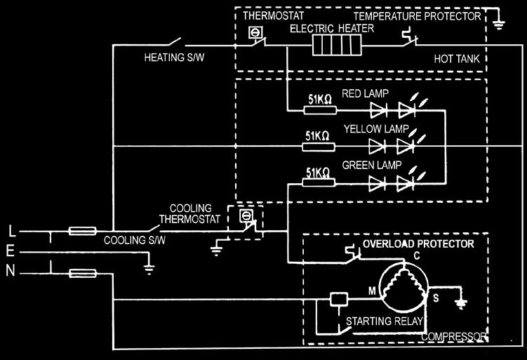
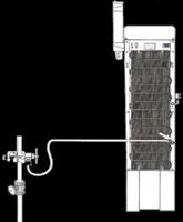
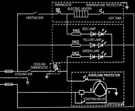
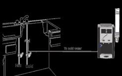


6 CIRCUIT AND INSTALLATION DIAGRAMS / Floor / Countertop Point of Use Water Coolers Circuit Diagram / Floor Point of Use Water Coolers Install to cold water supply line / Countertop Point of Use Water Coolers Install to cold water supply line 6


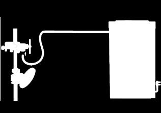
7 INSTALL WATER COOLER SYSTEM TO WATER SUPPLY 6 System Set-up & Preparation CAUTION: Adjust the cold water supply line at the T-Valve (Fig 1) by slowly turning the handle to reduce flow to the system. Connect the water supply line tubing to the system access board labeled water inlet. The system is shipped with a red cap; remove it before inserting the tube. Turn on the cold water supply line again. Make sure there is no leak at the connections. Recheck for water leaks. Plug the power cord into a receptacle outlet. Make sure the system is plugged into a 110 volt grounded outlet which contains a fuse or circuit breaker of 20 amps. Turn the shut-off valve handle to the ON position to allow the cold water to flow through the system. Check that water flows through the cold faucet; water will not flow if electrical is not plugged in. Allow the water to flow through the system. Check all connections including the filters and all other tubing and fitting connections inside the system for possible leaks. Dispense the hot and cold water faucet/spouts and run water until water flows freely and there is no air in the lines. Be careful: water from hot faucet can scald your hands. Allow water to flow through the system to refill the cold and hot tanks. Flush filters/membrane.* Turn on the hot and cold tank switches. Do not use the first three reservoirs of water. These flush the system. CAUTION: Flood stopper valve must be installed on the water cooler if the water cooler is installed in a high rise building. Recheck the system for water leaks. The following procedures will prepare the system to deliver the best possible drinking water Filters / RO Flushing Procedures* Esure that filters are installed, hot and cold switches are off, the system is plugged in, and the top of the cabinet and the reservoir lids are off. Allow water flow to fill the reservoir and drain the system three times. Avoid water spills, and use a pan to catch the water from both drains.* Refill the reservoir and cover cabinet by replacing lids. Turn both switches on after tanks are full. Dispense two glasses of water from each faucet/spout to clear trapped air. 8 A. Choose the valve location. Choose a location for the valve that is easily accessible. It is best to connect into the side of a vertical water pipe. When it is necessary to connect into a horizontal water pipe, make the connection to the top or side, rather than at the bottom, to avoid drawing off any sediment from the water pipe. Disconnect the cold water supply line. Attach and tighten the saddle valve connector assembly, being careful not to pinch or crimp any tubing or water supply line while tightening. Use Teflon tape to ensure a tight fit (Fig 2). NOTE: The saddle valve (Fig 2) clamps onto soft or hard tubing or pipe. It will make its own hole in copper tubing but not in iron or brass. For brass or galvanized iron pipe, drill a ¼ hole in pipe before mounting saddle valve. CAUTION: There is risk of electric shock. If possible, use a hand or cordless drill when drilling into the water pipe. Be sure that drill, cord, and outlet are all properly grounded. NOTE: Do not turn handle before installing or while installing saddle valve. To prevent damage to piercing needle, make sure that piercing lance does not project beyond the rubber gasket. NOTE: Leave handle in this position (valve closed) until filter installation is complete. B. Assemble saddle-tapping valve assembly on tube. 4. Hold back plate against tube. Hold saddle valve against tubing in a position directly opposite back plate. Tighten screw so saddle valve and back plate are held securely against tube. Tighten screw firmly. Do not crush tube. C. Connect source water feed tubing to valve body using compression fitting Installing the Saddle Valve Slide nut and sleeve onto tubing (in that order). Install insert into plastic tubing. Install tube with insert and sleeve into valve body. Thread compression nut onto valve body. Tighten. Turn saddle-tapping valve handle clockwise until it is firmly seated and piercing lance is fully extended. CAUTION: Supply line is pierced and valve is closed. Do not open valve until system is activated. Turn on cold water supply. Check saddle-tapping valve installation for leaks. Allow water to run from faucet for a few minutes to clear any debris in the line caused by installation. NOTE: If flow from sink faucet is reduced, clean faucet aerator. NOTE: Connect the water supply line tubing to the system access board labeled water inlet. The system is shipped with a red cap; remove it before inserting the tube. Fig 2 * NOTE: This drained water should be immediately disposed of properly (poured down a drain) to prevent accidental spilling, as this water will stain. T-Valve Installation WARNING: Water supply pressure must not exceed 60 psi. NOTE: T-Valve is designed for installation on flex line tubing. NOTE: Always check the local plumbing codes before tapping into a water line. Turn off cold water supply. Assemble T-Valve by screwing and tightening the shut-off valve into the water supply connector. Use thread tape on threads. Disconnect source water feed tubing from cold water supply. 4. Install T-Valve assembly in line with water feed tubing and water supply. 5. Remove nut from feed end of shut-off valve and slide over filter supply tubing. 6. Press end of tubing over exposed nipple on shut-off valve. Ensure it is completely seated. 7. Slide nut down tubing and tighten securely to shut-off valve. 8. Slowly turn on cold water supply and check for leaks. 9. Open T-Valve shut-off valve slowly to supply water to filter. For further instructions on T-Valve assembly, see T-Valve product label. Fig 1 7

. Pull the cartridge out of the main fold.")
. Loosen the connector fittings by turning them counterclockwise (Fig 8). 4. Pull the cartridge out of the main fold. 5.")
. Remove the membrane housing cap by turning counterclockwise.")
. 5.")


 and entire cooler with a new batch of sanitizing solution. 10.")
8 SERVICE INFORMATION AND GUIDELINES Feedwater Filtered Water Feedwater Filtered Water 9 Servicing the Filter (Fig 3) Shut off water at the water supply line. Turn off hot and cold water switches. Unplug the cord from outlet. 4. Drain tubing completely. 5. Disconnect tube from filter. CAUTION: HOT WATER WILL SCALD. 10 Changing Filter Cartridges Sediment Cartridge GAC Cartridge Ultrafiltration Cartridge Multi Stage Cartridge GAC Reverse Osmosis Ultrafiltration Multi Stage Cartridge Cartridge Cartridge Cartridge Loosen the connector fitting counterclockwise (Fig 4). Pull the cartridge out of the main fold. Wrap the connector fitting with Teflon tape and connect it to a new cartridge (Fig 5). Fig 6 11 Changing Cartridges in System Fig 4 Remove two screws from the back (Fig 6). Pull the lid up to locate the cartridge (Fig 7). Loosen the connector fittings by turning them counterclockwise (Fig 8). 4. Pull the cartridge out of the main fold. 5. Wrap the connector fitting with Teflon tape and connect it to a new cartridge (Fig 9). Fig 3 Fig 7 Fig 8 12 Changing Membranes Loosen the connector fitting counterclockwise (Fig 10). Remove the membrane housing cap by turning counterclockwise. Remove the membrane with a pincer (Fig 11). 4. Insert the membrane by carefully pushing the spigot end into the socket at the far end of the housing until completely in (Fig 12). 5. Wrap the connector fitting with Teflon tape and connect it to the tubing (Fig 13). 13 Sanitizing / Cleansing the System The back static condenser on the rear of the unit must be kept clean of dirt and lint. Visually inspect every 3 months. To clean it, follow these steps: a. Unplug the cooler. b. Clean condenser with a small, stiff, non-wire brush. Fig 10 Fig 11 Fig 13 Fig Fig 5 Sanitization Procedure Fig 9 Turn off hot and cold switches, then turn off water supply. Disconnect the power supply from the cooler. Drain hot-cold water tank and water from the reservoir by opening the system drain. 4. Drain water from the reservoir and hot tank (if fitted) through the faucets. 5. Wash hands thoroughly. 6. Put on disposable gloves. 7. Wash the faucets and reservoir using mild cleaning agent. Parts MUST be completely submerged in the solution. Rinse with clean water immediately. 8. Reassemble the water cooler using the sanitized components. 9. Sanitize hot and cold tank (if fitted) and entire cooler with a new batch of sanitizing solution. 10. Completely fill the cooler with sanitizing solution and let stand for 5 minutes. 1 Drain solution through hot and cold tank drain (if fitted) or through faucets. 1 Rinse with clean water immediately. 1 Reconnect the cold supply line to cooler s inlet tube. 14. Flush the reservoir at least three times to remove any traces of the sanitizing solution. 15. Use chlorine test kit to identify the presence of any contaminants. 16. If contamination still exists, repeat steps 13 and Clean the outside of the cabinet and the drip tray, using a mild cleaning agent. 18. Reconnect the power supply to the cooler. CAUTION: FAILURE TO TURN OFF HOT TANK COULD CAUSE PHYSICAL DAMAGE TO THIS UNIT. 8

 UV Light required or every 12-18 months required or every 18-24")
9 REPLACEMENT CARTRIDGES * The Reminder Decal is specially prepared as a reminder to change the cartridge routinely. Use a pen to fill out the installation and replacement dates. Peel off sticker and affix to the inside left or right panel of cartridge compartment. Cartridge #1 Sediment (All Floor Models) Ultrafiltration Cartridges FILTERS SERVICE LIFE PART # Cartridge #2 Granulated Activated Carbon Cartridge #3 UF Membrane Cartridge #4 Multistage Optional UV Light Cartridge #1 Granulated Activated Carbon Cartridge #2 RO Membrane Cartridge #3 UF Membrane Cartridge #4 Multistage (Optional) UV Light required or every months required or every months required or every months required or every months required or every months (All Floor Models) Reverse Osmosis Cartridges required or every months required or every months required or every months required or every months required or every months Countertop Replacement Cartridges required or every months CQE-RC CQE-RC CQE-RC CQE-RC CQE-UV CQE-RC CQE-RC CQE-RC CQE-RC CQE-UV CQE-RC


10 TROUBLESHOOTING GUIDE (Water Problems) Discovering the source of a problem is sometimes more difficult and time consuming than actually resolving the problem. There are two types of problems that call for correction: Parts or the system itself. Parts need to be set up correctly, repaired, or replaced. The system is not getting power, is receiving power at the wrong voltage, is being expected to perform beyond its capability, or simply needs to be cleaned. The troubleshooting chart below lists common symptoms and the conditions or parts that may be causing the symptoms, and discusses remedies for common problems that do not require repair work (power source, capacity, cleaning). Problem System Probable Cause Solution Checklist No water Not enough water Leak Water supply is turned OFF. Floater has tripped. Water supply is blocked. Clogged filter cartridges are restricting water flow. Fitting is not properly installed. Tubing is not pushed completely into fitting. Defective tube. Worn or damaged fitting and/or O-ring. The floater is stuck. Tube has burst. Water looks murky Cartridge(s) is/are depleted. Reservoir needs cleaning. Leak at filter Leak at water supply connector No indicator lights on No drain water Leaking drain assembly No hot water No cold water Water low flow (not enough water) Water has an offensive taste and/or odor Stem, fitting, and/or O-ring has nick or scratches. Cartridge(s) has/have cracks or scratches. Loosen water supply connector; loosen shut-off valve. Tubing deformed. The system is not plugged in. Hot and cold switches turned OFF. The connectors to switches are loose. Burned fuses. Clogged water drains. Hole or drain tube blockage. Drain plug or drain cover is not properly plugged or firmly tightened. The system is not plugged in. Hot tank switch is turned OFF. Burned out fuse. Connector to switch is loose. Hot tank switch is tripped. Circuit needs to be reset. Hot tank needs cleaning. Hot tank thermostat failed. Cold tank switch is turned OFF. Burned out fuse. Connector to switch is loose. Cold control. Water drawn in less time than the system can recover. Refrigerant loss. Low water pressure. Reservoir is depleted. Clogged sediment cartridge is restricting water flow. The system is not flushed properly. Carbon cartridge depleted. Sediment cartridge depleted. UF membrane depleted. TFC reverse osmosis membrane depleted. Turn water ON. Verify Crystal Quest water shut-off valve is open. Lift off cabinet top, remove reservoir s lid, and adjust the floater. Clear restriction, rotate valve handle on tap water feed valve and check the mechanical float. Replace Cartridge #3 and check the other cartridges. Reinstall. Push the tubing further onto fitting. Cut damaged area off tube or replace tube. Replace fitting and/or O-ring. Lift off cabinet top, remove reservoir lid, and adjust the fill float. Install flow-restrictor device and replace burst tube. Replace cartridges, clean and sanitize system. Drain reservoir, sanitize, and let it refill. Replace fitting and/or O-ring. Replace cracked cartridge(s) and install a flow-restrictor device. Tighten connections, reseal with Teflon tape, change O-ring. Cut damaged area off tube, or replace tube and sleeve. Plug the system into electrical outlet. Turn switches ON (reset). Lift off cabinet top, unplug, and replug wires from switches. Replace fuses. Clean the system. Remove drain plug. Replug the drain and tighten firmly. Plug the system into electrical outlet. Turn switches ON (reset). Replace fuse. Lift off cabinet top, unplug and replug wires from switch. Push the switch to reset. Turn switch OFF then back ON. Clean hot tank. Call Crystal Quest Service Center ( ). Turn switches ON (reset). Replace fuse. Lift off cabinet top, unplug and replug wires from switch. Adjust the level. Let the system run for 1-2 hours and recheck. Call Crystal Quest Service Center ( ). Check water supply line pressure. Unit will not operate at less than 173 kpa (25 psi). Consider additional coolers to meet water needs. Replace sediment cartridge. Empty the reservoir water three or more times. Replace activated carbon cartridge # Replace sediment cartridge #1 and sanitize/clean the system. Replace UF membrane #3 and sanitize the system. Replace TFC RO membrane #2 and sanitize the system. 10


11 TROUBLE SHOOTING GUIDE (Unit Problems) Problem No cold water and compressor rattling No cold water and compressor running Water too cold or frozen Unit runs noisily No hot water No water flow from hot faucet Check voltage received by cooler not running. Check cold control. Check wires. Check compressor relay. Check compressor overload. Check compressor. Check voltage received by cooler. Check for a refrigerant leak. Check for a restriction in capillary line or strainer. Check compressor. Check for a refrigerant leak. Water cooler is not level. Check for vibrations caused by loose screws. Check for vibrations at refrigeration lines. Check compressor. Check to make sure hot tank is turned on. Check voltage received by cooler. Check heat limiter. Check hot control. Check wires. Check hot tank heating element. Check water flow. Check hot faucet. Check for mineral build-up in hot tank. Solution Checklist 15 Safety Precautions 16 Easy Solutions ALWAYS UNPLUG THE SYSTEM BEFORE WORKING ON IT. The water coolers described in this manual operate on either 110 volts, 60 hertz single phase, or on 220/240 volts, 50/60 hertz single phase. Every effort should be made to avoid electric shock. ALWAYS SHUT OFF THE WATER FLOW AT THE WATER SUPPLY LINE BEFORE WORKING ON SYSTEM. When using a volt/ohm meter in the ohms mode, be sure the cooler is unplugged. 4. When using a volt/ohm meter in the AC volts mode, be sure the meter is set on a level sufficient for the voltage in use. 5. Check to be sure the outlet provides the voltage required by the cooler. Some problems have simple solutions. This section describes a couple of them. NON-WORKING SYSTEM: CHECKING THE VOLTAGE The easiest solution to a non-working system may be to plug the system s service cord into an electrical outlet. Although most solutions are not usually this simple to find, do not be lulled into forgetting to check this possible cause of trouble. Check Is the service plugged in? Is the switch controlling the outlet in the ON position? Test Plug in the cooler. Make sure any switch controlling the outlet is in the ON position. Remove the service cord from the wall outlet and plug in a radio or similar device. If the radio works, the outlet is good. Repair/Solution Incorrect voltage through the outlet may need to be corrected by the local utility company. Contacting the utility is the responsibility of the customer. NON-WORKING SYSTEM: CHECKING THE CUSTOMER S NEEDS WITH THE SYS- TEM S CAPACITY Under normal conditions, most coolers will produce 0 gallon of cold water (<10 C) per hour and a little more than 5 gallons of hot water (80 C-90 C) per hour. Check A. The temperature. If the temperature of the room containing the cooler or the temperature of the water in the cooler is below 32 F, the cooler will not be able to provide as much cold water within the standard amount of time. B. Amount of hot/cold water required in an average hour. Find out how many persons use the cooler each hour and what size cups they are filling. Calculate the total amount of water required in an average hour. C. Special customer needs for large amounts of water during certain periods of the day. For example, does the customer need 9 liters of cold water at 12:45 each afternoon to fill pitchers for meeting rooms? Does the customer need 18 liters of hot water early each day when coffee or tea is prepared? Repair/Solution If customer s water needs are exceeding the cooler s capabilities, consider adding another cooler. 11


12 ACCESS TO PARTS INSIDE THE SYSTEM 17 Acessing the System Inside Before beginning the service inspection and/or repair, remove the cooler top and back covers from the cabinet. The steps below outline the procedure for all removable reservoir coolers. To replace parts inside the cabinet: Shut off the water supply line to the system. Drain water through the back of the system. Unplug the power cord. 4. Remove the two top screws on back to remove the cover of the system. 5. Remove the top of the reservoir. 6. Remove the reservoir. 7. Remove the six inside screws attaching the back of the system to the cabinet. 8. Remove the two screws holding the fuse box cover in place. 9. Pull fuses to remove and replace. C. Accessing Switch Connectors Unplug the system. Remove two screws and remove the cabinet lid. Turn switches off. Unplug the connector and replug. Plug the cord back into wall socket. Turn the switch back on. D. Accessing Fuse Box 4. Unplug the system. Remove screws and remove back panel. Remove the fuse box cover. Remove fuse and replace. Switch Connectors Fuse Box Fuse Box Removing Cabinet Lid A. Removing Cabinet Lid Remove two screws from the back. Pull the lid up. Back Panel Fuse Box B. Accessing Fill Floater 4. Shut off the water at supply line. Drain water from the cooler completely. Remove the cabinet lid. Pull the reservoir lid up. Back Panel Fuse Box Spouts/Faucets Cold Water Switch Hot Water Switch Cold Water Switch Hot Water Switch Drip Tray E. Replacing Spouts/Faucets ( only) Turn the knob counterclockwise to unscrew. Pull up and remove. F. Removing Drip Tray Pull up and remove. G. Draining the System Unscrew the drain cap and remove the drain plug. Place a pan, bucket, etc. beneath to catch water. System Drain System Drain 12


 that secure face of machine to the body.")
13 ACCESS TO HEATING RESERVOIR Water Cooler Heating Reservoir Replacement Guide Water Cooler Heating Reservoir Replacement Guide NOTICE: Ensure both heating and cooling switches are turned off, power cord is unplugged from wall and water supply is turned off before servicing the machine to avoid damage or injury. Preparation Turn off both the heating and cooling switches located on back of water cooler. Unplug power cord from electrical socket. Turn off water supply. Disconnect water supply line from back of cooler. Drain cooler completely of water using drain plug located on back of unit. Remove top from cooler, exposing the cooling reservoir; there are two screws on the back that secure the top to the machine. Disassembly Disconnect the water line from the cooling reservoir. Unplug wiring at plug for electronic float; this is the small black wire feeding from the cooling reservoir lid. Remove the cooling reservoir lid by pulling up on one edge of it. Remove the two metal ties that secure the foam sides of the cooling reservoir. Save these for reassembly. Remove both foam sides that cover cooling reservoir. Remove six screws (two on inside near cooling reservoir and two behind drip tray on front) that secure face of machine to the body. Disconnect cold water and hot water supply hoses from inside of face. Remove cooler front face. This allows easy removal of reservoir and better working room. Remove the 4 screws that secure the condenser coils (black grate) to the back of the machine. Gently pull out on one side of the coil to allow room to access heating reservoir. CAUTION: Pulling out too much on coil will damage coil and cooling system. Make labels or draw a diagram for wiring on heating reservoir; this will aid in reassembly. Disconnect wiring from heating reservoir. Disconnect drain hose from reservoir. Disconnect supply hose from reservoir. This hose runs from bottom of cooling reservoir to side of heating reservoir. Disconnect vent hose from top of heating reservoir. Locate the two screws that secure heating reservoir to body. These screws are underneath the foam base of the cooling reservoir. You may need to break off a small piece of this base to locate the screws. Save this piece for reassembly. Remove both screws which will allow you to remove the entire heating tank from the front of the machine. Install new reservoir in reverse order of removal. Once installed and cooler is reassembled completely, reattach water supply and plug unit into electrical outlet. NOTE: Do not turn the cooling and heating switches on until at least two cups of water can be retrieved from each spout. Damage to heating and cooling system can result. Preparation Turn off both the heating and cooling switches located on back of water cooler. Unplug power cord from electrical socket. Turn off water supply. Disconnect water supply line from back of cooler. Drain cooler completely of water using drain plug located on back of unit. Remove hot water spout from face of unit by turning spout counterclockwise. Remove cold water spout. Remove top from cooler exposing the cooling reservoir; there are two screws on the back that secure the top to the machine. Disassembly Disconnect the water line from the cooling reservoir. Unplug wiring at plug for electronic float; this is the small black wire feeding from the cooling reservoir lid. Remove the cooling reservoir lid by pulling up on one edge of it. Remove the two metal ties that secure the foam sides of the cooling reservoir. Save these for reassembly. Remove both foam sides that cover cooling reservoir. Remove six screws (four on inside near cooling reservoir and two behind drip tray on front) that secure face of machine to the body. Remove cooler front face. This allows easy removal of reservoir and better working room. Remove the four screws that secure the condenser coils (black grate) to the back of the machine. Gently pull out on one side of the coil to allow room to access heating reservoir CAUTION: Pulling out too much on coil will damage coil and cooling system. Make labels or draw a diagram for wiring on heating reservoir; this will aid in reassembly. Disconnect wiring from heating reservoir. Disconnect drain hose from reservoir. Disconnect supply hose from reservoir. This hose runs from bottom of cooling reservoir to side of heating reservoir. Disconnect vent hose from top of heating reservoir. Locate the two screws that secure the heating reservoir to body. These screws are underneath the foam base of the cooling reservoir. You may need to break off a small piece of this base to locate the screws. Save this piece for reassembly. Remove both screws; take off the entire heating tank from the front of the machine. Install new reservoir in reverse order of removal. Once installed and cooler is reassembled completely, reattach water supply and plug unit into electrical outlet. NOTE: Do not turn the cooling and heating switches on until at least 2 cups of water can be retrieved from each spout. Damage to heating and cooling system can result. Please record the information below for your future reference Plumber s Name Plumber s Address Plumber s Telephone 13

14 WATER COOLERS (OPTIONAL CARTRIDGES & ACCESSORIES) CQE-OZ Crystal Quest Ozonator Sterilizer System Automatically sanitizes the cooler through a burst of ozone into the cooling tank and system. Ozonation kills any bacteria in a safe, odorless and taste free way. Ozone is a natural sterilization process that ensures your water is bacteria free. Once ozone has finished its sterilization job, it dissipates as oxygen and leaves your water oxygen enriched. Crystal Quest Power Stabilizer CQE-PS The amount of power required for a Crystal Quest Bottleless Water Cooler to operate is as follows: 110 Volts 60 Hertz Heating System 500 Watts 6.2 Amps Cooling System 112 Watts 4 Amps Total 612 Watts 8.6 Amps This power requirement must be supplied at a constant rate to avoid damage. If a constant rate cannot be guaranteed then a power stabilizer is available to ensure this constant power requirement. CQE-PS Leak Detector Smart Valve This Leak Detector Smart Valve claims to detect a water leak within a water cooler and shuts down the water supply in order to prevent flooding. The sensor is mounted inside the cartridge area of the cooler. If it detects wetness from a leak, it shuts down the water supply at the control box. The Leak Detector Valve is a valuable tool in helping to prevent damage that can occur in the event that a leak occurs within the water cooler. Crystal Quest CQE-PT Cup Holder Crystal Quest CQE-RC Crystal Quest Alkalizer/Ionizer, Mineralizer and Oxidation Cartridge-Sealed Crystal Quest CQE-RC Crystal Quest Water Cooler/Reverse Osmosis Fluoride Water Filter Cartridge Crystal Quest CQE-RC Oz Paper Cups Crystal Quest CQE-RC Crystal Quest Water Cooler/Reverse Osmosis Nitrate Water Filter Cartridge Crystal Quest CQE-RC Crystal Quest Water Cooler/Reverse Osmosis Arsenic Water Filter Cartridge (Available in quantities of 50 or 100) 14


15 Crystal Quest warrants your Crystal Quest Point of Use Bottleless Water Coolers for one year from the date of purchase against all defects in materials and workmanship when used in compliance with the manual. This warranty does not include replacement cartridges unless defective upon receipt. Crystal Quest disclaims all implied warranties including, without limitation, warranties of merchantability and fitness for a particular purpose. If for any reason the product proves to be defective within one year from the date of purchase, please call for assistance. This warranty gives you specific legal rights and you may have other legal rights which vary from state to state. Crystal Quest assumes no responsibility for incidental or con- sequential damages, for damages arising out of misuse of the product, or the use of any unauthorized attachment. Some states do not allow the exclu- sion or limitation of implied warranties or incidental or consequential damages; therefore, the above limitations or exclusions may not apply to you. Should service be required during or after the warranty period or should you have any questions regarding how to use your Crystal Quest Point of Use Bottleless Water Coolers, please contact our Technical Support Department at service@crystalquest.com, Monday through Friday, 9 AM to 5 PM Eastern Time. IMPORTANT NOTICE: The unit was inspected and properly packaged before leaving Crystal Quest facilities and was free of any damage. Upon delivery, immediately inspect the carton and product/s for evidence of rough handling and concealed damages. Report any damage to the carrier (company which delivers the product/s to customer), and file damage claims with the carrier immediately. Remove the carton, top packaging tray, and shipping bag from the system. Then remove the unit from the bottom Styrofoam and carton tray. Make sure to inspect the system further, ensuring that: a) there are no marks or physical damage to the system. b) all accessories are present. c) the hot tank switch is in the OFF position. All packages are insured. Should damaged merchandise arrive to you, you must take the following steps and file a claim with the carrier to avoid claim delays or denial. Purchaser is responsible for filing a claim with the carrier directly. If product was damaged during shipment, keep the original shipping cartons, packaging materials, and content; contact the carrier and request they pick up and return to Crystal Quest for replacement. Also, file a claim with the carrier immediately. It is vital that you inspect the merchandise upon arrival and report the damage to the carrier to avoid denial or delay of claim. All claims for shipping damages must be made within five business days from delivery. If the merchandise was dropped off at your location (this is determined by seeing that the tracking information has a delivered status), Crystal Quest cannot be held liable or responsible for lost, stolen, or damaged goods. Crystal Quest cannot be held responsible or liable for damage to your property occurring during delivery by delivery company. NOTE: Make sure the product has been standing in an upright position for 24 hours prior to installation. GENERAL PROVISIONS AND EXCLUSIONS This warranty applies only within the continental limits of the United States of America and Canada. This warranty does not apply if service of the sealed refrigeration system or cold system or parts furnished as original equipment by Crystal Quest is not obtained from approved service center or the factory. This warranty does not apply to any water components that become inoperative due to limiting conditions. This warranty does not apply to any water cooler or components that become inoperable because of a failure to satisfy standards or regulations adopted by any government or agency thereof subsequent to the date of shipment. This warranty does not cover performance, failure, or damage of any part resulting from external cause such as alteration, abuse, misuse, misapplication, corrosion, or act of God. WARNING The warranty and the CE listing for this machine are automatically voided if this machine is modified or combined with any other machine or device. Alteration or modification of this machine may cause serious flooding and/or hazardous electrical shock or fire. Except as set forth herein, the Manufacturer makes no other warranty, guarantee, or agreement expressed, implied or statutory, including implied warranty of merchantability or fitness for a particular purpose. The foregoing is in lieu of all other agreements expressed, implied or statutory and all obligations or liabilities of the Manufacturer. The Manufacturer does not assume or authorize any person to assume any obligations of liability in connection with this product. In no event will Manufacturer be liable for special or consequential damages or for any delay in the performance of this agreement due to causes beyond their control. FILTER AND R/O MEMBRANE / LIMITED WARRANTY / FILTER WARRANTY Subject to conditions and limitations described below, Crystal Quest warrants the filters to be free from defects in material and workmanship under normal use within the operating specifications in the Installation and Operation Guide. R/O MEMBRANE WARRANTY Membranes carry a twelve-month prorated warranty as follows: Credit 1/12th of the replacement cost for each unused month the system is installed and maintained to factory instructions and the unit is operated within the specifications listed in the filter Installation and Operation Guide. Filters/cartridges/membranes under warranty will be repaired or replaced and returned upon inspection by Crystal Quest. CONDITIONS OF FILTER WARRANTY The above warranty will not apply to the filters, cartridges, or R/O membranes that are damaged because of neglect, misuse, alteration, accident, and misapplication, fouling, and/or scaling of membrane by minerals, bacteria attack, sediment, or damage caused by fire, act of God, freezing, or hot water. If the filters/cartridges/membranes is/are altered by anyone other than Crystal Quest, the warranty is voided. Crystal Quest assumes no warranty liability in connection with the reverse osmosis or filter system other than specified herein. Crystal Quest will not be liable for any consequential damages of any kind or nature of Crystal Quest products. 15


16 A TASTE OF NATURE To order replacement cartridges, contact your Crystal Quest Dealer or visit us online at: Your Purchase Information Installation and Maintenance Instructions KEEP THIS MANUAL FOR FUTURE REFERENCE AND UNIT MAINTENANCE To register your product warranty online visit To review the latest edition of the Installation and Operation Guide, visit Product design is subject to change without notice. For further assistance contact your Crystal Quest Dealer or us at 16 Copyright 2011 Crystal Quest All rights reserved.
Crystal Quest Point-of-Use Bottleless Water Cooler INSTALLATION AND OPERATION GUIDE
 Crystal Quest Point-of-Use Bottleless Water Cooler INSTALLATION AND OPERATION GUIDE MODELS: CQE-WC-05901 CQE-WC-05903 CQE-WC-00906 CQE-WC-05907 CQE-WC-05908 CQE-WC-00900 CQE-WC-05902 CQE-WC-05909 CQE-WC-00910
Installing the Turbo Floor Model System
 Installing the Turbo Floor Model System Location 1. Locate as close as possible to water supply source. 2. Locate as close as possible to a three-prong grounding receptacle. 3. Locate the System on a smooth
Installation & Service Guide
 Reverse Osmosis Ontario Soft Water.ca Kitchener, Canada 519-579-0500 Installation & Service Guide Pentair 75 gpd Encapsulated Membrane System Standard System 75gpd Membrane Your New Reverse Osmosis System
PWC 7000 PureWaterCooler SERVICE MANUAL. for. PureWaterCooler by Vertex Model Copyright 2012 Vertex Water Products
 SERVICE MANUAL for by Vertex Model 7000 Table of Contents 1. Introduction 2. Cooler Set-up 3. Top Cover Removal 4. Remove/Replace Mechanical Float Valve Assembly 5. Removing/Replacing Control Panel and
INSTALLATION & SERVICE MANUAL
 INSTALLATION & SERVICE MANUAL Countertop Reverse Osmosis Systems Series CT System Tested and Certified by WQA against NSF/ANSI Standard 58 for the reduction of Arsenic, Barium, Cadmium, Copper, Cyst, Hexavalent
INSTALLATION MANUAL CT-200
 INSTALLATION MANUAL CT-200 1 CHILLER SAFETY Your safety and the safety of others are very important. We have provided many important safety messages in this manual and on your appliance. Always read and
Alkaline RO System INSTALLATION MANUAL
 Alkaline RO System INSTALLATION MANUAL 1-800-992-8876 Customer Support Disclaimer All rights reserved. All material published on this site by Express Water Inc., including all portions of the website,
Installation & Operating Guide
 5-036 HOT WATER TANK Installation & Operating Guide Read all instructions thoroughly. Keep this guide for future reference. Proof of purchase is required for Warranty. Staple receipt or proof of purchase
WATERSHIELIJrM REVERSE OSMOSIS INSTALLA TION MANUAL ~ ~ ~ ~ ~ l ~ TO INSURE THIS PRODUCT AND THE INSTALLATION THEREOF. ~ ~ ~ ~ ~
 WATERSHIELIJrM REVERSE OSMOSIS SYSTEM INSTALLA TION MANUAL p 1 ~ -~ I IMPORTANT I ITHIS REVERSE OSMOSIS SYSTEM WAS SOLD IN KIT FORM. IT HAS ~ INOT BEEN PRESSURE TESTED IN ANY WAY. UPON INSTALLATION IT
MKTF CRO-Series 5-Stage Reverse Osmosis System Installation and Maintenance Manual
 MKTF - 215 CRO-Series 5-Stage Reverse Osmosis System Installation and Maintenance Manual Please fill out the following information at the time of installation. Save for future reference. Model: Date Code:
OWNE R S MA N UA L. Made in USA. September 2015
 September 2015 OWNE R S MA N UA L Made in USA www.drinkableair.com OWNER S MANUAL Warranty 02 Atmospheric Water Generators (AWGs) 03 Safety Precautions 04 Operational Diagram & System Specs 05 Getting
Table of Contents. List of Figures
 1 P a g e Table of Contents Introduction. 3 Receiving....4 Description Model G3 & G4...5/6 Water Production Flow Chart...7 Positioning the Cooler...8 Water Cooler Connections..9 Feed Water Connection....10
1 P a g e. G4 Counter Top OPERATION MANUAL
 1 P a g e G4 Counter Top OPERATION MANUAL Table of Contents Introduction. 3 Receiving....4 Description Model G3 & G4...5/6 Water Production Flow Chart...7 Positioning the Cooler...8 Water Cooler Connections..9
REMOTE FAUCET PUMP SYSTEM
 REMOTE FAUCET PUMP SYSTEM Use & Care Guide See Important Safeguards on Page 2 An exclamation point within an equilateral triangle is intended to alert user to the presence of important operating and maintenance
WA A Aqua Sub Bottom-load Water Cooler
 WA1-02-21A Aqua Sub Bottom-load Water Cooler 4002638 Thank you for choosing a Soleus Air Water Cooler. This owner s manual will provide you with valuable information necessary for the proper care and maintenance
475 PRO SERIES Reverse Osmosis System Installation & Operation Manual
 PLEASE READ ALL INSTRUCTIONS BEFORE INSTALLING AND USING THIS SYSTEM 475 PRO SERIES Reverse Osmosis System Installation & Operation Manual Model STAGE 1 STAGE 2 STAGE 3 STAGE 4 OUTPUT 475 SEDIMENT CARBON
PWC-500/1000/1010/1500
 SERVICE MANUAL for by Vertex Model PWC-500/1000/1010/1500 P/N man-7008 Table of Contents 1. Introduction 2. Cooler Set-up 3. Remove Top Cover 4. Remove/Replace Float 5. Remove/Replace Hot Tank 6. Faucet
REVERSE OSMOSIS DRINKING WATER SYSTEM
 REVERSE OSMOSIS DRINKING WATER SYSTEM 10/10 1 2 Introduction To The Sierra Congratulations on your purchase of the Nimbus Sierra reverse osmosis system. When properly maintained, this system will provide
Water Distillation System Instruction Manual Nutriteam TC-501
 Water Distillation System Instruction Manual Nutriteam TC-501 Thank you for purchasing the Nutriteam TC-501 Water Distillation System. It will provide your household with freshly made, ultra clean, great
Owners Manual. 900 Series Drinking Water Appliance
 Owners Manual 900 Series Drinking Water Appliance Package Contents Installation Kit Owner s Manual Power Cord Elbow fitting Shutoff valve 10 ft. Blue Tubing Models 903 & 904 include 6 ft. green tubing
PRE INSTALLATION PROCEDURES
 PRE INSTALLATION PROCEDURES DANGER! ELECTRICAL SHOCK HAZARD. Only qualified personnel who have read and understand this entire manual should attempt to install, or service this WL250 Water Treatment System,
Instruction Manual. Pressure Washer. Get ready to deep clean! Wards.com Wards.com ITEM:
 Get ready to deep clean! Pressure Washer Montgomery Ward Customer Service 3650 Milwaukee Street, Madison, WI 53714 8:00 am to Midnight, Monday through Friday Wards.com Instruction Manual ITEM: 751821 Wards.com
INSTALLATION AND OPERATING INSTRUCTIONS FOR RW519 RAIN WATER FILTRATION SYSTEM
 INSTALLATION AND OPERATING INSTRUCTIONS FOR RW519 RAIN WATER FILTRATION SYSTEM INSTALLATION CAUTIONS Installation must conform to all local and state plumbing codes and regulations. Please read carefully
Instant Hot Water Dispenser Owner s Manual
 Model Hot1 Instant Hot Water Dispenser Owner s Manual Installation, Care & Use Instalacion, cuidado & uso Installation, soin et utilisation WHAT YOU SHOULD KNOW BEFORE YOU BEGIN For your satisfaction and
DELUXE COLLECTION Executive Filtered Water Cooler AQP-WCM-FBOT4
 DELUXE COLLECTION Executive Filtered Water Cooler AQP-WCM-FBOT4 Congratulations on your purchase of an Aquaport Executive Filtered Water Cooler This unit is easy to install and provides great tasting chilled
SAFETY ALERT SYMBOLS SAFETY PRECAUTIONS
 SAFETY ALERT SYMBOLS Read and follow all safety information carefully. The signal words used in this manual are selected as shown below and based on an assessment of the degree of potential injury or damage
Controlled Energy Corp. 340 Mad River Park Waitsfield, VT TOLL FREE
 Controlled Energy Corp. 340 Mad River Park Waitsfield, VT 05673 TOLL FREE 866-330-2729 www.controlledenergy.com/tech Important Safety Instructions When using this electrical equipment, basic safety precautions
A910.8A Remote Water Chiller, 8 GPH A A / A A-220V TECHNICAL ASSISTANCE TOLL FREE TELEPHONE NUMBER:
 Remote Water Chiller, 8 GPH A9100080-A / A9100080-A-220V TECHNICAL ASSISTANCE TOLL FREE TELEPHONE NUMBER: 1.800.591.9360 Technical Assistance Fax: 1.626.855.4894 NOTES TO INSTALLER: 1. Please leave this
WHOLE HOUSE FILTER &
 INSTALLATION, OPERATION AND MAINTENANCE MANUAL Warning Please read carefully before proceeding with installation. Your failure to follow any attached instructions or operating parameters may lead to the
APEX Water Filters MODEL RO 5. Treat your body to pure goodness with Apex filtered water INSTRUCTION MANUAL. pure water in every drop
 APEX Water Filters pure water in every drop MODEL RO 5 INSTRUCTION MANUAL Treat your body to pure goodness with Apex filtered water A Water supply adapter valve B Cold water shut-off valve C Hot water
INSTALLATION, OPERATION AND MAINTENANCE INSTRUCTIONS
 INSTALLATION, OPERATION AND MAINTENANCE INSTRUCTIONS AquaArctic Remote Water Chiller A9100080 -A TECHNICAL ASSISTANCE TOLL FREE TELEPHONE NUMBER: 1.800.591.9360 Technical Assistance Fax: 1.626.855.4894
SAFETY ALERT SYMBOLS SAFETY PRECAUTIONS
 SAFETY ALERT SYMBOLS Read and follow all safety information carefully. The signal words used in this manual are selected as shown below and based on an assessment of the degree of potential injury or damage
Installation & Operating Guide
 HOT WATER DISPENSER Installation & Operating Guide Read all instructions thoroughly. Keep this guide for future reference. Proof of purchase is required for Warranty. Staple receipt or proof of purchase
Industrial Vacuums, Inc
 Instructions/Spare Parts Manual Nilfisk Model GWD255 Drum Top Vacuum CAUTION: This Nilfisk vacuum cleaner is not to be used in explosion-hazardous areas, as serious injury could result. Under no circumstances
B.I.C.A Built-In Coffee Appliance
 B.I.C.A Built-In Coffee Appliance Automatic Coffee Brewer Parts & Service Models: 1033510, 1033510S & 1033511 3828 S. Main St. Los Angeles, CA 90037-1491 800-421-6860 310-787-5444 Fax 310-787-5412 e-mail:
OWNER S MANUAL & WARRANTY
 OWNER S MANUAL & WARRANTY CONTAINS IMPORTANT PRODUCT INFORMATION FOR MODELS: Premier Lil Premier Lil Delux Kiddie Station Advantage Series Nature Series Silver Series IMPORTANT! Experiencing Any Set-Up
SERVICE MANUAL. Bradford White ElectriFLEX HD (Heavy Duty) Commercial Electric Water Heater CEHD SERIES Immersion Thermostat Models
 Commercial Electric Water Heater CEHD SERIES Immersion Thermostat Models") Bradford White ElectriFLEX HD (Heavy Duty) Commercial Electric Water Heater CEHD SERIES Immersion Thermostat Models SERVICE MANUAL Troubleshooting Guide and Instructions for Service (To be performed ONLY
Bradford White ElectriFLEX HD (Heavy Duty) Commercial Electric Water Heater CEHD SERIES Immersion Thermostat Models SERVICE MANUAL Troubleshooting Guide and Instructions for Service (To be performed ONLY
OWNERS MANUAL For IN ROOM BREWING SYSTEM MODEL REFILLABLE CAPSULES K901. Includes: Installation Use & Care Servicing Instructions
 634 10 Sunnen Drive St. Louis, MO 63143 telephone: 314-678-6336 fax: 314-781-2714 www.bloomfieldworldwide.com OWNERS MANUAL For IN ROOM BREWING SYSTEM MODEL REFILLABLE CAPSULES K901 Includes: Installation
USER S MANUAL. MODEL NO. CLTL100 (White) CLTL120 (Black) Top-Load Water Cooler
 CLTL120 (Black) Top-Load Water Cooler") USER S MANUAL MODEL NO. CLTL100 (White) CLTL120 (Black) Top-Load Water Cooler Thank you for purchasing a Lago water cooler. Please read this user s manual thoroughly for using the water coolers safely
USER S MANUAL MODEL NO. CLTL100 (White) CLTL120 (Black) Top-Load Water Cooler Thank you for purchasing a Lago water cooler. Please read this user s manual thoroughly for using the water coolers safely
CHILLER DADDY MODEL: CHL-501 Intended Use For: Residential & Office Water Chiller
 CHILLER DADDY MODEL: CHL-501 Intended Use For: Residential & Office Water Chiller OWNER S MANUAL TABLE OF CONTENTS 1. FOR YOUR SAFETY 2. LOCATION REQUIREMENTS 3. INSTALLATION PROCEDURES 4. PRESSURE LIMITER
INSTANT HOT WATER DISPENSER
 INSTANT HOT WATER DISPENSER Tank Installation Materials required (not provided) 2 mounting bracket screws (and 2 plastic anchors if attaching to drywall) Shut-Off valve and T fitting Components When you
Air Cleaning Equipment, Inc. 303 N. Main St. Broadway, NC iers.com
 Read and Save These Instructions Horizon Galaxy - Installation and Operations Manual Air Cleaning Equipment, Inc. 303 N. Main St. Broadway, NC 27505 www.horizondehumidif iers.com 1 Safety Notes: The Horizon
48 MaxxAir Portable Evaporative Cooler Owner s Manual
 48 MaxxAir Portable Evaporative Cooler Owner s Manual This Manual covers all of the following MaxxAir Portable Evaporative Coolers. EC48D1 MaxxAir 48 Belt Drive 2 Speed File this owner s manual in a safe
CSD-1 CRN Electra Steam, Inc. Instruction Manual for JR06 Steam Generator, JG- and JJ- Models
 ASME CSD-1 CRN Electra Steam, Inc. Instruction Manual for JR06 Steam Generator, JG- and JJ- Models RETAIN THIS OPERATING MANUAL WITH BOILER. DO NOT DISCARD READ THIS FIRST: The safeguards and instructions
SERVICE/INSTALLATION MANUAL ICE ONLY DISPENSERS MODELS-IOD150, IOD200 AND IOD250
 SERVICE/INSTALLATION MANUAL ICE ONLY DISPENSERS MODELS-IOD150, IOD200 AND IOD250 Ice-O-Matic 11100 East 45th Ave Denver, Colorado 80239 Part Number 9081305-01 Date 10/08 Introduction IOD150,IOD200,IOD250
5-Stage Reverse Osmosis System
 5-Stage Reverse Osmosis System 41840 McAlby Court, Suite A Murrieta, CA 92562 800-451-9343, FAX 951-894-2801 www.nimbuswater.com 02/09 1 Introduction to the WaterMaker Five Congratulations on your purchase
IMPORTANT SAFETY INSTRUCTIONS EC-AG1-25 EC-AG1, EC-AG2 SAVE THESE INSTRUCTIONS.
 IMPORTANT SAFETY INSTRUCTIONS 2 1. Read and Follow All Instructions 2. Read this manual completely before attempting installation. 3. All permanent electrical connections should be made by a qualified
IMPORTANT! ank You! Model: Twist-In 100 GPD, 3-Stage RO Unit. Installation, Operation & Maintenance Guide
 Twist-In 00 GPD, 3-Stage RO Unit WARNING: Please read carefully before proceeding with installation. Your failure to follow any attached instructions and operating parameters may lead to the product s
 PROBLEM POSSIBLE CAUSES SOLUTIONS The motor seems to run too much The lights do not work High efficiency compressor and fans The room or outdoor temperature is hot A large amount of warm food has been
Whynter Portable Ice Maker 33 lb capacity - White
 Whynter Portable Ice Maker 33 lb capacity - White Model # : IMC-330WS INSTRUCTION MANUAL Congratulations on your new Whynter product. To ensure proper operation, please read this Instruction Manual carefully
2-Stage Under Counter Filtration System Model: WP-2 LCV
 INSTALLATION, OPERATION AND MAINTENANCE MANUAL Save manual for future reference 2-Stage Under Counter Filtration System Model: WP-2 LCV IMPORTANT If you are unsure about installing your WATTS water filter,
Compact Refrigerator. User Manual Model 3590A
 By Compact Refrigerator User Manual Model 3590A DANGER Risk of child entrapment. Before you throw away your old refrigerator or freezer, take off the doors. Leave the shelves in place so that children
 http://waterheatertimer.org/how-to-install-under-counter-water-heater.html 1 IMPORTANT SAFETY INSTRUCTIONS Warning When using electrical appliances, basic safety precautions to reduce the risk of fire,
gamma pond Ultraviolet Sterilizers
 gamma pond Ultraviolet Sterilizers Instructions for Models #1410 8w, 1411 15w, 1412 25w, 1403-40w Important Safety Instructions... Page 2 Installation... Page 3 Maintenance & Winterizing... Page 5 Warranty...
One-Touch Dispense. Multi-temp selections. 208 F For tea, coffee, instant noodle. 194 F Keep warm around 194 F. 176 F Keep warm around 176 F.
 Instruction Manual Automatic Dispensing Hot Water Pot with Multi-temperature Function Automatic Dispensing One-Touch Dispense FEATURES Reboil Function 5 Temperature Settings Image Of SP-5016 208 F For
4.9 CU.FT. BEER KEG COOLER INSTRUCTION MANUAL. Model No.: MCKC490S
 4.9 CU.FT. BEER KEG COOLER INSTRUCTION MANUAL Model No.: MCKC490S To ensure proper use of this appliance and your safety, please read the following instructions completely before operating this appliance.
CP-JR STILL WATER CHILLER SYSTEM DESCRIPTION
 CP-JR STILL WATER CHILLER SYSTEM DESCRIPTION Congratulations on the purchase of your Crysalli system. The Crysalli CP-JR-SW Still Water chiller, with CR-12FC Water Filter System are a configuration designed
18 MaxxAir Portable Evaporative Cooler Owner s Manual This Manual covers the EC18DVS MaxxAir Portable Evaporative Cooler.
 18 MaxxAir Portable Evaporative Cooler Owner s Manual This Manual covers the EC18DVS MaxxAir Portable Evaporative Cooler. File this owner s manual in a safe place for future reference. It contains operating
Installation & Operating Instructions
 PREMIUM Installation & Operating Instructions m AQP-3TAP-SS Platinum Water Dispenser Hot/Cold & Room Premium Selection Congratulations on your purchase of an Aquaport Platinum Water Dispenser Thank you
Installation and Operating Instructions
 Installation and Operating Instructions WaterQuick Pro II Advanced - Hot Water Circulation Pump WaterQuick Pro II Advanced Step 1. Choose the appropriate place to install the pump and Flow Monitor: WaterQuick
Garment Steamer Model SC620
 OWNER S MANUAL Garment Steamer Model SC620 For information or assistance: EURO-PRO Corporation 178 West Service Rd. Champlain, NY 12919 1-800-798-7398 www.euro-pro.com IMPORTANT SAFETY INSTRUCTIONS When
Installation & Service Manual
 Installation & Service Manual Table of Contents Unpacking & Inspection... 2 Basic Guidelines... 2 Specifications... 3 Before Starting Installation Where to install the filter... 4 Tools, pipe, fittings
WL380 QUICK START GUIDE
 WL380 QUICK START GUIDE WARNING! Only trained and qualified technicians should attempt to install, maintain, or service Waterlogic equipment. Failure to follow all instructions in this manual could result
PWC 1800 PureWaterCooler SERVICE MANUAL. for. PureWaterCooler by Vertex Model PWC P/N man Copyright 2011 Vertex Water Products
 SERVICE MANUAL for by Vertex Model PWC-1800 P/N man-7011 Table of Contents 1. Introduction 2. Cooler Set-up 3. Remove Top Cover 4. Remove/Replace Float 5. Remove/Replace Hot Tank 6. Dispensing Solenoid
INSTALLATION & SERVICE MANUAL
 INSTALLATION & SERVICE MANUAL Countertop Reverse Osmosis Systems Series CT CT-315 CT-315TFC CT-445 CT-445P CT-D425 CT-D425P CT-550UP 3 STAGE CTA RO SYSTEM 3 STAGE TFC RO SYSTEM 4 STAGE TFC RO SYSTEM 4
A few simple steps to ensure perfect water, every time.
 A few simple steps to ensure perfect water, every time. Use and Care Guide MODELS: A7BOTTLELESS A7BOTTLELESSBLK Registration Please visit the website below to register your new water cooler within the
SEABREEZE. SeaBreeze Rain Shower System Model #1086-CH Owner's Manual
 SEABREEZE SeaBreeze Rain Shower System Model #1086-CH Owner's Manual SeaBreeze Model #1086 Please Read The Following Instructions COMPLETELY Before Beginning! Our goal is to ensure your installation goes
Instruction Manual Item No.: V~, 60Hz
 Energy- Saving Mode Portable AC 10,000 BTU Model: MW-L3-10C Montgomery Ward Customer Service 1112 7th Avenue, Monroe, WI 53566 8:00 am to Midnight, Monday through Friday 1 888 557 3848 Instruction Manual
InstructIon Manual KrEs EQuIPMEnt stands
 Instruction Manual Instruction Manual SELF-CONTAINED AND REMOTE Kairak KRES model refrigerated equipment stand units are available in many lengths from 36 to 120 inches long. These units are available
SEISCO SUPERCHARGER EXTENDER/BOOSTER INSTALLATION GUIDE & OWNERS MANUAL
 SEISCO SUPERCHARGER EXTENDER/BOOSTER INSTALLATION GUIDE & OWNERS MANUAL This manual is provided as a guide to installation. All installations must comply with any and all local and national electrical
12,000 BTU Evaporative Portable Air Conditioner
 12,000 BTU Evaporative Portable Air Conditioner Owner s Manual Model # KY-32E Please read owner s manual carefully before operating the unit. TABLE OF CONTENTS PAGE Table of Contents. 2 Introduction....3
Installation & Operating Instructions
 PREMIUM Installation & Operating Instructions AQP-20SIL Signature Filtered Water Cooler Premium Selection Congratulations on your purchase of a Aquaport Signature Filtered Water Cooler This unit is easy
Hot-1 Hot Water Dispenser
 The Installation, Care and Use of Your New Hot-1 Hot Water Dispenser Valve lever design may vary How your hot water dispenser works Water is electrically heated to a brewing/cooking hot 190 F (88 C)* by
Fully Automatic Water Softeners
 OWNERS GUIDE TO INSTALLATION AND OPERATION Fully Automatic Water Softeners SINGLE TANK CABINET MODELS TWO TANK MODELS Read the instructions carefully and learn the specific details regarding installation
RK/ RK Oxygen Detector Operator s Manual
 65-2494RK/65-2497RK Oxygen Detector Operator s Manual Part Number: 71-0179RK Revision: 0 Released: 2/16/11 www.rkiinstruments.com WARNING Read and understand this instruction manual before operating detector.
RCM-77. Instruction Manual. G-Series Cooler. U.S. Patent No. 8,215,125 RECHARGE COLD MERCHANDISER
 G-Series Cooler RECHARGE COLD MERCHANDISER U.S. Patent No. 8,215,125 Instruction Manual FOR YOUR FUTURE REFERENCE This easy-to-use manual will guide you in getting the best use of your cooler. Remember
- 1 - Updated on 18 March, 2010
 - 1 - Updated on 18 March, 2010 TABLE OF CONTENTS 1. SPECIFICATION & PARTS IDENTIFICATION...3 2. OPERATION & FUNCTION OF PARTS...4, 5 A. Cooling Operation B. Heating Operation C. Function of Parts 3. LOCATION
Whole House Filter Model: WH-LD
 INSTALLATION, OPERATION AND MAINTENANCE MANUAL Save manual for future reference Whole House Filter Model: WH-LD! WARNING Please read carefully before proceeding with installation. Your failure to follow
TRU-TEMP VALVE. Tru-Temp Pressure Balance 1/2" Rough-In Valve Owner's Manual 3001-RIV-PB-ORB 3001-RIV-PB-BN 3001-RIV-PB-CH 3003-RIV-PB-ORB
 TRU-TEMP VALVE 3001-RIV-PB-CH 3003-RIV-PB-CH Tru-Temp Pressure Balance 1/2" Rough-In Valve Owner's Manual 3001-RIV-PB-BN 3003-RIV-PB-BN 3001-RIV-PB-ORB 3003-RIV-PB-ORB Rough-In Valve Model #3001-RIV-PB
BEFORE USE, PLEASE READ AND FOLLOW ALL SAFETY RULES AND OPERATING INSTRUCTIONS.
 INSTRUCTION MANUAL Model Number: BLZ-SSRF130 BEFORE USE, PLEASE READ AND FOLLOW ALL SAFETY RULES AND OPERATING INSTRUCTIONS. 1 TABLE OF CONTENTS REFRIGERATOR SAFETY 3 IMPORTANT SAFEGUIDES 4 PARTS AND FEATURES
OWNERS MANUAL MODEL EXTERMINATOR VS900 C/R BLACK VAPOR CLEANING SYSTEM SAFETY INSTRUCTIONS OPERATIONS CARE AND MAINTENANCE TROUBLESHOOTING WARRANTY
 OWNERS MANUAL MODEL EXTERMINATOR VS900 C/R BLACK VAPOR CLEANING SYSTEM SAFETY INSTRUCTIONS OPERATIONS CARE AND MAINTENANCE TROUBLESHOOTING WARRANTY BEFORE USING THIS VAPOR CLEANING SYSTEM READ THESE INSTRUCTIONS
Installation Manual CARBONATOR With Plain-Water Booster
 CORNELIUS INC One Cornelius Place Anoka, MN 55303-6234 Telephone (800) 238-3600 Facsimile (763) 422-3246 Installation Manual CARBONATOR With Plain-Water Booster IMPORTANT: It is the responsibility of the
PORTABLE DOG BATH TOOL
 TM PORTABLE DOG BATH TOOL USER GUIDE 1842 SERIES More of a video person? Look for this icon and go online for an instructional how-to video at BISSELL.com/videos IMPORTANT SAFETY INSTRUCTIONS READ ALL
OWN ER'SGUIDE READ AND SAVE THESE INSTRUCTIONS
 OWN ER'SGUIDE READ AND SAVE THESE INSTRUCTIONS Record Model No. and Serial No. of this dehumidifier in space provided below. These numbers are printed on the nameplate located behind the bucket. Model
INSTRUCTION MANUAL BEFORE USE, PLEASE READ AND FOLLOW ALL SAFETY RULES AND OPERATING INSTRUCTIONS.
 INSTRUCTION MANUAL MODEL NUMBER : WD31EC THERMOELECTRIC WATER DISPENSER BEFORE USE, PLEASE READ AND FOLLOW ALL SAFETY RULES AND OPERATING INSTRUCTIONS. Avanti has a policy of continuous improvement on
Green Water Systems OWNERS MANUAL. Includes: Installation Procedures, Warranties, Service & Operation Guidelines.
 Green Water Systems OWNERS MANUAL Includes: Installation Procedures, Warranties, Service & Operation Guidelines. GS Elite GS PRO GS1 1 Cu. Ft. S. C. S. GS1.5 1 Cu. Ft. S. C. S. GS2 2 Cu. Ft. S. C. S. 7000
Owner s Manual AQ-RO-BASE. Aquasana OptimH2O Drinking Water System Reverse Osmosis Filtration Technology
 Owner s Manual AQ-RO-BASE Aquasana Drinking Water System Reverse Osmosis Filtration Technology Welcome to the Aquasana experience. You are about to enjoy clean, clear water and the peace of mind that comes
Important Safeguards. Save these instructions for future reference. (continued on next page)
") User Guide 2. Important Safeguards WARNING To reduce the risk of fire, electric shock or other injury, read and follow the safety precautions and instructions in this User Guide. Save these instructions
User Guide 2. Important Safeguards WARNING To reduce the risk of fire, electric shock or other injury, read and follow the safety precautions and instructions in this User Guide. Save these instructions
Parts and Service Manual BURNISHER MODEL: MR , MR , MR , MR
 Parts and Service Manual BURNISHER MODEL: MR2000-115, MR1500-115, MR2000-220, MR1500-220 TABLE OF CONTENTS RECEIVING YOUR EQUIPMENT... 3 WARNINGS AND SAFETY... 3 ELECTRICAL INFORMATION... 4 GROUNDING INSTRUCTIONS...
Water Boilers ME10EN, ME15EN. Table of Contents
 Water Boilers ME10EN, ME15EN Operator Manual Model ME15EN Model ME10EN Safety Information...2 Rough-In Drawing...3 Installation...4 Priming...5 Cleaning...5 Table of Contents Adjustments...6 Maintenance...7
All about the Use &Care
 All about the Use &Care of your Dehumidifier TABLE OF CONTENTS Important Safety Instructions... 2 Care And Cleaning... 6 Location... 3 Storage... 6 How It Works... 3 Before You Call... 7 Operating Instructions...
VP17A BUNN OPERATING & SERVICE MANUAL
 BUNN VP17A OPERATING & SERVICE MANUAL BUNN-O-MATIC CORPORATION POST OFFICE BOX 3227 SPRINGFIELD, ILLINOIS 62708-3227 PHONE: (217) 529-6601 FAX: (217) 529-6644 10860.0001C 9/00 1997 Bunn-O-Matic Corporation
Instruction Manual Item No.: V~, 60Hz
 Energy- Saving Mode Portable AC 8,000 BTU Model: MW-O-08C Montgomery Ward Customer Service 1112 7th Avenue, Monroe, WI 53566 8:00 am to Midnight, Monday through Friday Wards.com 1 888 557 3848 Instruction
USER S MANUAL. Bottom-Load Water Cooler MODEL NO. CLBL420
 R USER S MANUAL Bottom-Load Water Cooler MODEL NO. CLBL420 Thank you for purchasing a Lago water cooler. Please read this user s manual thoroughly for using the water coolers safely and appropriately.
TORRID MARINE YACHT QUALITY Since Owner s Manual
 Marine Water Heaters Owner s Manual Plumbing Configuration Note: While Torrid Marine is always happy to offer advice, we highly recommend you choose a professional marine technician to install your new
REVERSE OSMOSIS WATER FILTRATION SYSTEM MODEL PB-TLRO4H50T INSTRUCTION MANUAL
 REVERSE OSMOSIS WATER FILTRATION SYSTEM MODEL PB-TLRO4H50T INSTRUCTION MANUAL Pure Blue H20, LLC 13813 Monroes Business Park Tampa, FL 33635 USA www.pureblueh2o.com (844) 787-3148 (844) PURE-1-4-U 2015.02.25
Power Pack Service Manual
 Power Pack Service Manual MMPP4301-EP MMPP4301 MMPP4301-PKG MMPP4302 MMPP4302-PKG MMPP4305-PKG MMPP4301-WC MMPP4302-WC MMPP4305-PKG-WC www.micromatic.com 1 TABLE OF CONTENTS Equipment Specifications...
1.7 CU.FT. REFRIGERATOR INSTRUCTION MANUAL MCBR170BMD
 1.7 CU.FT. REFRIGERATOR INSTRUCTION MANUAL Model No.: MCBR170WMD MCBR170BMD To ensure proper use of this appliance and your safety, please read the following instructions completely before operating this
Power Pack Service Manual
 Power Pack Service Manual MMPP4301-EP MMPP4301 MMPP4301-WC MMPP4301-PKG MMPP4301-PKG-WC MMPP4302 MMPP4302-WC MMPP4302-PKG MMPP4302-PKG-WC MMPP4303-PKG MMPP4303-PKG-WC MMPP4303-PKG-3 MMPP4305-PKG MMPP4305-PKG-WC
RCM-77. Instruction Manual. G-Series Cooler. Manual is for the following model: RCM-77-N23EB. U.S. Patent No. 8,215,125 RECHARGEABLE COLD MERCHANDISER
 G-Series Cooler RCM-77 RECHARGEABLE COLD MERCHANDISER Manual is for the following model: RCM-77-N23EB U.S. Patent No. 8,215,125 Instruction Manual Manual is for the following model: RCM-77-N23EB Instruction