THREE-WAY HEAT SAVER/VENTILATOR
|
|
|
- Abigayle Tucker
- 5 years ago
- Views:
Transcription
1 BULLETIN 673 December 2009 THREE-WAY HEAT SAVER/VENTILATOR Modulated Damper Control System Operates in Supply, Exhaust, Heat Saver and Mixed-Air Modes Models RREH & RRES

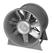
2 Three-Way Heat Saver/Ventilator The Three-Way Heat Saver/Ventilator is a multi-purpose fan designed for ventilating applications that require air recirculation. Winter-time heat saving is its outstanding feature but the patented reversible fan and versatile damper control systems make a unique year-round ventilation device capable of operating in four different modes. The Three-Way Heat Saver/Ventilator can optimize its usefulness by operating in the mode that is most efficient for a given situation. Modes l Supply Air Mode Supplies 100% outside air l Exhaust Mode Exhausts stale or hot air l Heat Saver Mode Recovers warm air from the ceiling and directs it back to the work area l Mixed-Air Mode Mixes outside air with warm in-door air and directs it to the work area Capabilities & Features l Sizes 2" to 60" l Capacities to 62,000 CFM l Pressures to 3/8" SP l Optional construction of Aluminum, Galvanized, 30 and 316 Stainless Steel l Optional 2-way configuration for lower first cost, less maintenance (see page 5) Typical Three-Way Heat Saver Configuration l Hooded inlet l Motor operated recirculating dampers (quantity 2) l Direct drive reversible panel fan l Plenum section l Prefab insulated curb (optional) l Modulated supply damper (optional) to mix outside air with recirculated air l Modulated temperature control (optional) to temper recirculated air with outside fresh air Typical Three-Way Unit in the Heat Saver Configuration The Aerovent Heat Saver/Ventilators shown herein have been tested and rated in accordance with industry-accepted test codes, and are guaranteed by Aerovent to deliver rated performance Aerovent Bulletin illustrations cover the general appearance of Aerovent products at the time of publication and we reserve the right to make changes in design and construction at any time without notice. 2 Aerovent Bulletin 673
3 Three-Way Hooded Heat Saver/Ventilator (Model RREH) Application Buildings with high ceilings save on energy costs by using the Three-Way Heat Saver configuration. During the winter, heated air inside the building rises to the ceiling where it becomes trapped. Air temperatures near the ceiling may be 5 F to 20 F higher than temperatures at the floor in the working area. Due to convection, the heat is transferred to the exterior side of the ceiling. This causes the building to lose heat. To compensate for this heat loss and maintain a uniform temperature, the building s heating system must continually work at maximum levels. By installing the Heat Saver unit, the warmer air at the ceiling is recovered and directed to the working area. As standard, the unit is furnished with recirculating dampers on two sides of the plenum section. The unit recirculates the air by inducing it through the recirculating dampers and directing it back to the floor level. Recirculating the heated air minimizes the transfer of heat through the building s ceiling and reduces the energy load on the building s heating system. By recycling the trapped warm air, a manufacturer can expect to save 10 to 30% on fuel bills. (See the table on page for approximated temperature variations between the floor and various ceiling heights.) In areas where high heat loads occur, the Three-Way Heat Saver/Ventilator can operate in the mixed air mode and mix the recirculated air with outside air to maintain a comfortable working environment. Figure 1. Heat Saver Mode Figure 2. Mixed Air Mode Recirculating dampers open,outside air dampers closed. Modes Heat Saver Mode In the heat saver mode (Figure 1), the unit induces warmer air trapped near the ceiling through the recirculating dampers and directs it downward to the working area. Recirculating the air in this way reduces the load on the heating system by maintaining a nearly uniform temperature between the floor and the ceiling. Mixed Air Mode The optional modulating damper control system (Figure 2) permits outside air to be added to the recirculated air. This is particularly desirable in spring and fall when wide outside temperature fluctuations can cause the heating system to override. Exhaust Mode / Supply Mode With the recirculating dampers closed, the unit can be used to exhaust hot air from the ceiling area (Figure 3). By reversing the fan rotation, 100% outside air can be supplied (configuration not shown). The patented reversible fan moves the same volume of air in both the supply and exhaust directions. The fan s rotation is easily switched between supply and exhaust by using the optional reversing starter. In large rooms, it is particularly effective to use several ventilators for summertime ventilation, using alternating units as supply fans and exhaust fans. Units can then be arranged in this pattern for thorough coverage. Figure 3. Exhaust Mode Recirculating dampers and outside air damper are modulated for proper air control. Recirculating dampers closed, outside air dampers open. Aerovent Bulletin 673 3
4 Three-Way Hooded Heat Saver/Ventilator (Model RREH) Modulating Damper Control An integral part of the Three-Way Heat Saver/Ventilator is Aerovent s Modulating Damper Control package. The Modulating Damper Control package is designed to modulate one supply/exhaust damper, mounted horizontally at the roof curb level, and two recirculating dampers, mounted vertically on two sides of the unit s plenum section. The three fan dampers are modulated to provide the right mix of recirculated air and outside air which reduces the heat load on the building s heating system, lowering the building s energy usage. The Damper Control package modulates the three fan dampers by using a discharge-air temperature-sensor, controlled from a remote set point. The dampers are modulated to maintain the temperature selected on the remote station. Modulating the dampers provides the right mix of recirculated air and outside air for supply, exhaust and recirculating operations. The control station is furnished as a separate part for remote mounting at the site. It houses the reversing starter switch for starting the fan and changing direction (reversing motor starter optional), and a temperature set point for temperature adjustments between 0 and 90 F. A mounting bracket for the discharge sensor is included for field installation at the plenum discharge. (See page 7 for the wiring diagrams, details of the control package, and adjustment and test procedures.) Construction and Finish Three-Way Heat Saver units are manufactured from 12-gauge continuous welded steel. Units are finished with air-dry alkyd gray enamel. Each unit is constructed with close tolerances between the propeller tips and the orifice to maintain maximum efficiency. The patented reversible, cast aluminum alloy propeller is secured to the motor shaft with a split taper lock bushing. The hood of the Three-Way Heat Saver/Ventilator is constructed of corrosion resistant fiberglass reinforced polyester and is attached to the fan with heavy-duty structural angle supports for added stability. Installation Three-Way Heat Saver/Ventilator units are designed for easy installation. The fan/damper section slides down through the roof opening until the flange at the top of the section rests on the roof curb. When a bolt-on flange is requested, the unit can be installed from under the roof. The fan/damper section slides up through the roof opening. The flange is then bolted to the top of this section to rest on the roof curb. The hooded section or stack cap is mounted on top of the roof curb. Extensions of the fan/damper section are available to insure clearance of the roof and structural ceiling supports. Design Considerations When applying a recirculating device such as the Three- Way or Two-Way Heat Saver/Ventilator, the installer should keep in mind terminal velocities for human comfort at floor levels. The recommended velocities for continuous exposure at work stations are: l Sitting ft/min. l Standing ft/min. On buildings with low ceilings (20 to 30 ft. high), the installer should consider using an air distributor for maximum employee comfort. Buildings with 0 to 50 ft. high ceilings can discharge downward through directional discharge grilles. Relationship of Ceiling Height to Temp. Variance ROOF ELEVATION TEMPERATURE GRADIENT BETWEEN FLOOR AND CEILING 0 FT. 12 TO 20ºF 30 FT. 8º TO 12ºF 20 FT. 5º TO 8ºF Aerovent Bulletin 673
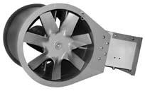
5 Two-Way Heat Saver/Ventilator with Stack Cap (Model RRES) A Two-Way Heat Saver unit is recommended when not all of the features of the Three-Way unit are required. The Two-Way Heat Saver unit has a lower first cost than the Three-Way design. It uses automatic (gravity) dampers rather than motor driven dampers, which have a lower first cost and require less maintenance than motorized dampers. Figure. Exhaust Mode Application Exhaust Mode In the exhaust mode (Figure ), the unit exhausts the heated air at the floor and ceiling levels to cool the working area. During summer operation, where the work area is continually hot, a Two-Way Heat Saver/Ventilator is recommended (see Figure ). In this configuration, the unit exhausts the warm ceiling air and the heated air from the floor to maintain a cool and comfortable working environment. Recirculation Mode In the recirculation mode (Figure 5), the unit recirculates warm air trapped near the ceiling and directs it to the floor level to save on heating costs. Construction and Finish Two-Way Heat Saver/Ventilators are manufactured from 12-gauge continuous welded steel. Units are finished with air-dry alkyd gray enamel. Each unit is constructed with close tolerances between the propeller tips and the orifice to maintain maximum efficiency. The patented reversible, cast aluminum alloy fan wheel is secured to the motor shaft with a split taper lock bushing. The Two-Way Heat Saver/Ventilator s rolled steel circular windband cuts down on wind resistance and is easily removable. Flanges are integrally formed for increased strength. Figure 5. Recirculation Mode Aerovent Bulletin 673 5

.")
6 Accessories Disconnect Switch Permits safe servicing of the unit. Designed to ensure isolation of the fan motor from remote starting equipment. Disconnect can be mounted and wired at the factory if the bolt-on flange accessory is also selected. Otherwise, disconnect must ship loose. Bird Screen Prevents foreign material from entering the fan assembly. On hooded units, a wire mesh type bird screen is mounted inside the plenum (not shown). On stack cap units, a spiral wire guard bird screen is bolted on top of the cap (shown below). NEMA 3R Enclosure (rainproof/sleet resistant) Discharge Grille Permits the airflow to be directed in any downward direction and is recommended for buildings with 0 to 50 ft. high ceilings. The discharge grille features two sets of louvers operating in perpendicular directions. By adjusting one or both louvers, the downward airflow can be aimed to a specific location. The discharge grille mounts horizontally to the bottom of the fan/damper section. L Dimension Extension Ensures the clearance of the roof and ceiling support structures. The square duct extension is available in 1-foot increments. Bolt-On Flange Permits the fan/damper section to be installed from inside the building from under the roof. The fan/damper section slides up through the roof opening. The flange is then bolted to the top of the fan/damper section and rests on the roof curb. Air Distributor: -Way Directional Discharge Grille Permits the airflow to be aimed horizontally in four directions and is recommended for buildings with low ceilings (20 to 30 ft.). One bi-directional grille is mounted vertically to each side of the fan/damper section to distribute the air in four directions. Roof Curb NEMA Combination Reversing Starter/ Disconnect With Control Transformer A reversing starter is used for changing the rotation of the motor and propeller. It permits the Three-Way Unit to switch from recirculating to exhaust or supply to exhaust (and vice versa). The combination reversing starter simplifies field installation of the disconnect and starter by providing the two devices in a single enclosure. A separate disconnect switch is recommended above the roof for additional safety. 6 Aerovent Bulletin 673
7 Control Station Control Station & Enclosure The control station consists of a 12-terminal terminal strip, 5-amp fuse, fuseblock, Supply-Off-Exhaust selector switch (reversing switch), remote set point, and nameplate overlay. Components Mounted On Three-Way Heat Saver/Ventilator 1. Motor Operated Center-Pivoted Shutter FAN SHUTTER SIZE SIZE SUPPLY/EXHAUST (QTY. 1) RECIRCULATING (QTY. 2) 2 2 x x x x x x x 32 3 x x x x x x x 3 Dimensions are not to be used for construction. 2. Modulating Shutter Motor: Model M130 Johnson Controls. Torque Rating: 50 in-lb (5.6 n-m) 3. Shutter Motor Crankarm. Electronic Input Board R81QAA 5. 2V Cover Mounted Transformer Checkout Procedure 1. When installation and wiring are complete, make system settings and apply power. 2. Cycle the motor actuator, using the controller, after the linkage and motor actuator have been assembled to the valve or damper. 3. Observe at least three complete operating cycles to be sure that all components are functioning correctly.. The actuator should not be stalled by the damper or valve. 5. The actuator may be damaged if it is not free to complete its full stroke. Repairs and Replacements The drive motor and gear train are immersed in oil and sealed in a die-cast case; therefore, maintenance is not necessary. Field repairs must NOT be made except for replacement of the cover or the R81 electronic board kits (ordered separately). For a replacement cover, motor actuator, or electronic board kit, contact the nearest Johnson Controls Commercial Systems wholesaler. Three-Way Control Package Details Components Not Mounted On Three-Way Heat Saver/Ventilator Remote Control Station Wiring TO MOTOR STARTER 115 VOLT SUPPLY TO DAMPER MOTOR & DISCHARGE SENSOR 1. Discharge Sensor/Mounting Bracket 2. Remote Control Station Three-Way Heat Saver Adjustment Procedure Selector Switch H 1 H FUSE 1. Jumper terminal 8 to Apply 2VAC to terminals T1 and T2. 3. Adjust linkage to FULL CLOSED position on the outside air damper.. Turn power OFF and remove jumper. 5. Jumper 8 to T1. 6. Turn power ON. 7. Allow motor to travel until it stops; then turn travel adjust potentiometer to desired FULL OPEN position. Caution: M130 must not be allowed to stall; turn travel adjust potentiometer if necessary to prevent a stall condition. 8. Turn OFF power and remove jumper. 9. Connect system per wiring diagram. 10. Turn power ON. 11. Adjust the proportional band (blue knob labeled PB adj ) midway between its full clockwise (CW) and full counterclockwise (CCW) rotation. This will give approximately a 15 F PB. If a smaller PB is desired turn CW. If actuator oscillates or hunts turn PB CCW until the system stabilizes. 12. Turn the M130 Set Point (black knob) full CCW. 13. Adjust remote set point (Y5) to desired setting. Remote Setpoint Elementary Wiring Diagram 60V H FUSE OFF SUPPLY EXHAUST Y-5BA ENCLOSURE 8" x 10" L1 R B DISCHARGE SENSOR A91GAA-2 230V 115V * BY OTHERS 10 T V S1 L2 L3 T2 X XD F F F R R R REMOTE SETPOINT Y-5BA-1 T1 T2 T3 SUPPLY FAN STARTER* FSR O.L. FSR EXHAUST FAN STARTER* S2 MOTOR M130QGA-1 R81QAA-1 FAN MOTOR * ELECTRICAL INTERLOCKS NOT FURNISHED ON SIZE 00 STARTERS * Note: Motor Starters are available as an option. Aerovent Bulletin 673 7
8 Dimensional Data Three-Way Heat Saver/Ventilator With Hooded Inlet and Motor Operated Dampers (Model RREH) Note: Sizes 2 to 8 have fiberglass hoods. Sizes 5 & 60 have painted steel hoods. P SQ. G A* J±1/ L* 9-1/2 8-1/2 D SQ. (INSIDE) 6 K EXHAUST AIRFLOW SUPPLY Q DAMPER SQ. EXHAUST BIRD SCREEN (OPT.) PREFAB CURB (OPT.) AIRFLOW MAX. DISTANCE 16" BETWEEN DAMPERS 20" x 25" BOLT-ON ACCESS DOOR DISCONNECT SWITCH (OPT.) 3/ RECIRCULATED AIR WINTER C I.D. B SQ.** 12 GA. DISCHARGE GRILLE (OPT.) * Standard minimum length. Other lengths optional. ** Customer s minimum curb opening should be 1 1 " greater than B sq. on this drawing. 'E' dimension is outside dimension of bolt-on flange. Consult factory for details. Dimensions in inches unless otherwise noted. Dimensions are not to be used for construction. SIZE A B C D E G J K L P Q R2979B/R23659E 8 Aerovent Bulletin 673
9 Dimensional Data Two-Way Heat Saver/Ventilator With Stack Cap and Automatic Recirculation Shutters (Model RRES) G EXHAUST AIR O.D. I.D. SUMMER BIRD SCREEN (OPT.) * Standard minimum length. Other lengths optional. ** Customer s minimum curb opening should be 1 1 " greater than B sq. on this drawing. 'E' dimension is outside dimension of bolt-on flange. Consult factory for details. Dimensions in inches unless otherwise noted. Dimensions are not to be used for construction. *A±1/2 *L J±1/ 9-1/2 8-1/2 AIRFLOW D SQ. (INSIDE) 6 K AIRFLOW PREFAB CURB (OPT.) 20" x 25" BOLT-ON ACCESS DOOR DISCONNECT SWITCH (OPT.) SIZE A B C D E G J K L I.D. O.D / RECIRCULATED AIR WINTER C I.D. B SQ.** 12 GA. DISCHARGE GRILLES (OPT.) R23661E Two-Way Heat Saver/Ventilator With Hooded Inlet and Automatic Recirculation Shutters (Model RRES) P SQ. Note: Sizes 2 to 8 have fiberglass hoods. Sizes 5 & 60 have painted steel hoods. * Standard minimum length. Other lengths optional. ** Customer s minimum curb opening should be 1 1 " greater than B sq. on this drawing. 'E' dimension is outside dimension of bolt-on flange. Consult factory for details. Dimensions in inches unless otherwise noted. Dimensions are not to be used for construction. A* G J±1/ L* 9-1/2 8-1/2 AIRFLOW D SQ. (INSIDE) 6 K EXHAUST Q DAMPER SQ. EXHAUST PREFAB CURB (OPT.) AIRFLOW 20" x 25" BOLT-ON ACCESS DOOR DISCONNECT SWITCH (OPT.) SIZE A B C D E G J K L P Q Aerovent Bulletin 673 R2980B/R23660E 3/ RECIRCULATED AIR WINTER C I.D. B SQ.** 12 GA. DISCHARGE GRILLE (OPT.) 9
10 Performance Data PROP 2R60 2R628 2R63 30R630 30R63 30R60 36R628 36R632 2R63 8R626 8R632 5R626 5R630 5R63 60R632 60R636 60R632 CATALOG NUMBER CUBIC FT. PER MIN. & HORSEPOWER AT STATIC PRESSURE 0" SP 1/8" SP 1/" SP 3/8" SP FAN TYPE* RPM HP CFM BHP CFM BHP CFM BHP CFM BHP RRES / RREH / RRES RREH RRES ½ RREH ½ RRES RREH RRES ½ RREH ½ RRES RREH RRES RREH RRES RREH RRES RREH RRES RREH RRES RREH RRES RREH RRES 870 7½ RREH 870 7½ RRES RREH RRES 690 7½ RREH 690 7½ RRES RREH RRES RREH * RRES - 2-Way Heat Saver/Ventilator RREH - 3-Way Heat Saver/Ventilator 1. Performance shown is for installation Type A: free inlet, free outlet. 2. Performance ratings include the effects of either a hood (RREH) or a stack cap (RRES) in the airstream. 10 Aerovent Bulletin 673
11 Typical Specifications Heat Saver/Ventilators shall be direct drive Models RRES and RREH, as manufactured by Aerovent, Minneapolis, Minnesota, and shall be of the size and capacity as indicated in the fan schedule. Units shall be complete with: M A Hood Assembly (RREH) for Vertical Supply and Discharge M A Stack Cap Damper Assembly (RRES) for Vertical Upblast Discharge Heat Saver/Ventilators shall be tested and certified with industry test codes and guaranteed by the manufacturer to deliver at the rated published performance levels. In addition, each unit shall be factory run tested prior to shipment. CONSTRUCTION The fan/damper section shall be constructed of 12-gauge mild steel and shall be continuously welded. The plenum houses a reversible, direct drive panel fan. The fan shall be constructed of the following optional metals: M Aluminum M Galvanized M Stainless Steel 30 M Stainless Steel 316 PROPELLERS Propellers shall be of cast aluminum alloy with reversible performance characteristics and shall be secured to the motor shaft with a split taper lock bushing on all sizes. Balancing The propeller assembly shall be statically and dynamically balanced in accordance with ANSI/AMCA Balance Quality and Vibration Levels for Fans to Fan Application Category BV-3, Balance Quality Grade G6.3. In addition, direct drive fan propellers shall be balanced on the motor shaft after final assembly in the fan, in the manufacturing facility, to the following peak velocity values, filter-in, at the fan test speed: Fan Application Rigidly Mounted Flexibly Mounted Category (in./s) (in./s) BV MOTORS Fan motors shall be foot mounted NEMA Design B, standard industrial continuous duty, ball bearing, variable torque type and shall be provided with the enclosure type, voltage, phase, and hertz as listed on the fan schedule. FINISH The units, after fabrication, shall be cleaned and chemically pretreated by a phosphatizing process and shall be painted inside and outside with an alkyd primer and finish painted with an air dry enamel. SOUND POWER LEVELS The sound power levels of the fan(s) shall not exceed Octave Band-CPS (Sound Power ) OPTIONAL ACCESSORIES The fans shall be furnished complete with: M NEMA 3R Outdoor Rainproof Disconnect Switch Mounted and Wired (Only for units that also have the bolt-on flange accessory. Shipped loose otherwise.) M Discharge Grilles M Air Distributor: -Way Directional Discharge Grille M Square Flat Guard, Wire Mesh, Mounted in Top of Fan/Damper Section (RREH) M Discharge Birdscreen, Mounted on Top of Stack Cap (RRES) M L Dimension Extension M Bolt-on Flange M NEMA Combination Reversing Starter/Disconnect With Control Transformer IEC Starter or NEMA Starter (Shipped Loose). M Prefabricated Insulated Roof Curb Aerovent Bulletin


")


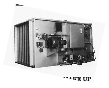
12 Quality Air Handling Equipment AIR HEATER ROOF VENTILATOR CENTRIFUGAL VANEAXIAL AXIAL FLOW Tubeaxial Type VT Industrial Exhaust Upblast Propeller Panel Fan Type W Adjustable Pitch CB / CBA Upblast Axial Mancooler Type VTF Fiberglass Series 1 High Pressure Tu-WAY Ring Fan Type B Higher Pressure Centaxial Fiberglass Tubeaxial Adjustable Pitch Axico Anti-Stall Pressure Blower PRV Centrifugal Gas-Fired Air Make-Up Steam Air Make-Up Door Air Heater WARRANTY Aerovent equipment is guaranteed to deliver its rated output, if properly installed and operated under normal conditions. Aerovent will correct by repair, replacement, or issuance of credit at our option, F.O.B. our plant, defects in material or workmanship which may develop under normal and proper use within eighteen (18) months after date of shipment from our factory, if purchaser gives us notice within ten (10) days of discovering such defects. The correction of these defects by repair, replacement, or issuance of credit shall constitute fulfillment of all obligation to purchaser. (NOTE: We will not assume expense or liability for repairs made outside our factory without prior written consent.) 1.5MPP12/09 TM
Turning Air Into Solutions. TUBEAXIAL PAINT SPRAY BOOTH EXHAUST FANS. Model TCBS
 Turning Air Into Solutions. TUBEAXIAL PAINT SPRAY BOOTH EXHAUST S Model TCBS CATALOG AX220 May 2013 TubeaxialFans Model TCBS The Twin City Fan & Blower model TCBS is a belt driven tubeaxial fan that is
Twin City Fan & Blower
 Twin City Fan & Blower BULLETIN AX010 November 2005 AXIAL POWER ROOF VENTILATORS Power Roof Ventilators Twin City Fan & Blower offers a wide variety of Power Roof Ventilators (PRVs). The PRVs have been
Modular Supply Make-Up Air Unit
 Modular Supply Make-Up Air Unit Model MSX Flexible Design Factory Assembled Heating Options Hot Water Steam Electric Cooling Options Evaporative Direct Expansion Chilled Water November 2009 Product Features
A. General: Refer to paragraph entitled "SUBMITTAL" in Section Include the following data:
 SECTION 15860 - FANS PART 1 - GENERAL 1.01 RELATED DOCUMENT A. Basic Requirements: Provisions of Section 15010, BASIC MECHANICAL REQUIREMENTS, and Section 15030, ELECTRICAL REQUIREMENTS FOR MECHANICAL
Construction Standards Page Exclusively published and distributed by Architectural Computer Services, Inc. (ARCOM) for the AIA
 for the AIA") Construction Standards Page 233423-1 Copyright 2009 by The American Institute of Architects (AIA) Exclusively published and distributed by Architectural Computer Services, Inc. (ARCOM) for the AIA Modified
Construction Standards Page 233423-1 Copyright 2009 by The American Institute of Architects (AIA) Exclusively published and distributed by Architectural Computer Services, Inc. (ARCOM) for the AIA Modified
Indirect Gas-Fired Make-Up Air
 Indirect Gas-Fired Make-Up Air Model IG 800 to 7,000 cfm Up to 400,000 Btu/hr Multiple Furnace Control Options Optional Evaporative Cooling May 20041 Product Features Model IG Indirect Gas-Fired Make-Up
DENVER PUBLIC SCHOOLS DESIGN AND CONSTRUCTION STANDARDS This Standard is for guidance only. SECTION EXHAUST FANS
 PART 0 A/E INSTRUCTIONS 0.01 DESIGN REQUIREMENTS A. Placement within a mechanical room is required for all major mechanical equipment. Only small units may be roof-mounted, and shall be made as inconspicuous
Direct Gas-Fired Make-Up Air
 Direct Gas-Fired Make-Up Air Model TSU Heavy Duty, High Airflow Applications Manufacturing and Industrial Facilities Up to 64,000 cfm August 2012 Products Model TSU Direct Gas-Fired Make-Up Air Unit The
Industrial Space Heating Direct Gas-Fired Heating. Greenheat 50/50 Recirculation
 Industrial Space Heating Direct Gas-Fired Heating Greenheat 00% Outdoor Air Greenheat 50/50 Recirculation 80/0 Recirculation March 008 Product Overview Industrial Space Heating Greenheck s space heating
High Plume Blowers Suggested Specification Section (Master Format 1996) Suggested Specification Section (Master Format 2004)
 Suggested Specification Section (Master Format 2004)") High Plume Blowers Suggested Specification Section 15500 (Master Format 1996) Suggested Specification Section 23 38 16 (Master Format 2004) PART 1 GENERAL 1.01 WORK INCLUDED High Plume Laboratory Exhaust
High Plume Blowers Suggested Specification Section 15500 (Master Format 1996) Suggested Specification Section 23 38 16 (Master Format 2004) PART 1 GENERAL 1.01 WORK INCLUDED High Plume Laboratory Exhaust
Direct Fired Heater Model AD Specification
 Direct Fired Heater Model AD Specification Description A Direct-fired gas heating and ventilating unit(s), as indicated on the drawings shall be furnished. Unit(s) shall be tested in accordance with ANSI
AXICO ANTI-STALL CONTROLLABLE PITCH-IN-MOTION AND ADJUSTABLE PITCH-AT-REST VANEAXIAL FANS
 Twin City Fan INDUSTRIAL PROCESS AND COMMERCIAL VENTILATION SYSTEMS AXICO ANTI-STALL CONTROLLABLE PITCH-IN-MOTION AND ADJUSTABLE PITCH-AT-REST VANEAXIAL FANS FPAC FPMC FPDA CATALOG AX351 JULY 2001 WWW.TCF.COM
Twin City Fan & Blower
 Twin City Fan & Blower BULLETIN AX351 July 2001 AXICO ANTI-STALL Controllable Pitch-In-Motion and Adjustable Pitch-At-Rest Vaneaxial Fans Types FPAC, FPMC, FPDA A complete product bulletin including performance
Internal ridged board 1" x 1.5 foil face installation shall be installed on roof, walls and base of casing.
 A-D WITH MPU SPECIFICATION WRITTEN SPECIFICATION Description A Modular Packaged Heating, Cooling and ventilating unit(s), as indicated on the drawings shall be furnished. Direct Fired Gas Unit(s) shall
Brown University Revised August 3, 2012 Facilities Design & Construction Standards SECTION AIR HANDLING UNITS
 SECTION 23 70 00 AIR HANDLING UNITS PART 1. GENERAL 1.1 Section includes air-handling units to 15,000 cfm and accessories. 1.2 Related Sections 1 : A. Division 01 - Brown University Standard for Narragansett
A. Codes and Standards that are Standard at the University:
 PART 1: GENERAL 1.01 Purpose: 1.02 References: 1.03 Requirements: A. This standard is intended to provide useful information to the Professional Service Provider (PSP) to establish a basis of design. The
BULLETIN G-99. March 2005 CONDENSED CATALOG. Air Moving Products
 BULLETIN G-99 March 2005 CONDENSED CATALOG Air Moving Products Aerovent History Over 75 Years of Growth A brief history of Aerovent includes: the first Aerovent fan manufactured in 1926 by Piqua Electric
FAS Fresh Air Supply Units
 TGFAS-2 FAS Fresh Air Supply Units TECHNICAL GUIDE STEAM AND HOT WATER MAKE-UP AIR HEATERS WITH INTEGRAL FACE AND BYPASS COILS FOR EFFECTIVE TEMPERATURE CONTROL Since 1875, the L.J. Wing Company has been
UNIVERSITY SERVICES ANNEX James Madison University Harrisonburg, Virginia State Project Code: Architect s Project Number:
 SECTION 233423 - HVAC POWER VENTILATORS PART 1 - GENERAL 1.1 RELATED DOCUMENTS A. Provisions of the Contract and of the Contract Documents apply to this Section. 1.2 PERFORMANCE REQUIREMENTS A. Operating
UNIVERSITY OF ROCHESTER DESIGN STANDARDS NOVEMBER 1, 2013
 SECTION 15800 - AIR HANDLING EQUIPMENT 1.1 GENERAL A. All air handlers installed shall conform to the University of Rochester specification Guideline for Semi-Custom and Pre-Engineered Air Handling Units.
Modular Heating & Ventilating Unit Model IGX-HV
 Modular Heating & Ventilating Unit Model IGX-HV Indirect Gas-Fired Heating Evaporative Chilled Water DX Cooling October 2008 Product Features Model IGX-HV Indirect Gas-Fired Heating and Ventilating Unit
HARTZELL. Tempered Air Heating Equipment. Hartzell Fan, Inc., Piqua, Ohio
 Tempered Air Heating Equipment Series GFR GMC GMP SAH SCH SFC SMC SMP 77 78H 78V 79 811 Hartzell Fan, Inc., Piqua, Ohio 45356 January 2011 Index Hartzell Model Code Explanation..................... Page
Selecting the Correct Fan
 Selecting the Correct Fan Ryan B. Johnson Air Purification Company Sales Engineer Member, ASHRAE Pikes Peak Chapter rjohnson@airpurificationcompany.com 1 Your Speaker circa 1998 Fan Types Applications
AMERICAN COOLAIR CORPORATION. Greenhouse Ventilation Systems. Farm Products Division
 AMERICAN COOLAIR CORPORATION Greenhouse Ventilation Systems Farm Products Division AL Aluminum Greenhouse Fan American Coolair s AL all-aluminum fans are the answer to concerns about rust and corrosion
KIC Air Curtains. Technical Guide
 TGKIC-3 KIC Air Curtains Technical Guide AIR PERFORMANCE AIR MOVEMENT AND CONTROL ASSOCIATION INTERNATIONAL, INC. King certifies that the air curtains shown herein are licensed to bear the AMCA seal. The
SECTION (15833) - HVAC POWER VENTILATORS
 - HVAC POWER VENTILATORS") PART 1 GENERAL 1.01 SUMMARY SECTION 23 34 23 (15833) - HVAC POWER VENTILATORS A. Section Includes: 1. Centrifugal Roof Ventilators. 2. Up-blast Roof Exhaust Fans (Kitchen Hood Exhaust). 3. Ceiling-Mounted
PART 1 GENERAL 1.01 SUMMARY SECTION 23 34 23 (15833) - HVAC POWER VENTILATORS A. Section Includes: 1. Centrifugal Roof Ventilators. 2. Up-blast Roof Exhaust Fans (Kitchen Hood Exhaust). 3. Ceiling-Mounted
Schust Engineering, Inc. 701 North Street P.O. Box 128 Auburn, IN (260) Fax: (260)
 Fax: (260)") Schust Engineering, Inc. 701 North Street P.O. Box 128 Auburn, IN 46706 (260) 925-6550 Fax: (260) 925-6093 Industrial Facility Midwest Re: Facility Ventilation Audit Schust Engineering, Inc. is pleased
Schust Engineering, Inc. 701 North Street P.O. Box 128 Auburn, IN 46706 (260) 925-6550 Fax: (260) 925-6093 Industrial Facility Midwest Re: Facility Ventilation Audit Schust Engineering, Inc. is pleased
SPECIFICATION DELETED SECTION CENTRIFUGAL HVAC FANS
 SECTION 23 34 16 CENTRIFUGAL HVAC FANS PART 1 - GENERAL 1.01 RELATED DOCUMENT A. Drawings and general provisions of the contract, including General and Special Conditions and Division 01 Specification
GA Gas Unit Heater Assemblies Technical Guide
 TGGA-2 GA Gas Unit Heater Assemblies Technical Guide INDIRECT-FIRED GAS HEATING ASSEMBLIES FOR LARGE OPEN SPACES AND DOOR HEATING APPLICATIONS S ince 7, the L.J. Wing Company has been a leader in providing
University of Houston Master Construction Specifications Insert Project Name
 University of Houston Master Construction Specifications Insert Project Name SECTION 23 82 20 - FANS, AIR INTAKES AND RELIEF VENTS PART 1 - GENERAL 1.1 RELATED DOCUMENTS: A. The Conditions of the Contract
SPLIT-SYSTEM EVAPORATOR BLOWER DESCRIPTION FEATURES L4EU NOMINAL TONS
 036-21096-001 (0101) SPLIT-SYSTEM EVAPORATOR BLOWER L4EU240 20 NOMINAL TONS DESCRIPTION This 20 ton evaporator blower is designed with two distinct modules to provide maximum application flexibility. The
Bulletin FH05 FUME EXHAUST
 Bulletin FH05 FUME EXHAUST Models: FH, FHL Curb Mounted Centrifugal Fans Fume Exhaust Systems - FH/FHL Introduction The PennBarry FH fans are designed to meet the various requirements for fume exhaust
Propeller Fans. Industrial And Commercial Fans Belt And Direct Drive. Your Clean Air Source!
 Propeller Fans Industrial And Commercial Fans Belt And Direct Drive Your Clean Air Source! MODEL PVL EXHAUST FANS Application Economical fans for use in kitchens, laundries, taverns, bakeries and also
K*ES120 DESCRIPTION TECHNICAL GUIDE SPLIT-SYSTEM EVAPORATOR BLOWERS 10 NOMINAL TONS EER 8.5 ACCESSORIES FIELD INSTALLED TABLE 1: ARI RATINGS*
 TECHNICAL GUIDE SPLIT-SYSTEM EVAPORATOR BLOWERS K*ES120 10 NOMINAL TONS EER 8.5 DESCRIPTION These completely assembled dual circuit evaporator blower units include a well-insulated cabinet, a DX cooling
SECTION AXIAL FANS
 PART 1 - GENERAL 1.1 RELATED DOCUMENTS A. Drawings and general provisions of the Contract, including General and Supplementary Conditions and Specification Sections, apply to this Section. B. Related Sections:
Plenum Fans. Model HPA. Direct Drive
 Plenum Fans Model HPA Direct Drive October 2012 Quiet & Efficient HPA Plenum Fans Greenheck s modular plenum fan, model HPA, is designed and engineered to provide superior performance and reliability in
Evase Vaneaxial Fans 500mm to 1400mm Diameter Bulletin ECA 10-07
 www.howden.com Evase Vaneaxial Fans 500mm to 1400mm Diameter Bulletin ECA 10-07 Evase Vaneaxial fans by Howden can save energy over the installed life of the system by recovering the kinetic energy contained
KINGS COUNTY JAIL EXPANSION PHASE III COUNTY OF KINGS SECTION
 SECTION 237433, PART 1 - GENERAL 1.1 RELATED DOCUMENTS A. Drawings and general provisions of the Contract, including General and Supplementary Conditions and Division 01 Specification Sections, apply to
we make air move Double Inlet Centrifugal Fans (Forward Curved) FBD Series (Square Outlet Metric Size)
 FBD Series (Square Outlet Metric Size)") we make air move Double Inlet Centrifugal Fans (Forward Curved) FBD Series (Square Outlet Metric Size) www.blowtech.in we make air move Blowtech Air Devices Pvt. Ltd. was founded in 1988 and quickly established
we make air move Double Inlet Centrifugal Fans (Forward Curved) FBD Series (Square Outlet Metric Size) www.blowtech.in we make air move Blowtech Air Devices Pvt. Ltd. was founded in 1988 and quickly established
SECTION AIR HANDLING UNIT
 SECTION 15800 - AIR HANDLING UNIT PART 1 - GENERAL 1.01 RELATED DOCUMENTS A. Basic Requirements: Provisions of Section 15010, BASIC MECHANICAL REQUIREMENTS, and Section 15030, ELECTRICAL REQUIREMENTS FOR
Contents INDEX. TDM Series Indirect Fired Heaters
 Contents Typical Indoor Installations................... 000 Indoor Unit Dimensions (Vertical).............. 000 Indoor Unit Dimensions (Horizontal)............ 000 Outdoor Unit Dimensions.....................
Product Specifications. Vertical Floor Consoles By First Co.
 NOW WITH 18 GAUGE CABINET AND FACTORY INSTALLED SERVICE SWITCH Product Specifications VFB Series VSB Series VCB Series Vertical Console Fan Coils 300-00 CFM Vertical Floor Consoles By First Co. VFB Series
TECHNICAL GUIDE SPLIT-SYSTEM AIR-COOLED EVAPORATOR BLOWER 25, 30, 40 & 50 TON LA300, LB360, 480 & 600 (50 Hz) PROVEN PERFORMANCE GENERAL FEATURING
 PROVEN PERFORMANCE GENERAL FEATURING") TECHNICAL GUIDE SPLIT-SYSTEM AIR-COOLED EVAPORATOR BLOWER 25, 30, 40 & 50 TON LA300, LB360, 480 & 600 (50 Hz) PROVEN PERFORMANCE GENERAL The LA/LB line is a flexible performer. LA300, LB360 & 480 can be
TECHNICAL GUIDE SPLIT-SYSTEM AIR-COOLED EVAPORATOR BLOWER 25, 30, 40 & 50 TON LA300, LB360, 480 & 600 (50 Hz) PROVEN PERFORMANCE GENERAL The LA/LB line is a flexible performer. LA300, LB360 & 480 can be
DSV Model Air Cooled Self Contained Indoor Packaged Units 3-5 Tons Preliminary Application Data
 DSV Model Air Cooled Self Contained Indoor Packaged Units 3-5 Tons Preliminary Application Data July 28, 2008 Page 1 1 of 3 PROJECT: TAG: Gross Cooling Capacity [Btuh]: 37,800* Design CFM: 1,200 Seasonal
Energy Guide. Fan Efficiency Grades. FEG Ratings. July
 Energy Guide Fan Efficiency Grades s July 2013 Certified Fans Location Mounting Airflow Application Drive Type Impeller Type Performance Model Outdoor Indoor Roof Curb Base/Floor Hanging Wall Ceiling Mounted
Technical Guide DESCRIPTION CHAMPION SPLIT-SYSTEM EVAPORATOR BLOWER L4EU240A 20 NOMINAL TONS (WORLD 50 HZ) FEATURES XTG-A-0307
 FEATURES XTG-A-0307") DESCRIPTION Technical Guide CHAMPION SPLIT-SYSTEM EVAPORATOR BLOWER L4EU240A 20 NOMINAL TONS (WORLD 50 HZ) This 20 ton evaporator blower is designed with two distinct modules to provide maximum application
DESCRIPTION Technical Guide CHAMPION SPLIT-SYSTEM EVAPORATOR BLOWER L4EU240A 20 NOMINAL TONS (WORLD 50 HZ) This 20 ton evaporator blower is designed with two distinct modules to provide maximum application
SPLIT-SYSTEM EVAPORATOR BLOWERS K2EU060, K4EU090, K3EU120 & K1EU180 5 Thru 15 Nominal Tons DESCRIPTION ACCESSORIES FIELD INSTALLED
 (491) SPLIT-SYSTEM EVAPORATOR BLOWERS K2EU060, K4EU, K3EU & K1EU180 5 Thru 15 Nominal Tons DESCRIPTION These completely assembled units include a well-insulated cabinet, a DX cooling coil with copper tubes
ENGINEERING LETTER 4
 ENGINEERING LETTER 4 The New York Blower Company 7660 Quincy Street, Willowbrook, Illinois 60521-5530 TEMPERATURE AND ALTITUDE AFFECT FAN SELECTION INTRODUCTION Fan performance changes with the density
HVAC REPAIR/REPLACEMENT 07/18/12 SECTION HVAC - MAJOR EQUIPMENT
 SECTION 15300 - HVAC - MAJOR EQUIPMENT PART 1 - GENERAL 1.1 MECHANICAL GENERAL A. Section 15010 is applicable. PART 2 - PRODUCTS 2.1 FANS A. General: 1. All fans shall bear the AMCA Certified Performance
AIR HANDLING UNITS Vibration Isolation Air Filtration Equipment Ductwork.
 SECTION 15855 AIR HANDLING UNITS PART 1 GENERAL 1.01 SUMMARY A. Related Sections: 1. 15240 - Vibration Isolation. 2. 15885 - Air Filtration Equipment. 3. 15890 - Ductwork. 1.02 REFERENCES A. Air Moving
TGIF-1. Indirect Fired Heating Systems. Technical Guide for: IF Indoor Installations. IFW Outdoor Installations. Applied Air. Keeps You.
 TGIF- Indirect Fired Heating Systems Technical Guide for: IF Indoor Installations IFW Outdoor Installations Applied Air Keeps You Warm Indirect Fired Heating Systems Technical Guide In the business of
Introduction to Fans. The Basics of Fan Principles and Terminology
 Introduction to Fans The Basics of Fan Principles and Terminology Airflow Principles A fan is a rotating device that creates pressure differential that results in air movement Pressure rise in a fan Downstream
MHNCCX DX with Hot Water Heat Ceiling Concealed 4-Pipe Heat / Cool Fan Coil 12,000-36,000 BTUH
 MHNCCX DX with Hot Water Heat Ceiling Concealed 4-Pipe Heat / Cool Fan Coil 12,000-36,000 BTUH 318 MHNCCX NOMENCLATURE BREAKDOWN 4-Pipe Heat/Cool Ceiling Concealed Fan Coil MHNCCW- XX - XX Ceiling Concealed
Title: YALE OFFICE OF FACILITIES PROCEDURE MANUAL Chapter: 01 - Yale Design Standard Division: HVAC Standards
 Date Description of Change Pages / Sections Modified ID 6/15/16 Entire document - mgl44 PART 1 - INTRODUCTION 1.1 PURPOSE A. This section is intended to define the general installation and minimum product
Guide Spec Summary. Option List. Date: 05/21/2001. EarthWise Modular Climate Changer Full Spec. Prepared by: Phone Number: Prepared for:
 Date: 05/21/2001 Time: 08:50:16 AM Job Name: EarthWise Modular Climate Changer Full Spec Location: Any Town, Earth Prepared by: Phone Number: Prepared for: Guide Spec Summary Option List SUBMITTALS Submittals
CEILING FANS THE PREMIUM QUALITY LINE FROM COMMERCIAL/INDUSTRIAL & SPECIAL APPLICATION. World Leader in Ceiling Fan Systems
 THE PREMIUM QUALITY LINE FROM COMMERCIAL/INDUSTRIAL & SPECIAL APPLICATION CEILING FANS World Leader in Ceiling Fan Systems Visit our website at: www.marleymep.com Only Leading Edge Offers These Exclusive
Guide Spec Summary. Option List. Date: 05/21/2001. EarthWise VAV Terminal Units Full Spec. Prepared by: Phone Number: Prepared for:
 Date: 05/21/2001 Time: 02:57:44 PM Job Name: EarthWise VAV Terminal Units Full Spec Location: AnyTown, Earth Prepared by: Phone Number: Prepared for: Guide Spec Summary Option List SINGLE & DUAL DUCT UNIT
A. American National Standards Institute (ANSI): Establishes requirements applicable to certifying direct gas-fired heaters.
: Establishes requirements applicable to certifying direct gas-fired heaters.") SECTION 15622 DIRECT GAS-FIRED BURNER & MANIFOLD SYSTEM PART 1: GENERAL 1.1 Section includes: A. Direct gas-fired heater modules B. Controls C. Equipment schedule 1.2 Related Sections A. Section 01655:
SECTION 15622 DIRECT GAS-FIRED BURNER & MANIFOLD SYSTEM PART 1: GENERAL 1.1 Section includes: A. Direct gas-fired heater modules B. Controls C. Equipment schedule 1.2 Related Sections A. Section 01655:
Technical Guide DESCRIPTION ACCESSORIES FIELD INSTALLED SPLIT-SYSTEM EVAPORATOR BLOWERS. 7-1/2 and 10 NOMINAL TONS LA090 & LA120 SUPPLY AIR PLENUMS
 Technical Guide SPLIT-SYSTEM EVAPORATOR BLOWERS 7-1/2 and 10 NOMINAL TONS LA090 & LA120 DESCRIPTION These completely assembled units include a well-insulated cabinet, a DX cooling coil with copper tubes
Catalog Destiny Indoor Air Handler. Models Horizontal Configuration. Vertical Configuration
 Destiny Indoor Air Handler Models 002 030 Catalog 580-8 Horizontal Configuration Vertical Configuration Table of Contents Introduction.... 2 Certification...2 Smoke Control and Management Systems...2 Features
CHAMPION SPLIT-SYSTEM EVAPORATOR BLOWER DESCRIPTION FEATURES L2EU NOMINAL TONS
 550.23-TG5Y (893) CHAMPION SPLIT-SYSTEM EVAPORATOR BLOWER L2EU240 20 NOMINAL TONS DESCRIPTION This 20 ton evaporator blower is designed with two distinct modules to provide maximum application flexibility.
Make-Up Air March 2012
 Make-Up Air March 2012 Comfortable energy efficient kitchen ventilation starts here. At Larkin Industries, our goal is to manufacture well-designed kitchen ventilation systems with environmentally sustainable
A. American National Standards Institute (ANSI) : Establishes requirements applicable to certifying direct gas-fired heaters.
 : Establishes requirements applicable to certifying direct gas-fired heaters.") Section 15 _ Energy Recovery Air Handling System Part 1: GENERAL 1.1 Section Includes: A. Energy Recovery Air Handler B. Controls (most by Others) C. Equipment Schedule 1.2 Related Sections: A. Section
Section 15 _ Energy Recovery Air Handling System Part 1: GENERAL 1.1 Section Includes: A. Energy Recovery Air Handler B. Controls (most by Others) C. Equipment Schedule 1.2 Related Sections: A. Section
Ducted Propeller. Airflow Volume
 Total Pressure Radial-Blade Centrifugal Tubeaxial Backward-inclined Airfoil Centrifugal Forward-curved Centrifugal Ducted Propeller Airflow Volume Figure 2: Forward-Curved Centrifugal Fan
Advance Release September 2009
 Vertical Air Cooled DSV Series R 410A Model DSV096 DSV120 DSV144 DSV180 Nominal Cooling (Tons) 8 10 12 15 Refrigerant R 410A R 410A R 410A R 410A Cooling Performance Gross Cooling Capacity(Btu/h) 95,000*
CAR-MON DUST COLLECTORS SERIES 207, 2410, 3015
 INSTALLATION-OPERATION-MAINTENANCE CAR-MON DUST COLLECTORS SERIES 207, 2410, 3015 TEFC 3 phase motor Outlet duct Fan wheel housing Inlet duct connection After filter transition Optional after filter unit
Industrial Fans & Blowers
 Industrial Fans & Blowers IN-LINE FANS ADD DIRECT DRIVE TUBEAXIAL FANS FEATURES & BENEFITS Spark resistant, cast aluminum airfoil axial impeller Aerodynamically efficient performance Factory set adjustable
SAS Steadyair Make-Up Air Units Technical Guide
 TGSAS-3 SAS Steadyair Make-Up Air Units Technical Guide A COMPLETE AIR TEMPERING PACKAGE FOR COMMERCIAL, INSTITUTIONAL, AND INDUSTRIAL APPLICATIONS S ince 1875, the L.J. Wing Company has been a leader
Hood Depot Internatioonal, Inc., Phone S. Powerline Road, Deerfield Beach, FL
 The Kitchen Cool by Hood Depot is a conditioned make up air unit design with flexibility, form and function kept in mind. Our unit offers a variety of configurations that allow the customer to customize
UNIVERSITY OF MISSOURI Central Station Air-Handling Units March
 GENERAL: 1. This section provides criteria for the design and installation of air handling units. DESIGN GUIDELINES: Design General 1. Location 1.1. For new construction, and existing buildings where possible,
TECHNICAL GUIDE. Description SPLIT-SYSTEM AIR-COOLED CONDENSING UNITS YD360, 480 & THRU 50 NOMINAL TONS YTG-B-0811
 Description These units are completely assembled, piped and wired at the factory to provide one-piece shipment and rigging. Each unit is pressurized with a holding charge of Refrigerant R-410A for storage
SECTION CONVECTION HEATING AND COOLING UNITS
 PART 1 GENERAL 1.01 SECTION INCLUDES A. Baseboard radiation. B. Finned tube radiation. C. Convectors. D. Unit heaters. E. Cabinet unit heaters. F. Fan-coil units. G. Unit ventilators. H. Blower-coil units.
Glossary of Terms Laboratory & Fume Exhaust Fans
 Glossary of Terms Laboratory & Fume Exhaust Fans ACTUATOR, 2-POSITION SPRING RETURN A spring return actuator generally used to control the isolation dampers below the fans. This actuator allows for fully
MXI Mixed Flow Inline Fan
 MXI Mixed Flow Inline Fan PRODUCT GUIDE PennBarry Your Single Source for Commercial & Industrial Supply & Exhaust Fans www.pennbarry.com TABLE OF CONTENTS INTRODUCTION 3 CERTIFICATIONS & LISTINGS 4 MIXED
VentZone Systems VentZone Zoned IAQ with Heat Recovery Kits
 RESIDENTIAL SYSTEM SOLUTIONS VentZone Systems VentZone Zoned IAQ with Heat Recovery Kits VentZone Zoned IAQ Kits with Heat Recovery combine a Standard Residential Heat Recovery Ventilator (HRV) with residential
Technical Guide SUNLINE 2000 DESCRIPTION ACCESSORIES FIELD INSTALLED SPLIT-SYSTEM EVAPORATOR BLOWER K4EU NOMINAL TONS (WORLD 50 HZ)
") Technical Guide SUNLINE 2000 SPLIT-SYSTEM EVAPORATOR BLOWER K4EU180 15 NOMINAL TONS (WORLD 50 HZ) DESCRIPTION These completely assembled units include a well-insulated cabinet, a DX cooling coil with copper
Technical Guide SUNLINE 2000 SPLIT-SYSTEM EVAPORATOR BLOWER K4EU180 15 NOMINAL TONS (WORLD 50 HZ) DESCRIPTION These completely assembled units include a well-insulated cabinet, a DX cooling coil with copper
Cabinet Unit Heaters Steam / Hot Water
 11-160.4 February, 2005 Cabinet Unit Heaters Steam / Hot Water Model C MODEL IDENTIFICATION Table of Contents I. Model Identification... 3 Page Il. IIl. III. IV. Design Benefits A. Features and Benefits...
Warm. IFR Indirect Fired Gas Heating Systems. Applied Air. Keeps You
 TGIFR IFR Indirect Fired Gas Heating Systems Technical Guide for: Outdoor Rooftop Mounted Units To 46,000 CFM And 4,000 MBH Output Applied Air Keeps You Warm Indirect Fired Heating Systems Technical Guide
Fans: Features and Analysis
 Technical Development Program COMMERCIAL HVAC EQUIPMENT Fans: Features and Analysis PRESENTED BY: Michael Ho Version 1.2 Menu Section 1 Section 2 Section 3 Section 4 Section 5 Section 6 Section 7 Section
SSL & SBS Engineering Guide
 REDUCED-FOOTPRINT VERTICAL BLOWER COIL UNITS SSL & SBS Engineering Guide SO TOUGH, WE GUARANTEE IT. SSL SBS Table of Contents Features and Benefits... 3 Construction Features... 4 Features and Options...
A. Section includes Factory Packaged, Modular units, providing cooling and heating for air distribution systems.
 15855 AIR HANDLING UNITS SPECIFIER: CSI MasterFormat 2004 number: 237313 PART 1 GENERAL 1.1 SUMMARY A. Section includes Factory Packaged, Modular units, providing cooling and heating for air distribution
MIN. CCT. QTY RLA LRA HP FLA AMPACITY /1/ /3/
 1 of 3 Cooling Capacity [Btuh] 24,800 * Condensing Unit SEER: 13.0 ** Condensing Unit CFM: 1,600 Condenser Fan No./Type: 1/CENTRIFUGAL Diameter x Width [in]: 10x10 Drive: Adjustable Belt Motor HP: 0.5
McQuay Suite Type N Top Mounted Hydronic Heat Incremental Packaged Terminal Air Conditioners C:
 McQuay Suite Type N Top Mounted Hydronic Heat Incremental Packaged Terminal Air Conditioners C: 1355-4 Page 2 / Catalog 1355-4 (Rev. 5/99) The McQuay Suite II Incremental packaged terminal air conditioners
CLIMATAIR PENTHOUSE AIR HANDLING SYSTEMS
 7 Rosemex Products 97 VENTILATION CLIMATAIR PENTHOUSE AIR HANDLING SYSTEMS 2 INTRODUCTION Rosemex "Penthouse" units are essentially outdoor mechanical rooms. They group in one compact weather proof outdoor
JCseries EVAPORATIVE CONDENSER. engineering data
 JCseries EVAPORATIVE CONDENSER engineering data Recold JC Series Evaporative Condenser Contents 2 Construction... 3 Schematic... 4 Engineering Data... 5 Selection Procedure... 6-9 Multi-Circuited Selection
ISOLATED DIRECT DRIVE PLENUM FAN (IDDP)
") Our Expertise, Your Air-Moving Solution ISOLATED DIRECT DRIVE PLENUM FAN (IDDP) PART# 0601710001_rev_A INSTALLATION, OPERATION & MAINTENANCE MANUAL Please read and save these instructions for future reference.
Our Expertise, Your Air-Moving Solution ISOLATED DIRECT DRIVE PLENUM FAN (IDDP) PART# 0601710001_rev_A INSTALLATION, OPERATION & MAINTENANCE MANUAL Please read and save these instructions for future reference.
AGRI-AIDE Ventilation Equipment. AGRI-AIDE Ventilation Key to Unlocking...
 AGRI-AIDE Ventilation Equipment AGRI-AIDE Ventilation Key to Unlocking... Osborne s world class ventilation equipment keeps indoor environments fresh and healthy for animals and the people who care for
INSTRUMENTATION AND CONTROL DEVICES FOR HVAC
 PART 1 GENERAL 1.01 RELATED REQUIREMENTS SECTION 23 0913 INSTRUMENTATION AND CONTROL DEVICES FOR HVAC A. Section 26 2717 - Equipment Wiring: Electrical characteristics and wiring connections. 1.02 ADMINISTRATIVE
VentZone Systems VentZone Zoned IAQ with Energy Recovery Kits
 RESIDENTIAL SYSTEM SOLUTIONS VentZone Systems VentZone Zoned IAQ with Energy Recovery Kits VentZone Zoned IAQ Kits with Energy Recovery combine a Standard Residential Energy Recovery Ventilator (ERV) with
Chilled Water DOAS Fan Powered Terminal Units
 Chilled Water DOAS Fan Powered Terminal Units CHILLED WATER DOAS FAN POWERED TERMINAL UNITS DOAS TERMINAL UNITS FEATURES AND BENEFITS MINIMUM VENTILATION CONTROL The DOAS unit provides the Designer, Owner
Breezex (BX) Heavy Duty Reversible Supply/Exhaust Fans with Reversing Switch. IMPORTANT! Read before proceeding! OPERATION & MAINTENANCE MANUAL
 Heavy Duty Reversible Supply/Exhaust Fans with Reversing Switch. IMPORTANT! Read before proceeding! OPERATION & MAINTENANCE MANUAL") Breezex (BX) Heavy Duty Reversible Supply/Exhaust Fans with Reversing Switch OPERATION & MAINTENANCE MANUAL IMPORTANT! Read before proceeding! Please read and save these instructions. Read carefully before
Breezex (BX) Heavy Duty Reversible Supply/Exhaust Fans with Reversing Switch OPERATION & MAINTENANCE MANUAL IMPORTANT! Read before proceeding! Please read and save these instructions. Read carefully before
FLD = Furnished by Trane U.S. Inc. / Installed by Equipment Submittal Page 3 of 13
 Tag Data - Split System Air Conditioning Units (Large) (Qty: 6) Item Tag(s) Qty Description Model Number A1 20 ton vfd 6 6-25 Ton Unitary Split Systems ( SSC2 TTA24004H00-TWE240E404A TTA Air Condensing
UHIR Series. Horizontal or Vertical Mounting Industrial / Commercial Electric Unit Heater. Owner s Manual
 UHIR Series Horizontal or Vertical Mounting Industrial / Commercial Electric Unit Heater Owner s Manual This manual covers installation, maintenance and repair parts. Read carefully before attempting to
Model UDAP. Power Vented, Low Static Axial Fan Commercial/Industrial Unit Heaters DESCRIPTION STANDARD FEATURES OPTIONAL FEATURES - FACTORY INSTALLED
 Power Vented, Low Static Axial Fan Commercial/Industrial Unit Heaters Sizes 30-125 carry an additional approval for use in residential garage/workshops under CSA International Requirement 10.96 - U.S.
SECTION PACKAGED ROOFTOP AIR CONDITIONING UNITS
 SECTION 15732 - PACKAGED ROOFTOP AIR CONDITIONING UNITS PART 1 - GENERAL 1.1 SECTION INCLUDES A. Package roof top unit. B. Heat exchanger. C. Refrigeration components. D. Unit operating controls. E. Roof
SECTION PACKAGED, OUTDOOR, CENTRAL-STATION AIR-HANDLING UNITS
 SECTION 237413 - PACKAGED, OUTDOOR, CENTRAL-STATION AIR-HANDLING UNITS PART 1 - GENERAL 1.1 SUMMARY A. This Section includes packaged, outdoor, central-station air-handling units (rooftop units) with the
Bulletin C6200 MAY Buffalo. Big Buffalo. Air Handling. Custom Applications
 Bulletin C6200 MAY 20 3 Buffalo Air Handling Big Buffalo Custom Applications Buffalo Air Handling Big Buffalo The historic strength of Buffalo Air Handling is the custom designed air handling equipment
1.1 This section applies to air handling units for HVAC Systems.
 AIR HANDLING UNITS GENERAL INFORMATION 1.1 This section applies to air handling units for HVAC Systems. DESIGN REQUIREMENTS 2.1 Design Criteria a. The decision to use modular central station air handling
Air circulation. Xpelair air circulation products are able to provide for your fixed or spot cooling needs throughout the year.
 Air circulation Xpelair air circulation products are able to provide for your fixed or spot cooling needs throughout the year. At work employers are legally obliged to ensure that during working hours
INSTALLATION, OPERATION, AND MAINTENANCE MANUAL
 INSTALLATION, OPERATION, AND MAINTENANCE MANUAL TUBE AXIAL FANS BTA, WTA, HTA, DDA The purpose of this manual is to aid in the proper installation and operation of the fans. These instructions are intended