DEVRON SERIES MULTI FUEL FIRED GASIFICATION HOT WATER BOILERS DEVRON-30, DEVRON-40 OPERATION, USE AND MAINTENANCE MANUAL
|
|
|
- Angelica Dalton
- 5 years ago
- Views:
Transcription


1 DEVRON SERIES MULTI FUEL FIRED GASIFICATION HOT WATER BOILERS DEVRON-30, DEVRON-40 OPERATION, USE AND MAINTENANCE MANUAL Rev A: JUNE 2017
2 INDEX 1- INTRODUCTION WARNINGS DECLARATION OF CONFORMITY GUARANTEE AND SERVICE GENERAL SPECIFICATION OPERATING PRINCIPLE MAIN PARTS INSTALLATION SAFETY ARRANGEMENTS FUELS FLUE GAS EXHAUST SYSTEM BOILER WATER AND MAKE UP WATER FOR HOT WATER BOILERS START UP PRE-CONTROLS BOILER CONTROL PANEL OPERATION AND SHUT-DOWN FOR WOOD GASIFICATION BURNING CONTROLS BEFORE OPERATING HEATING UP AND START SHUT DOWN BOILER CONTROL PANEL FOR WOOD GASIFICATION BURNING OPERATION AND SHUT-DOWN FOR PELLET BURNING PELLET SCREW FILLING, PELLET QTY. CALIBRATION, PARAMETER SETTINGS START UP OPERATION and SHUT-DOWN MAINTENANCE AND SERVICING FOR PELLET FOR WOOD GASIFICATION TROUBLESHOOTING BOILER NAME PLATE & COMMISIONING DATA
3 1. INTRODUCTION This manual comprises the information concerning the operation, use and maintenance of DEVRON Model Multi Fuel Fired Pellet and wood Gasification Hot Water Boilers. This manual alone is not sufficient for correct installation, operation and use; installers, services and end user must follow the rules specified in current EN + local norms, EC directives and local codes. This manual gives supplementary information and precautions. Please keep this booklet near the appliance in a safe place in the boiler room for future reference. Please read the manual very carefully in order to be able to operate your boiler safely and with high efficiency for a long period. Due to the continuous development in methods, design and manufacture, the contents of this document may change at any time and without prior notice. Manufacturer does not accept any responsibility for errors or damage of any kind that is attributed to this publication. 2. WARNINGS These safety guidelines should be read and fully understood before the first operation of the system, to avoid incorrect usage that might lead to personal injury or damage to the system. This boiler must be installed in accordance with the local and international rules in force, only in a well ventilated and frost free spaces, indoor but other then living areas. All installation, assembly and maintenance, repair, replacement of components work must be carried out exclusively by fully trained, professionally qualified personnel and must conform with this manual and the local codes and requirements of the authority having jurisdiction, or in the absence of such requirements, apply to the EEC directives and European (EN) and local norms. If the boiler is not used for the purposes other then specified in this booklet and incorrect installation, commissioning and use, can cause a fire or explosion which may result property damage, personnel injury, or loss of life. Boiler is designed for hot water operation only (max 90 ⁰C) and the system pressure must be according to the limited operating pressure specified on the boiler name plate and in this booklet. Heat transfer medium is water. Boilers must be fired by fuels specified in this manual (8.2). This is a B23 appliance so the flue gases must be connected to an adequate draught chimney, without any flue gas leakage to the boiler room. It is essential that an appropriate pump is fitted in the circulation system which must be kept in operation at all the times when the boiler in use. The filling and make up water must be according to the specifications given in this manual. Long term water treatment is essential to the economic operation and life of both new and refurbished heating systems. Never obstruct the ventilation openings to the boiler room for a safe and efficient operation. An adequate air supply for combustion and ventilation must be provided at all times. Boilers must not be installed in areas where inflammable vapors and materials are likely to present. To avoid damage to the boilers, contamination of the combustion air by high levels of dust or halogenated hydrocarbons (e.g. Solvents, spray can propellants, cleaning agents, adhesives, ect.) must be avoided. The humidity level must not be high in boiler rooms. The boiler room must not be used for other purposes and must not have an open connection to the other closed living areas. Connection door must be air tight, fire resistant and self closing. All the control devices must be functional and operating with in the limits specified at all the time. If any of them is null functioning do not operate the system and call a qualified service. If the boiler is heated above 90 C, do not supply cold water to the system for rapid cool down. It can cause an explosion. Wait the boiler cool down naturally up to 40 C before any operation. Do not use this appliance if any part has been under water. Immediately call a qualified service to inspect. Do not touch the flue gas exit and flue box. These areas are too hot and can cause serious injuries. In starting a new installation, first commissioning shall be performed by a qualified service
4 After commissioning repair and maintenance work is under responsibility of user and must be performed by a qualified service. If you want to change the fuel type in the future please call your authorized service. The fuel type change can need some part or device changes and surely new adjustments. Never try to change the fuel type by yourself or by unauthorized people. Except the operations specified in this manual, do not touch any part of boiler for adjusting or maintenance. This boiler is not a condensing type, so be sure that the boiler must not condensate for long periods Covers on electrical components may only be removed if the power has been disconnected. Never open the bottom drawer while the boiler is in operation, as hot flue gases, flame and red hot dust particles can cause explosions and might cause serious injuries. Switch off the system before servicing and chimney sweeping. The system must be allowed to cool down before the cabinet door is opened. Wait around 20 minutes, or until the boiler temperature on the display is under 40 ⁰C Flammable liquids or gases must never be used in the combustion chamber. It is recommended that you have a tested, appropriate capacity and approved fire extinguisher at hand in the boiler room. There must be access or potential for access to outside air in the boiler room, such as a fixed opening must be provided on top and bottom part of the adjacent wall, which is open to the and must be open always. For proper combustion boiler needs continuous fresh air supply. (> 300 cm²) Overheating of the boiler water protection is integrated in the control system. It is recommended to use a dust mask when cleaning the boiler and emptying the ash drawer. It is recommended that a lifting device should be used to move and transport the boiler. The chimney or flue is one of the most critical factors in the successful operation of any solid fuel heater, including your DEVRON boiler. A good chimney will provide a continuous and reliable draft to pull the exhaust gases out of your boiler when the fan is not running. The boiler must be connected to an approved chimney by local authorities. No other appliance should be connected to this chimney. The boiler should be connected to the chimney with the shortest, (minimum 60cm and maximum 200cm with maximum 2x45 degree elbows) and most direct run of black stove pipe. Maintain a minimum of 460 mm between the flue pipe and combustible surfaces. Prior to operation, the installation should be inspected and approved by qualified professionals (i.e., a chimney sweep, a licensed plumbing and heating contractor, electrician, etc.). Boiler will be out of guarantee if it is not connected to a proper chimney, if you have problem with draft (too much or too little), draft inducing fans or draft regulators may need to be considered. Condensation in the chimney must be discharged before boiler. Another important requirement is that the chimney and connecting pipe need to be insulated for safety and to prevent condensation and a reduction in the draft caused when the gas in the chimney cools too much. Do not use self-contained non-electric zone valves on the main heating zone as it is to be used as the overheat/dump zone. Such a valve would prevent the overheat control from cooling the boiler when necessary. Do not use any radiant floor heat tubing that does not have an oxygen barrier otherwise you must use a heat exchanger between the boiler and the radiant floor heat tubing. A backup power supply such as a UPS (battery-based Uninterruptible Power Supply) is required to operate the primary circulation pump. A primary circulation pump must feed all zones. Each boiler should be connected to a heat accumulation tank (buffer tank) for proper operation, and the capacity of the buffer tank must be according to local standards. To protect the boiler against low-temperature corrosion the end-user should assure return temperature does not reach lower than 55 C. Installing a three-way mixing valve or anti-condensation valve group (load valve - 4 -
5 for buffer tank) can solve this. If there is no system installed for keeping the return temperature over 55 C, the boiler will be out of warranty. Before starting assembly, repairs or maintenance, as well as during any connection works, please make sure that the main power supply is disconnected. The boiler electric control regulator cannot be used if its casing is damaged. In no circumstances can the design of the boiler, burner and electric control regulator be modified. Keep the regulator out of reach of children. Incorrect selection of the parameters can cause malfunction and serious problems of the boiler. (e.g. overheating of the boiler, etc.). The programmed parameters should only be altered by an authorized service. The electric system in which the regulator operates must be protected by means of a fuse, selected appropriately to the applied loads. Directive WEEE 2002/96/EC: Act on electrical and electronic equipment. Recycle the product and the packaging at the end of the operational use period in an appropriate manner. Do not dispose of the product together with normal waste, Do not burn the product
6 3. DECLERATION OF CONFORMITY - 6 -
7 4. GUARANTEE AND SERVICE Provided that the principles, warnings and standards set out in the operation in this manual and taking into account the national installation regulation of the country (in the absence or of such requirements, they shall be referred to EN norms, directives and codes) are complied with, your boiler shall be under the warranty for a period of 2 (two) years starting from the date of dispatch (from manufacturer) against any faults of material and workmanship unless it is agreed by a separate agreement.. The certificate of guarantee shall be filled out by seller and the verification of installation and commissioning by a qualified (by the seller) service must be filled out and forwarded to seller for warranty purposes. Wrong installation, maintenance and use will not be covered by guarantee. The boiler guarantee will be invalid if the boiler waterways and system water pipes are covered with debris, lime and/or carbonate deposits from the system water and/or boiler heat exchanger parts fails because of corrosion caused by the system water. The minimum service life for these boilers are 10 (ten) years. The producer and the suppliers undertake to provide service and spare parts to the boilers during said period. The guarantee does not apply for the boiler if it is operated with wood exceeding 25% moisture content or with fuel not prescribed by the manufacturer. 5. GENERAL SPECIFICATIONS DEVRON boilers are a complete unit with, hot water boiler, control regulator unit, flue gas aspirator. Do not attempt to change any of these items. DEVRON boilers are gasification wood and automatic pellet boilers, three-pass, wet back, elliptic shell type, hot water, wood log and pellet fired, B23 steel boilers. They are manufactured by an ISO registered company. The boilers have been specially designed and produced to perform efficient combustion with wood fuels especially dry logs and wood pellet. They have low combustion chamber loading for clean combustion with low nitrogen oxide emissions. The quality of the material, form and dimensioning of the components ensure that the boiler and burner will operate safely and have a long economic life. Primary and secondary combustion air supply can be controlled separately for the wood gasification process. The boiler regulator is an electronic device intended for DEVRON boilers. It performs the following functions: Automatic stabilization of a given water temperature or flue gas temperature of the boiler cycle, Automatic stabilization of a given temperature of the hot utility water tank
8 6. OPERATING PRINCIPLES DEVRON boilers have been designed to heat hot water and must be connected to a heating plant and/or a domestic hot water plant within the limits of its performance and output. They are hot water boilers with a maximum outlet temperature of 90 C and a maximum allowable operation pressure of 3 bar gauge. Return water temperatures must not be lower than 55 C. These boilers are not suitable for use as a direct water heater. Where potable or sanitary hot water is required, a matching indirect heat exchanger must be provided in the system. These boilers are suitable for fuels described in this manual (8.2) This boiler is suitable for use in open vented expansion vessel heating systems. The system must have a matching expansion system. Be sure that open vented expansion vessel and pipes are protected against frost and has no manual valves between boiler and expansion tank. If you will use this boiler with a closed expansion system, serious precautions and additional equipment must be provided according to local and international standards and directives. Overheating and over pressure can cause very serious hazards. This boiler is not a condensate type of boiler so be sure that boiler is not in condensation for long periods
9 7. MAIN PARTS NO PART NAME NO PART NAME 1 Furnace 15 Hinges 2 Main Body 16 Upper Door 3 Water cooled front plate 17 Bottom Door 4 Bottom Refractory 18 Flame Monitoring 5 Feet 19 Safety Cooling Heat Exchanger 6 Rear Plate 20 Cover Plates 7 Smoke Box Door 21 Water Inlet/Outlet 8 Smoke Box 22 Door Isolation 9 Tube Plate 23 Boiler Body Isolation 10 Boiler Tubes 24 Ventilation Vacuum Fan 11 Tube Cleaning Mechanism 25 Chimney Connection 12 Top Refractory 26 Back Door 13 Fan Box 27 Pellet Burner 14 Control Panel - 9 -
10 8. INSTALLATION All installation, assembly and maintenance work must be carried out exclusively by fully trained, professionally qualified personnel and must conform with this manual and the local codes and requirements of the authority having jurisdiction, or in the absence of such requirements, apply to the EEC directives and European norms (EN). This boiler must be installed in accordance with the rules in force and only in a well ventilated and frost free spaces, indoor but other then living areas. Top and bottom ventilation openings must be according to local codes. Control of the heating system shall enable the specified designed indoor temperatures to be achieved under the specified variation of internal loads and external climate and, protect building and equipment against frost and moisture damage when normal comfort temperature level is not required. It is essential that an appropriate pump is fitted in the circulation system which must be kept in automatic operation (above condensation temperature) at all the times when the boiler in use. The energy created by the boiler must be transferred out of boiler continuously up to end of combustion process. The filling and make up water must be according to the specifications given in this manual. Long term water treatment is essential to the economic operation and life of both new and refurbished heating systems. All electrical connections must be according to current standards and wiring diagrams are given in this manual. Please pay special attention to earth connections to all electrical items in the boiler room. Never use fuel or water pipes as an earth connection. After the installation of the boiler all the water and valves must be controlled for leakage. A load valve (anti-condensation 3 way valve) or similar items should be installed for anti-condensation so that the return temperature will be never below the limited temperature 55 C. During wood gasifying, tar and condensates (acids) are created, and this process is much worse if the return water the boiler temperature is less than 55 C. Feed water temperature of the boiler must be adjusted to minimum C. The boiler must not be operated lower than 60 % output for a long time. We recommend installing the boiler with hot water storage tanks (buffer tank) and load valve group which guarantees economy in fuel and longer service life of the boiler as well as comfortable attendance. During the mode with decreased output (summer mode and water heating) it is necessary to have a buffer tank or can be switched to pellet burning mode in the start of the season. Wood logs must be used only dried with min. 10% and max. 25 % moisture content (with a higher moisture content up 45 % can burn without any guarantee and note that with high humidity boiler power and efficiency is reduced and also tar problem occurs) The choice of the right boiler size, that is its heating output, is a very important condition for economic operation and right function of the boiler. The boiler must be chosen so that its nominal output responds to heat loss of the heated volume SAFETY ARRANGEMENTS Heating system safety arrangements shall be designed in accordance with the type of heating system, energy source, and the way which the heat supply is provided to the heating system, i.e. automatically controlled or manually operated. Minimum required safety arrangement other than the present systems on boiler is under the responsibility of the installer and must be according to local codes and/or EN This is a manual running solid fuel boiler so special attention must be applied for correct installation and safety FUELS DEVRON boilers can be fired with high quality wood especially logs; cm long, Moisture 20 %, Never try to change fuel without qualified service approval. Specified fuel is dried, hard, cut wood and logs of mm diameter, with min. 20% and max. 25% moisture content and calorific value of MJ/kg. Note: Logs of bigger dimensions is necessary to cut into halves or quarters (because of the requirement of operation to nominal output). You can burn hard as well as soft wood. Wood must be dried!
11 WOOD Energy for 1 kg of fuel kcal MJ kwh Spruce ,25 4,5 Pine ,80 4,4 Birch ,50 4,3 Oak ,10 4,2 Beech ,40 4,0 DEVRON boilers can be fired with high quality wood pellets; 6 to 8 mm in diameter, Moisture < 10 %, Ash < 1 %, Fines < 1%, Lower calorific value > 17 MJ/kg. Ashes must not melt and stick to each other. You can use some other alternative solid fuels but never change fuel without qualified service approval. Some parts can be changed according to fuel type. Chimney Attachment of the appliance to the flue must be always done with approval of authorized chimney sweeping company. There must always be sufficient draft in the flue and flue gas must be draught to the atmosphere in all possible operation conditions. For the right operation of the boiler the independent flue must be dimensioned in the right way, the draught is influenced by the section of flue, height and roughness of the internal wall. In to the flue where the boiler is attached, no other appliance can be attached. Flue draught must have the specified values. But it must not be too high so as not to decrease the efficiency of boiler and interrupt burning. If the draught is too strong, install a draft regulator to the bottom part of chimney (60 cm below the boiler flue tube connection point). 20x20 cm min. height 7m Ø20 cm min. height 8m 15x15 cm min. height 11m Ø16 cm min. height 12m Exact dimensions of flue must be calculated according to local codes. Flue draught is specified in technical parameters. Exhaust pipe must have the outlet into the chimney. If the boiler can not be attached to the chimney directly, the exhaust pipe must be without heating surface and it must rise to the flue. Exhaust pipes must be tight and resistant against flue gas leakage and clean able from inside. Exhaust pipes must not come through home and utility spaces and the internal section of the exhaust pipe must not be narrowing to the flue. Using of 90 bents is not suitable. Connecting the boiler to the mains net The boiler is connected to the mains of 230V, 50Hz by a supply cord and plug. The voltage is of M type and when replaced, the same type must be used by a service organization. The appliance must be located in such a way that the plug was within the reach of the attendance FLUE GAS EXHAUST SYSTEM. DEVRON type boilers are B 23 type appliance so the flue gases must be connected to an adequate draught chimney, (-1 to -6 mmwc) without any flue gas leakage to the boiler room
12 8.4. BOILER WATER AND MAKE UP WATER FOR HOT WATER BOILERS According to EN :2003 (Shell boilers: Requirements for feed water and boiler water quality. Parameter Un Make up Boiler Water Boiler water it Operating pressure Bar Total range Appearance - Clear, free from suspended solids, no stable foam Direct conductivity at 25 C μs/cm < 1500 ph value at 25 C - > to 11,5 a Total hardness (Ca + Mg) mmol/l < 0,05 Iron concentration mg/l < 0,2 Composite alkalinity mmol/l - <5 Oil/grease concentration mg/l <1 - Organic substances (as TOC) - See footnote b a If non-ferrous materials are present in the system, e.g. aluminum, they may require lower ph value and direct conductivity, however, the protection of the boiler has priority. b Organic substances are generally a mixture of several different compounds. The composition of such mixtures and the behavior of their individual components under the conditions of boiler operation are difficult to predict. Organic substances may be decomposed to form carbonic acid or other acidic decomposition products which increase the acid conductivity and cause corrosion or deposits. They also may lead to foaming and/or priming which shall be kept as low as possible. Note: During boiler economic life, the total make up water volume can not be more then 3 times of the total system water. Guarantee will not be valid, if the boiler is out of service because of corrosion, sludge formation and deposits. In order to prevent corrosion special care needed for oxygen infusion to the heating system water side. Possible points for oxygen infusion are from open vented cisterns, negative pressure points on the system and some gas permeable system items like plastic pipes
13 9. START UP PRE-CONTROLS First start up work shall be carried out exclusively by fully trained, professionally qualified personnel. Please read the installation, operation, use and maintenance manuals before start up Before first start up check that; There is a copy of the boiler and burner instructions in the boiler room. The boiler name plate and manual specifications and power supply network and other system need specifications correspond. (electric supply, fuel, water, boiler and burner output, system pressure, circulating pipes) The air inlet and outlet supply openings are correctly sized and free from obstacles. The flue gas exhaust system is correctly fitted and sized. All the system control and security devices are present and installed according to the current regulations and working properly. Control the boiler gas side seals are not damaged and fixed properly. (boiler front door, burner mounting plates, smoke box, flame monitoring glass) In starting a new installation all the water pipes, boiler and all the other heating system items must be flushed and free from deposits. Open all the necessary valves for filling Fill the heating system with water (water specifications shall be according to boiler manuals) very slowly according to the air bleeding capacity of the components. In open vented systems fill the system up expansion cistern s proper level. Bleed all the air in the water side. Any air pockets have been eliminated. Run the circulating pumps and control that they are working properly. Control all the possible water leakage points. Check all security and operation items are working properly and set to system needs. If the safety valve is not factory adjusted, set it according to system need and be sure that it is working properly. Before firing be sure that system is full of water and all control items are set to desired value and working properly. After first running heat the system up to C and again bleed the air in the water side. After first heating most of the dissolved air in the system water will be free for bleeding. Control all the security and operation devices for proper operation and set values are according to system needs again. Especially check the manual limit thermostat and pressure safety valve. Call the owner or operator of the boiler house and give the necessary information for proper operation of the system and warn them about the possible dangers and limitations and what will they do in case of emergency

14 10. BOILER CONTROL PANEL - Values displayed in the main screen: The main Temperature and the Main Thermostat, if the keyboard is set as the local one, are to be considered as the temperature of the boiler probe and the value set for the boiler thermostat respectively; on the other hand, if the keyboard is set as the remote one, they are to be considered the temperature of the room probe in the keyboard itself and the value set for the room thermostat. - Operating states shown: Check Up, Ignition, Stabilization, Modulation, Standby, Normal, Safety, Extinguishing, Recover Ignition, Block, Off

15 11.1 OPERATION and SHUT-DOWN CONTROLS BEFORE OPERATING Please read operation, use and maintenance manuals before start up for economic and safe use. Wrong operation can cause a fire or explosion which may result property damage, personnel injury, or loss of life. The air settings for wood gasification burning are set on the factory and should only be changed by an authorized service. They are located on the bottom door and can be adjusted after removing the bottom door cover plate. Preliminary checks before operating Before operating, Check the system water level and pressure Check the ventilation openings are free from obstacles. Check the valve positions and be sure that all the water circulation valves are open Check all the cleaning and servicing parts are securely closed and tight Check the open vent system, and or all the safety devices are present and operating in a correct and sufficient way. Check all the sensors have in their correct position. Check the circulation pumps functioning and the direction of rotation. Check the presence of any kind of inflammable substance in boiler room The boiler can be operated only in accordance with these instructions in order to work properly. It can be operated only by an adult. Browsing Menu: Push P3 button to enter in the User Menu. Using P4 and P6 buttons it is possible to select the desired Menu or Submenu. Push P3 button to enter in the desired Menu or Submenu. The Setting menu consists of the parameter name (first and second row), the minimum, the maximum and the value ("Set") current. By pressing again button P3 you enter edit mode (the "Set" field flashes);to decrease or increase value push the buttons P4 or P6; to save the new value push the button P3; to cancel the modifies and restore the old parameter s value push the button P1. If a parameter value is changed, the new value is sent to the control board; if the transmission failures appears the message:


16 USER MENU : COMBUSTION MANAGEMENT MENU: FUNCTIONING: Menu that allows to change the behaviour of the system, i.e. to switch from Wood to Pellet modality and vice versa or to select the Combi modality. The Menu is visible only if P11= 2, 3, 4. It is possible to change the functioning modality only if: From the state of OFF, you can select any one of the three options With System On and P11 = 2, the operation can not be changed With System On and P11 = 3, from the function only Wood you can move on to the Combi With System On and P11 = 4, from the function only Wood / Pellet you can move on to the Combi

.")
17 PELLET POWER: This Menu allows to set the system s combustion in automatic or manual mode in Pellet modality. If the manual mode is set, the user can choose the combustion power. This menu is visible only if P11 is different from 1. WOOD POWER: This Menu allows to set the system s combustion in automatic or manual mode in Wood modality. If the manual mode is set, the user can choose the combustion power. It is visible only if A36=1 and P11 is different from 0. COMBUSTION RECIPE: Menu to select the combustion recipe in Pellet modality. The maximum value is the number of recipes visible to the user (parameter P04). This value can be set in the Secret Menu Default Settings. If P04=1 or P11=1 the Menu isn t visible. CALIBRATION: Menu to change the Auger s work time or speed. The system has 10 calibration s steps (0 value is set by the factory). The calibration s effect is valid only in Run Mode and Modulation for the current recipe. For each step the value is increased or decreased of a per cent value P15 set in the Default Settings Menu. This menu is visible only if P11 is different from 1. Feed screw will start to work continuously. After 6-7 minutes later, pellet feeding screw will be filled with pellets. Wait to see for pellets coming out of flexible hose for an extra 2 minutes in order to be sure that you fill the screw completely. After 2 minutes stop the screw. Before first start up and every time pellet specifications is changed the fuel feeding quantity must be calibrated. Whenever the heating pellets are changed (size or length of pellet, density, etc.) the feeding rate of pellet screw will also change, which will affect combustion dramatically. After filling the screw, empty the pot and then run the pellet feeding screw for 15 minutes

18 Weight the pellets in pot. Note the weighted pellets in grams. (X =.. gram) The first calibration must be performed by the service. The service you will use will make the necessary adjustments after the first calibration process according to the gypsum and boiler capacity. But if you change the pellet you are using and you experience a decrease in performance, you will have to perform a calibration again and change the parameters given below. First, while the boiler is cold and not working, pull the grille with the help of the handle on the side. Make sure the front ash box is in place and clean. Press Set. Go to the "Upload" menu. Set the status to "on". The pellet feed will then enter the circuit and feed the pellet continuously for 10 minutes. At the end of this process weigh the pellets that accumulate in the anterior ash pellet (the pellets will fall down here because the grid is drawn). Compare your result with the table below. Assign values P05 and T03 of the closest corresponding value to the table as new values for gain. Do this only after replacing the pellet you used after the first servicing, and if you notice a performance drop. You can make the relevant changes by following the steps below. To change the P05 parameter; Press and hold the "Set" key for 3 seconds. From the resulting menu, select "System menu". You will be prompted to enter the password. See your service provider for the password. Then select the "Pellet feed" menu. You can reach P05 using up and down arrow keys. To change the T03 parameter; Press and hold the "Set" key for 3 seconds. From the resulting menu, select "System menu". You will be prompted to enter the password. See your service provider for the password. Then select the "Timer" menu. You can reach T03 using up and down arrow keys. The user must change any parameters except the two parameters within the calibration process. Otherwise the user is responsible for the loss of efficiency. It is recommended that all these operations are done by the service
19 Calibration Table; 10Dk/Gr P05 T , , , , , , , , , , , , , , , , , , , , , , , , , ,
20 HEATING MANAGEMENT Menu to change the system s heating parameters. It has some Submenu Boiler Thermostat Menu: Menu which allows to modify the Boiler Thermostat s value. It is possible to program the minimum and the maximum value of the Boiler Thermostat setting the Th26 and Th27 Thermostats. If the climatic function is enable (P74 =7 and activation by user ) this menu is not visible, because the value of the thermostat is automatically calculated by the system. This menu is not visible if P74=7 and the climate is enabled. Buffer Thermostat: Menu which allows to modify the Buffer Thermostat s value. This Menu is visible only if P76=9 and setting a plumbing plant with a Buffer Probe (parameter P26=2, 3, 4, 8). It is possible to program the minimum and the maximum value of the Thermostat setting the Th51 and Th52 Thermostats. If the climatic function is enable (P74 =7 and activation by user) and P26=4, 8 it isn t possible to modify the value of this thermostat, because the value is automatically calculated by the system. DHW Thermostat: Menu which allows to modify the Domestic Puffer Thermostat value. This Menu is visible only setting the parameter P26=10 and P76=9. The maximum value can be programmed by setting Th83 Thermostat. Flow Thermostat: Menu which allows to modify the Flow thermostat s value. This Menu is visible only if P75=8 and setting a plumbing plant with Flow Probe (parameter P26=9). It is possible to program the minimum and the maximum value of the Thermostat setting the Th71 and Th72 Thermostats. If the climatic function is enable (P74 =7 and activation by user ) it isn t possible to modify the value of this thermostat, because the value is automatically calculated by the system. Summer-Winter Mode: Menu to modify the plumbing plant functioning according to the season. On display appears one of these symbols: for winter and for summer. Climatic Function Menu: Menu to manage the climatic function. It has 2 submenu: Enable and Comfort Function and it is visible only if the parameter P74=7. The Enable submenu allows to the user to enable/disable the function; the Comfort submenu allows to correct the calculated thermostat by ±20 C. The climatic function is only in winter modality. If the function is enable, the display shows the symbol Mixer Valve Menu: Menu to manage the Mixer Valve; it is visible only if P26=7,

.")
21 Chrono Menu: Menu to set the time to turn on/off the system. This feature is available only in Pellet modality. The menu has 2 submenu: Modalities and Program. The three types of programming are saved separately: if you set eg Daily, the other mode are not changed. After you have programmed to turn on the stove or boiler from Chrono you must select the desired mode from the Mode submenu Chrono. Choose the type of programming that interests set: Daily: you must select the day of the week that you want to program (3 slots on / off for each day). For each period there are 3 switch on and switch off times. **Program across midnight: set the hour of extinguishing of a day at 23:59 and set the hour of ignition for the next day at 00:00 Weekly: Using this program the 3 switch on and switch off times are the same for all days of the week. Week-end: It is possible to select the periods Monday-Friday or Saturday-Sunday. For each period there are 3 switch on and switch off times. LOAD MENU: This menu allows loading manually the Auger. For the touch screen keyboard select ON or OFF to select the activation or deactivation of the auger. For the LCD Keyboard press P3 button to enter in modify mode (cursor blinking). Press the P4 and P6 buttons to select the activation or deactivation of the auger. Press P3 to P1 and confirm to exit. The system has to be in Off state to do the loading. NOTE: When the Auger is manually, is also activated the Exhaust Fan to close the contact pressure switch and thus be able to power the auger
, P4 and P6 to change the value of the selected variable.")
22 CUSTOMIZATION MENU: To access the menu of Customizations press P3 for 3 seconds. The menu is as follows: Time and Date: Menu which allows to set Date and Time. Press the P4 and P6 to select hours, minutes or days of the week. Press P3 to enter edit (cursor blinking), P4 and P6 to change the value of the selected variable. Press P3 to save the setting and P1 to exit. FUNCTION STATES The functioning of the controller is managed with functioning states, each one is characterised by the control of the system s main functioning parameters, such as the exhaust temperature, the room temperature, security intervention and operating errors occurring. Functioning states in Pellet Modality Off, Check Up, Ignition, Stabilization, Recover Ignition, Run Mode, Modulation, Standby (Extinguishing or Maintenance), Safety, Extinguishing, Block Functioning states in Wood Modality Off, Run Mode, Modulation, Standby (Extinguishing or Maintenance), Safety, Extinguishing, Block Note: The system guarantees the security and alarms reading in each state. If the parameter A27=1 and Safety High Voltage 1 contact (Safety Thermostat, pin 11-12) is open, the augers and the fans are disabled and the system goes into Extinguishing with error message Er01. If A27=1 and the boiler water temperature exceeds the Boiler Thermostat Th24, in Extinguishing and Recovery Ignition the augers and the fans are disabled


23 PELLET MODALITY: OFF: CHECK UP: IGNITION:
24 STABILIZATION: IGNITION RECOVERY:
25 RUN MODE: MODULATION:

 When the conditions that led to the system in Standby aren t valid, the T11 timer starts (if A26=1 from Wait phase, if A26=0")
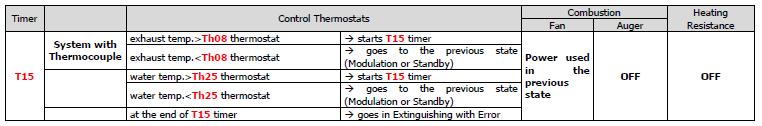
26 STAND BY: In all phases if the flue gas temperature>th08 Thermostat or water temperature>th25 Thermostat the system is in Safety. To reduce oscillations between states Standby Ignition Run Mode Standby, adjust Room Thermostat Hysteresis and Boiler Thermostat Hysteresis. Anyway Standby lasts at least 10 seconds. Setting the A27 parameter it is to get the brazier in Maintenance or in Extinguishing. Standby-Extinguishing (A27=0) When the conditions that led to the system in Standby aren t valid, the T11 timer starts (if A26=1 from Wait phase, if A26=0 from any phase). At the end the system goes in Check-Up. Extinguishing
27 SAFETY: EXTINGUISHING: BLOCK:


28 WOOD MODALITY RUN MODE: If the exhaust temperature is lower than Th13 thermostat, starts the T21 timer: if the temperature rises above this thermostat, the timer is reset, otherwise the system returns to Off state. MODULATION: STANDBY: Setting the A27 parameter it is to get the brazier in Maintenance or in Extinguishing. SAFETY: EXTINGUISHING:
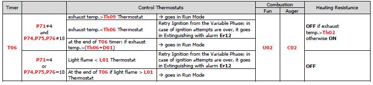
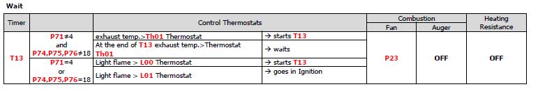
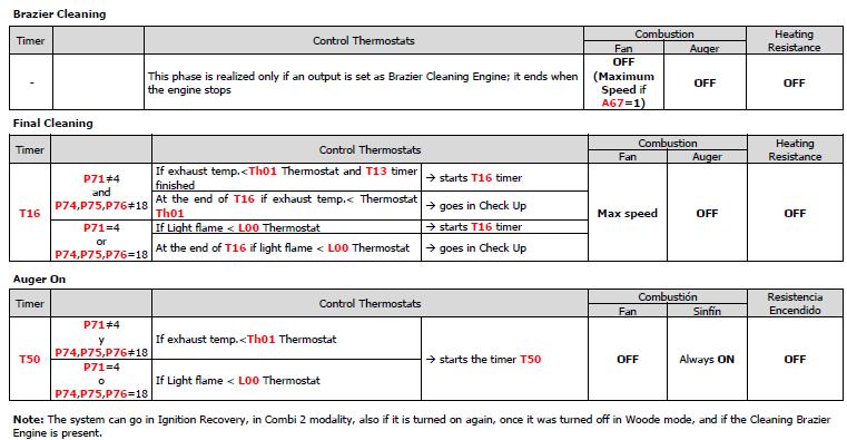
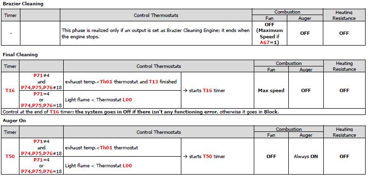
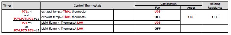
29 COMBI MODALITY By parameter P11 you can configure user-selectable modes of operation for the current system: Only Pellet Mode (P11=0) In this configuration the system can only operate at Pellet Mode and in the User Menu, the submenu functioning isn t present. Only Wood Mode (P11=1) In this configuration the system can only operate at Wood Mode and in the User menu, the submenu functioning isn t present. Wood/Pellet Mode (P11=2) In this configuration the system can operate both Pellet and Wood Mode, but not at the same time. Through the submenu functioning of the User Menu you can select the desired operation. Combi Mode 1 (P11=3) In this configuration, the system can operate in Pellet, Wood and also in combination. Through the submenu functioning of the User Menu you can select the Pellet,Wood or Combi Mode (on display appears the symbol ). The combi mode 1 allows to turn on again automatically in pellet mode, when the wood in the brazier is finish. When the system is in Pellet mode, the combi mode is deactivated. When the system is turned on, it starts in Wood Mode. If the exhaust temperature measured by the thermostat is higher than the Th13 is loaded timer T21; if later the temperature is lower than Th13 for T21 minutes the system turn on again automatically in Pellet Mode. For safety reason, the transition from wood to pellets is not allowed until the water temperature in the boiler is higher than the Boiler Thermostat. Combi Mode 2 (P11=4) In this configuration, the system can operate in Pellet, Wood and also in combination. Through the submenu Functioning of the User Menu you can select the Pellet,Wood or Combi Mode (on display appears the symbol ). The Combi mode 2 turns on the system in Pellet mode and allows to burn the wood, and finally enter in Wood Mode. When the wood is over the system goes in Pellet mode. This modality doesn t turn off automatically, to perform the Combi cycle again you must first turn the system off and then on again. In mode 2 Combined the ignition of wood with pellets is carried out considering the parameter P71. If: P71 4 and P74,P75,P76 18 are considered thermostats Th63, Th66, Th69 instead of thermostats Th03, Th06, Th09 P71=4 or P74,P75,P76=18 is considered thermostat L01 If the system passes the phases of Ignition and Stabilization, comes up to speed and starts the timer T71. During the time T71 the system can only go in Safety or Modulation / Standby for Boiler Temperature according to the parameter A13. At the exit from Standby, the system resumes from Ignition phase, restarting the Ignition of Wood with pellets. Depending on the value of the parameters PA29 and PA23, the system will work in the following way: PA29 = 0 and PA23=0 At the end of the T71 time, if the exhaust temperature is higher than Th64 thermostat, the system goes in Wood Mode otherwise, at the end of the timer, keeps working with Pellet. When the wood is over (exhaust temp < Th13 thermostat) at the end of the T21 timer, the system turns on again in pellet mode automatically(the thermostats considered are Th03, Th06, Th09). If during Pellet Mode after the end of the wood, the exhaust temperature becomes greater than Th68 thermostat, the system goes again in Wood Mode and the Combi cycle restarts. Transition from Wood to Pellet is not allowed if Door input is Open. PA29 = 0 and PA23=1 In this case, the Door input is used for the system transition to Wood. Once the system came up to speed, at the end of T71 timer, the thermostat Th64 is checked: if exhaust temperature is greater than it the system passes to Wood mode, otherwise it keeps working with Pellet. Here the system kepps checking the thermostat Th68 for the transition to Wood. If the system successfully passed to Wood, once it finished (exhaust temperature lower than the thermostat Th13) when the timer T21 expires, the system turns on again with Pellet automatically (thermostats Th03, Th06, Th09). The system keeps working with Pellet until the Door is open, and consequently closed. This condition starts the timer T71 and, from its expiring, the thermostat Th68 is checked. If exhaust temperature is greater than it the system passes to Wood, otherwise it will keep working with Pellet. For the Th68 thermostat control, the opening / closing of the door can take place both in Wood or Pellets phase. PA29 0 and PA23=1 In this case, the functioning is managed only with door present. During ignition, once fully operational, the system is brought to work to the fixed power PA29. At the end of the timer T71, Th64 thermostat is checked: if Exhaust
30 temperature is greater than it, the system passes to Wood, otherwise it will keep working with Pellet, power is not fixed to PA29 and no more controls for transition are carried out, unless the door is open (and then closed). In that case, the system fixes again the power to PA29, starts counting T71 and, when this timer expires, checks the thermostat Th68: if Exhaust temperature is greater than it, the system switches to Wood mode. When T71 timer expires, working power is no more fixed, while Th68 thermostat is still monitored. If the system successfully passed to Wood, once it finished (exhaust temperature lower than the thermostat Th13) when the timer T21 expires, the system turns on again with Pellet automatically (thermostats Th03, Th06, Th09). Now the system keeps working in Pellet mode (with not fixed power) until the Door is open, and consequently closed. That condition lead the system to fix the power at PA29 and makes the timer T71 start. When it expires, the Th68 thermostat is monitored: if exhaust temperature is greater than it, the system switches to Wood, otherwise it will keep working with Pellet. When T71 expires, working power is no more fixed, while Th68 thermostat is still monitored. For the Th68 thermostat control, the opening / closing of the door can take place both in Wood or Pellets phase. OTHER FUNCTIONS Internal Chrono Management The control board is provided with a clock module for the management of programmed switching on and off (this feature is available only in Pellet modality). Setting the parameter A32 it is possible to: A32=0 the chrono manages the system s Ignition/Extinguishing. This functioning is only available in pellet mode or in Combination mode and parameter P11 = 4 (Combi 2). A32=1 the chrono sends the system in Modulation outside the programmed time on bracket. A32=2 the chrono sends the system in Standby outside the programmed time on bracket. A32=3 the chrono blocks the plant pump outside the programmed time on bracket if the water temperature in the boiler exceeds the Th19 thermostat. If the temperature exceeds the Th21 thermostat the pump turn on. A32=4 the chrono works as in the cases 2 and 3 NOTE: If there is a sanitary water demand the pump system isn t blocked and, if it previously had been blocked, it is reactivated. If the parameter A13=2, on Summer all functioning of the Room Thermostat are disabled except the one with A01=0. Combustion Standby The Standby is a temporary shutdown of the flame due to the attainment of the target temperature of the medium to be heated. The conditions to go in Standby are managed by parameters A01, A52 and A13: A01, A52=2, 4, 5, 7 if room temperature>room Thermostat, the system goes in Standby A13=0 if boiler water temperature>thermostat Boiler, the system goes in Modulation A13=1 if boiler water temperature>(boiler Thermostat+D23) when the timer T43 is finished, the system goes in Standby A13=2 On Winter if water temperature > Boiler Thermostat the system goes in Modulation On Summer if water temperature > (Boiler Thermostat + D23) the system goes in Standby at the end of T43 Timer. To exit Standby set the values of the thermostats hysteresis. The system exits from standby if: Room temperature<(room Thermostat-Ih33-1) and Room remote temperature<(room Remote Thermostat-hysteresis-1) and water boiler temperature<(boiler thermostat-ih24-1) Automatic Combustion Power In the Combustion Power Menu, the user can set the Automatic modality [A]. The work power is automatically selected according to the water boiler temperature and the value of Boiler Thermostat Th24: boiler water temperature Th24 d08 the system goes to the maximum available power Th24 d08<boiler water temperature<th24 the combustion power decreases reaching the Boiler Thermostat boiler water temperature Th24 the system goes to Power 1 if A06=0 or to Modulation Power if A06=1-30 -
31 Change Power Delay When the system exits from the Ignition and goes in Run Mode, the Combustion Power, starting from the Power 1, reaches the target one increasing the value with the delay time as the timer T18. The other manual or automatic power changes are managed and actuated with the delay time as timer T17. System Maintenance 1 Function When the system exceeds the working hours set by the parameter T66 it is notify the user to contact the service to verify the proper functioning of the system. The display shows the message 'Service' and the system goes in Block. To unblock it is necessary to reset the counters. To disable this feature set T66=0. To enable this feature set T66>0 System Maintenance 2 Function When the system exceeds the working hours set by the parameter T67 it is notified to the user to clean the boiler or the stove. The display shows the message 'Clean' and the system gives out an acoustic signal periodically. To stop signalling enter the menu Reset Service. To disable this feature set T67=0. Extinguishing in Ignition Phase When the system is turned off during the Ignition phase (after Preheating phase) by an external device or by internal chrono, it really goes in Extinguishing when it enters the Run Mode at the end of Ignition. On display appears the message "Block Ignition". In Combi 2 modality if the system is turned off ( also with manual control): PA23 =0 the System does the extinguishing if exhaust temp. > Th64 or if T71 is expired. In the first case the extinguishing is performed in Wood modality, in the second case in Pellet modality. Furthermore in this case, if exhaust temp. > Th68 the extinguishing switches to Wood modality. PA23 = 1. The System, when T71 expires, checks exhaust temperature. If it s greater than Th64 extinguishing is performed in Wood mode, otherwise in Pellet mode., the system goes on with the extinguishing in pellet modality. If exhaust temperature is > Th64 the system starts a checking procedure, similar to that of Wood transition described in section 6.3. In this case, the system can switch to Wood extinguishing. Furthermore in this case, if exhaust temp. > Th68 the extinguishing switches to Wood modality If it occurs any error, the system goes immediately in Extinguishing with error. If the P2 button is pressed it is possible to get immediately the system in Extinguishing or in Ignition. Automatic switch off function If the parameter A40=1 and the functioning is in Pellet modality the system, after T84 minutes in Run Mode, Modulation and Standby-Maintenance goes in Recover Ignition. Supply Voltage Lack Management In case of supply voltage lack, the system saves the most important functioning data. With the return of the supply voltage, the system evaluates the saved data and, according to parameter A53 we have: A53=0 o If the lack is less than T88 the system returns to the state in which it was previously o If the system was in a On state and the lack of voltage is between T88 and T89 the system goes in Recover Ignition, if it is in Pellet modality; it goes in Run Mode if in Wood modality o In case of lack of Supply Voltage for a time greater than T89 the system goes in Block with error message Er15 A53=1 o If the lack is less than T88 the system returns to the state in which it was previously o If the system was in a On state and the lack of voltage is greater than T88 the system goes in Recover Ignition, if it is in Pellet modality; it goes in Run Mode if in Wood modality Auger Feeding in Wood Modality When the system is in Wood modality and in the states Run Mode and Modulation is possible to feed the Auger and download pellets in the brazier. If the flue gas temperature is greater than Th13 thermostat, the Auger is off for the time T53 and it is on for the time T54; if a configurable output is set as the Safety Valve (P44 or P48 or P36=1) the Auger is turned on only at the end of time T40. If the Combustion Fan was off, it is turned on at the speed U12, otherwise it continues to work on the power to which it was working. If the fuel in the tank is run out, the function is disabled
32 Periodical Cleaning of Brazier Periodical Cleaning of brazier occurs in Run Mode for a time T08 with a repetition time equal to T07 timer. During the cleaning phase the, Exhaust Fan goes to at U09 power and the Auger at C09. Configurable Outputs Management It is possible to configure the outputs V2 (pins 5-6), Aux2 (pins ) and Aux3 (pins ) setting the parameter P44, P48 and P36. Safety Valve The output is on when the Auger is enabled to work; the Auger will be on only at the end of timer T40. Preheating phase of the Ignition phase, the Safety Valve work phase of Standby-Maintenance and the Auger feeding in Wood modality will only start if the timer T40 expires. State System Check Up, Ignition, Stabilisation, Run Mode, On Modulation, Standby-Maintenance (work phase), Safety, Extinguishing (Advancement Auger phase) Other States Off Load Pellet Engine When the Pellet Level Sensor signals the absence of pellet, the output is activated to do the loading of the tank. If in a time T24 is not reached the set pellet level, the system goes in Extinguishing and the display shows the message Er18. If the tank is filled manually, it is possible to reset the error and restart the system. If the set pellet level is reached, the loading of the material continues for a time equal to T23. Output under Thermostat The output is managed by Th56 Thermostat: above this value is supplied
33 12.1 START UP First start up work shall be carried out exclusively by fully trained, professionally qualified personnel. Please read the installation, operation, use and maintenance manuals before start up Before first start up check that; There is a copy of the boiler and burner instructions in the boiler room. The boiler name plate and manual specifications and power supply network and other system need specifications corresponds to each other. (electric supply, fuel, water, boiler and burner output, system pressure, circulating pipes ) The air inlet and outlet supply openings are correctly sized and free from obstacles. The flue gas exhaust system is correctly fitted and sized. All the system control and security devices are present and installed according to the current regulations and working properly. The burner output and fuel type is compatible with the boiler and system specifications. The flue gas turbulators are present in all the second pass pipes and properly placed. Control the boiler gas side seals are not damaged and fixed properly. (boiler front door, burner mounting plates, smoke box, flame monitoring glass) At starting a new installation all the fuel and water pipes, boiler and all the other heating system items must be flushed and free from deposits. Before filling the system with water, control the expansion tank pre charge pressure in sealed systems. Open all the necessary valves for filling Fill the heating system with water (water specifications shall be according to boiler manuals) very slowly according to the air bleeding capacity of the components. In open vented systems fill the system up to expansion cistern s proper level. In sealed systems fill the system up to the predefined pressure. In sealed systems there must be an additional safety system for overheating approved by local authorities. Bleed all the air in the water side. Be sure that any air blockage have been eliminated. Run the circulating pumps and control that they are working properly. Control all the possible water leakage points. Check all security and operation items are working properly and set to system needs. If the safety valve is not factory adjusted, set it according to system need and be sure that it is working properly. Control the fuel system installation Fill the pellet feeding screw. Make pellet calibration process. Before firing the burner, be sure that system is full of water and all control items are set to desired value and working properly. Run the burner and adjust it to proper output according to boiler needs. Analyze the flue gas and be sure that emission levels of CO, O2, OGC, Dust and NOx where appropriate are according to current regulations. For reference (current and national regulations have to be taken into consideration) Limits of emissions mg/m3 at 10 % O2 a) Emission class C0 mg/m3 CO (mg/kwh) NOx (mg/kwh) a) Referred to dry flue gas at 0 ⁰C and 1,013 bar Note: Emission values shall be according to current and local limitations. In absence of local limitations refer to current pren and/or current EN In correct adjustments can cause damage to people, animals, nature and also loss of energy
34 After running the burner heat the system up to 80 C and again bleed the air in the entire system. After first heating most of the dissolved air in the system water will be free for bleeding. Control all the security and operation devices for proper operation and set values are according to system needs again. Call the owner or operator of the boiler house and give the necessary information for proper operation of the system and warn them about the possible dangers and limitations and what will they do in case of emergency


35 FAULT INDICATION Both the keyboard touch screen and LCD you can view the messages on the main screen such as error messages. -Errors: All errors make the security system block except errors Er04 and Er05 to wood
36 12. MAINTANACE AND SERVICING 13.1 FOR PELLET Do not open any part on the boiler or burner when the system is running. Please stop the burner and wait up to no flame condition, after 30 minutes disconnect the power supply and always wait until all the parts are cooled down before cleaning and servicing operations. In order to extend the lifetime and increase efficiency at every heating season or once a year please call your authorized service to; Clean the boiler heat exchanger surfaces Check the combustion parameters Check the security and operational devices Check the adequate chimney draught Cleaning period depends on plant features, fuel and combustion parameters so after first commissioning please control the burner and boiler heat exchange surfaces once a month, if they need any cleaning. After few controls you can decide the period of cleaning you will need. Stop the burner Wait for cooling the boiler (min 2 hour) Stop the circulation pump Disconnect the main power supply Dismantle the burner and check the combustion pipe. If it needs cleaning please dismantle the combustion pipe and clean all surfaces. Dismantle the top boiler jacket Dismantle the boiler top cover Take out the turbulators Clean the 2 nd pass pipes by tube brush Open the bottom ash door and control the ash box. If needed clean manually. Put back all the dismantled part in its proper place in reverse order. Connect the main power And run the system. Again once a year call your authorized service for checking the combustion parameters, security and operational devices. Do not alter the security devices preset values Reset the burner fault maximum 3 times and still not firing call your authorized service If the flue gas seals in any part of the boiler and flue gas exhaust is not functioning properly and there is a flue gas leakage stop the burner and please call an authorized service for repair or replacement. Check the makeup water analysis periodically to avoid the formation of scale and corrosion which initially reduces the system efficiency and in long term will permanently damage the boiler. Periodically check the safety and operational equipments. During the long shut off periods run the circulation pump(s) and anti-condensation pump 5 min/month in order to avoid pump shaft lock-out. Frequent make up water need should be nonexistent it is a symptom of leakage which should be repaired as soon as possible. Adding water to the system will shorten the life of the boiler dramatically. System water never fully drained if it is not necessary. Corrosion is very rapid in empty systems. New water filling means adding new scale and oxygen to the system. Both reasons cause to shorten the boiler service life and cause loss of efficiency
37 System water level must be checked minimum once a month. At the fist installation it needs regular check because of air discharge from the system. Chimney must be cleaned periodically according to the national regulations minimum once a year. If the system will be shut off for long periods in winter time please take precautionary actions for freezing the system water. Water filters shall be cleaned regularly according the system need. Please be sure that the boiler cannot suck extra air from any opening. Control all the doors are closed tight and gaskets are not damaged. Before the heating season starts, please buy only kg of pellets according to specifications given, and after seeing that you do not have any problem, please buy the rest of the pellets you will need for that heating season. Small changes in the pellet specifications can affect your system parameters. Chimney is also very important part of the heating system. You must have always negative pressure ( -1 / -8 Pa) when the boiler fan is not running. Positive pressure can carry back the hot poisonous flue gases to boiler house. Too much negative pressure will also cause problem. Boiler fan may not control the set pressure under very high vacuum. If you have high vacuum in the chimney please use draught stabilizer. Please install a standard temperature indicator to the hot water return line to the boiler. You can check the condensation risk (return temperature must be > 55 C) and also you can control your circulation pump capacity. (Feed and return temperature difference must be between C if it is more than 26 C it means that your pump is small for the system)

38 13. BOILER NAME PLATE COMMISIONING DATE : /. / COMMISIONED BY : NAME : TEL : INTIAL SET VALUES Fuel type: System pressure: mbar
EasyTech.One Temperature Controller for Pellet Burner
 EasyTech.One Temperature Controller for Pellet Burner Burner 1 INTRODUCTION... 3 2 ELECTRICAL CONNECTIONS... 3 3 CONTROL PANEL: USE AND FUNCTIONS... 5 3.1 LED... 5 3.2 BUTTONS... 5 3.3 ALARMS... 5 3.1
INSTRUCTIONS FOR USE OF COMBINED BOILER INTENDED FOR COMBUSTION OF BOTH PELLETS AND SOLID FUEL ABC COMBO
 INSTRUCTIONS FOR USE OF COMBINED BOILER INTENDED FOR COMBUSTION OF BOTH PELLETS AND SOLID FUEL ABC COMBO .Technical specifications Boiler power DESCRIPTION Water content in a boiler Required draft Supply
SY250 IDRO 4/8 BUTTONS MANUAL
 SY250 IDRO 4/8 BUTTONS MANUAL Pag. 1 / 44 Summary 1 INTRODUCTION... 4 2 INSTALLATION... 4 2.1 CONNECTIONS... 4 2.2 DIGITAL INPUTS... 7 2.2.1 Safety High Voltage 1... 7 2.2.2 Safety High Voltage 2... 7
USER MANUAL 9kW LILLY PELLET STOVE
 USER MANUAL 9kW LILLY PELLET STOVE Table of Contents.Overview of Stove Parts... 2.Technical Characteristics... 3 3.Important Information... 4 4.Pellet Specification...5 5.Technology... 6 6.Installation...
EasyTech.Full Temperature Controller for Pellet Stove. Idro
 EasyTech.Full Temperature Controller for Pellet Stove EasyTech.One is a Pellet stoves control system available in Air and Hydro version. Is characterised by: Installing and use simplicity Simple and direct
INSTALLATION AND OPERATING INSTRUCTIONS BIOCLASS HM
 INSTALLATION AND OPERATING INSTRUCTIONS BIOCLASS HM Thank you for choosing a DOMUSA TEKNIK heating boiler. Within the product range offered by DOMUSA TEKNIK you have chosen BioClass HM model. With a suitable
BIX B-One 100 kw INSTALLATION GUIDE
 BIX B-One 100 kw INSTALLATION GUIDE Dear Customer, We thank you for choosing our product. The Bix B-One 100 Kw is a burner of advanced concept and technology, with a high reliability and construction quality.
TECHNICAL INSTRUCTIONS USE AND MAINTENANCE
 TECHNICAL INSTRUCTIONS USE AND MAINTENANCE Cm Pelet-set For boilers CentroPlus 25/35 and CentroPlus-B 25/35 (solid fuel and wood pellets fuel firing) TUPSCP-K-11-2016-ENG CONTENTS 1.Introduction 2. Status
Residential Gas Condensing Boiler Greenstar ZBR16/21/28/35/42-3A... ZWB28/35/42-3A...
 70 80 99-00-O Residential Gas Condensing Boiler ZBR//8/35/4-3A... ZWB8/35/4-3A... 70 80 993 (03/03) CA/US Operating Instructions Contents Contents Key to symbols and safety instructions............................
INSTALLATION AND OPERATING INSTRUCTIONS BIOCLASS HM OD (FOR EXTERNAL USE)
") INSTALLATION AND OPERATING INSTRUCTIONS BIOCLASS HM OD (FOR EXTERNAL USE) Thank you for choosing a DOMUSA TEKNIK heating boiler. Within the product range offered by DOMUSA TEKNIK you have chosen BioClass
INSTALLATION AND OPERATING INSTRUCTIONS BIOCLASS HM OD (FOR EXTERNAL USE) Thank you for choosing a DOMUSA TEKNIK heating boiler. Within the product range offered by DOMUSA TEKNIK you have chosen BioClass
USE AND MAINTENANCE. Cm Pelet-set (60-90 kw) TECHNICAL INSTRUCTIONS
 TECHNICAL INSTRUCTIONS") CENTROMETAL d.o.o. Glavna 12 40306 Macinec Croatia tel: +385 40 372 600; fax : +385 40 372 611 TECHNICAL INSTRUCTIONS USE AND MAINTENANCE Cm Pelet-set (60-90 kw) For boilers: EKO-CK P 70-110 TUPS-90K-09-2015-E-N-eng
CENTROMETAL d.o.o. Glavna 12 40306 Macinec Croatia tel: +385 40 372 600; fax : +385 40 372 611 TECHNICAL INSTRUCTIONS USE AND MAINTENANCE Cm Pelet-set (60-90 kw) For boilers: EKO-CK P 70-110 TUPS-90K-09-2015-E-N-eng
Operating instructions
 Operating instructions Gas-fired condensing boiler Logano plus GB312 For the user Please read carefully before use 7 747 009 296-01/2007 EN Contents 1 For your safety..............................................
Operating instructions
 Operating instructions Gas condensing boiler WARNING: If the information in this manual is not followed exactly, a fire or explosion may result causing property damage, personal injury or loss of life.
Electronic Pellet Burner Controller NPBC-V3M
 Electronic Pellet Burner Controller NPBC-V3M SOFTWARE VERSION 3.3a/3.2 page of 27 CHANGES IN THE USER MANUAL OR IN THE CONTROLLER'S SOFTWARE Version of the user manual Changes Page 2.2. The software version
PELLET BURNER PV 350
 PELLET BURNER PV 350 INSTRUCTION MANUAL v1.1 1 PRODUCT DESCRIPTION...3 2 SAFETY RULES...3 3 WARNINGS...4 4 INSTALLATION INSTRUCTIONS...5 4.1 BOILER REQUIREMENTS...5 4.2 PELLET CONTAINER...6 4.3 INSTALLATION
OPERATION, USE AND MAINTENANCE MANUAL
 BÜYÜKELÇI SOK. NO:9 06700 KAVAKLIDERE ANKARA TURKEY TEL: +90 312 468 09 11 FAX: +90 312 468 45 96 E-MAIL: ari@tr.net VENTUM SERIES WOOD FIRED GASIFICATION HOT WATER BOILERS VG-20, VG-30, VG-40, VG-60,
USERS MANUAL FOR GAS BOILERS
 USERS MANUAL FOR GAS BOILERS PLEASE READ THE MANUAL CAREFULLY: IT CONTAINS IMPORTANT INFORMATION REGARDING SAFETY, INSTALLATION, USE AND MAINTENANCE OF THE APPLIANCE MODELS: NOVADENS 24 NOVADENS 24C NOVADENS
Aqua Balance. AquaBalance TM CONTROL MODULE QUICK START GUIDE LEGEND
 Aqua Balance AquaBalance TM CONTROL MODULE QUICK START GUIDE 10 1 Domestic Hot Water temperature setpoint decreasing button 2 Domestic Hot Water temperature setpoint increasing button 3 Central Heating
A.D. METALNA INDUSTRIJA VRANJE Radnička br: 1 PELLET BOILER GRANDE
 A.D. METALNA INDUSTRIJA VRANJE Radnička br: 1 PELLET BOILER GRANDE INSTRUCTIONS FOR USE, MAINTENANCE AND INSTALLATION ENG_V.1.0_Jun2016 DEAR CUSTOMERS!!! Thank you for purchasing the GRANDE Boiler. Please
T UNI 7000 F. Operating instructions For the user (2006/05) AU/GB
 AU/GB") 6 720 648 662-00.1T UNI 7000 F Operating instructions For the user AU/G 2 Contents Contents Contents 2 1 Safety information and explanation of symbols 3 1.1 For your safety 3 1.2 Explanation of symbols
6 720 648 662-00.1T UNI 7000 F Operating instructions For the user AU/G 2 Contents Contents Contents 2 1 Safety information and explanation of symbols 3 1.1 For your safety 3 1.2 Explanation of symbols
1 DOCUMENT REVISION CONTROL ELEMENTS... 9
 CONTENTS Contents 1 DOCUMENT REVISION... 8 2 SOFTWARE VERSION... 8 3 BASIC DESCRIPTION... 8 4 CONTROL ELEMENTS... 9 4.1 BASIC DISPLAYS...10 4.2 CONTROL KEYS...11 4.2.1 Rotary button (Press / Turn)...11
CentroPelet ZV14 TECHNICAL INSTRUCTIONS HEATING TECHNIQUE. for regulation, use and maintenance of pellet stove
 HEATING TECHNIQUE Centrometal d.o.o. - Glavna 12, 40306 Macinec, Croatia, tel: +385 40 372 600, fax: +385 40 372 611 TECHNICAL INSTRUCTIONS for regulation, use and maintenance of pellet stove CentroPelet
JUMBO INDIRECT FIRED DIESEL HEATER OPERATING INSTRUCTIONS
 JUMBO INDIRECT FIRED DIESEL HEATER OPERATING INSTRUCTIONS Before using the heater, read and understand all instructions and follow them carefully. The manufacturer is not responsible for damages to goods
INSTRUCTION FOR THE USER THC V E OIL BLU
 INSTRUCTION FOR THE THC V E OIL BLU CONTENTS General safety information 4 Precautions 4 Control panel 5 Mode selection 8 User levels 10 Start-up 12 Temporary shutdown 15 Preparing for extended periods
USE AND MAINTENANCE. Cm Pelet-set TECHNICAL INSTRUCTIONS. (14-35 kw) For boilers: EKO-CK P (EKO-CK 20-40) EKO-CKB P (EKO-CKB 20-40)
 For boilers: EKO-CK P (EKO-CK 20-40) EKO-CKB P (EKO-CKB 20-40)") TECHNICAL INSTRUCTIONS USE AND MAINTENANCE Cm Pelet-set (14-35 kw) For boilers: EKO-CK P 20-40 (EKO-CK 20-40) EKO-CKB P 20-40 (EKO-CKB 20-40) TUPS-K-02-2011-E-N-ENG CONTENTS 1. Introduction....... 2. Status
TECHNICAL INSTRUCTIONS USE AND MAINTENANCE Cm Pelet-set (14-35 kw) For boilers: EKO-CK P 20-40 (EKO-CK 20-40) EKO-CKB P 20-40 (EKO-CKB 20-40) TUPS-K-02-2011-E-N-ENG CONTENTS 1. Introduction....... 2. Status
Operating Instructions
 Operating Instructions Low Emissions and High Efficiency Condensing Oil Boiler DANGER! If these instructions are not followed exactly, a fire or explosion may be caused with serious property damage or
Residential Gas Condensing Boiler Greenstar combi 100 p / 151 p ZWB28-3A... ZWB42-3A...
 Residential Gas Condensing Boiler Greenstar combi 00 p / 5 p ZWB8-3A... ZWB4-3A... Operating Instructions 708733 (07/04) US/CA Contents Contents Explanation of symbols and safety instructions.......................
Electronic Pellet Burner Controller NPBC-V3-1
 Electronic Pellet Burner Controller NPBC-V3- SOFTWARE VERSION 3.2/3. page of 3 CHANGES IN THE TECHNICAL AND USER GUIDE OR IN THE SOFTWARE VERSION Technical and User Guide's version Changes Page 2.8. The
User s Information Manual Models: ER152, ER202, ER252, ER302, and ER402
 ERP-USER_100161005_2000003726_Rev D User s Information Manual Models: ER152, ER202, ER252, ER302, and ER402 If the information in this manual is not followed exactly, a fire or explosion may result causing
Combined boiler. for solid fuel and pellets
 Combined boiler ATTACK WOOD&PELLET for solid fuel and pellets W W W. A T T A C K. S K MODEL STRUC TURE OF THE AT TACK BOILERS THE NEW LINE OF ATTACK BOILERS FOR WOOD AND PELLETS 3000 000 6000 4 ATTACK
Corn Flame Energy Corn Stove Model 3000
 Corn Flame Energy Corn Stove Model 3000 Installation and Operation Guide Read thoroughly before starting installation Save this manual for future reference SAFETY NOTICE If this stove is not properly installed,
TECHNICAL MANUAL BIOTEC 25 AND BIOTEC 40
 TECHNICAL MANUAL BIOTEC 25 AND BIOTEC 40 2 INDEX INDEX Safety information.......4 Technical data...5 Boiler features...6 Technical information........7 Fuel...... 8 Construction and function...... 9 Hydraulic
User Manual. Dryer Controller M720
 User Manual Dryer Controller M720 Hardware version 1.00 Software version 1.00 Preliminary version Manual M720 Dryer controller Page 1 of 42 Document history Preliminary version: - Created in April, 2009
USERS GUIDE. LOGIC+ Combi 24, 30, 35
 USERS GUIDE LOGIC+ Combi 24, 30, 35 When replacing any part on this appliance, use only spare parts that you can be assured conform to the safety and performance specification that we require. Do not use
Logic+ Combi
 USER GUIDE Logic+ Combi 24 30 35 When replacing any part on this appliance, use only spare parts that you can be assured conform to the safety and performance specification that we require. Do not use
/2010 US/CA
 6 720 646 148-11/2010 US/CA (en) For the user User s Instructions Condensing gas boiler Logamax plus GB162-L.B. 80 kw/100 kw Please read thoroughly before operating This manual is available in the English
USERS GUIDE 24, 30. For installation guide see reverse of book
 USERS GUIDE 24, 30 For installation guide see reverse of book When replacing any part on this appliance, use only spare parts that you can be assured conform to the safety and performance specification
USER MANUAL ACQUAHOME 32 B BLU
 USER MANUAL ACQUAHOME 32 B BLU Dear Customer, Thank you for preferring a T heating unit, a modern, high-quality product that is able to guarantee your maximum well-being for a long period of time, with
INSTRUCTIONS FOR ASSEMBLY, USE, AND MAINTENANCE PELLET STOVE LUCA S/LUKA S8
 WARNING: This user manual is an integral part of the product. It has to be kept and read carefully. EN INSTRUCTIONS FOR ASSEMBLY, USE, AND MAINTENANCE PELLET STOVE LUCA S/LUKA S8 1. Introduction Firstly,
INSTRUCTION MANUAL & SERVICE MANUAL ORLIGNO 400
 INSTRUCTION MANUAL & SERVICE MANUAL ORLIGNO 400 Content 1. Delivery......................................................................... 3 2. Installation and assembly.........................................................
Operating instructions
 The energy you need Operating instructions Betacom 3 24c -A (H-GB) 30c -A (H-GB) GB, IE Contents Contents 1 Safety... 3 1.1 Action-related warnings... 3 1.2 Intended use... 3 1.3 General safety information...
User Manual RBS 24. for model CE series ENERGY. Wall mounted instantaneous combi boiler room sealed chamber
 User Manual for model RBS 24 series ENERGY Wall mounted instantaneous combi boiler room sealed chamber CE 0694 RBS 24 - SERIE ENERGY - RAD - ING - MAN.UT - 1407.1 - DIGITECH TR - MIAH6 - E04 Technical
Installation and user manual
 Installation and user manual Please read carefully and retain for future reference Models EcoHeat: C3, C5, C6, C8, C9, C11, C12 Rev.1_09-07-15 Page 1 Table of Contents 1 IMPORTANT: WARNINGS 1.1 GENERAL
THERMAX Efficiency Monitor
 INSTALLATION & OPERATION INSTRUCTIONS THERMAX Efficiency Monitor Oil & Gas Fired Heating Equipment Efficiency Monitoring Instrument Important Safety Instructions Read and safe these instructions before
i 24, i 30, i 35 combination boilers USER GUIDE For Installation Guide see reverse of book UIN A05 October 2017
 24 1 2 23 3 4 5 20 6 I 19 7 18 8 9 15 14 11 13 12 i 24, i 30, i 35 combination boilers USER GUIDE For Installation Guide see reverse of book i 24 OFF MAX E STATUS BURNER RESET MIN PRE MIN MAX HEAT PREHEAT
British Gas 330+ High Efficiency Condensing Boiler. Instructions for Use. To b e l e f t w i t h t h e u s e r. British Gas Service Tel:
 0020051423-02 10.07 British Gas 330+ High Efficiency Condensing Boiler Instructions for Use To b e l e f t w i t h t h e u s e r British Gas Service Tel: 0845 9500400 WARNING GAS LEAK OR FAULT Turn off
METAL INDUSTRY VRANJE
 METAL INDUSTRY VRANJE st:radnička n-1 PELLET STOVE LUCA S / LUCA S8 WARNING:This user manual is an integral part of the product.it has to be kept and read carefully. INSTRUCTIONS FOR ASSEMBLY, USE, AND
VIESMANN. Operating instructions VITODENS VITOPEND. for the system user. Heating system with Vitotronic 100 control unit for constant temperature mode
 Operating instructions for the system user VIESMANN Heating system with Vitotronic 100 control unit for constant temperature mode VITODENS VITOPEND 4/2007 Please keep safe. Safety instructions For your
HIGH EFFICIENCY FIRETUBE CONDENSING GAS BOILER
 This manual must be left with owner and should be hung on or adjacent to the boiler for reference. US HIGH EFFICIENCY FIRETUBE CONDENSING GAS BOILER MODELS CHS-85 through CHS-399 APPENDIX A CONTROLLER
INSTALLATION AND OPERATING INSTRUCTIONS. Ariterm 60+
 INSTALLATION AND OPERATING INSTRUCTIONS Ariterm 60+ CONTENTS General.... 2 Installation.... 4-5 Installation of temperature limit valve... 6 Measurements and connections... 7 Technical specifications and
Operating instructions
 Operating instructions Capriz 2 24c 28c GB, IE Contents Contents 1 Safety... 3 1.1 Action-related warnings... 3 1.2 Intended use... 3 1.3 General safety information... 4 2 Notes on the documentation...
E-COMBI EVO E-SYSTEM EVO
 E-COMBI EVO E-SYSTEM EVO User s manual CONDENSING WALL-HUNG GAS BOILER G.C.N.:47-116-68 (24 kw) G.C.N.:47-116-69 (30 kw) G.C.N.:47-116-70 (38 kw) G.C.N.:41-116-39 (24 kw) G.C.N.:41-116-40 (30 kw) Country
USER GUIDE VOGUE COMBI GEN2 C26 C32 C40
 USER GUIDE VOGUE COMBI GEN2 C26 C32 C40 When replacing any part on this appliance, use only spare parts that you can be assured conform to the safety and performance specification that we require. Do not
INSTALLATION AND OPERATION MANUAL
 INSTALLATION AND OPERATION MANUAL PRESSURISED STEEL BOILERS AR 30 AR 1000 RADIALAND - BOILER's INSTALLATION MANUAL version 1.0 / 15-02-2008 The company E. is outstanding in the field of central heating
USER S INFORMATION MANUAL
 USER S INFORMATION MANUAL HOT WATER HEATING BOILERS DOMESTIC WATER HEATERS 150,000-300,000 Btu/hr MODELS EB-EWU-02 IMPORTANT INSTALLER - AFFIX INSTALLATION MANUAL ADJACENT TO THE BOILER CONSUMER - RETAIN
heat interface units A BOILER WITHOUT A FLAME
 A BOILER WITHOUT A FLAME heat interface units Communal Heat Networks A central boiler house will generate heat which is distributed through a network of pipe to each home or apartment in the building.
OPERATION MANUAL RK-2006LPP AUGER FITTED SOLID FUEL BOILER TEMPERATURE CONTROLLER. Version DC19
 OPERATION MANUAL RK-2006LPP AUGER FITTED SOLID FUEL BOILER TEMPERATURE CONTROLLER Version DC19 1. Application. Controller RK-2006LPP is designed for temperature control of solid fuel fired water boilers
E-COMPACT TWIST kW HE Condensing Pellet Boiler
 E-COMPACT TWIST 25 100kW HE Condensing Pellet Boiler UIN-UK201505.06 INSTALLATION, OPERATION AND MAINTENANCE MANUAL Please read these instructions carefully before installing and/or lighting the appliance
Dryer Controller M720
 User Manual Dryer Controller M720 Hardware version 2.00 Software version 2.00 Manual M720 Dryer controller Page 1 of 60 Document history Preliminary version: - Created in April, 2009 Hardware Version 2.00,
WHE 2.24 / WHE 2.24 FF
 EN Wall-hung gas boilers WHE 2.24 WHE 2.24 FF User Guide 300011777-001-C . Contents 1 Introduction.............................................................................3 1.1 Symbols used...........................................................................................3
USERS GUIDE. Esprit eco 24, 30. For installation guide see reverse of book
 USERS GUIDE Esprit eco 24, 30 For installation guide see reverse of book When replacing any part on this appliance, use only spare parts that you can be assured conform to the safety and performance specification
ClearFire. Startup Guide. Model CFH. Horizontal Steam Boiler
 ClearFire Model CFH Horizontal Steam Boiler Startup Guide 750-293 www.cleaverbrooks.com Improper installation, adjustment, service, or maintenance can cause equipment damage, personal injury, or death.
Installation Manual. Instrucciones de instalación y manual de usuario 1
 Installation Manual Instrucciones de instalación y manual de usuario 1 Installation instructions and user manual V8 2 INDEX 1 GENERAL SAFETY WARNINGS... 4 2 OPERATING PRINCIPLE... 5 3 TECHNICAL FEATURES...
User s Information Manual Models: 45, ,000 Btu/hr
 SBR-USER_100161678_2000017137_Rev C User s Information Manual Models: 45,000-260,000 Btu/hr If the information in this manual is not followed exactly, a fire or explosion may result causing property damage,
I n s t r u c t i o n m a n u a l f o r b u i l t - i n h o o d. Model code: BORA600
 I n s t r u c t i o n m a n u a l f o r b u i l t - i n h o o d Model code: BORA600 Contact Caple on 0844 8003830 or for spare parts www.4caple.co.uk 1 Y O U R A P P L I A N C E Thank you for buying your
Climapro 2. User manual. wireless room thermostat without receiver. To be left with the user.
 Climapro 2 User manual To be left with the user wireless room thermostat without receiver www.glow-worm.co.uk table of contents READ CAREFULLY BEFORE USING 1 Introducing your Climapro 2... 3 1.1 Description...
Baxi Maxflow Combi WM
 Baxi Maxflow Combi WM Gas Fired Wall Mounted Combination Boiler with Unvented Hot Water Storage Please keep these instructions safe. Should you move house, please hand them over to the next occupier. User
Operation and maintenance manual for the. KSP Spark. series boilers equipped with feeders
 Operation and maintenance manual for the KSP Spark series boilers equipped with feeders Thank you for purchasing PEREKO heating boiler. This documentation applies to the KSP Pelet boilers with fuel feeder
Boiler Technical Specifications (2013)
") ACT Bioenergy Boiler Dimensions 0.5-0.85 Million Btu/h (150-250kW) Model CP500 CP600 CP750 CP850 Heat Output in MBtu/h (kw) 510 (150) 610 (180) 750 (220) 850 (250) Height ft (mm) 6 1 (1855) 6 1 (1855)
ACT Bioenergy Boiler Dimensions 0.5-0.85 Million Btu/h (150-250kW) Model CP500 CP600 CP750 CP850 Heat Output in MBtu/h (kw) 510 (150) 610 (180) 750 (220) 850 (250) Height ft (mm) 6 1 (1855) 6 1 (1855)
So old fashioned... As the combustion chamber is completely room sealed, it does not release any smells and does not dirty.
 ARREDO E BENESSERE So old fashioned... An intelligent choice When on a cold winters night the warm glowing flames of the KALDUS boiler are there to welcome you back home, you will be pleased that you decided
TermEfekt USER S MANUAL AIR HEATER. Model PGA 14
 Przedsiębiorstwo Produkcyjno-Wdrożeniowe ARAJ sp. z o.o. 55-080 Kąty Wrocławskie, ul. Mireckiego 30 POLAND USER S MANUAL AIR HEATER TermEfekt Model PGA 14 Kąty Wrocławskie, 2004 Product identification
VIESMANN. Operating instructions VITODENS 050-W. for the system user. With constant temperature or weather-compensated control unit
 Operating instructions for the system user VIESMANN With constant temperature or weather-compensated control unit VITODENS 050-W 9/2014 Please keep safe. Safety instructions For your safety Please follow
ecomax 200 W Boiler regulator FOR SOLID FUEL BOILERS WITH A FAN OPERATION AND MAINTENANCE MANUAL ISSUE:
 Boiler regulator ecomax 200 W FOR SOLID FUEL BOILERS WITH A FAN OPERATION AND MAINTENANCE MANUAL ISSUE: 1.3 APPLICABLE TO SOFTWARE 10.034 10.035 10.036 2010-04-14 TABLE OF CONTENTS 1 Safety... 4 2 General
AIREX 2S WOOD PYROLYSIS SUCKING FAN
 AIREX S WOOD PYROLYSIS SUCKING FAN To optimize green energy AIREX S constitutes the evolution of the firewood boilers range: total gasification inverted flame with sucking fan especially suitable to the
DPC-1 Programmable digital thermostat with communication Versión 2.0. Technical Information. Ref: N
 DPC-1 Programmable digital thermostat with communication Versión 2.0 Ref: N-27360 1108 Technical Information I S O 9 0 0 1 ER-0028/1991 Johnson Controls Manufacturing España, S.L. is participating in the
Smart Smart IR. Service instruction SALES DATE MANUFACTURED ON (DATE): APPROVAL MARK SOLD. model (check applicable) is recognized as serviceable
: APPROVAL MARK SOLD. model (check applicable) is recognized as serviceable") Smart Smart IR model (check applicable) is recognized as serviceable Service instruction SALES DATE MANUFACTURED ON (DATE): SOLD APPROVAL MARK SMART-EN-04 BLAUBERG Company is happy to offer your attention
Smart Smart IR model (check applicable) is recognized as serviceable Service instruction SALES DATE MANUFACTURED ON (DATE): SOLD APPROVAL MARK SMART-EN-04 BLAUBERG Company is happy to offer your attention
Ultracom cxi. Instructions for Use. High Efficiency Condensing System Boilers. To b e l e f t w i t h t h e u s e r.
 Ultracom cxi High Efficiency Condensing System Boilers Instructions for Use To b e l e f t w i t h t h e u s e r WARNING GAS LEAK OR FAULT Turn off the gas emergency control valve immediately. Eliminate
DIGITAL MODULATING BOILERS
 DIGITAL MODULATING BOILERS FOR HEATING AND SANITARY HOT WATER CMX15 CMX18 CM15 CM18 INSTALLATI INSTRUCTIS AND USER GUIDE Please read these instructions before installing or using this appliance for the
User instructions DHP-AT
 User instructions DHP-AT VUGFC202 If these instructions are not followed during installation and service, Danfoss A/S liability according to the applicable warranty is not binding. Danfoss A/S retains
Pellet burner PV 180a. User manual
 Pellet burner User manual Table of content Table of content...2 Description...5 Fuel...7 Installation...7 Boiler requirements...8 Pellet container...11 Burner...12 External auger...20 Electrical connections...21
Combi C30 & C35. User Guide FAN POWERED HIGH EFFICIENCY MODULATING DOMESTIC CONDENSING GAS COMBINATION BOILER
 Combi C30 & C35 User Guide FAN POWERED HIGH EFFICIENCY MODULATING DOMESTIC CONDENSING GAS COMBINATION BOILER When replacing any part on this appliance, use only spare parts that you can be assured confirm
Baxi Maxflow Combi FS
 Baxi Maxflow Combi FS Gas Fired Floor Standing Combination Boiler with Unvented Hot Water Storage Please keep these instructions safe. Should you move house, please hand them over to the next occupier.
Cm Pelet-set (60-90 kw)
") CENTROMETAL d.o.o. Glavna 12 40306 Macinec Croatia tel: +385 40 372 600; fax : +385 40 372 611 TECHNICAL INSTRUCTIONS FOR THE COMMISSIONING AND ADJUSTMENT Cm Pelet-set (60-90 kw) For boilers: EKO-CK P
CENTROMETAL d.o.o. Glavna 12 40306 Macinec Croatia tel: +385 40 372 600; fax : +385 40 372 611 TECHNICAL INSTRUCTIONS FOR THE COMMISSIONING AND ADJUSTMENT Cm Pelet-set (60-90 kw) For boilers: EKO-CK P
General safety precautions English
 English 1 1 1.1 About the documentation The original documentation is written in English. All other languages are translations. The precautions described in this document cover very important topics, follow
Installation & Manual. Model T-25
 Installation & Manual TR Central Heating Stove With Solid Fuel Model T-25 Tested according to DIN EN 13240 For product efficiency and emission values, see the declaration of conformity! TABLE OF CONTENTS
USER GUIDE. IMAX XTRA EL kW. For Installation Guide see reverse of book
 USER GUIDE IMAX XTRA EL 320-620kW For Installation Guide see reverse of book When replacing any part on this appliance, use only spare parts that you can be assured conform to the safety and performance
User's Instructions. Alpha CD24C/32C. Range of Wall Mounted, Fan Assisted, Room Sealed, Gas Fired, High Efficiency Condensing Combination Boilers
 User's Instructions Alpha CD24C/32C Range of Wall Mounted, Fan Assisted, Room Sealed, Gas Fired, High Efficiency Condensing Combination Boilers For Technical help or for Service call... ALPHA HELPLINE
Mareli Systems. PSN 24 Pellet stove Assembly and exploitation manual
 PSN 24 Pellet stove Assembly and exploitation manual The present stove is designed and manufactured according to Standards: BNS (Bulgarian National Standard) EN 14785-2006 Observing the prescriptions of
ELECTRIC BOILERS FOR CENTRAL HEATING
 ELECTRIC BOILERS FOR CENTRAL HEATING TermoMax INSTRUCTIONS FOR INSTALLATION INSTRUCTIONS FOR INSTALLATION We reserve the right of alternations WE ARE NOT LIABLE FOR DAMAGES RESULTING FROM NON- OBSERVING
Table of Contents. Model: Series. Available in : Sapphire Black and Glacier White. Product Image. 20 Table of Contents.
 1 Model: Available in : Sapphire Black and Glacier White Table of Contents Product Image 1 Frost Protection 20 Table of Contents 2 Power ON/OFF 21 What is a Programmable Room Thermostat? Installation Procedure
INSTALLATION, OPERATION AND MAINTENANCE. Ariterm Vedo
 INSTALLATION, OPERATION AND MAINTENANCE Ariterm Vedo CONTENTS General...3 Installation...4-5 Laddomat 21 Connection diagram...6 Temperature control valve...7 About burning wood...8 Operation...9-11 Service
BIOMASS BOILER ATTACK PELLET 30 AUTOMATIC PLUS
 BIOMASS BOILER ATTACK PELLET 30 AUTOMATIC PLUS W W W. A T T A C K. S K MODEL STRUC TURE OF THE AT TACK BOILERS THE NEW LINE OF ATTACK BOILERS FOR WOOD AND PELLETS 3000 000 6000 4 ATTACK FD PELLET yattack
INSTRUCTION MANUAL REMOTE CONTROL DEVICE EASYREMOTE
 INSTRUCTION MANUAL REMOTE CONTROL DEVICE EASYREMOTE Technical features Guide to LCD symbols Guide to keys Technical features Supply by communication bus Number of temperature levels 2 (DAY / NIGHT) Temperature
General safety precautions English
 English 1 1 1.1 About the documentation The original documentation is written in English. All other languages are translations. The precautions described in this document cover very important topics, follow
EBC20. Instructions for fitting, installation and operation. Read and save these instructions!
 EBC20 UK Instructions for fitting, installation and operation Read and save these instructions! 2 3002878 EBC20 UK 290415 1. Product information............................................... 4 1.1 Delivery.............................................................
Cookshack, Inc. Model FEC100 Fast Eddy Oven. Version /1/10
 Cookshack, Inc. Model FEC100 Fast Eddy Oven Operator s Manual Please read this entire manual installation and use of this pellet fired smoker oven. Failure to follow these instructions could result in
Clyde CK40. Cast Iron Boiler. Engineering Data Sheet 663/8 May Natural gas Class D oil Dual Fuel. 350 kw to 500 kw
 atural gas Class D oil Dual Fuel 350 kw to 500 kw Clyde CK40 Cast Iron Boiler Contents Page General information Dimensions 3 Technical data 3 Installation requirements 4 & 5 Boiler control panel 6 Wiring
1. COMMISSIONING OF THE BOILER en DESCRIPTION FUNCTION BUTTON DESCRIPTION SYMBOL DISPLAY
 RC 06 0712_1403 it - Istruzioni TELECONTROLLO en - Remote controller instruction hu - Utasítás TÁVVEZÉRLÉS ru - Руководство по эксплуатации pl - Instrukcja obsługi { 1. Commissioning of the boiler 26 2.
Operating instructions
 Operating instructions For the operator Operating instructions ecotec plus Gas-fired wall-hung high-efficiency boiler GB, IE Publisher/manufacturer Vaillant GmbH Berghauser Str. 40 D-42859 Remscheid Telefon
TERMO-Blok TERMO-Extra TERMO-Blok PTV
 ELECTRIC BOILERS FOR CENTRAL HEATING TERMO-Blok TERMO-Extra TERMO-Blok PTV Contents 1. Introduction... 1 1.1. Applicable documents... 1 1.2. Retention of documents... 1 1.3. Introduction... 1 1.4. Heating