SERVICE MANUAL. Wall Mounted Type DC Inverter WARNING. Haier Group Version V1 Date
|
|
|
- Vanessa Hawkins
- 5 years ago
- Views:
Transcription

1 SERVICE MANUAL Wall Mounted Type DC Inverter Model No.1U18EE8ERA WARNING This service information is designed for experienced repair technicians only and is not designed for use by the general public. It does not contain warnings or cautions to advise non-technical individuals of potential dangers in attempting to service a product. Products powered by electricity should be serviced or repaired only by experienced professional technicians. Any attempt to service or Repair the product or products dealt with in this service information by anyone else could result in serious injury or death 2015 (Qingdao Haier Air Conditioner General corp., Ltd) All rights reserved. Unauthorized copying and distribution is a violation of law Haier Group Version V1 Date
2 Contents Contents 1. Introduction Specifications Sensors list Piping diagrams Operation range Printed circuit board connector wiring diagram Functions and control Dimensional drawings Center of gravity Service diagnosis Performance and curves diagrams Circuit diagrams Domestic air conditioner
3 1. Introduction Introduction 1.1 Model name explanation 1 U 1 8 E E 8 E R A Apply tot1; 220~240V50HZ/1ph DC inverter Heat pump & R410A refrigerant Version number Europe Platform of outdoor units: 40 (40 platform) Nominal cooling capacity (18000BTU/h) Type of outdoor unit : U (normal type) The maximum combination number 1 Domestic air conditioner
4 Introduction 1.2 Safety Cautions Be sure to read the following safety cautions before conducting repair work. The caution items are classified into Warning and Caution. The Warning items are especially important since they can lead to death or serious injury if they are not followed closely. The Caution items can also lead to serious accidents under some conditions if they are not followed. Therefore, be sure to observe all the safety caution items described below. About the pictograms This symbol indicates an item for which caution must be exercised. The pictogram shows the item to which attention must be paid. This symbol indicates a prohibited action. The prohibited item or action is shown inside or near the symbol. This symbol indicates an action that must be taken, or an instruction. The instruction is shown inside or near the symbol. After the repair work is complete, be sure to conduct a test operation to ensure that the equipment operates Normally, and explain the cautions for operating the product to the customer Caution in Repair Warning Be sure to disconnect the power cable plug from the plug socket before disassembling the equipment for a repair. Working on the equipment that is connected to a power supply can cause an electrical shook. If it is necessary to supply power to the equipment to conduct the repair or inspecting the circuits, do not touch any electrically charged sections of the equipment. If the refrigerant gas discharges during the repair work, do not touch the discharging refrigerant gas.the refrigerant gas can cause frostbite. When disconnecting the suction or discharge pipe of the compressor at the welded section, release the refrigerant gas completely at a well-ventilated place first. If there is a gas remaining inside the compressor, the refrigerant gas or cooling machine oil discharges when the pipe is disconnected, and it can cause injury. If the refrigerant gas leaks during the repair work, ventilate the area. The refrigerant gas can generate toxic gases when it contacts flames. The step-up capacitor supplies high-voltage electricity to the electrical components of the outdoor unit. Be sure to discharge the capacitor completely before conducting repair work. A charged capacitor can cause an electrical shock. Do not start or stop the air conditioner operation by plugging or unplugging the power cable plug. Plugging or unplugging the power cable plug to operate the equipment can cause an electrical shock or fire. Domestic 2 air conditioner
5 Introduction Warning Do not repair the electrical components with wet hands. Working on the equipment with wet hands can cause an electrical shock Do not clean the air conditioner by splashing water. Washing the unit with water can cause an electrical shock. Be sure to provide the grounding when repairing the equipment in a humid or wet place, to avoid electrical shock. Be sure to turn off the power switch and unplug the power cable when cleaning the equipment. The internal fan rotates at a high speed, and cause injury. Do not tilt the unit when removing it. The water inside the unit can spill and wet the furniture and floor. Be sure to check that the cooling cycle section has cooled down sufficiently before conducting repair work. Working on the unit when the cooling cycle section is hot can cause burns. Use the welder in a well-ventilated place. Using the welder in an enclosed room can cause oxygen deficiency Cautions Regarding Products after Repair Warning Be sure to use parts listed in the service parts list of the applicable model and appropriate tools to conduct repair work. Never attempt to modify the equipment. The use of inappropriate parts or tools can cause an electrical shock, excessive heat generation or fire. When relocating the equipment, make sure that the new installation site has sufficient strength to withstand the weight of the equipment. If the installation site does not have sufficient strength and if the installation work is not conducted securely, the equipment can fall and cause injury. Be sure to install the product correctly by using the provided standard installation frame. Incorrect use of the installation frame and improper installation can cause the equipment to fall, resulting in injury. Be sure to install the product securely in the installation frame mounted on a window frame. If the unit is not securely mounted, it can fall and cause injury. For integral units only For integral units only Domestic 3 air conditioner
6 Introduction Warning Be sure to use an exclusive power circuit for the equipment, and follow the technical standards related to the electrical equipment, the internal wiring regulations and the instruction manual for installation when conducting electrical work. Insufficient power circuit capacity and improper electrical work can cause an electrical shock or fire. Be sure to use the specified cable to connect between the indoor and outdoor units. Make the connections securely and route the cable properly so that there is no force pulling the cable at the connection terminals. Improper connections can cause excessive heat generation or fire. When connecting the cable between the indoor and outdoor units, make sure that the terminal cover does not lift off or dismount because of the cable. If the cover is not mounted properly, the terminal connection section can cause an electrical shock, excessive heat generation or fire. Do not damage or modify the power cable. Damaged or modified power cable can cause an electrical shock or fire. Placing heavy items on the power cable, and heating or pulling the power cable can damage the cable. Do not mix air or gas other than the specified refrigerant (R-410A / R22) in the refrigerant system. If air enters the cooling system, an excessively high pressure results, causing equipment damage and injury. If the refrigerant gas leaks, be sure to locate the leak and repair it before charging the refrigerant. After charging refrigerant, make sure that there is no refrigerant leak. If the leak cannot be located and the repair work must be stopped, be sure to perform pump-down and close the service valve, to prevent the refrigerant gas from leaking into the room. The refrigerant gas itself is harmless, but it can generate toxic gases when it contacts flames, such as fan and other heaters, stoves and ranges.. When replacing the coin battery in the remote controller, be sure to disposed of the old battery to prevent children from swallowing it. If a child swallows the coin battery, see a doctor immediately. Caution Installation of a leakage breaker is necessary in some cases depending on the conditions of the installation site, to prevent electrical shocks. Do not install the equipment in a place where there is a possibility of combustible gas leaks. If a combustible gas leaks and remains around the unit, it can cause a fire. Be sure to install the packing and seal on the installation frame properly. If the packing and seal are not installed properly, water can enter the room and wet the furniture and floor. Domestic 4 air conditioner
7 Introduction Inspection after Repair Warning Check to make sure that the power cable plug is not dirty or loose, then insert the plug into a power outlet all the way. If the plug has dust or loose connection, it can cause an electrical shock or fire. If the power cable and lead wires have scratches or deteriorated, be sure to replace them. Damaged cable and wires can cause an electrical shock, excessive heat generation or fire. Warning Do not use a joined power cable or extension cable, or share the same power outlet with other electrical appliances since it can cause an electrical shock, excessive heat generation or fire. Caution Check to see if the parts and wires are mounted and connected properly, and if the connections at the soldered or crimped terminals are secure. Improper installation and connections can cause excessive heat generation, fire or an electrical shock. If the installation platform or frame has corroded, replace it. Corroded installation platform or frame can cause the unit to fall, resulting in injury. Check the grounding, and repair it if the equipment is not properly grounded. Improper grounding can cause an electrical shock. Be sure to measure the insulation resistance after the repair, and make sure that the resistance is 1 M ohm or higher. Faulty insulation can cause an electrical shock. Be sure to check the drainage of the indoor unit after the repair. Faulty drainage can cause the water to enter the room and wet the furniture and floor Using Icons Icons are used to attract the attention of the reader to specific information. The meaning of each icon is described in the table below: Domestic 5 air conditioner
8 Introduction Using Icons List Icon Type of Information Description Note Caution Warning Note Caution Warning Reference A note provides information that is not indispensable, but may nevertheless be valuable to the reader, such as tips and tricks. A caution is used when there is danger that the reader, through incorrect manipulation, may damage equipment, loose data, get an unexpected result or has to restart (part of) a procedure. A warning is used when there is danger of personal injury. A reference guides the reader to other places in this binder or in this manual, where he/she will find additional information on a specific topic. Domestic 6 air conditioner
9 Specification 2.Specifications NOMINAL DISTRIBUTION SYSTEM VOLTAGE Phase / Frequency Hz Voltage V NOMINAL CAPACITY and NOMINAL INPUT cooling heating Capacity rated KW ) Btu/h 17060( ) 20470( ) Power Consumption(Rated) KW SEER/SCOP W/W Annual energy consumption KWh Moisture Removal m³/h 2.0*10 ³ TECHNICAL SPECIFICATIONS-UNIT Dimensions H*W*D mm Packaged Dimensions Weight Gross weight Sound level H*W*D mm / / Sound peessure Sound power KG KG db(a) db(a) ELECTRICAL SPECIFICATIONS cooling heating Nominal running current A Maximum running current A Starting current A TECHNICAL SPECIFICATIONS-PARTS Type Model Compressor Motor output Oil type Oil charge volume Type Motor output Fan Air flow rate(high) Speed(high/low) Heat Type exchanger Row*stage*fitch W L W m³/h rpm cooling heating Rotary Compressor SNB130FGYMC 900 FV50S or equivalent(pve) 0.5 Axial fan /300 ML fin- 7.HI-HX tube 2*14* Domestic air conditioner
10 TECHNICAL SPECIFICATIONS-OTHERS Refrigerant circuit Piping connections (external diameter) Heat insulation type Refrigerant type R410a Refrigerant charge KG 1.2 Maximum allowable distance between indoor an outdoor m 25 Maximum allowable level difference m 15 Refrigerant control Capillary liquid mm 6.35 gas mm 12.7 drain mm 16 Both liquid and Gas pipes Max. piping Length m 15 Max. vertical Difference m 10 Chargeless m 7 Amount of Additional Charge of Refrigerant g/m 20 Intemational Protection degree IP 24 Specification Note: the data are based on the conditions shown in the table below cooling heating Piping length Indoor: 27 DB/19 WB Indoor:20 DB 5m Outdoor: 35 DB/24 WB Outdoor: 7 DB/6 WB Conversation formulae Kcal/h= KW 860 Btu/h= KW 3414 cfm=m³/min Sensors list type Description Qty Ambient sensor Its used for detecting temperature of outdoor side 1 Defrosting sensor Its used for controlling outdoor defrosting at heating mode 1 Descharging sensor Its used for compressor in case of over-heat 1 8 Domestic air conditioner
11 4 Piping diagrams Pinping diagrams EEV EEV 9 Domestic air conditioner
12 5 Operation range Operation range Domestic 10 air conditioner
13 Printed circuit board connector wiring diagram 6. Printed Circuit Board Connector Wiring Diagram Connectors PCB (1) (Control PCB) For 1U18EE8ERA 1) CN1, CN2 Connector for power N and L 2) CN3 Connector for ground 3) CN22 Connector for DC POWER 15Vand 5V to the module board 4) CN9, CN8 Connector for CN2,CN1 on the module board 5) CN21 Connector for fan motor 6) CN10 Connector for four way valve coil 7) CN17, CN18, CN19 CN20 Connector for thermistors 8) CN23 Connector for communicate between the control board and the module board 9) CN26, CN24 Connector to P and N of the module board 10) CN4 Connector for communicate between indoor and outdoor unit 11) CN16 Connector for electric expansion valves PCB (2) (Module PCB) For 1U18EE8ERA CN10 Connector for the DC power 5V and 15V form the control PCB CN11 Connector for communicate between the control board and the module board P (CN1), N (CN5) Connector for capacitance board LI (CN7), LO (CN6) Connector for reactor CN2, CN3, CN4 Connector for the U, V, W wire of the compressor Notes: Other Designations PCB (1) (Control PCB) 1) FUSE 1, (25A, 250VAC); FUSE 2(1A, 250VAC) 2) LED 1 Keep light representative normal, if keep flash interval representative trouble Alarm 3) RV1, RV2, RV3 Varistor 11 Domestic air conditioner
14 PCB (1) Printed circuit board connector wiring diagram CN2 CN1 CN3 CN4 CN23 CN22 CN24 CN26 CN8 CN9 CN10 CN16 CN20 CN19 CN18 CN17 CN21 12 Domestic air conditioner
15 PCB(2) Printed circuit board connector wiring diagram CN6 CN7 CN11 CN10 CN5 CN4 CN3 CN2 CN1 13 Domestic air conditioner
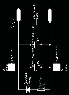
16 Printed circuit board connector wiring diagram Outdoor unit wiring diagram TO INDOOR UNIT FUSE2 CN4 CN10 CN15 CN14 CN13 BL BL CN6 CN9 CN8 CN7 CN1 CN3 CN2 PE AC-N AC-L CN11 CN10 CN23 AC-N AC-L CN8 CN9 Remark the dotted parts are optional for different unit. CN22 CN16 CN5 AMBIENT CN4CN3CN2 MAIN CONTROL BOARD CN26 CN24 CN20 CN19 CN18 CN17 TEMP.SENSOR TEMP.SENSOR SUCTION CN1 14 Domestic air conditioner
17 7. Functions and control Functions and control 7.1 Main functions and control specification The operation frequency of outdoor unit and its control The operation frequency control of compressor The operation frequency scope of compressor Mode Minimun operation frequency Maximun operation frequency Heating 36Hz 90 Hz Refrigeration 36Hz 80 Hz The starting of compressor When the compressor is started for the first time, it must be kept under the conditions of 58Hz,88Hz for one minute (the overheating protection of the outdoor unit air-blowing temperature, immediately decrease the frequency when the compressor is overflowing and releasing the pressure) then it can be operated towards the target frequency. When the machine runs normally, there s no such process. After starting the compressor for operation, the compressor should run according to the calculated frequency, and every determined frequency for protection should be prior to the calculated frequency The speeds of increasing or decreasing the frequency of the compressor The speed of increasing or decreasing the frequency rapidly HZ/second The speed of increasing or decreasing the frequency slowly HZ/10seconds The calculation of the compressor s frequency 1 The minimum/maximum frequency limitation A While refrigerating: F-MAX-r is the maximum operation frequency of the compressor; F-MIN-r is the minimum operation frequency of the compressor. B While heating: F-MAX-d is the maximum operation frequency of the compressor; F-MIN-d is the minimum operation frequency of the compressor. 2 The frequency limitation which is affected by the environment temperature. (Wh_c= environment temperature) Heating mode: Serial No. Temperature scope Frequency limitation 1 Wh_c<-12 Max_hz8 90HZ 2 Wh_c<-8 Max_hz7 90HZ 3 Wh_c<-2 Max_hz4 90HZ 4 Wh_c<5 Max_hz5 85HZ 5 Wh_c<10 Max_hz1 80HZ 6 Wh_c<17 Max_hz2 70HZ 7 Wh_c<20 Max_hz6 60HZ 8 Wh_c> 20 Max_hz3 45HZ Remarks: The above are the maximum frequency limitations of the complete appliance which are affected by the environment, and they have nothing to do with the ability of the indoor unit. 15 Domestic air conditioner
18 Functions and control Refrigeration/dehumidification mode: Serial No. Temperature scope Frequency limitation 1 Wh_c<28 Max_hz1 46HZ 2 Wh_c<32 Max_hz2 72HZ 3 Wh_c<40 Max_hz3 80HZ 4 Wh_c<48 Max_hz4 65HZ 5 Wh_c>=48 Max_hz5 50HZ Remarks: the above are not only the maximum frequency limitations of the complete appliance which are affected by the environment, but also the maximum ability limitation of the system. When the starting ability is not the maximum, its maximum frequency limitation is calculated by the following equations: The frequency limitation which is affected by the temperature and under the condition of actual ability the actual running system ability*the maximum frequency which is limited by the temperature and under the condition of maximum ability/the maximum designing ability of the system T= Ti*Pi / Pi ( Ti= Tst_i the setting temperature - Tnh_i the indoor environment temperature ; Pi i the ability of the indoor unit) Refrigeration/dehumidification: T < >=4 The percentage of the rated frequency P 50% 70% 100% 120% 140% Heating mode T < >=4 The percentage of the rated frequency P 50% 70% 100% 140% 160% The indoor setting airflow speed The percentage of the rated frequency Ki Breeze Low Medium High Strong Quiet Healthy airflow 65 70% 90% 100% 180% 65% 65% K= (Ki*Pi)/ Pi The calculation of the actual output frequency: when there is no healthy airflow: F= F-ED-*(rated frequency) P K When the healthy airflow has been set: F =F-ED-* P K airflow speed K healthy airflow Notes: When refrigerating, it is needed to satisfy F-MIN-d(compressor s Min_hz)< F<F-MAX-d(compressor s Max_hz) When heating, it is needed to satisfy F-MIN-r (compressor s Min_hz)< F<F-MAX-r (compressor s Max_hz) 16 Domestic air conditioner
19 Functions and control The outdoor fan control (Exchange fan) When the fan is changed among every airflow speed (including stop blowing), in order to avoid the airflow speed from skipping frequently, it must be kept under each mode for over 30 seconds, and then it can be changed to another mode (when refrigerating, the time is changed to 15 seconds) The outdoor fan control when refrigerating or dehumidifying After the compressor is started for 5 seconds, the outdoor fan is started at the medium speed at first, after 30 seconds, it begins to control the airflow speed according to the temperature conditions of the outdoor environment. The temperature of the outdoor air Ta The outdoor fan control when heating The temperature of the outdoor coil Te Airflow speed Ta 30 High 26 Ta<30 Keeping the speed 24 Ta<26 Medium 23 Ta<24 Keeping the speed 10 Ta<23 Low 5 Ta<10 Keeping the speed Ta<5 15 Te Low 15 >Te Stop The temperature of the outdoor air (Ta) Ta Ta<22 16 Ta<22 14 Ta<16 Ta<14 Airflow speed Low Keeping the speed Medium Keeping the speed High The control of the outdoor Electronic expansion valve (EEV) (09K series have no this function) In cooling mode, the EEV opening range is 90~480 steps. The EEV opening is 5 steps when unit is off. In heating mode, the EEV opening range is 60~480 steps. The EEV opening is 45 steps when unit is off. After outdoor unit is off, the EEV opening keep the current on for 5 s, then open the EEV completely for 2 minutes, then become 5 steps (cooling) or 45 steps (heating). The EEV opening will increase if SH (superheat degree) >0 while decrease if SH<0. Adjust frequency: If SH =0, 60s/ 1 step If SH 3,and SH=0, 10s/ 1 step. If 3 SH 0, 30s/ 1 step. SH= current SH- last SH SH= Ts (suction temp)-tc1 (indoor coil temp)-tsh (fixed data, depend on different models, -1~2) 17 Domestic air conditioner
20 Functions and control Four way control For the details of defrosting four-way valve control, see the defrosting process. Four way working in other ways: Under the mode of heating, open the four-way valve, when the compressor is not started or changed to non-heating mode, make sure the compressor is stoped for 2 minutes, and then close the four-way valve Protection function TTC high temperature-preventing protection Once the machine is started, it can run TTC(air-blowing temp) overheating protection of air-blowing, but air-blowing sensor malfunction must alarm after 4 minutes during which the compressor is started (during the course of self-detection, there s no such limitation) Sensor detection methods: 100 times (one cycle of procedure run is one time, and about 5ms, detection method for each time: continuously sampling for 8 times, then order them and take the mean value of the middle 2 values), take the mean value. TTC Abnormal stop 110 Decreasing the frequency rapidly 1HZ/second 100 Decreasing the frequency slowly (1HZ/10seconds) 98 The frequency doesn t change. 93 Increasing the frequency (1HZ/10second) 90 Increasing the frequency 1HZ/1second TTC>=110 lasts for 20 seconds. Overheating protection of air-blowing, alarm malfunction to the indoor, others don t last TC high temperature-preventing control of the indoor heating unit Tpg_indoor is the highest value of the effective indoor unit (start it and it is in accord with the running state). TC=indoor coil temp. The indoor heat exchanger sensor tests the temperature of the indoor heat exchanger. If the temperature is higher than 55, decrease the rotate speed of the compressor and do the high temperature-preventing protection of the indoor heat exchanger; if the temperature of the indoor heat exchanger is lower than 47, recover to the normal control. 18 Domestic air conditioner
21 Functions and control TC( ) The compressor stops Fgh_t1 65 Fgh_t1 2 Fgh_t2 2 N Decreasing the frequency rapidly Fgh_t2 59 P Decreasing the frequency slowly Fgh_t3 55 Fgh_t3 2 Fgh_t4 2 Q Prohibiting increasing the frequency Fgh_t4 51 R Increasing slowly Fgh_t5 47 Fgh_t5 2 Normal N Decreasing at the speed of 1HZ/1 second P Decreasing at the speed of 1Hz/10 seconds Q Continue to keep the last-time instruction cycle R Increasing at the speed of 1Hz/10seconds Remarks: the outdoor unit The control of preventing the over current of the compressor: During the starting process of the compressor, if the current of the compressor is greater than 11A for 3 seconds, stop the compressor and alarm, after 3 minutes, start it again, if such state appears 3 times in 20 minutes, stop the compressor and alarm, and confirm the malfunction. Then continue to run it only after the power is off. During the starting process of the compressor, if the AC current is greater than 8.5A, the frequency of the compressor decreases at the speed of 1HZ/second. During the starting process of the compressor, if the AC current is greater than 8A, the frequency of the compressor decreases at the speed of 0.1HZ/second. During the starting process of the compressor, if the AC current is greater than 7A, the frequency of the compressor increases at the prohibited speed. During the starting process of the compressor, if the AC current is greater than 6.5A, the frequency of the compressor increases at the speed of no faster than 0.1HZ/second The protection function of AC current: During the starting process of the compressor, if the AC current is greater than 12A for 3 seconds, stop the compressor and alarm, after 3 minutes, start it again, if such state appears 3 times in 20 minutes, stop the compressor and alarm, and confirm the malfunction. Then continue to run it only after the the power is off. During the starting process of the compressor, if the AC current is greater than 9A, the frequency of the compressor decreases at the speed of 1HZ/second. During the starting process of the compressor, if the AC current is greater than 8A, the frequency of the compressor decreases at the speed of 0.1HZ/second. During the starting process of the compressor, if the AC current is greater than 7A, the frequency of the compressor increases at the prohibited speed. During the starting process of the compressor, if the AC current is greater than 6.5A, the frequency of the compressor increases at the speed of no faster than 0.1HZ/second. Remarks: when the outdoor temperature is high, there s compensation for AC current protection. (1) When the outdoor environment temperature is higher than 40, AC current protection value 19 Domestic air conditioner
22 Functions and control decreases by 1A. (2) When the outdoor environment temperature is higher than 50, AC current protection value decreases by 2.5A Anti-freezing protection of the indoor heat exchanger When refrigerating/heating, prevent freezing. Tpg_indoor is the minimum value of the effective indoor unit (start it and it is in accord with the running state). 11 //ice_temp_3+5 ice_temp_3+3 9 Increasing slowly 8 //ice_temp_3+2 Keeping the frequency ice_temp_3 7 7 ice_temp_2 5 Decreasing slowly ice_temp_1 3 Decreasing rapidly ice_temp_1 0 Stop When Tpg_indoor ice_temp_1, the frequency of the compressor decreases at the speed of 1HZ/1second. When Tpg_indoor ice_temp_2, the frequency of the compressor decreases at the speed of 1HZ/10seconds. When Tpg_indoor begins to rise again, and ice_temp_2 Tpg_indoor ice_temp_3, the frequency of the compressor doesn t change. When ice_temp_3 Tpg_indoor ice_temp_3+3, the frequency of the compressor increases at the speed of 1HZ/10seconds. For example, Tpg_indoor 0 last for 2 minutes, and then the outdoor unit will stop, and report underload malfunction, but don t send malfunction report to the indoor. The compressor stops for more than 3 minutes, Tpg_indoor> ice_temp_3+2, the compressor recovers The frequency limitation of modification rate In the field which is controlled by high frequency, if the modification rate is not high enough, the control-driven chip will enter into weak magnetic control, this will help to relieve the problem of modification rate. If during the course of weak magnetic control, the modification rate is still not high enough, enter into the control of decreasing frequency until the alarm of modification rate is relieved Temperature protection of the outdoor refrigerating coil When the defrosting temperature and the sensor s temperature are higher than 65, the frequency of the compressor decreases 1hz/10seconds. Keep the frequency until it decreases to the lowest frequency. When the temperatures are lower than 65 and higher than 60, keep the frequency of 20 Domestic air conditioner
23 Functions and control the compressor. When the temperatures are lower than 60, relieve the defrosting temperature protection. 7.2 Value of Thermistor Ambient Sensor, Defrosting Sensor, Pipe sensor R25 =10K 3% B25 /50 =3700K 3% Temp.( ) Max.(K ) Normal(K ) Min.(K ) Tolerance( ) Domestic air conditioner
24 Functions and control Domestic air conditioner
25 Functions and control Domestic air conditioner
26 Functions and control Discharging Sensor R80 =50K 3% B25/80 =4450K 3% Temp.(( )) Max.(K ) Normal(K ) Min.(K ) Tolerance( ) Domestic air conditioner
27 Functions and control Domestic air conditioner
28 Functions and control Domestic air conditioner
29 Functions and control Domestic air conditioner
30 Functions and control Domestic air conditioner
31 8.Dimensional drawings Dimensional drawings unit:mm / Center of gravity unit:mm Domestic air conditioner

32 10 Service Diagnosis Service diagnosis 10.1 Caution for Diagnosis The operation lamp flashes when any of the following errors is detected. 1. When a protection device of the indoor or outdoor unit is activated or when the thermistor malfunctions, disabling equipment operation. 2. When a signal transmission error occurs between the indoor and outdoor units. In either case, conduct the diagnostic procedure described in the following pages. Parameter of primary electronic appliance name parameter picture Compressor Rated voltage: v Rated current:4.8a Rated frequency: 50/60HZ Fan motor Rated voltage: v Rated current:0.2a Rated frequency: 50/60HZ Reactor Rated voltage: v Rated current:10.5a Rated frequency: 50/60HZ 4-way valve Rated voltage: v Rated current:0.1a Rated frequency: 50/60HZ 30 Domestic air conditioner
33 Service diagnosis 10.2 Problem Symptoms and Measures Symptom None of the units operates Check Item Check the power supply. Check the indoor PCB Details of Measure Check to make sure that the rated voltage is supplied. Check to make sure that the indoor PCB is broken Operation sometimes stops. Check the power supply. A power failure of 2 to 10 cycles can stop air conditioner operation. Equipment operates but does not cool, or does not heat (only for heat pump) Check for faulty operation of the electronic expansion valve. Diagnosis by service port pressure and operating current. Set the units to cooling operation, and compare the temperatures of the liquid side connection pipes of the connection section among rooms to check the opening and closing operation of the electronic expansion valves of the individual units. Check for insufficient gas. Large operating noise and vibrations Check the installation condition. Check to make sure that the required spaces for installation (specified in the Technical Guide, etc.) are provided. 31 Domestic air conditioner
34 10.3 Error Codes and Description indoor display Service diagnosis Code indication Indoor and Outdoor Indoor Malfunction Outdoor Malfunction Indoor Outdoor Reference displaying fault description (LED1 flash Page panel code times) indication E7 15 Communication fault between indoor and outdoor units Page.44 E1 -- Room temperature sensor failure Page 33. E2 -- Heat-exchange sensor failure Page 33. E4 -- Indoor EEPROM error Page 34. E14 -- Indoor fan motor malfunction Page 35 F12 1 Outdoor EEPROM error Page.34 F1 2 The protection of IPM Page.38 F22 3 Overcurrent protection of AC electricity for the outdoor model Page.39 F3 4 Communication fault between the IPM and outdoor PCB Page.41 F19 6 Power voltage is too high or low Page.42 F4 8 Overheat protection for Discharge temperature Page.43 F21 10 Defrost temperature sensor failure Page 33. F7 11 Suction temperature sensor failure Page.33 F6 12 Ambient temperature sensor failure Page.33 F25 13 Discharge temperature sensor failure Page.33 F11 18 deviate from the normal for the compressor Page.46 F28 19 Loop of the station detect error Page.46 F2 24 Overcurrent of the compressor Page.39 F23 25 Overcurrent protection for single-phase of the compressor Page Domestic air conditioner
35 Thermistor or Related Abnormality Service diagnosis Indoor Display Outdoor display Method of Malfunction Detection Malfunction Decision Conditions Supposed Causes E1: Room temperature sensor failure E2: Heat-exchange sensor failure LED1 flash 10 times Defrost temperature sensor failure LED1 flash 11 times Suction temperature sensor failure LED1 flash 12 times Ambient temperature sensor failure LED1 flash 13 times Discharge temperature sensor failure The temperatures detected by the thermistors are used to determine thermistor errors When the thermistor input is more than 4.92V or less than 0.08V during compressor operation. Note: The values vary slightly in some models Faulty connector connection Faulty thermistor Faulty PCB Troubleshooting * Caution Be sure to turn off power switch before connect or disconnect connector, or else parts damage may be occurred. Check the connector connection. Is it normal? NO Correct the connection Yes Thermistor resistance check Is it normal? NO Replace the thermistor Yes Replace the indoor unit PCB Thermistor resistance check method: Remove the connector of the thermistor on the PCB, and measure the resistance of thermistor using tester.the relationship between normal temperature and resistance is shown in the value of indoor thermistor. 33 Domestic air conditioner
36 Service diagnosis EEPROM abnormal Indoor Display Indoor display E4: Indoor EEPROM error F12: Outdoor EEPROM error; Outdoor LED1 flash 1 times Method of Malfunction Detection The Data detected by the EEPROM are used to determine MCU Malfunction Decision Conditions When the data of EEPROM is error or the EEPROM is damaged Supposed Causes Faulty EEPROM data Faulty EEPROM Faulty PCB Troubleshooting * Caution Be sure to turn off power switch before connect or disconnect connector, or parts damage may be occurred. Replace the indoor or outdoor mainboard. 34 Domestic air conditioner
37 Service diagnosis Indoor AC fan motor malfunction Indoor Display E14 Method of Malfunction Detection Malfunction Decision Conditions Supposed Causes Troubleshooting The rotation speed detected by the Hall IC during fan motor operation is used to determine abnormal fan motor operation when the detected rotation feedback signal don t received in 2 minutes Operation halt due to breaking of wire inside the fan motor. Fan motor overheat protection Operation halt due to breaking of the fan motor lead wires Detection error due to faulty indoor unit PCB * Caution Be sure to turn off power switch before connect or disconnect connector, or else parts damage may be occurred. Check whether terminals on indoor pcb is well? Pull out the terminals on the indoor mainboard and reinsert them. Electrify the machine again and turn it on in the cooling operation, Measure voltage between the positions 1and 3 of Terminal CN5 on the indoor PCB the voltage is about vac check whether motor can run when turn on the unit Yes Measure whether there is voltage pulse (0-5VDC) between the positions middle wire and black wire of Terminal CN2 on the indoor PCB the indoor motor is damaged and need replace Is it ok? the indoor pcb is damaged and need replace 35 Domestic air conditioner
38 Service diagnosis Outdoor DC fan motor fault Outdoor display LED1 flash 9 times Method of Malfunction Detection Malfunction Decision Conditions DC fan motor is detected by checking the fan running condition and so on when the data of EEPROM is error or the EEPROM is damaged Supposed DC fan motor protection dues to the DC fan motor faulty Causes DC fan motor protection dues to faulty PCB Troubleshooting * Caution Be sure to turn off power switch before connect or disconnect connector, or parts damage may be occurred. 36 Domestic air conditioner
39 Service diagnosis Check whether Terminal on the outdoor mainboard is well inserted. Is it normal? NO Reinsert the terminals Yes Electrify the machine again and turn it on in the Cool state with the remote controller. check whether motor can run NO Yes Measure the voltage between 1 and 3 of the terminal of fan motor on the mainboard about DC310V, Measure the voltage between 3 and 4 of the terminal about Measure the voltage between 3 and 6 of the terminal about 0-5v. DC15V. Measure the voltage between 5 and 3 of the terminal about 1-6v. Is it normal? Yes Is it normal? N0 Yes N0 the motor of the outdoor unit is damaged and needs replacing. The mainboard of the outdoor unit is damaged and needs replacing 37 Domestic air conditioner
40 IPM protection Outdoor display: LED1 flash 2 times Service diagnosis Method of Malfunction Detection IPM protection is detected by checking the compressor running condition and so on Malfunction The system leads to IPM protection due to over current Decision The compressor faulty leads to IPM protection Conditions circuit component of IPM is broken and led to IPM protection Supposed IPM protection dues to the compressor faulty Causes IPM protection dues to faulty PCB of IPM module Compressor wiring disconnected Troubleshooting * Caution Be sure to turn off power switch before connect or disconnect connector, or else parts damage may be occurred. Electrify the machine again and turn it on with the remote controller,if malfunctions are reported before or upon the compressor being started up, IPM Module is damaged and needs replacing. Malfunction unsolved The compressor is started normally, but malfunctions are reported after it has run for some time. 1 The system may have been over or under charged with gas, which can be judged through the pressure of the measuring system. 2 The shaft of compressor is seized and the compressor needs replacing. 38 Domestic air conditioner
41 Over-current of the compressor Service diagnosis Outdoor Display: Method of Malfunction Detection Malfunction Decision Conditions Supposed Causes Troubleshooting LED1 flash 3 or 24 or 25 times The current of the compressor is too high when the IPM Module is damaged or the compressor is damaged. power supply voltage is too low or too high Faulty IPM Module Faulty compressor Faulty power supply * Caution Be sure to turn off power switch before connect or disconnect connector, or parts damage may be occurred. 39 Domestic air conditioner
42 Service diagnosis Electrify the machine again and turn it on with the remote controller, If malfunctions are reported before or upon the compressor being started up, YES IPM Module is damaged and needs replacing. NO The compressor is started normally, but malfunctions are reported after it has run for some time. Check the power supply is too low or too high NO Yes Repair the power supply NO The system may have been over or under charged with gas, which can be judged through the pressure of the measuring system. 40 Domestic air conditioner
43 The communication fault between IPM and outdoor PCB Outdoor display: LED1 flash 4 times Service diagnosis Method of Malfunction Detection Communication is detected by checking the IPM module and the outdoor PCB Malfunction The outdoor PCB broken leads to communication fault Decision The IPM module broken leads to communication fault Conditions Supposed The outdoor PCB is broken Causes The IPM module is broken Communication wiring disconnected Troubleshooting * Caution Be sure to turn off power switch before connect or disconnect connector, or else parts damage may be occurred. 1) Check whether Terminal CN23 and CN24 on the outdoor mainboard CN10 and CN11 on IPM module 2) Check whether the connected wire between IPM and outdoor Are they good? NO 1) Pull out and reinsert the terminals. 2) Replace connected wire YES Malfunction unsolved Electrify the machine again and turn it on, Check whether the voltage between 1 and 2 of Terminal CN23 is about DC5V, Check whether the voltage between2 and 3 of Terminal CN23 is about DC15V, YES Replace the outdoor IPM module with a new one. NO Replace the outdoor mainboard with a new one 41 Domestic air conditioner
44 Service diagnosis Power Supply Over or under voltage fault Outdoor display: LED1 flash 6 times The power supply is over voltage Method of Malfunction Detection Malfunction Decision Conditions An abnormal voltage rise or fall is detected by checking the specified voltage detection circuit. An voltage signal is fed from the voltage detection circuit to the microcomputer Supposed Supply voltage not as specified Causes the IPM module is broken the outdoor PCB is broken Troubleshooting * Caution Be sure to turn off power switch before connect or disconnect connector, or else parts damage may be occurred. Electrify the machine again and turn it on with the remote controller. Check whether the compressor is started normally Is it ok? Yes Maybe there is some disturbance No Test the outdoor power supply (+310VDC) with a multimeter. check whether the power is >150 V or <390V? Yes Change the IPM module ~230 is ok? NO Yes Change the IPM module NO This question may be caused by the power. Repair the power supply. 42 Domestic air conditioner
45 Service diagnosis Overheat Protection For Discharge Temperature Outdoor display: LED1 flash 8 times Method of Malfunction Detection Malfunction Decision Conditions The Discharge temperature control is checked with the temperature being detected by the Discharge pipe thermistor when the compressor discharge temperature is above 110 Supposed Electronic expansion valve defective Causes Faulty thermistor Faulty PCB Troubleshooting * Caution Be sure to turn off power switch before connect or disconnect connector, or else parts damage may be occurred. Electrify the machine again and turn it on with the remote controller, then measure the temperature at the exhaust temperature sensor of the compressor on the outdoor unit 1) The cryogen may have been leaked during The temperature exceeds 110 shortly after the machine starts up? YES installation, or there may be leakage in the piping system. 2) There may be other causes to make the exhaust temperature too high. NO Malfunctions occur after running for some time even though the measured temperature is below 110. Pull out the exhaust sensor and measure its resistance at standard temperatures according to the resistance-temperature table The results deviate much? YES The sensor is damaged. Replace the sensor with a new one. NO The outdoor mainboard is damaged and needs be replaced 43 Domestic air conditioner
46 Service diagnosis The communication fault between indoor and outdoor Indoor display outdoor display E7 LED1 flash 15 times Method of Malfunction Detection Communication is detected by checking the indoor PCB and the outdoor PCB. Malfunction The outdoor PCB broken leads to communication fault. Decision The indoor PCB broken leads to communication fault. Conditions Supposed Communication wiring disconnected. Causes The indoor PCB is broken. The outdoor PCB is broken. The Module PCB is broken. Troubleshooting * Caution Be sure to turn off power switch before connect or disconnect connector, or else parts damage may be occurred. Restart the a/c and it becomes normally. Yes The outdoor mainboard needs dehumidification. NO If starting up normally, but malfunction occurs again after a while NO The outdoor mainboard needs dedust. YES Check whether the linking cable between the indoor and outdoor is well connected or whether its core wires are well insulated. No 1. Reconnect the linking cable; 2. Replace the linking cable with new one. Yes A 44 Domestic air conditioner
47 Service diagnosis A Check the indoor mainboard. Yes Measure the voltage between Jumpers 3 and No 4 of IC1 on the indoor mainboard with a multimeter. Test the outdoor power supply (230VAC and +310VDC) with a multimeter. If the voltage is of a constant If 230VAC is available but 310DC not, the power module is damaged, replace it with a new one. value of 0V DCto5V DC YES If both 230VAC and 310DC are available, measure +12V(from7805) is available. NO The indoor mainboard is damaged; replace it with a new one. NO The outdoor mainboard is damaged; YES Replace them with a new one. Measure the AC voltage between positions 1 and 3 on the terminal of outdoor unit with a If the value is constant at about 30V, the multimeter. indoor mainboard is damaged, replace it with a new one. If the value varies between 0 and 80 VAC, the outdoor mainboard is damaged, replace it with a new one. The outdoor mainboard is damaged; replace it with a new one. 45 Domestic air conditioner
48 Service diagnosis Loss of synchronism detection Inverter side current detection is abnormal Outdoor Display Method of Malfunction Detection Malfunction Decision Conditions Supposed Causes Troubleshooting LED1 flash 18 times LED1 flash 19 times The position of the compressor rotor can not detected normally when the wiring of compressor is wrong or the connection is poor; or the compressor is damaged Faulty The wiring of compressor Faulty compressor Faulty PCB * Caution Be sure to turn off power switch before connect or disconnect connector, or parts damage may be occurred. Within 3 minutes after the machine is supplied with power and turned on with the remote controller, check whether the compressor can start up NO 1. The wiring of compressor is incorrect or the connection is poor; 2. The compressor is damaged YES At first, the compressor start up,soon the compressor stopped with the LED1 on the outdoor PCB blinks 1Hz 19/18 times YES IPM Module is damaged and needs replacing. Malfunction unsolved Maybe there is some disturbance the Malfunctions exist also, the compressor is damaged replace a new one 46 Domestic air conditioner
49 Service diagnosis High work-intense protection Outdoor display Method of Malfunction Detection Malfunction Decision Conditions LED1 flash 21 times High work-intense control is activated in the heating mode if the temperature being sensed by the heat exchanger thermistor exceeds the limit. Activated when the temperature being sensed by the heat exchanger rises above 65 twices in 30 minutes. Supposed Faulty electronic expansion valve Causes Dirty heat exchanger Faulty heat-exchange sensor Insufficient gas Troubleshooting * Caution Be sure to turn off power switch before connect or disconnect connector, or else parts damage may be occurred. Electrify the machine again and turn it on with the remote controller, check whether the wind temperature is below 65 The malfunction is reported after the machine has run for some time? YES 1 Check room temperature and pipe temperature sensor. 2 the temperature monitoring circuit of the indoor mainboard NO The indoor unit blows poorly due to blocked filters or poor condition of the fan? YES 1) Clean the filters 2) Reinstall the fan. NO Use some tools to measure the pressure of system 47 Domestic air conditioner
50 Performance and curves diagrams 11.Performence and curves diagrams 11.1 Cooling capacity-temperature curves indoor temp. performance curves cooling value-temerature table outdoor temp. DB/WB / / / / / / cooling capacity and indoor/outdoor temp.curves 6500 cooling capacity (W) indoor temp.(db/wb) 48 Domestic air conditioner
51 11.2 Cooling power consumption value- temperature curves Performance and curves diagrams indoor temp. performance curves power consumption value-temp.table outdoor temp. DB/WB / / / / / / power consumption and temp.curves 10 power consumption(w) indoor temp.(db/wb) 49 Domestic air conditioner
52 Performance and curves diagrams 11.3 Cooling discharge pressure curves performance curves cooling discharge pressure.table outdoor temp. (humidity 46%) indoor temp. DB/WB 21/15 27/19 35/ cooling discharge pressure and temp. curves 4000 discharge pressure (Kpa) /15 27/19 35/ outdoor temp.(db/wb) 50 Domestic air conditioner
53 Performance and curves diagrams 11.4 Cooling suction pressure curves performance curves cooling suction pressure.table outdoor temp. (humidity 46%) DB/WB 21/15 indoor temp. 27/19 35/ cooling suction pressure and temp.curves suction pressure (Kpa) outdoor temp.(db/wb) 51 Domestic air conditioner
54 Performance and curves diagrams 11.5 Heating capacity-temperature curves performance curves heating capacity and indoor/outdoor temp.table outdoor temp. DB/WB 10 indoor temp.(humidity 46%) / / / / / / heating capacity and indoor/outdoor temp.curves heating capacity(w) outdoor temp.(db/wb) 52 Domestic air conditioner
55 11.6 Heating power consumption value- temperature curves Performance and curves diagrams performance curves power consumption value-temp.table outdoor temp. DB/WB 10 indoor temp.(humidity 46%) / / / / / / heating capacity and indoor/outdoor temp.curves 2500 cooling capacity(w) /-8 2/1 7/6 12/11 18/16 24/20 outdoor temp.(db/wb) 53 Domestic air conditioner
56 Performance and curves diagrams 11.7 Heating discharge pressure curves performance curves heating discharge pressure.table outdoor temp indoor temp. DB/WB / / / / / / heating discharge pressure and temp. curves 4000 discharge pressure (Kpa) /-8 2/1 7/6 12/11 18/16 24/20 outdoor temp.(db/wb) 54 Domestic air conditioner
57 Performance and curves diagrams 11.8 Heating suction pressure curves performance curves heating suction pressure.table outdoor temp indoor temp. DB/WB / / / / / / heating suction pressure and temp. curves suction pressure (Kpa) /-8 2/1 7/6 12/11 18/16 24/20 outdoor temp.(db/wb) Domestic air conditioner


58 Circuit diagrams 12 Circuit diagrams 56 Domestic air conditioner


59 Circuit diagrams 57 Domestic air conditioner

60 Circuit diagrams Module board circuit diagram 58 Domestic air conditioner
SERVICE MANUAL. Wall Mounted Type DC Inverter WARNING. Haier Group Version V1 Date
 SERVICE MANUAL Wall Mounted Type DC Inverter Model No.U25BEFFRA WARNING This service information is designed for experienced repair technicians only and is not designed for use by the general public. It
SERVICE MANUAL. Wall Mounted Type ON/OFF T-Series HSU-07HUN103/R2-P WARNING. Haier Group Version V1 Date
 SERVICE MANUAL Wall Mounted Type ON/OFF T-Series Model No.1U07OR4EAA HSU-07HUN103/R2-P WARNING This service information is designed for experienced repair technicians only and is not designed for use by
SERVICE MANAUL. Wall Mounted Type DC Inverter FREE MATCH N-Series AS35NC2HRA
 SERVICE MANAUL Wall Mounted Type DC Inverter FREE MATCH N-Series Model No. AS26NC2HRA AS35NC2HRA WARNING This service information is designed for experienced repair technicians only and is not designed
SERVICE MANUAL. Wall Mounted Type DC Inverter FREE MATCH N-Series AS71NE1HRE
 SERVICE MANUAL Wall Mounted Type DC Inverter FREE MATCH N-Series Model No. AS53HE1HRA AS71NE1HRE WARNING This service information is designed for experienced repair technicians only and is not designed
SiBE04-808_C. Service Manual. Inverter Pair Wall Mounted Type G-Series. [Applied Models] Inverter Pair : Cooling Only Inverter Pair : Heat Pump
![SiBE04-808_C. Service Manual. Inverter Pair Wall Mounted Type G-Series. [Applied Models] Inverter Pair : Cooling Only Inverter Pair : Heat Pump](/thumbs/88/114609417.jpg "SiBE04-808_C. Service Manual. Inverter Pair Wall Mounted Type G-Series. [Applied Models] Inverter Pair : Cooling Only Inverter Pair : Heat Pump") Service Manual Inverter Pair Wall Mounted Type G-Series [Applied Models] Inverter Pair : Cooling Only Inverter Pair : Heat Pump Inverter Pair Wall Mounted Type G-Series Cooling Only Indoor Unit FTXS20G2V1B
Service Manual Inverter Pair Wall Mounted Type G-Series [Applied Models] Inverter Pair : Cooling Only Inverter Pair : Heat Pump Inverter Pair Wall Mounted Type G-Series Cooling Only Indoor Unit FTXS20G2V1B
SERVICE MANUAL. Model No. AS09/12GS2ERA 1U09/12BS1ERA AS09/12GS2ERA. Wall mounted Type WARNING. Haier Group. indoor unit and remote controller
 SERVICE MANUAL Order No. Wall mounted Type DC Inverter EM-Series Model No. AS09/12GS2ERA 1U09/12BS1ERA AS09/12GS2ERA indoor unit and remote controller 1U09/12BS1ERA outdoor unit WARNING This service information
SERVICE MANUAL. Wall Mounted Type DC Inverter
 SERVICE MANUAL Wall Mounted Type DC Inverter Model No. AS2TA2HRA WARNING This servic e informatio n is designed for experience d repai r technician s only and is not designe d for use by the genera l public.
Service Manual. Inverter Pair Floor / Ceiling Suspended Dual Type BA-Series. SiBE05-722_C
 Service Manual Inverter Pair Floor / Ceiling Suspended Dual Type BA-Series [Applied Models] Inverter Pair : Cooling Only Inverter Pair : Heat Pump Inverter Pair Floor / Ceiling Suspended Dual Type BA-Series
SERVICE MANUAL. Model No. HSU09VHJ(DB) Wall mounted Type DC Inverter EA-Series WARNING. Haier Group. Order No.AC1101S020V0
 Wall mounted Type DC Inverter EA-Series WARNING. Haier Group. Order No.AC1101S020V0") SERVICE MANUAL Order No.AC0S020V0 Wall mounted Type DC Inverter EA-Series Model No. HSU09VHJ(DB) WARNING This service information is designed for experienced repair technicians only and is not designed
SERVICE MANUAL Order No.AC0S020V0 Wall mounted Type DC Inverter EA-Series Model No. HSU09VHJ(DB) WARNING This service information is designed for experienced repair technicians only and is not designed
SiBE041010EA. Service Manual. Inverter Pair Wall Mounted Type J-Series. [Applied Models] Inverter Pair : Heat Pump
![SiBE041010EA. Service Manual. Inverter Pair Wall Mounted Type J-Series. [Applied Models] Inverter Pair : Heat Pump](/thumbs/88/115408421.jpg "SiBE041010EA. Service Manual. Inverter Pair Wall Mounted Type J-Series. [Applied Models] Inverter Pair : Heat Pump") Service Manual Inverter Pair Wall Mounted Type J-Series [Applied Models] Inverter Pair : Heat Pump Inverter Pair Wall Mounted Type J-Series Heat Pump Indoor Unit FTX20JV1B FTX25JV1B FTX35JV1B FTX20J2V1B
Service Manual Inverter Pair Wall Mounted Type J-Series [Applied Models] Inverter Pair : Heat Pump Inverter Pair Wall Mounted Type J-Series Heat Pump Indoor Unit FTX20JV1B FTX25JV1B FTX35JV1B FTX20J2V1B
SERVICE MANUAL. Inverter Wall Mounted Single Split. MODELS Cooling Only. Heatpump SM-5WM-Y-NA-B1
 SERVICE MANUAL Inverter Wall Mounted Single Split MODELS Cooling Only FTKB09AXVJU FTKB12AXVJU FTKB18AXVJU FTKB24AXVJU FTKN09AXVJU FTKN12AXVJU FTKN18AXVJU FTKN24AXVJU Heatpump FTXB09AXVJU FTXB12AXVJU FTXB18AXVJU
SERVICE MANUAL. Wall Mounted Type DC Inverter Model No. AS26TB1HRA AS35TB1HRA
 SERVICE MANUAL Wall Mounted Type DC Inverter Model No. AS26TB1HRA AS35TB1HRA WARNING This servic e informatio n is designed for experience d repai r technician s only and is not designe d for use by the
DC INVERTER MULTI-SYSTEM AIR CONDITIONER
 TECHNICAL & SERVICE MANUAL OUTDOOR UNIT : CU-3KE19NBU CU-4KE24NBU CU-4KE31NBU DC INVERTER MULTI-SYSTEM AIR CONDITIONER Capacity at 0V 19,100 BTU/h,200 BTU/h 30,600 BTU/h Outdoor Model No. CU-3KE19NBU CU-4KE24NBU
SiE Service Manual. Split System Air Conditioners SkyAir R-407C Super Inverter 70 D Series. [Applied Models] SkyAir : Inverter Heat Pump
![SiE Service Manual. Split System Air Conditioners SkyAir R-407C Super Inverter 70 D Series. [Applied Models] SkyAir : Inverter Heat Pump](/thumbs/85/91924488.jpg "SiE Service Manual. Split System Air Conditioners SkyAir R-407C Super Inverter 70 D Series. [Applied Models] SkyAir : Inverter Heat Pump") Service Manual Split System Air Conditioners SkyAir R-407C Super Inverter 70 D Series [Applied Models] SkyAir : Inverter Heat Pump Split-System Air Conditioners SkyAir Super Inverter 70 D Series 1. Introduction...
Service Manual Split System Air Conditioners SkyAir R-407C Super Inverter 70 D Series [Applied Models] SkyAir : Inverter Heat Pump Split-System Air Conditioners SkyAir Super Inverter 70 D Series 1. Introduction...
SiUS091601E Inverter Pair Wall Mounted Type FTX-N Series Floor Standing Type FVXS-N Series [Applied Models] Inverter Pair : Heat Pump
![SiUS091601E Inverter Pair Wall Mounted Type FTX-N Series Floor Standing Type FVXS-N Series [Applied Models] Inverter Pair : Heat Pump](/thumbs/71/66157661.jpg "SiUS091601E Inverter Pair Wall Mounted Type FTX-N Series Floor Standing Type FVXS-N Series [Applied Models] Inverter Pair : Heat Pump") Service Manual Inverter Pair Wall Mounted Type FTX-N Series Floor Standing Type FVXS-N Series [Applied Models] Inverter Pair : Heat Pump Inverter Pair Wall Mounted Type FTX-N Series Floor Standing Type
Service Manual Inverter Pair Wall Mounted Type FTX-N Series Floor Standing Type FVXS-N Series [Applied Models] Inverter Pair : Heat Pump Inverter Pair Wall Mounted Type FTX-N Series Floor Standing Type
Multi-Zone Technical Overview
 Multi-Zone Technical Overview Table of Contents Introduction... 2-11 Nomenclature... 2 Specifications...3-5 Safety Overview...6-7 Functions & Controls... 8-11 Outdoor Unit Technical Overview... 13-33 Components...
SiBE041525F. Service Manual. Inverter Pair Wall Mounted Type FTX/ATX-K Series. [Applicable Models] Inverter Pair: Heat Pump
![SiBE041525F. Service Manual. Inverter Pair Wall Mounted Type FTX/ATX-K Series. [Applicable Models] Inverter Pair: Heat Pump](/thumbs/92/110790777.jpg "SiBE041525F. Service Manual. Inverter Pair Wall Mounted Type FTX/ATX-K Series. [Applicable Models] Inverter Pair: Heat Pump") Service Manual Inverter Pair Wall Mounted Type FTX/ATX-K Series [Applicable Models] Inverter Pair: Heat Pump Inverter Pair Wall Mounted Type FTX/ATX-K Series Heat Pump Indoor Unit FTX20K(2)V1B FTX50K(M/2)V1B
Service Manual Inverter Pair Wall Mounted Type FTX/ATX-K Series [Applicable Models] Inverter Pair: Heat Pump Inverter Pair Wall Mounted Type FTX/ATX-K Series Heat Pump Indoor Unit FTX20K(2)V1B FTX50K(M/2)V1B
SERVICE MANUAL. Wall Mounted Type DC Inverter FREE MATCH N-Series
 SERVICE MANUAL Wall Mounted Type DC Inverter FREE MATCH N-Series Model No.AS09NSHRA-GU WARNING This service information is designed for experienced repair technicians only and is not designed for use by
Part 3 Troubleshooting
 Part Troubleshooting What is in this part? This part contains the following chapters: Chapter See page Troubleshooting 2 Error Codes: Hydro-box 7 Error Codes: Outdoor Units Error Codes: System Malfunctions
SERVICE MANUAL 42QHF009DS* 42QHF012DS* 42QHF018DS* 42QHF022DS* 38QUS009DS* 38QUS012DS* 38QUS018DS* 38QUS022DS* Indoor unit.
 SERVICE MANUAL Indoor unit Outdoor unit 42QHF009DS* 42QHF012DS* 42QHF018DS* 42QHF022DS* 38QUS009DS* 38QUS012DS* 38QUS018DS* 38QUS022DS* INDEX PART1 GENERAL INFORMATION PART2 ELECTRICAL DIAGRAM PART3 TROUBLE
SiBE041433E. Service Manual. Inverter Pair Wall Mounted Type FTXJ-L Series. [Applied Models] Inverter Pair : Heat Pump
![SiBE041433E. Service Manual. Inverter Pair Wall Mounted Type FTXJ-L Series. [Applied Models] Inverter Pair : Heat Pump](/thumbs/87/96681756.jpg "SiBE041433E. Service Manual. Inverter Pair Wall Mounted Type FTXJ-L Series. [Applied Models] Inverter Pair : Heat Pump") Service Manual Inverter Pair Wall Mounted Type FTXJ-L Series [Applied Models] Inverter Pair : Heat Pump Inverter Pair Wall Mounted Type FTXJ-L Series Heat Pump Indoor Unit FTXJ20LV1BW FTXJ20LV1BS FTXJ25LV1BW
Service Manual Inverter Pair Wall Mounted Type FTXJ-L Series [Applied Models] Inverter Pair : Heat Pump Inverter Pair Wall Mounted Type FTXJ-L Series Heat Pump Indoor Unit FTXJ20LV1BW FTXJ20LV1BS FTXJ25LV1BW
REYQ72-456TTJU REYQ72-456TYDN R-410A
 Service Manual REYQ72-456TTJU REYQ72-456TYDN R-410A Heat Recovery 60 Hz R-410A Heat Recovery 60 Hz ED Reference For items below, please refer to Engineering Data. No. Item ED No. Page Remarks 1 Specifications
Service Manual. Inverter Pair Floor Standing Type K-Series. Draft. SiBE [Applied Models] Inverter Pair : Heat Pump
![Service Manual. Inverter Pair Floor Standing Type K-Series. Draft. SiBE [Applied Models] Inverter Pair : Heat Pump](/thumbs/92/108387897.jpg "Service Manual. Inverter Pair Floor Standing Type K-Series. Draft. SiBE [Applied Models] Inverter Pair : Heat Pump") Warning Daikin products are manufactured for export to numerous countries throughout the world. Prior to purchase, please confirm with your local authorised importer, distributor and/or retailer whether
Warning Daikin products are manufactured for export to numerous countries throughout the world. Prior to purchase, please confirm with your local authorised importer, distributor and/or retailer whether
Ductless Split Air Conditioner
 Ductless Split Air Conditioner Service Manual Indoor AW09ESVHA AWESVHA AW8ESVHA AWESVHA Outdoor U09ESVHA UESVHA U8ESVHA UESVHA Design may vary by model number. Please read this manual before using the
Ductless Split Air Conditioner
 Ductless Split Air Conditioner Service Manual Indoor HSU09VHG(DB)-W HSUVHG(DB)-W HSU8VHH(DB)-W HSUVHG(DB)-W Outdoor HSU09VHG(DB)-G HSUVHG(DB)-G HSU8VHH(DB)-G HSUVHG(DB)-G Design may vary by model number.
TROUBLESHOOTING TROUBLESHOOTING. Indoor unit EEPROM parameter error. Indoor / outdoor units communication error. Zero-crossing signal detection error
 www.olmo-comfort.com TROUBLESHOOTING When below list for identification of error code occurs, please turn off air conditioner and disconnect power, and then contact the qualified professionals for service.
Service Manual. Inverter Pair. Floor / Ceiling Suspended Dual Type B-Series. [Applied Models] Inverter Pair : Cooling Only Inverter Pair : Heat Pump
![Service Manual. Inverter Pair. Floor / Ceiling Suspended Dual Type B-Series. [Applied Models] Inverter Pair : Cooling Only Inverter Pair : Heat Pump](/thumbs/89/100195066.jpg "Service Manual. Inverter Pair. Floor / Ceiling Suspended Dual Type B-Series. [Applied Models] Inverter Pair : Cooling Only Inverter Pair : Heat Pump") Service Manual Inverter Pair Floor / Ceiling Suspended Dual Type B-Series [Applied Models] Inverter Pair : Cooling Only Inverter Pair : Heat Pump Inverter Pair B-Series Cooling Only Indoor Unit Outdoor
Service Manual Inverter Pair Floor / Ceiling Suspended Dual Type B-Series [Applied Models] Inverter Pair : Cooling Only Inverter Pair : Heat Pump Inverter Pair B-Series Cooling Only Indoor Unit Outdoor
SiUS041638E. Service Manual. Inverter Pair Wall Mounted Type FTX-N Series. [Applied Models] Inverter Pair : Cooling Only Inverter Pair : Heat Pump
![SiUS041638E. Service Manual. Inverter Pair Wall Mounted Type FTX-N Series. [Applied Models] Inverter Pair : Cooling Only Inverter Pair : Heat Pump](/thumbs/76/73920531.jpg "SiUS041638E. Service Manual. Inverter Pair Wall Mounted Type FTX-N Series. [Applied Models] Inverter Pair : Cooling Only Inverter Pair : Heat Pump") Service Manual Inverter Pair Wall Mounted Type FTX-N Series [Applied Models] Inverter Pair : Cooling Only Inverter Pair : Heat Pump Inverter Pair Wall Mounted Type FTX-N Series Cooling Only Indoor Unit
Service Manual Inverter Pair Wall Mounted Type FTX-N Series [Applied Models] Inverter Pair : Cooling Only Inverter Pair : Heat Pump Inverter Pair Wall Mounted Type FTX-N Series Cooling Only Indoor Unit
SiUS04-924_A. Service Manual. Inverter Pair Wall Mounted Type H-Series. [Applied Models] Inverter Pair : Cooling Only Inverter Pair : Heat Pump
![SiUS04-924_A. Service Manual. Inverter Pair Wall Mounted Type H-Series. [Applied Models] Inverter Pair : Cooling Only Inverter Pair : Heat Pump](/thumbs/71/65602543.jpg "SiUS04-924_A. Service Manual. Inverter Pair Wall Mounted Type H-Series. [Applied Models] Inverter Pair : Cooling Only Inverter Pair : Heat Pump") Service Manual Inverter Pair Wall Mounted Type H-Series [Applied Models] Inverter Pair : Cooling Only Inverter Pair : Heat Pump Inverter Pair Wall Mounted Type H-Series Cooling Only Indoor Unit FTXS30HVJU
Service Manual Inverter Pair Wall Mounted Type H-Series [Applied Models] Inverter Pair : Cooling Only Inverter Pair : Heat Pump Inverter Pair Wall Mounted Type H-Series Cooling Only Indoor Unit FTXS30HVJU
SiE Service Manual. RXYQ5-48MAY1 R410A Heat Pump 50Hz
 SiE39-40 Service Manual RXYQ5-48MAY1 R410A Heat Pump 50Hz SiE39-40 R410A Heat Pump 50Hz 1 Introduction vi 11 Safety Cautions vi 12 PREFACE x Part 1 General Information 1 1 Model Names of Indoor/Outdoor
DC INVERTER MULTI-SYSTEM AIR CONDITIONER
 TECHNICAL & SERVICE MANUAL OUTDOOR UNIT : CLM97 CLM7 CLM7 FILE NO. Destination: North America DC INVERTER MULTI-SYSTEM AIR CONDITIONER Capacity at 0V 9,700 BTU/h,00 BTU/h 0,600 BTU/h Outdoor Model No.
Inverter Pair FTK(X)-J / RK(X)-J Series
-J / RK(X)-J Series") Si-86.book Page i Friday, June 23, 2000 10:26 AM Inverter Pair FTK(X)-J / RK(X)-J Series Cooling Only Indoor Unit FTK25JV1NB FTK35JV1NB Outdoor Unit RK25JV1NB RK35JV1NB Heat Pump Indoor Unit FTX25JV1NB
Si-86.book Page i Friday, June 23, 2000 10:26 AM Inverter Pair FTK(X)-J / RK(X)-J Series Cooling Only Indoor Unit FTK25JV1NB FTK35JV1NB Outdoor Unit RK25JV1NB RK35JV1NB Heat Pump Indoor Unit FTX25JV1NB
YC ON-OFF SERIES. Service Manual
 YC ON-OFF SERIES Service Manual CONTENTS 1. Precaution... 3 1.1 Safety Precaution... 3 1.2 Warning... 3 2. Model Lists... 6 3. Dimension... 7 3.1 Indoor Unit... 7 3.2 Outdoor Unit... 11 4. Refrigerant
Service manual. MIV V4+ Mini
 DM12-01.01.05en Service manual MIV V4+ Mini DC INVERTER R410A (~220V, 50Hz, 1Ph) MVUH80A-VA1 Contents Part 1 General Information... 1 Part 2 Outdoor Units... 6 Part 3 Installation... 44 DM12-01.01.05en
SERVICE MANUAL MUZ-DM25VA - E1, ER1, ET1 MUZ-DM35VA - E1, ER1, ET1 OUTDOOR UNIT. No. OBH751. Models HFC R410A
 OUTDOOR UNIT SERVICE MANUAL HFC utilized R410A. Models MUZ-DM25VA - E1, ER1, ET1 MUZ-DM35VA - E1, ER1, ET1 Indoor unit service manual MSZ-DM VA Series (OBH750) CONTENTS 1. TECHNICAL CHANGES 2 2. PART NAMES
Warning: 230V / 1ph / 50Hz V / 3ph / 50Hz. Remarks: Make sure that you have enough power. (See page 15 Cable table)
") 1 2 Warning: - Do not place your hand or any other objects into the air outlet and fan. It could damage the heat pump and cause injuries; - In case of any abnormality with the heat pump, cut off the power
1 2 Warning: - Do not place your hand or any other objects into the air outlet and fan. It could damage the heat pump and cause injuries; - In case of any abnormality with the heat pump, cut off the power
SERVICE MANUAL OUTDOOR UNIT MUZ-FH06NAH MUZ-FH09NAH MUZ-FH06NA MUZ-FH09NA MUZ-FH09NA - 1 MUZ-FH09NAH - 1 MUZ-FH12NA MUZ-FH12NAH
 Revision D: Capacity corrections have been corrected [7-1. 2), 3)]. OBH684 REVISED EDITION-C is void. OUTDOOR UNIT SERVICE MANUAL HFC utilized R410A. OBH684 REVISED EDITION-D Models MUZ-FH06NA MUZ-FH09NA
SERVICE MANUAL. No. OBH747 REVISED EDITION-A. Models HFC
 Revision A: MUZ-HM09/12NA- U8, MUZ-HM09/12NA2- U8, MUZ-HM15/18NA- U1, MUZ-HM15/18NA2- U1 and MUZ-HM24NA2- U1 have been added. Please void OBH747. OUTDOOR INDOOR UNIT UNIT SERVICE MANUAL HFC utilized R410A.
DC INVERTER SPLIT SYSTEM AIR CONDITIONER
 AIR CONDITIONER TECHNICAL & SERVICE MANUAL KS1872 + C1872 + CL1872 KS2472 + C2472 + CL2472 FILE NO. Destination: North America DC INVERTER SPLIT SYSTEM AIR CONDITIONER Indoor Model No. KS1872 KS2472 Product
AUTO COOL DRY FAN SPEED AIR SWING OFF ON TIMER TIMER OFF/ON FAN SPEED MODE TEMP AIR SWING TIMER ON SET OFF CANCEL AC RC SET CHECK CLOCK RESET
 AUTO COOL DRY MODE TIMER ON OFF TIMER OFF/ON TEMP ON TIMER FAN SPEED AIR SWING SET 1 2 3 FAN SPEED AIR SWING OFF CANCEL AC RC SET CHECK CLOCK RESET Order No: PAPAMY1611008CE Indoor Unit CS-MPS9SKH CS-MPS12SKH
3.2 E1 Outdoor Unit PCB Abnormality E4 Actuation of Low Pressure Sensor E5 Compressor Motor Lock 3 52
 Error Codes: Outdoor Units Error Codes: Outdoor Units Part. What Is in This Chapter? Introduction Overview In the first stage of the troubleshooting sequence, it is important to correctly interpret the
SERVICE MANUAL MUY-GL24NA - U1. No. OBH733. Models HFC. Revision B: REVISED EDITION-B R410A
 Revision B: MUZ-GL09NA- U8 and MUZ-GL09NAH- U8 have been added. Please void OBH733 REVISED EDITION-A. OUTDOOR INDOOR UNIT UNIT SERVICE MANUAL HFC utilized R410A. OBH733 REVISED EDITION-B Models MUZ-GL09NA
TECENICAL DATA. Model No. HSU-09HEA03/R2(DB)-I HSU-12HEA03/R2(DB)-I HSU-18HEA03/R2(DB)-I HSU-24HEA03/R2(DB)-I. Wall mounted Type. DC Inverter E-Series
-I HSU-12HEA03/R2(DB)-I HSU-18HEA03/R2(DB)-I HSU-24HEA03/R2(DB)-I. Wall mounted Type. DC Inverter E-Series") TECENICAL DATA Order No.AC0902T003V0 Wall mounted Type DC Inverter E-Series Model No. HSU-09HEA03/R2(DB)-I HSU-12HEA03/R2(DB)-I HSU-18HEA03/R2(DB)-I HSU-24HEA03/R2(DB)-I 9K 12K 18K 24K 09K 12K 18K WARNING
TECENICAL DATA Order No.AC0902T003V0 Wall mounted Type DC Inverter E-Series Model No. HSU-09HEA03/R2(DB)-I HSU-12HEA03/R2(DB)-I HSU-18HEA03/R2(DB)-I HSU-24HEA03/R2(DB)-I 9K 12K 18K 24K 09K 12K 18K WARNING
VMI-1102-A SERVICE MANUAL AIRCONDITIONER DC INVERTER MULTI TYPE MSV1I-09HRDN1-M TAS-09MVHN TAS-12MVHN INDOOR VERTU DC INVERTER MULTI SERIES
 VMI-1102-A SERVICE MANUAL AIRCONDITIONER DC INVERTER MULTI TYPE MSV1I-09HRDN1-M TAS-09MVHN TAS-12MVHN INDOOR VERTU DC INVERTER MULTI SERIES CONTENTS 1. Precaution... 1 1.1 Safety Precaution...1 1.2 Warning...1
SPLIT TYPE ROOM AIR CONDITIONER. WALL MOUNTEDtype INVERTER. Models Indoor unit Outdoor unit AOU 9RLFW1 AOU12RLFW1 ASU 9RLF1 ASU12RLF1 R410A
 SERVICE INSTRUCTION SPLIT TYPE ROOM AIR CONDITIONER WALL MOUNTEDtype INVERTER Models Indoor unit Outdoor unit ASU 9RLF ASURLF AOU 9RLFW AOURLFW R40A CONTENTS. DESCRIPTION OF EACH CONTROL OPERATION. COOLING
Inverter Pair Wall Mounted Type H-Series
 Inverter Pair Wall Mounted Type H-Series [Applied Models] Inverter Pair : Heat Pump Inverter Pair H-Series Heat Pump Indoor Units FTXS30HVJU FTXS36HVJU Outdoor Units RXS30HVJU RXS36HVJU Inverter Pair H-Series
DC INVERTER MULTI-SYSTEM AIR CONDITIONER Capacity 7,500BTU / h 9,000BTU / h 11,900BTU / h 17,500BTU / h 24,200BTU / h
 AIR CONDITIONER AIR CONDITIONER TECHNICAL & SERVICE MANUAL INDOOR UNIT : CS-MKS7NKU CS-MKS9NKU CS-MKS12NKU CS-MKS18NKU CS-MKS24NKU DC INVERTER MULTI-SYSTEM AIR CONDITIONER Capacity 7,500BTU / h 9,000BTU
R410A. WALL MOUNTEDtype INVERTER SPLIT TYPE ROOM AIR CONDITIONER. Models Indoor unit Outdoor unit AOYG07LEC AOYG09LEC AOYG12LEC AOYG14LEC
 SERVICE INSTRUCTION SPLIT TYPE ROOM AIR CONDITIONER WALL MOUNTEDtype INVERTER Models Indoor unit Outdoor unit ASYG07LECA ASYG09LECA ASYG12LECA ASYG14LECA AOYG07LEC AOYG09LEC AOYG12LEC AOYG14LEC R410A CONTENTS
DC INVERTER SPLIT SYSTEM AIR CONDITIONER
 AIR CONDITIONER TECHNICAL & SERVICE MANUAL CS-KE30NKU + CU-KE30NKU CS-KE36NKU + CU-KE36NKU DC INVERTER SPLIT SYSTEM AIR CONDITIONER Indoor Model No. CS-KE30NKU CS-KE36NKU Product Code No. 1 852 360 88
Service Manual. Room Air Conditioner Split Wall-Mounted Type. Applies to: HSG-09HRN1 HSG-12HRN1 HSG-18HRN1 HSG-24HRN1
 Service Manual Room Air Conditioner Split Wall-Mounted Type Applies to: HSG-09CRN1 HSG-12CRN1 HSG-18CRN1 HSG-24CRN1 HSG-09HRN1 HSG-12HRN1 HSG-18HRN1 HSG-24HRN1 NOTE: Please read this first before servicing
SiUS181631EA. Service Manual. Multi-Split Type Air Conditioners RMXS-L Series. [Applied Models] Inverter Multi : Heat Pump
![SiUS181631EA. Service Manual. Multi-Split Type Air Conditioners RMXS-L Series. [Applied Models] Inverter Multi : Heat Pump](/thumbs/86/94613913.jpg "SiUS181631EA. Service Manual. Multi-Split Type Air Conditioners RMXS-L Series. [Applied Models] Inverter Multi : Heat Pump") Service Manual Multi-Split Type Air Conditioners RMXS-L Series [Applied Models] Inverter Multi : Heat Pump Multi-Split Type Air Conditioners RMXS-L Series Heat Pump Outdoor Unit RMXS48LVJU Branch Provider
Service Manual Multi-Split Type Air Conditioners RMXS-L Series [Applied Models] Inverter Multi : Heat Pump Multi-Split Type Air Conditioners RMXS-L Series Heat Pump Outdoor Unit RMXS48LVJU Branch Provider
SERVICE MANUAL MUZ-FH25VE MUZ-FH35VE MUZ-FH50VE OUTDOOR UNIT. No. OBH624. Models HFC. Revision A: MUZ-FH50VE- E1 has been added. Please void OBH624.
 SPLIT-TYPE AIR CONDITIONERS Revision A: MUZ-FH50VE- E1 has been added. Please void OBH624. OUTDOOR UNIT SERVICE MANUAL HFC utilized R410A. OBH624 REVISED EDITION-A Models MUZ-FH25VE MUZ-FH35VE MUZ-FH50VE
 Indoor AW09TEVHA AWTEVHA AW8TEVHA AW4TEVHA Out door U09TEVHA UTEVHA U8TEVHA U4TEVHA.. WVVAC. Table of Contents...... 7...... 9... 5....... 4... 55 PAGE [This page intentionally left blank.] Introduction
SERVICE MANUAL K LIGHT COMMERCIAL
 SERVICE MANUAL 36 48 60K LIGHT COMMERCIAL Cassette indoor unit Under-ceiling indoor unit Ducted indoor unit 42QTD036DS* 42QTD048DS* 42QTD060DS* 42QZL036DS* 42QZL048DS* 42QZL060DS* 42QSM036DS* 42QSM048DS*
SERVICE INSTRUCTION R410A. WALL MOUNTEDtype INVERTER SPLIT TYPE ROOM AIR CONDITIONER. Models Indoor unit Outdoor unit AOU9RLS2H AOU12RLS2H AOU15RLS2H
 SERVICE INSTRUCTION SPLIT TYPE ROOM AIR CONDITIONER WALL MOUNTEDtype INVERTER Models Indoor unit Outdoor unit ASU9RLS ASURLS ASU5RLS AOU9RLSH AOURLSH AOU5RLSH R40A CONTENTS. DESCRIPTION OF EACH CONTROL
TECHNICAL & SERVICE MANUAL WINDOW TYPE AIR CONDITIONER SA 183A FILE NO. SA 183A REFERENCE NO. SM Destination Australia SA-183A
 TECHNICAL & SERVICE MANUAL SA 183A FILE NO. WINDOW TYPE AIR CONDITIONER Model No. Product Code No. SA-183A 1 851 006 96 Destination Australia SA 183A REFERENCE NO. SM700514 IMPORTANT! Please Read Before
SERVICE MANUAL MUFZ-KJ50VE - E1, E2, ER1, ER2, ET1, ET2 MUFZ-KJ35VE OUTDOOR UNIT. No. OBH667. Models HFC
 Revision D: MUFZ-KJ25VE - E2, ER2, ET2, MUFZ- KJ35VE - E2, ER2, ET2 and MUFZ- KJ50VE - E2, ER2, ET2 have been added. Please void OBH667 REVISED EDITION-C. OUTDOOR UNIT SERVICE MANUAL HFC utilized R410A.
Inverter K Series Series
 TOC.fm Page i Tuesday, April 11, 2000 2:19 PM Inverter K Series Series 1. Introduction...v 1.1 Safety Cautions... v 1.2 PREFACE...ix Part1 General Information Inverter K Series...1 1. Outline...2 1.1 System
Owner s Manual Window Air Conditioner
 Owner s Manual Window Air Conditioner G17-5MCVWAC1 G16-5MCVWAC Write the model and serial numbers below for your records: Model # Serial # Date Purchased Please read the entire manual carefully to ensure
R410A. WALL MOUNTEDtype INVERTER SPLIT TYPE ROOM AIR CONDITIONER. Models Indoor unit Outdoor unit AO*G09LTCN AO*G12LTCN AO*G14LTCN
 SERVICE INSTRUCTION SPLIT TYPE ROOM AIR CONDITIONER WALL MOUNTEDtype INVERTER Models Indoor unit Outdoor unit AS*G09LTCB AS*GLTCB AS*G4LTCB AO*G09LTCN AO*GLTCN AO*G4LTCN R40A CONTENTS. DESCRIPTION OF EACH
SERVICE MANUAL. Refrigerator MODEL: HA10TG31SW HA10TG31SB HA10TG31SS WARNING. Haier Group
 Order. Ref1409S001V0 Refrigerator MODEL: HA10TG31SW HA10TG31SB HA10TG31SS WARNING This service information is designed for experienced repair technicians only and is not designed for use by the general
DC INVERTER MULTI-SYSTEM AIR CONDITIONER
 TECHNICAL & SERVICE MANUAL INDOOR UNIT : CS-MKE9NB4U & CZ-18BT1U CS-MKE12NB4U & CZ-18BT1U CS-KE18NB4UW & CZ-18BT1U DC INVERTER MULTI-SYSTEM AIR CONDITIONER Capacity 9,000BTU / h 11,900BTU / h 17,500BTU
SERVICE MANUAL UNI SPLIT SERIES. ASC-xxBI, ASD-xxBI, ASF-xxBI, ASGE-xxBI, ASGE-xxBI-3
 EN SERVICE MANUAL UNI SPLIT SERIES ASC-xxBI, ASD-xxBI, ASF-xxBI, ASGE-xxBI, ASGE-xxBI-3 Original instructions IMPORTANT NOTE: Read this manual carefully before installing or operating your new air conditioning
DC INVERTER SPLIT SYSTEM AIR CONDITIONER
 TECHNICAL & SERVICE MANUAL KHS308 + CH308 KHS368 + CH368 FILE NO. Destination: North America DC INVERTER SPLIT SYSTEM AIR CONDITIONER Indoor Model No. KHS308 KHS368 Product Code No. 85 354 8 85 354 9 Outdoor
SERVICE INSTRUCTION R410A. WALL MOUNTEDtype INVERTER SPLIT TYPE ROOM AIR CONDITIONER. Models Indoor unit Outdoor unit AO*G24LFL AO*G24LFCC AO*G30LFT
 SERVICE INSTRUCTION SPLIT TYPE ROOM AIR CONDITIONER WALL MOUNTEDtype INVERTER Models Indoor unit Outdoor unit AS*G4LFCA AS*G4LFCC AS*G0LFCA AO*G4LFL AO*G4LFCC AO*G0LFT R40A CONTENTS. DESCRIPTION OF EACH
Inverter Split-type Room Air Conditioner
 OWNER S MANUAL Inverter Split-type Room Air Conditioner Please read the operating instructions and safety precautions carefully and thoroughly before installing and operating your room air conditioner.
Part 5. Troubleshooting. 1. Normal Air Conditioner Phenomenon Air Conditioner Protection in Common
 Part 5 1. Normal Air Conditioner Phenomenon... 1611 2. Air Conditioner Protection in Common... 1611 3. Malfunction Code and... 162 160 1. Normal Air Conditioner Phenomenon 1.1 When outdoor unit appears
DuctlessAire ES Series. Service Manual 2016 ABSSA-B4-1601
 DuctlessAire ES Series Service Manual 2016 ABSSA-B4-1601 CONTENTS 1. Precaution... 1 1.1 Safety Precaution... 1 1.2 Warning... 1 2. Model list... 4 3. Dimension... 5 3.1 Indoor Unit... 5 3.2 Outdoor Unit...
TECHNICAL DATA & SERVICE MANUAL
 TECHNICAL DATA & SERVICE MANUAL OUTDOOR UNIT:. TRIAL SPLIT SYSTEM AIR CONDITIONER Model No. Product Code No. 38.7107.102. 0.8180.611.02 09/2012 IMPORTANT! Please read before installation This air conditioning
SERVICE MANUAL MUZ-FH25VE MUZ-FH35VE MUZ-FH50VE OUTDOOR UNIT. No. OBH624 REVISED EDITION-E. Models HFC
 Revision E: MUZ-FH25VE- E4, ER4, ET3, MUZ- FH35VE- E3, ER3, ET3 and MUZ- FH50VE- E2, ER2, ET2 have been added. Please void OBH624 REVISED EDITION-D. OUTDOOR UNIT SERVICE MANUAL HFC utilized R410A. OBH624
DUCTED AIR CONDITIONER. Owner s Manual. KD Series KD24. Kaden Owner s Manual 1
 DUCTED AIR CONDITIONER Owner s Manual KD Series KD24 Kaden Owner s Manual 1 Table of Contents 1. Safety Precautions 4 2. Indoor Unit Parts and Major Functions 6 3. Care and Maintenance 8 4. Troubleshooting
SERVICE MANUAL. Wall Mounted Type DC Inverter FREE MATCH N-Series
 SERVICE MANUAL Wall Mounted Type DC Inverter FREE MATCH N-Series Model No. AS5BS4HRA WARNING This service information is designed for experienced repair technicians only and is not designed for use by
TECHNICAL & SERVICE MANUAL WINDOW TYPE AIR CONDITIONER SA 123A FILE NO. SA 123A REFERENCE NO. SM700513
 TECHNICAL & SERVICE MANUAL SA 123A FILE NO. WINDOW TYPE AIR CONDITIONER Model No. Product Code No. Destination SA-123A 1 851 006 95 Australia SA 123A REFERENCE NO. SM700513 IMPORTANT! Please Read Before
Troubleshooting & Reference
 Troubleshooting & Reference Error Code Descriptions Description of Error Codes - 9, 12 MBH code malfunction Error Display Repair Method 1 Storage slug (EEPROM) 2 Indoor PCB malfunction 3 Anti-freezing
SERVICE MANUAL MUZ-HJ50VA - E1, E2, ER1, ER2, ET1, ET2 MUZ-HJ35VA - E1, E3, ER1, ER3, ET1, ET2
 Revision F: "How to check miswiring and serial signal error" has been corrected (11-5. M ). OBH648 REVISED EDITION-E is void. OUTDOOR UNIT SERVICE MANUAL HFC utilized R410A. OBH648 REVISED EDITION-F Models
TECHNICAL & SERVICE MANUAL. Ceiling Concealed
 STAND BY DEFROST CHECK CLOCK ON OFF NOT AVAILABLE FILTER CHECK MODE TEST RUN FUNCTION SPLIT-TYPE, HEAT PUMP AIR CONDITIONERS TECHNICAL & SERVICE MANUAL Series SEZ Ceiling Concealed R40A.OC0 REVISED EDITION-A
TECHNICAL DATA & SERVICE MANUAL
 TECHNICAL DATA & SERVICE MANUAL OUTDOOR UNIT: GRF188R5TAA GRF228R5TAA GRF228R7TAA SPLIT SYSTEM AIR CONDITIONER Model No. Product Code No. GRF188R5TAA 38.7107.083 GRF228R5TAA 38.7107.084 GRF228R7TAA 38.7107.085
Owner s Manual Super-Slim Four-Way Cassette
 CASSETTE- TYPE AIR CONDITIONER Owner s Manual Super-Slim Four-Way Cassette IMPORTANT NOTE: Read this manual carefully before installing or operating your new air conditioning unit. Make sure to save this
Bosch Split-Type Ductless Air Conditioner / Heat Pump
 Bosch Split-Type Ductless Air Conditioner / Heat Pump Climate 5000 AA Series Service Manual 2 Bosch Climate 5000 AA Series Split Type Ductless Air Conditioner / Heat Pump Service Manual Data subject to
SERVICE INSTRUCTION R410A. WALL MOUNTEDtype SPLIT TYPE ROOM AIR CONDITIONER INVERTER. Models Indoor unit Outdoor unit AO* R09LECN AO* R12LECN
 SERVICE INSTRUCTION SPLIT TYPE ROOM AIR CONDITIONER WALL MOUNTEDtype INVERTER Models Indoor unit Outdoor unit AS* A09LEC AS* A12LEC AO* R09LECN AO* R12LECN R410A CONTENTS 1. DESCRIPTION OF EACH CONTROL
COMPACT PORTABLE AIR CONDITIONER USER MANUAL
 COMPACT PORTABLE AIR CONDITIONER USER MANUAL Thank you for choosing ElectriQ Please read this user manual before using this innovative Air Conditioner and keep it safe for future reference. Visit our page
Service Manual CAUTION ! WARNING SAFETY CONSIDERATIONS INTRODUCTION. 38MA*R Outdoor Unit Single Zone Ductless System Sizes 09 to 36
 38MA*R Outdoor Unit Single Zone Ductless System Sizes 09 to 36 Service Manual TABLE OF CONTENTS PAGE SAFETY CONSIDERATIONS... 1 INTRODUCTION... 1 MODEL / SERIAL NUMBER NOMENCLATURES... 2 SPECIFICATIONS...
TECHNICAL & SERVICE MANUAL WINDOW TYPE AIR CONDITIONER SA 93AH FILE NO. SA 93AH REFERENCE NO. SM700510
 TECHNICAL & SERVICE MANUAL SA 93AH FILE NO. WINDOW TYPE AIR CONDITIONER Model No. Product Code No. Destination SA-93AH 1 851 006 97 Australia SA 93AH REFERENCE NO. SM700510 IMPORTANT! Please Read Before
The breaker trips at once when it is set to ON. The breaker trips in few minutes when it is set to ON.
 Trip of breaker or The breaker trips at once when it is set to O. Measure insulation resistance to ground to see if there is any leakage. Air conditioner can not start up blow of fuse The air conditioner
SERVICE MANUAL OUTDOOR UNIT. No. OBH530. Models MU-GE50VB- E1 MUH-GE50VB- E1 HFC SPLIT-TYPE AIR CONDITIONERS R410A
 SPLIT-TYPE AIR CONDITIONERS OUTDOOR UNIT SERVICE MANUAL HFC utilized R410A. OBH530 Models MU-GE50VB- E1 - E1 Indoor unit service manual MS/MSH-GE VB Series (OBH529) CONTENTS 1. TECHNICAL CHANGES 2 2. PART
SERVICE MANUAL MUZ-SF25VE MUZ-SF25VEH MUZ-SF35VE MUZ-SF35VEH MUZ-SF42VE MUZ-SF42VEH MUZ-SF50VE MUZ-SF50VEH OUTDOOR UNIT. No. OBH629 REVISED EDITION-E
 Revision E: The descriptions of the expansion valve coil have been corrected. (11-4.) Please void OBH629 REVISED EDITION-D. OUTDOOR UNIT SERVICE MANUAL HFC utilized R410A. OBH629 REVISED EDITION-E Models
SERVICE INSTRUCTION R410A. SPLIT TYPE ROOM AIR CONDITIONER Cassette type Duct type Ceiling type INVERTER AO* G45LETL AO* G54LETL
 SPLIT TYPE ROOM AIR CONDITIONER Cassette type Duct type Ceiling type INVERTER SERVICE INSTRUCTION Models Indoor unit AU* G45LRLA AR* G45LMLA AR* G45LHTA AB* G45LRTA Outdoor unit AO* G45LETL AO* G54LETL
Owner s Manual. Middle Static Pressure Duct Type MEU-18MPH2 MEU-24MPH2 MEU-36MPL2 MEU-48MPL2 MIDDLE STATIC PRESSURE DUCT TYPE AIR CONDITIONER
 MIDDLE STATIC PRESSURE DUCT TYPE AIR CONDITIONER Owner s Manual Middle Static Pressure Duct Type MEU-18MPH2 MEU-24MPH2 MEU-36MPL2 MEU-48MPL2 IMPORTANT NOTE: Read this manual carefully before installing
MODELS URH/CA-09WDC URH/CA-12WDC URH/CA-18WDC URH/CA-24WDC URH/CA-36WDC
 - 1 - Heat Pump MODELS URH/CA-09WDC URH/CA-12WDC URH/CA-18WDC URH/CA-24WDC URH/CA-36WDC Table of Contents SAFETY CONSIDERATIONS...iv Part1 Specifications... 1 1. Specifications...2 1.1 Parameter... 2 1.2
MODEL: CCT 301 INV CCT 501 INV CCT 70 INV-S CCT 100 INV-S CCT 140 INV-S CCT 170 INV-S
 MODEL: CCT 301 INV CCT 501 INV CCT 70 INV-S CCT 100 INV-S CCT 140 INV-S CCT 170 INV-S Compact Four-way Cassette Type 1. Features... 2. Specification... 3. Dimension... 4. Service Space... 5. Wiring Diagram...
NOTE: All the illustrations in this manual are for explanation purposes only. Your air conditioner may be slightly different.
 RADS-51J RADS-61J Owner s Manual Room Air Conditioner with R-410A Heat Controller, Inc. 15 16 Contact an authorized service technician for repair or maintenance of this unit. Contact an authorized installer
SERVICE MANUAL MUZ-EF25VE MUZ-EF25VEH MUZ-EF35VE MUZ-EF35VEH MUZ-EF42VE MUZ-EF50VE. No. OBH590 REVISED EDITION-F. Models HFC
 Revision F: The descriptions of the expansion valve coil have been corrected. (11-4.) Please void OBH590 REVISED EDITION-E. OUTDOOR INDOOR UNIT UNIT SERVICE MANUAL HFC utilized R410A. OBH590 REVISED EDITION-F
Heat Recovery Ventilation
 Service Manual Heat Recovery Ventilation VAM 150FAVE VAM 250FAVE VAM 350FAVE VAM 500FAVE VAM 650FAVE VAM 800FAVE VAM1000FAVE VAM1500FAVE VAM2000FAVE Heat Recovery Ventilation VAM 150FAVE VAM 250FAVE VAM
USER MANUAL SILENT16 PORTABLE AIR CONDITIONER
 USER MANUAL SILENT16 PORTABLE AIR CONDITIONER Thank you for choosing electriq Please read this user manual before using this innovative Air Conditioner and keep it safe for future reference. Visit our
FOR SERVICE TECHNICIAN S USE ONLY
 F SERVICE TECHNICIAN S USE ONLY NOTE: This sheet contains important Technical Service Data. Tech Sheet Do Not Remove Or Destroy DANGER Electrical Shock Hazard Only authorized technicians should perform
KSD-35 DR11 KUE-35 DVN11
 FLOOR-STANDING TYPE AIR CONDITIONER Owner s Manual Floor-Standing Type KSD-35 DR11 KUE-35 DVN11 IMPORTANT NOTE: Read this manual carefully before installing or operating your new air conditioning unit.
TECHNICAL & SERVICE MANUAL WINDOW TYPE AIR CONDITIONER SA 128S5 FILE NO. SA 128S5 REFERENCE NO. SM700338
 TECHNICAL & SERVICE MANUAL SA 128S5 FILE NO. WINDOW TYPE AIR CONDITIONER Model No. Product Code No. Destination SA-128S5-A 1 851 004 09 General (50Hz) & Europe SA 128S5 REFERENCE NO. SM700338 IMPORTANT!
SERVICE MANUAL SPLIT WALL-MOUNTED TYPE MODELS MWCOHC30S/MRCOHC30AS MWCOHC36S/MRCOHC36AS
 SERVICE MANUAL SPLIT WALL-MOUNTED TYPE MODELS MWCOHC30S/MRCOHC30AS MWCOHC36S/MRCOHC36AS CONTENTS 1. Precaution... 1 1.1 Safety Precaution... 1 1.2 Warning... 1 2. Function... 6 3. Dimension... 7 3.1 Indoor
Bosch Split-Type Ductless Air Conditioner / Heat Pump
 Bosch Split-Type Ductless Air Conditioner / Heat Pump Climate 5000 AA Series User Manual 2 Bosch Split Type Ductless Air Conditioner / Heat Pump User Manual Data subject to change 01.2017 Bosch Thermotechnology
CAUTION. No-Load Performance, Controls in Normal Position
 Side-by-Side Refrigerator Technical Information JCD2292KT* JCD2292KT*2, JCD2295KE* JCD2295KE*2, JCD2297KE* JCD2297KE*2, JSD2695KES JSD2695KES2, JSD2695KG* JSD2695KG*0, JSD2697KE* JSD2697KE*2, MSD2660KEG*