Water Quality Management Plan for the Lake Tahoe Region Volume II. Handbook of Best Management Practices
|
|
|
- Jade Parrish
- 5 years ago
- Views:
Transcription
1 Water Quality Management Plan for the Lake Tahoe Region Volume II. Handbook of Best Management Practices Tahoe Regional Planning Agency November 30, 1988 WATER QUALITY MANAGEMENT PLAN FOR THE LAKE TAHOE REGION VOLUME II. HANDBOOK OF BEST MANAGEMENT PRACTICES Tahoe Regional Planning Agency November 30, 1988 PREFACE The first version of this Handbook was prepared by TRPA staff and released in The Handbook was adopted in January 1978 as part of the Lake Tahoe Basin Water Quality Management Plan (208 plan). Since then, TRPA staff has prescribed, monitored, and evaluated the various practices used in the Tahoe Basin. As a result, this revised edition contains new practices, modified practices, and deleted practices which were not applicable. The Handbook is intended to provide technical guidance and assistance to engineers, architects, consultants, builders, homeowners and other agencies who are proposing a project in the Tahoe Basin which may affect water quality. Although the Best Management Practices (BMPs) are treated separately in Volume II of the Water Quality Management Plan for the Lake Tahoe Region, the relationship to the overall plan and the other three volumes cannot be overlooked. The analogy to the three-legged stool is quite appropriate. The three legs include the BMP program (Volume II), the CIP (Volume IV), and the SEZ protection and restoration program (Volume III) while the seat of the stool is policy and documentation (Volume I). A particular water quality improvement project may require a combination of the above programs to achieve the desired result. The successful implementation of Best Management Practices depends on several chapters of the Code of Ordinances (TRPA, 1987a). For example, Chapter 25 sets forth the requirements for installation of BMPS. Chapter 54 sets forth the standards and provisions for the installation of shore zone BMPs. Chapter 64 provides environmental protection against adverse effects of grading. Chapter 65 provides the requirements for the protection of vegetation during construction activities. Timber harvesting and associated road construction are regulated by Chapter 71 of the Code and the logging BMPs of the United States Forest Service, Pacific Southwest Region, incorporated herein by reference. (For details, see Section IX.) Livestock grazing is regulated by Chapter 73 in order to control soil erosion, water pollution, and destruction of vegetation. Chapter 78 provides the protection of wildlife habitat, especially wetlands, meadows, and riparian areas, while Chapter 79 ensures the protection of fish habitat. TABLE OF CONTENTS PREFACE TABLE OF CONTENTS i I. INTRODUCTION 1 II. FORMAT 3
2 III. OBJECTIVES 5 IV. TEMPORARY BEST MANAGEMENT PRACTICES (BMP-T) 7 A. TEMPORARY CONSTRUCTION SITE PRACTICES 1. Development Site Plan (BMP-l) 2. Grading Season (BMP-2) 3. Winterization (BMP-3) 4. Boundary Fencing (BMP-4) 5. Traffic Control (BMP-5) 6. Stabilized Construction Entrance 7. Dust Control (BMP-7) 8. Protection of Trees and Other Vegetation B. TEMPORARY SEDIMENT BARRIERS (BMP-TSB) 1. Straw Bale Sediment Barrier (BMP-9) 2. Filter Fence (BMP-lO) 3. Straw 'Bale Drop Inlet Sediment Barrier 4. Sandbag Curb Inlet Sediment Barrier (BMP-12) Filter Berm (BMP-13) Siltation Berm (BMP-14) 42 C. TEMPORARY SOIL STABILIZATION PRACTICES (BMP-TSS) 45 (NON-VEGETATIVE) 1. Straw Mulch (BMP-15) 2. Hydromulch (BMP-16) 3. Pine Needle Mulch (BMP-17) 4. Jute Netting (BMP-18) 5. Plastic Netting (BMP-19) 6. Wood Excelsior Blanket (BMP-20) 7. Erosion Control Blankets or Geotextiles 8. Chemical Mulches and Tackifiers (BMP-22) D. TEMPORARY RUNOFF CONTROL "(DIVERSIONS) ON SLOPES (BMP- TD) Diversion Dike (BMP-23) Diversion Swale (BMP-24) Perimeter Dike (BMP-25) Perimeter Swale (BMP-26) Interceptor Dike (BMP-27) Interceptor Swale (BMP-28) E. TEMPORARY GRADE STABILIZATION STRUCTURES (GMP-TGSS) Flexible Downdrain (BMP-29) Pipe Slope Drain (BMP-30) Sectional Downdrain (BMP-31) Chutes, Flumes, or Spillways (BMP-32) F. TEMPORARY AND/OR PERMANENT SEDIMENT RETENTION STRUCTURES
3 1. Sediment Trap (BMP-33) 2. Sediment Basin (BMP-34) v. PERMANENT BEST MANAGEMENT PRACTICES (BMP-P) A. PERMANENT SLOPE STABILIZATION PRACTICES 1. Retaining Structures (BMP-RS) Rock Retaining Wall (BMP-35) Gabion Wall (BMP-36) Wood Retaining Wall (BMP-37) Rock Riprap (BMP-38) Slope Shaping (BMP-39) Surface Roughening (BMP-40) Subsurface Drain (BMP-41) Interception Trench (BMP-42) B. INFILTRATION SYSTEMS (BMP-IS) Infiltration Trench (BMP-43) Dry Well (BMP-44) French Drain (BMP-45) C. PERMANENT RUNOFF COLLECTION AND CONVEYANCE 159 PRACTICES(BMP-PRCC) 1. Street and Roadway Practices a. Curb and Gutter (BMP-46) 160 b. Drop Inlet (BMP-47) 164 c. Culverts (BMP-48) 168 d. Storm Drains (BMP-49) 170 e. Paved Driveways (BMP-50) 172 f. Slotted Drains (BMP-5l) 174 g. Outlet Protection (BMP-52) Permanent Waterways (BMP-53) 3. Check Dams (BMP-54) VI. VEGETATIVE SOIL STABILIZATION PRACTICES A. Recommended Grass Species (BMP-55) B. Recommended Shrub Species (BMP-56) C. Recommended Tree Species D. Recommended Flower and Legume Species E. Wood Chips and Bark Mulches (BMP-59) F. Wattling (BMP-60) G. Brush Layering (BMP-6l) H. Brush Matting (BMP-62) I. Fertilizer Management (BMP-63) J. Irrigation (BMP-64) VII. SHOREZONE PRACTICES (BMP-SP) A. Protection of Shorezone Vegetation (BMP-65) 235 B. Revetments (BMP-66) 237 C. Bulkheads (BMP-67) 240 D. Jetties (BMP-68) 244
4 E. Breakwaters (BMP-69) 246 F. Beach Replenishment (BMP-70) 248 G. Dredging (BMP-7l) 251 H. Turbidity Curtain (BMP-72) 256 I. Pump-out Facilities (BMP-73) 258 J. Boat and Marina Maintenance (BMP-74) 260 VIII. MISCELLANEOUS PRACTICES 262 A. Snow Disposal Practices (BMP-75) 263 B. Road Salt Storage and Related Practices (BMP-76) 266 C. Street Cleaning Practices (BMP-77) 268 D. Underground Storage Tanks (BMP-78) 271 E. Livestock Facilities (BMP-79) 273 IX. U.S. FOREST SERVICE BMPs AND PROCESS 275 X. REFERENCES 280 XI. ACKNOWLEDGEMENTS 287 I. INTRODUCTION Best Management Practices (BMPs) is a term used to denote resource management practices whose purpose is to maintain water quality and to prevent or minimize water quality problems. TRPA policies and ordinances require that water quality considerations be incorporated into the design and execution of any land use activity in order to prevent water quality degradation. Prevention is achieved through application of project-specific protection practices, which are described in this document as BMPs. BMPs may be included in the proposed project or as conditions imposed as result of environmental assessment and/or project review so as to provide measurable standards of performance. BMPs may also be required for ongoing activities not necessarily carried out as projects e.g., parking lot maintenance. BMP performance, relative to the Water Quality Management Plan (208 plan), is monitored and.the are annually reviewed and modified as necessary to ensure that the water quality protection measures remain appropriate and best. The application of BMPs generally follows a four-step process developed by the Forest Service. 1. BMP Planning At a early stage in the development of the project plans, possible water resource issues, concerns, or opportunities are identified. BMPs are selected which address resolution of those concerns. 2. BMP Project Planning (prescriptions) Working other re.source specialists or consultants I site specific prescriptions are developed for the selected BMP's. Specific measures will depend on water quality standards and existing or proposed beneficial uses. These prescriptions are then included in the project plan, contracts, design specifications, etc. These EMF prescriptions may be included as development requirements and constraints or mitigation measures associated with a given alternative. 3. BMP Application This part of the BMP process includes the actual on the-ground implementation of the projects' water quality protection measures. Responsibility for application
5 normally lies with the contractor, the Compliance Division of TRPA, and the appropriate county inspectors. 4. BMP Monitoring and Evaluation This is the final step in the BMP application process. Monitoring and evaluation assures that water quality concerns are evaluated, BMPs considered, and applications are effective in responding to the concern. For example: Were the appropriate BMPs included in the plan or project formulation? Did execution of the plan or project follow agreed upon direction? Monitoring also helps determine how effectively BMPs protect and/or improve water quality. Water quality standards often serve as evaluation criteria. If evaluation indicates that standards are not adequately met, corrective action considers what may have caused the failure: (a) The BMP itself is the BMP technically sound? Was it the right BMP for the application? Is there another alternative practice which may be better? (b) The implementation process was the BMP properly applied? Was it only partially employed? Were personnel, equipment, funds, or training lacking? Was supervision incomplete? (c) The water quality standards Are the standards appropriate for the project area and beneficial uses? Are the parameters being used the right indices in relation to the activity and beneficial use? Are the standards too restrictive? Once the reason for failing to meet water quality standards is defined, corrective action is initiated. The process cycles back. The BMPs are upgraded. New BMPs are added, the implementation process is strengthened, or the water quality standard is negotiated. Although the selection and application of must be specially tailored to the project site and related problems, there is a program of BMP application set forth in the Goals and Policies (TRPA, 1986) and the Code of Ordinances (TRPA, 1987). The Goals and Policies require all persons who own land and all public agencies which manage lands in the Lake Tahoe Region to install and/or implement and to maintain the BMPs to protect water quality. II. FORMAT This Handbook contains chapters of related practices for protection of water quality. The initial BMP in each chapter or section is a generalized BMP describing the conditions and guidelines for which each set of practices best apply. These generalized BMPs are designated by letters rather than numbers. For example, BMP-T refers to temporary BMPs, whereas BMP 10 refers specifically to filter fences. Following, the generalized BMP, the individual BMPs are presented. The general format of each practice and below: TITLE DEFINITION: PURPOSE: APPLICABILITY: ADVANTAGES: DISADVANTAGES: Defines the title of the practice. Explains the objective of utilization of the practice. Explains in what situations the use of the practice is appropriate. Lists the water quality advantages. Lists the water quality disadvantages.
6 PLANNING CRITERIA: INSTALLATION, MAINTENANCE: EFFECTIVENESS: Presents the general concepts involved in the utilization of the practice. Details of the procedure or construction. Presents basic maintenance and repair requirements associated with the practice. Estimates the effectiveness of the practice in reducing unnatural sediment and nutrient loads in runoff water. This Handbook contains five chapters of BMPs which are grouped by primary application. For example Chapter IV deals with temporary BMPs. The temporary BMPs are practices used to prevent erosion and sedimentation before and during construction, or until permanent BMPs (Chapter V) have been installed. These temporary BMPs are usually removed once the construction site is stabilized by permanent or re-vegetative practices. Permanent BMPs discussed in Chapter V include slope stabilization practices, runoff collection and conveyance practices, and infiltration systems. Chapter VI describes all the vegetative practices. It should be pointed out that vegetation is the most effective form of erosion control in the Tahoe Basin; every effort should be made to protect and save any existing vegetation during development of a site. Chapter VII includes specialized practices to protect the shoreline and backshore. Miscellaneous BMPs which do not fit in any of the above chapters are found in Chapter VIII. An -extensive list of references is given in Chapter IX. III. OBJECTIVES This Handbook presents BMPs which have been determined through public hearings and technical evaluations to be an effective means to mitigate potentially adverse effects to water quality. The BMPs which are included in this edition have been used effectively for over 10 years in the Tahoe Basin. This Handbook is not exhaustive. Workable alternatives are presented, but many more exist and may be appropriate for a specific situation. The use of a practice not contained in the Handbook should be demonstrated to the satisfaction of the permit-issuing authority to be equal to or better in achieving the runoff quality guidelines than the use of methods or practices presented herein. Since no one BMP is 100 percent effective, usually more than one practice must be applied to the problem. Selection of combinations of practices must be based upon analysis of specific site conditions. When another alternative becomes available, or if one of methods should be proven ineffective or to need modification, the Handbook will be appropriately updated. The practices described herein are designed to provide reasonable assurance that the following runoff quality guidelines will be achieved. UNIFORM REGIONAL RUNOFF QUALITY GUIDELINES Surface Discharges Surface water runoff which enters Lake Tahoe or a tributary thereto directly from a runoff management system shall meet the following constituent levels at the 90th percentile: Constituent Maximum Concentration
7 Total Nitrogen as N Total Phosphate Total Iron as Fe Turbidity Grease and Oil Suspended Sediment 0.5 mg/l 0.1 mg/l 0.5 mg/l 20 JTU 2.0 mg/l 250 mg/l If the constituent levels of water entering a site from upstream areas are of a superior or equal quality to the above, those waters shall meet the quality level listed above prior to discharge from the site. If the constituent levels of waters entering a site do not meet the quality levels above, there shall be no increase in the concentrations of these constituents in water discharged from the site, based on a 24-hour average. Runoff Discharged to Groundwater Waters infiltrated into soils shall not contain excessive concentrations of grease and oils, floatable organic materials, or other litter or settle able solids in quantities which could clog the infiltration system. To ensure effective operation of an infiltration system, runoff into such facilities shall meet the following maximum constituent levels: Constituent Total Nitrogen as N Total Phosphate as P Iron as Fe Turbidity Grease and Oil Maximum Concentration 5 mg/l 1 mg/l 4 mg/l 200 JTU 40 mg/l Where there is a direct hydrologic connection between ground and surface waters, discharges to groundwater shall meet the standards for surface runoff. A direct hydrologic connection is presumed to exist wherever, by virtue of proximity to a surface water body, nature of soils, or slope or gradient, and the residence time of runoff water discharged into the ground is too short to remove pollutants from the runoff. BMP-T. TEMPORARY BEST MANAGEMENT PRACTICES Definition Temporary BMPs are used to prevent or minimize erosion and sedimentation before and during construction, or until permanent BMPs have been installed. Purpose To stabilize bare and disturbed soils and to control erosion and runoff on a short-term basis. Applicability These practices are site specific, must be constantly maintained, and are usually good for only one year or one winter season. Erosion from disturbed soils and excavated areas can be considerable from high intensity summer storms and from snow melt runoff if not protected or stabilized. These practices are applicable to any construction activity.
8 Advantages 1. If properly installed, the temporary BMPs can prevent the discharge of degraded runoff water from construction sites. Disadvantages 1. Temporary BMPs increase construction costs. 2. Temporary BMPs require periodic checking and maintenance after each storm. Planning Criteria The installation of temporary BMPs is required on sites where the vegetation and soil will be disturbed. The cost of the BMPs is highly dependent on the type of construction and the site, that is, up sloping versus down sloping. Projects with considerable excavation generally have the highest cost factors for temporary BMPs. Temporary BMPs shall be sized to control runoff for the 20-year, I-hour storm. Maintenance Temporary BMPs require much more maintenance than permanent BMPs. Due to their temporary nature, these practices usually require checking after each storm. Effectiveness Temporary BMPs can be very effective for short periods of time. BMP-TCS. TEMPORARY CONSTRUCTION SITE BMPs Definition Temporary construction site practices are installed at the onset of construction, must remain in place until all construction activity is completed and/or until permanent BMPs are installed. Purpose To reduce or prevent any erosion and sediment transport from the construction site. Applicability Applicable to all construction or grading sites. Advantages 1. If properly installed and maintained, the temporary construction site BMPs can prevent or reduce the discharge of degraded runoff water from construction sites. Disadvantages
9 1. Temporary construction site BMPs increase construction costs. 2. These practices require periodic, if not daily, checking and maintenance after each storm. Planning Criteria The requirement of temporary construction site BMPs is mandated on all sites where the soil will be disturbed and the vegetation can be damaged. The cost of the BMPs is dependent on the type of construction and the site. Projects with considerable excavation generally have the highest costs. Maintenance Many of the practices require daily checking, especially during clearing and grading activities. Accumulated sediment may need to be removed after storms and collected sediment may need to be removed from the site upon removal of the temporary construction site BMPs. Effectiveness The effectiveness of practices is dependent upon cooperation between construction site personnel and inspectors from the various agencies. BMPI. DEVELOPMENT SITE PLAN Definition A site plan identifies the physical features of the site, the location of proposed development, and the location of temporary and permanent BMPs. Purpose The required site plan provides basic information about the physical characteristics of the site so that development can be situated to minimize impact on the land and to enable water quality protection measures and runoff conveyance measures to be properly located. Applicability Site plans are required in a variety of situations, especially when construction that results in land disturbance is involved. Planning Criteria The first step in site planning is to identify the physical features of the site. 1. Topography - A topographic map that shows the existing topography and site conditions is required. TRPA requires that the map shows topographic contours at 2 foot intervals for slopes less than 16 %. For slopes 16% and greater, 5 foot intervals are required. 2. Drainage - The topographic map will help indicate which way water will flow across the site. The map should identity points where runoff will enter and leave the site. Mark all
10 existing streams and drainage ways on the map. Perform a drainage analysis for the site as it exists before development. 3. Vegetation - Show the existing locations of the trees and shrubs on the map. 4. Identify land capability boundaries, including boundaries of stream environment zones, flood plains, and other natural hazards. 5. Identify significant features such as rock out crops, survey monuments, existing roads or other impervious coverage. After the physical features of the site have been identified, locate the proposed development in order to minimize land disturbance. 1. Minimize earth movement - Fit development to the terrain. Minimize cuts and fills. 2. Minimize impervious coverage - Make paved areas, such as driveways and parking pads, as small as possible, consistent with other design requirements. 3. Minimize vegetation removal -Preserve trees, grass, and other native vegetation in order to maintain site stability and reduce BMP costs. Locate structures and driveways to minimize the need for site clearing. 4. Avoid steep slopes -Confine construction activities to the least critical parts of the site. Once these areas are disturbed by construction, the resulting erosion may be very difficult to stop. In addition, any construction activities on steep slopes will require installation of costly BMPs. 5. Align roads and driveways along slope contours. Locate driveways parallel to slope contours rather than up and down slope. Runoff down long or steep driveways tends to channelize flows and can cut deep gullies along the driveway. 6. Retain the natural drainage system -Avoid confining any natural drainage system by placing it in a buried culvert or forcing it to a new location on-site. Accommodate all drainages entering the site, whether natural or established by man. After the proposed developments have been located, identify the erosion and sediment control measures (BMPs) to be installed both during and after construction. BMP2. GRADING SEASON Definition The grading season is from May 1 to October 15. All grading, clearing, and excavation work must be conducted during this period. Purpose To time grading and construction work in order to minimize bare and disturbed soil exposure during the rainy season and winter.
11 Applicability In the Tahoe Basin, 90 percent of the annual precipitation falls between October 1 and the end of April. The best time to begin construction is after the snow has melted in May or June. All grading and excavation work must be completed by October 15. At that time, all building sites must be winterized (BMP 3). TRPA will inspect all building sites to ensure compliance. Grading is prohibited at any time of the year during storm events, rain or snow, and for the following period of time when the site is covered with snow or the soil is a wet, saturated, muddy or unstable condition. BMP3. WINTERIZATION Definition Winterization is the preparation of the construction site for the rainy season and winter. Purpose To reduce the water quality impacts during the winter months resulting from construction works. Applicability Winterization is required on all construction sites which are active or inactive between October 15 and May 1. Planning and Installation Criteria 1. Temporary BMPs shall be in place and/or inspected. Frequently during the course of construction, straw bales are broken or knocked out of place, filter fences are knocked over, drainage ditches are blocked or filled, and sandbags are ripped open. All temporary BMPs must be repaired and functioning properly by October Temporary vegetation protection fencing shall be in place and/or inspected. 3. Disturbed areas shall be stabilized. 4. On-site construction slash and debris shall be cleaned up and removed from the site. 5. Permanent BMPs shall be installed wherever feasible. If the site will be active between October 15 and May 1, all permanent BMPs must be in place, especially paving of the driveway and parking areas. 6. All fill material retained for future backfilling must be protected by sediment barriers and be covered with plastic or other impervious material. 7. Any excess spill or spoil piles shall be removed from the site. BMP4. BOUNDARY FENCING Definition
12 Boundary fencing is temporary fencing used on the construction site to mark the limits of clearing and grading and to define areas which must be protected. Purpose Boundary fencing is used in order to minimize disturbed areas, to protect trees and vegetation, and to prevent any encroachment in stream environment zones, on steep slopes, or other highly sensitive areas. Applicability Applicable to all construction sites but especially important in the presence of SEZs and on steep sites where clearing, grading, and excavating can disturb much of the site. Advantages 1. Minimizes the amount of land disturbed by construction activities. 2. Protects areas of existing vegetation which helps control erosion. 3. Prevents any damage to adjacent properties: Disadvantages 1. Requires the understanding and cooperation of all construction personnel and inspectors. 2. Often requires a pre-construction meeting on-site. 3. Trees other protected areas on a small site may be serious physical obstructions. Planning Criteria The planning and use of boundary fencing for grading and clearing activities can minimize the erosion potential during construction. This practice along with vegetation protection, traffic control, dust control, and certain temporary sediment barriers can effectively minimize the amount of land disturbed by construction activities. Boundary fencing does not mean fencing around the property boundaries, but fencing along the limits of clearing and grading within the property boundaries. The following practices should be considered when designing a boundary fence. 1. Protect trees and vegetation which are part of the proposed plan. 2. Use the network of driveways and parking areas in the plans for construction traffic and other related activities. Treat with a gravel or stone mulch. 3. Locate stock piles where they will not cause obstruction and can remain in place until finally required. 4. Physical barriers should be placed around any SEZs, steep slopes, or other sensitive areas.
13 5. Make maximum use of any natural barriers, such as rock outcrops. 6. Fence off any open space where vehicle access is otherwise unlimited. 7. Fence lines should be clearly distinguishable from trees and brush. Installation After the above planning criteria are evaluated, delineate the limits of the proposed disturbances. Flag and/or fence this boundary and discuss at the pre-construction meeting if any, on-site. Be sure to locate flagging high enough so that it will be obvious to heavy equipment operators. Snow fence is very effective for tree and vegetation protection because it serves as an obvious physical barrier. The tree and vegetation protection areas can also be tied into a filter fence or straw bale sediment barrier if planned ahead. Do not nail snow fence, filter fabric or anything else to trees. Maintenance The boundary fencing shall be checked periodically and maintained, especially during the clearing and grading operations. Effectiveness The boundary fencing can be very effective in minimizing the land disturbance during construction activities. The key to the effectiveness depends on the skill and cooperation of the equipment operators and the location of the boundary fencing. If the fencing is too close to the construction activities, it will be knocked over and ignored. Protection of trees and the landscape in general can save the expense of replacement or restoration. BMPS. TRAFFIC CONTROL Definition The control of on-site traffic during construction activities, especially during the clearing, grading, and excavating phases of site development. Purpose To restrict traffic to predetermined routes to avoid soil disturbance and damage to vegetation. Applicability Control of construction traffic is applicable to areas where vehicular traffic is otherwise likely to result in damage of existing vegetation and compaction of soil. Advantages 1. Minimizes the amount of land disturbed by construction activities. 2. Protects areas of existing vegetation which helps control erosion.
14 3. Provides good consolidation of permanent roadbeds before paving. 4. Prevents sediment from being deposited on the public streets. Disadvantages 1. Crews tend to travel unspecified routes and short cuts if the traffic control is not enforced and agreed upon by all construction site personnel. 2. Application of crushed stone or gravel may be required more than once during the construction season, especially on clay subsoil. Planning Criteria Construction roads should be located where the future driveways and parking areas are planned. Grading to the finished grade can be carried out and the permanent roadbed installed. The storage of materials, parking, and other construction activities can be located where permanent parking areas are planned. Avoid the use of areas that are open space now and planned for future open space. Excessive compaction and soil drainage problems could adversely affect future vegetative growth. Avoid SEZs. Predetermine which steep banks and vegetative areas are to be avoided by traffic. The following provisions should be considered in order to prevent the tracking of sediment onto public streets. 1. Prohibit traffic over exposed soils during wet weather, that is, when the site is saturated, muddy, or covered with snow. 2. Clean the wheels of the construction vehicles before they enter the public street if they pick up mud. 3. Construct a temporary stabilized construction entrance and roadway. 4. Use the minimum number of temporary routes (preferably one) to access construction site. 5. Pave approved driveways and parking areas immediately after completion of grading and foundations. Conduct all vehicular activities from these paved areas. 6. If any dirt or mud is tracked onto the public streets, it must be swept or scraped up at end of the workday. Installation Install flagging, markers, and/or temporary fencing before any construction activity begins. It is best to combine the boundary fencing and traffic control during the early phases of site development. Once the clearing, excavating, and grading activities are completed, flag or mark the stabilized construction entrance and roadway. Maintenance
15 The flagging, markers, and/or fencing must be checked daily during the clearing and grading operations and maintained as appropriate. Once the stabilized construction entrance and roadway is installed, periodic top dressing with additional stone or gravel may be required. Effectiveness Traffic control can be very effective in minimizing the land disturbance during construction activities. The key to the effectiveness depends on the skill and cooperation of the equipment operators and the location of the traffic controls. If the traffic controls are too restrictive, they will be knocked over and ignored. The temporary stabilized construction entrance and roadway is very effective in controlling traffic after the initial clearing and grading is completed. BMP6. STABILIZED CONSTRUCTION ENTRANCE Definition A stabilized entrance consists of a pad of crushed stone or gravel located at any point where construction traffic enters or leaves a construction site at a public right-of-way, street, or parking area. Purpose To reduce or eliminate the tracking or flowing of sediment off the construction site. Applicability A stabilized construction entrance is applicable to construction sites where paved driveways and/or parking areas are absent. Advantages 1. Minimizes the amount of land disturbed by construction activities. 2. Prevents sediment from reaching the public streets and storm drains. 3. Provides good consolidation of permanent roadbeds before paving. Disadvantages 1. Application of crushed stone or gravel may be required more than once during the construction season, especially on clay subsoils. Planning Criteria Temporary construction entrances and roadways should be located where the permanent driveways and parking areas are planned. Only the minimum number of temporary routes to the construction site is allowed. Grading to the finished grade can be carried out and the permanent roadbed installed. The storage of materials, parking, and other construction activities can be located where permanent parking areas are planned. When necessary, wheels may have to be washed to remove sediment before leaving the construction site. Washing shall be conducted on
16 the pad stabilized with crushed stone which drains into an approved sediment barrier, fence, trap, or basin. All sediment shall be prevented from entering any storm drain, ditch, or waterway through use of approved temporary sediment barriers. The sub grade of permanent roadbeds will be sufficient for the use of construction traffic. Installation The construction entrance should be dressed with clean, crushed stone or gravel (1 to 3 inches in diameter). The pad should be at least 8 inches in thickness, and at least 50 feet in length. Approximately one ton of material is required per 12 square yards of stabilized pad. Maintenance The construction entrance pad must be maintained in a condition which will prevent tracking or flowing of sediment from the site. Periodic top dressings of additional stone or gravel may be required. Periodic cleanout of the temporary sediment barriers may be necessary. All sediment tracked or washed onto public rights-of-way must be removed immediately. Effectiveness Stabilized construction entrances and roadways are very effective in preventing sediment transport from the site. These practices are very cost effective because the cost of the subgrade is part of the permanent roadbed. BMP7 DUST CONTROL Definition Dust control is the control of wind blown soil or other materials from construction sites and roads. Purpose To prevent blowing and movement of dust from bare or disturbed soil surfaces, to reduce on-site and off-site damage, and to reduce health and traffic hazards. Applicability Dust control practices are required for any grading activity and are applicable to most construction sites. Advantages 1. Dust control will reduce sediment delivery by runoff waters. 2. This practice prevents water quality degradation in adjacent streams and Lake Tahoe from wind blown sediments. Disadvantages 1. This practice is temporary and does not add to the capital value of the project.
17 Planning Criteria 1. Plan and schedule grading to disturb the least amount of land possible at one time and stabilize open areas before disturbing additional land. 2. Install temporary BMPs at the onset of construction and inspect them periodically. 3. Install permanent BMPs as soon as possible. 4. Plan to have construction traffic use the roadbeds of future road where possible. Installation One or more of the following methods and materials shall be utilized for controlling dust. 1. Sprinkling - the site is sprinkled with water as needed to keep the surface moistened to a depth of 2-3 inches, but is not saturated. This is generally done as an emergency treatment and must be repeated several times daily. 2. Mulches - Stone and gravel mulches can be used for temporary dust control and for permanent stabilization as well. 3. Vegetative Cover - Establish cover on bare and disturbed soil surfaces using adapted species. 4. Oil treated sub grades of roads can be used on permanent travel ways which are to be paved by the end of the grading season. 5. Chemicals - some chemicals if approved by TRPA can be sprayed on for temporary dust control. However, most of these chemicals make the soil water-repellent, and may interfere with re-vegetation efforts. Maintenance Sprinkling shall be repeated as often as necessary to control dust, if watering is the method used. More than one application of stone and gravel may be required during construction depending on the amount of traffic and soils. Oiled sub grades should not be allowed to break-up due to over use as repeated applications of oil to maintain the surface is undesirable and may be prohibited if the result is migration of oil into drainage ways. Effectiveness Vegetative cover is the most effective practice on bare and disturbed areas not exposed to construction traffic. Stone or gravel mulches are very effective when used where the permanent driveway and parking areas are planned. This insures good consolidation of permanent roadbeds before paving. Sprinkling is the least effective of the various practices. Oiling of prepared sub grades has a limited ability to withstand use before break-up. BMP8. PROTECTION OF TREES AND OTHER VEGETATION Definition
18 Protection of trees and other vegetation from mechanical and other injury during construction activities. Purpose To protect existing vegetation which is the most effective form of erosion control. In addition, to insure the survival of desirable trees and other vegetation that have value for aesthetics, shade, and other reasons. Applicability Applicable to all construction or grading sites. Advantages 1. Protects areas of existing vegetation which helps control erosion. 2. Minimizes the amount of land disturbed by construction activities. 3. Gives the site a more mature look at completion. Disadvantages 1. Trees and other protected areas on a small site may be serious physical obstructions to construction equipment. 2. Requires the understanding and cooperation of all construction personnel and inspectors. 3. Often requires a pre-construction meeting on-site. Planning Criteria During the planning process, trees and other vegetation should be retained and protected wherever possible. Saving desirable trees during and after construction can provide a combination of erosion control, aesthetic value, shade, screening, wildlife habitat, and windbreak protection that will be desirable after site development. When planning the site development, try to site structures and driveways between trees. Route driveways and construction traffic to avoid existing vegetation and to avoid being within the drip line of the trees. Avoid unnecessary clearing of vegetation outside of building pads, where construction will not be taking place. Also, avoid disturbing vegetation on steep slopes or other sensitive areas. The protection of vegetation should be coordinated with boundary fencing, traffic control, and construction entrances and roadways. Criteria useful in determining which trees to save include: location, species, size, age, vigor, aesthetic value, wind firmness, growing space needed, and their adaptability to environmental changes. Old and/or large trees do not adapt to environmental changes as well as young trees of the same species. Also, tree species show large variability in their adaptability for developed sites.
19 Trees need to be protected from mechanical damage to the trunks, compaction of the soil in the root zone, and grade changes that raise or lower the ground line at the base of the trunk. Installation To protect trees against mechanical injury and soil compaction, temporary fencing or other barriers must be installed along the drip line of the tree branches. Snow fencing works very well for trees which are close to driveways or building sites. Boards, wire, or rope should not be nailed to trees. Fill material shall not be placed next to the trunk of a tree to be saved. Protecting a tree from a lowered grade can sometimes be achieved by terracing the grade. Trees and other vegetation outside of the clearing and grading limits should be protected by the boundary fencing and do not need individual protection. Maintenance The protective fences should be checked daily to see that they are in place especially during the clearing and grading operations. Repair, replace, or re-flag any areas which are not clearly obvious. Remember, an equipment operator will not protect a clump of trees that is only noted on a set of plans. The areas must be physically marked so that all construction site personnel can clearly see the areas to be protected. Effectiveness The protection of trees and other vegetation can be very effective in minimizing damage or injury during construction activities. The key to the effectiveness depends on the skill and cooperation of the equipment operators and the location of the protective fencing. Snow fencing is much more effective than rope or flagging because it provides a more obvious physical barrier to equipment operators. Flagging hanging from the tree branches is the cheapest, but also the least effective. Equipment operators will often take short cuts below tree canopies not realizing that the intent of the protection is to minimize soil compaction. Protection of trees and vegetation can save the expense of replacement or restoration.

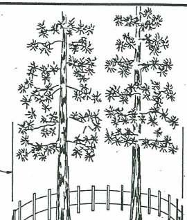
20 DRIP LINE CORRECT

21 BMP-8 Protection of Trees and Other Vegetation BMP-TSB TEMPORARY SEDIMENT BARRIERS Definition Temporary sediment barriers are temporary structures constructed to slow runoff and trap small amounts of sediment. Purpose To intercept and detain small amounts of sediment from small disturbed and unprotected areas. Applicability Any application where the structure is of a temporary nature, especially on construction sites. Planning Criteria Sediment barriers are useful at storm drain inlets, across minor swales and ditches, as dikes or berms, and along property lines in order to protect adjacent property. Sediment barriers can be built with straw bales, filter fabric, and sand bags. BMP9. STRAW BALE SEDIMENT BARRIER Definition Straw bale sediment barriers are temporary berms, diversions, or other barriers that are constructed of baled straw.
22 Purpose Straw bale sediment barriers are constructed to intercept and detain small amounts of sediment from unprotected areas of limited extent. Applicability Applicable to all construction sites, especially where runoff can discharge onto adjacent properties. These barriers are temporary in nature and should not be used where there is concentration of water in a channel or other drainage way. Advantages 1. If properly installed, the barriers can remove the bulk of coarse sediment from runoff before leaving the site. 2. Prevents sediment damage to adjacent property owners. 3. When the bale deteriorates, it can be broken up and spread as mulch. Disadvantages 1. The barriers have a short life expectancy of 3-6 months. 2. The barriers are not intended for use on cut and fill slopes. 3. The barriers are not intended for use on paved surfaces. 4. The barriers are ineffective if not properly installed because of undercutting and end flow. 5. Some counties discourage the use of straw bales because they are easily damaged and/or moved by construction equipment. 6. Source of weed or exotic seeds. Planning Criteria Since these barriers are designed to intercept surface runoff, they are only effective for small areas generally less than one-half / one acre and where slope lengths do not exceed 100 feet. The barriers may be used on single-family residential lots or moderate slopes of less than 20%. The length of slope above the barrier should be less than 200 feet. Installation A row of straw bales shall be placed along the contour of a gentle slope or at the toe of a steeper slope. They can be used in this way around the disturbance area or near the property boundary where runoff from the site passes onto an adjacent property. Maintenance
23 The barriers shall be checked periodically. Sediment which has accumulated needs to be removed after each storm. Bales must be replaced when rotten, disintegrating, or broken. Effectiveness The straw bale sediment barriers are only effective if they are properly installed and in accordance with the design criteria. Sandbags are more effective on paved surfaces than the straw bales, and filter fences are more effective on soil surfaces. The barriers are not effective for use to prevent or check channel erosion.
24 BMP10. FILTER FENCE Definition Filter fences are a temporary sediment barrier consisting of filter fabric attached to supporting Flow.. vertical face EMBEDDING DETAIL Angle first stoke toward previously laid bole Flow ANCHORING 2 re-bars. steel pickets 211 X 2" stakes to 21 ground DETAIL
25 posts. Usually a wire mesh or similar material is used to help support the fabric. Purpose Filter fences are constructed to intercept and detain sediment while decreasing the velocity of runoff. Applicability Applicable to all construction sites, especially where runoff can discharge onto adjacent properties or directly into streams. These barriers are temporary in nature and limited to siltations in which surface runoff is expected. They should not be used where there are concentrated volumes of water in channels or other drainage ways. Advantages 1. If properly installed, the filter fences can remove most of the sediment from surface runoff leaving the site. 2. Prevents sediment damage to adjacent property owners. 3. Prevents degradation of water quality, especially when used adjacent to water courses. 4. Reduces the velocity of runoff, runoff, and hence the erosive capacity. Disadvantages 1. The filter fences have a useful life expectancy of one year. 2. The fences are not intended for use in channels, drainage ways or on cut and fill slopes. 3. The fences are ineffective if not properly installed because of undercutting and end cutting. 4. The fences require some soil disturbance in order to entrench the filter fabric. 5. The fences require periodic maintenance and cleaning. Planning Criteria Since the fences are designed to intercept surface runoff, they are effective for areas of about 1-2 acres and where the maximum slope length behind the barriers is 100 feet. The fences may be used on slopes of less than 50 percent. Installation Filter fences are usually made by attaching filter fabric (Mirifi 100X, Exxon GTF 100S, or equivalent) to a wire mesh fence. Steel posts are spaced from 4 to 10 feet along the contour depending on the application and driven at least 1 foot into the ground. A trench (4 in. x 4 in.) is excavated along the line of posts and uphill from the barrier. The filter cloth is not only buried vertically, but also across the bottom of the trench into the direction of the water flow. The wire
26 mesh is fastened to the uphill side of the posts and extended into the trench. The filter cloth is then fastened to the uphill side of the posts and extended into the trench. The trench is backfilled over the toe of the filter cloth and the soil compacted against the filter cloth. Maintenance The filter fences should be checked immediately after each rain storm and shall be repaired as necessary to keep them functional. Sediment should be removed when deposits reach approximately one-half the height of the barrier and properly removed from the site. The material must never be placed below the filter fence. Any required repairs should be made immediately. Effectiveness The filter fences are only effective if they are properly installed and in accordance with the design criteria. In general, a filter fence can last about twice as long as a straw bale sediment barrier and is more effective in trapping sediments. The greater effectiveness of the filter fence is due to stronger construction, greater depth of ponding, and by allowing fewer soil particles to pass through it. BMPll. STRAW BALE-DROP INLET SEDIMENT BARRIER Definition Straw bale drop inlet barriers are temporary sediment barriers consisting of straw bales placed around drop inlets. Purpose Drop inlet sediment barriers are constructed to prevent sediment from entering the storm drain system in unpaved areas. Applicability Applicable to all construction sites where the drop inlet drains a relatively flat disturbed area with slopes less than 5 percent. The straw bale barriers can only be used prior to paving when bales can be staked into the ground for stability. They should not be placed around inlets receiving concentrated flows such as along major streets. Advantages 1. If properly installed, the drop inlet barriers can prevent sediment from entering the storm drain system. Disadvantages 1. Straw bales can be easily damaged by construction equipment operating in the area. Planning Criteria The drop inlet sediment barriers are for drainage areas of less than one acre. They are designed to keep sediment out of the storm drain system, and they do not have a sediment storage area.
27 Installation Straw bales are placed length wise around the inlet in a 4 in. deep trench. Orient the bales with the wires or bindings around the sides. All bales shall be abutted and staked. Backfill the excavated soil and compact it against the outside of the bales. Maintenance The barriers should be checked periodically and shall be repaired to keep them functional. Sediment which has accumulated may need to be removed after each storm and properly removed from the site. Bales must be replaced when rotten, disintegrating, or broken. Effectiveness The drop inlet protection devices are only effective if they are properly installed and in accordance with the design criteria. If the bales are not tightly abutted, sediment can freely enter the storm drain system. The straw bale devices are not effective and should not be used on paved streets at curb inlets. BMP12. SANDBAG CURB INLET SEDIMENT BARRIER Definition Sandbag curb inlet barriers are temporary sediment barriers consisting of sandbags placed on the uphill side of the inlet and overlapping onto the curb. Purpose Curb inlet sediment barriers are used to prevent sediment from entering the storm drain system in paved areas. Applicability Applicable to all construction sites where the roads are already paved with the curb inlets in place. The sandbag barriers are useful on streets which receive runoff flows of less than 0.5 cfs. Advantages 1. If properly installed, the sandbag barriers can prevent sediment from entering the storm drain system under low runoff flows. 2. Simple and cheap to install. Disadvantages 1. Once the area behind the sandbags fills with sediment, future runoff will enter the storm drain without the sediment settling out. 2. Sandbags and contents are treated as spoils and must be removed from the site or the contents used as backfill.
28 Planning Criteria The sandbag curb inlet sediment barriers are for drainage areas of less than 1 acre. They are designed to keep sediment out of the storm drain system when the roads are already paved. There is a small area of sediment storage behind the sandbags. Installation The sandbag should be of plastic woven material rather than burlap. Burlap bags rot and deteriorate, and as a result, can cause more problems if broken. Only clean washed sand shall be used to fill the bags. The sandbags should be placed in a curved row from the top of the curb at least 3 feet into the street. The row should be at least 6 feet from the inlet and curved at the ends which should be pointing uphill. Several layers of bags should be overlapped and packed tightly together in order to eliminate any spaces between the bags. Leave a 6 inch gap in the middle of the top row of sandbags to serve as the spillway. Maintenance The curb inlet barriers must be checked after each storm and shall be repaired to keep them functional. Sediment which has accumulated needs to be removed and placed where it will not enter the storm drain. Additional sediment storage capacity can be obtained by constructing a series of sandbag barriers along the curb and gutter so that each barrier traps a small amount of sediment. BMP13. FILTER BERM Definition A filter berm is a temporary ridge of gravel or crushed rock constructed across a graded driveway. Purpose To retain sediment on-site by retarding and filtering runoff while allowing water to be discharged from the site and construction traffic to proceed along the driveway. Applicability Filter berms are used primarily where graded driveways meet paved streets or across stabilized construction entrances. This application would only apply to parcels which are located upslope from the paved right-of-way. Filter berms may also be used as outlets for sediment barriers around construction sites and in uncompleted drainage ditches prior to roadway paving. Advantages 1. Prevents sediment from reaching public streets and storm drains. 2. Prevents sediment damage to adjacent property owners. 3. Prevents degradation of water quality, especially when used adjacent to water courses.
29 Disadvantages 1. Needs periodic repair and replacement because of vehicle damage. 2. When used around the perimeter of a construction site, the cleanup and removal of the berm is costly and can cause additional soil disturbance. 3. Practice is not suitable on steep slopes or in forested and vegetated areas. Planning Criteria Filter berms are used to filter runoff water for discharge from construction sites. The practice is best designed for use at construction entrances on up-sloping parcels. Although continuous filter berms may be used around construction sites, filter fences are more effective where vehicle traffic is restricted. Installation Deposit a ridge of well graded gravel or crushed rock (.75 to 3 inches) with a shovel or backhoe. Compact the material by rolling or tamping until it has the following dimensions. The dimensions of the berm depend on the location and application where installed across the construction entrance, the height should be 1.5 to 2 feet, the top width 3 to 5 feet and the side slopes 3:1 or flatter. When used where no vehicles will cross, the height can be up to 3 feet, the top width only 1 to 1.5 feet, and the side slopes 2:1. On sites where a filter berm is installed across a graded entrance which has not been stabilized with gravel mulch, filter fabric should be incorporated in the berm approximated 6 inches below the top surface. This makes cleanout and replacement much easier as only the top layer needs to be cleaned and/or replaced. Maintenance Remove all trapped sediment and clean out or replace clogged filter material after each storm. Repair and add material if vehicles compact the structures below minimum dimensions. The presence of ruts across the structure will lead to erosion problems. Effectiveness Filter berms are very effective in preventing sediment transport from construction sites. The practice is cost-effective when the berms are located on the permanent roadbeds. The gravel or crushed stone can be used as sub grade material before paving. BMP14. SILTATION BERM Definition A siltation berm is a temporary barrier of gravel or crushed rock covered with plastic sheeting constructed around construction sites. Purpose
30 To capture and retain runoff from construction sites, to allow sediments to settle out, and to direct runoff water through filter berms at outlets to stabilized drainage ways. Applicability The impermeable siltation berms are applicable to relatively flat construction sites and should be installed on the down slope sides of the disturbed areas. Advantages 1. Prevents sediment from reaching public streets and storm drains. 2. Prevents sediment damage to adjacent property owners. 3. Prevents degradation of water quality, especially when used adjacent to water courses. 4. Reduces the velocity of surface runoff, and hence the erosive capacity. Disadvantages 1. When used on the perimeter of construction sites, the cleanup and removal of the berm is costly and causes additional soil disturbance. 2. Practice is not suitable on steep slopes or in forested and vegetated areas. Planning Criteria Siltation berms are used to capture and retain runoff from construction sites. The berms should be sized to contain the runoff water from a design storm (20-year, 1-hour event). The sediments in the runoff water are allowed to settle out and the water is directed through filter berms located at points leading to stable drainage ways. Installation A ridge of gravel or crushed rock (.75 to 1.5 inches) should be mounded along the contour of the slope at the downhill side of the construction site. The height of the ridge should be sufficient to contain the specified volume of runoff. The height of the ridge should be at least 1.5 feet. The side slopes of the ridge should not exceed 2:1. Plastic sheeting (6 mil. thick) is placed over the berm. The sheeting width should be wide enough to cover the berm and allow at least 1 foot of additional sheeting on each side of the berm to allow anchoring. The sheeting is anchored by placing gravel or crushed rock on the edges to a depth of at least 3 inches and width of at least 8 inches. Maintenance Siltation berms must be inspected periodically, especially after each storm, and maintained to keep functional. The plastic sheeting must be replaced as necessary in order to retain runoff water and sediments on-site. Effectiveness
31 Siltation berms can be effective if they are properly installed and maintained on relatively flat sites. Filter fences are more effective in most situations, except where runoff needs to be directed to certain discharge points. BMP-TSS. TEMPORARY SOIL STABILIZATION PRACTICES (NON-VEGETATIVE) Definition Temporary soil stabilization practices are used to prevent soil erosion and/or enhance short-term vegetation during construction activities or until permanent BMPs, including long-term vegetation, have been installed. Purpose To temporarily stabilize bare and disturbed soils, to control soil erosion by protecting the soil surface from raindrop impact, to prevent soil compaction or crusting, to decrease runoff, to control weeds, to increase infiltration, to conserve moisture, and to provide mulch which enhances vegetation min. ELEVATION
32 Applicability Applicable to any construction site where soil has been disturbed and vegetation removed. These practices are applicable to provide temporary protection while the permanent vegetative cover is developing or to provide temporary protection during construction delays or until the permanent vegetation can be established. Advantages 1. These practices can prevent or reduce the discharge of degraded runoff water from construction sites. 2. Enhance temporary or permanent re-vegetation. Disadvantages 1. Increase construction costs. 2. Require periodic checking and maintenance after each storm. Planning Criteria Temporary soil stabilization practices are designed to protect disturbed and bare soils from potential erosion until re-vegetated or permanent BMPs are installed. These practices involve the use of various coverings and binders that either temporarily shield the soil surface from raindrop impact and runoff or temporarily bind the soil particles into a more resistant mass. Included in this non-vegetative category of practices are mulches, nettings, and chemical binders. Mulch materials include straw, wood chips, wood fiber, bark, and gravel. Heavy-weight netting materials such as jute matting and wood excelsior are effective in holding soil in place. Less dense nettings, such as plastic mesh, provide little if any soil protection, but can hold other mulch materials in place. The chemical soil binders are designed to bind the surface of the soil. Chemical binders can also be used as a mulch tackifer. The choice of mulch is determined by site characteristics, product availability, cost, and effectiveness. The most common mulch used in the Tahoe Basin is straw. In general, straw mulch offers the best results for both soil stabilization and protection and, in addition, enhances vegetative growth. Maintenance If applied correctly, these practices require little maintenance for one season or winter. However, if they are needed for more than one season, reapplication may be required. Effectiveness These practices can be very effective for short periods of time. Straw mulch appears to be the most cost effective in the Basin. BMP1S. STRAW MULCH Definition
33 Straw mulch is used as a temporary mulch to protect bare or disturbed soil areas that have not been seeded. Straw mulch can also be considered as a temporary practice when used as mulch for short-term vegetation, such as, grass seeding on a graded right-of-way. However, straw mulch is a permanent practice when used to help establish long-term or permanent vegetation. Purpose To temporarily stabilize bare and disturbed soils, to protect the soil surface from raindrop impact, to increase infiltration, to conserve moisture, to prevent soil compaction or crusting, to decrease runoff, and to provide a mulch for short-term vegetation if seeded. Applicability Applicable to any site where soil has been disturbed and vegetation removed. These practices provide temporary protection until the permanent vegetation can be established. As a temporary practice, they are applicable only for relatively short periods of time or until the next seeding season has been reached. Advantages 1. Prevents erosion from raindrop impact, runoff, and wind action. 2. Prevent the discharge of degraded runoff water from construction sites. 3. Enhance re-vegetation efforts, either temporary (short-term) or permanent (long-term). 4. Not toxic to vegetative growth. Disadvantages 1. Increase construction costs. 2. Requires matting, crimping, punching, or other methods to hold it in place, especially on steep slopes. 3. Provides only short-term protection (one season or winter). 4. Weed growth is common. 5. Cleanup cost may be high if the mulch is applied during winds. 6. Straw mulch cannot be blown as far as hydro mulch. Planning Criteria Straw is an excellent mulch material and widely used in the Tahoe Basin. Because of its length and bulk, it is highly effective in reducing the impact of raindrops and in moderating the microclimate of the soil surface. Straw mulch can be applied by hand on small sites and blown on by machine on large sites. Straw blowers have a range of about 50 feet. Some commercial models advertise a range up to 85 feet and a capacity of 15 tons per hour. Straw mulch should cover the exposed area to a uniform depth. If the mulch is being used without seeding, then the depth can
34 range from 2 to 4 inches. However, the mulch should not be applied more than 2 inches deep on seeded sites. If the straw is applied at rates higher than 3 tons per acre, the mulch may be too dense for seedlings to penetrate. Approximately one bale of straw covers 1000 square feet adequately. The soil surface should be barely visible through the straw mulch. Straw must be anchored to keep it from blowing away. Straw mulch is commonly anchored by: 1. Crimping, rolling, disking, or punching into the soil; 2. Covering with a netting; or 3. Spraying with a chemical or tackifer. On small sites, where straw has been distributed by hand, it can be anchored by hand punching it into the soil every 1 to 2 feet with a dull, round-hosed shovel. A sharp shovel will merely cut the straw and not anchor it. Installation 1. Obtain clean wheat, barley, oat, or rice straw in order to prevent the spread of noxious weeds in the Basin. Avoid moldy, compacted straw because it tends to clump and is not distributed evenly. 2. The straw shall be evenly distributed by hand or machine to the desired depth. 3. Anchor the mulch using an acceptable method. On areas adjacent to streams, drainage ways, or Lake Tahoe netting is highly recommended in order to prevent any mulch material from entering the water. Straw can increase the BOD levels and upon decomposition, release some nutrients. 4. Straw must be anchored on slopes steeper than 2:1. Maintenance If properly applied and anchored, little additional maintenance is required during the first few months. After high winds, mulched areas should be checked for adequate cover and re-mulched if necessary. Effectiveness Straw mulch is very effective if it is kept in place. Anchoring increases the costs, but it is necessary on steep slopes. Although jute matting over straw is very costly, it is one of the most effective treatments for critical areas. BMP16. HYDROMULCH Definition Hydro mulch is the combination of wood fiber and water and is applied hydraulically as slurry. Purpose To temporarily stabilize bare and disturbed soils, to protect the soil surface from raindrop impact, and to provide mulch for short-term vegetation if the areas were seeded.
35 Applicability Applicable to any site where the soil has been disturbed and vegetation removed, however, the practice is only recommended for use on steep, inaccessible slopes, such as highway cut and fill slopes. Advantages 1. Prevents erosion from raindrop impact, surface runoff, and wind action. 2. Can be applied on a windy day. 3. Can provide temporary protection on slopes greater than 50 percent. 4. Can be used as a carrier for straw mulch. Disadvantages 1. Must be applied at a heavy rate in order to be effective as a mulch. 2. Provides only short-term protection. 3. Not cost-effective for small areas or small jobs. 4. Will not adhere well to steep slopes on decomposed granite soils. 5. Provides little protection over winter. Planning Criteria Hydromulch consists basically of wood fiber and water. Wood fiber is a natural, short fiber product produced from clean wood chips. A nontoxic dye is used to color the mulch green in an effort to aid visual metering during its application. When sprayed on the surface of the soil, the fibers form an absorbent cover, allowing percolation of water. Although it can provide a complete ground cover, the short fibers do not provide enough mass to dissipate all of the energy from falling raindrops and flowing water. Installation 1. Wood fiber and water are agitated into a well mixed slurry. Wood fiber can be applied at rates of pounds per acre. At rates of 2000 pounds per acre or less, the mulch is not very effective. When used as a tackifer for straw mulch, it should be applied at a rate of 750 pounds per acre. 2. Fertilizer 63) and/or tackifers can be introduced to the slurry before the wood fiber is added. 3. NEVER ADD SEED TO HYDROMULCH.
36 4. The slurry is hydraulically sprayed onto the areas within 125 feet of a road. When a 100 foot hose is available, the range can be extended up to 200 feet. 5. Do not use on decomposed granite slopes over 30%. Maintenance Hydromulched areas shall be inspected periodically for damage and re-mulched if necessary. Fencing or traffic barriers may be necessary to protect treated areas. Effectiveness Hydromulch is not effective as mulch. It is preferable to straw mulch only for limited applications. It can be used very effectively as a tackifer for straw mulch. BMFI7. PINE NEEDLE MULCH Definition Pine needle mulch is used as a temporary or permanent mulch to protect bare or disturbed areas. Purpose To temporarily stabilize bare and disturbed soils, to protect the soil surface from raindrop impact, to increase infiltration, to conserve moisture, to prevent soil compaction or crusting, to decrease runoff, and to provide a mulch for long-term vegetation if planted. Applicability Applicable to any construction site where soil has been disturbed and vegetation removed. Especially applicable to areas of site development where pine needles can be raked and stock piled prior to disturbance and then applied as a temporary mulch where needed. Advantages 1. Low cost when present on site. 2. Very effective as a mulch, either temporary or permanent when used around trees and shrubs. 3. More aesthetic than other mulches. Disadvantages 1. Labor intensive and thus applicable only for small areas. 2. Not effective on steep bare slopes of decomposed granite soil. Planning Criteria
37 When pine needles are available on a site before development starts, this natural mulch can be raked and stockpiled for future use. The pine needles should only be gathered from areas within the limits of clearing and grading. Once the boundary fencing is installed, areas where the natural pine needle mulch will be destroyed can be identified and this valuable mulch gathered up. Installation 1. Rake and stockpile pine needles prior to any site disturbance. 2. Spread pine needles by hand to a uniform thickness of 2-to 3-inches on areas where temporary mulch is required. Do not use on areas subject to vehicle traffic. 3. Excess pine needles can be returned to the forest floor or used as a mulch between permanent landscape plantings. 4. Do not use on decomposed granite slopes over Maintenance Mulched areas should be inspected periodically for damage and re-mulched if necessary. Effectiveness Pine needles are very effective under natural conditions, and thus, should be just as effective when used as mulch. Pine needles are less likely to be subjected to wind damage. BMP18. JUTE NETTING Definition Jute netting is a heavy woven jute mesh with l-inch by l-inch spacing. Although frequently referred to as jute matting, the size of the spacing makes netting the more appropriate term. Purpose To hold mulch in place on steep slopes and along drainage ways and to help establish revegetation in critical areas. As a temporary mulching practice over straw, it stabilizes bare and disturbed soils, protects the soil surface from raindrop impact, increases infiltration, conserves moisture, prevents soil crusting or compaction, and reduces erosion caused by overland flow. Applicability Applicable to steep slopes where soil has been disturbed and vegetation removed. Although distributors claim that jute netting can be used alone to hold soil in place, experience in the Tahoe Basin indicates that jute netting provides little soil stabilization by itself. Based on the cost of jute netting, it should be utilized primarily with straw mulch on steep slopes with short slope lengths. It should also be part of the permanent, long-term re-vegetation practices. Advantages
38 1. Netting applied over straw mulch is one of the more effective soil stabilization practices on steep slopes in the Tahoe Basin. 2. It is an effective way to help establish permanent vegetation on these steep slopes. 3. The earth tones of jute are more aesthetically pleasing than the plastic netting. Disadvantages 1. High cost of material and installation. 2. Higher cost than plastic netting which provides similar results. 3. Deteriorating jute is not aesthetically pleasing. Planning Criteria Jute netting is a heavy fiber mesh generally available in rolls 4 feet wide, 225 feet long, and weighs about 90 pounds. The material is rolled out up and down the slope, never along the contour. If the jute netting is placed along the contour, creeping snow loads will peel it off the slope. The material is overlapped and stapled to slopes to provide a uniform covering. Results in the Tahoe Basin indicate that jute netting is effective when applied over another mulch, preferably straw mulch. Because of the high cost of jute netting, it is usually not cost effective to use it as a temporary soil stabilization practice. It is most effective when applied in combination with seeding and straw mulch as part of the permanent re-vegetation on steep slopes. Installation 1. Seed and/or mulch the disturbed area. 2. Starting above the mulched and/or seeded area, bury the top end of the netting in a trench at least 4 inches deep and 8 inches wide. The trench shall be backfilled and tamped. 3. The netting shall extend beyond the edge of the mulched and/or seeded area at least 1 foot on the sides and 3 feet on the top and bottom. Fasten with a row of staples 1 foot apart. 4. Do NOT rollout along the contour. 5. Rollout the netting up and down the slope and secure with staples. Wire staples of No. 11 gauge or heavier should be used. The "U" shaped staples shall be 6 to 10 inches long with an l-inch crown. Use longer staples on loose or sandy soils. 6. Overlap the netting at least 4 inches on the sides and secure with staples 5 feet apart along the overlap. 7. Overlap lower end of uphill strip over downhill strip at least 1 foot and secure with staples 1 foot apart. 8. Continue adding strips of netting until entire mulched area is covered and secured with staples.
39 9. The netting shall be cut around big rocks or tucked in around smaller ones to prevent bridging. Maintenance If the netting is properly installed, little maintenance is required. The areas shall be inspected periodically, especially late fall and early spring, for any damage. Repair and re-staple netting if necessary. Effectiveness Jute netting is very effective in providing soil protection when applied over a mulch and in aiding the establishment of permanent vegetation. The use of jute netting is cost effective on steep slopes and highways cut and fill slopes. BMP19. PLASTIC NETTING Definition Plastic netting is used to hold mulch in place on steep slopes. Purpose To hold mulch in place on steep slopes and along drainage ways and to help establish revegetation in critical areas. As a temporary mulching practice over straw, it stabilizes bare and disturbed soils, protects the soil surface from raindrop impact, increases infiltration, conserves moisture, prevents soil crusting or compaction, and reduces erosion caused by overland flow. Applicability Applicable to any sites where soil has been disturbed and vegetation removed. Plastic netting provides little soil stabilization by itself and should never be used alone. Plastic netting is used primarily to hold mulches in place on steep slopes. Applicable to long-term or short-term revegetation practices. Advantages 1. Netting applied over straw mulch is one of the more effective soil stabilization practices on steep slopes in the Tahoe Basin. 2. When used in combination with seeding and mulches, it is an effective way to help establish permanent vegetation on these steep slopes. 3. The cost of plastic netting is considerably less than jute netting. Disadvantages 1. High cost of installation. 2. Cost of material.
40 3. Not as aesthetically pleasing as jute netting. Planning Criteria Plastic netting is available in rolls which range in width from 4 to 15 feet and up to 2500 feet in length. The material is rolled out up and down the slope, never along the contour. If placed along the contour, creeping snow loads will peel it off the slope. The netting is overlapped and stapled to the slopes to provide a uniform covering over the mulched and/or seeded area. Results in the Tahoe Basin indicate that plastic netting is most effective when applied over straw mulch and seed. Plastic netting is available in various colors which differ in their rate of deterioration due to ultra-violet radiation. The green netting which may be aesthetically pleasing is designed to last about 2 years. However, due to the high elevations of the Tahoe Basin, the green netting tends to start deteriorating after one season, and thus, is inadequate. Black plastic netting is longer lasting and recommended for use in the Tahoe Basin. Installation 1. Seed and mulch the disturbed area. 2. Starting above the mulched and/or seeded area, bury the top end of the netting in a trench at least 4 inches deep and 8 inches wide. The trench shall be backfilled and tamped. 3. The netting shall extend beyond the edge of the mulched and/or seeded area at least 1 foot on the sides and 3 feet on the top and bottom. Fasten with a row of staples 1 foot apart. 4. Rollout the netting up and down the slope and secure with staples. Wire staples of No. 11 gauge or heavier should be used. The "U" shaped staples shall be 6 to 10 inches long with a l-inch crown. Use longer staples on loose or sandy soils. 5. Overlap the netting at least 4 inches on the sides and secure with staples 5 feet apart along the overlap. 6. Overlap lower end of uphill strip over downhill strip at least 1 foot and secure with staples 1 foot apart. 7. Continue adding strips of netting until entire mulched area is covered and secured with staples. 8. The netting shall be cut around big rocks or tucked in around smaller ones to prevent bridging. Maintenance If the netting is properly installed, little maintenance is required. The areas shall be inspected periodically, especially late fall and early spring, for any damage. Repair and re-staple netting if necessary. Effectiveness
41 Plastic netting is as effective as jute netting and because of its lower cost, it is more cost effective. BMP20. WOOD EXCELSIOR BLANKET Definition A mat made of interlocking wood excelsior fibers with a paper or plastic mulch net backing on one side only (similar to the material used for evaporative cooler pads). Purpose To provide a protective mulch on steep slopes and along drainage ways and to help establish vegetation in critical areas. As a temporary mulching practice, it stabilizes bare and disturbed soils, protects the soil surface from raindrop impact, increases infiltration, conserves moisture, prevents soil crusting or compaction, and reduces erosion caused by overland flow. Applicability Applicable to any areas where soil has been disturbed and vegetation removed. It is a major alternative to jute netting and straw mulch. It can be utilized when it is cheaper than jute and straw or if installation is easier. It is an effective method on steep slopes and when combined with permanent re-vegetation practices. Advantages 1. Combines two steps, mulch and netting, into one. 2. Cost competitive with jute and straw. 3. Easier installation on some sites, and thus, lower installation costs. Disadvantages 1. Cost of material and installation. Planning Criteria Wood excelsior blankets are available in 3-by 150-foot rolls and 4-by 180-foot rolls. The material is rolled out up and down the slope just like other netting material. It is never applied along the contour. The material is butt-joined and securely stapled to provide a uniform covering. The excelsior blankets are much better suited for use as a temporary practice than other mulches and nettings because they can be rolled up, removed, and reused if not damaged. Also, the blankets can be contained with permanent, long-term vegetation practices. Installation 1. Prepare and/or seed the disturbed area. 2. Starting above the disturbed area, bury the top end of the blanket in a trench at least 4 inches deep and 8 inches wide. The trench shall be backfilled and tamped.
42 3. The blanket material shall extend beyond the edge of the disturbed and/or seeded area at least 1 foot on the sides and 3 feet on the top and bottom. Fasten with staples 1 foot apart. Wire staples of No. 11 gauge or heavier should be used. The "U" shaped staples shall be 6-to 10-inches long with a 1-inch crown. Use longer staples on loose or sandy soils. 4. Rollout the blanket up and down the slope and secure with staples. Staples shall be applied at 2 foot intervals along the sides of the blanket and at 4 foot intervals along the center of the blanket. 5. Butt-join the blankets on the sides and ends and secure with staples. 6. The blanket shall be cut around big rocks or tucked in around smaller ones to prevent bridging and flows underneath the blankets. Maintenance If the blankets are properly installed, little maintenance is required. The areas shall be inspected periodically, especially late fall and early spring, for any damage. Repair, replace, and re-staple blankets if necessary. Effectiveness Wood excelsior blankets are very effective in providing soil protection and in aiding the establishment of vegetation. They can be as cost effective as jute and straw on steep slopes and more cost effective on graded construction sites because of easier installation. BMP2l. EROSION CONTROL BLANKETS OR GEOTEXTILES Definition Erosion control blankets or geo-textiles are a generic name given to support and filter fabrics that are placed in contact with the soil. Purpose To provide a protective mulch on steep slopes or along drainage ways and to help establish vegetation in critical areas. As a temporary mulching practice, it stabilizes bare and disturbed soils, protects the soil surface from raindrop impact, increases infiltration, conserves moisture, prevents soil crusting or compaction, and reduces erosion caused by overland flow. As a channel liner, it minimizes channel erosion by restraining the soils from movement while allowing free passage of water along the plane of the fabric. Applicability Applicable to any area where soil has been disturbed and vegetation removed. It is a major alternative to jute netting and straw mulch. It can be utilized when it is cheaper or if installation is easier. Advantages 1. Combines two steps, mulch and netting, into one.
43 2. Cost competitive with jute and straw. 3. Easier installation on some sites, and thus, lower installation costs. 4. Can be used effectively as a channel liner. Disadvantages 1. Cost of materials and installation. 2. Plastic or wire netting may not be as aesthetically pleasing as jute netting. Planning Criteria Blankets are available in various widths, usually 6 to 8 feet, depending on the manufacturer. The material comes in rolls, 50 to 100 feet in length. The blanket material is easily rolled out on graded surfaces and securely stapled to provide a uniform covering. The blankets can be used with permanent, long-term vegetation practices. Installation 1. Prepare and/or seed the disturbed area. 2. Starting above the disturbed area, bury the top end of the blanket in a trench at least 4 inches deep and 8 inches wide. The trench shall be backfilled and tamped. 3. The blanket material shall extend beyond the edge of the disturbed and/or seeded area at least 1 foot on the sides and 3 feet on the top and bottom. Fasten with staples 1 foot apart. Wire staples of No. 11 gauge or heavier should be used. The "U" shaped staples shall be 6-to 10-inches long with a l-inch crown. Use longer staples on loose or sandy soils. 4. Rollout the blanket up and down the slope and secure with staples. Staples shall be applied at 2 foot intervals along the sides of the blanket and at 4 foot intervals along the center of the blanket. 5. Butt-join the blankets on the sides and ends and secure with staples. 6. The blanket shall be cut around big rocks or tucked in around smaller ones to prevent bridging and flows underneath the blankets. Maintenance If the blankets are properly installed, little maintenance is required. The areas shall be inspected periodically, especially late fall and early spring, for any damage. Repair, replace, and re-staple blankets if necessary. Effectiveness Erosion control blankets are very effective in providing soil protection and in aiding the establishment of vegetation. They can be as cost effective as jute and straw on steep slopes and more cost effective on graded construction sites because of easier installation.
44 BMP22. CHEMICAL MULCHES AND TACKIFIERS Definition A tackifer is a gluey substance used to help hold down mulches, particularly straw and wood fiber. Chemical mulches are organic or plastic substances sprayed on soils to form a crust. Purpose To provide temporary soil stabilization and dust controlled by "tacking" fibers to slopes or forming a crust on the soil surface. Applicability Applicable to any constructing site where soil has been disturbed and vegetation removed. The chemical "binders" can provide temporary protection and dust control on inactive construction sites. This practice is not utilized in the Tahoe Basin because the alternative practices are more acceptable and readily available. In addition, some of the asphaltic tackifiers and chemicals may degrade water quality. Planning Criteria The use of chemical mulches and tackifiers is not recommended in the Tahoe Basin. Although the chemical mulches can provide temporary soil stabilization by binding the surface soil particles together, they reduce the porosity of soil. The reduced soil porosity and can inhibit the growth of vegetation, especially in areas of low rainfall. Hydromulch (BMP-16) is recommended as a preferable alternative. It can be used effectively as mulch or as a tackifier over straw. BMP-TD TEMPORARY RUNOFF CONTROL (DIVERSIONS) ON SLOPES Definition Temporary diversion practices divert surface runoff away from disturbed and bare areas and direct it to a stable outlet. Purpose To divert the flow of surface runoff away from bare and disturbed slopes. Applicability Applicable to any construction site where it is necessary to intercept runoff from upslope areas and divert it away from newly constructed un-stabilized, unprotected, or recently seeded slopes. These practices are also applicable on long uninterrupted slope lengths to divert runoff and direct it along the contours. Advantages 1. If properly installed and maintained, the temporary diversion practices can prevent the discharge of degraded runoff water from construction sites.
45 Disadvantages 1. Temporary diversion BMPs increase construction costs. 2. These practices require periodic checking and maintenance, especially after each storm. Planning Criteria Diversion practices concentrate the volume of surface runoff, convert it to channel flow, and as a result, increase its velocity and erosive force. It is necessary to plan in advance for the release of runoff collected in diversions. Runoff must be discharged onto a stabilized area to reduce its velocity. In some cases this can be accomplished by reducing the gradient of the diversion. Where the runoff cannot be released by conveying it laterally, it can be drained over the face of the slope itself by using grade stabilization structures, such as a slope drain, either on the surface of the slope or below the surface. At the slope drain outlet, energy dissipaters are required to reduce potential erosion problems by reducing the velocity of the runoff water. Diversions may also be used at intervals on long uninterrupted slopes to reduce slope length. Diversions may be used to collect runoff from a construction site and divert it to a sediment trap or basin. Maintenance Temporary diversion practices require much more maintenance than permanent BMPs. These practices require checking after each storm and repairs must be completed immediately. Effectiveness The diversion practices are only effective if they are properly installed and in accordance with the design criteria. These practices are designed to be effective only during the grading season or until permanent BMPs are installed or the disturbed areas stabilized. BMP23. DIVERSION DIKE Definition Temporary ridges of compacted soil constructed immediately above new cut or fill slopes and installed with sufficient grade to divert runoff away from bare, exposed slopes. Purpose To intercept overland flow from upslope areas and divert it away from newly constructed, unstabilized, unprotected, or recently seeded slopes to a stable outlet. Applicability Applicable to all construction sites where disturbed and bare slopes can receive runoff from upslope areas. Advantages 1. Prevent slope failures.
46 2. Prevents damage to adjacent property owners. 3. Prevents the degradation of water quality. 4. Increase potential infiltration. 5. Increase the time of concentration, and thus reduce the peaking of runoff. Disadvantages 1. Concentrate the volume of runoff water. 2. Convert overland flow to channel flow. 3. May accumulate sediment and require cleanout. Planning Criteria Slopes that are formed during cut and fill operations should be protected from storm water runoff by installing a dike, swale, or combination of both at the top of the slope to divert runoff away. A combination dike and swale is easily constructed by a single pass of a bulldozer or grader and compacted by a second pass of the tracks or wheels over the ridge. The drainage area above the diversion should be less than 5 acres. The diversion structures should be installed during the grading season and remain in place until permanent BMPs are installed and/or the slopes are stabilized. Installation 1. Construct a ridge of compacted soil immediately above cut and fill slope. Dikes should not be established on slopes greater than 15 percent. 2. Top width shall be at least 2 feet. 3. Height of the dike shall be at least 18 inches from the existing ground. 4. Side slopes shall be 2:1 or flatter. 5. Dike shall have sufficient grade (1 to 3 percent) in order to provide drainage to a stable outlet. 6. Diverted runoff from an undisturbed area can discharge directly to a stabilized area or into a grade stabilization structure. 7. Diverted runoff from a construction site must be conveyed to a sediment trap or sediment basin before being discharged. 8. All dikes shall be machine-compacted with the tires or tracks going over at least 90 percent of the surface.
47 9. In some forested areas, where top of slope access is limited, diversion dikes can be constructed as a dozer finishes the slope by carrying fill upslope and dumping it at the crest. Machine compaction of the ridge is not possible in this instance. 10. Diverted runoff shall not overtop the dike. Maintenance Inspect periodically and maintain as required. Locate any damaged areas after each storm and repair immediately. Any accumulated sediment should be cleaned out when deposits reach approximately one-half the height of the dike. Effectiveness The dikes are only effective if they are properly installed and in accordance with the design criteria. The dikes should not be used to divert channel flows.
48 BMP24. DIVERSION SWALE Definition 2: I slopes or f10tter Cut or fi II slope SECTION not to scale SECTION Dike constructed dozer moving soil upslope and dumping at top of slope. Diversion dike to be constructed ot top of
49 Temporary ditches cut into the soil constructed immediately above new cut or fill slopes and installed with sufficient grade to divert runoff away from the erodible slopes. Purpose To intercept overland flow from upslope areas and divert it away from newly constructed, unstabilized, unprotected, or recently seeded slopes to a stable outlet. Applicability Applicable to all construction sites where disturbed and bare slopes can receive runoff from upslope areas. Advantages 1. Prevent slope failures. 2. Prevents damage to adjacent property owners. 3. Prevents the degradation of water quality. 4. Increase potential infiltration. 5. Increase the time of concentration, and thus reduce the peaking of runoff. Disadvantages 1. Concentrate the volume of runoff water. 2. Convert overland flow to channel flow. 3. May accumulate sediment and require cleanout. Planning Criteria Slopes that are formed during cut and fill operations should be protected from storm water runoff by installing a dike, swale, or combination of both at the top of the slope to divert runoff away. A combination dike and swale is easily constructed by a single pass of a bulldozer or grader and compacted by a second pass of the tracks or wheels over the ridge. The drainage area above the diversion should be less than 5 acres. The diversion structures should be installed during the grading season and remain in place until permanent BMPs are installed and/or the slopes are stabilized. Installation 1. Construct a ditch immediately above the cut and fill slope. Swales should not be established on slopes greater than 15 percent. 2. Bottom width shall be at least 2 feet.
50 3. Depth o f the swale shall be at least 18 inches from the existing ground. 4. Side slopes shall be 2:1 or flatter. 5. Swale shall have sufficient grade (1-3 percent) in order to provide drainage to a stable outlet. 6. Diverted runoff from an undisturbed area can discharge directly to a stabilized area or into a grade stabilization structure. 7. Diverted runoff from a construction site must be conveyed to a sediment trap or sediment basin before being discharged. 8. Diverted runoff shall not overtop the swale. Maintenance Inspect periodically and maintain as required. Locate any areas where the runoff overtopped the swale and repair immediately. Any accumulated sediment should be cleaned out when deposits fill up approximately one half the depth of the swale. Effectiveness The diversion swales are only effective if they are properly installed and in accordance with the design criteria. If drainage areas above the diversion structures are larger than 5 acres, design must include runoff calculations and follow the specifications for permanent waterways. A larger cross section and a channel lining will be required to handle the larger flows. Swales are more effective than dikes because they tend to be more stable. The combination of swale with a dike on the downhill side is the most effective and cost effective where equipment access is not limited. BMP25. PERIMETER DIKE Definition A temporary ridge of compacted soil constructed along the perimeter of the construction site or disturbed areas. Purpose To prevent off-site runoff from entering the disturbed area and to convey sediment laden runoff from on-site to a sediment trap or basin. Applicability Applicable to all construction sites where erodible soils can be exposed to runoff from upslope areas. Advantages 1. Prevents damage to adjacent property owners.
51 2. Prevents the discharge of degraded runoff water from construction sites. Disadvantages 1. Increase construction costs. 2. Requires periodic maintenance and cleanout. 3. Concentrate the volume and velocity of runoff water. Planning Criteria Diversion practices concentrate the volume of surface runoff, convert it to channel flow, and as a result, increase its velocity and erosive force. It is necessary to plan in advance for the release of runoff collected by perimeter dikes and swales. The diverted runoff from the undisturbed upland area can be discharged directly onto a stabilized area or into a grade stabilization structure. However, the diverted runoff from the construction site or disturbed area must be conveyed to a sediment trap or basin or to an area protected by sediment. Installation 1. Construct a ridge of compacted soil around the disturbed area. Dikes should not be constructed on slopes greater than 15 percent. 2. Top width shall be at least 2 feet. 3. Height of the dike shall be at least 18 inches from the existing ground. 4. Side slopes shall be 2:1 or flatter. 5. Dike shall have sufficient grade (1 to 3 percent) in order to provide drainage to a stable outlet. 6. Diverted runoff from an undisturbed area can discharge directly to a stabilized area or into a grade stabilization structure. 7. Diverted runoff from a construction site must be conveyed to a sediment trap or sediment basin before being discharged. 8. All dikes should be machine-compacted. 9. Diverted runoff shall not overtop the dike. Maintenance Inspect periodically and maintain as required. Locate any damaged areas after each storm and repair immediately. Any accumulated sediment should be cleaned out when deposits reach approximately one-half the height of the dike. Effectiveness
52 The dikes are only effective if they are properly installed and in accordance with the design criteria. The dikes should not be used to divert channel flows. BMP26. PERIMETER SWALE Definition A temporary excavated ditch constructed along the perimeter of the construction site or disturbed area. Purpose To prevent off-site runoff from entering the disturbed area and to convey sediment laden runoff from on-site to a sediment trap or basin. Applicability Applicable to all construction sites where erodible soils can be exposed to runoff from upslope areas. Advantages 1. Prevents damage to adjacent property owners. 2. Prevents the discharge of degraded runoff water from construction sites. Disadvantages 1. Increase construction costs. 2. Require periodic maintenance and cleanout. 3. Concentrate the volume and velocity of runoff water. Planning Criteria Diversion practices concentrate the volume of surface runoff, convert it to channel flow, and as a result, increase its velocity and erosive force. It is necessary to plan in advance for the release of runoff collected by perimeter dikes and swales. The diverted runoff from the undisturbed upland area can be discharged directly onto a stabilized area or into a grade stabilization structure. However, the diverted runoff from the construction site or disturbed area must be conveyed to a sediment trap or basin or to an area protected by sediment. Installation 1. Excavate a ditch around the disturbed area. Swales should not be constructed on slopes greater than 15 percent. 2. Bottom width shall be at least 7 feet and should be level. 3. Depth shall be at least 1 foot.
53 4. Side slopes shall be 2:1 or flatter. The slopes need to be flat enough t o allow construction traffic to cross if desired. 5. Swales shall have sufficient grade (1-to 3percent) in order to provide drainage to a stable outlet. 6. Diverted runoff from an undisturbed area can discharge directly to a stabilized area or into a grade stabilization structure. 7. Diverted runoff from a construction site must be conveyed to a sediment trap or sediment basin before being discharged. 8. Diverted runoff shall not overtop the swale. Maintenance Inspect periodically and maintain as required. Locate any areas where the runoff overtopped the swale and repair immediately. Any accumulated sediment should be cleaned out when deposits fill up approximately one half the depth of the swale. Effectiveness The diversion swales are only effective if they are properly installed and in accordance with the design criteria. If drainage areas above the diversion structures are larger than 5 acres, design must include runoff calculations and follow the specifications for permanent waterways. A larger cross section and a channel lining will be required to handle the larger flows. Swales are more effective than dikes because they tend to be more stable. The combination of swale with a dike on the downhill side is the most effective and cost effective where equipment access is not limited. BMP27. INTERCEPTOR DIKE Definition A temporary ridge of compacted soil constructed across disturbed areas or graded rights-of-way. Purpose To shorten the length of exposed slopes and reduce the erosion potential by intercepting runoff and diverting it to a sediment trap or basin. Applicability Applicable to any construction site where it is necessary to intercept on-site runoff and divert it away from un-stabilized areas. Advantages 1. Prevents damage to adjacent property owners. 2. Prevents the discharge of degraded runoff water from construction sites.
54 Disadvantages 1. Increase construction costs. 2. Require periodic maintenance and cleanout. 3. Concentrate the volume and velocity of runoff water. Planning Criteria Diversion practices concentrate the volume of surface runoff, convert it to channel flow, and as a result, increase its velocity and erosive force. It is necessary to plan in advance for the release of runoff collected by interceptor dikes and swales. The diverted runoff from the construction site or graded right-of-way must be conveyed to a sediment trap or basin or to an area protected by a sediment barrier. The drainage area should be less than 5 acres. The diversion structures should be installed during the grading season and remain in place until permanent BMPs are installed or the disturbed areas stabilized. Installation 1. Construct a ridge of compacted soil across the disturbed areas or graded right-of-way. On graded rights-of-way gravel or crushed 2. Top width shall be at least 2 feet. 3. Height of the dike shall be at least 18 inches from the existing ground. 4. Side slopes shall be 2:1 or flatter. 5. Dike shall have sufficient grade (1 to 3 percent) in order to provide drainage to a stable outlet. 6. Diverted runoff from a construction site must be conveyed to a sediment trap or sediment basin before being discharged. 7. All dikes shall be machine-compacted. 8. Diverted runoff shall not overtop the dike. Maintenance Inspect periodically and maintain as required. Locate any damaged areas after each storm and repair immediately. Any accumulated sediment should be cleaned out when deposits reach approximately one-half the height of the dike. Effectiveness The dikes are only effective if they are properly installed and in accordance with the design criteria. The dikes should not be used to divert channel flows.
55 BMP28. INTERCEPTOR SWALE Definition A temporary excavated ditch constructed across disturbed areas or graded rights-of-way. Purpose To shorten the length of exposed slopes and reduce the erosion potential by intercepting runoff and diverting it to a sediment trap or basin. Applicability Applicable to any construction site where it is necessary to intercept on-site runoff and divert it away from un-stabilized areas. Advantages 1. Prevents damage to adjacent property owners. 2. Prevents the discharge of degraded runoff water from construction sites. Disadvantages 1. Increase construction costs. 2. Require periodic maintenance and cleanout. 3. Depending on slopes, can concentrate the volume and velocity of runoff water. Planning Criteria Diversion practices concentrate the volume of surface runoff, convert it to channel flow, and as a result, increase its velocity and erosive force. It is necessary to plan in advance for the release of runoff collected by interceptor dikes and swales. The diverted runoff from the construction site or graded right-of-way must be conveyed to a sediment trap or basin or to an area protected by a sediment barrier. The drainage area should be less than 5 acres. The diversion structures should be installed during the grading season and remain in place until permanent BMPs re installed or the disturbed areas stabilized. Installation 1. Excavate a ditch across the disturbed area or graded right-of-way. 2. Bottom width shall be at least 5 feet and should be level. 3. Depth shall be at least 1 foot. 4. Side slopes shall be 2:1 or flatter.
56 5. Swales shall have sufficient grade (1 to 3 percent) in order to provide drainage to a stable outlet. 6. Diverted runoff from a construction site must be conveyed to a sediment trap or sediment basin before being discharged. 7. On long uninterrupted disturbed areas or right-of-way, the interceptor swales shall be spaced as follows: Slope Distance between Swales 10% 100 feet 5-10% 200 feet 5% 300 feet 8. Swales shall not be constructed on slopes greater than 15 percent. Maintenance Inspect periodically and maintain as required. Locate any areas where the runoff overtopped the swale and repair immediately. Any accumulated sediment should be cleaned out when deposits fill up approximately one half the depth of the swale. Effectiveness Interceptor swales are only effective if they are properly installed in accordance with the design criteria. Swales are more effective than dikes because they tend to be more stable especially on construction sites and graded rights-of-way. BMP-TGSS. TEMPORARY GRADE STABILIZATION STRUCTURES Definition Temporary structures constructed of non-erodible material that can carry diverted runoff down steep slopes to stable points of discharge below. The structures may be a down drain, flexible down drain, pipe drop, or chute (flume). Purpose To temporarily convey runoff down the face of a cut or fill slope until permanent BMPs are installed and the slope is stabilized with vegetation. Applicability Applicable to any construction site where it is necessary to intercept runoff from upslope areas and convey it down cut or fill slopes. The structures should be installed immediately after completion of the cut or fill and before re-vegetation of the slopes. BMP29. FLEXIBLE DOWNDRAIN Definition
57 A flexible down drain is a flexible conduit of heavy duty fabric or other flexible material which is to be used as a temporary down drain. Purpose To convey runoff down the face of cut or fill slopes or other steep areas to stable discharge points during construction. Applicable Applicable to any construction site where runoff water can accumulate above cut or fill slopes and must be conveyed over the slope without causing erosion. Advantages 1. To protect un-stabilized areas from erosion by concentrated flows. 2. To prevent the discharge of degraded runoff water from construction sites. Disadvantages 1. Increase construction costs. 2. These practices require periodic checking and maintenance, especially after each storm. Planning Criteria These structures are used to convey runoff from the top to the bottom of a slope. They are usually used in combination with top-of-slope diversion dikes and/or swales. It is very important that these temporary structures be installed properly, since failure can cause gully erosion. The inlet section must be securely entrenched. All connections must be water tight and the conduit must be staked securely to the slope. If flexible fabric is used, care must be taken so that no material is placed on the collapsed down drain. Closed structures are preferred to open ones because water cannot spill out. Outlet protection is essential. Down drains are designed for drainage areas of 5 acres or less. Paved chutes or flumes are usually permanent structures designed for drainage areas up to 36 acres in size. Installation 1. The diameter shall be sufficient to convey runoff from the design storm. 2. The inlet structure shall be placed on undisturbed soil or well-compacted fill with a slope of 3 percent or greater. A screen or grate may be installed to reduce plugging with debris and trash. 3. The top of the inlet pipe must be at least 1 foot lower than the diversion dikes conveying water to the inlet. 4. The inlet pipe shall be corrugated metal pipe and the flexible tubing securely fastened with metal strapping or water tight collars.
58 5. The flexible tubing shall be the same diameter as the inlet pipe and have hold-down grommets at 10 foot intervals. 6. Anchor the flexible tubing to the slope by staking every 10 feet. 7. Discharge shall be to a stabilized outlet, such as, riprap apron or energy dissipater. Maintenance Inspect flexible down drain for damage or clogging after each storm. In cold weather conditions, check to ensure that the sides of over lapped down drains are not frozen together. Check for any piping and/or undercutting around the inlet structure. Effectiveness The down drains are only effective if they are properly installed and in accordance with the design criteria. Failures can occur at the inlet structure because fill material was not compacted sufficiently.
59
60 BMP30. PIPE SLOPE DRAIN (PIPE DROP) Definition A rigid pipe usually made out of corrugated metal extending from the top to the bottom of a slope. Purpose To temporarily convey runoff down a steep slope until permanent BMPs are installed and the slope stabilized. Pipe slope drains serve as outlets for diversion dikes and swales and interceptor dikes and swales. Applicability Applicable to any construction site where runoff water can accumulate above critical areas, especially, cut or fill slopes, and must be conveyed down the slope without causing erosion. Advantages 1. To protect un-stabilized areas from erosion by concentrated flows. 2. To prevent the discharge of degraded runoff water from construction sites. Disadvantages 1. Increase construction costs. 2. Require periodic checking and maintenance, especially after each storm. Planning Criteria These structures are used to convey runoff down a slope and are usually used in combination with diversion structures. The pipe slope drains must have a capacity adequate to carry the design storm. It is very important that these pipes be installed properly, since failure can cause gully erosion. The pipes can be buried to prevent any movement on the slope, but this practice causes additional disturbance during installation and removal and, hence is not recommended. The inlet section must be securely entrenched. All connections must be watertight. Outlet protection is necessary. If the runoff is sediment-laden, a sediment trap must be installed below the outlet protection. Installation 1. The diameter shall be sufficient to convey runoff from the design storm. 2. The inlet structure shall be placed on undisturbed soil or well-compacted fill with a slope of 3 percent or greater. 3. The top of the inlet pipe must be at least 1 foot lower than the diversion dikes conveying water to the inlet.
61 4. The inlet structure and pipe slope drain shall be corrugated metal pipe of the same diameter and secured with metal strapping or watertight collars. 5. The pipe slope drain shall be anchored to the slope. 6. Discharge shall be to a stabilized outlet, such as, riprap apron or other energy dissipater. 7. Debris racks may be necessary to prevent clogging of the entrance. Maintenance Inspect for damage or clogging after each storm. The inlet structure should be checked for signs of undercutting of piping. Effectiveness The down drains are only effective if they are properly installed and in accordance with the design criteria. Failures can occur at the inlet structure because fill material was not compacted sufficiently. BMF3l. SECTIONAL DOWNDRAIN Definition A sectional down drain is a prefabricated, sectional conduit of half-round or third-round, nonerodible material. Purpose To temporarily convey runoff down a slope. Applicability If properly designed, a sectional down drain can perform as a chute or flume (BMP 31). If not sized correctly, runoff can spillover and cause serious gully erosion, especially at the inlet structure. Advantages 1. To protect un-stabilized areas from erosion by concentrated flows. 2. To prevent the discharge of degraded runoff water from construction sites. Disadvantages 1. Increase construction costs. 2. Require periodic checking and maintenance, especially after each storm. BMP32. CHUTES, FLUMES, OR SPILLWAYS
62 Definition Chutes, also called flumes or spillways, are paved, open structures used for conveying runoff down unstable slopes to stable discharge areas. The lining is usually concrete or asphalt. Purpose To temporarily convey runoff down a steep slope until permanent BMPs are installed and the slope stabilized. To serve as a permanent drainage way down a steep slope, where no other solution is feasible. To service as an emergency spillway for a sediment basin. 1. To prevent the discharge of degraded runoff water from construction sites. Applicability Applicable to any construction site where runoff water can accumulate above critical areas, especially, cut or fill slopes, and must be conveyed down the slope without causing erosion. Advantages 1. To protect un-stabilized areas from erosion by concentrated flows. 2. To prevent the discharge of degraded runoff water from construction sites. Disadvantages 1. Increase construction costs. 2. These practices require periodic checking and maintenance, especially after each storm. Planning Criteria These structures are used to convey runoff down steep slopes and serve as temporary outlets for diversion structures located upslope. The open channels must have a capacity to carry the design storm. It is important that these chutes be designed with sufficient freeboard because damage from high-velocity overflow may be serious. Bends in the chute are not recommended because of overtopping at high flows. Outlet protection is necessary. If the runoff is sediment-laden, a sediment trap must be installed below the outlet protection. Chutes should not be considered for permanent drainage ways unless absolutely necessary because they increase velocities and provide no infiltration. Installation 1. Install chute on undisturbed soil or well compacted fill. 2. The slope shall be at least 2:1 but not steeper than 1.5:1. 3. The top of the diversion dike at the inlet, as well as other dikes diverting water to it, shall not be lower at any point than the top of the lining at the inlet of the structure.
63 4. The lining at the inlet shall be extended up the sides to the top of the diversion structure, usually 1.5 to 2 feet. 5. The bottom of inlet structure shall slope toward the outlet at 2 to 4 percent. 6. Soil must be compacted at the interface of structure and training berms to insure that a good bond is attained to prevent piping failure. 7. Some form of energy dissipating device must be designed into the outlet structure at the toe of the slope. 8. The lining shall be laid down beginning at the lower end and proceeding up the slope. The lining shall be well compacted, free of voids, and with a smooth surface. 9. Discharge shall be to stabilized area or stable drainage system. If the runoff is sedimentladen, discharge must be to a sediment trap or basin. Maintenance Inspect for damage after each storm. Check for signs of piping failures at the inlet structure and repair as needed. Effectiveness The chutes are only effective if they are properly installed and in accordance with the design criteria. Failure can occur at the interface of the training berms and inlet structure if a good bond is not attained. Chutes are more effective on cut slopes, while flexible down drains or pipe slope drains are more appropriate on fill slopes, provided they are protected from clogging by debris.
64 BMP-SRS. TEMPORARY AND/OR PERMANENT SEDIMENT RETENTION STRUCTURES Definition A sediment retention structure is a temporary or permanent basin that will trap and store sediment produced on disturbed areas and delivered to the structure by runoff. Purpose To trap and retain sediment in runoff water generated during and after construction activities.
65 Applicability Applicable to all construction or grading sites. Advantages 1. If properly installed and maintained, temporary sediment retention structures can prevent the discharge of degraded runoff water from construction sites. 2. Remove the bulk of coarse sediment from runoff before leaving the site. 3. Prevents sediment from reaching the public streets and storm drains. 4. Prevents sediment damage to adjacent property owners. Disadvantages 1. Requires regular maintenance, removal of sediment after each storm, if the design capacity is to be maintained. 2. Basins are often not aesthetically pleasing, especially the unsightly areas of sediment exposed after storms. 3. Increase construction costs. 4. Removes sediment after erosion has occurred and does not treat the problem at the source. Sediment has to be disposed of. 5. Sufficient land not always available in developed areas to construct basins. Planning Criteria The first step in preventing sediment from entering streams, waterways, or drainage ways is to control erosion on construction sites. The temporary construction site BMPs (1 to 8) and the various sediment barriers (BMPs 9-14) are designed to reduce soil erosion on construction sites. A second step necessary in sediment control is to trap sediment that is transported by runoff before it enters streams and waterways or leaves the construction site. To trap sediment, the runoff must be detained for a sufficient period of time to allow the suspended soil particles to settle out. The amount of sediment which is deposited will depend on the velocity at which runoff flows through the retention structure, the length of time that runoff is detained, and the particle size of the suspended sediment. Basically, sediment retention structures work by slowing the velocity of runoff and letting suspended sediment settle by gravity. Typical structures consist of an embankment, a water storage space, and an outlet structure. The size of a structure is dependent upon the drainage area, the topography of the watershed, the soil type, and other hydrologic factors. Temporary sediment retention structures are intended as temporary measures for use during construction activities. The structures do not stop erosion and should be used only if preferred measures, such as vegetation and mulches, fail or if no other BMPs are feasible. Also, these structures are usually only temporary solutions until permanent BMPs are installed. Structures similar to temporary sediment basins can also be permanent basins. Permanent basins are often
66 designed by public agencies as multiple use structures for flood control and to protect water supply systems. Maintenance Temporary sediment retention structures must be inspected after each storm. Sediment must be removed each time the design capacity has been reduced by the trapped sediment. If sediment is allowed to accumulate, they will cease to function correctly. Little or no settling of particles will occur and deposited sediment is re-suspended and carried away. The sediment removed must be disposed of or stabilized in such a manner that it cannot reach the downstream areas. Effectiveness When properly designed, constructed and maintained, sediment retention structures are very effective in removing a significant quantity of both fine and coarse textured sediment from storm runoff. Sediment traps are only effective in coarse sediment removal. The efficiency of sediment trapping is dependent upon the soil type. Fine textured soils, such as clays, do not settle out easily once they are suspended in water and thus, require large basins. Because of cost, space limitations on construction sites and in developed areas; it is usually not feasible to construct a structure with a 100 percent trapping efficiency. Thus, sediment retention structures are typically designed with a removal efficiency of 50 to 75 percent. BMP33. SEDIMENT TRAP Definition A sediment trap is a small temporary or permanent basin formed by an embankment and/or excavation designed to intercept the runoff from a drainage area of less than 5 acres. Purpose To intercept small quantities of sediment-laden runoff generated during construction activities and to trap and retain the sediment in order to protect streams, drainage ways, storm drains, properties, and rights-of-way from sedimentation. Applicability Applicable to all construction or grading sites with a drainage area of less than 5 acres. Advantages 1. If properly installed and maintained, sediment retention structures can prevent the discharge of degraded runoff water from construction sites. 2. Can remove the coarse sediment from runoff if the settling time is adequate. 3. Prevents sediment from reaching the public streets and storm drains. 4. Prevents sediment damage to adjacent property owners.
67 5. Sediment traps are smaller than basins, and thus, are much easier to install and more easily moved to keep up with grading activities. Disadvantages 1. Requires regular maintenance, removal of sediment after each storm, if the design capacity is to be maintained. 2. Increases construction costs. 3. Removes sediment after erosion has occurred and does not treat the problem at the source. Sediment has to be disposed of. 4. Traps are often not aesthetically pleasing and provide little flood control capacity. Planning Criteria Sediment traps are designed in the same way as basins. The main difference is that traps are designed for drainage areas less than 5 acres whereas basins are for areas greater than 5 acres. The following planning criteria must be met. 1. The sediment trap should be located to obtain the maximum storage benefit from the terrain, for ease of cleanout of the trapped sediment, and to minimize interference with construction activities. 2. The surface area of a sediment trap is measured at the elevation of the crest of the outlet. The design capacity can be expressed in square feet of surface area per acre of drainage. A rule of thumb is that there should be 263 sq. ft. of sediment trap surface area for each acre of drainage to a trap with a minimum trap depth of 2 feet. For deeper traps accommodating more sediment storage, the surface area requirement shall not be decreased. 3. Sediment shall be removed and the trap restored to its original dimensions when the sediment has accumulated to within one foot of the outlet elevation. Sediment removed from the trap shall be deposited in a suitable area and in such a manner that it will not erode. 4. All embankments for sediment traps shall not exceed 5 feet in height as measured at the low point of the original ground along the centerline of the embankment. The top width of the embankments shall be a minimum of 4 feet, and the side slopes shall be 2:1 or flatter. The embankment shall be compacted by traversing with equipment while it is being constructed. Equipment shall compact at least 90 percent of the surface area. 5. All excavation operations shall be carried out in such a manner that erosion and water pollution shall be minimal. Any excavated portion of the sediment trap shall have 2:1 or flatter slopes. 6. Outlets shall be designed, constructed and maintained in such a manner that settled sediment does not leave the trap and that erosion of the outlet does not occur. A trap may have several different outlets with each outlet conveying part of the flow.
68 7. If the sediment trap uses an earth outlet, the outlet width (feet) shall be equal to six times the drainage area (acres). If an embankment is used, the outlet crest shall be at least 1 foot below the top of the embankment. The outlet shall be free of any restriction to flow. 8. If the sediment trap uses a pipe outlet, the outlet pipe and riser shall be made of corrugated metal. The riser diameter shall be greater than or equal to the pipe diameter. The top of the embankment shall be at least 1-1/2 feet above the crest of the riser. At least the top two-thirds of the riser shall be perforated with 1/2-inch diameter holes spaced 8 inches vertically and 10 to 12 inches horizontally. All pipe connections shall be watertight. Pipe diameter shall be sufficient to convey flow from the design storm. 9. If the sediment trap uses a crushed stone outlet, the outlet will be over a level stone section. The stone outlet for a sediment trap differs from that for a stone outlet structure because of the intentional ponding of water in the trap. To provide for a ponding area, a relatively impervious core, such as timber, concrete block or straw bales is placed in the stone. The core shall be covered by 6 inches of stone. The minimum length (feet) of a stone outlet shall be equal to six times the drainage area (acres). The crest of the outlet, at the top of the stone, shall be at least 1 foot below the top of the embankment. The crushed stone used in the outlet shall meet AASHTO M43, Size No. 2 or 24, or its equivalent such as MSHA No.2. Gravel meeting the above gradation may be used if crushed stone is not available. 10. If the sediment trap uses a storm drain inlet as its outlet, the storm drain and inlet should be placed so as not to interfere with construction activities. Installation Sediment traps can be constructed by excavating a depression in the ground or creating an impoundment with a barrier or low-head dam. Sediment traps should be installed outside the area being graded and should be built prior to the start of the grading activities or removal of vegetation. To minimize the area disturbed by them, sediment traps should be installed in natural depressions or in small swales or drainage ways. The following steps must be followed during installation. 1. The area under the embankment shall be cleared, grubbed and stripped of any vegetation and root mat. The pool area shall be cleared. 2. The fill material for the embankment shall be free of roots or other woody vegetation as well as oversized stones, rocks, organic material or other objectionable material. The embankment shall be compacted by traversing with equipment while it is being constructed. 3. Sediment shall be removed and the trap restored to its original dimensions when the sediment has accumulated to within one foot of the outlet elevation. Removed sediment shall be deposited in a suitable area and in such a manner that it will not erode. 4. Construction operations shall be carried out in such a manner that erosion and water pollution are minimized.
69 5. The structure shall be removed and the area stabilized when the remaining drainage area has been properly stabilized. 6. All cut-and-fill slopes shall be 2:1 or flatter. 7. When a riser is used, all pipe joints shall be watertight. 8. When a riser is used, at least the top two-thirds of the riser shall be perforated with 1/2- inch diameter holes spaced 8 inches vertically and 10 to 12 inches horizontally. 9. When a pipe outlet is used, fill material around the pipe spillway shall be handcompacted in 4-inch layers. A minimum of 1.5 feet of hand compacted backfill shall be placed over the pipe spillway. At least 2 feet of backfill shall be placed if construction equipment will cross over the pipe spillway. 10. When an earth or stone outlet is used, outlet crest elevation shall be at least 1 foot below the top of the embankment. Pipe outlets shall be at least 1.5 feet below the top of the embankment. 11. When a crushed stone outlet is used, the crushed stone used in the outlet shall meet AASHTO M43, size No. 2 or 24, or its equivalent such as MSHA No. 2. Gravel meeting the above gradation may be used if crushed stone is not available. Maintenance Sediment traps must be inspected after each storm. Sediment must be removed each time the design capacity has been reduced by the trapped sediment. The ideal sediment trap should be designed to store one season's yield. However, most traps do not provide a season's storage capacity and periodic cleaning is required. Effectiveness When properly designed, constructed, and maintained, temporary sediment retention structures are very effective in removing a significant quantity of both fine and coarse textured sediment from storm runoff. Sediment traps are only effective in coarse sediment removal. The efficiency of sediment trapping is dependent upon the soil type. Fine textured soils, such as clays, do not settle out easily once they are suspended in water and thus, require large basins. Because of cost, space limitations on construction sites and in developed areas; it is usually not feasible to construct a structure with a 100 percent trapping efficiency. Thus, sediment retention structures are typically designed with a removal efficiency of 50 to 75 percent. Effectiveness When properly designed, constructed, and maintained, sediment retention structures are very effective in removing a significant quantity of both fine and coarse textured sediment from storm runoff. Sediment traps are only effective in coarse sediment removal. The efficiency of sediment trapping is dependent upon the soil type. Fine textured soils, such as clays, do not settle out easily once they are suspended in water and thus, require large basins. Because of cost, space limitations on construction sites and in developed areas; it is usually not feasible to construct a structure with a 100 percent trapping efficiency. Thus, sediment retention structures are typically designed with a removal efficiency of 50 to 75 percent.
70 BMP 34. SEDIMENT BASIN Definition A sediment basin is a large engineered structure designed to treat runoff from drainage areas larger than 5 acres. Purpose To intercept large quantities of sediment-laden runoff generated during construction activities and to trap and retain the sediment in order to protect streams, drainage ways, storm drains, properties, and rights-of-way from sedimentation. Applicability Applicable to all construction or grading sites with a drainage area greater than 5 acres. Advantages 1. If properly installed and maintained, sediment retention structures can prevent the discharge of degraded runoff water from construction sites. 2. Remove the bulk of coarse sediment from runoff before leaving the site. 3. Prevents sediment from reaching the public streets and storm drains. 4. Prevents sediment damage to adjacent property owners. 5. Sediment basins are larger than traps and more precisely designed, and as a result, are more effective in trapping the fine textured sediment. 6. Basins can provide flood control capacity. Disadvantages 1. Basins are often not aesthetically pleasing, especially the muddy areas of trapped sediment exposed after storms. 2. Basins require limited access, especially when water is impounded. 3. Increases construction costs. 4. Removes sediment after erosion has occurred and does not treat the problem at the source. Sediment has to be disposed of. Planning Criteria If sediment basins are to be installed as part of a large project, they should be among the first structures constructed when grading begins. Basins can be very costly to construct and thus, the location should be considered during the planning phase. Basins should be placed away from
71 construction traffic and in a place where they can remain until permanent BMPs are installed or the drainage area stabilized. Basins are generally located at or near the low point on a site so that it can intercept the sediment-laden runoff. The planning criteria should include the following: State and local laws, ordinances, and regulations, drainage area; design capacity; cleanout frequency; embankment and/or excavation specifications; baffles t o spread the flow; principal spillway; emergency spillway; outlet protection; compatibility with existing topography and scenic values,; soil type, texture, and erodibility; and limited access for safety. The precise design of a sediment basin requires a professional. The following criteria provide guidance for design purposes. 1. The sediment basin shall be located to obtain the maximum storage benefit from the terrain and for ease of cleanout of the trapped sediment. It shall be located to minimize interference with construction activities and construction of utilities. 2. The volume of the sediment basin shall consist of two portions: a sediment storage zone and a settling zone. 3. The sediment storage zone shall consist of sufficient volume to retain sediment expected to be captured by the basin between maintenance cleanouts. For a once-per-year cleaning, storage for an entire season's soil capture shall be provided. This volume is in addition to the settling zone volume of the basin. 4. The sediment settling zone shall always be kept free of sediment. Within it, particles of sediment settle to the storage zone. The sediment settling volume shall be based upon a minimum of 2-foot depth to the storage zone. 5. The surface area of the sediment basin shall be calculated at the height of the rim of the riser as follows: A (sq. ft.) = K Q (cfs) Vs (ft/sec.) Where: A is the surface area of the sediment basin, in square feet; Q is the design overflow rate at the riser or spillway, in cubic feet per second; Vs is the settling velocity of the selected particle size, expressed in feet per second. (All soil particles greater than or equal to the selected particle size are to be retained in the basin.) K is an adjustment factor for non-ideal settling basins, equal to The design overflow rate at the riser, Q, shall be calculated by the Rational Method, or other approved method, and shall be based upon a minimum rainfall intensity of the 20- year frequency, l-hour duration rainfall total. Runoff computation shall be based upon the
72 soil cover conditions expected to prevail in the contributing drainage area during the anticipated effective life of this sediment basin. 7. The settling velocity, Vs, which shall be for the 0.02-millimeter particle, is feet per second. (This particle size is recommended. The local jurisdiction may select another particle size based upon the efficiency desired.) 8. The basin configuration shall be such that the length is greater than or equal to the width. Basins constructed with length-to-width ratios ranging from 1:1 to 9:1 shall have a baffle constructed anywhere from near the inlet to the basin to mid-way to the riser. This baffle can help divert the inflow evenly across the width of the basin. 9. The combined capacities of the riser or principal spillway and the emergency spillway shall be sufficient to pass the peak rate of runoff from the design storm. 10. Sediment basins shall be cleaned out when the storage volume is full. Unexpected highintensity storms can frequently generate higher quantities of sediment than predicted. Therefore, sediment basins shall be inspected for cleanout after every major storm. This cleanout shall restore the sediment basin to its original design volume. The elevation corresponding to the maximum allowable sediment -level shall be determined, shall be stated in the design data as a distance below the top of riser, and shall be clearly marked on the riser. In no case shall this sediment level be less than 2 feet below the top of the riser. 11. The principal spillway shall consist of a vertical pipe or box-type riser joined with a watertight connection to a pipe extending through the embankment and outlet beyond the downstream toe of the fill. The principal spillway shall meet the following specifications: a. The minimum capacity of the principal spillway shall be equal to the peak flow expected from the design storm. For those basins with no emergency spillway, the principal spillway shall have the capacity to handle the peak flow from a rainfall event commensurate with the degree of hazard involved. The minimum diameter of the pipe shall be 8 inches. b. When used in combination with an emergency spillway, the crest elevation of the riser shall be 1 foot below the elevation of the control section of the emergency spillway. c. The riser shall be completely watertight and shall not have any holes, leaks, rips or perforations, except for the inlet opening at the top and dewatering opening. d. Means for dewatering the settling zone shall be included in the sediment basin plans submitted for approval, and shall be installed during construction of the basin. Dewatering shall be done in such a manner as to remove the relatively clean water without removing any of the sediment that has settled out and without removing any appreciable quantities of floating debris.
73 Usually the settling zone may be dewatered by making a hole in the riser unless otherwise required by the approving agency. This hole shall not be larger than 4 inches in diameter and the lower edge of the hole shall not be lower than the required sediment-cleanout elevation. The sediment itself will have high water content, to the point of being "soupy". Dewatering the sediment is not required but does facilitate cleanout of the basin and provides a public safety factor. The only practical means of dewatering the sediment is by the use of an under drain. e. A concentric anti-vortex device and trash rack shall be securely installed on top of the riser. f. A base with sufficient weight to prevent flotation of the riser shall be attached to the rise with a watertight connection. Two approved bases for risers 10 feet or less in height are: -concrete base 18 inches thick with the riser imbedded 6 inches in the base; -1/4-inch minimum thickness steel plate attached to the riser by a continuous weld around the circumference of the riser to form a watertight connection. The plate shall have 2.5 feet of stone, gravel or tamped earth placed on it to prevent flotation. In either case, each side of the square base shall be twice the riser diameter. For risers higher than 10 feet, computations shall be made to check flotation. The minimum safety factor shall be 1.25 (downward forces = 1.25 x upward forces). g. Anti-seep collars shall be installed around the pipe conduit within the normal saturation zone to increase the seepage length at least 10 percent when any of the following conditions exist: -the settled height of dam exceeds 10 feet; -the embankment material has a low silt-clay content and the pipe diameter is 10 inches or greater. h. An outlet shall be provided, including a means of conveying the discharge in erosion-free manner to an existing stable stream. Drainage easements shall be obtained if this discharge crosses the property line before reaching the stream. These easements shall be in writing, shall be referenced on the erosion and sediment control plan, and shall be submitted for review along with the erosion and sediment control plan. Protection against scour at the discharge end of the pipe spillway shall be provided. Measures may include impact basin, riprap, revetment, excavated plunge pools, or other approved methods. 12. The emergency spillway cross-section shall be trapezoidal with minimum bottom width of 8 feet. Emergency spillways shall meet the following specifications:
74 (a) The minimum capacity of the emergency spillway shall be that required to pass the peak rate of runoff from a design storm, or one commensurate with the degree of hazard involved. (b) Erosion protection shall be provided by vegetation or other suitable means such as riprap, asphalt or concrete. (c) The velocity of flow in the exit channel shall not exceed 6 feet per second for vegetated channels. For channels with erosion protection other than vegetation, velocities shall be within the non-erosive range for the type of protection used. (d) The free board shall be at least 1 foot. Freeboard is the difference between the design high-water elevation in the emergency spillway and the top of the settled embankment. If there is no emergency spillway, it is the difference between the water surface elevation required to pass the design flow through the pipe and the top of the settled embankment. 13. Embankment cross-sections shall be as follows: The minimum top width shall be 8-to 10-feet. The side slopes shall not be steeper, than 2: Points of entrance of surface runoff into excavated sediment basins shall be protected to prevent erosion. Dikes, swales, grade stabilization structures or other water control devices shall be installed as necessary to ensure direction of runoff and to protect points of entry into the basin. Points of entry should be located so as to ensure maximum travel distance of entering runoff to point of exit from the basin. 15. The sediment basin plans shall indicate the method(s) of disposing of the sediment removed from the basin. The sediment shall be placed in such a manner that it will not erode from the site. The sediment shall not be deposited downstream from the basin or in or adjacent to a stream or flood plain. The sediment basin plans shall also show the method of disposing of the sediment basin after the drainage area is stabilized, and shall include the stabilizing of the sediment basin site. Water lying over the trapped sediment shall be removed from the basin by pumping, cutting the top of the riser or other appropriate method prior to removing or breaching the embankment. Sediment shall not be allowed to flush into a stream or drainage way. 16. The appearance and design of these basins into the landscape can be greatly improved over existing practices. In time of non-storm events the basins can serve as open spaces in neighborhoods or in existing recreation areas. Terrace basin slopes whenever possible in order to minimize the safety hazard of straight, deep slopes. Terracing of side slopes also allows sediment basins to be integrated into other types of land uses such as trail systems, golf course hazards, or wetland systems. This may be an important consideration when siting a sediment basin. The design of basins needs to consider potential hazards to people who wander onto the site. Restricting access to sediment basins has often been accomplished by 6 foot high cyclone or chain link fence with little or no additional landscape screening. A more visually successful solution is to combine changes in grade with low (3-4 feet high) wooden fencing, and a substantial landscape screen of trees shrubs, and ground cover. Formal landscape plantings will give a more formal or urban appearance, while native or
75 Installation naturalized grasses and riparian species can give the appearance of a wet meadow or wetland marsh. All mechanical equipment should be screened from view of the road or the lake. The use of signs around sediment basins should be incorporated into the design. Signs should be of an interpretive nature as well as regulatory explaining in simple English the function and potential hazards of sediment basins. A well thought-out signage plan can stress the importance of avoiding sediment basins during and after storm events. A combination of grading, landscaping, controlling access and signage can turn a traditionally attractive nuisance and visual eyesore into a pleasing and usable community resource. The following guidelines provide information which can be useful during installation: 1. Areas under the embankment and any structural works shall be cleared, grubbed and stripped of any vegetation and root mat. In order to facilitate cleanout and restoration, the basin area shall be cleared also. 2. A cut-off trench shall be excavated along the centerline of earth-fill embankments. The minimum depth shall be 2 feet. The cut-off trench shall extend up both abutments to the riser crest elevation. The bottom width shall be wide enough to permit operation of excavation and compaction equipment and a minimum of 4 feet. The side slopes shall be no steeper than 1:1. Compaction requirements shall be the same as those for the embankment. The trench shall be dewatered during the backfilling-compacting operations. 3. Fill material for the embankment shall be taken from approved borrow areas. It shall be clean material soil free of roots, woody vegetation, oversized stones, rocks or other objectionable material. Relatively pervious materials such as sand or gravel shall not be placed in the embankment. Areas on which fill is to be placed shall be scarified prior to placement of fill. The fill material shall contain sufficient moisture so that it can be formed by hand into a ball without crumbling. If water can be squeezed out of the ball, it is too wet for proper compaction. Fill material shall be placed in 6 to 8-inch thick continuous layers over the entire length of the fill. Compaction shall be obtained by routing the hauling equipment over the fill so that the entire surface of each layer of the fill is traversed by at least one wheel or tread track of the equipment, or by the use of a compactor. The embankment shall be constructed to an elevation 10 percent higher than the design height to allow for settlement if compaction is obtained with hauling equipment. If compactors are used for compaction, the overbuild may be reduced to not less than 5 percent. 4. The principal spillway riser shall be securely attached to the discharge pipe by welding all around and all connections shall be watertight. The pipe and riser shall be placed on a firm, smooth soil foundation. The connection between the riser and the riser base shall be watertight. Pervious materials such as sand, gravel, or crushed stone shall not be used as backfill around the pipe or anti-seep collars. The fill material around the pipe spillway shall be placed in 4-inch layers and compacted under the shoulders and around the pipe to at least the same density as the adjacent embankment. A minimum of 2 feet of handcompacted backfill shall be placed over the pipe spillway before crossing it with
76 construction equipment. Steel base plates shall have at least 2-1/2 feet of compacted earth, stone or gravel placed over them to prevent flotation. 5. Elevations, design width, and entrance and exit channel slopes are critical to the successful operation of the emergency spillway. 6. The exact design and placement of baffles depends on the shape of the basin and are largely at the discretion of the designer. The placement of a baffle near the inflow serves to dissipate energy at the basin inlet and to distribute water more evenly across the basin width. Baffles can reduce scour and turbulence in the basin. 7. The embankment and emergency spillway shall be stabilized with vegetation immediately following construction. 8. Construction operations shall be carried out in such a manner that erosion and water pollution will be minimized. State and local laws concerning pollution abatement shall be complied with. 9. State and local requirements shall be met concerning fencing and signs warning the public of hazards of soft sediment and floodwater. 10. Maintenance and repairs shall be carried out as follows: (a) (b) All damages caused by soil erosion or construction equipment shall be repaired before the end of each working day. Sediment shall be removed from the basin when it reaches the specified distance below the top of the riser. This sediment shall be placed in such a manner that it will not erode from the site. The sediment shall not be deposited downstream from the embankment or in or adjacent to a stream or floodplain. 11. When temporary structures have served their intended purpose and the contributing drainage area has been properly stabilized, the embankment and resulting sediment deposits shall be leveled or otherwise disposed of in accordance with the approved erosion and sediment control plan. Maintenance Sediment basins must be inspected after each storm. Sediment must be removed whenever it fills the storage zone of the basin. The ideal sediment basin should be designed to store one season's sediment yield. However when site conditions reduce the storage area and/or depth, the basin must be cleaned out periodically if it is to function as designed. Lack of maintenance is usually the reason why basins fail to trap sediment. Effectiveness When properly designed, constructed, and maintained, sediment retention structures are very effective in removing a significant quantity of both fine and coarse textured sediment from storm runoff. Sediment traps are only effective in coarse sediment removal. The efficiency of sediment trapping is dependent upon the soil type. Fine textured soils, such as clays, do not settle out easily once they are suspended in water and thus, require large basins. Because of cost, space limitations
77 on construction sites and in developed areas; it is usually not feasible to construct a structure with a 100 percent trapping efficiency. Thus, sediment retention structures are typically designed with a removal efficiency of 50 to 75 percent. BMP-P PERMANENT BEST MANAGEMENT PRACTICES Definition Permanent BMPs are used to prevent or minimize erosion and sedimentation before, during, and after soil and vegetation disturbance. Purpose To stabilize cut and fill slopes, disturbed soils, and to control runoff and sedimentation. BMP-RS. RETAINING STRUCTURES Definition A retaining structure refers to a wall or other structure placed at the toe of an over steepened slope. Purpose To stabilize a slope against mass-movement, to protect the toe or face of a slope against scour and erosion by storm runoff, and to allow flattening above for re-vegetation purposes. Applicability Applicable to cut or fill slopes which are steeper than 2:1 and cannot be re-graded to achieve this gradient. Retaining structures are usually located between the bases of a slope and an adjacent roadway or driveway. Retaining structures shall always be used in combination with revegetation. Advantages 1. Prevent slope failures. 2. If properly installed, retaining structures can prevent sediment from entering the storm drain system. 3. Allows flattening of the slope above the retaining structure which enables the establishment of re-vegetation. Disadvantages 1. Structures may fail if not properly designed, installed, and maintained. 2. Structures can be damaged by snow removal equipment when located close to streets and highways.
78 Planning Criteria A retaining structure of some type is usually required to protect and stabilize over steepened slopes. A retaining structure at the toe of a slope permits over steepening at the base and flattening above. The latter makes it possible to establish vegetation on the slope. Although the over steepening at the base is not desirable for erosion control, it reduces the amount of clearance required between the base and an adjacent roadway or driveway. Structures can be built from a variety of materials, both natural and artificial. Natural materials include rock, stone, timber and earth. Natural materials normally cost less, are more aesthetically pleasing, and are better suited to vegetative practices. Artificial materials include steel and concrete. Structures made from these materials are stronger and more durable than natural structures, but are also more costly. Some structures consist of both natural and artificial materials, such as, gabion walls and welded-wire walls. Steel and/or concrete can provide the rigidity, strength, and reinforcement, while rock, stone, and soil provide the mass. Retaining structures can be classified into the following categories: 1. Gravity walls 2. Crib or bin walls 3. Reinforced earth 4. Gabions and welded-wire walls 5. Wood walls 6. Pile walls 7. Tie-back walls 8. Cantilever and counter fort walls The variety of different structures plus possible modifications provides a wide offering of retaining structures to fit nearly any condition. The design of a particular system should be completed by a qualified professional. Rock and wood retaining walls are the most aesthetically pleasing and are widely used in the Tahoe Basin. Gabions are also used in the Basin, but mainly along highway cut slopes. Maintenance If properly installed, retaining structures require little maintenance. The structures should be checked periodically for damage by snow removal equipment and repaired as necessary. Effectiveness Retaining structures are very effective in preventing soil erosion from over steepened slopes. They are most effective when used in combination with vegetative practices. BMP35 ROCK RETAINING WALL Definition A rock retaining wall is a low wall constructed with irregularly shaped rock stacked at the toe of an over steepened slope. Commonly referred to as rock breast walls, gravity walls, or toe walls. Purpose
79 To stabilize a slope against mass-movement, to protect the toe or face of a slope against scour and erosion by storm runoff, and to allow flattening above for re-vegetation purposes. Applicability Applicable to cut or fill slopes which are steeper than 2:1 and cannot be re-graded to achieve this gradient. Retaining structures are usually located between the bases of a slope and an adjacent roadway or driveway. Advantages 1. Prevent slope failures. 2. If properly installed, retaining structures can prevent sediment from entering the storm drain system. 3. Allows flattening of the slope above the retaining structure which enables the establishment of re-vegetation. Disadvantages 1. Structures may fail if not properly designed, installed, and maintained. 2. Structures can be damaged by snow removal equipment when located close to rights-ofway. Planning Criteria Rock retaining walls can be considered as a type of gravity wall. Gravity walls resist earth pressure by their weight or mass. They are installed on firm ground and placed against a slope with only a small amount of fill behind them. Rock walls are not intended to resist large lateral earth pressures, thus, they behave more like a revetment than a retaining wall. Rock walls can be quite porous and as a result, provide interspaces which can be planted. Rock walls are normally 3 to 4 feet high and are usually built from rock 10 inches to 3 feet in diameter. The rocks should be laid on a firm foundation of undisturbed or compacted soil. The rock wall can be topped off with a sloping bench. This bench provides a transition slope which can be re-vegetated afterwards. The backfill behind the wall should be well tamped. Installation 1. Remove all large rocks from the slope face and stockpile on-site. 2. Excavate a footing trench along the toe of the slope and stockpile material for fill behind the rocks. 3. The footing trench shall not be located such that it reduces an adjacent road right-of-way to less than the standards of the agency with jurisdiction over the road. 4. Place the largest boulders in the base course with their longitudinal axis into the slope face.
80 5. The rocks shall be laid with at least a three-point bearing on the footing trench or on previously laid rocks. 6. The rocks shall be placed such that their centers of gravity are as low as possible, with the bedding planes sloping inward toward the slope toe. 7. As the rocks are placed, fill material shall be added around and behind the rocks and tamped thoroughly. 8. The rock wall should be constructed such that the external face is inclined slightly (6:1 batter angle). Battering shifts the center of gravity away from the toe, into the slope, and increases the resisting movement against overturning. 9. When a rock wall is constructed adjacent to a paved surface, a stabilized drainage system shall be placed at the outside toe of the rock wall. The runoff must be conveyed to a stabilized discharge area without undercutting the rock wall. 10. If the roadway is to be paved after the rock wall construction, pave up to base of the wall and provide a curb or paved swale. 11. Re-vegetate the slope above the rock wall as soon as possible. Rock riprap can also be used to stabilize the slope, but vegetation is the preferred practice. Maintenance If properly installed, rock retaining walls require little maintenance. The walls should be inspected periodically for damage caused by subsurface drainage, material sloughing, or snow removal equipment. Repair as needed. Effectiveness Rock retaining walls are very effective in preventing soil erosion from over steepened slopes. They are most effective when used in combination with vegetative practices. Rock retaining walls are more cost-effective than gabions, and more aesthetically pleasing. BMP36. GABI ON WALL Definition Gabions are large rectangular wire mesh boxes that are filled with rock and wired together to form a retaining wall. Purpose To stabilize a slope against mass-movement and to protect the toe or face of a slope against scour and erosion by storm runoff. Applicability
81 Applicable to cut or fill slopes which are steeper than 2:1 and cannot be re-graded to achieve this gradient. Gabion walls are usually constructed between the base of a slope and an adjacent rightof-way. Gabions are also used in drainage stabilization projects as revetments, weirs, and channel linings. Gabions can also be used as energy dissipaters. Advantages 1. Prevent slope failures. 2. If properly installed, retaining structures can prevent sediment from entering the storm drain system. 3. Useful where seepage areas are exposed. 4. Flexible, easy to erect, and can stabilize more of the slope than just the toe. Disadvantages 1. Structures may fail if not properly designed, installed, and maintained. 2. Structures can be damaged by snow removal equipment when located close to streets and roads. 3. Not as aesthetically pleasing as other alternatives. Planning Criteria Gabion walls can be erected as low breast walls using one or two tiers of gabions. Low gabion walls are a comparable alternative to rock retaining walls when large rock is not available or rock is only available in small sizes. The rock filled baskets can also be stacked in multi-tiered structures which can extend to over 30 feet in height. Walls greater than three tiers should be designed under the supervision of a qualified professional. Gabions are considered as a type of gravity wall. They depend mainly on the shear strength of the fill for internal stability, and their mass or weight to resist lateral earth forces. The simplest gabion wall consists of one tier. A second tier can be placed on top of the first tier and steeped back 18 inches. Gabion walls higher than two tiers require additional design constraints. For multi-tiered structures, the basal foundation must be increased and/or counter forts must be used to brace the wall against overturning. Overturning can occur when the pressure on the soil under the toe of the wall exceeds the bearing capacity of the soil. If the computed pressure exceeds the value for the soil in questions, the toe or heel of the wall or both must be extended. The mechanical stability of gabion walls is dependent on free drainage. Since the gabions are quite porous, the backfill behind the walls must be coarse-grained and free-draining. The presence of clay, silt, and organic material is not desirable. The use of filter fabric or other material behind the walls is not recommended for slope stabilization purposes because of the possibility of hydrostatic pressures building up behind this interface. However, when gabions are used in drainage stabilization projects, such as stream bank or lakeshore protection structures, filter fabric is recommended. Where flowing water or waves will occur at the base of gabion structures, filter fabric is required in order to prevent fines from washing out behind the gabions.
82 Installation For low gabion walls of one or two tiers, the following steps may be followed: 1. Remove all large obstacles from the slope face and grade the site. 2. Excavate a footing trench along the toe of the slope and stockpile material for fill behind the rocks. 3. The footing trench shall not be located such that it reduces an adjacent road right-of-way to less than the standards of the agency with jurisdiction over the road. 4. Place the empty gabions into position and wire together. 5. Fill the baskets to one-third of their depth with 4-to 8-inch rock or stone. This size of material is preferred because it is easily handled by equipment and produces rather small voids when dumped into the empty baskets. The rock material should have a minimum specific gravity of Tie in the connecting wires which brace opposing walls together. The connecting wires prevent the baskets from bulging as they are filled. 7. Repeat this operation until the basket is filled and then secure the top with wires to the ends, sides, and middle diaphragms. 8. Backfill and tamp firm foundation for second tier of gabions, if necessary. 9. Place the empty gabions into position for the next tier. Several designs are possible with multi-tiered gabions. They may have either a battered (flush) or stepped-back front. The stepped-back type is easier to build when more than four tiers are designed. 10. The second tier is normally set back 18 inches. 11. Backfill and tamp 2:1 slope behind the wall. 12. Re-vegetate the slope as soon as possible. Maintenance If properly installed, gabion walls require little maintenance. The walls should be inspected periodically for damage caused by subsurface drainage, material sloughing, or snow removal equipment. Repair as needed. Effectiveness Gabion walls are very effective in preventing soil erosion from over steepened slopes. They are most effective on long cut or fill slopes which cannot be re-graded to 2:1 slope. Rock or wood retaining walls are more cost-effective than low gabion walls for breast wall structures. However, gabions are usually more effective above 3-or 4-feet in height.
83 BMP37. WOOD RETAINING WALL mox. ISOMETRIC no scale.s'l min.
84 Definition A wood retaining wall is a low wall of posts and planks. Purpose To stabilize small, over steepened slopes, to protect the toe or face of a slope against scour and erosion by storm runoff, and to allow flattening above for re-vegetation purposes. Applicability Applicable to slopes which are steeper than 2:1 and cannot be re-graded to achieve this gradient. Wood retaining walls are usually located between the base of a slope and an adjacent roadway, driveway, or drainage way. A wood retaining wall functions primarily by preventing sloughing off of material into storm drain systems or stabilized roadside drainage ways. Advantages 1. Prevent slope failures. 2. If properly installed, retaining structures can prevent sediment from entering the storm drain system. 3. Aesthetically pleasing. Disadvantages 1. Structures may fail if not properly designed, installed, and maintained. 2. Structures can be damaged by snow removal equipment when located close to streets and highways. 3. Wood retaining walls may not be as permanent as rock walls and may require more maintenance. Planning Criteria Lumber, timber, and posts should be treated with an approved wood preservative. The alignment of a wood wall needs to be straighter than that required for a rock wall. Some rough grading may be required to provide an adequate alignment. Installation For a 3 foot high wood retaining wall, the following steps can be used for installation: 1. Set 5 foot posts (6 in. x 6 in.) on 5 foot centers in a concrete footing. 2. Install planking (3 in. x 12 in. or 2 in. x 12 in.) on the upslope side of the posts. 3. Leave sufficient spacing to allow drainage at the base of the wall and between planks.
85 4. Steel bolts and washers shall be used to secure planking to posts. Bolts shall be galvanized or zinc-coated. 5. Backfill behind the wall with drain rock and cover with soil from the slope above. 6. Re-vegetate the backfilled bench and slope behind the wall as soon as possible. 7. Install subsurface drainage if needed. Maintenance If properly installed, wood retaining walls require little maintenance. The walls should be inspected periodically for damage caused by subsurface drainage or snow removal equipment. Repair as needed. Effectiveness Wood retaining walls are effective in preventing soil erosion from small, over steepened slopes. They are most effective when used in combination with vegetative practices. The costeffectiveness of wood walls will depend on their durability and replacement frequency. BMP38. ROCK RIPRAP Definition Rock riprap is a layer of loose rock or aggregate placed over an erodable soil surface. Purpose To protect the soil surface and provide slope stabilization on over steepened slopes. Applicability Applicable to cut or fill slopes which are greater than 3:1 and/or are difficult sites for revegetation practices. Rock rip rap is often used on steepened slopes above low retaining walls. Although vegetation is the preferred practice above retaining walls, rock riprap can be used on difficult sites. Seed can be applied and/or shrubs and trees can be inter-planted. Rock riprap's main applicability is in drainage stabilization projects, such as, channel and ditch linings and energy dissipaters. Advantages 1. If properly installed, rock riprap on slopes can prevent sediment from entering the storm drain system. 2. Effective practice on slopes with seepage and subsurface drainage problems. 3. Allows for seeding and/or inter-planting.
86 Disadvantages 1. Some jurisdictions discourage the use of rock rip rap adjacent to rights-of-way. 2. Provides a more sterile appearance than a re-vegetated site. 3. Riprap by itself provides no treatment of surface runoff water whereas vegetation can reduce nutrient concentrations. 4. May roll down slope if the toe is not stabilized. 5. May be sloughed over if the slope above is not stabilized. 6. High cost of hauling rock. Planning Criteria Rock riprap is the application of loose rock over a disturbed area on slopes greater than 3:1. Riprap is commonly used with grass seeding. This practice is preferred by contractors because it is quick and easy. However, rock riprap is presently being over used in the Tahoe Basin and supplies of native rock are almost exhausted. The preferred practice on these slopes would be the establishment of permanent re-vegetation. Installation When rock riprap is the practice recommended for a difficult site, the following steps can be used for installation. 1. The riprap should be sound, dense, and durable rock with a specific gravity of not less than The rock shall range in size from 9-to 15-inches in size. 3. Seed can be broadcast before rock placement. 4. Rocks can be placed by hand or equipment on the slope. 5. Grading and clearing before placement of rock is not necessary. Rock should be placed by hand around any existing trees and shrubs. 6. Rocks shall be securely bedded in contact with one another. Larger rocks should be uniformly distributed and smaller rocks filling the voids. 7. A reasonable homogeneous layer of riprap shall be constructed.. Maintenance If properly installed, rock riprap on slopes requires little maintenance. Check periodically to see if rocks have been dislodged and replace as needed. Effectiveness
87 Rock riprap is effective in preventing soil erosion from over steepened slopes. Riprap is most effective when used in combination with long-term vegetative practices. The high cost of hauling rock reduces the cost-effectiveness of this practice. BMP39. SLOPE SHAPING Definition Slope shaping consists of various modifications to cut or fill slopes to minimize the erosion potential of runoff originating on the slope. The modifications include terraces, benches, serrations, and steps. Purpose To reduce slope length on steep slopes, to reduce velocity of runoff, to increase the distance of overland flow, to increase infiltration, to collect sediment, and to provide the best possible environment for plant establishment. Applicability Applicable to large cut and fill slopes, primarily those resulting from highway construction. The practices work best on old or new cut slopes. The practices have limited applicability on decomposed granitic material because of the excessive sloughing off of material. Advantages 1. Minimize the erosion potential of runoff originating on cut or fill slopes. 2. Provides more favorable sites for plant establishment on difficult areas. 3. Reduces runoff velocities and increase infiltration. Disadvantages 1. Increase highway construction costs. 2. Limited success in decomposed granite material. 3. May require runoff discharge structures. Planning Criteria Slope shaping of cut or fill slopes should be conducted in order to reduce erosion potential and blend into the natural landscape. Maximum stability of these slopes is obtained when permanent vegetation is established. The chance for successful re-vegetation is greater on gentler slopes, 2:1 or flatter. If a slope is steeper than 3:1, stair-stepping it with terraces will help vegetation become established. Terraces also trap sediment eroding from the upslope areas. Terraces are applicable on steep cut slopes where the rock is soft, but not so soft that they collapse or fill up rapidly with sloughed off material.
88 Terraces can be large or small and are often referred to as benches, steps, or serrations. Benches generally refer to very wide horizontal, level, or slightly reverse sloping steps. Benches are designed to be wide enough to accommodate the construction equipment in use and provide for ease of maintenance. They range from 10 to 20-feet wide. Steps are usually horizontal and 2 to 4-feet. Steps are cut by a dozer as the excavation of the road proceeds downward. Serrations are the smallest and are approximately 10 inches wide. A special attachment, the serrated wing blade, is used by the dozer or grader. Slope shaping has little applicability in the Tahoe Basin at the present time. It is most applicable to cut slopes resulting during new highway construction. Also, the excessive sloughing off on decomposed granitic slopes can smother seed or seedlings before they become established. Maintenance Terraces need to be inspected periodically for damage resulting from excessive surface runoff. If not repaired, rills and gullies can develop. Accumulated sediment on benches, especially slope bottom benches, must be removed when the quantity present could slough into the adjacent curb drainage and enter the storm drain system. Effectiveness Terraces are not effective in most soils in the Tahoe Basin. BMP40. SURFACE ROUGHENING Definition Surface roughening consists of various practices used to create an uneven or bumpy condition of the soil surface. Purpose To provide for erosion control and seedling establishment on slopes and/or graded areas. Applicability Applicable to cut or fill slopes and graded areas before seeding. Roughened slopes hold seed, water, and mulch better than smooth slopes. Advantages 1. Reduces the velocity of surface runoff water. 2. Increases infiltration and moisture retention. 3. Provides a better seedbed than a smooth graded surface. Disadvantages
89 1. Area must be re-vegetated as soon as possible or else mulched between seeding seasons. Planning Criteria Cut or fill slopes and graded areas should be roughened before seeding. Roughened slopes hold seed, water, and mulch better than smooth slopes. Slopes may be roughened in a number of ways. Driving a crawler tractor up and down the slope leaves a pattern of tracks parallel to slope contours. The resulting indentations provide ideal sites to trap seeds and moisture. This practice is referred to as tracking or track walking and is most applicable to steep slopes. Also, the compacted surface may be more beneficial in some instances, especially on steep slopes exposed to summer rainstorms. Scarification is the process of loosening or stirring the soil to a depth of 2 to 4-inches without turning it over. A serrated wing blade attached to the side of a bulldozer or spike-toothed harrow can be used to roughen small cut and fill slopes. The grooves spread the surface runoff horizontally, slow its movement down slope, and increase the infiltration rate. Scarification practices loosen the soil more than tracking. Scarification practices should not be confused with ripping, disking, or plowing. These latter practices loosen the soil, but also turn it over. Scarification practices loosen the soil permitting seedling roots to penetrate and develop more readily. Maintenance Roughened areas require no maintenance except that re-vegetation must be completed as soon as possible. Effectiveness Surface roughening is very effective where vegetation is to be established using seeding techniques. The roughened surface provides a better seedbed than smooth graded surfaces. BMP4l. SUBSURFACE DRAIN Definition A system of drain tiles, pipes, or tubing installed beneath the ground surface to intercept and collect groundwater seepage exposed on cut slopes during construction or on other areas of groundwater seepage. Purpose To intercept groundwater seepage, to conduct intercepted water to a stable discharge, and to prevent sloughing or mass wasting of the slope due to seep areas. Applicability Applicable to all cuts or other excavations which intercept groundwater such that water seepage can cause erosion or slope failure. Advantages 1. Prevent slope failures.
90 2. Collected water can be used off-site to aid plant establishment. Disadvantages 1. Drains can become clogged and ineffective. Planning Criteria Seepage on cut slopes may be a major cause of slumping and gullying. Seepage also causes piping. The seepage usually results from the interception of groundwater strata. The water seepage corning out of the face of the slope may be reduced by vegetative techniques or intercepted by a properly designed drainage system. Many seepage areas can be controlled by willow wattling or planting phreatophytic vegetation (willows and alders). The resulting vegetation will partially dry the areas and promote stabilization. The presence of free-flowing water may indicate areas where vegetation alone will not stabilize the area, and other mechanical systems may be necessary. There are two basic subsurface drain systems. Shallow seepage can be controlled using a trench system. Trench systems are designed for gentle slopes or areas which can be easily excavated to install the system. Horizontal drains are used to intercept and divert deep-seated drainage. Horizontal drains are designed for steep slopes and areas which cannot be easily excavated. Horizontal drains also improve the mass stability of a slope by relieving pockets of hydrostatic pressure. The drains may be used in combination to intercept the groundwater from seep areas and then percolate it over a wider area rather than into a storm drain. The water percolated can be of value in aiding plant establishment or the survival of down slope vegetation which has been dependent on this water. Installation A. Horizontal Drains 1. Horizontal drains shall be installed in the permeable groundwater strata just above the interface with impermeable soil or rock layer. 2. Slotted or perforated pipe shall be used. The minimum is 2-inch diameter but 4-inch diameter if preferable. 3. The pipe is driven or jetted into the slope. The end of the pipe shall be pointed and closed to allow it to be driven into the slope. 4. Depth, spacing, and location of horizontal drains shall be based on local site conditions including depth of the groundwater strata. 5. Outlets of horizontal drains shall be to stable drainage conveyance systems, such as gutters, paved swales, or culverts. B. Trench Drains 1. Design is similar to that of French drains or infiltration trenches except that they are usually located deeper in the ground. Typically these trenches can be 2-4 feet deep.
91 2. The simplest design is to backfill the trench with coarse aggregate. 3. Greater efficiency can be achieved by laying a 6-inch, perforated collector pipe in the trench and backfilling with a sand-gravel filter material. 4. The trench can also be lined with filter cloth if the trenches are located in fine sub soils. The filter cloth prevents fines from clogging the sand-gravel envelop around the pipe. 5. The discharge from a trench drain shall be to a stable drainage conveyance system. Maintenance If properly designed and installed, subsurface drains require little maintenance. If the drains become clogged, repair can be costly because they are underground. Effectiveness Subsurface drains can be very effective in de-watering seep areas. However, vegetative is more cost-effective if it can provide adequate control.
92 BMP42. INTERCEPTION TRENCH OR WATERBARS Definition An interception trench is a permanent man-made channel constructed along slope contours or on top of a cut slope. Purpose To decrease the uninterrupted slope length, to intercept surface runoff from the slope face and convey it to stable outlets at non-erosive velocities, and to reduce the erosion potential of Backfill Filter Cloth
93 concentrated surface runoff. Applicability Applicable on gentle slopes (3:1 or less) with long uninterrupted slope lengths; such as, abandoned dirt roads, easements, and gently sloping cuts or fills. Advantages 1. Prevent slope failures. 2. Increase the time of concentration, and thus reduce the peaking of runoff. Disadvantages 1. Concentrate the volume of runoff water. 2. Convert overland flow to channel flow. 3. Increase the velocity of flow. 4. Trenches should be lined to protect against erosion. Planning Criteria When a channel is constructed along the slope contours, it reduces the velocity of runoff flowing down the slope by shortening the distance that runoff can flow directly downhill. By design, these structures decrease the uninterrupted slope length by intercepting the surface runoff. Interception trenches convert sheet flow to concentrated flow. The resulting higher velocities can erode the channel surface unless some means is provided to reduce the velocity of channel flow. Check dams, energy dissipaters, or channel linings can be installed to reduce the velocity or prevent erosion of the channel surface. Permanent waterways or channels must be designed in accordance with two main criteria. First, the channel must have sufficient capacity to carry the peak flow from the design storm, 20-year, one-hour storm. Second, the channel lining must be resistant to erosion of the peak flow. Both the capacity of the channel and the velocity of flow are functions of the channel lining, crosssectional area and shape, and slope. Permanent channels should always be lined or vegetated regardless of slope. The choice of lining material depends mainly on if infiltration is to be encouraged or prevented. If a lining is permeable, infiltration occurs and that helps establish vegetation. Permeable lining materials include gravel or rock, grass, grass gravel combinations, and jute or other fabrics. To prevent infiltration where slope stability or seepage areas are of major concern, the linings should be impermeable. Impermeable linings include grouted riprap, concrete, asphalt, pipe, and plastic sheeting. The channel cross-sections shall be parabolic or trapezoidal with stable side slopes. The side slopes should not be steeper than 2:1 and should be flat enough to insure ease of maintenance and protection of its vegetative cover. Each interception trench shall have a stable discharge area. The discharge area should be non-erodible or have energy dissipating structures. In all cases, the outlet must discharge without causing erosion. Outlets shall be constructed and stabilized prior to the operation of the interception trench.
94 Installation 1. Clear obstructions and other objectionable material. 2. Construct the trench along the slope contour. The depth and width will depend on the volume of runoff from the design storm. 3. All excavated material not needed in construction shall be spread on the down slope side of the trench or disposed of in approved locations. 4. Any material used as fill shall be compacted as needed to prevent unequal settling. 5. Side slopes shall be 2:1 or flatter. 6. Trench shall have sufficient grade in order to provide drainage to a stable outlet. Generally, a grade of 5 percent in granitic soils provides self-cleaning of the trench. Greater than 5 percent may accelerate down cutting. 7. Intercepted runoff can discharge to a stabilized area, natural waterway or grade stabilization structure. Maintenance Inspect periodically and repair as required. Any accumulated sediment or other debris should be cleaned out when deposits reach approximately one-half the depth of the trench. Effectiveness The interception trenches are only effective if they are properly installed and in accordance with the design criteria. The trenches should not be used to divert channel flows. BMP-IS. INFILTRATION SYSTEMS
95 Definition An infiltration system consists of structures used to infiltrate runoff rapidly and to facilitate the percolation through the subsoil. Whenever possible, naturally vegetated areas should be protected and used for infiltration of runoff from impervious surfaces. The natural plant-soil complex can treat runoff better than any artificial infiltration system. Purpose To infiltrate all storm runoff from impervious surfaces with no direct discharge to surface waters. Applicability Applicable to most sites with impervious surfaces, such as, roof tops, driveways, parking areas, and other paved surfaces. Advantages 1. If properly installed and maintained, infiltration systems can prevent the discharge of runoff from impervious surfaces. 2. Reduces the peak loading of storm drain systems. 3. Increases the volume of infiltration to the groundwater. Disadvantages 1. Adequate infiltration capacity must be designed to determine the proper size, or else excess discharge may cause erosion and flooding problems. 2. Organic sediments from leaf and needle fall may result in some loss of infiltration capacity. 3. Siltation of the structures can occur within five years and lead to failures if the structures are not rehabilitated. 4. By distributing the runoff directly into the subsoil horizon, the filtering effect of the top soil is lost. 5. Infiltration systems can transport groundwater to locations different than occurs naturally, thereby dewatering some areas or saturating others resulting in changes in the ecosystem. 6. Infiltration systems are ineffective in areas with a high groundwater table. 7. Infiltration systems do not provide any treatment of the runoff which the plant-soil complex can. Planning Criteria During site plan development, naturally vegetated areas should be identified, protected, and used for potential infiltration areas wherever possible. The natural vegetation and undisturbed soil
96 profile can provide much greater nutrient uptake than any infiltration system. Infiltration systems are used to percolate runoff through the subsoil. Typical structures are rock-filled trenches or dry wells. Infiltration trenches are used below roof drip lines and along driveways and parking areas. The size of the infiltration system depends on the soil type, soil permeability, and area of surface runoff. The design storm for the Tahoe Basin is the 20-year, one-hour storm. A qualified professional can calculate the size of the infiltration system needed. Maintenance Infiltration systems require constant maintenance in order to be effective. Accumulated debris must be cleaned off periodically. Sediment must be removed when the structures fail to infiltrate storm runoff. Naturally vegetated areas require no maintenance. Cost Effectiveness Infiltration systems are only effective if they are properly installed, maintained, and in accordance with the design criteria. The cost of these practices for new structures should be less than that for connecting to storm drain systems. The cost effectiveness of these practices is questionable because of the frequent maintenance required because of siltation. These structures are not effective in areas with a high groundwater table. Naturally vegetated areas are the most cost effective system to infiltration and treat runoff water. BMP43. INFILTRATION TRENCH Definition An infiltration trench is a shallow rock-or gravel-filled trench located at the drip line of roofs or adjacent to other impervious surfaces, such as, paved driveways and parking areas. Purpose To infiltrate and percolate runoff from impervious surfaces and to prevent erosion of the soil surface which would be caused by such runoff. Applicability Applicable to most sites with impervious surfaces, such as, roof tops, driveways, parking areas, and other paved surfaces. Advantages 1. If properly installed and maintained, infiltration systems can prevent the discharge of runoff from impervious surfaces. 2. Reduces the peak loading of storm drain systems. 3. Increases the volume of infiltration to the ground water. Disadvantages
97 1. Adequate infiltration capacity must be designed to determine the proper size, or else excess discharge may cause erosion and flooding problems. 2. Organic sediments from leaf and needle fall may result in some loss of infiltration capacity. 3. Siltation of the structures can occur within five years and lead to failures if the structures are not replaced or rehabilitated. 4. By distributing the runoff directly into the subsoil horizon, the filtering effect of the top soil is lost. 5. Infiltration trenches can transport groundwater to locations different than occurs naturally, thereby dewatering some areas or saturating others resulting in changes in the ecosystem. 6. Infiltration trenches are ineffective in areas with a high groundwater table. 7. Infiltration trenches do not provide any treatment of the runoff which the plant-soil complex can. Planning Criteria Infiltration trenches are used to facilitate the percolation of runoff from impervious surfaces through the subsoil. Infiltration trenches are required at the drip line of all structures unless rooftop runoff is conveyed through gutters and downspouts to an infiltration structure, such as a dry well or French drain. Infiltration trenches are also referred to as drip line trenches when they are located at the drip line of any elevated impervious surfaces. The gravel trenches provide splash protection and promote rapid infiltration. Infiltration trenches which are used to drain paved areas, especially parking lots, should incorporate a sediment trap, grease trap, or replaceable sand filter before the trenches. The storage capacity of infiltration trenches decreases as the slope of the trench increases. Infiltration trenches are ineffective on slopes steeper than 15 percent unless modifications to the design are made. Trenches on slopes greater than 15 percent can be stepped using baffles or headers in order to provide the design storage capacity. Header boards provide for better definition and easier maintenance of trenches. An alternative practice on slopes greater than 15 percent is to use a rock lined ditch or French drain to collect and convey the runoff to a dry well or lateral infiltration trench located along a slope contour. Where water dripping from a roof will fall on a slope slanting toward a foundation, install a French drain to convey the runoff to an infiltration system away from the house. The French drain will prevent water from seeping under the foundation and weakening it. Where an infiltration trench is located below a disturbed area, install a sediment barrier to remove the sediment before it reaches the trench. Removing sediment from the runoff will increase the efficiency of the infiltration system and reduce maintenance costs. If oil and grease deposits, which can clog and reduce trench effectiveness, are anticipated, then traps must be installed to separate such substances from the runoff prior to discharge to the trench. The sizing of infiltration trenches is dependent on the design storm, soil type, soil permeability, and the area of impervious surface. The Regional Water Quality Control Board, Lahontan
98 Region, requires that infiltration trenches on new projects in the Tahoe Basin be designed to have 95 percent reliability. Thus, the probability of overtopping the trench is not greater than 5 percent. Since the probability of an event being equaled or exceeded at any time is equivalent to the inverse of the return period of the event, a 20-year design storm is used. Also, it is assumed that a one-hour duration rainstorm is the most critical event. Thus, the trenches must have the storage capacity for 0.75 to 1.00 inches of precipitation per hour depending on location. The final design of infiltration trenches and other infiltration structures should be done by a qualified professional. Installation 1. Excavate a trench of the required size along the roof drip line. Allow extra width for the border boards or extra length for header boards. 2. The width of the trenches shall be from 18-to 36inches. When the roofline is 32 feet or higher above the trench, the width should be at least 3 feet wide for adequate splash protection. 3. The depth of the trenches shall be from 8-to 36 inches. 4. Add the filter cloth (optional) and gravel to fill the trench to within 3 inches of the ground level. 5. Fold the filter cloth over and top off the trench with gravel. 6. Filter trenches not being used as French drains shall incorporate impervious sections no greater than 30 feet apart to prevent groundwater on collected water from being transported to unintended locations. Maintenance Infiltration trenches require constant maintenance in order to be effective. Accumulated debris must be cleaned off periodically. If the trenches become ineffective, that is, water is running off rather than infiltrating, then the trenches need to be replaced or reworked immediately. The rock or gravel fill shall be removed and reworked in order to remove accumulated sediments. The removed rock fill can be washed and reused or replaced with new rock. The use of the filter cloth reduces the maintenance costs. Effectiveness Infiltration systems are only effective if they are properly installed, maintained, and in accordance with the design criteria. The cost of these practices for new structures should be less than that for connecting to storm drain systems. The cost effectiveness of these practices is questionable because of the frequent maintenance required because of siltation. These structures are not effective in areas with a high groundwater table. BMP44. DRY WELL Definition A dry well is a stone-or gravel-filled pit.
99 Purpose To infiltrate and percolate runoff from impervious surfaces with no direct discharge to surface waters. Applicability Applicable to sites requiring additional storage capacity for runoff from impervious surfaces or as an alternative to infiltration trenches on steeper slopes. This practice is also applicable to buildings with roof gutters and down spouts. Advantages 1. If properly installed and maintained, infiltration systems can prevent the discharge of runoff from impervious surfaces. 2. Reduces the peak loading of storm drain systems. 3. Increases the volume of infiltration to the ground water. 4. Effective way to handle driveway runoff. Disadvantages 1. Adequate infiltration capacity must be designed to determine proper size, or else excess discharge may cause erosion and flooding problems. 2. Organic sediments from leaf and needle fall may result in some loss of infiltration capacity. 3. Siltation of the structures can occur within five years and lead to failures if the structures are not replaced or rehabilitated. 4. By distributing the runoff directly into the subsoil horizon, the filtering effect of the top soil is lost. 5. Dry wells can transport groundwater to locations different than occurs naturally, thereby dewatering some areas or saturating others resulting in changes in the ecosystem. 6. Dry wells are ineffective in areas with a high groundwater table. 7. Dry wells do not provide any treatment of the runoff which the plant-soil complex can. Planning Criteria Dry wells are used to facilitate the percolation of runoff from impervious surfaces through the subsoil. Dry wells are used when rooftop runoff is conveyed through gutters and downspouts. A small, circular dry well is installed at each downspout. Several shallow dry wells work better than one large deep well. These dry wells can be dug using an auger with a standard size hole 18- inches in diameter and backfilled with stone or gravel.
100 Dry wells are also used in the design of infiltration systems on steeper slopes where infiltration trenches are ineffective and/or lack sufficient storage capacity. The runoff from the impervious surfaces is conveyed using rock-lined ditches or French drains to a dry well. These dry wells are usually larger in size and can be excavated using a backhoe. Dry wells can also be used to infiltrate and percolate the runoff from large parking lots or other impervious surfaces where surface collection and detention systems cannot be accommodated due to space constraints. These dry wells have a larger storage capacity and must have a manhole for clean out. Generally, only paved areas should drain into these dry wells and they should either incorporate a sediment trap, grease trap, or replaceable sand filter. The sizing of dry wells is dependent on the design storm, soil type, soil permeability, depth to groundwater and/or bedrock, and the area of impervious surface. The 20-year, one-hour event is the recommended design storm. Dry wells are not effective where there is a high water table or shallow soils. The bottom of the dry well must be at least 3.5 feet above bedrock and 1 foot above the seasonal high water table. The dry well shall penetrate at least 3 feet below the expected minimum depth of soil freezing. The ratio of bottom area to side area should not exceed 1:2. Thus, excavated pits or trenches provide more bottom surface area than deep augured holes. The final design of dry wells and other infiltration structures should be completed by a qualified professional. Installation 1. Excavate or auger a pit of the required size. Several shallow wells will percolate a given amount of water more efficiently than a deeper well. 2. Backfill the dry well with stone or gravel (1 ½ - 3 inch). 3. For best results and easier maintenance, backfill to within 6 inches of the top and place a layer of filter cloth over the stone or gravel. Top off with a layer of clean sand or 3/4 inch gravel. 4. Dry wells located in parking lots must be equipped with oil and grease traps and an easily accessible cleanout for removing sediment and trash. Maintenance Infiltration trenches require constant maintenance in order to be effective. Accumulated debris must be cleaned off periodically. The rock or gravel fill shall be removed and reworked in order to remove accumulated sediments. The removed rock fill can be washed and reused or replaced with new rock. The use of the filter cloth reduces the maintenance costs. Effectiveness Dry wells are only effective if they are properly installed, maintained, and in accordance with the design criteria. Dry wells are effective where surface collection and detention systems cannot be accommodated due to space constraints. Dry wells are effective only if they remain unclogged. The use of filter cloth is very cost effective to prevent clogging by soil particles because of the high cost to remove, rework, or replace the gravel. BMP45. FRENCH DRAIN
101 Definition A French drain is a trench containing a perforated drainage pipe surrounded by gravel and located at the drip line of roofs or adjacent to other impervious surfaces, such as, driveways and parking areas. Purpose To infiltrate, percolate, and collect runoff from impervious surfaces and to convey the excess to other infiltration structures. Applicability Applicable to steep slopes where the storage capacity of infiltration trenches is limited. The French drain allows for infiltration and some percolation from the trench; however, the perforated pipe drains the trench and conveys the excess to an infiltration trench or dry well. The French drain can also be used to percolate roof runoff collected by a gutter and downspout system. Advantages 1. If properly installed and maintained, infiltration systems can prevent the discharge of runoff from impervious surfaces. 2. Reduces the peak loading of storm drain systems. 3. Increases the volume of infiltration to the ground water. 4. Conveys the rooftop runoff away from the foundation and prevents water from seeping under the foundation. Disadvantages 1. Adequate infiltration capacity must be designed to determine proper size, or else excess discharge may cause erosion and flooding problems. 2. Organic sediments from leaf and needle fall may result in some loss of infiltration capacity. 3. Siltation of the structures can occur within five years and lead to failures if the structures are not replaced or rehabilitated: 4. By distributing the runoff directly into the subsoil horizon, the filtering effect of the top soil is lost. 5. French drains can transport groundwater to locations different than occurs naturally, thereby dewatering some areas or saturating others resulting in changes in the ecosystem. 6. French drains are ineffective in areas with a high groundwater table.
102 7. French drains do not provide any treatment of the runoff which the plant-soil complex can. Planning Criteria Where a roof drip line or driveway exceeds 15 percent slope, a French drain or rock lined ditch can be used to convey the runoff to dry wells located in more level areas or lateral infiltration trenches located along the contours. French drains provide for some percolation, but their main function is to convey water to other infiltration structures. French drains are also alternative to infiltration trenches in areas with shallow soils or high water tables. When used in place of infiltration trenches, these structures must be used in combination with dry wells or other infiltration structures so that there is no direct discharge to surface waters. The final design of dry wells as part of an infiltration system should be completed by a qualified professional. Installation 1. Excavate a trench at least 10 inches deep and 10 inches wide. 2. Add a two inch layer of small gravel (1/2-to 3/4- inches). 3. Place 4-inch perforated pipe in trench. 4. Backfill trench with gravel. 5. The trench can also be lined with filter cloth in order to reduce maintenance, especially when the trench is underground. Maintenance French drains require maintenance in order to be effective. Accumulated debris must be cleaned off periodically. The gravel must be removed, reworked, or replaced in order to remove accumulated sediments. The presence of the drainage pipe makes maintenance more difficult. The use of filter cloth reduces the maintenance costs. Effectiveness French drains are only effective if they are properly installed, maintained, and in accordance with the design criteria. These structures are effective only if they remain unclogged. The use of filter cloth is very cost effective to prevent clogging because of the high cost to rehabilitate the gravel. EMF-PRCC. PERMANENT RUNOFF COLLECTION AND CONVEYANCE PRACTICES Definition Permanent runoff collection and conveyance practices are permanent structures designed to carry runoff in a non-erosive manner into a stream or permanent storm drain system. Purpose
103 To convert sheet flow to channel flow, to convert pipe flow to channel flow, and to convey concentrated runoff water at non-erosive velocities to a permanent storm drain system or stream without causing erosion. Applicability Applicable for the collection and conveyance of runoff after construction is complete. These measures are more effective when they are combined with vegetative measures. BMP46. CURB AND GUTTER Definition Concrete or asphalt structures used to collect and convey surface runoff from paved streets, parking lots, or other impervious surfaces. Purpose To prevent erosion of roadside shoulders and adjacent slopes by collecting street runoff and conveying it into a permanent storm drain system infiltration structures, permanent waterways, or natural stream. Applicability Applicable for the collection and conveyance of runoff from all paved surfaces. Curbs and gutters are applicable on narrow roadways where roadside ditches can create safety hazards. Curbs are especially applicable around parking areas because they also control vehicle parking and access. Advantages l. Prevents the discharge of degraded runoff water from roadside shoulders and adjacent slopes. 2. Control vehicle parking and access. 3. Protect erosion control structures. Disadvantages 1. Concentrates the volume of runoff water. 2. Converts surface flow to channel flow. 3. Increases the velocity of flow. 4. Reduces the time of concentration, and thus increases the peaking of runoff. 5. Reduces potential infiltration. 6. Accumulate sediment and debris, and thus require periodic sweeping and cleanout.
104 7. Asphalt curbs are subject to snowplow damage. Planning Criteria Roadside runoff accounts for the majority of erosive flow velocities and the resulting sediment loads in the Tahoe Basin. Streets and roadways should be designed to drain the runoff from the roadway surface into lateral runoff collection structures, such as curb and gutter or roadside ditches. Curbs and gutters are often used to convey runoff to drop inlets and into the permanent storm drain system. Although this practice helps to prevent erosion along roadside shoulders, the eventual discharge of the runoff water from the storm drain system will require some treatment before it can be discharged into streams and the surface waters of Lake Tahoe. Treatment practices may include sediment traps or basins. Often the size of a design basin for a storm drain system requires more land than is available at the discharge point. Direct discharge of storm drain systems to Lake Tahoe is not encouraged because this discharge rarely meets water quality standards. Usually it is most cost effective to treat erosion problems at the source. Curbs and gutters can be used effectively in short segments if properly designed and incorporated into roadway slope stabilization structures to eliminate concentrated surface flows along the toe or over the top of slopes. These structures can convey water to roadside ditches, stabilized waterways and/or streams. Often it is feasible to design dry wells or other infiltration structures into the system in order to provide a reduction of flow. The two basic types of curb design are the L-shaped and rolled. The L-shaped curbs can restrict vehicle access because of the abrupt rise in pavement and are useful to prevent off-street parking in areas that are not paved. However, these curbs experience much more snowplow damage than the rolled curb. Asphalt L-shaped curbs are not recommended for areas subject to snow removal equipment. The rolled curb serves as a paved swale and eliminates the need for roadside ditches, driveway culverts, and other structures commonly required with the L-shaped curb and gutter. However, the rolled curb does not prevent parking on unpaved areas. Alternative designs of rolled curbs that are most limiting to unintended mounting of the curb are preferred. Installation The design and installation of curbs and gutters must be according to local, County, State, or Federal specifications. Maintenance If properly installed, curbs and gutters require little maintenance other than sweeping. Any time there is an exceptional buildup of litter, sediment, or debris, the streets should be swept, regardless of the schedule. Effectiveness Curbs and gutters are only effective if they are properly installed and in accordance with the design criteria. Although the initial costs are high, curbs and gutters are lost lasting, and thus very cost effective. Asphalt L-shaped curbs are not cost effective for areas subject to snow removal because of the high repair costs. BMP47. DROP INLET
105 Definition Drop inlets are structures that collect and convey storm water runoff into an underground storm drain system. Also referred to as catch basins. Purpose To convey runoff to a pipe system so that gutter or ditch flow capacity is not exceeded and to dissipate storm water energy. Applicability Applicable along roadways and other paved surfaces where permanent storm drain systems are installed. Drop inlets which are incorporated into the curb and gutter design are referred to as curb inlets. Advantages 1. Prevents the discharge of degraded runoff water from roadside shoulders and adjacent slopes. 2. Reduce the discharge velocity from culverts by dissipating the energy. 3. The structure can be designed to effectively trap sediment, grease, and other debris before discharging into other facilities. Disadvantages 1. They accumulate sediment and debris, and thus require periodic cleanout. Planning Criteria Drop inlets are usually designed to collect and convey storm water runoff into culverts, down drains, and infiltration systems. The use of drop inlets should only be incorporated with stabilized drainage facilities, such as, rock lined ditches, paved swales, curbs and gutters, and paved parking areas. Drop inlets should not be used for runoff from earth ditches or disturbed areas because the high sedimentation requires constant cleanout in order to be effective. The design and spacing of drop inlets should be completed by qualified professionals. Drop inlets can be designed to provide for some settling and retention of suspended sediments. Drop inlets located on large commercial parking areas should also be designed with a grease and oil trap. This will effectively trap oil, grease, and other low density contaminants and prevent their discharge to surface waters or subsequent infiltration facilities. Spacing of drop inlets should be at intervals in order to prevent overtopping of the curb and gutter capacity. Sizing of the drop inlet should be such its capacity is not exceeded. Drop inlets should be located at all low spots in the street gutter and at abrupt grade changes. The actual sizing for drop inlets is dependent upon the drainage area, sediment load, frequency of runoff events, and the expected frequency of maintenance. A more frequent maintenance schedule would allow a
106 smaller design because less sediment storage would be necessary. However, most drop inlets in the Tahoe Basin are cleaned out only once a year. Drop inlets can be rectangular or circular in shape. The sidewalls may be of concrete, prefabricated metal, or prefabricated concrete pipe. Pre-cast concrete boxes or inverted culverts may be substituted for built-in-place drop inlets. The diameter of circular drop inlets should be at least twice the culvert diameter. The length of rectangular drop inlets should be at least twice the diameter of the culvert and the width equal to the pipe diameter. The depth should allow easy cleaning and maintenance. The drop inlet must have a removable grate for easy access. Maintenance Drop inlets must be inspected frequently during storms and especially after snowmelt runoff. Debris trapped on the grate and sediment in the inlet must be removed. A frequent street sweeping schedule will help prevent clogging of inlets with debris. Effectiveness Drop inlets are very effective if they are properly maintained. The effectiveness is lost once the structures are clogged with debris or filled with sediment. Regular street sweeping increases the effectiveness of drop inlets and reduces the maintenance costs.
107
108 BMP48. CULVERTS Definition A culvert is a conduit used to provide free passage of surface drainage water under a highway, street, or driveways. Purpose To provide an uninterrupted drainage pattern for surface and/or groundwater flows. Applicability Applicable to all areas where permanent roads or driveways cross surface drainage systems or intercept groundwater flows. Advantages 1. Prevents the discharge of degraded runoff water from roadside drainages. 2. Provides an uninterrupted drainage pattern. 3. May allow for fish migration. Disadvantages 1. Increase the velocity of flow. 2. Reduce the time of concentration, and thus increase the peaking of runoff. 3. Accumulate sediment and debris, and thus require periodic cleanout. 4. If not properly sized, culverts can be overtopped and washout roadways. Planning Criteria Culverts should be designed at drainage swales, roadside ditches, streams, and any drainage system so that the natural drainage pattern is not interrupted or abruptly changed when a permanent roadway or driveway is installed. The factors to consider in the design of culverts are culvert alignment, culvert grade, type of material, inlet structures, culvert size, debris control, and energy dissipation. Failure to properly consider all of these factors is primarily responsible for the failure of culverts. The design and installation of culverts should be conducted by a qualified professional. Culverts should have the same alignment as the drainage channel and provide the runoff water with a direct entrance and a direct exit. Sharp turns at the inlet should be avoided because it may cause erosion or blocking of the inlet by debris. The culvert grade should be at least one or two percent more than the waterway entering the culvert. Generally, a 10 percent grade will prevent deposition of sediment. Culverts must be sized to handle the peak flow during a heavy storm. Size and material for culverts must conform to the standards of the local, state, or federal agency
109 having jurisdiction. Culverts draining roadside ditches shall be designed for the 20-year, one-hour storm. All culverts for stream crossings must be designed for the 50-year, one-hour storm. A qualified professional must design the culvert as well as the inlet and outlet protection. Headwalls, wing walls, or aprons should be used for protection against scour. Erosion frequently occurs at culvert inlets. The culvert should be installed with its inlet flush to the embankment. The edge of the culvert should be rounded or flared to improve flow into it. Rocks can be placed around the inlet to prevent scour. The culvert outlet should always be at ground level, not suspended above the ground. Because culverts increase the flow velocity, outlet protection is usually required. A rock apron should be installed below the outlet. Culverts must discharge to stabilized drainage ways. Maintenance Culverts must be inspected periodically and cleaned out if necessary. If heavy debris is expected, a debris control device should be installed. If heavy sediment is expected, a culvert riser should be installed to trap sediment. Effectiveness Culverts are only effective if they are properly installed and in accordance with the design criteria. The effectiveness is lost once the culverts are clogged with debris or filled with sediment. Regular street sweeping increases the effectiveness of culverts and reduces the maintenance costs. BMP49. STORM DRAINS Definition Pipes, channels, or other structures used to collect and convey surface runoff. Purpose To convey surface runoff in non-erodible conduits or channels to a stable discharge point. Applicability Applicable to curb and gutter, drainage ways, or other small runoff collection structures. Advantages 1. Prevents the discharge of degraded runoff water from roadside drainages. 2. Provides an uninterrupted drainage pattern. Disadvantages 1. Increases the velocity of flow. 2. Reduces the time of concentration, and thus increase the peaking of runoff. 3. Accumulates sediment and debris, and thus requires periodic cleanout.
110 4. Prevents any potential infiltration. Planning Criteria Storm drain systems can either be underground closed pipe systems or open channel systems. Open channel systems are discussed in the Permanent Waterways section. This section will deal mainly with underground storm drains. Natural drainage ways can be diverted into underground storm drain systems. These underground systems are preferred in heavily developed commercial or residential areas. These storm drains should enter and leave the developed area at the same horizontal and vertical alignment as the original drainage ways. Storm drains should be installed parallel with the street centerline wherever possible. Large angular changes in alignment of any drainage facilities are to be avoided. Vegetation shall be established and street surfaces repaired immediately following storm drain installation. The design and installation of storm drains should be conducted by a qualified professional. Generally, the minimum diameter of storm drains shall be 18 inches. Direct transition from a larger diameter upslope pipe to a smaller down slope pipe is not permitted. Debris control devices, such as, trash racks, shall be designed into the storm drain system to prevent clogging and damage from flooding or erosion. Inlets and outlets of storm drain systems must be protected in order to prevent scour and undermining. French drains and dry wells may be incorporated into the design to promote infiltration of surface runoff and to reduce surface flows. Sediment traps and/or basins should be incorporated into the storm drain system wherever possible to reduce peak flows and keep sediments from clogging downstream drainage structures. Installation Storm drains must be installed by a qualified professional. Standards and specifications of the local, state, or federal agency having jurisdiction shall be followed. Maintenance Storm drain systems must be inspected periodically and repaired as needed. Debris control devices must be cleaned out to keep the system operable. Effectiveness Storm drain systems are only effective if they are properly installed and in accordance with the design criteria. The effectiveness is lost once the storm drains are clogged with debris or filled with sediment. Regular street sweeping increases the effectiveness of storm drains and reduces the maintenance costs. BMPSO. PAVED DRIVEWAYS Definition Paved driveways provide vehicular access to homes, buildings, and parking areas from highways, county roads, and local streets. Purpose
111 To provide access to homes, buildings, and parking areas without causing erosion or runoff problems. Applicability Applicable to all driveways used for residential, recreational, commercial, or public access. Advantages 1. Prevents the discharge of degraded runoff water from driveways. 2. Allows for snow removal without any soil disturbance. Disadvantages 1. Concentrates the volume of runoff water. 2. On slopes, increases the velocity of flow. 3. Reduces the time of concentration, and thus increases the peaking of runoff. 4. Prevents any potential infiltration. Planning Criteria All driveways shall be designed and located to preserve natural vegetation, to blend with the natural landforms, and to cause the least adverse impacts on water quality, traffic, air quality, transportation, and safety. Driveways must be paved or surfaced to protect against erosion. This surfacing shall be impermeable material such as concrete or asphalt. The driveway should be out sloped slightly, 1-to 5 percent to provide drainage. Drainage and/or infiltration structures must be installed along the driveway edges in order to provide infiltration and prevent surface runoff and erosion. Slopes of driveways shall not exceed the standards of the local, state, or federal agency with jurisdiction. Driveways should not exceed 10 percent slope. However, if the construction of a driveway with a 10 percent or less slope requires excessive excavation, the maximum slope allowed would be 15 percent. In no case can the driveway exceed 15 percent slope. If the driveway slope is less than 10 percent, size and install an infiltration trench along the down sloping side of the driveway. If the driveway slope is greater than 10 percent, install a rock lined ditch, paved swale, or French drain along the down sloping side of the driveway and convey the runoff to lateral infiltration trenches located along slope contours or to dry wells located in more level areas. Driveways located on uphill slopes greater than five percent must have a slotted drain or infiltration trench covered by a grating installed parallel to the street. The slotted drain prevents sheet flow from running into the public rights-of-way and storm drain systems. The collected runoff shall be conveyed to an infiltration structure or stabilized drainage system. Installation Driveways must be designed, installed and paved by qualified professionals. Maintenance
112 Driveways should not be allowed to deteriorate and should be kept clean of debris. Keep debris off infiltration structures. Drainage systems and slotted drains should be inspected periodically for clogging. Effectiveness Paved driveways are only effective if they are properly installed and in accordance with the design criteria. In order to be effective, sheet flow from driveway surfaces must be collected onsite and infiltrated if possible. No surface runoff is allowed to flow across public right-of-way and into the street storm drain system. BMPS1. SLOTTED DRAINS Definition A slotted drain is a drain pipe constructed with a continuous slot inlet along the entire pipe length used to intercept sheet flow from paved driveways and parking areas. Purpose To intercept and collect surface runoff from paved driveways, roadways, and parking areas and to convey runoff to infiltration structures or stabilized drainage systems. Applicability Applicable to any subsurface drainage system collecting surface runoff from paved driveways, roadways, and parking areas where conveyance by curbs and gutters is not practical. Advantages 1. Prevents the discharge of degraded runoff water from impervious surfaces. 2. Decreases the velocity of sheet flow on sloping driveways. 3. Increases the time of concentration, and thus decreases the peaking of runoff. Disadvantages 1. Concentrates the volume of runoff water. 2. Converts surface flow to channel flow. 3. Accumulates sediment and debris, and thus requires periodic cleanout. Planning Criteria Slotted drains are best suited for use at the base of sloping driveways in order to intercept any sheet flow and to prevent it from running across the public rights-of-way and into the storm drain system. The slotted drains are also used to collect and convey surface runoff water from
113 highways, parking areas, or other extensive impervious surfaces where conveyance by curbs and gutters or roadside ditches is not feasible. The design and installation of slotted drains should be conducted by a qualified professional. Slotted drain pipe may either be perforated or non-perforated metal or plastic pipe. If the slotted drain is perforated to allow for infiltration, it should not be installed on grades greater than three percent. If the slotted drain serves as a culvert for a roadside ditch, the inlets and outlets must be protected. Installation Slotted drains must be designed and installed by a qualified professional. Maintenance Slotted drains must be inspected periodically and cleaned out if necessary. Accumulated debris must be removed in order to prevent clogging. Regular sweeping of parking lots with vacuum equipment will prolong the life of any infiltration systems incorporated with the slotted drains by preventing sediments from entering the system. Effectiveness Slotted drains are only effective if they are properly installed and in accordance with the design criteria. The effectiveness is lost once the drains are clogged with debris or filled with sediment. Regular sweeping of streets and/or parking lots increases the effectiveness of slotted drains and reduces the maintenance costs. Removable open grating over a channel or infiltration trench is much easier to maintain than slotted drains. BMP52. OUTLET PROTECTION STRUCTURES (ENERGY DISSIPATORS) Definition Outlet protection structures are de-energizing devices located between runoff conveyance structures and stabilized drainage systems. Purpose To convert pipe flow to channel flow, to prevent erosion around discharge outlets, and to reduce concentrated flow velocities to non-erosive rates in order to convey the runoff water to a stabilized waterway or natural channel without causing erosion. Applicability Applicable to the discharge outlet of all drainage conveyance systems which concentrate flow and increase velocities, such as, the outlets of pipes, culverts, slotted drains, storm drains, and lined channels. Advantages 1. Prevents erosion and the discharge of degraded runoff water at the discharge outlets of drainage systems.
114 2. Reduces flow velocities. 3. Prevents gullying and scour holes. Disadvantages 1. If not properly designed or installed, can lead to outlet erosion problems. 2. Increase costs of drainage conveyance systems. Planning Criteria The outlets of pipes, culverts, slotted drains, storm drains, and lined channels are points of potential erosion because the runoff in the conveyance structures can reach velocities high enough to cause erosion in the receiving drainage channel. This condition is very likely to occur where a culvert or paved swale discharges directly to a natural waterway. To prevent scour and erosion at discharge outlets, an outlet protection structure is required in order to dissipate the water's high energy and reduce its velocity. These structures are also referred to as energy dissipaters. Outlet protection devices are permanent structures and should be designed by a qualified professional. The most commonly used structure for outlet protection is a lined apron. The lining material can be rock riprap, grouted riprap, or concrete. The cheapest and most effective type of aprons used at the outlet of a pipe or culvert is the rock discharge apron. Rock discharge aprons blend in with the natural stream environment and are more aesthetically pleasing than large concrete structures. In designing outlet protection structures, it is important to evaluate what type of erosion could take place below the outlet. Generally, either channel erosion or plunge pools will develop depending on the elevation difference between the outlet and the receiving channel. The velocity of water flowing through a pipe or culvert will usually increase and tend to form a scour hole or plunge pool where it flows into an unlined channel. A plunge pool can develop below an outlet even when the outlet and receiving channel are level. The erosion is caused by the impact of concentrated, high velocity flow and the resulting turbulence as the water loses energy and adjusts to flow in a larger channel. A plunge pool will itself dissipate a large amount of the excess energy if it is allowed to develop. However, the enlargement of a plunge pool could undermine the discharge outlet. If a plunge pool is acceptable, then either a cutoff wall could be installed under the outlet or the entire pool armored with rock. Where additional protection of the outlet is desired, both practices can be combined. Rock armoring is very effective because its rough texture dissipates the energy in the runoff and minimizes scour. A concrete apron, without baffles, protects the area below the outlet from scour, but usually a scour hole forms below the apron. Where the outlet discharges on an unstable slope, scouring usually leads to gullying. The gullying will gradually extend down slope. Also, head cutting can enlarge a gully upslope and undermine the pipe or culvert. An effective way to prevent gully scour is to install a down drain or pipe slope drain down the steep slope. Another option is to line the receiving channel with riprap to a point down slope where the slope is gentle and less likely to develop gullies. Installation
115 Armored scour hole protection and concrete discharge aprons must be designed and installed by qualified professionals. Small rock discharge aprons can be installed by hand as follows: 1. Place a 3-to 6-inch layer of sand or gravel in a trapezoidal-shaped apron. 2. Filter fabric can be substituted for the filter layer of sand or gravel. 3. The apron width at the culvert outlet shall be three times the culvert's diameter. 4. The apron shall flare out at a ratio of one foot sideways for each 2 feet of length until the apron is five times the width of the culvert. 5. Hand place a base layer of 4-to 6-inch rocks on top of the apron. At least two layers must be placed to prevent undercutting. Maintenance Outlet protection structures should be inspected periodically and repaired as needed. Displaced rocks should be replaced with larger ones; the apron should be enlarged if undermining is occurring at the edges. Effectiveness Outlet protection structures are only effective if they are properly designed and installed.
116
117 BMPS3. PERMANENT WATERWAYS Definition A permanent waterway is a man-made drainage channel designed, shaped, and lined to convey surface runoff. Purpose To convert sheet flow to channel flow, to convert pipe flow to channel flow, and to convey concentrated runoff water at non-erosive velocities to a permanent storm drain system or natural stream without causing erosion. Applicability Applicable to all drainage systems which collect, concentrate, and convey surface runoff at the ground surface. Can be used to convey runoff both to and from permanent underground storm drain systems. Permanent vegetated waterways can provide the entire storm water conveyance system where space and steep slopes are not a problem. Advantages 1. Prevents the discharge of degraded runoff water from permanent storm water conveyance systems. Disadvantages 1. Concentrates the volume of runoff. 2. Converts sheet flow to channel flow. 3. Increases flow velocities. Planning Criteria Permanent waterways are man-made channels designed to convey surface runoff for many years. They are also referred to as drainage ways. The term diversion is sometimes used to describe temporary drainage ways installed during the construction period. Roadside ditches refer to waterways which are located adjacent to the shoulder of a road and are constructed to carry excess road runoff and to prevent erosion from uncontrolled surface flows along the roadway. Permanent waterways lined with concrete or asphalt are commonly referred to as paved swales while those lined with rock are called rock-lined ditches or riprap channels. Permanent waterways can be lined with grass. Grass-lined waterways offer several advantages over paved or rock structures, but they do require more space and are not suitable on steep slopes. Permanent waterways must be designed in accordance with two primary criteria. First, the channel must have sufficient capacity to convey the peak flow from the design storm, a 10-year, 24-hour storm. Second, the channel must be resistant to erosion at the design peak flow. Both the capacity of the channel and the velocity of flow are functions of channel lining, cross-sectional area and shape, and slope of the channel. Permanent waterways must always be lined or vegetated
118 regardless of slope. Channel linings have several secondary functions that influence the choice of lining material. Permeable lining materials permit infiltration of water into the soil, and that encourages plant growth. On the other hand, impermeable materials prevent infiltration, and that would be desirable on unstable cut and fill slopes. A smooth lining increases flow velocities, whereas a rough lining decreases flow velocities. A lining that slows velocity reduces peak flows by spreading the flow over a longer time period. Thus, the choice of lining material must be evaluated in terms of flow velocities, cost, aesthetics, slope, desirability of infiltration, and maintenance. The permeable lining materials include rock, grass, and grass and rock. Impermeable materials include grouted riprap, concrete, gunite, and asphalt. Grass lined waterways are the most aesthetically pleasing and probably do the best job of filtering sediments and nutrients. Grass linings are effective on slopes up to 10 percent and with design velocities of four feet per second or less. Although linings such as jute netting, excelsior matting, or filter fabric can provide protection on slopes up to 15 percent, water can flow underneath the fabric and thus, these practices are not recommended. Rock is the simplest kind of lining. Rock linings can be designed to withstand most velocities if the proper size of rock is selected. In general, the larger the rock size, the greater the flow velocity that the channel can withstand. Rock riprap channels must be designed to provide a minimum flow velocity of at least three feet per second and a maximum of 10 feet per second. Although rock-lined ditches are widely used in the Tahoe Basin because of aesthetics, they really should not be installed in areas where velocities slow down and sediment deposition occurs unless the extra cost of maintenance is acceptable. The use of rock-lined ditches may not be cost effective where high sedimentation occurs because of the high costs of maintenance. Rock-lined ditches should be designed to convey water at velocities fast enough to prevent deposition of sediment and thus reduce maintenance costs. Sediment traps, if needed, can be incorporated into waterway design by installation of small check dams at regular intervals. These drop structures can trap sediment at locations where cleanout is possible and thus keep the riprap channel relatively clean. Waterways paved with concrete or asphalt are best suited to roadsides and on steep or unstable slopes where infiltration is not recommended. Paved swales are preferred along roadsides because they can be easily cleaned out by sweeping operations, whereas rock-lined ditches are extremely difficult. Also, the sand and/or cinder applied to the roads during winter months fills up the rocklined ditches. The smooth lining of paved waterways increases the flow velocities rather than decreasing it as in the rough rock lined channels. Thus, higher peak flows may occur and should be accounted for when outlet protection structures are designed downstream. Installation Permanent waterways must be designed and installed by qualified professionals. Small riprap channels can be installed as follows: 1. Size the channel to hold the peak flow for the design storm. 2. Place a layer of filter fabric in the channel and up to at least 0.5 feet above the design waterline. 3. Place a layer of riprap on top of the filter fabric.
119 4. The proper rock size must be determined by qualified professionals in order to provide surface protection from erosion during the peak design velocities. The rocks must be large enough so that they are not moved during the peak flow. Maintenance If properly installed in accordance with the design criteria, maintenance will not be a problem because design velocities should keep the waterways clean. However, waterways, especially rock-lined ditches, can fill up with sediment very rapidly if located adjacent to roadsides or in flat areas. The cleaning of riprap channels is labor intensive unless specialized vacuum equipment is available. Paved swales require little maintenance other than regular sweeping. Grass-lined ditches adjacent to roadways can be cut if vegetation gets too high. Effectiveness Permanent waterways are very effective in conveying storm water runoff if properly designed and installed as part of a drainage system. High maintenance costs can reduce the cost-effectiveness of riprap channels. Grass-lined ditches are the most effective in trapping sediment and nutrients and are the most aesthetically pleasing. BMP-54. CHECK DAMS Definition A check dam is a small dam or channel grade control structure constructed in a waterway or drainage way. Purpose To reduce or prevent channel scour by reducing runoff velocity in waterways or drainage ways and can promote sediment deposition. Applicability Applicable to man-made waterways or drainage ways located on steep slopes or where the velocities exceed the maximum allowed by the lining material. Check dams can be placed below spillways to reduce velocities and check erosion. Check dams are NOT to be used in natural streams unless they are a component of an approved stream environment zone protection and restoration project. Advantages 1. Prevents the discharge of degraded runoff water from permanent waterways or drainage ways. 2. Reduces flow velocities. 3. Increases the time of concentration, and thus reduces the peaking of runoff. 4. Creates ponding of water, and thus provides for some deposition of sediments.
120 Disadvantages 1. Accumulate sediment and debris, and require periodic cleanout. 2. Unless designed for major storms waterway repairs may be necessary if a storm causes a washout. 3. Must be keyed in properly in order to prevent failure. Planning Criteria Check dams are small dams or grade control structures which reduce and maintain the channel gradients. By reducing the channel gradient, the runoff velocities are decreased and channel erosion is prevented. Also, by slowing the runoff velocities, the time of concentration is increased, the channel cross-section is increased, and the peaking of runoff is reduced. Although the primary purpose of check dams is to slow runoff velocity and reduce channel scour, they also serve as small sediment traps by allowing the settling of larger-sized particles. Check dams are constructed by placing the selected material across the channel perpendicular to the flow. There are numerous check dam designs based on materials, height, spacing, and dam configuration. However, most can be classified into one of two categories based on porosity. Solid dams built from concrete, metal, or masonry are nonporous. These dams are not only expensive to construct, but also require strong anchoring into the channel banks. They are very durable and permanent but are not very aesthetically pleasing. In contrast, porous dams are simpler and more economical to construct. Natural materials such as rocks, gabions, or logs can be used in lieu of steel or concrete. By design, porous dams release part of the flow through the structure, and thus reduce the head of flow over the dam and the forces against the side of the dam. Loose rock dams are more flexible than solid dams and are cheaper and easier to construct. Also, porous dams allow for the incorporation of vegetation into and around the structures. Although dam height must be based on design flows and channel slope, the height of these small check dams should not exceed four feet. In general, numerous low dams along a channel are preferred to a few high dams. There is less danger of the low check dams washing out during a major storm, and if they should wash out less damage to the channel will result. The spacing between check dams can be such that the toe of the upslope dam is at the same elevation as the top of the down slope dam. By constructing a series of such check dams along the channel, a channel with a steep gradient can be replaced by a stair-stepped channel consisting of a succession of gentler slopes with the small dams in between. Installation Check dams must be designed and installed by a qualified engineer or hydrologist. The following steps should be followed for small check dams with less than 10 acres of drainage: 1. Locate check dams in a reasonably straight channel section. 2. Use any natural materials found on-site which can withstand the design velocities. Rock and log check dams are durable and are aesthetically pleasing. Gabions offer more stability. Straw bale dams in waterways are not permitted. 3. Height shall not exceed four feet.
121 4. The ends shall be at least 6 to l2 inches higher than the remainder to provide a spillway and prevent end cutting. It is best to use the whole channel as a spillway, rather than to construct a small confined spillway. If a spillway is constructed, it shall be at least onehalf the width and one-third the depth of the channel. 5. The ends shall be well keyed in, by excavating a notch at each end, installing the check dam material, and backfilling with compacted soil. The ends shall be keyed into each bank at least one-third the width of the channel. 6. The bottom shall be keyed in. Maintenance Check dams located on permanent waterways in small stabilized drainages require little if any maintenance. Dams should be inspected at least once a year and repaired as needed. If sediment accumulates behind the dam, it should be cleaned out when deposits reach one-half of the original height of the dam. Large drainages may create flows and velocities sufficient to cause damage to structures. Such installations shall be inspected and repaired as needed to keep them functioning properly. Effectiveness Check dams are only effective if they are properly installed in accordance with the design criteria. Check dams reduce the velocity of flow, and as a result, may fill up with sediment in disturbed drainages. Larger sediment traps or basins are most cost effective for trapping sediments. BMP-VSS. VEGETATIVE SOIL STABILIZATION PRACTICES (VSSP) Definition Vegetative soil stabilization practices are the use of fast growing annual and perennial plant material for short-term stabilization and the use of long-lived perennial plant material for longterm or permanent stabilization. Purpose To stabilize the soil, to reduce raindrop impact, to reduce the velocity of surface runoff, to prevent erosion by wind and water, and to enhance natural beauty. Applicability Applicable to all cleared, graded, or disturbed sites in the Tahoe Basin. Vegetative practices are applicable only after the areas are mechanically stabilized. Vegetation will not stabilize over steepened slopes by itself. Advantages 1. Stabilizes the soil. 2. Absorbs raindrop impact. 3. Reduces the velocity of surface runoff.
122 4. Increases infiltration into the soil. 5. Protects the soil from wind and water erosion. 6. Prevents the discharge of degraded runoff water. Disadvantages 1. Irrigation or sprinkler systems are often necessary to help establish vegetation. Planning Criteria The establishment of vegetation is the most cost effective form of erosion control. Once vegetation is established, it absorbs the raindrop impact and prevents the detachment of soil particles by falling raindrops. Surface runoff transports the detached soil particles downstream. Vegetation actually prevents erosion, whereas other erosion control practices, such as, filter fences, sediment traps and basins trap sediment after the process of erosion has already started by detaching and transporting the soil particles. The vegetation practices recommended in this chapter should be used only upon areas which are physically stable. Vegetation by itself will not stabilize over steepened slopes, raw slopes with long uninterrupted faces, or raw slopes with drainage or seepage problems. Vegetation will, however, keep soil in place and on slopes that are physically stable, maintain an attractive, natural-looking landscape. Vegetation reduces erosion by absorbing raindrop impact, reducing runoff velocity, and reducing runoff volume by increasing infiltration into the soil. Often the best solutions to slope stabilization problems are biomechanical practices, the combination of structural or mechanical and vegetative practices. Jute netting and other mulches will help stabilize slopes. Cleared areas should be seeded and mulched as soon as possible after grading. Grass provides the best short-term protection. After construction, long-term vegetation can be established as part of the landscaping plan. Vegetation is the most efficient form of erosion control. Since vegetation establishment is not always easy in a mountain climate, it makes sense to protect the existing vegetation. Vegetation should be fenced and protected during construction. Vehicles should always be kept off vegetated areas. Native and adapted plant species are required for the Tahoe Basin because they require less water and fertilizer than other species. Plants and grasses used for revegetation should be selected based upon the site characteristics (e.g. sun, shade, wet, dry). Plant selection should be based on the effectiveness of the plants for erosion control and the following criteria: Adapted to poor soils: Plant should grow adequately in low-fertility, rocky, acid, or alkaline soils or in soils with poor drainage. Adapted to local environment: Plants should grow well in the local climate and be competitive with undesirable local plants. Re-growth in subsequent years: Annual plants should reseed well, and perennials should provide adequate re-growth after dormancy. Available commercially: Seeds should be readily available from seed supply companies.
123 Low maintenance: Plants should require little or no irrigation, fertilization (after the first year), or mowing. Low cost: The cost for seed, application, maintenance, and slope repair should be minimal. Low fire hazard: Plants should not produce excessive fuel volumes, particularly in dry climates such as in the western United States. Drought tolerance: Plants should be able to survive dry periods without irrigation, particularly in climates with a dry season. Complete soil protection: Plants should have dense growth and fibrous roots that provide a continuous soil cover with no soil exposed between individual plants. Fast growing: Plants should be able to germinate and grow rapidly to a size and a real extent that can provide good erosion protection. East to plant: Plants should be suitable for seeding by hand broadcasting (using a hand-held, mechanical broadcaster), by drilling, or by hydraulic jet. TRPA maintains a list of approved plant species. Similar information is available from the Resource Conservation Districts and the Soil Conservation Service. BMP55. APPROVED GRASS SPECIES Definition The TRPA-approved grass species for the Tahoe Basin include native and adapted perennial grasses. Purpose To provide short-term stabilization and/or long-term stabilization. Applicability Applicable to all cleared, graded, or disturbed sites which are mechanically stabilized. Short-term vegetative practices can be used to winterize a construction site. Long-term vegetative practices are used to establish the permanent vegetation after the construction activity is completed. Advantages 1. Germinate quickly. 2. Grow rapidly. 3. Provide an adequate ground cover. Disadvantages 1. Grasses are shallow-rooting and thus are not as effective in stabilizing deep soils as trees and shrubs.
124 Planning Criteria Grass is the most rapidly growing type of plant that will produce an adequate ground cover in a short period of time. Several perennial grasses are well adapted to disturbed areas in the Tahoe Basin. These grasses can be grouped into bunch grasses and sod forming grasses. Bunch grasses are quick to establish and are usually quite persistent. Most important are orchard grass, Sherman big bluegrass, and crested wheatgrass. To obtain a quick ground cover, at least one of these should be included in all seed mixes. Durar hard fescue is a very short bunchgrass which is best seeded alone in situations requiring a uniformly short, fine textured cover. Sod-forming grasses are desirable because of their ability to spread by rhizomes. A good sod forming grass is Luna pubescent wheat-grass. It produces fairly short top growth and maximum root growth. This provides good soil protection and minimum fuel production, which is important where wildfire is a hazard. Tegmar intermediate wheatgrass also produces short top growth. Lawn areas and ornamental vegetation should be confined to areas near houses or buildings. This way, a transition zone to more-native vegetation can be accomplished. If a total native look is desired, the erosion control species, such as the wheat grasses, can be used. These grasses provide excellent soil stabilization and require little or no maintenance. Installation 1. Slopes should be mechanically stabilized to at least a 2:1 slope. A 4:1 or 5:1 slope is even better. 2. Select a seed mix to match the site specific conditions. Generally, seeding conditions at Lake Tahoe call for approximately 50 pounds of seed per acre. This converts to about one pound per 1,000 square feet. The following are typical recommended seed mixes: a. Harsh Site Seed Mix BOTANICAL/COMMON NAME #LBS/ACRE Agropyron tricophorum "Luna" pubescent wheatgrass 10 Agropyron trachycaullum Revenue or "Primer" slender wheatgrass 18 BOTANICAL/COMMON NAME #LBS/ACRE Dactylis glomerata "Paiute" orchardgrass 4 Festuca ovina "Covar" sheep fescue 7 Festuca ovina ssp. duriuscula Durar hard fescue 7 Poa ampla
125 Sherman big bluegrass 4 b. Intermediate Site Seed Mix Agropyron trachycaullurn Primar or Revenue slender wheatgrass 13 Agropyron trichophorum Luna pubescent wheatgrass 9 Bromus marginatus Bromar mountain brome 15 Dactylis glomerata "Paiute" orchardgrass 4 Festuca ovina ssp. duriscula Durar hard fescue 5 Poa arnpla "Sherman" big bluegrass 4 c. Meadow Site Seed Mix Alopecurus pratensis Meadow foxtail 5 Bromus inermis Bromar Smooth brome 11 Deschampsia caespitosa Hairgrass 2 Festuca rubra "Pennlawn" Red fescue 5 Phleum pratense Timothy 2 Faa pratense Bluegrasss 5 3. Substitutes of recommended species and/or varieties can be made upon approval by a qualified plant materials specialist. Criteria for substitution include non-availability, high cost, or release of an improved variety. 4. Prepare seedbed (BMP40). 5. Broadcast seed in late fall or early spring. 6. Fertilize as needed (BMP62).
126 7. Mulch if necessary (BMP15 and 16). 8. Irrigate if needed (BMP63). Maintenance If seeding is conducted at the proper time of the year, maintenance is not required. However, any seeding done during the dry summer must be irrigated in order to be successful. Effectiveness Grass seeding is a very effective way to establish a ground cover. Grass species are very cost effective because of their low cost and ease of seeding. Hydro seeding has had limited success in the Tahoe Basin. However, hydro seeding may be cost effective in certain situations, depending on the scale or magnitude of the operation. Description of Approved Grass Species 1. Canby bluegrass (Poa canbyi), Canbar (variety) - This is a Great Basin native grass which greens up early and goes dormant early. It can be found on dry, sandy soils. It makes a good filler grass and is long lived. 2. Big bluegrass (Poa ampla), Sherman (variety) - This grass can be found on moist to dry sites and sandy to heavier soils with good drainage. It has early spring growth. 3. Mountain brome (Brornus marginatus), Bromar (variety) - This type of brome is a fast growing, short-lived, native perennial bunchgrass. It is moderately drought tolerant and is found on moist to dry sites with well-developed to coarse, soils. 4. Smooth brome (Bromus inerrnis), Manchar, Lincoln, Carlton, and Bromar (varieties) -This grass originated in north and central Europe. Its habitat is moist, deep, fertile soils and can be found in meadows along creeks. 5. Tall fescue (Festuca elatior var. Arundinacea) - Tall fescue is a deeply rooted grass generally used for turf fields. It grows well in wet as well as dry sites and is quite drought tolerant. This would be a good grass for areas that receive heavy foot traffic and use. 6. Hard fescue (Festuca longifolia), Durar (variety) - This is an excellent species for harsh, droughty sites which receive heavy foot traffic. It is a low growing, drought tolerant, low maintenance grass and can be used in lawn mixes. It grows on dry sites with coarse, well-drained soils. 7. Red fescue (Festuca rubra), Pennlawn and Dawson (varieties) - Red fescue is also called creeping fescue because it propagates by underground stems. This fescue is good for bank erosion control. It has a deep green color, is low growing and shade tolerant and is found on moist sites. This grass is a good substitute for Kentucky Bluegrass for lawns. 8. Chewings fescue (Festuca Rubra var. Commutata) - Chewings fescue is a cool-season grass used primarily for lawns and general purpose turf. It is especially adapted to shaded, dry sites.
127 9. Sheep fescue (Festuca ovinal, Covar (variety) - Sheep fescue is shorter lived than hard fescue but is very cold and drought tolerant. It grows on dry sites with course to sandy soils. At heavy seeding rates this grass can be used as a low water use, low maintenance lawn. 10. Meadow foxtail (Alopecurus pratensisl Garrison (variety) - This is a tall grass found on wet sites and is good for SEZ restoration. It is frost tolerant and long-lived. Foxtail spreads slightly, has slow seeding development, but strong rhizomes once established. This grass can be used for SEZ restoration. 11. Hairgrass (Deschampsia caespitosa) - Hairgrass is a native wet meadow bunchgrass which is available from native stands. It is found on moist sites and is a beautiful species useful in bank erosion control. 12. Indian ricegrass (Dryzopsis hymenoidis), Nezpar and Paloma (varieties) - This grass is a great Basin native which does best when planted alone. It is a very ornamental grass and has excellent potential for landscaping. The dense root system provides resistance to wind and water erosion. It very drought tolerant and can be found on dry, sunny sites with sandy, well-drained soils. 13. Orchardgrass (Dactylis glomerata), Potomac and Paiute (varieties) - Paiute is a new release used in arid areas but has not been tested in the basin. Potomac has been tested and proven in the Tahoe Basin. It greens up early, maintains growth through the season, and is low growing. Orchard grass appears well-adapted to dry to moist sites. 14. Perennial ryegrass (Lol ium perenne) - Perennial ryegrass is used in mixtures for pastures, lawns, and erosion control. This is a cool season grass and works well in lawn mixes for the Tahoe Basin. 15. Squirreltail (Sitanion hystrix) - Squirreltail is a native invader of disturbed sites. Its habitat is dry, sunny areas with sandy soils and rocky slopes. This grass is commercially available but very expensive and should only be used on extremely harsh sites. 16. Timothy (Phleum pratense) - Timothy is long lived on cool, moist sites, and is winter hardy. It grows well on moist sites and is good for erosion control. It is not drought tolerant. 17. Bluebunch Wheatgrass (Agrophyron spicatum) - Secar (variety) Bluebunch wheatgrass is a Great Basin native. It works well in mixes and is potentially useful as an ornamental grass. This grass greens up early and is drought tolerant. It is found in dry and rocky areas with sandy soils. 18. Intermediate wheatgrass (Agropyron intermedium) Tegmar, Oahe, and Greenar (varieties) - Intermediate wheatgrasses have excellent seeding vigor and establishment. Intermediate wheatgrasses are found on moist to drier sites, but are not as drought tolerant as pubescent wheatgrass. Tegmar was introduced from Europe and works well for erosion control. 19. Slender wheatgrass (Apropyron trachycaulum) Revenue and Prirnar (varieties) - This grass establishes fairly rapidly, and is short-lived. It is a native grass of the intermountain region. 20. Pubescent wheatgrass (Agropyron tricophorum), Luna and Topar (varieties) - This grass is widely adapted, and does well on dry to moist sites with coarse textured soils. It is a drought tolerant, long-lived, tall non-native grass.
128 21. Desert wheatgrass (Agropyron descrtorum), Nordan (variety) - This is an introduced, earlymaturing, perennial bunchgrass. It grows 2-3 feet high on well-drained soils. BMP56. APPROVED SHRUB SPECIES Definition The TRPA-approved shrub species for the Tahoe Basin includes native and adapted shrubs. Purpose To provide long-term or permanent stabilization. Applicability Applicable to all cleared, graded, or disturbed sites which are mechanically stabilized and seeded with grasses. Planting of shrubs is not applicable for the initial erosion control because not enough of the disturbed soil is protected and the newly planted seedlings may be washed out by a major storm. Advantages 1. Shrubs are deep-rooting and over time help to stabilize deep soils. 2. Native shrubs may be the only plants which can survive on harsh, high-elevation sites. Disadvantages 1. Slow growing. 2. Provide limited ground coverage. 3. Require irrigation during initial establishment. Planning Criteria Woody plants, such as, trees and shrubs; require time to develop sufficient size to control erosion adequately. Although woody species can be seeded by broadcast seeding or spot seeding, most seeding attempts fail because of rodent predation. Woody plants are best established by transplanting containerized seedlings. Planting is limited to seasons in which adequate moisture is present, usually late fall or early spring. Spring planting has been somewhat more successful because fall planted seedlings are often subject to frost-heaving. Although containerized stock may be planted at any season if irrigation is available, establishment is better with spring or fall plantings because soil moisture and temperatures promote rapid root growth and development. Once established, shrubs stabilize the soil and are desirable as permanent landscaping. Shrubs are frequently used in combination with other mulches, such as wood chips or bark, to provide permanent erosion control and landscaping around structures. Installation
129 1. Slopes should be mechanically stabilized to at least a 2:1 slope. A 4:1 or 5:1 slope is even better. 2. Select shrub species to match the site specific conditions. The following shrub species are recommended: a. Harsh site Artemisia tridentata Ceanothus cordulatus Ceanothus prostratus Ceanothus velutinus Cercocarpos ledifolius Chrysothamnus nauseousus Prunus emarginata Purshia tridentata Quercus vaccinifolia Rosa woodsii Sagebrush Whitethorn Squaw carpet Tobaccobrush Mtn. mahogany Rabbitbrush Bittercherry Bitterbrush Huckleberry oak Woods rose b. Intermediate Site Acer glabrum Arnelanchier pallida Ceanothus cordulatus Ceanothus prostratus Ceanot hus velutinus Cercocarpus ledifolius Prunus ernarginata Prunus virginiana Rosa woodsii Salix spp. Sambucus microbotrys :.sorbus scopulina Symphoricarpos alba Zauschneria californica Mtn. maple Serviceberry Whitethorn Squaw carpet Tobaccobrush Mtn. mahogany Bitter cherry Chokecherry Wood's rose Willow species Elderberry Mtn. ash Snowberry California fuchsia 3. Substitutions of recommended species can be made upon approval by a qualified plant materials specialist. Criteria for substitution include non-availability or high cost. 4. Obtain planting stock from a reputable nursery or supplier. 5. Transplant containerized shrubs in. early spring or late fall. 6. Dig a hole larger than the container for each plant. 7. Fill the hole with water and allow it to drain before setting in the fertilizer and plant. 8. Place slow release fertilizer pellets or tablets in the bottom of the planting hole and cover with a layer of soil 63). 9. Remove the container before planting.
130 10. Loosen and straighten any coiled roots. 11. Place the plant in the hole with roots straight down and backfill with good topsoil. Tamp the soil. 12. Mulch with wood chips, bark, or other suitable material (BMP 59). Hydromulching over newly planted shrubs is not recommended. 13. Irrigate as needed (BMP 63). Cease irrigation several weeks before the onset of freezing weather to allow the plants to harden off for winter dormancy. Maintenance Shrub plantings should be irrigated during the first season in order to increase the rate of establishment. Once established, shrub species require little maintenance. Effectiveness The establishment of shrub species is a very effective practice to stabilize the soil and to prevent erosion. Mulches are a very cost effective way to help establish shrubs because they stabilize the soil and increase the moisture available to shrub roots. Description of Approved Shrub Species 1. Mountain Maple (Acer glabrum) - This is a fast growing somewhat drought-tolerant shrub species. It grows best on sunny, moist to drier slopes and has beautiful fall colors. 2. Western Serviceberry (Amelanchier alnifolia) - The serviceberry is a native species which is currently available. It grows on sunny moist to dry slopes and well drained soils. It has a white flower. 3. Pinemat manzanita (Arctostophylos nevadensis) - Pinemat manzanita is an excellent shrub for erosion control since it forms a low mat and is drought-tolerant. It is difficult to establish; however, it has limited availability. It requirs sandy, well-drained soils and is found on sunny, dry aspects. 4. Greenleaf Manzanita (Arctostphylos patula) - This manzanita is a slow-growing, drought tolerant plant that has a wide altitudinal range. It is found on sunny, dry aspects and sandy to rocky, well-drained soils and outcrops. Greenleaf manzanita has white flowers and red bark and is available in limited quantities. 5. Big Sagebrush (Artemisia tridentata) - This shrub is a common sagebrush in the Basin and is found on sunny, dry slopes and flats. It is very drought tolerant and has aromatic, gray leaves. 6. Whitethorn (Ceanothus cordulatus) - Whitethorn is a thorny, spreading shrub native to this area. It is found in sunny, dry areas and has white flowers. 7. Squaw Carpet (Ceanothus prostratus) - Squaw carpet is another low-growing shrub excellent for erosion control. Unfortunately, it has limited availability and is difficult to establish. It grows best in shady to partly sunny, dry areas and has purple flowers.
131 8. Tobacco Brush (Ceanothus velutinus) - The seeds of tobacco brush are stimulated to germinate by fire. The shrub is found on sunny, dry to moist, open slopes. It has white flowers and limited availability. 9. Rabbit Brush (Chrysothamnus nauseous) - Rabbitbrush is an excellent shrub for revegetation. It is very drought-tolerant and grows best on sunny aspects with sandy, well-drained soils. Rabbitbrush has late-blooming yellow flowers. This plant is a high reactor for allergy prone individuals. 10. Creek Dogwood (Cornus stolonifera) - This is a fast-growing shrub used for bank stabilization. It grows best on sunny, moist to wet sites and has bright red sterns, white berries, and white flowers. 11. Bittercherry (Prunus emarginata) - Bittercherry is a good plant for wildlife and grows on sunny, moist to dry sites. It has white flowers, red berries, and a yellow fall color. 12. Chokeberry (Prunus virginiana var. emissa) - The chokecherry grows best on moist, deep, fertile loam soils. It is well adapted for ornamental use and for erosion control as well. The flowers are white and the dark purple grape-like clusters of fruit appear in the fall. 13. Bitterbrush (Purshia tridentata) - This shrub is very drought-tolerant, easily established from seed, readily available, and also provides deer browse. It grows best on sunny, dry sites with well-drained soils. It has yellow flowers. 14. Huckleberry Oak (Quercus vaccinifolia) - Huckleberry oak is found on sunny, dry sites with sandy soils. The acorns provide wildlife food. However, this oak has limited availability. 15. Wood's Rose (Rosa Woodsii) - Wood's rose is a thorny, very hardy, fast-growing shrub with light pink flowers. It grows best on sunny to partly shady, moist to dry sites. It is widely adapted. 16. Thimble Berry (Rubus parviflorus) - Thimbleberry has large, maple-like leaves, white flowers, and red berries. It is found on sunny to partly shady, moist sites and provides good wildlife habitat. 17. Willow (Salix spp. ) - There are several native (lemmonii and scouleriana) and adapted species of willow available. Willows are excellent bank stabilizers, are fast-growing and easy to propagate. They grow on sunny, wet to moist sites. 18. Western Blue Elderberry (Sambuscus caerulea) - This is a spreading, fast growing shrub with white flowers and blue berries. It grows in sunny, dry openings and provides good wildlife habitat. 19. Red Elderberry (Sambucus microbotrys) -This is a common shrub in the Tahoe Basin. It grows on sunny, moist sites and has white flowers and red berries. 20. Mountain Spiraea (Spiraea densiflora) - Spiraea is a very ornamental shrub with good fall colors. It has rose to pink flowers and grows on sunny to partly shady, moist sites.
132 21. Creeping Snowberry (Symphoricarpos mollis) - Snowberry is a very good species for ornamental planting and for erosion control. The tube-or bell-shaped flowers appear in small clusters and are white or pink in color. The berries are white. Snowberry is adapted to many soil types, ranging from deep loams to shallow and moderately deep soils. They grow best on sunny to partly shady moist sites. 22. Mountain snowberry (Syrnphoricarpos vaccinoides) - Mountain snowberry has pink flowers with white berries and is found on sunny, dry, rocky slopes. 23. Ninebark (Physocarpus capitatus) - The name Ninebark comes from peeling bark which often shows several layers. The clusters of tiny, white flowers make this a very ornamental shrub. It grows best on sunny to partly shady sites. BMP57 APPROVED TREE SPECIES Definition The TRPA-approved tree species for the Tahoe Basin consists of native trees. Purpose To provide long-term or permanent stabilization. Applicability Applicable to all cleared, graded, or disturbed sites which are mechanically stabilized. Trees, like shrubs; are not as effective as grasses for the initial erosion control because not enough of the disturbed soil is protected. At maturity, however, trees provide the best soil stabilization because the well-developed canopy absorbs the raindrop impact while the tree litter, fallen leaves and needles, protect the soil surface. Advantages 1. Trees are deep-rooting and over time help to stabilize slopes. 2. Most aesthetically pleasing because they are part of the natural environment and are best adapted to the conditions that exist at Tahoe. Disadvantages 1. Slow growing. 2. Some are susceptible to pests, such as bark beetles. Planning Criteria Trees are slow growing and require time to develop sufficient size to control erosion adequately. After stabilizing slopes with grass, trees can be interplanted at the desired spacing. Trees are usually established by planting containerized stock or bare root seedlings. Planting is limited to seasons in which adequate moisture is present, usually late fall or early spring. Although larger containerized stock may be planted during the summer if irrigation is available, survival and establishment is better with spring or fall plantings because optimum soil temperature and
133 moisture promote rapid root growth and development. Once established, trees stabilize slopes and are desirable as permanent landscaping. Trees are frequently used in combination with other mulches, such as wood chips or bark, to provide permanent erosion control and landscaping around structures. Installation 1. Slopes should be mechanically stabilized to at least a 2:1 slope. A 4:1 or 5:1 slope is even better. 2. Select tree species to match the site specific conditions. The following native tree species are recommended: a. Harsh Site Pinus jeffreyi Jeffrey pine b. Intermediate Site Abies cancolor Abies magnifica Calocedrus decurrens Juniperus occidentalis Pinus contorta Pinus lambertina White fir Red fir Incense cedar Sierra juniper Lodgepole pine Sugar pine c. Meadow Site Alnus tenuifolia Populus tremuloides Populus trichocarpa Salix spp. Alder Aspen Black cottonwood Willow species. 3. Substitutions of recommended species with other native or adapted species can be made upon approval by a qualified plant materials specialist. 4. Obtain planting stock from a reputable nursery or supplier 5. Transplant containerized or bare root trees in early spring or late fall. 6. Dig a hole larger than the container for each plant. 7. Fill the hole with water and allow it to drain before setting in the fertilizer and plant. 8. Place slow release fertilizer pellets or tablets in the bottom of the planting hole and cover with a layer of soil (BMP 62). 9. Remove the container before planting. 10. Loosen and straighten any coiled roots.
134 11. Place the plant in the hole with roots straight down and backfill with good top soil. Tamp the soil. 12. Mulch with wood chips, bark, or other suitable material (BMP 59). Hydro mulching over newly planted trees is not recommended. 13. Irrigate as needed (BMP63). Cease irrigation several weeks before the onset of freezing weather to allow the plants to "harden off" for winter dormancy. Maintenance Tree plantings should be irrigated during the first season in order to increase the rate of establishment. Once established, trees require little maintenance. Effectiveness The establishment of trees is a very effective practice to stabilize slopes and to prevent erosion. Mulches are a very cost effective way to help establish trees; they stabilize the soil and increase the moisture available to tree roots. Description Of Approved Tree Species conifers 1. White Fir (Abies concolor) - White fir grows on moist to dry sites and is not usually found above 7, 000 feet. It should be planted in early spring or irrigated if using bare root stock. 2. Red Fir (Abies magnifica) - Red fir is difficult to transplant and bare root stock is slow growing. They should be planted early or irrigated and shade should be provided for seedlings. Red fir grows best on moist to drier sites. 3. Incense Cedar (Calocedrus decurrens) - Incense cedar has a good range of growing conditions but does best on sunny, moist to dry sites. Bare root stock should be planted in early spring, and shade should be provided. It has reddish bark with bright green foilage. 4. Lodgepole Pine (Pinus contorta) - Lodgepole is a common invader of moist meadows and dry, disturbed slopes. It is vulnerable to beetles if stressed or crowded. 5. Jeffrey Pine (Pinus jeffreyi) - Jeffrey pine is a dominant conifer of the Tahoe Basin. It grows on sunny, dry sites and has dull blue-green needles. 6. Ponderosa Pine (Pinus ponderosa) - Ponderosa pine is very similar to Jeffrey pine in appearance and habitat. 7. Sugar Pine (Pinus larnbertiana) - Sugar pine is a large, elegant pine that grows on sunny, dry to moist sites. 8. Sierra juniper (Juniperus occidentalis) - Sierra juniper is often a large diameter, but short tree. The trunk is often deformed, especially when growing on rocky outcrops.
135 Hardwoods 1. Mountain Alder (Alnus tenuifolia) - A small tree up to 25 feet tall, with slender branches and grayish-brown bark. This tree tends to form thickets along streams and at seeps. 2. Aspen (Populus tremuloides) - Aspens are hardy; fast-growing trees but short-lived and are excellent for drainage and bank stabilization. They grow on sunny, moist sites with well-drained soils. Aspens have whitish bark and yellow, orange, and red fall colors. 3. Black Cottonwood (Populus trichocarpa) - A large tree with a broad, open crown. This tree occurs on moist sites usually along streams. 4. Willow species (Salix spp.) - Willows are rapidly growing, thicket-forming trees. Found on moist, well-drained sites in the sun. Willows are short-lived, but prolific sprouters and easily propagated by cuttings (BMP61). The cuttings should be obtained from sites as close to the planting site as possible. This tree is useful for erosion control. BMP58. APPROVED FLOWER AND LEGUME SPECIES Definition The TRPA-approved flower and legume species includes native and adapted herbaceous plants other than grasses. Purpose To add color to the landscape and legumes can add nitrogen to the soil. Both provide some soil stabilization. Applicability Applicable to all cleared, graded, and disturbed sites which are mechanically stabilized. Flower and legume seeds are added to the seed mix. Advantages 1. Add color to the landscape. 2. Legumes can improve soil fertility. 3. Best suited to less erodible areas where grasses can be omitted from the seed mix. 4. Provide wildlife habitat. 5. Aesthetically pleasing. Disadvantages 1. Seed is expensive. 2. Slow-growing.
136 3. Do not provide as much soil protection as grasses. 4. Poor competitors and may be obscured by grasses. Planning Criteria Flowers and legumes are often added to erosion control seed mixes because they add color to the landscape. In addition, the ability of legumes to make their own nitrogen makes them a valuable addition to the infertile soils commonly encountered in the Tahoe Basin. Flowers and Legumes are less effective than grasses in terms of the initial soil protection. Although flower seed is commonly added to seed mixes, it is more cost effective to seed flowers and legumes on areas where grass species can be omitted from the seed mix or seeded at lower rates. Flower seed is very expensive, and the seedlings are slow-growing and, as a result, poor competitors. Legume seed must be inoculated with the correct bacteria immediately before seedling in order to promote normal, healthy growth. Un-inoculated seed produces stunted seedlings which cannot compete or survive on harsh sites. Installation 1. Slopes should be mechanically stabilized to at least a 2:1 slope. Gentler slopes are even better. 2. Select flower and legume species to match the site specific conditions. See the Descriptions section. 3. Add seed to the erosion control seed mix. 4. Broadcast seed in late fall or early spring. 5. Fertilize if needed (BMP 63). 6. Mulch if necessary (BMP 15). 7. Irrigate if needed (BMP 64) Maintenance If seeding is conducted at the proper time of the year, maintenance is not required. Any seeding conducted outside the favorable period must be irrigated in order to be successful. Effectiveness Seeding with flower species is a cost effective way to establish a ground cover. Flower seed is the most expensive component of seed mixes. Flowers and legumes do provide some color to the landscape and are aesthetically more pleasing than grass landscapes. Descriptions of Approved Flower and Legume Species 1. Yarrow (Achillea millefolium) - Yarrow is a vigorous growing perennial which is readily available. It is widely adapted and has white flowers.
137 2. California Columbine (Aguilega formosa) - This is a beautiful native species with yellow-orange flowers. It grows on sunny-shaded, moist sites with well-drained soils. 3. Balsam Root (Balsamprhiza sagitata) - Balsam root is a drought tolerant plant found on sunny sites with well-drained soils. The yellow flowers bloom early. 4. California Poppy (Eschscholzia californica) -This is an annual which is native to lower elevation but does well in the Basin. It has orange flowers and spreads quickly. It does best in full sun and sandy soils. 5. Sulphur Flower Buckwheat (Eriogonum umbellatum) - Sulphur flower buckwheat is a shrubby plant which is excellent for erosion control. It reproduces by seed and from shoots and is drought tolerant. It grows on sunny-partly shady sites with sandy soils. 6. Blanket Flower (Gaillardia aristata) - This is a drought tolerant plant with yellow red daisy-like flowers. It grows in sunny to partly-shady sites with well-drained soils. 7. Utah Sweet-Vetch (Hedyasrum bcreale) - This is a Great Basin native legume. It is drought tolerant and nitrogen fixing. It grows best in full sun with sandy soils. 8. Lewis Flax (Linum lewisii) - Lewis flax is a widely adapted, drought tolerant plant which works well in mixes. It grows best in sunny, exposed sites with well-drained soils. 9. Lupine (Lupinus spp.) - There are various native legumes in the Basin. They are nitrogenfixers, deep-rooted, and excellent for erosion control. The flowers are mostly blue or purple, a few white or pink and they grow on a variety of sites. 10. Lupine (Lupinus polyphyllus) - Lupines are nitrogen-fixers. They have a purple flower. Found on coarse-textured soils. Sites may be droughty to semi-moist. 11. Butter and Eggs (Linnarea vulgaris) - This is a vigorous plant which spreads rapidly in sunny to partly shady sites. The flowers are cream to yellow color. 12. Scarlet Monkey Flower (Mimulus cardinalis) - This is a common plant in the Basin found in wet environments. 13. Common Monkey Flower (Mimulus guttatus) - This flower is a natural invader in moist sites in the Basin. It grows in moist to wet, sunny sites and has yellow flowers. 14. Mountain Pride (Penstemon newberryi) - This is a drought-tolerant plant which is excellent on unstable, sandy slopes. It does have limited availability, however. The roses to purple color flowers are popular with hummingbirds. It can be found in sunny sites with sandy, well-drained soils. There are many species of Pensternon. 15. California fuschsia (Zauschneria californica) - This is a vigorous plant with scarlet flowers that attract hummingbirds. They are found on sunny, rocky, sandy areas with good drainage. 16. Elephant Heads (Pedicularis groenlandica) - This is a perennial herb that has red-purple flowers. They are found occasionally in meadows and wet sites.
138 BMP59. WOOD CHIP AND BARK MULCHES Definition Wood chips and bark mulches are used as a permanent mulch to protect landscape areas which have not been seeded. Bark mulches are usually used around tree and shrub plantings. Purpose To protect the soil surface from raindrop impact, to increase infiltration, to conserve moisture around tree and shrub plantings, to prevent soil compaction or crusting, and to decrease runoff. Applicability Applicable to any landscape area where trees and shrubs have been planted. Especially applicable to areas where trees need to be removed and a supply of wood chips and bark. Advantages 1. Low cost when associated with site development which results in tree and slash removal by chipping. 2. Effective as permanent mulch when used around trees and shrubs. 3. Effective on areas exposed to foot or vehicle traffic. Disadvantages 1. Wood chips tie up nutrients during decomposition. 2. Should not be used as mulch for seeding because it tends to inhibit germination. 3. Will not adhere well to steep decomposed granite slopes. Planning Criteria Wood chips can be produced on-site by processing tree trunks, limbs, and branches in a wood chipper. Chips should range in size from 1/2-to 3-inches in length, 1/2-to 1-1/2-inches in width, and 1/3-to 1/ 2-inch in thickness. Chips produced from tree trimmings significant quantities of leaves or small twigs are not effective as mulch. Wood chips and bark mulches should be applied 2-to 3-1/2-inches in depth. The heavy application rate is recommended if the area is subject to vehicle traffic and not part of the permanent driveway. Installation 1. Wood chips shall be processed from any clean, green softwood. 2. A permeable landscape cloth can be placed over the soil surface. 3. Chips shall be blown or spread by hand to a uniform thickness.
139 4. Excess chips can be safely returned to the undisturbed forest floor to supplement existing organic cover. 5. Do not use on decomposed granite slopes over Maintenance Mulched areas shall be inspected periodically for damage and re-mulched if necessary. Effectiveness Wood chip and bark mulches deteriorate slower than the wood fiber in hydro mulches and; therefore, retain their effectiveness longer. Wood chips and bark are heavier than straw and less subject to removal by wind. BMP60. WATTLING Definition Wattling consists of placing bundles of willow cuttings in shallow trenches, on contour, and on either cut of fill slopes. Purpose To stabilize cut or fill slopes, to stabilize the soil surface, to reduce the velocity of surface runoff, to trap sediment, to increase infiltration, and to establish vegetation. Applicability Applicable to cut or fill slopes. Slope lengths can be interrupted by rows of wattling. Wattling is not applicable on over steeped slopes. As a type of re-vegetation, wattling is applicable on moist sites or seeped areas. Advantages 1. Re-vegetates and stabilizes slopes. 2. Reduces the velocity of surface runoff. 3. Traps sediment. 4. Increases infiltration. 5. Can be installed by hand. Disadvantages 1. Not always successful in Tahoe's dry climate, especially on south or southwest slopes. 2. Labor intensive.
140 3. Installation of wattling causes soil disturbance and causes other problems if not conducted properly. Planning Criteria Wattling is a valuable method to help achieve surface stability on a cut or fill slope which is near its angle of repose, but continues to erode due to surface runoff. Wattling bundles can vegetative root and sprout and continue to stabilize slope surfaces as a re-vegetation planting. Rooting and sprouting will only occur if adequate moisture is available at the time of placement and the first few growing seasons. Although many of the wattling trials in the Tahoe Basin have been experimental, the practice can be successful if used properly. Wattling is an excellent example of an integrated, biotechnical slope protection. In addition to sprouting and re-vegetating the site, the placement of the wattling bundles along the contours can reduce slope lengths which can provide long, uninterrupted paths for surface runoff. The rows of wattling bundles act as small sediment traps and increase the amount of infiltration on site. Thus, wattling should not be prescribed as a treatment on cut banks with shallow soils. The increased infiltration will saturate the subsoil and may lead to soil slippage and landslides. Installation The following steps for preparing and placing the wattling bundles are recommended: 1. Wattling bundles should be prepared from living branches of willow (Salix spp.). Willow is the ideal material because it sprouts and roots easily, branches are long, straight, and flexible, and readily available in the Tahoe Basin. Wattling material can be cut with lopping shears, chain saws, or power brush cutting saws. 2. Wattling bundles may vary in length, depending on the material available. Bundles 5 feet long are the easiest to work with. Bundles shall taper at the ends and shall be 1- to 1.5 feet longer than the average length of stems used to achieve this taper. The butts of individual stems shall not vary more than plus/minus.5 inches in diameter. 3. Stems shall be placed alternately (randomly) in each bundle so that approximately onehalf the butt ends are at each end of the bundle. 4. When compressed firmly and tied, each bundle shall be plus/minus 8 inches in diameter (plus/minus 2 in.). 5. Bundles shall be tied on not more than 15 inch centers with two wraps of binder twine or heavier tying material with a non-slipping knot. 6. Bundles shall be prepared in advance of placement and kept covered and wet. They may be prepared up to seven days in advance of placement. 7. Grade for the wattling trenches shall be staked with an Abney level, or similar device, and shall follow slope contours (horizontal). 8. Trenches shall be 3 feet vertical spacing (or such other spacing specified. Economics may dictate wider placement).
141 9. Bundles shall be laid in trenches dug to approximately one-half the diameter of the bundles, with ends of bundles overlapping at least 12 inches. The overlap shall be as long as necessary to permit staking as specified below. 10. Bundles shall be staked firmly in place with vertical stakes on the down-hill side of the wattling not more than 18 inches on center and diagonal stakes through the bundles on not more than 30 inch centers (see Figure III-1). Where bundle overlap occurs between previously set bottom or guide stakes, an additional bottom stake shall be used at the midpoint of the overlap. Bundle overlaps shall be "tied" with a diagonal stake through the ends of both bundles. 11. Stakes may be made of live wattling material greater than 1.5 inches in diameter or they may be construction stakes (I x 2 x 24 or 1 x 2" x 36"). Reinforcing bar may be substituted only as specified below. 12. All stakes shall be driven to a firm hold and a minimum of 18 inches deep. Where soils are soft and 24 inch stakes are not solid (i.e. if they can be moved by hand), 36 inch stakes shall be used. Where soils are so compacted that 24 inch stakes cannot driven 18 inch. deep, 3/8-1/2 in. steel reinforcing bar shall be used for staking. 13. Work shall progress from the bottom of the cut or fill toward the top and each row shall be covered with soil and packed firmly behind and on the uphill side of the wattling by tamping or by walking on the wattling as the work progresses or by a combination of these methods. 14. The downhill "lip" of the wattling bundle shall be left exposed when staking and covering are completed. However, the preceding specification must be rigorously adhered to. Maintenance Regular inspection and maintenance of wattling installations should be conducted, especially during the first year and after any major storms. Any stakes or bundles which have worked out of the ground should be repaired immediately. Some areas of the slope may slump and lead to gully formation. Immediate repair of any failures is essential to prevent major problems from developing. Effectiveness Wattling is very effective if properly installed according to the design criteria. The wattle bundles will sprout and root, binding the soil with roots and protecting the surface with the above-ground parts. Wattling is a labor intensive practice. LIVE STAKE 16" 0 C.


142 Step 2: Trench above stake ½ Diameter of bundles. Cast soil from trench downhill
Town of Essex Small Site Erosion Control Guide
 Town of Essex Small Site Erosion Control Guide Why do we need to protect against erosion? Water Quality: Erosion and the transport of sediment and pollutants impacts the water quality of nearby streams
PERMANENT SEEDING. Overview of Sedimentation and Erosion Control Practices. Practice no. 6.11
 Overview of Sedimentation and Erosion Control Practices Practice no. 6.11 PERMANENT SEEDING Permanent vegetation controls erosion by physically protecting a bare soil surface from raindrop impact, flowing
Urban Conservation Practice Physical Effects ESTABLISHMENT, GROWTH, AND HARVEST NUTRIENT MANAGEMENT
 NOT WELL 800 - Urban Stormwater Wetlands A constructed system of shallow pools that create growing conditions for wetland plants to lessen the impacts of stormwater quality and quantity in urban areas.
Erosion Control for Home Builders in the. City of Jacksonville
 Erosion Control for Home Builders in the City of Jacksonville Eroding construction sites are a leading cause of water quality problems in Jacksonville. For every acre under construction, about a dump truck
SUPPORTING DOCUMENT STORMWATER POLLUTION PREVENTION PLAN (SWPPP) NARRATIVE
 NARRATIVE") SUPPORTING DOCUMENT STORMWATER POLLUTION PREVENTION PLAN (SWPPP) NARRATIVE Please complete this narrative form and submit with your SWPPP drawings. Refer to Kitsap County Stormwater Design Manual Vol.
SUPPORTING DOCUMENT STORMWATER POLLUTION PREVENTION PLAN (SWPPP) NARRATIVE Please complete this narrative form and submit with your SWPPP drawings. Refer to Kitsap County Stormwater Design Manual Vol.
VEGETATED SLOPE STABILIZATION DESCRIPTION APPLICABILITY. Advantages
 4.2-d VEGETATED SLOPE STABILIZATION Alternative Names: Willow Wattles, Live Bundles, Fascines, Live Staking, Joint Planting, Branch Packing, Brush Layering, and Brush Matting DESCRIPTION Vegetated slope
City of Stoughton Erosion Control Permit Application (effective 2/6/2018)
") City of Stoughton Erosion Control Permit Application (effective 2/6/2018) Incomplete applications will not be accepted Project Name: Address of subject property: Landowner Name(s): Applicant Name: Landowner
City of Stoughton Erosion Control Permit Application (effective 2/6/2018) Incomplete applications will not be accepted Project Name: Address of subject property: Landowner Name(s): Applicant Name: Landowner
Shelbyville, KY Stormwater Best Management Practices. Section 2 EROSION PREVENTION AND SEDIMENT CONTROL PLAN
 Section 2 EROSION PREVENTION AND SEDIMENT CONTROL PLAN 2.1 Requirements The City of Shelbyville, KY will require an Erosion Prevention and Sediment Control (EPSC) Plan for most types of development construction.
WQ-23 MOUNTAINOUS AND STEEP SLOPE SITES
 Greenville County Technical Specification for: WQ-23 MOUNTAINOUS AND STEEP SLOPE SITES 1.0 Mountainous and Steep Slope Sites 1.1 Description The geographic locations of portions of Greenville County are
General Information. Site Conditions. 9b 9b. 9a 1b. Best Management Practices Illustration
 Model Construction SWPPP Planning & Development Services 1800 Continental Place Mount Vernon WA 98273 voice 360-416-1320 inspections 360-416-1330 www.skagitcounty.net/stormwaterpermitting Permit #: General
PAVING PARKING AREAS AND ROADS DESCRIPTION. Alternate Names: Pavement Practices, Impervious Paving
 4.2-i PAVING PARKING AREAS AND ROADS Alternate Names: Pavement Practices, Impervious Paving DESCRIPTION All roads, driveways, and parking lots proposed for year-round use shall be paved with a hard plowable
Vegetated Filter Strips and Buffers
 3.15 Sediment Control Description: Buffer strips (existing vegetation) and filter strips (planted vegetation) are sections of vegetated land adjacent to disturbed areas. They are designed with low slopes
Vegetated Filter Strips and Buffers
 3.15 Sediment Control Description: Buffer strips (existing vegetation) and filter strips (planted vegetation) are sections of vegetated land adjacent to disturbed areas. They are designed with low slopes
Part IV(a): BMPs for Erosion, Sediment, Velocity Control
: BMPs for Erosion, Sediment, Velocity Control") Part IV(a): BMPs for Erosion, Sediment, Velocity Control Find Design Standards and Specifications for Iowa Erosion and Sediment Control Practices at: www.iowasudas.org Erosion Control Keeping the soil
Part IV(a): BMPs for Erosion, Sediment, Velocity Control Find Design Standards and Specifications for Iowa Erosion and Sediment Control Practices at: www.iowasudas.org Erosion Control Keeping the soil
EROSION & SEDIMENT CONTROL
 EROSION & SEDIMENT CONTROL Surface Water Protection During Well Site Construction Kelly Kees, PE WVDEP, Office of Oil and Gas SEDIMENT & EROSION CONTROL PLANS Per West Virginia State Code 22-6-6(d) 22-6A-7(c),
Project: Developer/Designer: Reviewer: I. Narrative: 1. Project Description: Describes the nature and purpose of the land disturbing activity.
 City of Charlottesville, Virginia Erosion and Sediment Control Plan Review Checklist 610 East Market Street, Charlottesville, VA 22902 Telephone 434-970-3182; Fax 434-970-3359 Project: Developer/Designer:
A. Install all temporary erosion control measures (in accordance with MNDOT General Conditions 2573) prior to site disturbance.
 prior to site disturbance.") The language provided in these specifications is meant to serve as a reminder and provide a generic example of the type of language that should be provided in final construction documents. This language
The language provided in these specifications is meant to serve as a reminder and provide a generic example of the type of language that should be provided in final construction documents. This language
MANUAL OF DESIGN, INSTALLATION, AND MAINTENANCE REQUIREMENTS FOR STORMWATER MANAGEMENT PLANS
 MANUAL OF DESIGN, INSTALLATION, AND MAINTENANCE REQUIREMENTS FOR STORMWATER MANAGEMENT PLANS May 2007 SECTION 1 Responsibility of Applicant TABLE OF CONTENTS A. Stormwater Management Plan Required Information
SOIL EROSION AND SEDIMENT CONTROL
 SOIL EROSION AND SEDIMENT CONTROL SECTION 1: AUTHORITY, TITLE AND PURPOSE 11. STATUTORY AUTHORIZATION This ordinance is adopted pursuant to the provisions of the Federal Water Pollution Control Act 86
The Low Risk Site Handbook
 The Low Risk Site Handbook for Erosion Prevention and Sediment Control The content of this Handbook is adapted from the New York State Standards and Specifications for Erosion and Sediment Control-August
Wisconsin Contractors Institute Continuing Education
 Wisconsin Contractors Institute Continuing Education Erosion & Sediment Control Course # 12775 2 hours Wisconsin Contractors Institute N27 W23953 Paul Road, Suite 203 Pewaukee, WI 53072 Website: www.wicontractorsinstitute.com
Structural Storm Water Best Management Practices (BMPs)
") Structural Storm Water Best Management Practices (BMPs) Storm Water Permitting: The SWPPP Revealed By Deron Austin, PE January 11, 2006 3:30-5:00 PM Orlando, Florida Presentation Outline Preface About
Structural Storm Water Best Management Practices (BMPs) Storm Water Permitting: The SWPPP Revealed By Deron Austin, PE January 11, 2006 3:30-5:00 PM Orlando, Florida Presentation Outline Preface About
Urban Planning and Land Use
 Urban Planning and Land Use 701 North 7 th Street, Room 423 Phone: (913) 573-5750 Kansas City, Kansas 66101 Fax: (913) 573-5796 Email: planninginfo@wycokck.org www.wycokck.org/planning To: From: City Planning
5.0 Storm Water Landscape Guidance Introduction
 5.0 Storm Water Landscape Guidance Introduction Landscaping is a critical element to improve both the function and appearance of storm water management practices. Integrated storm water landscapes can
The following general requirements will be met for all planter box installations:
 Greenville County Technical Specification for: WQ-25 PLANTER BOX 1.0 Planter Box 1.1 Description Planter boxes are designed to capture and temporarily store stormwater runoff. Planter Boxes are intended
5. LOW IMPACT DEVELOPMENT DESIGN STANDARDS
 5. LOW IMPACT DEVELOPMENT DESIGN STANDARDS Low Impact Development (LID) requires a shift in stormwater management away from conveying runoff to a small number of downstream points through hydraulically
STREAM ALTERATION PRACTICES
 STREAM ALTERATION PRACTICES Stream Diversion Channel SDC DEFINITION A temporary channel constructed to convey stream flow around in-stream construction. PURPOSE Stream diversion channels are used to allow
Key elements : Filter Strips must be designed within parameters required by the Fort Wayne s Development Standards/Criteria Manual.
 4.4. Filter Strips Filter Strips are densely vegetated lands that treat sheet flow storm water from adjacent pervious and impervious areas. They function by slowing runoff, trapping sediment and pollutants,
When planning stormwater management facilities, the following principles shall be applied where possible.
 2.0 Principles When planning stormwater management facilities, the following principles shall be applied where possible. 2.0.1 Drainage is a regional phenomenon that does not respect the boundaries between
Using the Updated RI Soil Erosion and Sediment Control Handbook. The Introductory Workshop for RIDEM/CRMC Staff January 23, 2015
 Using the Updated RI Soil Erosion and Sediment Control Handbook The Introductory Workshop for RIDEM/CRMC Staff January 23, 2015 URI Cooperative Extension NEMO URI Cooperative Extension NEMO White Oak,
SILT FENCE MACHINE SLICED ERO-1A STEEL FENCE POST (T-POST), MINIMUM 5' LONG, 6' MAXIMUM SPACING.
, MINIMUM 5' LONG, 6' MAXIMUM SPACING.") STEEL FENCE POST (T-POST), MINIMUM 5' LONG, 6' MAXIMUM SPACING. ATTACH FABRIC TO POSTS WITH MINIMUM 3 ZIP TIES (50 LB. TENSILE) PER POST IN TOP 8" OF FABRIC. MONOFILAMENT GEOTEXTILE FABRIC PER MNDOT TABLE
STEEL FENCE POST (T-POST), MINIMUM 5' LONG, 6' MAXIMUM SPACING. ATTACH FABRIC TO POSTS WITH MINIMUM 3 ZIP TIES (50 LB. TENSILE) PER POST IN TOP 8" OF FABRIC. MONOFILAMENT GEOTEXTILE FABRIC PER MNDOT TABLE
STANDARD SPECIFICATIONS SECTION TEMPORARY EROSION AND SEDIMENT CONTROL
 STANDARD SPECIFICATIONS SECTION 01570 TEMPORARY EROSION AND SEDIMENT CONTROL PART 1 GENERAL 1.1 DESCRIPTION A. Section includes requirements, procedures, and methods related to responsibilities for providing
Alternative Names: Erosion Control Matting, Erosion Control Netting, Rolled Erosion Control Products (RECP)
") 4.5-s EROSION CONTROL BLANKET SYSTEM Alternative Names: Erosion Control Matting, Erosion Control Netting, Rolled Erosion Control Products (RECP) DESCRIPTION Erosion control blanket systems are woven or
4.5-s EROSION CONTROL BLANKET SYSTEM Alternative Names: Erosion Control Matting, Erosion Control Netting, Rolled Erosion Control Products (RECP) DESCRIPTION Erosion control blanket systems are woven or
BUFFERS, TREE PROTECTION AND LANDSCAPING. Sec Purpose and Intent.
 ARTICLE 20 BUFFERS, TREE PROTECTION AND LANDSCAPING Sec. 20.1. Purpose and Intent. Trees improve air and water quality, reduce soil erosion, reduce noise and glare, provide habitat for desirable wildlife,
2.1.4 Roof Downspout Rain Gardens
 2008 SWMM, 2010 Revision City of Tacoma 2.1.4 Roof Downspout Rain Gardens Purpose and Definition Bioretention areas are shallow stormwater retention facilities designed to mimic forested systems by controlling
APPENDIX A SIMPLIFIED APPROACH TO STORMWATER MANAGEMENT FOR SMALL PROJECTS. In West Sadsbury Township, Chester County, Pennsylvania
 APPENDIX A SIMPLIFIED APPROACH TO STORMWATER MANAGEMENT FOR SMALL PROJECTS In West Sadsbury Township, Chester County, Pennsylvania TABLE OF CONTENTS I. Introduction 3 II. Importance of Stormwater Management
Post Construction BMPs
 Post Construction BMPs Why are Post Construction BMPs important? With increased development brings the increase of impervious cover Parking lots, rooftops, driveways Storm water runoff volume increases
EROSION & SEDIMENT CONTROL
 EROSION & SEDIMENT CONTROL 1 EROSION & SEDIMENT CONTROL Effective Soil & Water Protection Whether you want to prevent soil erosion caused by rain, water and wind, or protect waterways from inevitable build
Worksheet #14 Water Runoff Management
 Water Runoff Management Use this worksheet to assess how well your property minimizes the potential for water runoff and property damage.. Why should you be concerned? What can you do? Rural runoff, also
SOP 6: Erosion and Sedimentation Control SOP 6: EROSION AND SEDIMENTATION CONTROL
 Standard Operating Procedures Central Massachusetts Regional Stormwater Coalition SOP 6: Erosion and Sedimentation Control SOP 6: EROSION AND SEDIMENTATION CONTROL Erosion and sedimentation from land-disturbing
Bowling Green, Kentucky Stormwater Best Management Practices (BMPs) Erosion Prevention Practices (EPPs) Activity: Nets and Mats (N and M)
 Erosion Prevention Practices (EPPs) Activity: Nets and Mats (N and M)") Bowling Green, Kentucky Stormwater Best Management Practices (BMPs) Erosion Prevention Practices (EPPs) Activity: Nets and Mats (N and M) EPP-11 PLANNING CONSIDERATIONS: Design Life: 1 yr Acreage Needed:
Bowling Green, Kentucky Stormwater Best Management Practices (BMPs) Erosion Prevention Practices (EPPs) Activity: Nets and Mats (N and M) EPP-11 PLANNING CONSIDERATIONS: Design Life: 1 yr Acreage Needed:
PLAN SUBMITTER'S CHECKLIST
 Page 1 of 8 PLAN SUBMITTER'S CHECKLIST FOR EROSION AND SEDIMENT CONTROL PLANS Please fill in all blanks and reference the plan sheets/pages where the information may be found, where appropriate, or write
Plan Review Checklist
 Plan Review Checklist FOR EROSION AND SEDIMENT CONTROL PLANS _ Minimum Standards - All applicable Minimum Standards must be addressed. All minimum Standards must be adhered to during the entire project
5/15/2013. Basin Area. Vegetation. Rainfall & Runoff. Soil Type. Topics. Factors Influencing Erosion. Factors Influencing Erosion
 Topics Erosion, TESC and Construction sequencing Procedures and timing Remedies for failing sites Curtis Hinman WSU Extension and Bio Systems Eng. Faculty Low Impact Development Specialist chinman@wsu.edu
CITY OF TUMWATER 555 ISRAEL RD. SW, TUMWATER, WA (360) (360) (FAX)
 (360) (FAX)") CITY OF TUMWATER 555 ISRAEL RD. SW, TUMWATER, WA 98501 (360) 754-4180 (360) 754-4126 (FAX) Email: cdd@ci.tumwater.wa.us APPENDIX II-C SHORT FORM CONSTRUCTION STORMWATER POLLUTION PREVENTION PLAN (SWPPP)
CITY OF TUMWATER 555 ISRAEL RD. SW, TUMWATER, WA 98501 (360) 754-4180 (360) 754-4126 (FAX) Email: cdd@ci.tumwater.wa.us APPENDIX II-C SHORT FORM CONSTRUCTION STORMWATER POLLUTION PREVENTION PLAN (SWPPP)
HYDRAULIC DESIGN involves several basic
 Chapter 6 Tools for Hydr draulic and Road Design HYDRAULIC DESIGN involves several basic concepts that must be considered to build successful projects with a minimum risk of failure (Photo 6.1). Use of
Gloucester County PLAN SUBMITTER'S CHECKLIST
 Page 1 of 9 Gloucester County PLAN SUBMITTER'S CHECKLIST FOR EROSION AND SEDIMENT CONTROL PLANS Please fill in all blanks and please reference the plan sheets/pages where the information may be found,
POST-FIRE RESTORATION Dos and Don ts
 POST-FIRE RESTORATION Dos and Don ts USDA Natural Resources Conservation Service The NRCS/RCD office is located at: 744 LA GUARDIA ST BLDG A SALINAS, CA 93905-3354 (831) 424-1036 (NRCS) (831) 424-1036
A. Install all temporary erosion control measures (in accordance with MNDOT General Conditions 2573) prior to site disturbance.
 prior to site disturbance.") The language provided in these specifications is meant to serve as a reminder and provide a generic example of the type of language that should be provided in final construction documents. This language
The language provided in these specifications is meant to serve as a reminder and provide a generic example of the type of language that should be provided in final construction documents. This language
Rule D Wetland and Creek Buffers
 Rule D Wetland and Creek Buffers 1 Policy It is the policy of the Board of Managers to ensure the preservation of the natural resources, recreational, habitat, water treatment and water storage functions
Homeowners Guide to Stormwater BMP Maintenance
 Homeowners Guide to Stormwater BMP Maintenance What You Need to Know to Take Care of Your Property Rain Barrel Dry Well Rain Garden Pervious Asphalt Porous Pavers City of El Monte Stormwater BMP Management
OPERATIONS & MAINTENANCE MANUAL FOR POST CONSTRUCTION MEASURES
 OPERATIONS & MAINTENANCE MANUAL FOR POST CONSTRUCTION MEASURES THE CARMONY BUILDING PARAGON REALTY NORTH GREEN STREET BROWNSBURG, HENDRICKS COUNTY INDIANA 8365 Keystone Crossing, Suite 201 Indianapolis,
MARBLE RIVER WIND POWER PROJECT Agricultural Protection Measures
 MARBLE RIVER WIND POWER PROJECT Siting Considerations 1. Locate access roads and, to the extent allowed by local laws, wetlands and topography, individual wind turbines and other structures along field
RAIN GARDEN ILLINOIS URBAN MANUAL PRACTICE STANDARD. (feet) CODE 897 DEFINITION
 CODE 897 DEFINITION") ILLINOIS URBAN MANUAL PRACTICE STANDARD RAIN GARDEN (feet) CODE 897 Source: Kendall County Soil and Water Conservation District DEFINITION Rain gardens are small, shallow, flat bottomed depressions constructed
ILLINOIS URBAN MANUAL PRACTICE STANDARD RAIN GARDEN (feet) CODE 897 Source: Kendall County Soil and Water Conservation District DEFINITION Rain gardens are small, shallow, flat bottomed depressions constructed
SECTION 6. Routine Maintenance Activity Details
 SECTION 6 Routine Maintenance Activity Details 80. DEBRIS REMOVAL When Deadfall, and other objects, such as shopping carts, tires, appliances, and mattresses have accumulated in the drain. Why To prevent
2008 SWMM, 2010 Revision City of Tacoma
 2008 SWMM, 2010 Revision City of Tacoma 2.2.3.1 BMP L630 Rain Gardens Purpose and Definition Bioretention areas are shallow stormwater retention facilities designed to mimic forested systems by controlling
STORM WATER MANAGEMENT PLAN APPLICATION Manheim Borough
 STORM WATER MANAGEMENT PLAN APPLICATION Manheim Borough DATE Application is hereby made to Manheim Borough for the issuance of a Storm Water Management Plan approval pursuant to the Manheim Borough Storm
Protect Stormwater Quality Project and Site Management Training for General Contractors. Presenter Becky Pearson Professional Civil Engineer
 Protect Stormwater Quality Project and Site Management Training for General Contractors Presenter Becky Pearson Professional Civil Engineer Part II Best Management Practices (BMPs) What is a Best Management
C-10. Disconnected Impervious Surface
 C-10. Disconnected Impervious Surface Design Objective Disconnected Impervious Surface (DIS) is the practice of directing stormwater runoff from built-upon areas to properly sized, sloped and vegetated
UPLAND EROSION CONTROL, REVEGETATION, AND MAINTENANCE PLAN
 UPLAND EROSION CONTROL, REVEGETATION, AND MAINTENANCE PLAN 01/17/2003 VERSION UPLAND EROSION CONTROL, REVEGETATION, AND MAINTENANCE PLAN TABLE OF CONTENTS I. APPLICABILITY... 1 II. SUPERVISION AND INSPECTION...
ACTIVITY: Tree Preservation & Maintenance TP 01
 ACTIVITY: Tree Preservation & Maintenance TP 01 Targeted Constituents Significant Benefit Partial Benefit Low or Unknown Benefit Sediment Heavy Metals Floatable Materials Oxygen Demanding Substances Nutrients
ACTIVITY: Trees, Shrubs and Vines ES 10
 Targeted Constituents Significant Benefit Partial Benefit Low or Unknown Benefit Sediment Heavy Metals Floatable Materials Oxygen Demanding Substances Nutrients Toxic Materials Oil & Grease Bacteria &
Project Applicant Checklist for NPDES Permit Requirements SAN MATEO COUNTYWIDE STORMWATER POLLUTION PREVENTION PROGRAM
 Project Applicant Checklist for NPDES Permit Requirements SAN MATEO COUNTYWIDE STORMWATER POLLUTION PREVENTION PROGRAM I. PROJECT DATA Project Name Bay Meadows Development Phase II Project Address 2600
Department of Agriculture. Conservation Service. United States. Natural Resources REVISED 8/26/16
 GENERAL NOTES: SYMBOL LEGEND 1. All work shall comply with the constriction specifications, drawings, project-specific quality assurance plan and other contract requirements. 2. All notes on the drawings
Subsurface Infiltration Bed
 Subsurface Infiltration Bed The Subsurface Infiltration Bed BMP consists of a storage bed underlying either a vegetated or hardscaped surface for the purpose of temporary storage and infiltration of stormwater
REFERENCE DRAWINGS FOR 332 W. MAIN STREET ROCK HILL, SOUTH CAROLINA
 REFERENCE DRAWINGS FOR REET ROCK HILL, SOUTH CAROLINA COVER SHEET 1 OF 6 GENERAL NOTES 2 OF 6 REMOVE WIRE AND NYLON TWINE FROM BALL AND CANOPY. SOAK ROOT BALL AND PLANT PIT IMMEDIATELY AFTER INSTALLATION.
Tips for Maintaining and Enhancing Stormwater Management Areas
 4 4 N. Second Street, Denton, Md. 21629 (410) 479-3625 (410) 479-3534 fax www.dentonmaryland.com Tips for Maintaining and Enhancing Stormwater Management Areas Information provided by the Town of Denton
Erosion & Sediment Control Plan Application Form & Checklist
 Erosion & Sediment Control Plan Application Form & Checklist GENERAL INFORMATION Application Date: Project Address: Tax Map / Parcel Number(s): PROPERTY OWNER / DEVELOPER Firm Name: Contact Person: Title:
Nevada Contractors Field Guide for Construction Site Best Management Practices (BMPs)
") June 2008 Nevada Contractors Field Guide for Construction Site Best Management Practices (BMPs) Funding for the development and production of the Nevada BMP Field Guide was provided by the Nevada Division
June 2008 Nevada Contractors Field Guide for Construction Site Best Management Practices (BMPs) Funding for the development and production of the Nevada BMP Field Guide was provided by the Nevada Division
Landfill Closure, Intermediate Cover & Post-Closure Care. Municipal League Meeting
 Landfill Closure, Intermediate Cover & Post-Closure Care Municipal League Meeting 9-7-17 Gated and Closed Landfill Gated means no longer accepting waste. Closed means gated and final cover has been installed
Low Gradient Velocity Control Short Term Steep Gradient [1] Channel Lining Medium-Long Term Outlet Control Soil Treatment Permanent
![Low Gradient Velocity Control Short Term Steep Gradient [1] Channel Lining Medium-Long Term Outlet Control Soil Treatment Permanent](/thumbs/77/74849271.jpg "Low Gradient Velocity Control Short Term Steep Gradient [1] Channel Lining Medium-Long Term Outlet Control Soil Treatment Permanent") Grass Linings DRAINAGE CONTROL TECHNIQUE Low Gradient Velocity Control Short Term Steep Gradient [1] Channel Lining Medium-Long Term Outlet Control Soil Treatment Permanent [1] May be used on short, steep
Grass Linings DRAINAGE CONTROL TECHNIQUE Low Gradient Velocity Control Short Term Steep Gradient [1] Channel Lining Medium-Long Term Outlet Control Soil Treatment Permanent [1] May be used on short, steep
City of Waco Stormwater Management Regulations
 1.0 Applicability: City of Waco Stormwater Management Regulations These regulations apply to all development within the limits of the City of Waco as well as to any subdivisions within the extra territorial
VALLEY COUNTY MINIMUM STANDARDS FOR PRIVATE ROAD DESIGN AND CONSTRUCTION
 MINIMUM STANDARDS FOR PRIVATE ROAD DESIGN AND CONSTRUCTION Adopted November 28, 2005 TABLE OF CONTENTS DEFINITION OF TERMS...II I. DESIGN CRITERIA... 1 A. GENERAL DESIGN CRITERIA... 1 B. ROADWAY CLASSIFICATION...
Stormwater Standards. Clackamas County Service District No. 1. Planting Guide for Buffers
 Stormwater Standards Clackamas County Service District No. 1 APPENDIX B Planting Guide for Buffers Table of Contents Appendix B - Planting Guide for Buffers... Page B.1 General... 1 B.1.1 Introduction...
Information for File # JTF
 Information for File # 2013-04665-JTF Applicant Corps Contact Enbridge Energy, Limited Partnership Josh Fitzpatrick Address 1554 Highway 2, Suite 2, Two Harbors, MN 55616 E-Mail joshua.t.fitzpatrick@usace.army.mil
ABBREVIATIONS: TABLE OF CONTENTS: REFERENCE MATERIALS: CITY OF SEATTLE COMBINED SEWER OVERFLOW GALLONS PER MINUTE POLYVINYL CHLORIDE SQUARE FEET
 TABLE OF CONTENTS: ABBREVIATIONS: SHEET NO. A SHEET DESCRIPTION REFERENCE SHEETS TITLE SHEET COS CSO GPM PVC SF CITY OF SEATTLE COMBINED SEWER OVERFLOW GALLONS PER MINUTE POLYVINYL CHLORIDE SQUARE FEET
4.5 City of Indianapolis Stormwater Green Infrastructure Guidance: Bioretention (rain gardens) Bioretention Fact Sheet Bioretention Technical Design
 Bioretention Fact Sheet Bioretention Technical Design") 4.5 City of Indianapolis Stormwater Green Infrastructure Guidance: Bioretention (rain gardens) Bioretention Fact Sheet Bioretention Technical Design Specification Bioretention O & M Manual Draft Green
4.5 City of Indianapolis Stormwater Green Infrastructure Guidance: Bioretention (rain gardens) Bioretention Fact Sheet Bioretention Technical Design Specification Bioretention O & M Manual Draft Green
Drainage Analysis-Newgate/Phelps & Hatchett Hill Road Areas Rev. 0 Erosion & Sediment Control Measures
 Drainage Analysis-Newgate/Phelps & Hatchett Hill Road Areas Rev. 0 Erosion & Sediment Control Measures 4.0 EROSION & SEDIMENT CONTROL MEASURES After performing the analysis summarized above, Burns & McDonnell
a. Site Topography and Relationship to Surrounding Topography
 C. Topography and Slopes 1. Existing Conditions a. Site Topography and Relationship to Surrounding Topography The Site is gently rolling, as is the surrounding topography (Figure I.A-8). The Property is
12/7/2007. Christopher B. Burke Engineering West, Ltd Aux Sable Creek Watershed Plan Update 1
 The ABC s of BMP s Aux Sable Watershed Plan St. Charles, IL Why are BMP s Important Best Management Practices (BMPs) developed as a set of practices which help to achieve goals of the Clean Water Act and
East Montpelier SWMP Preliminary BMP Summary Sheet BMP ID #: 1 Site name: U-32 High School. Current site type
 East Montpelier SWMP Preliminary BMP Summary Sheet BMP ID #: 1 Site name: U-32 High School 930 Gallison Hill Rd, East Montpelier, VT Filter Berm, Sand Filter, Cistern / Rain Barrel, Gravel Wetland, Check
Draft Rhode Island Stormwater Design and Installation Standards Manual
 Draft Rhode Island Stormwater Design and Installation Standards Manual Summary The May 2009 Public Review Draft version of the RI Stormwater Design and Installation Standards Manual consists of approximately
CHECKLIST FOR PHASE II DRAINAGE REPORT
 I. COVER SHEET CHECKLIST FOR PHASE II DRAINAGE REPORT A. Name of Project B. Address C. Owner D. Developer E. Engineer F. Submittal date and revision dates as applicable II. GENERAL LOCATION AND DESCRIPTION
Maintaining Your Neighborhood Stormwater Facilities
 Maintaining Your Neighborhood Stormwater Facilities How to identify stormwater facilities and keep them working Layout by the Thurston County Storm and Surface Water Utility with thanks to the Delaware
CHAPTER 4. SPECIAL CONDITION EROSION CONTROL MEASURES
 CHAPTER 4. SPECIAL CONDITION EROSION CONTROL MEASURES 4.1 INFILTRATION BASIN AND TRENCH Figure 4.1. Infiltration basin and trench (Source: Department of Civil, Construction, and Environmental Engineering,
SITE PLAN REVIEW ITEMS - REFERENCE CHECKLIST
 City of Seminole 9199 113 th Street N. Seminole, FL 33772 Ph: (727) 392-1966 Fx: (727) 319-6583 SITE PLAN REVIEW ITEMS - REFERENCE CHECKLIST Note: This checklist is designed to aid designers in the review
Zoning Ordinance Article 3
 Article 3 Natural Resources Protection Section 301 Natural Resources Protection 301.1. Purpose - The following natural resources protection standards are established to protect the public health, safety
Raingardens. Conserving and Protecting Water L
 L-5482 08-08 Raingardens Justin Mechell, Extension Assistant, and Bruce Lesikar, Extension Program Leader for Biological and Agricultural Engineering,The Texas A&M University System A raingarden is an
Low Flow Rates Low Filtration Sandy Soils Medium Flow Rates Medium Filtration Clayey Soils [1] High Flow Rates High Filtration Polluted Soils
![Low Flow Rates Low Filtration Sandy Soils Medium Flow Rates Medium Filtration Clayey Soils [1] High Flow Rates High Filtration Polluted Soils](/thumbs/82/86978219.jpg "Low Flow Rates Low Filtration Sandy Soils Medium Flow Rates Medium Filtration Clayey Soils [1] High Flow Rates High Filtration Polluted Soils") Filter Ponds DE-WATERING SEDIMENT CONTROL TECHNIQUE Low Flow Rates Low Filtration Sandy Soils Medium Flow Rates Medium Filtration Clayey Soils [1] High Flow Rates High Filtration Polluted Soils [1] Capture
Filter Ponds DE-WATERING SEDIMENT CONTROL TECHNIQUE Low Flow Rates Low Filtration Sandy Soils Medium Flow Rates Medium Filtration Clayey Soils [1] High Flow Rates High Filtration Polluted Soils [1] Capture
4.6. Low Impact and Retentive Grading
 4.6. Low Impact and Retentive Grading Low Impact Grading techniques focus on utilizing existing topography during Site layout to minimize cost. Proposing structures, roads, and other impervious surfaces
Section 9 Landscaping and Street Trees
 Section 9 Landscaping and Street Trees GENERAL REQUIREMENTS...9-1 I. MATERIALS...9-1 9.1 GRASS...9-1 9.2 STREET TREES...9-1 A. General...9-1 B. Species...9-2 C. Design Standards...9-2 9.3 LANDSCAPING...9-3
Improve the appearance of off-street parking areas, vehicular use areas, and property abutting public and private roads;
 Bedford Township, MI (Monroe Co.) 2012 http://library.municode.com/index.aspx?clientid=02123 400.1907 - Landscaping and screening. Se 1907. 1. Intent. Landscaping, greenbelts, and screening are necessary
Inspection and Maintenance of Stormwater Best Management Practices
 FAC T S H E E T Inspection and Maintenance of Stormwater Best Management Practices is a general term that refers to vegetated stormwater best management practices (BMPs) that temporarily store rainwater
WATER QUALITY IMPACT ASSESSMENT (WQIA) FORM
 FORM") WATER QUALITY IMPACT ASSESSMENT (WQIA) FORM Name: CCW Development Associates, L.L.C. Street Address: Telephone Number(s): 1209 Laskin Road, Virginia Beach, VA 23451 (757) 491-1996 Email: chris@vbhomesliving.com
WATER QUALITY IMPACT ASSESSMENT (WQIA) FORM Name: CCW Development Associates, L.L.C. Street Address: Telephone Number(s): 1209 Laskin Road, Virginia Beach, VA 23451 (757) 491-1996 Email: chris@vbhomesliving.com
DIVISION 32 EXTERIOR IMPROVEMENTS LANDSCAPING TREES
 PART 1 - GENERAL 1.01 SCOPE A. Work covered by this section includes all of the planning, compliance, design, installation, and warranty elements for new landscaping using trees. Contractor shall furnish
Chapter 3 Site Planning and Low Impact Development
 CHAPTER 3 Site Planning and Low Impact Development Chapter 3 Site Planning and Low Impact Development 3.0 Introduction The City of Charleston requires that major residential, large commercial (>1 acre),
EROSION PREVENTION BMP SUGGESTED USES MATRIX
 EROSION PREVENTION SUGGESTED USES MATRIX Processed Based Tools Software Aids Slope Waterway Surface Concentrated Flows Large Flat Stock Pile Borrow Adjacent Property Impacts Erosion Prevention Measures
Bio-Engineering Techniques to Revegetate Streambanks
 Bio-Engineering Techniques to Revegetate Streambanks DORMANT CUTTINGS Dormant cuttings are harvested from living woody plants. The cuttings are prepared from branches of woody plants when the plant is
SECTION PLANTING PART 1 - GENERAL 1.1 RELATED DOCUMENTS
 SECTION 329000 PLANTING PART 1 - GENERAL 1.1 RELATED DOCUMENTS A. Drawings and general provisions of the Contract, including General and Special Conditions and Division 01 Specification Sections, apply
CHAPTER 26 LANDSCAPING (Chapter added in its entirety 05-08)
") CHAPTER 26 LANDSCAPING (Chapter added in its entirety 05-08) 26.01 DESCRIPTION AND PURPOSE. Landscaping is an important element of the use, development and preservation of land, and a significant factor
CHAPTER 26 LANDSCAPING (Chapter added in its entirety 05-08) 26.01 DESCRIPTION AND PURPOSE. Landscaping is an important element of the use, development and preservation of land, and a significant factor