INFOV.A.C. USER MANUAL THERAPY SYSTEM. Rx Only
|
|
|
- Nicholas Daniel
- 5 years ago
- Views:
Transcription


1 INFOV.A.C. THERAPY SYSTEM USER MANUAL Rx Only
2
3 WARNING: Important Safety Information Accompanies This Device Indications, Contraindications, Warnings, Precautions and other Safety Information are contained in the V.A.C. Therapy System Safety Information Sheet. This information sheet is included with the therapy unit and also included in V.A.C. Dressing cartons. Please consult the V.A.C. Therapy System s User Manual and the Safety Information Sheet before applying V.A.C. Therapy. If there are questions, or if this information sheet is missing, immediately contact your local KCI representative. Additional product information can be found at (USA) or (outside the USA). As with all prescription medical devices, failure to follow product instructions or adjusting settings and performing therapy applications without the express direction and/or supervision of your trained clinical caregiver may lead to improper product performance and the potential for serious or fatal injury. For medical questions, please consult a physician. In case of medical emergency, immediately contact your local emergency services provider. CAUTION: Federal law (US) restricts this device to sale or rental by or on the order of a physician. DISCLAIMER OF WARRANTY AND LIMITATION OF REMEDY KCI HEREBY DISCLAIMS ALL EXPRESS OR IMPLIED WARRANTIES, INCLUDING WITHOUT LIMITATION ANY IMPLIED WARRANTY OF MERCHANTABILITY OR FITNESS FOR A PARTICULAR PURPOSE, ON THE KCI PRODUCT(S) DESCRIBED IN THIS PUBLICATION. ANY WRITTEN WARRANTY OFFERED BY KCI SHALL BE EXPRESSLY SET FORTH IN THIS PUBLICATION OR INCLUDED WITH THE PRODUCT. UNDER NO CIRCUMSTANCES SHALL KCI BE LIABLE FOR ANY INDIRECT, INCIDENTAL, OR CONSEQUENTIAL DAMAGES AND EXPENSES, INCLUDING DAMAGES OR INJURY TO PERSON OR PROPERTY, DUE IN WHOLE OR IN PART TO THE USE OF THE PRODUCT OTHER THAN THOSE FOR WHICH DISCLAIMER OF WARRANTY OR LIMITATION OF LIABILITY IS EXPRESSLY PROHIBITED BY SPECIFIC, APPLICABLE LAW. NO PERSON HAS THE AUTHORITY TO BIND KCI TO ANY REPRESENTATION OR WARRANTY EXCEPT AS SPECIFICALLY SET FORTH IN THIS PARAGRAPH. Descriptions or specifications in KCI printed matter, including this publication, are meant solely to generally describe the product at the time of manufacture and do not constitute any express warranties except as set forth in the written limited warranty included with this product. Information in this publication may be subject to change at any time. Contact KCI for updates. i
4 Table Of Contents WARNING: Important Safety Information Accompanies This Device... i DISCLAIMER OF WARRANTY AND LIMITATION OF REMEDY... i Warnings And Important Information For Users...1 Introduction...2 Protection Against Hazards...2 Attaching the INFOV.A.C. Therapy Unit to Other Devices...3 INFOV.A.C. Therapy Unit - Parts Identification...4 Preparation for Use...5 Charging the Battery...5 Battery Charging Indicator Light...6 Attaching the INFOV.A.C. Therapy Unit to an IV Pole...7 Attaching the INFOV.A.C. Therapy Unit to a Bed Footboard...8 Releasing the INFOV.A.C. Therapy Unit from an IV Pole or Bed...8 Installing the 500mL and 1000mL Canisters...9 Changing the 500mL and 1000mL Canisters...10 Installing the 300mL ACTIV.A.C. Canister...12 Removing the 300mL ACTIV.A.C. Canister...13 Operating Instructions...13 Powering the INFOV.A.C. Therapy Unit On / Off...13 Operating the Touch Screen...14 Patient Mode Control Screens...15 Common Screen Control Buttons...15 Navigation Buttons...15 Night Mode Function...16 Patient Mode Help Menu Screen...17 Operating Instructions Screen...17 Clinician Mode Control Screens...18 Common Screen Control Buttons...18 To Return to the Patient Home Screen...18 Therapy Start Screen...19 SEAL CHECK Feature Overview...19 ii
5 How to Use the SEAL CHECK Feature (When Starting Therapy) Finding a Leak Using the SEAL CHECK Feature Log Tool Overview How to Use Log Tool (When Starting Therapy) Canister Replaced Screen Number of Foam Pieces Screen Therapy Screen Settings Screen (Manual) Pressure Screen Intensity Control Intermittent Screen Settings Confirmation Settings Guide Select Wound Type Screen Select Pressure Screen Select Mode Screen Intermittent Type Screen Settings Guide Confirmation SEAL CHECK Screen Therapy History Screen Patient History Screens Enter Access Code Screen Change Patient ID Screen Patient History Screen View History Screen Delete History Screen Export Patient History Screen Memory Card Transfer Screen USB Transfer Screen IR Transfer Screen Graph Screen Select Leak Alarm Threshold Screen Wound Image Analysis Imaging Screen iii
6 File Select Screen Image Reference Calibration Wound Area Trace Calculate Wound Area Calculate Wound Volume Select Image Area for Depth Screen Clinician Utilities Changing Time and Date Changing Pressure Units and Date Format Alerts and Alarms Battery Low Alert Battery Critical Alarm Canister Full Therapy Interrupted Alarm Canister Not Engaged Alarm Leak Alarm Leak Alarm Therapy Interrupted Blockage Alert Blockage Alarm Therapy Interrupted Low Pressure Alert Low Pressure Alarm Therapy Interrupted Therapy Inactive Alarm System Error Alarm Therapy Interrupted Service Timer Expired Alert Internal Temperature Alarm Pressure Deviation Therapy Interrupted Care and Cleaning Standard Precautions Waste Disposal Cleaning the INFOV.A.C. Therapy Unit Cleaning the Touch Screen Electromagnetic Compatibility (EMC) Specifications Explanation of Symbols Used Customer Contact Information iv
7 Warnings And Important Information For Users Notice In order for KCI products to perform properly, KCI recommends the following conditions. Failure to comply with these conditions will void any applicable warranties. Use this product only in accordance with this manual and applicable product labeling. Assembly, operations, extensions, re-adjustments, modifications, technical maintenance or repairs must be performed by qualified personnel authorized by KCI. For these authorized personnel, KCI will make available upon request circuit diagrams, component parts lists, etc. as required for repairs. Ensure the electrical installation of the room complies with the appropriate national electrical wiring standards. To avoid the risk of electrical shock, this product must be connected to a grounded power receptacle. Do not operate this product if it has a damaged power cord, power supply or plug. If these components are worn or damaged, contact KCI. Do not drop or insert any object into any opening or tubing of this product. Do not connect this product or its components to devices not recommended by KCI. Use only V.A.C. Dressings and disposables with this product. Keep this product away from heated surfaces. Although this product conforms to the intent of the standard IEC in relation to Electromagnetic Compatibility, electrical equipment may produce interference. If interference is suspected, separate the equipment and contact KCI. Avoid spilling fluids on any part of this product. Fluids remaining on the electronic controls can cause corrosion that may cause the electronic components to fail. Component failures may cause the unit to operate erratically, possibly producing potential hazards to patient and staff. If spills do occur, unplug the unit immediately and clean with an absorbent cloth. Ensure there is no moisture in or near the power connection and power supply components before reconnecting power. If the product does not work properly, contact KCI. Do not use this product while bathing/showering or where it can fall or be pulled into a tub, shower or sink. Do not reach for a product that has fallen into water. Unplug the unit immediately if plugged into electrical source. Disconnect the unit from dressing and contact KCI. This product has been configured from the manufacturer to meet specific voltage requirements. Refer to the Product Information Label for specific voltage. 1
8 Introduction V.A.C. (Vacuum Assisted Closure ) Therapy is a system that uses controlled continuous or intermittent negative pressure (vacuum) to create an environment that promotes wound healing by secondary or tertiary (delayed primary) intention by: preparing the wound bed for closure reducing edema promoting granulation tissue formation and perfusion removing exudate and infectious material The INFOV.A.C. Therapy System provides Negative Pressure Wound Therapy (NPWT) and Therapeutic Regulated Acute Care (SENSAT.R.A.C. ) for use on a variety of chronic and acute wound types. This advanced wound healing technology, coupled with microprocessor-controlled therapy units, and firstclass technical back-up, can be readily integrated into the clinician s wound healing practice, helping to optimize patient care and manage costs. Protection Against Hazards Discard all disposable items (all tubing, connectors, clamps, used canister, used dressings, etc.) in accordance with local medical waste disposal regulations. Standard Precautions should be used when handling any body fluids or waste. Properly dispose of all parts according to institutional procedures, as well as local, state and federal regulations. The INFOV.A.C. Therapy Unit and power supply should be returned to KCI for disposal at the end of their operational life. Only the power supply provided with the INFOV.A.C. Therapy Unit (part number M ) should be used to power the device or to recharge the battery. Using any other power supply may damage the INFOV.A.C. Therapy Unit. The battery in the INFOV.A.C. Therapy Unit is not a user serviceable part. If battery problems are suspected, the system should be returned to KCI for servicing. Power cords and tubing may present a tripping hazard. Ensure that all cords and tubing are out of areas where people may walk. 2
9 Attaching the INFOV.A.C. Therapy Unit to Other Devices The INFOV.A.C. Therapy Unit may be attached to the footboard of a hospital bed, most wheelchairs or to an IV pole (see Preparation for Use section). If required, it may be placed on a solid, level surface where it does not cause an obstruction. Ensure unit is placed below the height of the wound and where cables and tubes cannot be caught on passing objects. The INFOV.A.C. Therapy Unit is not intended to be carried by ambulatory patients. Consult your physician and contact your local KCI representative for V.A.C. Therapy units designed for ambulatory patient use. Devices that can be used with the INFOV.A.C. Therapy Unit: Memory cards Infrared devices (available on some units) USB devices 3

 Data")

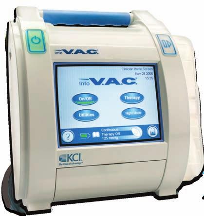
10 INFOV.A.C. Therapy Unit - Parts Identification Power On/Off Button Canister Release Button Touch Screen User Interface INFOV.A.C. 500mL Canister Memory Card Slot Clinician Use Only Stylus Data Door Infrared (IR) Data Port (Available on some units, Clinician Use Only) USB Data Port Clinician Use Only Carry Handle Battery Charging Indicator Light Hanger Knob Hanger Arm Power Connection INFOV.A.C. Power Supply 4

 to power the device or to recharge the battery.")


11 Preparation for Use Before preparing the INFOV.A.C. Therapy Unit for use, inspect the unit for any damage or contamination. Refer to the Care and Cleaning section of this manual for more information. Charging the Battery The INFOV.A.C. Therapy Unit comes with its own power supply and rechargeable battery. The battery is not user accessible or serviceable. The power supply has a two-part cord; one that plugs into a AC wall outlet and one that plugs into the INFOV.A.C. Therapy Unit. The AC power cord may have different wall plug configurations depending on country requirements. Use only the power supply provided with the INFOV.A.C. Therapy Unit (part number M ) to power the device or to recharge the battery. Using any other power supply may damage the INFOV.A.C. Therapy Unit. To isolate the therapy unit from supply mains, unplug the AC power from the wall outlet. Power cords and tubing may present a tripping hazard. Ensure that all cords and tubing are out of areas where people may walk. 1. Plug the AC power cord into the power supply. 2. Plug the AC power cord into an AC wall outlet. 3. Locate the white arrow on the INFOV.A.C. power supply charging cord connector. 4. Plug the INFOV.A.C. power supply charging cord connector into the power connection on the back of the INFOV.A.C. Therapy Unit with the white arrow facing up. It should take approximately four hours to fully recharge the battery. The system can be used while the battery is recharging. To maximize battery life, keep the unit plugged in. 5
12 Battery Charging Indicator Light When the INFOV.A.C. power supply is correctly plugged into the INFOV.A.C. Therapy Unit, the battery charging indicator light on the back of the unit will glow amber as the battery is charging. When the battery is fully charged the battery charging indicator light will glow green. The battery level is shown on the bottom of the touch screen user interface: Fully Charged In Use Battery Low, charge battery soon 6


13 Attaching the INFOV.A.C. Therapy Unit to an IV Pole 1. Ensure the hanger arm is in the horizontal position. 2. Hold the INFOV.A.C. Therapy Unit by the carry handle, grip the hanger knob and pull the hanger arm out. 3. Place the hanger around the IV pole ensuring that the pole is in the vertical rubber groove on the rear of the INFOV.A.C. Therapy Unit. Allow the hanger to close pulling the therapy unit onto the pole. 4. Turn the hanger knob to lock the hanger arm in place. The lock symbol on the hanger knob will align with the arrow on the therapy unit when the mechanism is locked. An audible click also indicates that the mechanism is locked. The hanger knob can be turned past the lock position to further secure the INFOV.A.C. Therapy Unit. Hand tighten only; excessive force or tools should not be used. 7


14 Attaching the INFOV.A.C. Therapy Unit to a Bed Footboard 1. Ensure the hanger arm is in the vertical position. 2. Hold the INFOV.A.C. Therapy Unit by the carry handle, grip the hanger knob and pull the hanger arm out. 3. Place the hanger over the footboard. Allow the hanger to close pulling the therapy unit onto the footboard. 4. Turn the hanger knob to lock the hanger arm in place. The lock symbol on the hanger knob will align with the arrow on the therapy unit when the mechanism is locked. An audible click also indicates that the mechanism is locked. The hanger knob can be turned past the lock position to further secure the INFOV.A.C. Therapy Unit. Hand tighten only; excessive force or tools should not be used. Releasing the INFOV.A.C. Therapy Unit from an IV Pole or Bed 1. Hold the INFOV.A.C. Therapy Unit by the carry handle. 2. Reverse the attaching procedure. 8


15 Installing the 500mL and 1000mL Canisters 1. Press Power On/Off to turn the INFOV.A.C. Therapy Unit on. 2. Attach the canister: Slide the canister into the end of the INFOV.A.C. Therapy Unit as shown below. Push the canister firmly into place. An audible click signals the canister is correctly installed. 3. Connect the canister tubing to the dressing tubing: Push the connectors together and twist until the locking tabs are fully engaged. 4. Open all tubing clamps as shown below. Closed Clamp Open Clamp 9


16 Changing the 500mL and 1000mL Canisters A canister may be changed under routine conditions or under alarm conditions. Under routine conditions the Canister Release button will NOT be flashing. When changing the canister under routine conditions do NOT turn power off to the INFOV.A.C. Therapy Unit. Under alarm conditions the Canister Release button will be flashing. An alarm screen will be displayed and therapy will be off. WARNING: According to clinician instructions, replace V.A.C. Dressing with alternate dressing if therapy is interrupted or off for more than two hours. On/Off 1. Stop therapy by pressing the Therapy On/Off button on the touch screen user interface. 2. Close all tubing clamps as illustrated. 3. Disconnect the canister tubing from the dressing tubing: Twist connectors until the locking tabs are fully disengaged and pull the connectors apart. 10


17 Changing the 500mL and 1000mL Canisters (cont) 4. Press the Canister Release button. The canister will eject but remain in the cradle. 5. Lift the canister out of the cradle. 6. Dispose of the canister according to institution and / or local environmental regulations. WARNING: According to clinician instructions, replace V.A.C. Dressing with alternate dressing if therapy is interrupted or off for more than two hours. 11


18 Installing the 300mL ACTIV.A.C. Canister 1. Attach the canister: Push the canister firmly into place on the INFOV.A.C. Therapy Unit as illustrated below. 2. Connect the canister tubing to the dressing tubing: Push the connectors together and twist until the locking tabs are fully engaged. 3. Open all tubing clamps as illustrated. Closed Clamp Open Clamp 12
19 Removing the 300mL ACTIV.A.C. Canister Operating Instructions When the Canister Release button is pressed, the 300mL canister is NOT held in place by the cradle of the INFOV.A.C. Therapy Unit. When removing the 300mL canister from the INFOV.A.C. Therapy Unit ensure that the canister is held FIRMLY before pressing the Canister Release button. 1. Hold the canister firmly. 2. Press the Canister Release button. Before powering the therapy unit on, ensure that: Powering the INFOV.A.C. Therapy Unit On / Off The V.A.C. Dressing is applied as described in the Application Instructions supplied with the V.A.C. Dressing. The INFOV.A.C. Canister is attached as described in the Installing the Canisters sections of this manual. The INFOV.A.C. Therapy Unit is fitted to an IV pole or footboard or placed as described in the Preparation for Use section of this manual. Power On: 1. Connect the INFOV.A.C. Therapy Unit to the power supply as described in the Preparation for Use section of this manual. 2. Press and hold the Power On/Off button for approximately two seconds to turn the INFOV.A.C. Therapy Unit on. The Power On/Off button will illuminate and the touch screen user interface will activate. The INFOV.A.C. Therapy Unit start up process will briefly be displayed followed by a Warning Screen. Power Off: Press and hold the Power On/Off button for approximately two seconds to turn the INFOV.A.C. Therapy Unit off. The Power On/Off button will flash for ten seconds after which the INFOV.A.C. Therapy Unit will automatically shut down. WARNING: According to clinician instructions, replace V.A.C. Dressing with alternate dressing if therapy is interrupted or off for more than two hours. 13
20 Operating the Touch Screen The touch sensitive screen on the front of the unit displays information on current system operations and settings, and provides an interface for changing settings and operation. The operation of the touch screen is detailed in the following pages. The touch screen should ONLY be operated by finger or the supplied stylus (see INFOV.A.C. Therapy Unit Parts Identification section). Using pens or pointing devices will damage the screen and may affect the proper function of the unit. Control Screens The three levels of Control Screens are Patient Mode, Clinician Mode and Restricted Mode. Patient Mode The clinician may select Patient Mode to allow a patient to control certain elements of their therapy. This mode does not allow the patient to access or alter therapy settings. The patient can activate Night Mode and the Screen Guard, access the Help screens, and respond to alarms. Clinician Mode The Clinician Mode screens allow a clinician to set and change therapy settings, view therapy history and access the Restricted Mode (see below). Restricted Mode (Patient History) The Restricted Mode screens allow access to patient wound images, image area trend charts and other patient health information that the caregiver has entered. From this mode the clinician can adjust the Leak Alarm sensitivity, and export therapy and patient histories. A secure password system protects the Restricted Mode from unauthorized access. The secure password is created by the healthcare professional, not KCI. If a new password is created, all patient history associated with the previous password is deleted. All information is automatically deleted when therapy unit is returned to KCI. 14
21 Patient Mode Control Screens Audio Pause Indicator with countdown timer 58:23 Patient Home Screen 11 Jan :06 Mode Indicator, Current Date, Current Time Start or Stop V.A.C. Therapy Battery Level Indicator Help Button On/Off Night Mode Activate Night Mode Therapy Status Bar and Display Area Screen Guard Plug icon appears when plugged into a wall outlet. Appears in the Therapy Status Bar and Display Area when a Patient Record is active. Icon rotates when INFOV.A.C. Therapy Unit is applying negative pressure. A lighted green crescent means the function is on. An unlit crescent means the function is off. Common Screen Control Buttons Navigation Buttons Press to access Help Menu. Press to activate Screen Guard feature to help prevent unintentional screen changes. This feature should be used when cleaning the touch screen. To release the Screen Guard, press 1 and then 2, which will appear on the screen when Screen Guard is active. Press to leave the current screen. Cancel Next Press to stop action in progress. Press to go to the next screen. OK Press to acknowledge the action is complete and display the next screen. Back Press to return to the previous screen. + _ Press to scroll through available selections. Press and hold to scroll rapidly. 15
22 Night Mode Function Patient Home Screen 11 Jan :06 The Night Mode function on the Patient Home Screen can be used to dim disrupting lights from the therapy unit during nighttime therapy use. On/Off Night Mode Night Mode Press to activate the Night Mode function from the Patient Home Screen. A confirmation screen will be displayed before Night Mode is immediately activated. When the Night Mode function is active, therapy continues as normal. The touch screen user interface will darken and the green Power On/Off button will dim. The Night Mode function will deactivate in the event of an alarm. Patient Home Screen 11 Jan :06 During Night Mode, the screen will illuminate when touched and display the Patient Home Screen. On/Off Night Mode Should the touch screen user interface be touched while night mode is active, the screen will automatically darken after two minutes of inactivity. Night Mode Press to deactivate the Night Mode function. 16
23 Patient Mode Help Menu Screen Help Menu Operating Instructions Language Clinician Mode About Operating Instructions About Press to access the Patient Mode Help Menu screen from any Patient Mode screen where this button appears. Press to access Operating Instructions. Press to access the About screen for information regarding the INFOV.A.C. Therapy Unit software. Clinician Mode Press to access Clinician Mode (press and hold for three seconds). Language Press to access the Language screen to select the appropriate language. Press to return to the Patient Home Screen. Operating Instructions Screen Operating Instructions The Operating Instructions provide help in operating the INFOV.A.C. Therapy Unit. Cleaning Operation Alarms Operating Instructions Press to access the Operating Instructions screen from the Help Menu screen to view basic instructions for operation, cleaning and alarms. 17
24 Clinician Mode Control Screens Clinician Home Screen 11 Jan :06 Mode Indicator, Current Date, Current Time Start or Stop V.A.C. Therapy On/Off Therapy Access the Therapy screen Access the Utilities screen Battery Level Indicator Help Button Plug icon appears when plugged into a wall outlet. Utilities Night Mode Appears in the Therapy Status Bar and Display Area when a Patient Record is active. Activate Night Mode Therapy Status Bar and Display Area Screen Guard Icon rotates when INFOV.A.C. Therapy Unit is applying negative pressure. A lighted green crescent means the function is on. An unlit crescent means the function is off. Common Screen Control Buttons Press to access Clinician Mode Help Menu. Press to activate Screen Guard feature to help prevent unintentional screen changes. This feature should be used when cleaning the touch screen. To release the Screen Guard, press 1 and then 2, which will appear on the screen when Screen Guard is active. To Return to the Patient Home Screen Press the Help button. Patient Mode Press Patient Mode on the Help Menu screen. OK Press and hold OK until the Patient Home Screen returns. 18
25 Therapy Start Screen Therapy Start Leak Rate High Log On/Off From the Clinician Home Screen press Therapy On/Off to access the Therapy Start screen. Low Seal Audio A green bar graph indicates that the INFOV.A.C. Therapy System is operating normally. Ensure that a new V.A.C. Dressing has been applied and therapy settings have been selected per physician s orders before starting therapy. From this screen the clinician can use the SEAL CHECK Feature to view the integrity of the V.A.C. Dressing, or use the Log tool to record a canister change or record the number of foam pieces used during a dressing change. SEAL CHECK Feature Overview The SEAL CHECK Feature is used to help find negative pressure leaks. The SEAL CHECK Feature includes: an audible tone that changes frequency as the rate of the leak changes. Pressing the Seal Audio button will switch between the audible tone being on or off. a real time bar graph that gives a visual indication of the rate of the leak. Access the SEAL CHECK Feature three different ways: When Therapy is started from the Clinician Home Screen, discussed on the following pages. When the SEAL CHECK Button is pressed on the Therapy screen. When the SEAL CHECK Button is pressed on the Leak Alarm screen after the INFOV.A.C. Therapy Unit detects a possible leak. Patients only have access to the SEAL CHECK Feature through the Leak Alarm screen when the INFOV.A.C. Therapy Unit detects a possible leak. 19
26 How to Use the SEAL CHECK Feature (When Starting Therapy) Therapy Start Leak Rate High Log Seal Audio On/Off From the Clinician Home Screen press Therapy On/Off to access the Therapy Start screen. SEAL CHECK Feature Turn the Seal Audio tone On or Off Low Line on bar graph is the transition point from green to orange and vice-versa. An orange bar graph indicates a significant leak. The SEAL CHECK Feature provides an audible tone and bar graph to assist in finding leaks. The frequency of the audible tone and the height of the bar graph will reflect the leak rate. The audible tone slows down and the bar graph decreases in height as the leak is found and corrected. During initial dressing draw down, the bar graph should turn orange and then return to green if there are no significant leaks. Most leaks occur in three specific areas. where the V.A.C. Drape meets the skin. where the SENSAT.R.A.C. Pad is attached to the V.A.C. Drape. at tubing connections. Finding a Leak Using the SEAL CHECK Feature 1. Ensure connector between dressing tubing and canister tubing is properly locked. 2. Ensure the canister is securely installed on the therapy unit. If the canister is properly installed, the canister cannot be removed by gently pulling the canister directly away from the unit. 3. While therapy is on, apply gentle pressure and move your hand and fingers slowly around the edges of the drape and SENSAT.R.A.C. Pad. The bar graph will lower and the frequency of the audible tone (if Seal Audio is on) will decrease when the leak is found. 4. Refer to the Application Instructions provided with V.A.C. Dressings for information on using excess V.A.C. Drape material to seal the leak area. 5. When finished press to return to the Clinician Home Screen. 20
27 Log Tool Overview The Log tool can be used to track: the number of foam pieces used during a dressing change. canister changes. Logged information is viewable and exportable on the Therapy History screens. How to Use Log Tool (When Starting Therapy) Item to Log Log From the Clinician Home Screen press Therapy On/Off then Log to access the Item to Log screen. Canister Dressing For dressing, also note the No. of foam pieces in patient chart and on drape. Canister Dressing Press to log the time and date of a canister replacement. Press to log the number of foam pieces used in a dressing change. Press to return to the Clinician Home Screen. Canister Replaced Screen Canister Replaced Press OK to log that the canister has been changed Canister From the Clinician Home Screen press Therapy On/Off then Log, then Canister to access the Canister Replaced screen. (Will use the current time and date) Cancel OK OK Cancel Press to log that the canister has been replaced and return to the Item to Log screen. The current time and date will be recorded. Press to return to the Item to Log screen without logging an entry. 21
28 Number of Foam Pieces Screen Number of Foam Pieces Press OK to log number of foam pieces and time/date 2 Cancel 6 Last recorded on 01 Jan 2010 OK + _ Dressing From the Clinician Home Screen press Therapy On/Off then Log, then Dressing to access the Number of Foam Pieces screen. Information displayed represents the last logged entry. + _ Use the + and - buttons to select the number of pieces of foam used during the current dressing change. OK Press to log the number of foam pieces used and return to the Item to Log screen. The current time and date will be recorded. Cancel Press to return to the Item to Log screen without logging an entry. Always document the number of foam pieces used in patient chart and on the V.A.C. Drape. Logged information will appear in Therapy History as follows: dd/mmm/yy Time Event 11/Jan/10 15:54 Canister Changed 11/Jan/10 15:55 Dressing Changed, 4 The numeral after Dressing Changed is the number of foam pieces recorded on the above screen. 22
29 Therapy Screen The Therapy screen enables clinicians to change settings, select wound type, check the seal and view the therapy or patient history. Therapy Therapy From the Clinician Home Screen press Therapy to access the Therapy screen. Settings Settings Guide Settings Press to manually set therapy. SEAL CHECK TM Therapy History Patient History Settings Guide Seal Check TM Press to access the settings guide for preset therapy settings. Press for assistance in finding leaks. Therapy History Press to view or export therapy history. Patient History Press to view or export patient history from the Enter Access Code screen. Settings Screen (Manual) Settings Settings From the Clinician Home Screen press Therapy, then OK, then Settings to access the Settings screen. Pressure Intensity Pressure Press to change pressure settings. Continuous Intermittent Intensity Continuous Press to change intensity. Press to toggle between Continuous and Intermittent therapy. Intermittent Press to set Intermittent therapy times. 23
30 Pressure Screen Pressure Pressure From the Clinician Home Screen press Therapy, then OK, then Settings then Pressure to access the Pressure screen. + _ + _ Use the + and - buttons to change the desired pressure. Pressure can be set from 25 to 200 mmhg in increments of 25 mmhg. Press to go to the Confirm screen. Default setting is: (accuracy + / - 10 mmhg). Intensity Control From the Clinician Home Screen press Therapy, then OK, then Settings to access the Intensity button. Intensity is related to the time it takes to reach the target therapy level after the initiation of therapy. The lower the intensity setting, the longer it will take for the target therapy level to be reached. KCI recommends that new patients begin therapy at the lowest intensity setting as this allows for slower increase of negative pressure once the foam is compressed in the wound. The intensity can remain at the minimum setting throughout the entire length of treatment, if desired. Press to change levels. Green crescent changes with each setting. Intensity Low Intensity Medium Intensity High Default setting is: Low. 24
31 Intermittent Screen Intermittent On Time + + Off Time 5 2 Minutes Minutes From the Clinician Home Screen press Therapy, then OK, then Settings, then Intermittent to access the Intermittent screen. + _ Use the + and - buttons to change the desired On and Off Time (in minutes). Both On and Off Times can be set from 1 minute to 10 minutes in 1 minute increments. Press to go to the Confirm screen. Changing Intermittent time intervals will take effect in the next cycle. Default setting is: On Time = 5 minutes, Off Time = 2 minutes. Settings Confirmation Confirm Wound Type: Pressure Mode: Intensity: Back Chronic Ulcers Low Cancel OK Press when finished with the Settings screen to continue to the Confirm screen. If the displayed settings are as desired, press OK to continue to the Clinician Home Screen. Otherwise, press Back to change any incorrect settings. If settings were changed with V.A.C. Therapy off, press the Therapy On/Off button on the Clinician Home Screen to start therapy. 25
32 Settings Guide The Settings Guide helps the clinician select from pre-set therapy ranges according to wound type and treating physician s orders. Selected ranges are a guide based on common settings for different wound types. Individual patient conditions may vary. Consult physician to verify settings for each patient. Should physician orders fall outside the pre-set therapy ranges, select Other in this mode or use Manual Therapy Settings detailed in the Settings Screen (Manual) section of this manual. Select Wound Type Screen Select Wound Type Chronic Ulcers Back + _ Cancel Next From the Clinician Home Screen press Therapy, then OK, then Settings Guide, then OK to access the Select Wound Type screen. + _ Use the + and - buttons to scroll through the available wound type selections. Cancel Press Cancel on any screen to cancel and exit the procedure. Select Pressure Screen Select Pressure Within available range. Cancel When finished with the Select Wound Type screen, press Next to continue to the Select Pressure screen. + _ + _ Use the + and - buttons to scroll through the pressure selections. Back Next Pressure selections are in ranges for the wound type selected on the previous screen. 26
33 Select Mode Screen Select Mode Cancel When finished with the Select Pressure screen, press Next and move to the Select Mode screen. Intermittent + _ + _ Use the + and - buttons to choose Continuous or Intermittent Therapy. Back Next Next When finished with this screen, press Next. If Intermittent is not an option for the wound type selected, the mode will not change. Intermittent can be manually set from the Settings screen, or press Back and select Other as the wound type. Intermittent Type Screen Intermittent Cancel If Intermittent Therapy was chosen on the previous screen, this screen will appear. On Time + + Off Time 5 2 Minutes Minutes + _ Use the + and - buttons to change the desired On and Off Time (in minutes). Back Next Both On and Off Times can be set from 1 minute to 10 minutes in 1 minute increments. Next When finished with this screen, press Next. Default is: On Time = 5 minutes, Off Time = 2 minutes. Settings Guide Confirmation Confirm Wound Type: Pressure Mode: Intensity: Back Chronic Ulcers Low Cancel OK Once the settings are chosen, the Confirm screen will appear. If the displayed settings are as desired, press OK to continue to the Therapy Screen. Otherwise, press Back to change any incorrect settings. Settings take effect when OK is pressed. Settings Guide Intensity default is Low. Intensity can only be changed using the Manual Therapy Settings (see Settings Screen (Manual) section). 27
34 SEAL CHECK Screen SEAL CHECK Leak Rate High The SEAL CHECK screen provides a visual and audible representation of the air flow rate in the SENSAT.R.A.C. system. For more information about the SEAL CHECK Feature see SEAL CHECK Feature Overview section. Low Seal Audio Seal Check TM From the Clinician Home Screen press Therapy, then OK, then SEAL CHECK Button to access the SEAL CHECK Feature screen. Seal Audio Press Seal Audio to turn the Seal Audio tone on or off. This tool can be used as an aid to ensure that the dressing system is correctly sealed. Therapy History Screen Therapy History + _ Date Time Event 18 Dec :41:20 Low Intensity 18 Dec :41:20, Intermittent 5 18 Dec :41:20 (Clinician M 18 Dec :20:00 Therapy Inactive (Clinici 18 Dec :04:59 Unit On (Clinician Mode) 17 Dec :51:51 Unit Off (Clinician Mode) The Therapy History screen displays the therapy information in date, time and event columns. The date is in ascending order and time is displayed using the 24 - hour clock format. Therapy History + _ From the Clinician Home Screen press Therapy, then OK, then Therapy History to access the Therapy History screen. Use the + and - buttons to scroll to additional listings. If wound history is recorded, see Patient History screen for wound progress history. Press to return to the Therapy screen. Patient History Screens The Patient History screens enable a clinician to: Create a new access code. Delete the current patient record. Start a new patient record. View the patient record. Export history. View a wound image area graph. Analyze wound images. 28
35 Enter Access Code Screen Enter Access Code (4 Char Max) **** Create Del 0 Cancel OK Patient History OK Create Cancel From the Clinician Home Screen press Therapy, then OK, then Patient History to access the Enter Access Code screen. Press to proceed to the next screen. Press to create a new access code. Press to return to the Therapy screen. This icon appears in the Therapy Status Bar and Display Area when a Patient Record is active. For security purposes: The INFOV.A.C. Therapy Unit will only allow one patient record at a time to be active. If a new access code is entered, the current access code is overwritten and all patient history associated with it is deleted. All information will be automatically deleted when the unit is returned to KCI. If a current access code is incorrectly entered, access to the Patient History screen will be denied and you will automatically be returned to the Therapy screen. If an incorrect access code is entered ten times, the system will lock. Contact your local KCI representative. Enter Access Code (4 Char Max) **** Create Del 0 Cancel OK To create a new access code: Create 1. Press Create. OK 2. Enter your four digit numerical access code using the numbers on the screen, then press OK. 3. Re-enter your four digit numerical access code. OK 4. Press OK to set the new access code and proceed to the Change Patient ID screen. 29
36 Change Patient ID Screen A unique number is automatically generated from the date and time unless a custom ID is created. Change Patient ID (Use stylus on keys) 1. Enter the new Patient ID on keyboard if desired. CAP _ <- Q W E R T Y U I O P A S D F G H J K L Z X C V B N M,. OK OK 2. Press OK when you have entered the new Patient ID, or are ready to proceed to the Patient History screen. 3. Press to continue to the Confirm screen. Press this button as a space bar. <- Press this button to backspace/delete. If no changes are made, the automatically generated number will be used as the Patient ID. Patient History Screen Patient History View History Delete History Export History Patient History From the Clinician Home Screen press Therapy, then OK, then Patient History, then enter or create an access code and press OK to access the Patient History screen. View Graph Alarm Adjust Imaging View History Press to view Patient History and add notes (up to 30 characters). Delete History Press to delete a Patient History file. Export History Press to export Patient History and Therapy History. View Graph Press to view a graphical representation of measured wound area over time. Alarm Adjust Press to adjust Leak Alarm settings. Imaging Press to view and perform Wound Image Analysis. 30
37 View History Screen Patient History + Add Note _ Add Note To History Screen Date Time Event 18 Dec :42:30 Dsc_0002.jpg 18 Dec :12:00 Transferred Image 18 Dec :41:20 Area = cm 2 18 Dec :20:00 ID = P phi Add Note To History (Use stylus on keys) CAP <- Q W E R T Y U I O P A S D F G H J K L Z X C V B N M,. Add Note View History Add Note From the Clinician Home Screen press Therapy, then OK, then Patient History, then enter or create an access code and press OK, then View History to access the Patient History screen. The Patient History screen will display short notes (up to 30 characters) added by the clinician and/or medical staff. For a new Patient History this screen will be blank. From the Clinician Home Screen press Therapy, then OK, then Patient History, then enter or create an access code and press OK, then View History then Add Note on the Patient History screen to open the Add Note to History screen. Use the screen keys to enter a note (up to 30 characters). The notes entered will be displayed in the window area above the keys. Add Note Press to log new note and return to Patient History screen. Press this button as a space bar. <- Press this button to backspace/delete. Press to return to the Patient History screen. Delete History Screen Delete History To delete current patient history press Delete. Once deleted, the data cannot be recovered. Press Cancel to abort delete history operation. Cancel Attention! Delete Delete History Delete Cancel From the Clinician Home Screen press Therapy, then OK, then Patient History, then enter or create an access code and press OK, then Delete History to access the Delete History screen. Deleted History cannot be recovered. Press and hold Delete for two seconds to delete the Patient History Records. After the Patient History Records have been deleted, the screen will return to the Therapy screen. Press to return to the Patient History screen without deleting Patient History. All information will be automatically deleted when the unit is returned to KCI. 31


.")
38 Export Patient History Screen Export Patient History Export Patient History Export to Memory Card Export To USB Export To IR Export To USB Export to Memory Card Data is exported with allocated filename. Data is exported with allocated filename. If Unit has an IR Port If Unit Does Not Have an IR Port Export History From the Clinician Home Screen press Therapy, then OK, then Patient History, then enter or create an access code and press OK, then Export History to access the Export Patient History screen. The exported Patient History includes folders containing Therapy History, Patient History and all wound images for the current patient. Image files are exported with the file names created during the imaging process. Files can be exported to a Memory Card, USB device or IR Port (if unit is equipped). Export to Memory Card Access the Memory Card Transfer screen. Export To USB Access the USB Transfer screen. Export To IR Access the IR Transfer screen. USB Data Port Infrared Data Port (if equipped) Memory Card Slot The connection ports are for clinician use only. 32
39 Memory Card Transfer Screen The Memory Card Slot is for authorized clinician access only. 1. Insert the Memory Card into the INFOV.A.C. Therapy Unit Memory Card Slot. An audible click signals that the card is properly inserted. Memory Card Transfer Please insert memory card into the memory card slot located at the front of the InfoV.A.C. therapy unit then select Next Cancel Next Export to Memory Card From the Clinician Home Screen press Therapy, then OK, then Patient History, then enter or create an access code and press OK, then Export History, then Export to Memory Card to access the Memory Card Transfer screen. Next 2. Press Next to continue. A progress bar on the screen will indicates transfer status. OK 3. When the transfer is complete press OK to continue. If the Memory Card Transfer Error screen appears when the Memory Card is inserted into the Memory Card Slot, files could not be transferred. Possible reasons for transfer error: Card not inserted correctly. Incorrect format card. No images in the system. 33


40 USB Transfer Screen The USB port is for authorized clinician access only. USB devices should be connected directly and only unpowered USB mass storage devices should be attached to the INFOV.A.C. Therapy Unit. AC or battery powered drives, computers, computer equipment, other devices or USB extension leads should not be connected to this device. 1. Insert the USB device into the INFOV.A.C. Therapy Unit USB port. USB Transfer Insert USB flash drive into the USB port located on the front of the INFOV.A.C. therapy unit, and select Next. Note: only connect KCI approved memory devices to the USB port. Export To USB From the Clinician Home Screen press Therapy, then OK, then Patient History, then enter or create an access code and press OK, then Export History, then Export to USB to access the USB Transfer screen. Cancel Next Next 2. Press Next to continue. A progress bar on the screen will indicates transfer status. OK 3. When the transfer is complete press OK to continue. If the USB Transfer Error screen appears when the USB device is inserted into the USB port, files could not be transferred. Possible reasons for transfer error: The USB device is not inserted correctly. The incorrect type of device is connected. 34
41 IR Transfer Screen IR Transfer Open data door on InfoV.A.C. therapy unit, place IR device in front of IR window and select Next Cancel Next The Infrared Data Port is for authorized clinician access only Some units may not be equipped with this port. Please refer to Export Patient History section for alternate methods of data transfer. Export To IR From the Clinician Home Screen press Therapy, then OK, then Patient History, then enter or create an access code and press OK, then Export History, then Export to IR to access the IR Transfer screen. 1. Open the Data Door and position the IR device in front of the INFOV.A.C. Therapy Unit. 2. Aim the IR Data Port of the transfer device at the Infrared Data Port on the INFOV.A.C. Therapy Unit. Next 3. Press Next to continue. The INFOV.A.C. Therapy Unit will attempt to establish a connection with the transfer device; once the connection is established, the transfer will begin. A progress bar on the screen will indicates transfer status. OK 4. When the transfer is complete press OK to continue. If the IR Transfer Error screen appears, the INFOV.A.C. Therapy Unit does not detect the IR device or the device is incompatible. Files could not be transferred. Possible reasons for transfer error: The IR transfer device is not lined up with INFOV.A.C. Therapy Unit's Infrared Data Port. The IR transfer device s IR port is not active or is not set to receiving mode. Lenses on the IR device are damaged or obscured. 35
42 Graph Screen Graph Measured Image Area: Area (cm 2 ) Dec 2009 Time (days) Dec 2009 View Graph From the Clinician Home Screen press Therapy, then OK, then Patient History, then enter or create an access code and press OK, then View Graph to access the Graph screen. The graph displays a representation of image area over time. A graph cannot be constructed if the Patient History file has been deleted. A graph cannot be constructed unless measurements of the image area have been previously saved in the patient s history log. At least two measurements from different days are required (area of the image against time) for a graph to be constructed. Select Leak Alarm Threshold Screen Select Leak Alarm Threshold Cancel Consult the clinician prescribing therapy before making changes to this setting. High Note High is the default value + _ OK Alarm Adjust + _ From the Clinician Home Screen press Therapy, then OK, then Patient History, then enter or create an access code and press OK, then Alarm Adjust to access the Select Leak Alarm Threshold screen. Use the + and - buttons to select the level of alarm adjustment required. The Leak Alarm Threshold is set by default to High (2 Liters per minute), this screen allows a change to Low (1 Liter per minute) when appropriate. OK Press to confirm the alarm adjustment settings. 36
43 Wound Image Analysis The Wound Imaging feature is an aid in recording treatment progress. Wound imaging area and volume calculation features are not intended to be exact measurements and are not intended for use in the diagnosis and treatment of wounds. Accessories required to utilize this feature include: Digital camera that uses an SD/MMC card. The maximum size of the SD/ MMC card that can be used to upload images to an INFOV.A.C. Therapy Unit is 2 GB. The unit will not upload images using a SD/MMC card larger than 2 GB. Please check the size of the SD/MMC card prior to uploading images into the INFOV.A.C. Therapy Unit. The maximum picture resolution accepted by the INFOV.A.C. Therapy Unit is 2.2 megapixels. If using a camera with higher resolution, you must adjust the picture resolution settings on your camera to a setting of 2.2 megapixels or less. Please refer to your camera user manual for further instructions. An SD/MMC card. Calibration Reference Square. This is found on the ruler in the V.A.C. Dressing package. This reference square is needed for the INFOV.A.C. Therapy Unit to calculate wound measurements. Calibration Square Stylus. This is found inside the data door (see INFOV.A.C. Therapy Unit - Parts Identification section). This is needed for tracing. For optimal operation of the Wound Image Analysis feature it is recommended that: The sterile Calibration Reference Square should be placed in the same location on the wound each time an image is taken. All images be taken from directly above the wound. The wound and Calibration Reference Square should fill as much of the image as possible. The image should be taken in good light conditions. Images must be taken directly from the camera, not transferred or downloaded to the card from a computer. Using a camera that has a date and time function will allow for easier tracking of images. 37
44 Troubleshooting Suggestions: Media Image Capacity: Keep as few images on the media as possible prior to uploading the images into the INFOV.A.C. Therapy Unit. It is recommended you upload any existing pictures from your media (SD/MMC card or USB memory stick) to your computer prior to capturing new wound photos on the media. By having too many images on the media, you run the risk of receiving a DSP Not Initialized error which will freeze the unit, preventing image upload. DSP Not Initialized Error: This indicates an issue with the image uploading and prevents the unit from uploading images into the INFOV.A.C. Therapy Unit. If you receive this error, exit to the previous screen and reset the unit by turning the unit off and back on again. If you cannot go back to the previous screen, reset the unit by turning the unit off and back on again. You may then proceed to the image uploading screen as directed in this manual (see Imaging Screen section). Screen Freezes during Image Uploading: This indicates an issue with the image uploading into the INFOV.A.C. Therapy Unit. If you receive this error, reset the unit by turning the unit off and back on again. You may then proceed to the image uploading screen as directed in this manual (see Imaging Screen section). Erasing Images from the Unit: Digital images cannot be individually erased from the INFOVAC. Therapy Unit. When the internal memory is full and more pictures need to be uploaded, the patient history must be cleared by deleting the record and creating a new patient history. It is recommended that the patient history record be exported prior to deleting so all history and images are saved. See Patient History Screens section of this manual for further instructions on viewing, deleting, exporting, and creating a patient history record. 38
45 Imaging Screen Imaging INFOV.A.C. Memory Select the device you want to view images from Imaging From the Clinician Home Screen press Therapy, then OK, then Patient History, then enter or create an access code and press OK, then Imaging to access the Imaging screen. USB Memory Device Memory Card Memory Card Press to select and view an image from the SD/MMC card. USB Press to select and view an image from a USB device. INFOV.A.C. Memory Press to select and view an image from the INFOV.A.C. Therapy Unit internal memory. There will be a short delay while the images are accessed from the internal memory or the memory card. The relevant button will be highlighted with a green rim to indicate that this is in progress. When the INFOV.A.C. Therapy Unit is ready, the File Select screen will appear. If INFOV.A.C. Memory is selected for a new Patient Record, no images will be available and the image thumbnail will be black. 39
46 File Select Screen File Select 9 of 10 + The number of files available for viewing and the number of the currently-viewed file (for example, 9 of 10) is displayed in the upper right of the File Select screen. filename.jpg Select _ + _ 5. Use the + and - buttons to select the next or the previous image. Select 6. Press Select when the required image is displayed. Images being opened from a memory card or USB device will be automatically downloaded into the INFOV.A.C. Therapy Unit internal memory. Press to begin the Wound Area Trace procedure. Press to calculate the wound area inside the highlighted trace outline. Press to begin the Wound Volume calculation procedure. 40
47 Image Reference Calibration Trace the reference square in the image to scale the image area and volume measurements. On-screen instructions are provided at the bottom of each screen to guide the user through the process Press highlighted button to mark up the reference square. Use only the stylus provided to trace the reference square. Press to begin the Calibration Reference process. Touch each corner of the reference square. When the last corner of the reference square is touched the corner points will be joined by a highlighted line Wound Area Trace It is important to select corners in either a clockwise or counter-clockwise manner. Incorrect sequence will lead to a calibration error. If necessary, press to restart the Calibration Reference process. Next, trace the outline of the wound area. Press the button pictured at left to begin the Wound Area Trace procedure. The Select Image Area screen will appear. Select Image Area Select the image area you would like to trace. Image Area 2 Image Area 1 Image Area 3 Image Area 1 Image Area 2 Press Image Area 1 to trace the overall outline of the wound area. All traces and results for Image Area 1 will be displayed in yellow. The INFOV.A.C. Therapy Unit only stores the area and depth of Image Area 1 in the Patient Log. This information in the Patient Log is used to construct a graph. Press Image Area 2 to trace another area inside the wound. All traces and results for Image Area 2 will be displayed in blue. Image Area 3 Press Image Area 3 to trace an additional area. All traces and results for Image Area 3 will be displayed in pink. 41
48 Once an Image Area is selected, the image will be displayed as a full screen. Draw around the required area with the stylus. A yellow square will appear at the start point. The trace is completed when the end of the yellow line returns to the start point. To correct an error, tap the stylus in the square at the start point. This action will return you to the previous screen where you can select to retrace the area. When the outline of the wound image area is complete, the buttons will reappear. If required, press Wound Trace Area button again to trace additional areas. Calculate Wound Area Area= cm 2 Press the button pictured at left to calculate the wound area inside the highlighted trace outline. The results will be displayed in the color of the trace for the appropriate measured area. Press highlighted button to calculate the area(s) traced. 42
49 Calculate Wound Volume Select Image Area for Depth Screen Select Image Area for Depth Select the image area you would like to calculate the volume. Image Area 1 Image Area 2 Image Area 3 The wound volume can be calculated from the areas previously traced and the measured depth. Press the button pictured at left to begin the Wound Volume calculation procedure. The Select Image Area for Depth screen will appear. Image Area 1 Press to enter the depth of Image Area 1. The INFOV.A.C. Therapy Unit only stores the area and depth of Image Area 1 in the Patient Log. This information in the Patient Log is used to construct a graph. Image Area 2 Press to enter the depth of Image Area 2. Image Area 3 Press to enter the depth of Image Area 3. Enter Image Area Depth cm Del. 0 OK Use the screen keys to enter the image depth. OK Press OK when finished entering image depth. Area= cm 2 Volume = cm 3 Image area and volume will be displayed on the screen at left. Press to return to the Patient History screen. 43
50 Clinician Utilities Utilities Utilities From the Clinician Home Screen, press Utilities to access the Utilities screen. Time/Date Brightness Regional Settings From this Utilities screen the clinician can: Set the time and date to current time and calendar date. Adjust regional settings. Set the brightness of the touch screen user interface. The green crescent at the bottom of the button indicates the level of brightness: Brightness Low Brightness Medium Brightness High The Default setting is Medium Press to return to the Clinician Home Screen. Changing Time and Date Set Time/Date Year Month Day Hour (24) Minute 2009 Dec Time/Date + - From the Clinician Home Screen press Utilities, then press Time/Date to access the Set Time/Date screen. Press to set current local time and calendar date. Holding these buttons will rapidly scroll through available selections. Press to return to the Utilities screen. 44
51 Changing Pressure Units and Date Format Regional Settings DD MMM YYYY Date Format Number Format cm Units Language mmhg Pressure Units Regional Settings Pressure Units From the Clinician Home Screen press Utilities, then press Regional Settings to access this screen. Press to switch between mmhg (millimeters of mercury) and kpa (kilopascals) units of measurement. The INFOV.A.C. Therapy Unit is designed to show two units of measure with mmhg (millimeters of mercury) being the default. If you prefer kpa (kilo-pascals), press Pressure Units to switch from mmhg to kpa. Number Format Press to change how decimals are displayed. Units Press to select cm (centimeters) or in (inches) Language Press to change the language in which the screens are displayed. Date Format Press to switch between displaying DD/ MMM/YYYY (Day-Month-Year) and MMM/ DD/YYYY (Month-Day-Year) formats. Default settings are: mmhg, DD/MMM/ YYYY, cm and English. Press to return to the Utilities screen. 45
52 Alerts and Alarms ATTENTION: Important Information about Alerts and Alarms A Low Priority Alarm / Alert will be displayed on the touch screen when the INFOV.A.C. Therapy Unit detects a condition that requires patient or caregiver attention. Alerts will be accompanied by a single audible tone. A Medium Priority Alarm will be displayed on the touch screen user interface when the INFOV.A.C. Therapy Unit detects a condition that requires immediate patient or caregiver attention in order to ensure the prescribed therapy is being delivered. Alarms will be accompanied by a repeating audible tone. If alarm conditions cannot be resolved, contact KCI. Audio Pause Press Audio Pause to silence the audible tone for two minutes. Press Help for more information about the alert or alarm. WARNING: According to clinician instructions, replace V.A.C. Dressing with alternate dressing if therapy is interrupted or off for more than two hours. This applies to all alarm conditions when therapy is interrupted. 46
53 Battery Low Alert Low Priority Alert - This alert screen indicates approximately two hours of battery power remain. This alert will be accompanied by a single audible tone. Battery Low Alert Battery low, charging required. Audio Pause This alarm may be silenced during troubleshooting by pressing Audio Pause. To resolve this alert: Audio Pause Press? for more information Reset 1. Connect therapy unit to wall outlet using the INFOV.A.C. Power Supply to recharge battery. An amber light above the power connection will indicate unit is charging. Refer to the Charging the Battery section of this manual for more information. Reset 2. Press Reset on this screen to return to the Home Screen. V.A.C. Therapy continues. Battery Critical Alarm Medium Priority Alarm - This alarm screen indicates approximately 30 minutes of battery power remain. This alarm will be accompanied by a repeating audible tone. Battery Critical Audio Pause This alarm may be silenced during troubleshooting by pressing Audio Pause. Battery critically low;charge immediately. Audio Pause Press? for more information Reset To resolve this alarm: 1. Connect therapy unit to wall outlet using the INFOV.A.C. Power Supply to recharge battery. An amber light above the power connection will indicate unit is charging. Refer to the Charging the Battery section of this manual for more information. Reset On/Off 2. Press Reset on this screen to return to the Home Screen. 3. Ensure therapy is on by confirming that the green crescent is lit on the Therapy On/Off button. If not, press the Therapy On/Off button to restart therapy. V.A.C. Therapy continues; however, if this alarm is not resolved within one minute, therapy will be interrupted. 47


54 Canister Full Therapy Interrupted Alarm Medium Priority Alarm - This alarm screen appears when the canister is full and should be replaced. This alarm will be accompanied by a repeating audible tone. Canister Full Therapy Interrupted Press eject and replace canister, then press Reset. WARNING: Replace V.A.C. Dressing with alternate dressing if therapy remains off for more than 2 hours. Audio Pause Press? for more information Reset Audio Pause This alarm may be silenced for two minutes during troubleshooting by pressing Audio Pause. To resolve this alarm: 1. Determine if canister is full by comparing the level of fluid to the graduated marks on the canister (see below). Reset 2. If canister is not full, press Reset. Reset 3. If canister is full, change canister and press Reset to return to the Home Screen. See the Changing the Canister section of this manual for additional information. On/Off 4. Restart therapy by pressing Therapy On/Off on the Home Screen. Graduated Marks 500 ml canister 1000 ml canister WARNING: According to clinician instructions, replace V.A.C. Dressing with alternate dressing if therapy is off for more than two hours. 48


55 Canister Not Engaged Alarm Medium Priority Alarm - This alarm screen appears when the canister is not fully inserted and / or properly latched. This alarm will be accompanied by a repeating audible tone. Canister Not Engaged Ensure canister is in place. Audio Pause Press? for more information Reset Audio Pause This alarm may be silenced for two minutes during troubleshooting by pressing Audio Pause. To resolve this alarm: 1. Remove the canister by pressing the Canister Release button. 2. Inspect the canister and INFOV.A.C. Therapy Unit to ensure that foreign objects or debris do not interfere with the canister and therapy unit's mating surfaces. 3. Ensure both seals are present. If seals are missing or damaged, contact KCI. Seals 4. Re-attach the canister to the INFOV.A.C. Therapy Unit ensuring that the canister is fully engaged and latched. An audible click indicates that the canister is properly installed. Reset 5. Press Reset on this screen to return to the Home Screen. On/Off 6. Restart therapy by pressing Therapy On/Off. 7. If this alarm continues to appear, repeat steps 1 through 6 with a new canister. If alarm condition cannot be resolved, contact KCI. WARNING: According to clinician instructions, replace V.A.C. Dressing with alternate dressing if therapy is interrupted or off for more than two hours. 49
User Manual. December 2006 M Rev.A
 User Manual December 2006 M6252250 Rev.A WARNING Important Safety Information accompanies this device. Indications, Contraindications, Warnings, Precautions and other Safety Information are contained in
USER MANUAL For Clinicians. Rx Only
 USER MANUAL For Clinicians Do not discard. Please retain this user manual for future reference. For additional copies, in the US, visit www.acelity.com, www.veraflo.com and www. vaculta.com or contact
ACTIV.A.C. User Manual THERAPY SYSTEM. For Patients and Clinicians. Rx Only
 ACTIV.A.C. THERAPY SYSTEM User Manual For Patients and Clinicians Rx Only DISCLAIMER OF WARRANTY AND LIMITATION OF REMEDY KCI HEREBY DISCLAIMS ALL EXPRESS OR IMPLIED WARRANTIES, INCLUDING WITHOUT LIMITATION
V.A.C.RX4 USER MANUAL THERAPY SYSTEM. Rx Only
 V.A.C.RX4 THERAPY SYSTEM USER MANUAL Rx Only DISCLAIMER OF WARRANTY AND LIMITATION OF REMEDY KCI HEREBY DISCLAIMS ALL EXPRESS OR IMPLIED WARRANTIES, INCLUDING WITHOUT LIMITATION ANY IMPLIED WARRANTY OF
v.a.c.simplicity TM Quick Reference Guide Power Connection Canister Battery Charging Light Control Panel
 v.a.c.simplicity TM Quick Reference Guide Power Connection Battery Charging Light Control Panel Canister Please consult the user manual for more information. Important Safety Information Accompanies this
VENTURI Compact 300 NPWT Systems Choice of Therapy Modes Advanced Predictive Low Vacuum Alarm
 VENTURI Compact 300 NPWT Systems Negative Pressure Wound Therapy (NPWT) is a mechanical wound care treatment that uses controlled negative pressure to assist and accelerate wound healing. VENTURI Compact
Cl inician Training Packet
 Cl inician Training Packet VOCSN Clinician Training Checklist Clinician Training Packet Photocopy and complete this checklist as a record. Provide a hands-on demonstration of each item, and ensure the
User Manual. Humidity-Temperature Chart Recorder. Model RH520
 User Manual Humidity-Temperature Chart Recorder Model RH520 Introduction Congratulations on your purchase of the Extech RH520 Temperature + Humidity Chart Recorder. The RH520 measures and displays Temperature,
Focus 4010\ Focus 4010 HT porcelain firing furnace
 INSTRUCTION MANUAL Focus 4010\ Focus 4010 HT porcelain firing furnace Warning You have available one of the most precise dental furnaces equipped with a heating muffle made by the original manufacturer
Syringe Pump. User Manual
 Syringe Pump User Manual Specifications Length Height Width Weight Waterproof Rating Battery 30 cm 13 cm 12.5 cm 1.8 kg IPX3 Rechargeable Li Polymer 7.4 V 1900 mah 6 Hour Battery Life Running 3 Hours When
i.c³ User Guide For Helmer i.series Ultra-Low Freezers A/A
 i.c³ User Guide For Helmer i.series Ultra-Low Freezers 360175-A/A Document History Revision Date CO Supersession Revision Description A 18 APR 2014* 9275 n/a Initial release. * Date submitted or change
Follett Performance Plus
 Follett Performance Plus touchscreen user guide The next level of control in undercounter refrigeration Controller Operation - Performance Plus touchscreen Use and care of the LCD Performance Plus touchscreen
User Manual. Dryer Controller M720
 User Manual Dryer Controller M720 Hardware version 1.00 Software version 1.00 Preliminary version Manual M720 Dryer controller Page 1 of 42 Document history Preliminary version: - Created in April, 2009
Stand Fan. English. Owner s Guide. Model F R
 Digital Oscillating Stand Fan Owner s Guide English Model F-7508 61302-01 R20151201 CONTENTS Safety Precautions... 3 Fused Plug... 4 Fan Assembly... 5 Operating Instructions... 6 Care and Maintenance...
Beacon 800 Gas Monitor Operator s Manual
 Beacon 800 Gas Monitor Operator s Manual Part Number: 71-0037RK Revision: F Released: 4/18/17 www.rkiinstruments.com Product Warranty RKI Instruments, Inc. warrants gas alarm equipment sold by us to be
IMR IX176 Portable Gas Detector User Manual
 IMR Portable Gas Detector User Manual Read this manual carefully before using this device. (727) 328-2818 / (800) RING-IMR Fax: (727) 328-2826 www.imrusa.com Ver. 1.0A4 CONTENTS SERVICE GUIDELINES... 3
INSTALLATION. and INSTRUCTION MANUAL. for QUALITY AIR BREATHING SYSTEMS. Model ABM - 700
 INSTALLATION and INSTRUCTION MANUAL for QUALITY AIR BREATHING SYSTEMS Model ABM - 700 M A R T E C H S E R V I C E S C O M P A N Y P.O. Box 7079 OFFICE: 800-831-1525 Mazeppa, MN 55956 Fax : (507)843-4953
Forehead Infrared Thermometer
 Forehead Infrared Thermometer Model 09-347 3-YEAR INSTRUCTION MANUAL ENGLISH & ESPAÑOL Please read this instruction manual completely before operating this unit. STOP! PLEASE ENSURE YOU HAVE ALL OF THE
IntelliDoX Operator Manual
 IntelliDoX Operator Manual OPERATOR MANUAL TABLE OF CONTENTS Table of Contents Table of Contents...1 About this Publication...3 Important Safety Information: Read First...4 Getting Started...5 About the
Dohse Aquaristik GmbH & Co. KG. T-Control Pro. Item no Status: 03/2013. Dohse Aquaristik GmbH & Co. KG
 Dohse Aquaristik GmbH & Co. KG www.dupla.com Using instructiontion T-Control Pro Item no. 80696 Status: 03/2013 Dohse Aquaristik GmbH & Co. KG www.dohse-aquaristik.com Table of contents 1. Introduction.............................................
Nellcor Bedside SpO 2 Patient Monitoring System, PM100N
 Nellcor Bedside SpO 2 Patient Monitoring System, PM100N In-Service Presentation Nellcor Bedside SpO 2 Patient Monitoring System is CE marked and commercially av ailable in European Union countries. Nellcor
LogTag Recorders TRED30-16R. Temperature Recorder with Display and 30 Day Statistics Memory. Product User Guide
 LogTag Recorders TRED30-16R Temperature Recorder with Display and 30 Day Statistics Memory Product User Guide Document Release Version: 1.4 Published 1. March 2017 Copyright LogTag Recorders, 2004-2017
USB Multi Function Dataloggers. RHT30 Humidity/Temperature Datalogger. TH30 Dual Temperature Datalogger
 USER MANUAL USB Multi Function Dataloggers RHT30 Humidity/Temperature Datalogger TH30 Dual Temperature Datalogger Additional User Manual Translations available at www.extech.com Introduction Thank you
Guide, Quick Start, Short, X-100 System
 Rev. CR/CO Date Orig. A 9950 2/15/16 DH Guide, Quick Start, Short, X-100 System P/N LANGUAGE NONIN ELECTRONIC FILE FINALSIZE 10885-001 ENGLISH 10885-001.01.INDD 5.5 X 8.5 NOTE 1: a. MATERIAL: 100lb cover
Enteral Pump Instructions for Use To Assemble When the low
 Enteral Pump Instructions for Use Before initial use on battery power and after extended storage periods, the pump must be plugged into an AC power source for a minimum of 12 hours (pump may be operated
Quick start guide for Altrix Precision Temperature Management System
 Quick start guide for Altrix Precision Temperature Management System Setup Fill the reservoir! Caution Always use sterile distilled water or water that has been passed through a filter less than or equal
Dryer Controller M720
 User Manual Dryer Controller M720 Hardware version 2.00 Software version 2.00 Manual M720 Dryer controller Page 1 of 60 Document history Preliminary version: - Created in April, 2009 Hardware Version 2.00,
SERVICE PROCEDURES. Mattress 2 Pipe Overlay or Replacement
 Mattress 2 Pipe Overlay or Replacement Contents 2 pipe Mattress Mattress 3 Air Leak Test 4 Air Cell Replacement 5 Air Pipe Connector Replacement 6 Troubleshooting 7 Safety 9 Care & Cleaning 10 Definition
USER MANUAL USB Multi-Function Datalogger Model RHT35
 USER MANUAL USB Multi-Function Datalogger Model RHT35 Additional User Manual Translations available at www.extech.com Introduction Thank you for selecting the Extech multi-function, easy-to-use, portable
VX SERIES Wireless Thermostat with Occupancy Sensor
 VX SERIES Wireless Thermostat with Occupancy Sensor INSTRUCTION MANUAL Table of Contents Thermostat Installation... 7 Installing the Wireless Control Card...8 Mounting the thermostat to the wall...9 Thermostat
Operations Manual TS400. Test Station for G450/G460 Gas Detector
 TS400 Test Station for G450/G460 Gas Detector Operations Manual 1194 Oak Valley Dr, Ste 20, Ann Arbor MI 48108 USA (800) 959-0329 (734) 769-0573 www.goodforgas.com GfG Products for Increased Safety Congratulations
LogTag Recorders Ltd TRED30-16R. Temperature Recorder with Display and 30 Day Statistics Memory. Product User Guide
 LogTag Recorders Ltd TRED30-16R Temperature Recorder with Display and 30 Day Statistics Memory Product User Guide Document Release Version: 1.3 Published 1 September 2016 Copyright LogTag Recorders, 2004-2016
PERFUSION APPARATUS MODEL No: PER-5.2 USER MANUAL. Page 1 of 21
 PERFUSION APPARATUS MODEL No: PER-5.2 USER MANUAL Page 1 of 21 TABLE OF CONTENTS 1 GETTING STARTED... 3 1.1 SYMBOLS USED IN THIS MANUAL... 3 1.2 MACHINE INFORMATION... 3 1.3 CONTACT INFORMATION... 3 1.4
EVAPORATIVE COOLER W
 EVAPORATIVE COOLER 972-1003-W USER MANUAL INTRODUCTION READ AND SAVE THESE INSTRUTIONS! 1 Thanks for your support and choice of our unique tower fan, in order to help you use the product more conveniently,
Patriot Systems Limited
 COPYRIGHT 1997 - The Patriot Systems Ltd. Patriot Alarm Monitoring Automation Package is licensed for use on one computer, by the original person, or company, or organization whose name is registered with
52 BERKSHIRE CEILING FAN
 52 BERKSHIRE CEILING FAN Owner s Manual Models #20223, 20224 If a problem cannot be remedied or you are experiencing difficulty in installation, please contact the Service Department: 1-877-459-3267, 9
Intelligent Security & Fire Ltd
 Product Data Sheet Mx-4000 Series User Manual MX-4100, MX-4200, MX-4400, Mx-4400/LE & Mx-4800 Fire Alarm Control Panels The operation and functions described in the manual are available from Software Versions
Refrigerated Incubator Model and Operating Instructions
 Refrigerated Incubator Model 165000 and 165000-2 Operating Instructions N2400379 - Rev. 1 08May2018 1 Contents 1. SAFETY...3 1.1. EMF INTERFERENCE...4 1. PRODUCT INFORMATION...5 1.1 INTRODUCTION...5 2.
Self-Setting Clock Radio
 Self-Setting Clock Radio Just plug it in it sets itself TimeSmart table of contents Cautions and Warnings................................................. 2-6 Location of Controls....................................................
Code Alert Series 30 Software User Guide
 Code Alert Series 30 Software User Guide 2018 RF Technologies, Inc. All specifications subject to change without notice. All Rights Reserved. No Part of this work may be reproduced or copied in any form
USER MANUAL SAVE THESE INSTRUCTIONS
 USER MANUAL Model: PM50 SAVE THESE INSTRUCTIONS CAUTION Federal (USA) law restricts this device to sale by or on the order of a physician. 300 Held Drive Tel: (+001) 610-262-6090 Northampton, PA 18067
JOVY SYSTEMS RE User Manual Rev. 1.00
 JOVY SYSTEMS RE-7550 User Manual Rev. 1.00 Index - Introduction... 3 - Copyrights and Liability disclaimer........ 3 - Specifications.. 4 - Safety/ Caution instructions....... 4 - RE-7550 hardware description......
BeneVision Central Monitoring System. Quick Reference Guide
 BeneVision Central Monitoring System Quick Reference Guide NOTE: The Quick Reference Guide is not intended as a replacement to the Operating Instructions. Prior to operating equipment, the user must be
GasScanner 8C. Eight Channel Monitor. Operator s Manual. MINT-0281-XX Rev. A 01/29/08
 GasScanner 8C Eight Channel Monitor Operator s Manual MINT-0281-XX Rev. A 01/29/08 Product Warranty Matheson Tri-Gas, Inc., warrants gas alarm equipment sold by us to be free from defects in materials,
Quick start guide. English
 Quick start guide English Read your entire Astral User Guide or Clinical Guide before use. The Astral device 1. Adapter port Can be fitted with single limb adapter, single limb leak adapter or double limb
EXC-450 User s Manual
 Superior Liquid Cooling Systems www.koolance.com EXC-450 User s Manual English v1.0 ISO 9001 Printed in Korea A newer version of this User Manual may exist. Please be sure to check our support page for
SAVE THESE INSTRUCTIONS
 U S E R M A N U A L Models: PM15F (shown) PM15P SAVE THESE INSTRUCTIONS CAUTION Federal (USA) law restricts this device to sale by or on the order of a physician. 300 Held Drive Tel: 610-262-6090 Northampton,
TECHNICAL INFORMATION Touchtronic Clothes Dryers
 TECHNICAL INFORMATION Touchtronic Clothes Dryers Includes: T1302, T1303, T1322, T1329ci T1403 & T1405 2004 Miele This page intentionally left blank. Table of Contents GENERAL INFORMATION A. Warning and
Digital Heat Block User Manual
 Digital Heat Block User Manual Quidel Digital Heat Block Page 1 of 10 General Information Quidel Contact Information Contact Quidel Technical Support from 8:00 a.m. to 5:00 p.m. EST Tel: 800.874.1517 (in
*smith&nephew VERSAJET HYDROSURGERY SYSTEM
 Product Manual Manuel D utilisation Bedienungshandbuch Manual Del Producto Manuale Prodotto Producthandleiding *smith&nephew VERSAJET HYDROSURGERY SYSTEM VERSAJET Hydrosurgery System Product Manual Contents
52 STRATHMERE CEILING FAN
 52 STRATHMERE CEILING FAN Owner s Manual Models #20341 If a problem cannot be remedied or you are experiencing difficulty with installation, please contact the Service Department: 1-877-459-3267, 9 a.m.-
Static Pressure Control
 The (model SPC-2) is a fully programmable controller that provides extensive flexibility for your curtain or awning control needs. The SPC-2 automatically controls the pressure in a room by operating a
Operating & Maintenance Manual. Alert-4 Ethernet LCD Master Alarm
 Operating & Maintenance Manual Alert-4 Ethernet LCD Master Alarm w w w. a m i c o. c o m Contents User Responsibility 4 Introduction 4 Features 5 Description of the Alarm 5 Shipment Details 5 The Alarm
CODE ALERT Enterprise Software User Guide
 CODE ALERT Enterprise Software User Guide 2018 RF Technologies, Inc. All specifications subject to change without notice. All Rights Reserved. No Part of this work may be reproduced or copied in any form
Q-tag CLm doc family Type: doc / doc L / doc LR / doc D
 Q-tag CLm doc family Type: doc / doc L / doc LR / doc D Q-tag CLm doc The clever one Q-tag CLm doc LR The profitable one Q-tag CLm doc L The durable one Q-tag CLm doc D The cool one To monitor your transport
Spa Touch Control Panel with BP2100, BP6013 spa controllers. (Spa Owner s Manual insert)
") Spa Touch Control Panel with BP2100, BP6013 spa controllers. (Spa Owner s Manual insert) P.N. 7876C (export) February 12, 2015 For Spas equipped with BP2100, BP6013 controllers and Spa Touch panel. Spa
Spa Touch Control Panel with BP2100, BP6013 spa controllers. (Spa Owner s Manual insert) P.N. 7876C (export) February 12, 2015 For Spas equipped with BP2100, BP6013 controllers and Spa Touch panel. Spa
Dashboard for Windows V1.1.0
 User manual Dashboard for Windows V1.1.0 TBS Electronics BV De Factorij 46 1689 AL Zwaag The Netherlands www.tbs-electronics.com COPYRIGHT 2009 (rev1e) - 1 - TABLE OF CONTENTS 1. INTRODUCTION......................
Technical Details. Important Safety Instructions READ ALL INSTRUCTIONS BEFORE USING THIS MACHINE
 SEBO ET-1 Owner's Manual Technical Details Brush motor - 175 watts, 1.6 amps Width: 12 in Weight: 5.4 lbs Brush roller: replaceable Brush drive: toothed belt with electronic overload protection Important
MODEL 7000 SUCTION UNIT
 MODEL 7000 SUCTION UNIT OPERATOR S MANUAL Caution Federal law restricts this device to sale by or on order of a physician, or any other practitioner licensed by the law of the State in which he practices
INSTALLATION. and INSTRUCTION MANUAL. for QUALITY AIR BREATHING SYSTEMS. Model ABM - 715
 INSTALLATION and INSTRUCTION MANUAL for QUALITY AIR BREATHING SYSTEMS Model ABM - 715 M A R T E C H S E R V I C E S C O M P A N Y P.O. Box 7079 OFFICE: 800-831-1525 Mazeppa, MN 55956 Fax : (507)843-4953
- Data Brochure Steam Control 279
 - Data Brochure Steam Control 279 D 279 12/07 The tekmar Steam Control 279 can operate a single on-off steam boiler or an on-off steam valve using outdoor reset. The control determines the on time of the
Instruction Manual. AcuRite Atlas. Indoor Display model 06061
 Instruction Manual AcuRite Atlas Indoor Display model 06061 How It Works AcuRite Atlas is an environmental monitoring station that delivers key information on current outdoor conditions in your exact location.
S-Series 3 Person Infrared Sauna IG-870-SH/S870 User Manual
 S-Series 3 Person Infrared Sauna IG-870-SH/S870 User Manual This Product is covered by: US Patents No. 8,692,168 Canadian Patents No. 2,729,500 2,794,059 & 2,813,340 and other Patents Pending. Note: Room
Fridge-tag 2 L. with external sensor OPERATION MANUAL
 Fridge-tag 2 L with external sensor OPERATION MANUAL Content ) Display explanations 3 2) State of delivery / Sleep Mode 4 3) Quality check prior to activation 4 4) Placing the sensor of the Fridge-tag
THX-DL Data Logger USER & INSTALLATION MANUAL V
 THX-DL Data Logger USER & INSTALLATION MANUAL V1.2012 www.thermomax-refrigeration.com Contents PRESENTATION Summary of Features 2 INSTALLATION Safety Precautions 4 THX Unit 4 Sensors 4 Alarm Relay 4 Power
Installation Manual September Opticom Infrared System. Model 798 Emitter Bezel Mount Kit
 Installation Manual September 2009 Opticom Infrared System Model 798 Emitter Bezel Mount Kit Installation i Table of Contents 1 About This Manual... 1 1.1 Purpose of Manual... 1 1.2 Manual Conventions...
TS400. Operating Manual. Test Station for Microtector II Series (G450/G460)
") Operating Manual TS400 Test Station for Microtector II Series (G450/G460) GfG GESELLSCHAFT FÜR GERÄTEBAU MBH KLÖNNESTRASSE 99 44143 DORTMUND, Germany TEL. +49 / (0)2 31 / 5 64 00 0 FAX +49 / (0)2 31 /
Operating Manual TS400 Test Station for Microtector II Series (G450/G460) GfG GESELLSCHAFT FÜR GERÄTEBAU MBH KLÖNNESTRASSE 99 44143 DORTMUND, Germany TEL. +49 / (0)2 31 / 5 64 00 0 FAX +49 / (0)2 31 /
Beacon 200 Gas Monitor Operator s Manual. Part Number: RK Released: 6/6/08
 Beacon 200 Gas Monitor Operator s Manual Part Number: 71-2102RK Released: 6/6/08 Table of Contents Chapter 1: Introduction.................................................3 Overview.............................................................3
Patriot Systems Limited
 COPYRIGHT 1997 - The Patriot Systems Ltd. Patriot Alarm Monitoring Automation Package is licensed for use on one computer, by the original person, or company, or organisation whose name is registered with
User manual. Epi-Care mobile. Danish Care Technology ApS Energivej 3, DK-4180 Sorø version 1.15 Phone: Page 1 of 17
 User manual Epi-Care mobile Phone: +45 58 50 05 65 Page 1 of 17 Introduction The purpose of the Epi-Care mobile epilepsy alarm is to ensure severe seizures are not overseen. Epi-Care mobile recognizes
THL2. Temperature/Humidity USB Datalogger INSTRUCTION MANUAL
 The THL2 is compatible with computers using Windows 2000, XP, Vista, Windows 7 and Windows 8. INSTRUCTION MANUAL 2 THL2 1-800-547-5740 Fax: (503) 643-6322 www.ueitest.com email: info@ueitest.com Temperature/Humidity
Short Instruction for Use for in-home care ASSKEA procuff M and ASSKEA procuff S
 Short Instruction for Use for in-home care ASSKEA procuff M and ASSKEA procuff S 0843 AS TO ELECTRICAL SHOCK, FIRE AND MECHANICAL HAZARDS ONLY IN ACCORDANCE WITH ANSI/AAMI ES60601-1 (2005), CAN/CSA-C22.2
Security System. User Guide for the LED Command Center
 Security System User Guide for the LED Command Center National Security Systems Inc (800)457-1999 MY SECURITY COMPANY IS: CALL BEFORE TEST: THIS SECURITY SYSTEM IS CONNECTED TO TELEPHONE NUMBER: THE SECURITY
Fridge-tag 2 OPERATION MANUAL ENGLISH PAGE 1-36 GEBRAUCHSANWEISUNG DEUTSCH SEITE with internal sensor
 with internal sensor OPERATION MANUAL ENGLISH PAGE -36 GEBRAUHSANWEISUNG DEUTSH SEITE 37-7 ontent Page ) Display explanations 3 2) State of delivery / Sleep Mode 4 3) Gathering information prior to device
ion Genesis Pump Controller
 High Water Alarm Document No.: IONG_OM Page 1 of 7 Table of Contents Safety Precautions.......................... 1 General Overview.......................... 1 Installation.................................2
CAREFULLY READ THESE INSTRUCTIONS BEFORE USING SAFETY PRECAUTIONS USE OF EXTENSION CORDS
 Owner s Manual CR2500ACH CR5000ACH Portable Heating and Air Conditioning Unit Version 02 Table of Contents 1. SAFETY INSTRUCTIONS... 1-1 CAREFULLY READ THESE INSTRUCTIONS BEFORE USING... 1-1 SAFETY PRECAUTIONS...
CONTENTS. III. OPERATING INSTRUCTIONS... pg 7 LOADING DISPOSABLE SET (Figure 4)... pg 9. IV. INDICATORS AND ALARMS... pg 10
... pg 9. IV. INDICATORS AND ALARMS... pg 10") OPERATOR S MANUAL CONTENTS I. INTRODUCTION... pg 2 FRONT HOUSING PARTS LOCATION (Figure 1)... pg 4 REAR HOUSING PARTS LOCATION (Figure 2)... pg 5 II. CONTROL PANEL... pg 6 KEYPAD (Figure 3)... pg 6 III.
OPERATOR S MANUAL CONTENTS I. INTRODUCTION... pg 2 FRONT HOUSING PARTS LOCATION (Figure 1)... pg 4 REAR HOUSING PARTS LOCATION (Figure 2)... pg 5 II. CONTROL PANEL... pg 6 KEYPAD (Figure 3)... pg 6 III.
User Manual. Digi-Sense TC9500 Advanced Multiparameter Temperature Controller with Thermocouple, Thermistor, and RTD Inputs
 User Manual Digi-Sense TC9500 Advanced Multiparameter Temperature Controller with Thermocouple, Thermistor, and RTD Inputs Models 89800-03 and 89800-04 THE STANDARD IN PRECISION MEASUREMENT Table of Contents
NexSysLink. 2 CAN Display Operation Manual. CAN Instruments Product Family
 NexSysLink CAN Instruments Product Family 2 CAN Display Operation Manual Contact Beede Beede Electrical Instrument Company, Inc. 88 Village Street Penacook, NH 03303 (603) 753-6362 Toll-free 800-451-8255
INCU II. Users Manual. Incubator Analyzer
 INCU II Incubator Analyzer Users Manual PN FBC-0091 October 2015, Rev. 2, 1/16 2015-2016 Fluke Corporation. All rights reserved. Specifications are subject to change without notice. All product names are
High Temperature InfraRed Thermometer with Laser Pointer
 User s Manual High Temperature InfraRed Thermometer with Laser Pointer MODEL 42545A Introduction Congratulations on your purchase of the Model 42545A IR Thermometer. The 42545A is capable of non-contact
IXIUM. DVR Smoke Alarm. User Manual
 IXIUM DVR Smoke Alarm User Manual Contents Package Contents... 2 Before You Start... 2 Overview: Smoke Alarm... 3 Controls: Smoke Alarm... 3 On/Off Switch... 3 SD Card Slot (TF)... 4 USB: Syncing and Charging...
Operations Manual TS400. Test Station for G450/G460 Gas Detector
 TS400 Test Station for G450/G460 Gas Detector Operations Manual 1194 Oak Valley Dr, Ste 20, Ann Arbor MI 48108 USA (800) 959-0329 (734) 769-0573 www.gfg-inc.com GfG Products for Increased Safety Congratulations
System Contents Your REMstar Pro C-Flex+ system includes the following items: Reusable gray foam filter Disposable ultra-fine filter (optional)
") System Contents Your REMstar Pro C-Flex+ system includes the following items: Device Reusable gray foam filter User manual Disposable ultra-fine filter (optional) Carrying case Side cover panel Power cord
System Contents Your REMstar Pro C-Flex+ system includes the following items: Device Reusable gray foam filter User manual Disposable ultra-fine filter (optional) Carrying case Side cover panel Power cord
Spa Touch Control Panel with 2000, 2100 controllers. (Spa Owner s Manual insert)
") Spa Touch Control Panel with 2000, 2100 controllers (Spa Owner s Manual insert) P.N. 7876B February 11, 2015 For Spas equipped with BP2000, BP2100 controllers and Spa Touch panel. Spa Touch Control Panel
Spa Touch Control Panel with 2000, 2100 controllers (Spa Owner s Manual insert) P.N. 7876B February 11, 2015 For Spas equipped with BP2000, BP2100 controllers and Spa Touch panel. Spa Touch Control Panel
52 CEILING FAN. Owner s Manual Models #50336, 50337
 52 CEILING FAN Owner s Manual Models #50336, 50337 If a problem cannot be remedied or you are experiencing difficulty in installation, please contact the Service Department: 1-877-706-3267, 9 a.m.- 5 p.m.
INSTRUCTION MANUAL P Heating and 1 Cooling
 REPLACEMENT COMPONENTS DIVISION CARRIER CORPORATION www.totaltouch.info Technical Support: 1-866-90TOUCH (1-866-908-6824) INSTRUCTION MANUAL P286-1200 2 Heating and 1 Cooling Physical Dimensions Case:
Printed in U.S.A Rev. A 6/2005 0B
 Bemis Manufacturing Company 300 Mill Street P.O. Box 901 Sheboygan Falls, Wisconsin 53085 1-800-558-7651 fax 920-467-8573 email HCG@BemisMfg.com www.bemismfg.com Printed in U.S.A Rev. A 6/2005 0B775 2042
English 1 AIR ALTERNATING PRESSURE MATTRESS REPLACEMENT SYSTEM
 Congratulations and thank you for purchasing this Carilex anti-decubitus mattress system. PLEASE READ THIS OPERATION MANUAL CAREFULLY BEFORE SETTING UP AND USING THE DEVICE. Pay special attention to the
1592 In Cab Monitor (ICM) QUICK START GUIDE
 QUICK START GUIDE") 1592 In Cab Monitor (ICM) QUICK START GUIDE Refer to your Operators Manual for additional information on controls 89-023 Rev - C 4/2013 Program # 1592.0.45.3 SAFETY Allied Systems Co. is concerned with
1592 In Cab Monitor (ICM) QUICK START GUIDE Refer to your Operators Manual for additional information on controls 89-023 Rev - C 4/2013 Program # 1592.0.45.3 SAFETY Allied Systems Co. is concerned with
WiFi Hints & Tips. Contents. WiFi Hints and Tips 1. Page No. Section No. Title
 WiFi Hints & Tips Contents Page No. Section No. Title Section.0 System Set-Up 3 Section. Sensor Set-Up 4-5 Section. Sensor Set-Up (Configuring Network) 6-9 Section.3 Sensor Set-Up (Configuring Settings)
INSTALLER S & OWNER S MANUAL
 INSTALLER S & OWNER S MANUAL HVAC INSTALLER: PLEASE LEAVE MANUAL FOR HOMEOWNER DEH 3000R Part No. 4028407 Dehumidifier & Ventilation System Controller 4201 Lien Road, Madison, WI 53704 TOLL-FREE (800)-533-7533
HOBO U14 Data Logger User Manual
 HOBO U14 Data Logger User Manual The U family of data loggers offers reliability and convenient monitoring for applications that require higher accuracy, better resolution, more memory, or USB connectivity
Carbon Monoxide Transmitter
 Introduction The CO Transmitter uses an electrochemical sensor to monitor the carbon monoxide level and outputs a field-selectable 4-20 ma or voltage signal. The voltage signal may also be set to 0-5 or
USER GUIDE. Software Version 1.11
 USER GUIDE USER GUIDE Software Version 1.11 Foreword Precaution: The Aquamantys Pump Generator is for use only by qualified medical personnel properly trained in the use of electrosurgical equipment,
User s Guide HHAQ-109. Portable Multi-gas Detector. Shop online at omega.com SM
 User s Guide Shop online at omega.com SM e-mail: info@omega.com For latest product manuals: www.omegamanual.info HHAQ-109 Portable Multi-gas Detector User Guide Thanks for our using our products. Before
OWNER S MANUAL CLEANING ROBOT
 OWNER S MANUAL CLEANING ROBOT Before using, please carefully read the Safety Precautions pages to allow for safe operation of the product. After reading the operation manual, please keep it in an easily
Ion Genesis II Pump Controller Digital Level Control with Pump Alternation and High Water Alarm
 Page 1 of 8 General Overview Thank you for purchasing an Ion Genesis controller. Take the time to read the instructions carefully before using this appliance. We strongly recommend that you keep this instruction
UHC-HD * * Installation, Operating Manual. 3,6-Row Models. 24-Hour Service Hotline
 Installation, Operating Manual 3,6-Row Models Frymaster, a member of the Commercial Food Equipment Service Association, recommends using CFESA Certified Technicians. *8196560* 24-Hour Service Hotline 1-800-551-8633
48 TAYLOR CEILING FAN
 48 TAYLOR CEILING FAN Owner s Manual Models #20554 If a problem cannot be remedied or you are experiencing difficulty in installation, please contact the Service Department: 1-877-459-3267, 9 a.m.- 5 p.m.